


ShowVault - IMB
IMB and NEC Series-2
Field Installer Manual
Version 1.7
CRT.OM.001514.DRM Page 1 Version1.7
Doremi Labs

Table of Contents
1 Introduction ........................................................................................................................... 6
1.1 Purpose ............................................................................................................................ 6
1.2 Software Version .............................................................................................................. 6
1.3 Contact ............................................................................................................................. 6
2 Required Components for Installation ................................................................................. 7
3 IMB Board Installation .......................................................................................................... 8
3.1 IMB Technical Specification .............................................................................................. 8
3.1.1 HD-SDI Input .............................................................................................................. 8
3.1.2 HD-SDI Output ................................................................ ........................................... 9
3.1.3 HDMI Input ................................................................................................................. 9
3.1.4 IMB Revision E Board Installation .............................................................................. 9
4 ShowVault Server Set Up .....................................................................................................13
4.1 Audio and GPIO Installation .............................................................................................15
4.1.1 Audio CAT5 Cable Installation ...................................................................................15
4.1.2 GPIO CAT5 Cable Installation ...................................................................................15
4.1.3 Audio and GPIO Pin-Out Information .........................................................................15
4.1.3.1 Audio AES Pin-Out Information .......................................................................16
4.1.3.2 GPI Pin-Out Information ................................................................ ...................17
4.1.3.3 GPO Pin-Out Information .................................................................................17
4.2 Device Manager Configuration ........................................................................................18
5 IMB Marriage Procedure ......................................................................................................20
6 IMB Troubleshooting Instructions ......................................................................................26
6.1 Check the Projector Version ............................................................................................26
6.2 Check the Diagnostic Tool GUI for Errors ........................................................................26
6.3 Check the PCI-Express Connection .................................................................................26
6.4 Check the Ethernet Setting ..............................................................................................27
6.5 Check the Communication with the IMB ..........................................................................28
6.6 How to Generate a Detailed Report .................................................................................29
6.7 IMB Configuration Script ..................................................................................................29
6.8 Hardware Configuration Diagram ....................................................................................30
7 Video Source Set Up ............................................................................................................31
7.1 Video Source ................................................................................................ ...................31
8 Maintenance ................................ ................................................................ .........................32
8.1 Replacing the IMB Battery ...............................................................................................32
8.2 Creating a Maintenance Log Entry...................................................................................34
8.2.1 IMB Battery Voltage Information ................................................................................34
9 Acronyms .............................................................................................................................35
10 Document Revision History ..............................................................................................36
CRT.OM.001514.DRM Page 2 Version1.7
Doremi Labs

Software License Agreement
The software license agreement can be found at the following location:
http://www.doremilabs.com/support/cinema-support/cinema-warranties/
Hardware Warranty
The hardware warranty can be found at the following location:
http://www.doremilabs.com/support/cinema-support/cinema-warranties/
CRT.OM.001514.DRM Page 3 Version1.7
Doremi Labs
CAUTION
RISK OF ELECTRIC SHOCK
DO NOT OPEN
!
CAUTION: TO REDUCE THE RISK OF ELECTRIC SHOCK,
DO NOT REMOVE COVER (OR BACK).
NO USER-SERVICEABLE PARTS INSIDE.
REFER SERVICING TO QUALIFIED SERVICE PERSONNEL.
The lightning flash with the arrowhead symbol superimposed
across a graphical representation of a person, within an equilateral
triangle, is intended to alert the user to the presence of uninsulated
“dangerous voltage” within the product’s enclosure; that may be
of sufficient magnitude to constitute a risk of electric shock.
!
The exclamation point within an equilateral triangle is intended to
alert the user to the presence of important operating and
maintenance (servicing) instructions in the literature
accompanying the appliance.
WARNING!!
To prevent fire or shock hazard, do not expose this appliance to rain or moisture
CRT.OM.001514.DRM Page 4 Version1.7
Doremi Labs

CE NOTICE
Marking by the symbol indicates compliance of the device to the EMC (Electromagnetic
Compatibility) directive and to the Low Voltage directive of the European Community. The
marking is indicative that the device meets or exceeds the following technical standards:
EN 55022 "Limits and Methods of Measurement of Radio Interface Characteristics of
Information Technology Equipment."
A "Declaration of Conformity" in accordance with the above standard has been made
and is on file at Doremi.
HDMI
The terms HDMI and HDMI High-Definition Multimedia Interface, and the HDMI Logo are
trademarks or registered trademarks of HDMI Licensing LLC in the United States and other
countries.
CRT.OM.001514.DRM Page 5 Version1.7
Doremi Labs

1 Introduction
1.1 Purpose
This document explains how to install the IMB into an NEC Series-2 projector. This document
also describes the steps required to perform the “marriage” between the IMB SM and the
projector electronics. The IMB requires a Doremi ShowVault server in order to work. Marriage is
the process of engaging the DCI physical and software interlocks that enable the display of
secured materials. One of the key ideas behind marriage is that an authority figure examines
the projector and ensures that it has not been tampered with before a marriage can be
performed. This means that a person must be physically at the projector when the marriage is
performed.
1.2 Software Version
This manual references DCP software version 2.0.10 and higher.
It also made (written) with IMB Revision E board, but it is valid for all IMB hardware
revisions.
This document is to be used with IMB SM 5.0.12 and higher.
It is also to be used on NEC projector software version 3.00 or higher with TI (ICP)
firmware 3.0 or higher.
1.3 Contact
If in need of help or assistance, please contact Doremi Labs Technical Services:
USA
24/7 Technical Services line: + 1-866-484-4004
Technical Services Email: cinemasupport@doremilabs.com
Europe
24/7 Technical Services line: + 33 (0) 492-952-847
Technical Services Link: http://support.doremitechno.org/ticketing
Japan
Technical Services line: + 044-966-4855
Technical Services Email: support@doremilabs.co.jp
Australia ~ China ~ India ~ Indonesia ~ Korea ~ Malaysia ~ New Zealand ~ Philippines ~
Singapore ~ Taiwan ~ Thailand
Technical Services Email: supportasia@doremilabs.com
CRT.OM.001514.DRM Page 6 Version1.7
Doremi Labs
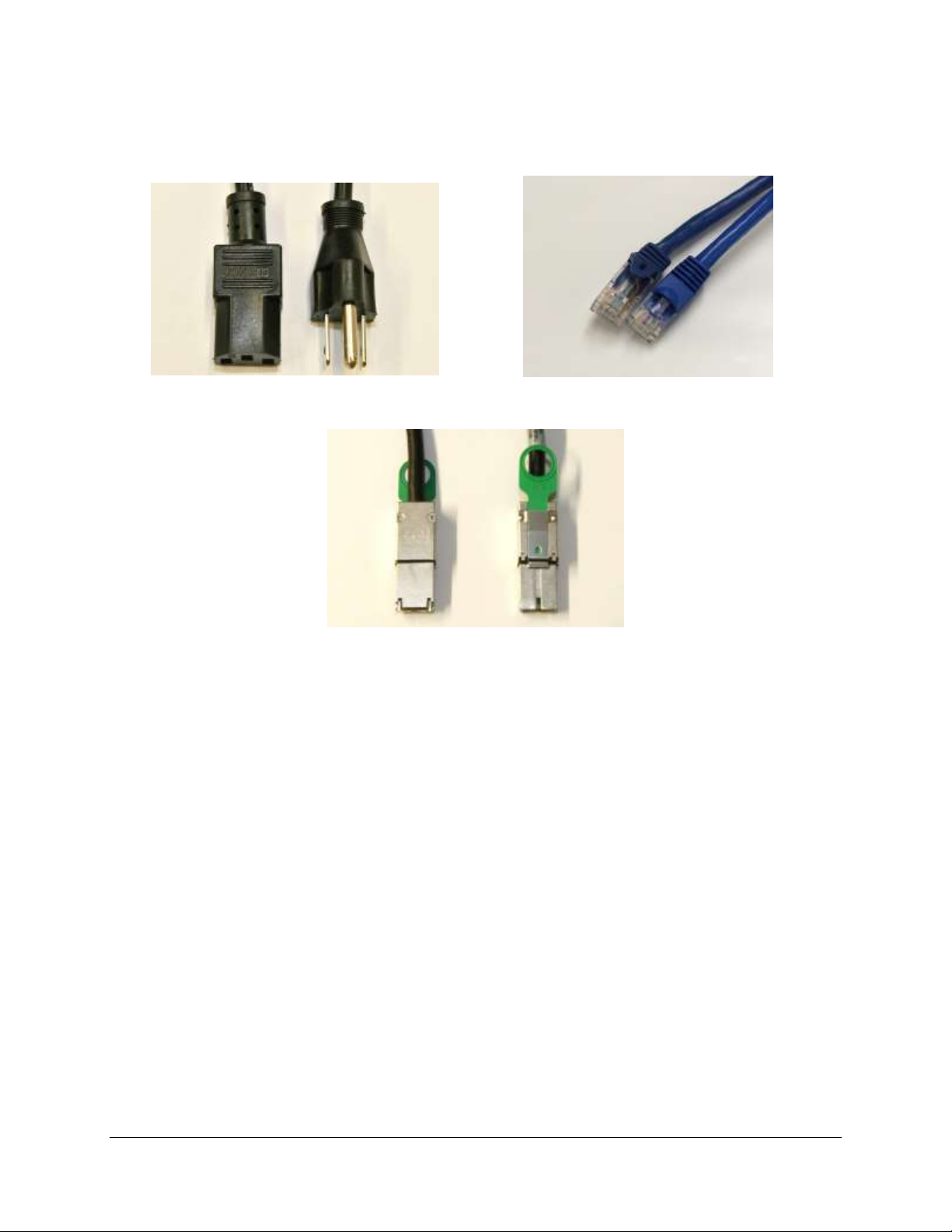
2 Required Components for Installation
Before beginning the installation, verify that the following cables are present:
Figure 1: AC Power Cable Figure 2: Ethernet Cable
Figure 3: PCI-Express Cable
CRT.OM.001514.DRM Page 7 Version1.7
Doremi Labs
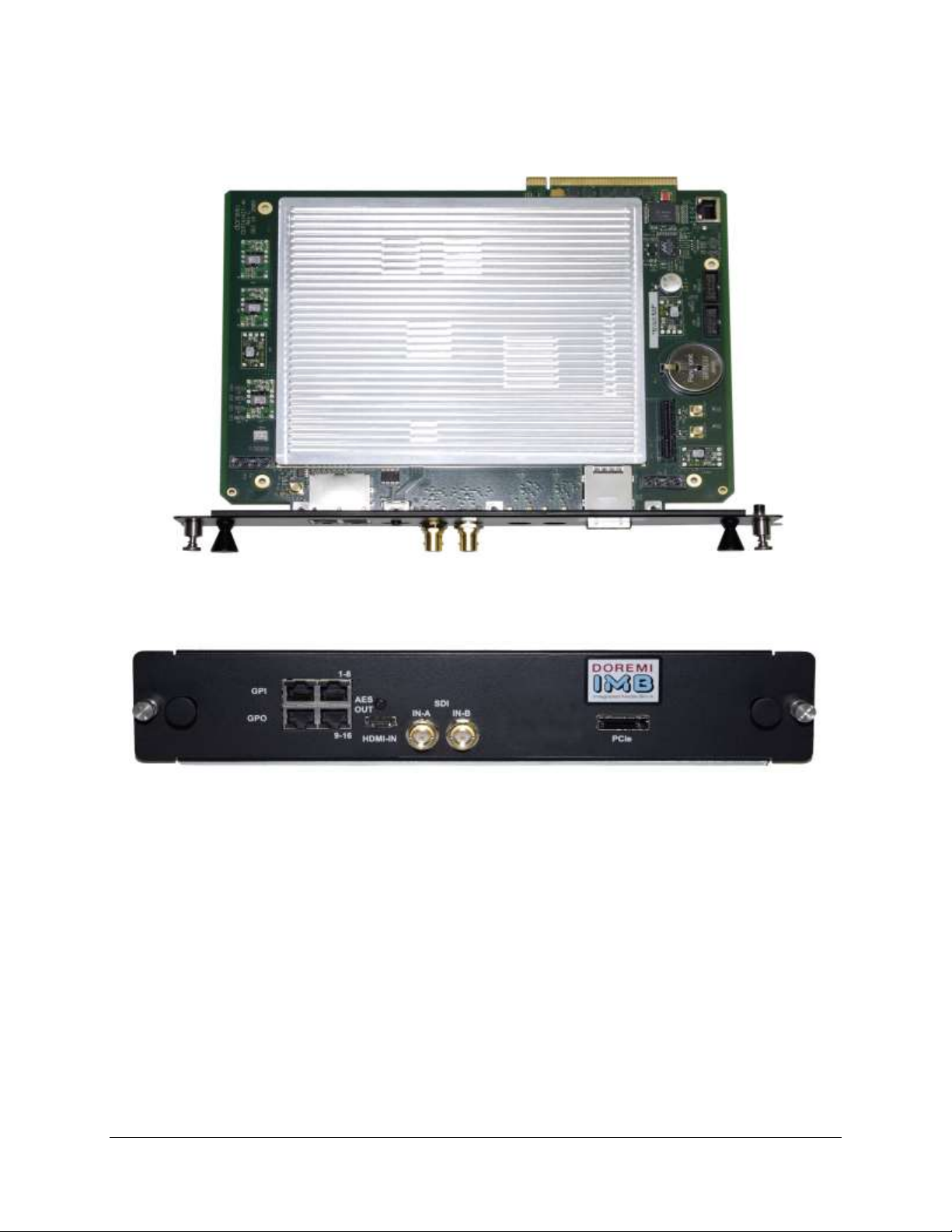
3 IMB Board Installation
Figure 4: IMB
Figure 5: Front Panel
3.1 IMB Technical Specification
3.1.1 HD-SDI Input
Dual HD-SDI input compliant with SMPTE 292M and SMPTE 372M.
HD-SDI input capable of supporting 3 GHz signals per SMPTE 424M. Mapping per
SMPTE 425M is not implemented yet, but it will be available via a software update.
The following are 2D formats that are currently supported on the HDSDI input of the IMB:
CRT.OM.001514.DRM Page 8 Version1.7
Doremi Labs
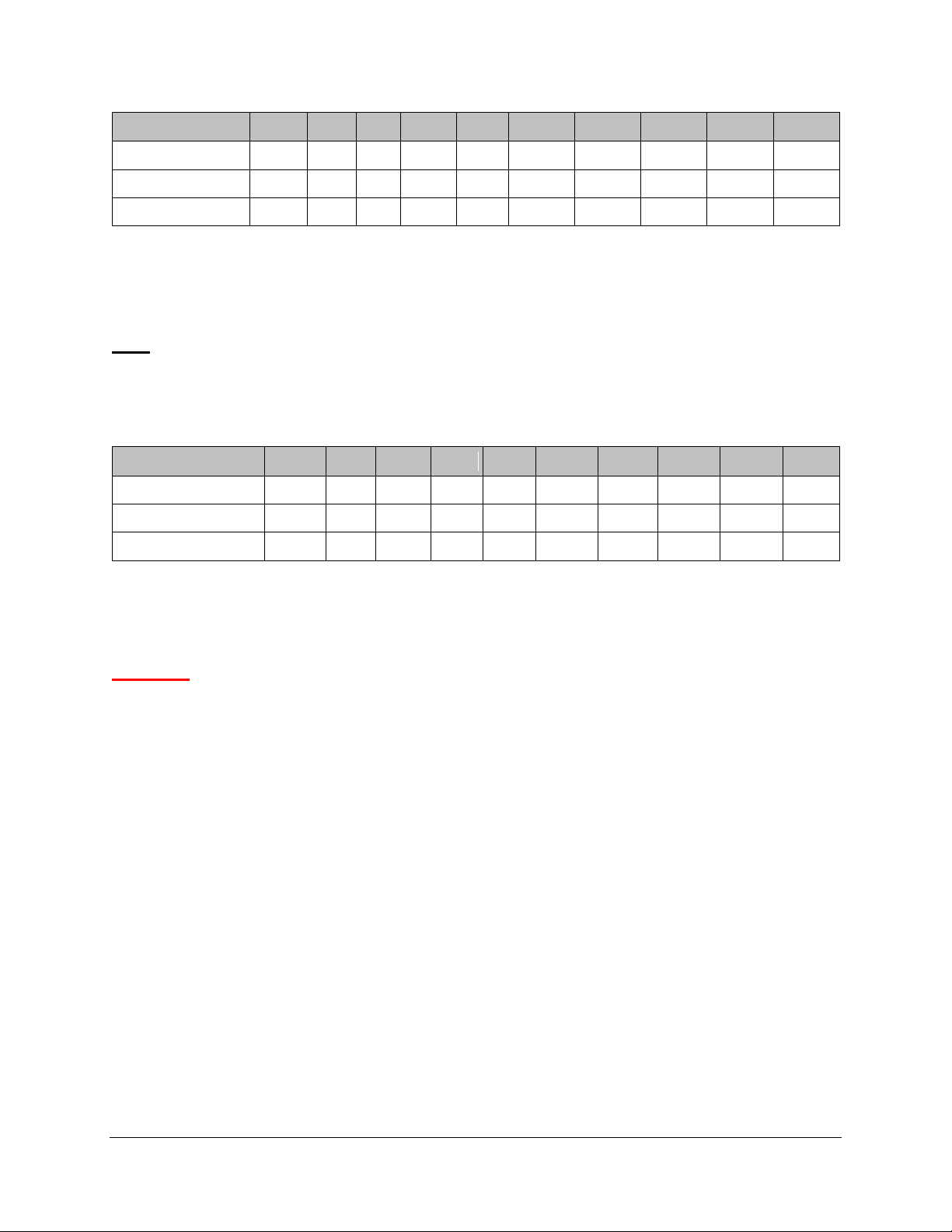
Format\fps
23.98
24
25
29.97
30
47.95
48
50
59.94
60
720p
X X
1080i
X X X X X
1080p
X X X X X
3.1.2 HD-SDI Output
Aspect ratio\fps
23.98
24
25
29.97
30
47.95
48
50
59.94
60
720p
X X X
1080i
X X X X X
1080p
X X X X X X X X X
X
IMB Revision A: HD-SDI output is not available.
IMB Revision E: Dual HD-SDI output compliant with SMPTE 292M and SMPTE 372M.
HD-SDI output capable of supporting 3 GHz signals per SMPTE 424M.
Note: With the current firmware, the HD-SDI Output is not used.
3.1.3 HDMI Input
The IMB incorporates High-Definition Multimedia Interface technology. HDMI®, HDCP
compatible input, supporting deep color video up to 12-bit with the following formats:
3.1.4 IMB Revision E Board Installation
Follow the steps below in order to install the IMB board inside the Series 2 projector:
CAUTION: Make sure to unplug the power cable from the projector before installing the IMB
board.
In order to gain access to the board housing, loosen all 5 screws from the side panel and
unlock the panel with the security key.
CRT.OM.001514.DRM Page 9 Version1.7
Doremi Labs
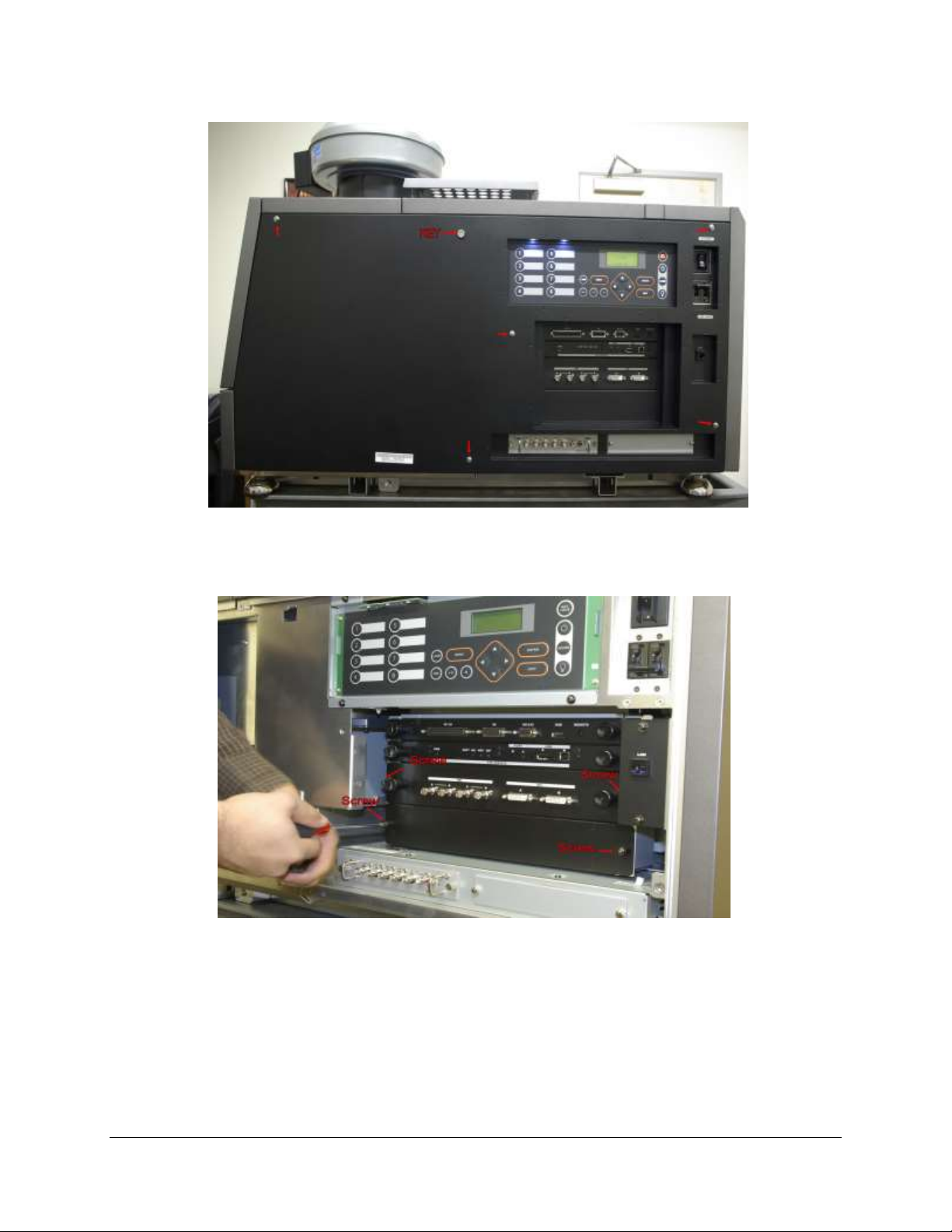
Figure 6: NEC Side Panel
In order to remove the Enigma board the bottom plate must be removed first (Figure 7).
Figure 7: Enigma Removal
Align the IMB board with the guiding rails located on each side of the slot (Figure 8).
CRT.OM.001514.DRM Page 10 Version1.7
Doremi Labs
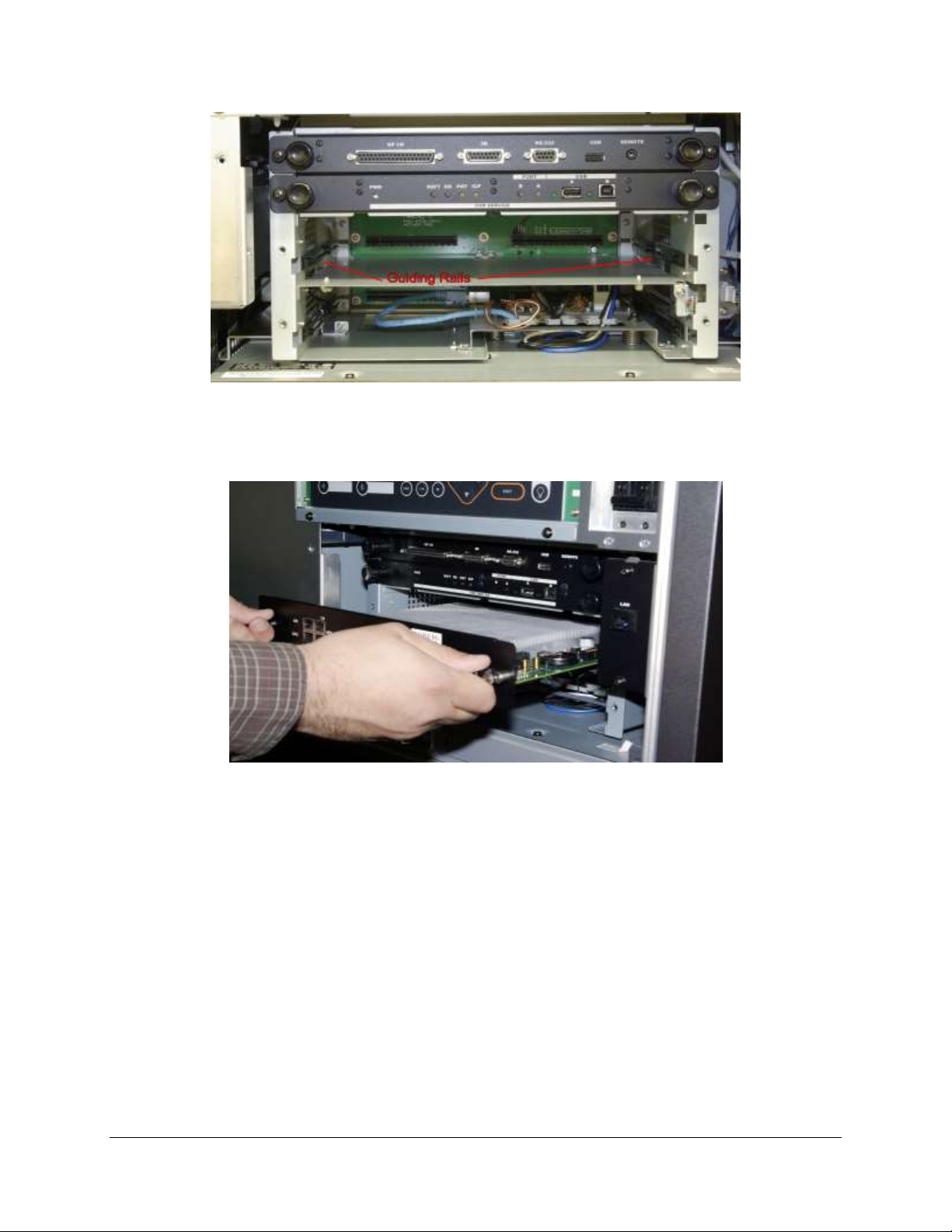
Figure 8: Guiding Rails
Insert the IMB board gently inside the projector.
Figure 9: IMB Installation
Lock the IMB board by using the two locking screws, one on each side of the board
(Figure 10).
Re-insert the bottom plate (Figure 10).
CRT.OM.001514.DRM Page 11 Version1.7
Doremi Labs
 Loading...