

Doosan P425WCU-EX-T2, HP375WCU-EX-T2, XP375WCU-EX-T2 Electronic Service Manual
ELECTRONIC SERVICE MANUAL
COMPRESSOR MODELS
P425WCU-EX-T2 (F66)
HP375WCU-EX-T2 (F67)
XP375WCU-EX-T2 (F65)
P425WCU-EX-T2 (G02)
HP375WCU-EX-T2 (G03)
XP375WCU-EX-T2 (G04)
Doosan Infracore Portable Power
1293 Glenway Drive
Statesville, N.C. 28625
DoosanPortablePower.com
Book: 46673131 (06-2015) Rev A

2

TABLE OF CONTENTS
Electronic Service Manual
TITLE PAGE
GENERAL INFORMATION . . . . . . . . . . . . . . . . . . . . . . . . . . . . . . . . . . . . . . . . . . . . . . . . . . 5
COMPRESSOR OPERATION SEQUENCE. . . . . . . . . . . . . . . . . . . . . . . . . . . . . . . . . . . . . 11
COMPRESSOR DIAGNOSTIC CODE TROUBLESHOOTING . . . . . . . . . . . . . . . . . . . . . . 15
ELECTRICAL CIRCUIT TROUBLESHOOTING . . . . . . . . . . . . . . . . . . . . . . . . . . . . . . . . . 55
E
LECTRICAL COMPONENT LOCATIONS. . . . . . . . . . . . . . . . . . . . . . . . . . . . . . . . . . . . . 67
ELECTRICAL PARTS LIST . . . . . . . . . . . . . . . . . . . . . . . . . . . . . . . . . . . . . . . . . . . . . . . . . 71
SY
STEM SCHEMATICS AND WIRING DIAGRAMS. . . . . . . . . . . . . . . . . . . . . . . . . . . . . . 75
3

TABLE OF CONTENTS
Electronic Service Manual
TITLE PAGE
4

General Information
46673131 Rev. A 5

Electronic Service Manual General Information
Operational Theory
The P425/XP375/HP375WCU-EX-T2 compressor has an electronic system using the Titan
controller to provide discharge air pressure control and package monitoring functions. The
electrical system connects all the necessary switches, sensors, and transducers to the Titan
controller.
Titan Controller
The Titan controller is the heart of the compressor monitoring and control system and
provides data collection, package monitoring, and control functions for compressor
operations. The Titan controller is a microprocessor-based controller with analog and digital
inputs and outputs.
The Titan controller is mounted on the liftbail in the middle of compressor.
The first function of the Titan controller is to scan all inputs at a fixed interval. The analog
values are compared to preset minimum and maximum values and an ALERT or FAULT is
issued when a value is out of range. The various ALERTS and FAULTS are listed in the
Compressor Diagnostic Code Troubleshooting section.
The second function of the Titan controller is compressor discharge pressure control. The
Titan monitors the regulation system air pressure and varies the engine throttle to maintain
the setpoint discharge air pressure. The setpoint pressure is set by adjusting the pressure
regulator.
The third function of the Titan controller is to communicate diagnostic and control information
between the Titan, Micro-Port display, and other optional controllers via the J1939 CAN
network.
Temperature Sensors and Pressure Transducers
The electronics system uses temperature sensors and pressure transducers to monitor the
compressor operation. The temperature sensors used to measure compressor temperatures
are thermistor type devices. The resistance output of the temperature sensor changes with a
corresponding temperature change of the parameter being monitored. The Titan controller
receives the resistance value of the sensor and converts it to a temperature value. The Titan
uses the temperature value to ensure the parameter being monitored is within its operating
limits and relays the value to the Micro-Port display for operator viewing.
The pressure sensors used to measure compressor pressures are transducer type devices.
These sensors have an output signal range of 0.5 VDC to 4.5 VDC, where 0.5 VDC
corresponds to 0 PSI and 4.5 VDC corresponds to the maximum PSI rating for a particular
transducer. Pressure sensors are provided with 5 VDC excitation voltage from the Titan
controller. Also, the sensor return or ground connects to the Titan controller. The output
voltage of the pressure sensor changes with a corresponding pressure change of the
parameter being monitored. The Titan controller receives the voltage of the sensor and
converts it to a pressure value. The Titan uses the pressure value to ensure the parameter
being monitored is within its operating limits and relays the value to the Service Air Pressure
gauge display for operator viewing.
6 46673131 Rev. A

General Information Electronic Service Manual
The Titan controller scans digital inputs such as switch contacts. Inputs are 24 VDC, 12 VDC,
or 0 VDC. Digital inputs with 24 VDC or 12 VDC represent a closed switch contact. Digital
inputs with 0 VDC represent an open switch contact.
The Titan controller provides 12 VDC digital outputs to control solenoids, relays, and other
devices. Outputs are 12 VDC ON and 0 VDC OFF and are current limited and short circuit
protected.
The Titan controller has 12 VDC digital (ON/OFF) type outputs.
Micro-Port Display
The Micro-Port displays compressor and engine operational information to the operator. The
Micro-Port display can be navigated by using the UP, DOWN, and ENTER buttons on the
Keypad.
The Micro-Port display is connected to the J1939 CAN network for communication with other
devices on the network.
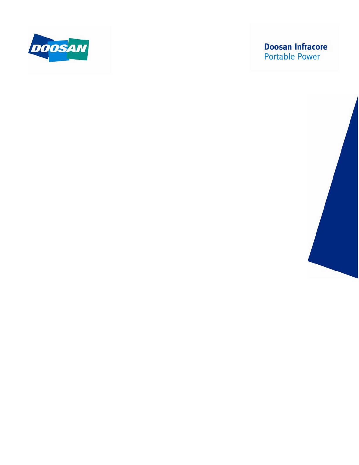
J1939 CAN Network
The J1939 CAN network is a twisted pair of wires located in the compressor and engine
harnesses. These wires are the network link between all electronic control modules. The
wires are color coded yellow and dark green. The yellow wire is referred to as CAN High (+)
and the dark green wire is referred to as CAN Low (-). Figure 1-2 shows the connection layout
of the CAN network.
Located on each end of the J1939 CAN network are termination resistors (terminator). The
terminators prevent reflections on the transmission line and must be in place for the network
to function properly.
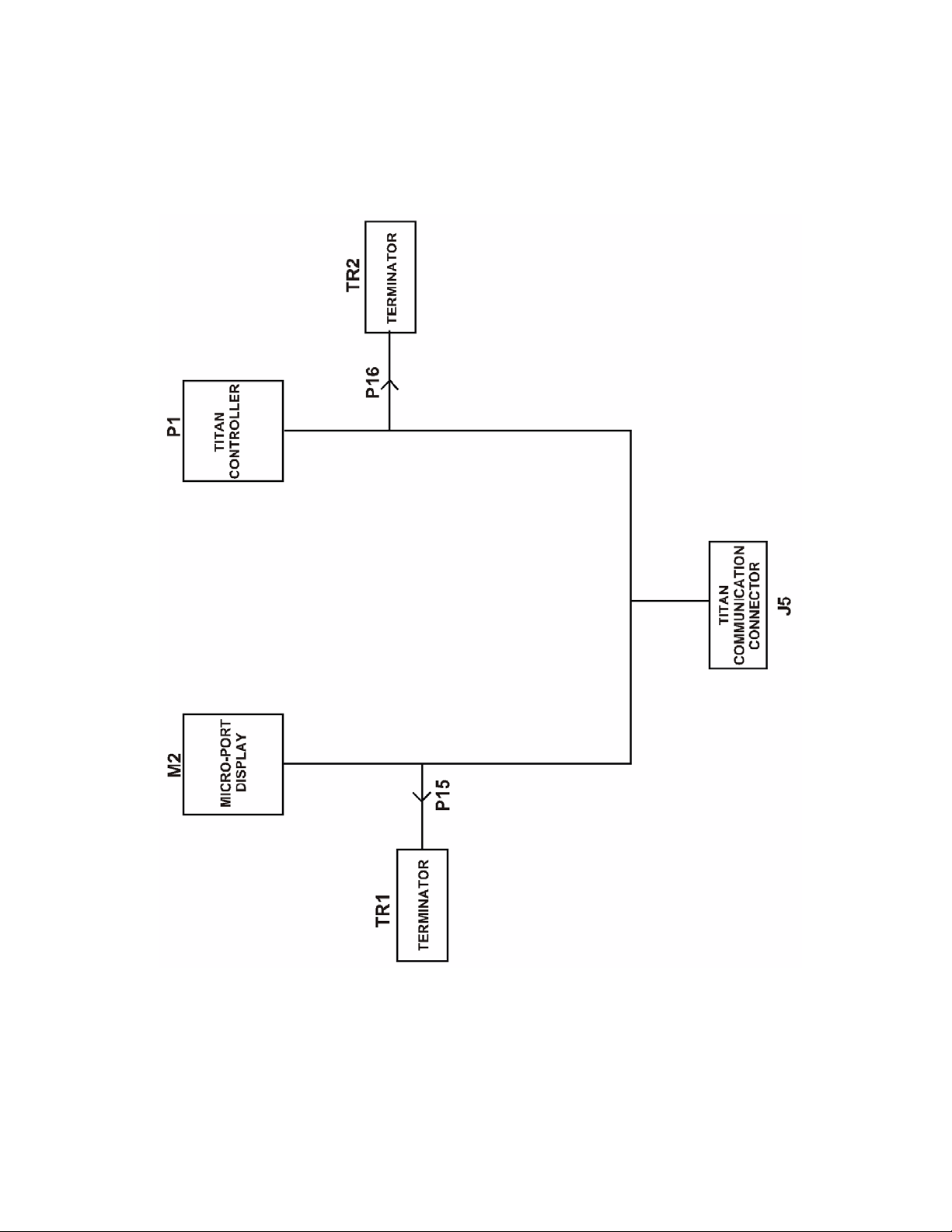
Electrical System
The electrical system consists of the wiring harnesses and associated electrical devices such
as relays, switches, sensors, and solenoids. There are three wiring harnesses on this
compressor:
• Compressor and Engine Harness
• Engine Intake Air Heater Harness
Figure 1-3 shows the connection layout of the harness system.
The electrical circuits are protected by fuses. A fuse should only be replaced with one of the
same rating. Installing a larger rated fuse could lead to wiring harness damage.
46673131 Rev. A 7
Electronic Service Manual General Information
Figure 1-2 : J1939 CAN BUS CONNECTION LAYOUT
8 46673131 Rev. A
General Information Electronic Service Manual
Figure 1-3 : HARNESS SYSTEM CONNECTION LAYOUT
46673131 Rev. A 9

Electronic Service Manual General Information
10 46673131 Rev. A

Compressor Operation Sequence
46673131 Rev. A 11

Electronic Service Manual Compressor Operation Sequence
Power On
When the Keyswitch is in the ON position:
1. Key ON/OFF signal (12 VDC) supplied to Titan controller.
2. Titan controller energizes Switched Power Relay (FB1-K3).
3. Micro-Port display and gauges will initialize.
4. Gauge backlights power ON.
5. Regulation heaters (if equipped) are energized ON if ambient temperature is
below 45°F. Engine intake heaters are energized if ambient temperature is
below 60°F.
Start
When the Keyswitch is in the START position:
1. Unloader Solenoid Valve (L2) is closed (de-energized).
2. Engine Starter is energized.
When the engine speed reaches 1000 RPM (engine start declared):
1. Engine starter is de-energized.
2. Engine speed is set to 1500 RPM.
When the engine speed is greater than 1100 RPM:
1. Unloader Solenoid Valve (L2) is opened (energized).
Loading
When the Start/Run Valve is pressed:
1. Engine speed is set to 2200 RPM.
12 46673131 Rev. A

Electronic Service Manual Compressor Operation Sequence
Shutdown
Close the service valves(s). Allow the compressor to run at idle speed for 3 to 5 minutes to
allow cool down. Do not use E-Stop (if equipped) to stop machine unless it is an emergency.
When the Keyswitch is moved to the OFF position:
1. Keyswitch signal (12VDC) from Titan is de-engerized.
2. The engine will shut down.
3. The Titan controller and Switched Power Relay (FB1-K3) de-energize.
4. Micro-Port display, gauges, and Compressor Control System will turn OFF.
46673131 Rev. A 13

Electronic Service Manual Compressor Operation Sequence
14 46673131 Rev. A

Compressor Diagnostic Code
Troubleshooting
46673131 Rev. A 15

Electronic Service Manual Compressor Diagnostic Code Troubleshooting
General
A thorough analysis of the problem is the key to successful troubleshooting. The
more information known about a problem, the faster and easier the problem can be
solved.
Troubleshooting charts are included to act as a guide to the troubleshooting
process.
The charts are organized so the easiest and most logical things are performed first.
It is not possible to include all the solutions to problems that can occur or list all
possible problems.
The charts are designed to stimulate a thinking process that will lead to the solution
of a problem.
Basic Troubleshooting Steps
• Collect all facts concerning the problem.
• Analyze the problem thoroughly.
• Relate the symptoms to the basic electrical/electronic systems and
components.
• Consider any recent repairs that could relate to the problem.
16 46673131 Rev. A

Compressor Diagnostic Code Troubleshooting Electronic Service Manual
General Measuring Guidelines
Since the electrical system uses sealed connectors and splices, access of test
points can be difficult. It is recommended a test probe kit be used to access the
signals to prevent damage to wires and connectors. Back-probing connectors and
insulation piercing test probes can cause damage that can cause future failures.
Measuring Voltage
A digital voltmeter is recommended to make measurements. Voltage
measurements are made by connecting the Red (+) lead to the desired signal and
the Black (-) lead to the common. The test lead connections must be secure or
incorrect readings will result. Do NOT use chassis ground or other metal
connection. Circuit common will be any of the brown wires or battery Negative.
IMPORTANT INFORMATION
DO NOT USE MACHINE FRAME, SHEET METAL, PIPING, OR OTHER METAL
COMPONENTS AS COMMON OR GROUND WHEN MAKING VOLTAGE OR
FREQUENCY MEASUREMENTS.
Measuring Resistance
Extra care must be taken when making resistance measurements. Test probe
connections are crucial to correct readings. Ensure the test probe makes a solid
connection with the wire(s) or connector pin(s) under test. The test probe kit may
help with these types of measurements. Electrical system must be powered OFF
while making resistance measurements.
Measuring Frequency
Frequency is measured in the same manner as voltage, but the meter is set for HZ
or frequency. Good connections are important or false readings will occur.
Measuring Duty Cycle
To measure duty cycle, set up the meter as if measuring frequency or voltage.
Select the % or duty cycle function and take the measurements.
46673131 Rev. A 17
Electronic Service Manual Compressor Diagnostic Code Troubleshooting
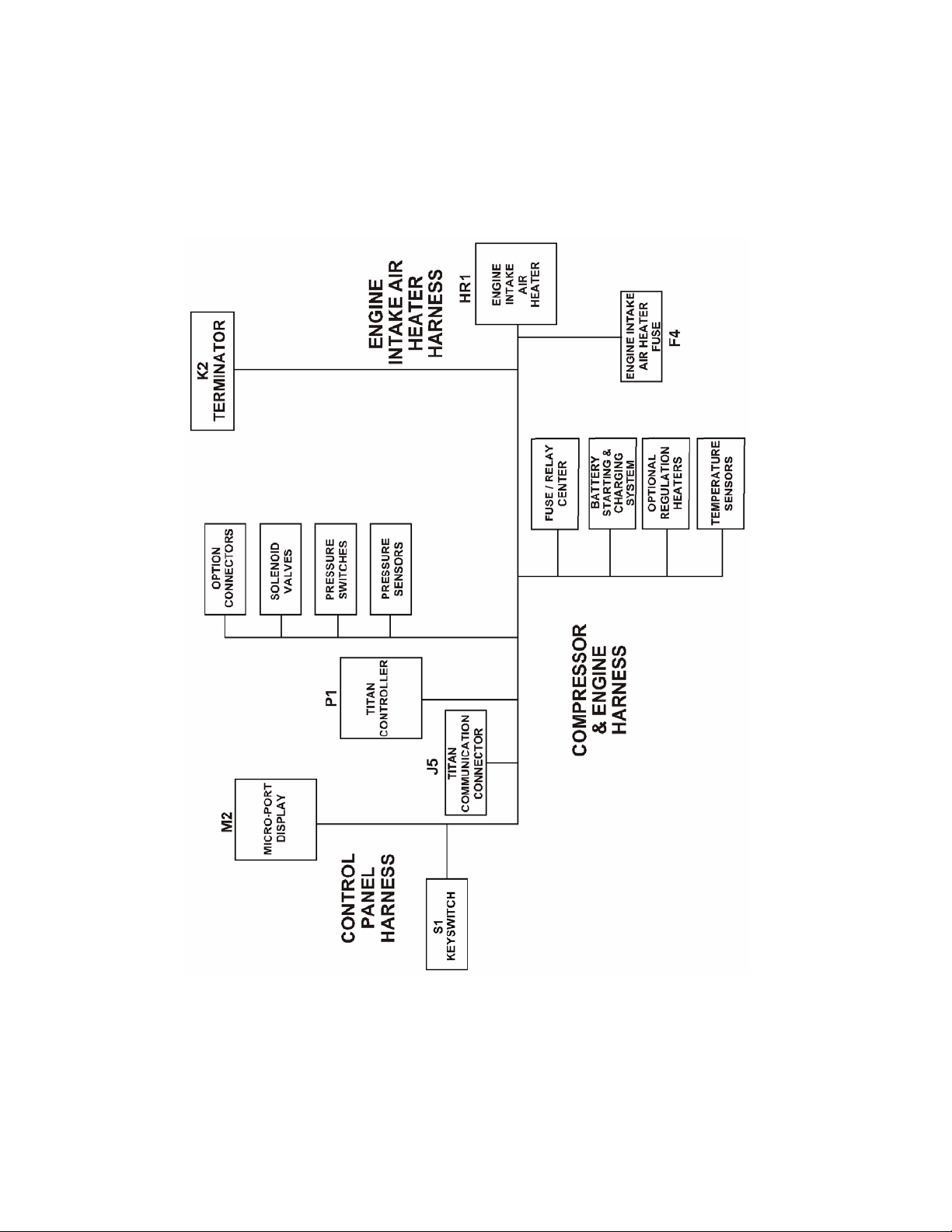
Troubleshooting Flow Chart
18 46673131 Rev. A

Compressor Diagnostic Code Troubleshooting Electronic Service Manual
Compressor Diagnostic Codes
LCD Display Display Name Description
CPR CODE 1
LOW ENGINE
SPEED
CPR CODE 2
HIGH ENGINE
SPEED
CPR CODE 3
WAIT 30 SEC
RETRY START
CPR CODE 4
OUT OF FUEL
CPR CODE 12
FUEL LEVEL
LOW
CPR CODE 16
HIGH ENGINE
TEMP
Low Engine Speed Engine speed less than 1100
RPM for 30 seconds.
High Engine Speed Engine speed greater than 2350
RPM for 30 seconds.
Engine Crank Timeout Engine crank attempt longer
than 15 seconds above 50°F or
longer than 30 seconds below
32°F.
Out of Fuel Fuel level in tank below usable
limit.
Low Fuel Level Fuel level in tank approaching
empty.
High Engine
Temperature
Engine coolant temperature
greater than 212°F (Engine
derate begins).
Code
Type
FAULT
FAULT
FAULT
FAULT
ALERT
ALERT
CPR CODE 17
HIGH ENGINE
TEMP
CPR CODE 18
LOW OIL
PRESSURE
CPR CODE 29
ENGINE
SHUTDOWN?
CPR CODE 30
HIGH AIREND
TEMP
CPR CODE 32
AIREND DISC
TEMP SENSOR
CPR CODE 33
SEP TANK
PRES SENSOR
CPR CODE 34
HIGH PRES AT
START
High Engine
Temperature
(Shutdown)
Low Oil Pressure Low engine oil pressure. Open
Engine Shutdown
Unknown
High Airend Discharge
Temperature
Airend Discharge
Temperature Sensor
Separator Tank
Pressure Sensor
High Separator Tank
Pressure At Start
Engine coolant temperature
greater than 215°F in 3 seconds
(Engine Shutdown).
for 3 seconds.
Engine stopped without an
engine diagnostic code.
Airend discharge temperature
greater than or equal to 251°F. 3
seconds.
Airend Discharge Temperature
Sensor reading out of range.
Separator Tank Pressure
Sensor reading out of range.
Separator tank pressure greater
than 20 psi at crank attempt.
FAULT
FAULT
FAULT
FAULT
FAULT
FAULT
ALERT
46673131 Rev. A 19

Electronic Service Manual Compressor Diagnostic Code Troubleshooting
LCD Display Display Name Description
CPR CODE 36
SAFETY V ALVE
OPEN
CPR CODE 38
AIR FILTERS
RESTRICTED
CPR CODE 39
LOW SYSTEM
VOLTAGE
CPR CODE 42
FUEL LEVEL
SENSOR
CPR CODE 50
HIGH SEP
TANK TEMP
CPR CODE 51
COMPRESSOR
ID INVALID
Safety Valve Open Safety relief valve on separator
Intake Air Filters
Restricted
Low System Voltage/
Alternator Not Charging
Fuel Level Sensor Fuel Level Sensor reading out of
High Separator Tank
Temperature
Compressor ID Invalid The Titan controller and Engine
tank opened.
Intake filters restricting air flow. ALERT
Electrical system voltage below
13.3 VDC for 30 seconds or
more.
range.
Separator tank temperature
greater than or equal to 251°F.
for 3 seconds.
T achometer with MidPort display
do not have a valid compressor
ID.
Code
Type
FAULT
ALERT
ALERT
FAULT
FAULT
CPR CODE 52
IQ FILTERS
RESTRICTED
CPR CODE 53
SEP TANK
TEMP SENSOR
CPR CODE 58
AMBIENT
TEMP SENSOR
CPR CODE 73
AUTOSTART
CTRL COMMS
CPR CODE 76
CPR CTRL
COMMS
IQ Filters Restricted IQ filters restricted past usable
level. 3 seconds.
Separator Tank
Temperature Sensor
Ambient Temperature
Sensor
AutoStart Controller
Communication
Compressor Controller
Communication
Separator Tank Temperature
Sensor reading out of range.
Ambient Temperature Sensor
reading out of range.
Communication between Titan
controller and AutoStart
controller not functional.
Communication between Titan
controller and Engine
T achometer with MidPort display
not functional.
FAULT
FAULT
ALERT
ALERT
ALERT
20 46673131 Rev. A

Compressor Diagnostic Code Troubleshooting Electronic Service Manual
COMPRESSOR CODE 1
Low Engine Speed
Explanation
The Titan controller has received an engine speed value less than 1100 RPM for
30 seconds from the engine.
Effect
Code 1 is a FAULT condition and will shut down the compressor. CPR CODE 1
LOW ENGINE SPEED will be shown on the Micro-Port display.
Troubleshooting Steps
Action Result
Step 1:
Check Micro-Port display for active
engine diagnostic codes.
Step 2:
Start and run the compressor at idle.
Check Micro-Port display to verify the
engine target (RPM). If the engine
coolant temperature is below 100°F,
the engine target (RPM) will be 1500
RPM. If the engine coolant
temperature is 100°F or above, the
engine target (RPM) will be 1400
RPM.
Step 3:
Check the engine fuel system for
restrictions.
If active engine diagnostic codes are
present, resolve the issues.
If the engine target (RPM) is 1500 for
cold idle or 1400 for hot idle, the
electronic system is commanding the
engine to run at the correct speed.
Proceed to Step 3.
If the fuel filters are dirty or have not
been changed during regular service,
replace fuel filters.
If dirty fuel has been used, add clean
fuel and replace fuel filters.
If air has gotten into the fuel system,
bleed the fuel system.
If fuel hoses are damaged, replace
fuel hoses.
46673131 Rev. A 21

Electronic Service Manual Compressor Diagnostic Code Troubleshooting
Action Result
Step 4:
If Steps 1 thru 3 checkout OK, refer to
the engine manufacturer service
dealer.
22 46673131 Rev. A

Compressor Diagnostic Code Troubleshooting Electronic Service Manual
COMPRESSOR CODE 2
High Engine Speed
Explanation:
The Titan controller has measured an engine speed value greater than 2350 RPM
for 30 seconds.
Effect:
Code 2 is a FAULT condition and will shut down the compressor. CPR CODE 2
HIGH ENGINE SPEED will be shown on the Micro-Port display.
Troubleshooting Steps
Action Result
Step 1:
Check Micro-Port display for active
engine diagnostic codes.
Step 2:
Start and run the compressor at idle.
Press the Start/Run Valve after
warmup of engine for 3 minutes or
reaching engine coolant temperature
of 150°F. Check Micro-Port display to
verify the engine target (RPM) is 2200.
Step 3:
If Steps 1 and 2 checkout OK, refer to
the engine manufacturer service
dealer.
If active engine diagnostic codes are
present, resolve the issues.
If the engine target (RPM) is 2200, the
electronic system is commanding the
engine to run at the correct speed.
Proceed to Step 3.
46673131 Rev. A 23

Electronic Service Manual Compressor Diagnostic Code Troubleshooting
COMPRESSOR CODE 3
Engine Crank Timeout
Explanation:
The electronic system has attempted to start the compressor longer than 15
seconds above 50°F ambient or longer than 30 seconds below 32°F ambient.
Effect:
Code 3 is a FAULT condition and will prevent further cranking. CPR CODE 3 WAIT
30 SEC RETRY START will be shown on the Micro-Port display. Operator must
wait 30 seconds before electronic system will allow another start attempt.
Troubleshooting Steps
Action Result
Step 1:
Wait 30 seconds before attempting to
start compressor.
Step 2:
Check the engine fuel system for
restrictions.
Step 3:
If ambient temperature is below 10°F,
verify Cold Weather Kit is functioning
(if equipped).
After 30 seconds, the electronic
system will allow another 15 or 30
second start attempt depending on
ambient temperature.
If the fuel filters are dirty or have not
been changed during regular service,
replace fuel filters.
If dirty fuel has been used, add clean
fuel and replace fuel filters.
If air has gotten into the fuel system,
bleed the fuel system.
If fuel hoses are damaged, replace
fuel hoses.
If Cold Weather Kit is not functioning,
repair as needed.
If Cold Weather Kit is not installed, it is
required to start compressor in
ambient temperatures below 10°F.
24 46673131 Rev. A

Compressor Diagnostic Code Troubleshooting Electronic Service Manual
COMPRESSOR CODE 4
Out Of Fuel
Explanation:
The Titan controller has detected a condition from U1 Fuel Level Sensor indicating
the fuel level in the tank is below a usable limit.
Effect:
Code 4 is a FAULT condition and will shut down the compressor. CPR CODE 4
OUT OF FUEL will be displayed on the Micro-Port display.
Troubleshooting Steps
Action Result
Step 1:
Check fuel level in tank.
Step 2:
Check all harness connections
between Titan and U1 Fuel Level
Sensor.
Step 3:
Remove fuel level sensor from fuel
tank. With the fuel level sensor
connected to the harness, turn the
sensor upside down so float will go to
the top. Turn the Keyswitch to the ON
position to energize the compressor
electronic system. Verify the fuel level
on the gauge is FULL and CPR CODE
4 clears from the Micro-Port display.
Step 4:
With the fuel level sensor still removed
from the tank and the compressor
electronic system energized, tilt the
fuel sensor so the float will move
down. Verify the fuel level gauge is
moving down the scale.
If the fuel level is low, add fuel.
If harness connections are loose or
damaged, repair harness as needed.
If CPR CODE 4 clears and the fuel
level gauge shows FULL, the fuel level
sensor is operating properly.
If CPR CODE 4 does not clear and the
fuel level gauge shows EMPTY,
replace U1 Fuel Level Sensor.
If the float in the fuel level sensor
appears to be sticking while moving,
replace U1 Fuel Level Sensor.
46673131 Rev. A 25

Electronic Service Manual Compressor Diagnostic Code Troubleshooting
Action Result
Step 5:
If Step s 1 thru 4 checkout OK, replace
Titan controller.
26 46673131 Rev. A

Compressor Diagnostic Code Troubleshooting Electronic Service Manual
COMPRESSOR CODE 12
Low Fuel Level
Explanation:
The Titan controller has detected a condition from U1 Fuel Level Sensor indicating
the fuel level in the tank is approaching empty.
Effect:
Code 12 is an ALERT condition and will not shut down the compressor. CPR
CODE 12 FUEL LEVEL LOW will be shown on the Micro-Port display.
Troubleshooting Steps
Action Result
Step 1:
Check fuel level in tank.
Step 2:
Check all harness connections
between Titan and U1 Fuel Level
Sensor.
Step 3:
Remove fuel level sensor from fuel
tank. With the fuel level sensor
connected to the harness, turn the
sensor upside down so float will go to
the top. Turn Keyswitch to the ON
position to energize the compressor
electronic system.Verify the fuel level
on the gauge is FULL and CPR CODE
12 clears from the Micro-Port display.
Step 4:
With the fuel level sensor still removed
from the tank and the compressor
electronic system energized, tilt the
fuel sensor so the float will move
down. Verify the fuel level gauge is
moving down the scale.
If the fuel level is low, add fuel.
If harness connections are loose or
damaged, repair harness as needed.
If CPR CODE 12 clears and the fuel
level gauge shows FULL, the fuel level
sensor is operating properly.
If CPR CODE 12 does not clear and
the fuel level gauge shows EMPTY,
replace U1 Fuel Level Sensor.
If the float in the fuel level sensor
appears to be sticking while moving,
replace U1 Fuel Level Sensor.
46673131 Rev. A 27
 Loading...