

Doosan DE12T, P126TI-1, P126TI, P126TI-II Operation & Maintenance Manual

FOREWORD
This manual is designed to serve as an instruction for the Operation & Maintenance of generating-set
engines of Doosan POLUS series: P126TI- /P126TI /P126TI-1/DE12T. The POLUS means ‘Power
Plus’ that is represented more powerful Doosan generating-set engines and it is marked on engine
name as an initial P. On the other hand, intial D stands for standard engine prior to POLUS version.
The first half is for operation and the latter half is for maintenance like disassembling, inspecting and
re-assembling etc in order to help an understanding for the maintenance procedure more easily.
To keep the best performance and the durability of engine for a long time, CORRECT OPERATION
and PROPER MAINTENANCE are essential.
In this manual, the following symbols are used to indicate the type of service operations to be
performed.
Removal Adjustment
Installation Cleaning
Disassembly Pay close attention-Important
Reassembly Tighten to specified torque
Align the marks Use special tools of manufacturer
Directional Indication Lubricate oil
Inspection Lubricate grease
Measurement
If you have any question or recommendation in connection with this manual, please do not hesitate
to contact our head office, dealers or authorized service shops near by your location for any services.
Also some figures in this manual may be different from the actual appearance of the engine because
of explaining them with the representative figure among these models
For the last, the contents of this instruction manual may be changed without prior notice for some
quality improvement. Thank you.
Nov. 2003
DOOSAN Infracore Co., Ltd.

CONTENTS
<Operation>
1. Safety Regulations ................................................................................................................... 1
1.1. General Notes 1.4.
Regulations Designed to Prevent Pollution
1.2.
Regulations Designed to Prevent Accidents
1.5.
Notes on Safety in Handling Used Engine Oi
l
1.3.
Regulations Designed to Prevent
Damage to Engine and Premature Wear
2. General Information .................................................................................................................. 5
2.1. Engine Assembly 2.2. Engine Specification
3. Technical Information ............................................................................................................. 10
3.1. Engine Model and Serial Number 3.7. Fuel System
3.2. Engine Type 3.8. Cooling System
3.3. Engine Timing 3.9. V-belt Tension Check and Adjust
3.4. Valves 3.10. Turbocharger
3.5. Lubrication System 3.11. Electrical Equipment
3.6. Air Cleaner
4. Commissioning and Operation ............................................................................................. 23
4.1. Preparation 4.4. Operation in Winter Time
4.2. Breaking-in 4.5. Tuning the Engine
4.3. Inspection after Starting
5. Maintenance and Care ............................................................................................................ 27
5.1. Periodical Inspection and Maintenance 5.5. Fuel System
5.2. Lubrication System 5.6. Injection Nozzle Maintenance
5.3. Cooling System 5.7. Turbocharger
5.4. Air Intake System
6. Checking and Setting ............................................................................................................. 41
6.1. Adjustment of Valve Clearance 6.3. Cylinder Compression Pressure
6.2. Adjustment of Injection Timing 6.4. V-belts
7. Operation Tip ........................................................................................................................... 47
7.1. Periodic Inspection Cycle 7.3. Causes and Remedies
7.2. Trouble Shooting

<Maintenance>
8. General Information ................................................................................................................ 58
8.1. General Repair Instructions 8.2. Engine Characteristics
9. Disassembly and Reassembly of Major Components ........................................................ 60
9.1. Disassembly 9.3. Reassembly
9.2. Inspection 9.4. Breaking-in
10. Maintenance of Major Components .................................................................................. 11 3
10.1. Cooling System 10.3. Fuel Injection Pump
10.2. Lubricating System 10.4. Turbocharger
11. Special Tool List .................................................................................................................. 163
•
Appendix
•
Part & After service center
•
Applications for Doosan Engine

1. Safety Regulations
1.1. General Notes
Handling diesel engines and the necessary resources is no problem when the personnel com-
missioned with operation and maintenance are trained accordingly and use their common
sense.
This summary is a compilation of the most important regulations. These are broken down into
main sections which contain the information necessary for preventing injury to persons, damage
to property and pollution. In addition to these regulations those dictated by the type of engine
and its site are to be observed also.
Important :
If, despite all precautions, an accident occurs, in particular through contact with caustic
acids, fuel penetrating the skin, scalding from oil, antifreeze being splashed in the eyes etc.,
consult a doctor immediately.
1.2. Regulations Designed to Prevent Accidents
1.2.1. During commissioning, starting and operation
Before putting the engine into operation for the first time, read the operating instructions care-
fully and familiarize yourself with the ÒcriticalÓ points, If you are unsure, ask your DAEWOO rep-
resentative.
¥
For reasons of safety we recommend you attach a notice to the door of the engine room pro-
hibiting the access of unauthorized persons and that you draw the attention of the operating
personal to the fact that they are responsible for the safety of persons who enter the engine
room.
¥
The engine must be started and operated only by authorized personnel. Ensure that the
engine cannot be started by unauthorized persons.
¥
When the engine is running, do not get too close to the rotating parts. Wear close-fitting cloth-
ing.
¥
Do not touch the engine with bare hands when it is warm from operation risk of burns.
¥
Exhaust gases are toxic. Comply with the installation instructions for the installation of DAE-
WOO generator diesel engines which are to be operated in enclosed spaces. Ensure that
there is adequate ventilation and air extraction.
¥
Keep vicinity of engine, ladders and stairways free of oil and grease.
Accidents caused by slipping can have serious consequences.
- 1 -

1.2.2. During maintenance and care
¥
Always carry out maintenance work when the engine is switched off. If the engine has to be
maintained while it is running, e.g. changing the elements of change-over filters, remember
that there is a risk of scalding. Do not get too close to rotating parts.
¥
Change the oil when the engine is warm from operation.
Caution :
There is a risk of burns and scalding. Do not touch oil drain valve or oil filters with bare
hands.
¥
Take into account the amount of oil in the sump. Use a vessel of sufficient size to ensure that
the oil will not overflow.
¥
Open the coolant circuit only when the engine has cooled down. If opening while the engine
is still warm is unavoidable, comply with the instructions In the chapter entitled ÒCoolingÓ.
¥
Neither tighten up nor open pipes and hoses (lube oil circuit, coolant circuit and any additional
hydraulic oil circuit) during the operation. The fluid which flow out can cause injury.
¥
Fuel is inflammable. Do not smoke or use naked lights in its vicinity. The tank must be filled
only when the engine is switched off.
¥
Keep service products (anti-freeze) only in containers which can not be confused with drinks
containers.
¥
Comply with the manufacturerÕs instructions when handling batteries.
Caution :
Accumulator acid is toxic and caustic. Battery gases are explosive.
1.2.3. When carrying out checking, setting and repair work
¥
Checking, setting and repair work must be carried out by authorized personnel only.
¥
Use only tools which are in satisfactory condition. Slip caused by the worn open-end wrench
could lead to Injury.
¥
When the engine is hanging on a crane, no-one must be allowed to stand or pass under it.
Keep lifting gear in good condition.
¥
When checking injectors, do not put your hands under the jet of fuel.
Do not inhale at atomized fuel.
¥
When working on the electrical system disconnect the battery earth cable first. Connect it up
again last in prevent short circuits.
1.3. Regulations Designed to Prevent Damage to Engine and Premature Wear
1) Never demand more of the engine than it was designed to yield for its intended purpose.
Detailed information on this can be found in the sales literature. The injection pump must not be
adjusted without prior written permission of DAEWOO.
- 2 -

2) If faults occur, find the cause immediately and have it eliminate in order to prevent more serious
of damage.
3) Use only genuine DAEWOO spare parts. DAEWOO will accept no responsibility for damage
resulting from the installation of other parts which are supposedly Òjust as goodÓ.
4) In addition to the above, note the following points.
¥
Never let the engine run when dry, i.e. without lube oil or coolant. Use only DAEWOO-
approved service products (engine oil, anti-freeze and anticorrosion agent).
¥
Pay attention to cleanliness, The Diesel fuel must be free of water. See ÒMaintenance and
careÓ.
¥
Have the engine maintained at the specified intervals.
¥
Do not switch off the engine immediately when it is warm, but let it run without load for about
5 minutes so that temperature equalization can take place.
¥
Never put cold coolant into an overheated engine. See ÒMaintenance and careÓ.
¥
Do not add so much engine oil that the oil level rises above the max. marking on the dipstick.
Do not exceed the maximum permissible tilt of the engine. Serious damage to the engine may
result if these instructions are not adhered to.
¥
Always ensure that the testing and monitoring equipment (for battery charge, oil pressure, and
coolant temperature) function satisfactorily.
¥
Comply with instructions for operation of the alternator. See ÒCommissioning and operationÓ.
¥
Do not let the water pump run dry. If there is a risk of frost, drain the water when the engine
switched off.
1.4. Regulations Designed to Prevent Pollution
1.4.1. Engine oil, filter element, fuel filter
¥
Take old oil only to an oil collection point. Take strict precautions to ensure that oil does not
get into the drains or into the ground.
¥
The drinking water supply may be contaminated.
¥
Oil and fuel filter elements are classed as dangerous waste and must be treated as such.
1.4.2. Coolant
¥
Treat undiluted anti-corrosion agent and / or antifreeze as dangerous waste.
¥
When disposing of spent coolant comply with the regulations of the relevant local authorities.
1.5. Notes on Safety in Handling Used Engine Oil
Prolonged or repeated contact between the skin and any kind of engine oil decreases the skin.
Drying, irritation or inflammation of the skin may therefore occur. Used engine oil also contains
dangerous substances which have caused skin cancer in animal experiments. If the basic rules
of hygiene and health and safety at work are observed, health risks are not to the expected as
a result of handling used engine oil.
- 3 -

Health precautions
¥
Avoid prolonged or repeated skin contact with used engine oil.
¥
Protect your skin by means of suitable agents (creams etc.) or wear protective gloves.
¥
Clean skin which has been in contact with engine oil.
- Wash thoroughly with soap and water, A nailbrush is an effective aid.
- Certain products make it easier to clean your hands.
- Do not use petrol, Diesel fuel, gas oil, thinners or solvents as washing agents.
¥
After washing apply a fatty skin cream to the skin.
¥
Change oil-soaked clothing and shoes.
¥
Do not put oily rags into your pockets.
Ensure that used engine oil is disposed of properly.
- Engine oil can endanger the water supply -
For this reason do not let engine oil get into the ground, waterways, the drains or the sewers.
Violations are punishable. Collect and dispose of used engine oil carefully.
For information on collection points please contact the seller, the supplier or the local authori-
ties.
- 4 -
2. General Information
2.1. Engine Assembly
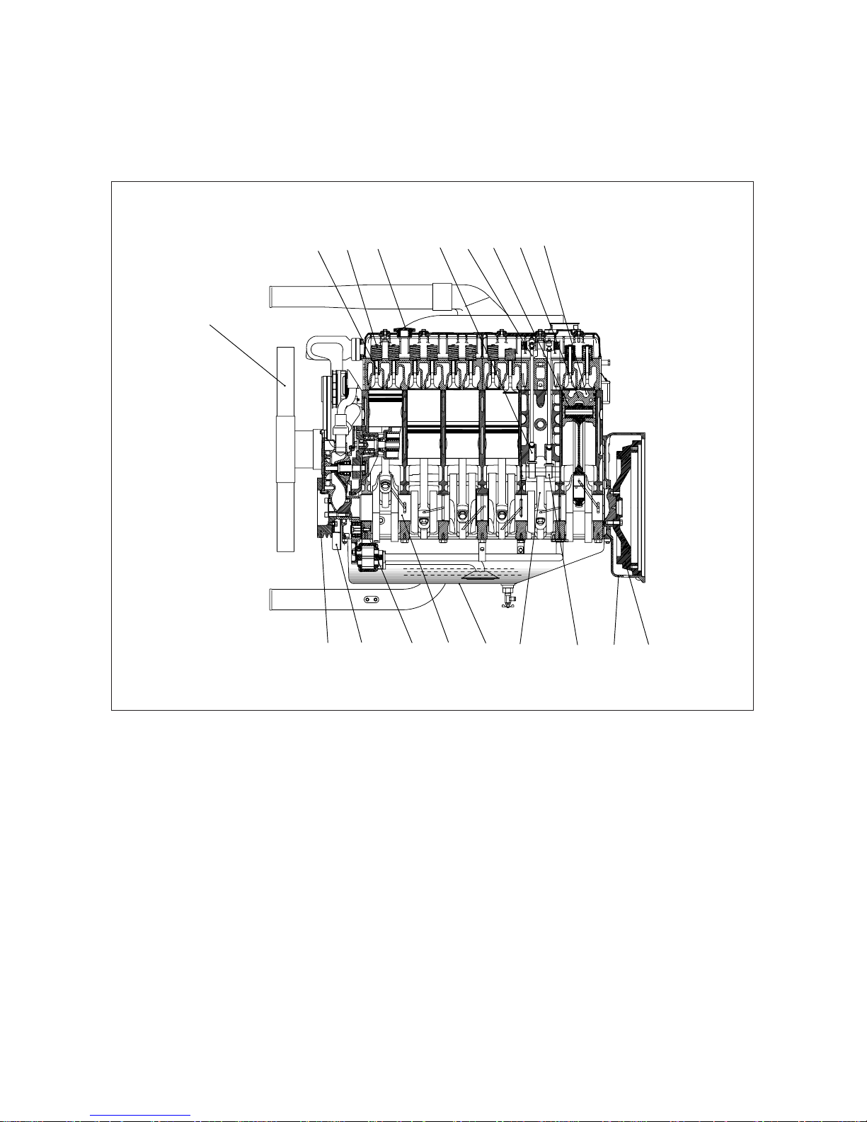
2.1.1. Engine sectional view (Longitudinal)
- 5 -
EA8M1002
1
2
10 11 12 13 14 15 16 17 18
3 4 56789
1. Cooling fan
2. Exhaust valve
3. Valve spring
4. Oil filter
5. Tappet
6. Push rod
7. Piston pin
8. Piston
9. Combustion chamber
10. Crankshaft pulley
11. Vibration damper
12. Oil pump
13. Crankshaft
14. Oil pan
15. Connecting rod
16. Camshaft
17. Flywheel housing
18. Flywheel
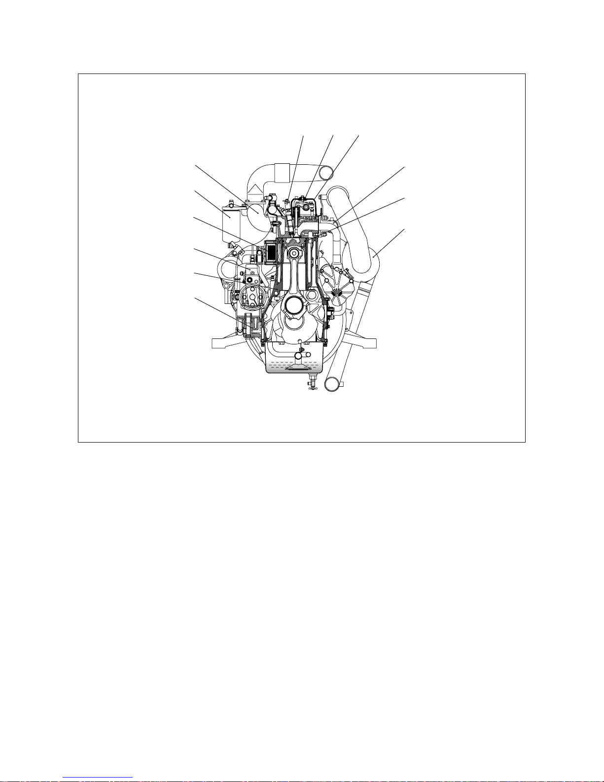
2.1.2. Engine sectional view (Cross)
- 6 -
EA8M1003
1
2
10
11
12
3
4
5
6
789
1. Intake manifold
2. Fuel filter
3. Oil cooler
4. Injection pump
5. Cylinder block
6. Oil filter
7. Injection nozzle assembly
8. Rocker arm
9. Cylinder head cover
10. Exhaust manifold
11. Piston ring
12. Turbocharger
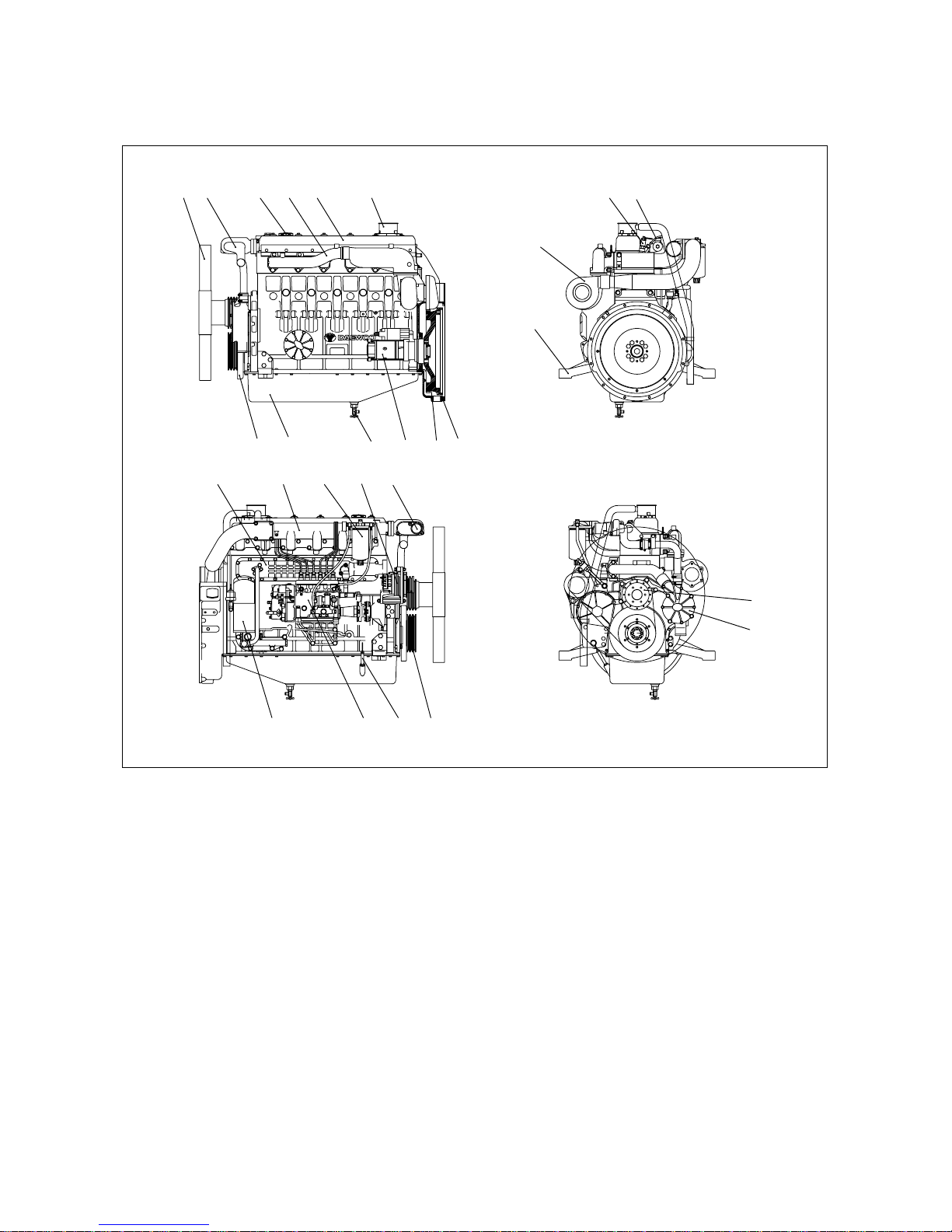
2.1.3. Engine assembly views
1) DE12T
- 7 -
EA8M1004
1 2 3 12 4 27 13 18
5
22
23
16
14 20 21 26
25
24
17 15 197
11 10869
1. Cooling fan
2. Cooling water pipe
3. Oil filler cap
4. Cylinder head cover
5. Turbocharger
6. Oil drain valve
7. Alternator
8. Oil pan
9. Starter
10. Flywheel housing
11. Flywheel
12. Exhaust manifold
13. Injection nozzle assembly
14. Oil filter
15. Fuel filter
16. Oil cooler
17. Intake manifold
18. Injection pipe
19. Thermostat
20. Injection pump
21. Oil level gauge
22. Mounting bracket
23. Vibration damper
24. Water pump
25. Fan drive
26. Crankshaft pulley
27. Breather
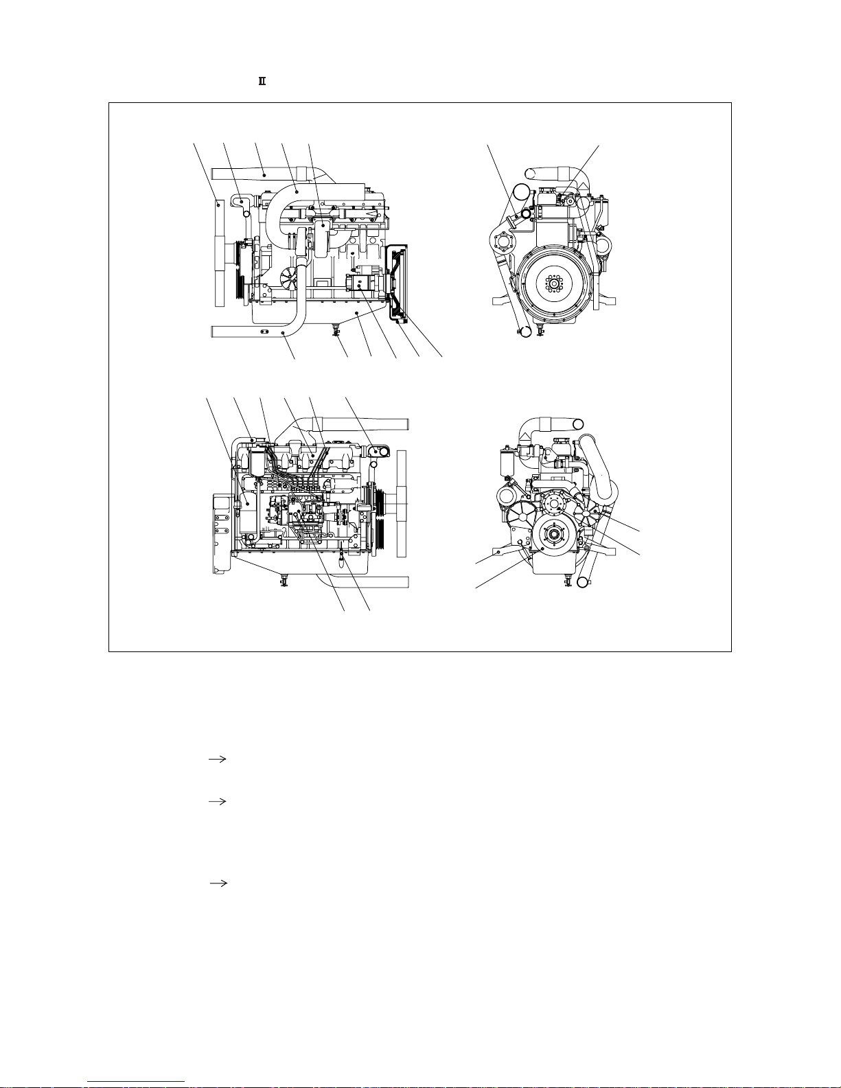
2)
P126TI / P126TI-
- 8 -
EA8M1005
12
768910
14 15 16 17 18 19
20 21
22
23
24
25
11
345 12 13
1. Cooling fan
2. Cooling water pipe
3. Air pipe
(Intercooler Intake manifold)
4. Air pipe
(Air cleaner Turbocharger)
5. Turbocharger
6. Oil drain valve
7. Air pipe
(Intercooler Intake manifold)
8. Oil pan
9. Starter
10. Flywheel housing
11. Flywheel
12. Exhaust manifold
13. Injection nozzle assembly
14. Oil filter
15. Breather hose
16. Oil cooler
17. Intake manifold
18. Injection pipe
19. Thermostat
20. Injection pump
21. Oil level gauge
22. Mounting bracket
23. Vibration damper
24. Water pump
25. Fan drive

2.2. Engine Specification
- 9 -
Engine Model
Items
DE12T P126TI
P126TI-1 P126TI-
Engine type
Water-cooled, 4 cycle in-line
Water-cooled, 4 cycle in-line type
type Turbo charged
Turbo charged & intercooled
Combustion chamber type Direct injection type
Cylinder liner type Replaceable dry liner
Timing gear system Gear driven type
No. of piston ring Compression ring 2, oil ring 1
No. of cylinder-bore
x
stroke (mm) 4 - 123 x 155
Total piston displacement (cc) 11,051
Compression ratio 17.1 : 1
Engine dimension
(length xwidth xheight) (mm)
1,365.5 x 870 x 1,046
1,383 x 870 x 1,207
Engine weight (kg) 930 910
Rotating direction (from flywheel) Counter clockwise
Fuel injection order 1 - 5 - 3 - 6 - 2 - 4
Fuel injection timing (B.T.D.C static) 12
¡
16
¡
16
¡
16
¡
Injection pump type Zexel in-line ÒPÓ type
Governor type
Mechanical governor type(RSV)
Electric governor type(Ghana Control)
Injection nozzle type
Multi-hole type (5 hole)
Multi-hole type (5 hole)
Fuel injection pressure (kg/cm2) 220 1st : 160, 2nd : 220
Compression pressure (kg/cm2) 28 (at 200 rpm)
Condition
50Hz 60Hz 50Hz 60Hz 60Hz 60Hz
(1,500rpm) (1,800rpm) (1,500rpm) (1,800rpm) (1,800rpm) (1,800rpm)
Continuous
--
280PS 336PS
--
Power (ISO 3046)
(206kW) (247kW)
Prime
205PS 245PS 328PS 378PS 356PS
-
(151kW) (180kW) (241kW) (278kW) (262kW)
Stand by
226PS 270PS 370PS 405PS 392PS 465PS
(166kW) (199kW) (272kW) (298kW) (288kW) (342kW)
I
ntake and exhaust valve
clearance (at cold) (mm)
0.3
Intake valve
Open at 18
¡
(B.T.D.C)
Close at 34¡(A.B.D.C)
Exhaust valve
Open at 46
¡
(B.B.D.C)
Close at 14¡(A.T.D.C)
Lubrication method Full forced pressure feed type
Oil pump type Gear type driven by crankshaft
Oil filter type Full-flow, Cartridge type
Lubricating oil capacity (max./min.) (lit) 23/20
Oil cooler type Water cooled
Water pump Gear driven impeller type
Cooling Method Pressurized circulation
Cooling water capacity (engine only) (lit) 19
Thermostat type Wax pallet type (71 ~ 85
¡
C)
Alternator voltage - capacity (V - A) 24 - 45
Starting Motor voltage
- output (V - kW)
24 - 6.0

3. Technical Information
3.1. Engine Model and Serial Number
The engine model and serial number is locat-
ed on the engine as illustrated. These num-
bers are required when requesting warranty
and ordering parts. They are also referred to
as engine model and serial number because
of their location.
¥
Engine serial No. (example 1 : DE12T)
EBHOA300001
Serial No.
ProductionYear(2003)
Engine Model Suffix
¥
Engine serial No. (example 2 : P126TI)
EDIOA300001
Serial No.
ProductionYear(2003)
Engine Model Suffix
¥
Engine serial No. (example 3: P126TI- )
EDIOC300001
Serial No.
ProductionYear(2003)
Engine Model Suffix
- 10 -
Engine Number
EA8O3001
EA9O2002
DAEWOO HEAVY INDUSTRIES LTD.
MODEL
SPEED 1500/1800 rpm
STAND-BY
PRIME
BORE
mm
mm
cc
STROKE
VOLUME
YEAR
SERIAL NUMBER
EA9O2003
IMPORTANT ENGINE INFORMATION
DAEWOO HEAVY INDUSTRIES LTD.
ENGINE AND MATERIAL DIV.
6, MANSECOK-DONG, DONG-GU
INCHEON, KOREA
TYPE 2-D DIESEL FUEL.
THIS DAEWOO HEAVY-DUTY DIESEL MODEL
EPA AND CARB STANDARDIZED ENGINE FAMILY DESIGNATION IS
TUNE-UP SPECIFICATIONS AND ADJUSTMENTS
IS CERTIFIED TO OPERATE ON
< Name Plate : General >
< Name Plate : EPA & CARB >

3.2. Engine Type
The Engines DE12T/ P126TI / P126TI- are in-line vertical water-cooled 6-cylinder four-stroke
diesel engines with direct injection. DE12T is turbo-charged engine, and P126TI / P126TI-
models are turbo-charged and inter-cooled engine.
3.2.1. Cylinder block
The cylinder block is a single piece of alloy cast iron. To increase its stiffness, it is extended to
a level below the crankshaft center line. The engine has replaceable dry cylinder liners and
individual cylinder heads with struck-in valve seat rings and replaceable valve guides,
3.2.2. Piston con-rod / crankshaft
The forged crankshaft is a ingrate type (Counterweight is integrated with crank shaft body).
Radial oil seal on crankshaft and flywheel are provided to seal the flywheel housing inside pen-
etrations.
The con-rods (connecting rods) are die-forged, diagonally split and can be removed through
the top of the cylinders together with the pistons. Crankshaft and connecting rods run in steel-
backed lead bronze ready-to fit type bearings.
- 11 -

3.3. Engine Timing
Camshaft, oil pump and injection pump are driven by a gear train arranged at the front end.
3.4. Valves
The overhead valves are actuated via chilled cast iron tappets, push rods and rocker arms from
the camshaft.
- 12 -
EA8O3002
Injection pump gear
(Z = 72)
Water pump gear
(Z = 29)
Camshaft gear
(Z = 72)
Crankshaft gear
(Z = 36)
Oil pump idle gear
(Z = 31)
Oil pump drive gear
(Z = 32)
Idle gear
(Z = 52)
- 13 -
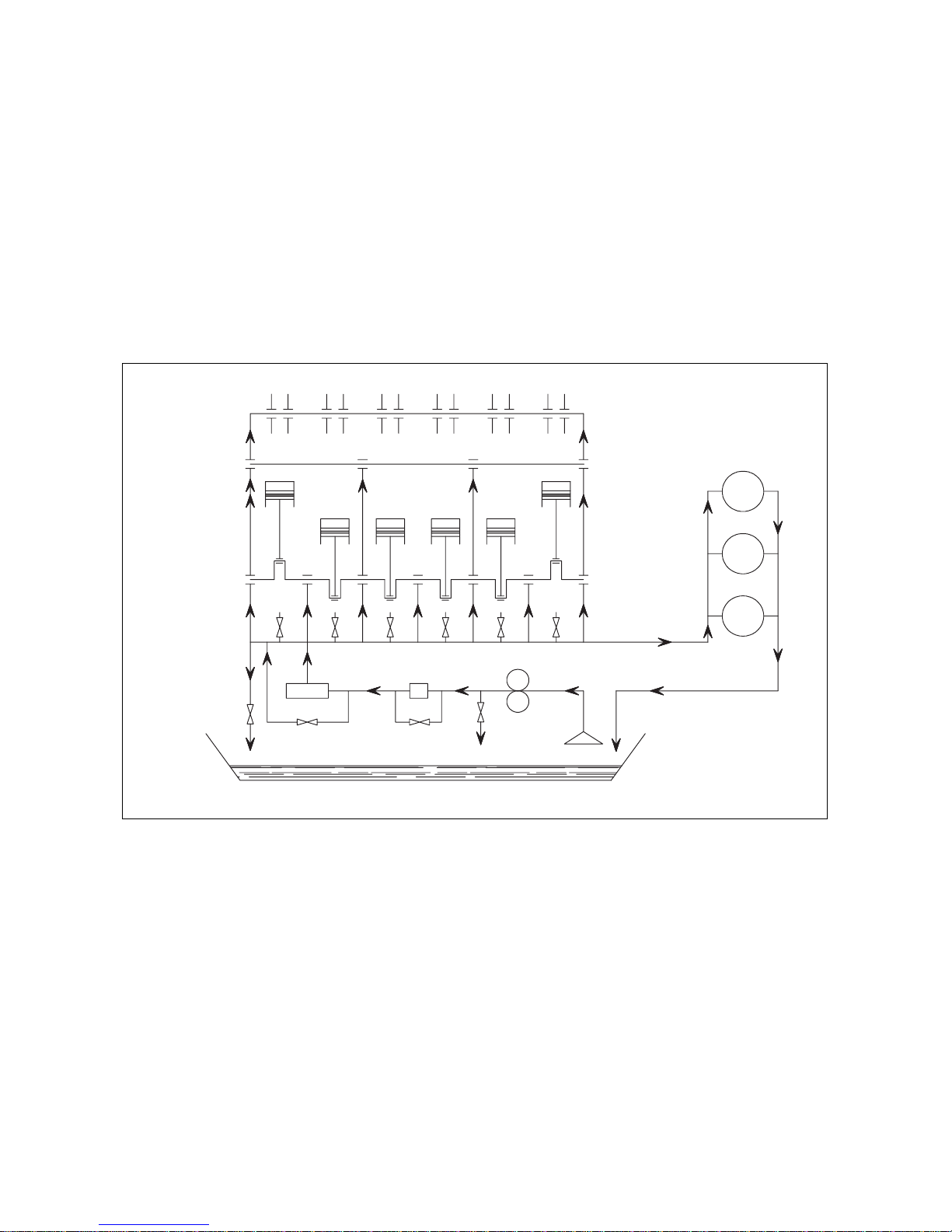
3.5. Lubrication System
The engine is equipped with force-feed lubrication.
The pressure is produced by a gear pump whose drive gear is in direct mesh with the crankshaft
gear at the front end of cylinder block.
The oil pump draws the oil from the oil sump and delivers it through the oil cooler and oil filter
to the main distributor gallery and from there to the main bearings, big-end bearings and
camshaft bearings as well as to the small-end bearings and the rocker arms.
The injection pump and the turbocharger are also connected to the engine lubricating system.
The cylinder walls and timing gears are splash lubricated.
Each cylinder has an oil jet provided for cooling the underside of the pistons.
The lube oil is cleaned in a full-flow oil filter.
Rock arm
Cam shaft
Con-rod bearing
Main bearing
Main gallery
Relief valve
4.4 bar
Valve : 5 bar
Cooler
Piston
Oil pump
Valve : 10 bar
Oil jet valve
1.3 bar
W/P
BRG.
I/P
T/C
Filter
Valve : 3 bar
ED5OM001
3.5.1. Oil cooler
An oil cooler is provided between the oil filter and the cylinder block. This cooler is a flat tube
type with turbulence inserts and operated by the coolant.
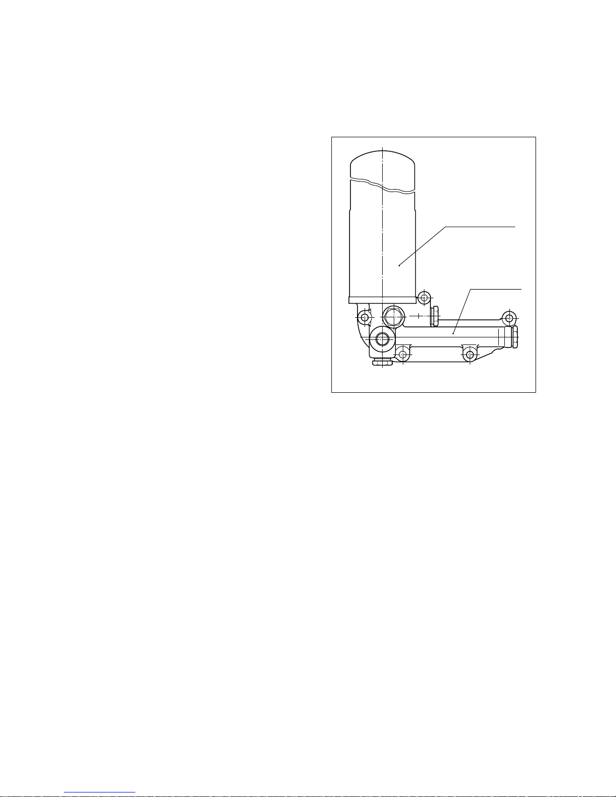
3.5.2. Oil filter
Check for oil pressure and oil leaks, and
repair or replace the oil filter if necessary.
Change the oil filter cartridge simultaneous-
ly at every replacement of engine oil.
3.6. Air Cleaner
In case that elements are deformed, damaged or if the air cleaner has a crack, replace it.
By the definite interval, the elements must be cleaned and replaced.
- Cleaning of air cleaner element: Every 200 hours.
- Changing of air cleaner element: Every 400 hours.
3.7. Fuel System
The fuel is delivered by the fuel feed pump via the fuel filter to the injection pump and from there
to the injection nozzles.
The fuel is sprayed into the cylinders through nozzles fitted in screw-fit injection nozzle holders
in the cylinder heads.
Excessively delivered fuel and leak fuel from the nozzle flow through the return pipe back to the
tank.
A strainer is arranged ahead of the fuel feed pump.
- 14 -
Oil filter (Cartridge)
Oil filter head
EQM4010I
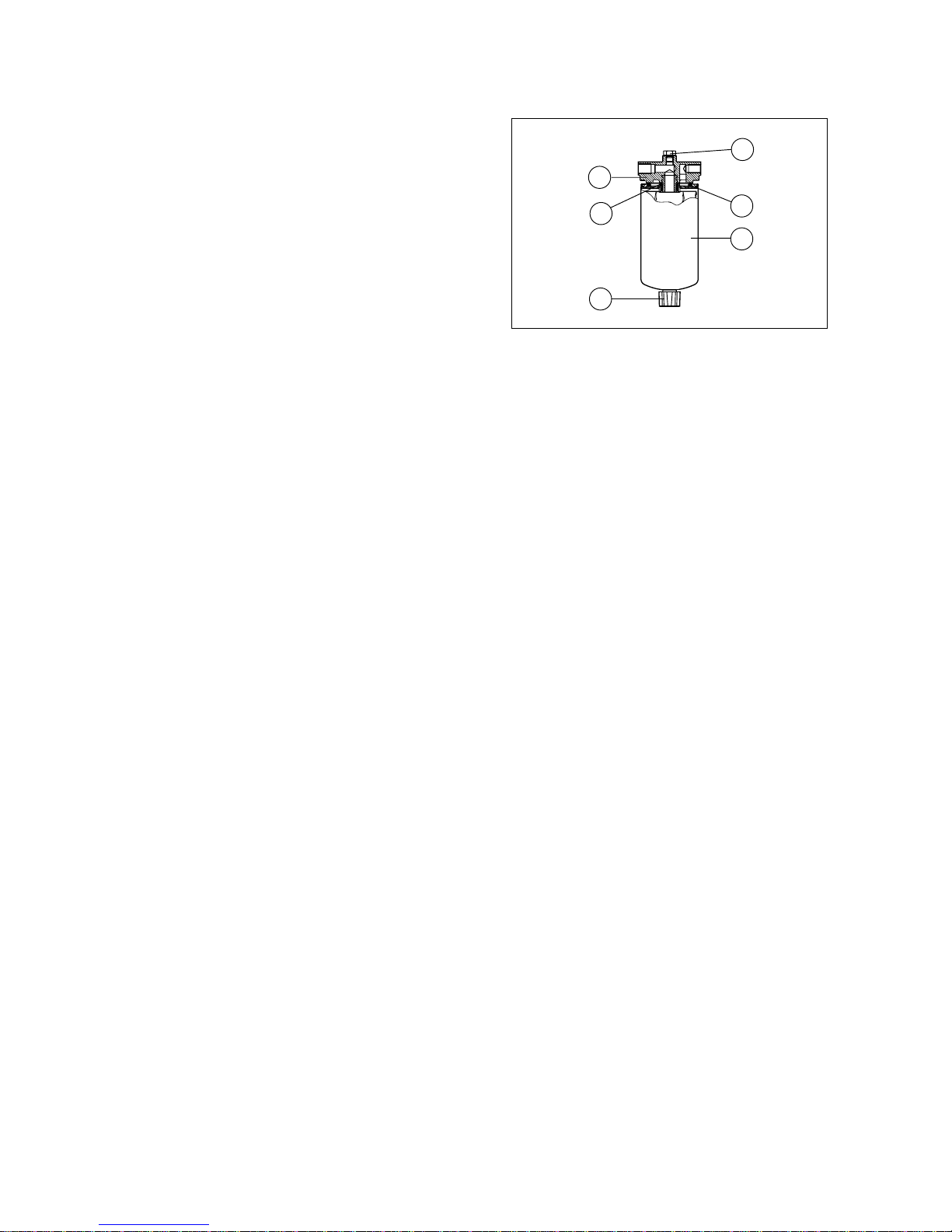
3.7.1. Fuel filter
This fuel filter has two functions not only oil
filtering but also water separating.
Before entering the suction chamber of the
injection pump, the fuel is cleaned in a
strainer of fuel feed pump and a fuel filter.
Drain water in cartridge with loosening the
cock under filter manually (6) from time to
time.
The fuel filter should be replaced at every
400 hours.
3.7.2. Fuel requirements
DAEWOO marine diesel engines was designed to use Number 2-D diesel fuel or equivalent
that meets specification DIN 51601-DK. For maximum fuel economy, Number 2-D fuel when-
ever possible. When temperatures are below -7
û
C(20ûF), use Number 1-D fuel. If Number 1-D
fuel is not available, the mixture of one kerosene to two gallons of Number 2-D fuel can be
used. Once kerosene has been added, the engine should be run for several minutes to mix the
fuel.
3.7.3. How to select fuel oil
Fuel quality is an important factor in obtaining satisfactory engine performance, long engine
life, and acceptable exhaust emission levels. DAEWOO engines are designed to operate on
most diesel fuels marketed today. In general, fuels meeting the properties of ASTM
Designation D975 (grades 1-D and 2-D) have provided satisfactory performance.
The ASTM 975 specification, however, does not in itself adequately define the fuel character-
istics needed for assurance of fuel quality.
The properties listed in the fuel oil selection chart below have provided optimum engine per-
formance. Grade 2-D fuel is normally available for generator service. Grade 1-D fuel should
not be used in pleasure craft engines, except in an emergency.
- 15 -
1
5
2
3
4
6
EA2O4009

Fuel oil selection chart
#) Not specified In ASTM D 975
+) Differs from ASTM D 975
Note : 1.The cloud point should be 6
ûC
(10ûF) below the lowest expected fuel tem-
perature to prevent clogging of fuel fitters by crystals.
- 16 -
General Fuel ASTM No. 1 No. 2
DIN 51601
Classification Test ASTM 1-D ASTM 2-D
Gravity,ûAPI
#)
D 287 40 ~ 44 33 ~ 37 0.815 ~ 0.855
Flash Point
D 93 100 (38) 125 (52) 131 (55)
Min. ûF (ûC)
Viscosity, Kinematic
D 445 1.3 ~ 2.4 1.9 ~ 4.1 1.8 ~ 10
CST 100 ûF (40 ûC )
Cloud Point ûF
#)
D 2500 See Note 1) See Note 1) See Note 1)
Sulfur Content
D 129 0.5 0.5 0.15
wt%, Max.
Carbon Residue
D 524 0.15 0.35 0.1
on 10%, wt%, Max.
Accelerated Stability
Total Insolubles D 2274 1.5 1.5
mg/100 ml, Max.
#)
Ash, wt%, Max. D 482 0.01 0.01
Cetane Number, Min.
+)
D 613 45 45 > 45
Distillation D 86
Temperature,
ûF(û
C)
IMP, Typican
#)
350(177) 375(191)
10% Typical
#)
385(196) 430(221)
50% Typical
#)
45(218) 510(256) 680(360)
90%
+)
500 (260) Max. 625(329) Max.
End Point
#)
550(288) Max. 675(357) Max.
Water & Sediment
D 1796 0.05 0.05 0.05
%, Max.
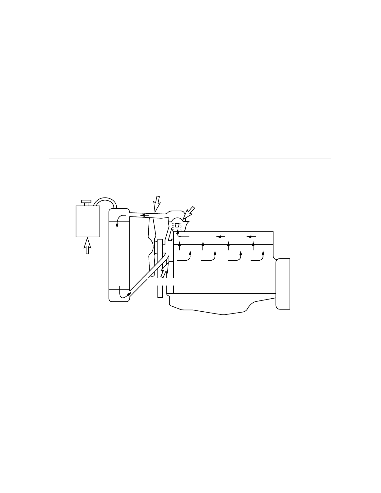
3.8. Cooling System
The engine has a liquid-cooling system. The fresh water pump is a maintenance-free by gear
from the crankshaft.
Depending on the agreed extent of delivery and the design of the engine, the coolant circuit can
be equipped with temperature monitors which, in the event of loss of coolant, shut the engine
down.
¥
Check the coolant level of the expansion tank by removing the expansion tank filler cap, and
add coolant if necessary.
¥
When injecting antifreeze solution, first drain out the old coolant from the cylinder block and
radiator, and then clean them with cleaning solution.
¥
Be sure to mix soft water with antifreeze solution.
- 17 -
Water pipe
Reserve tank
Thermostat
EJM4001I
Cylinder head
Cylinder block
Water pump
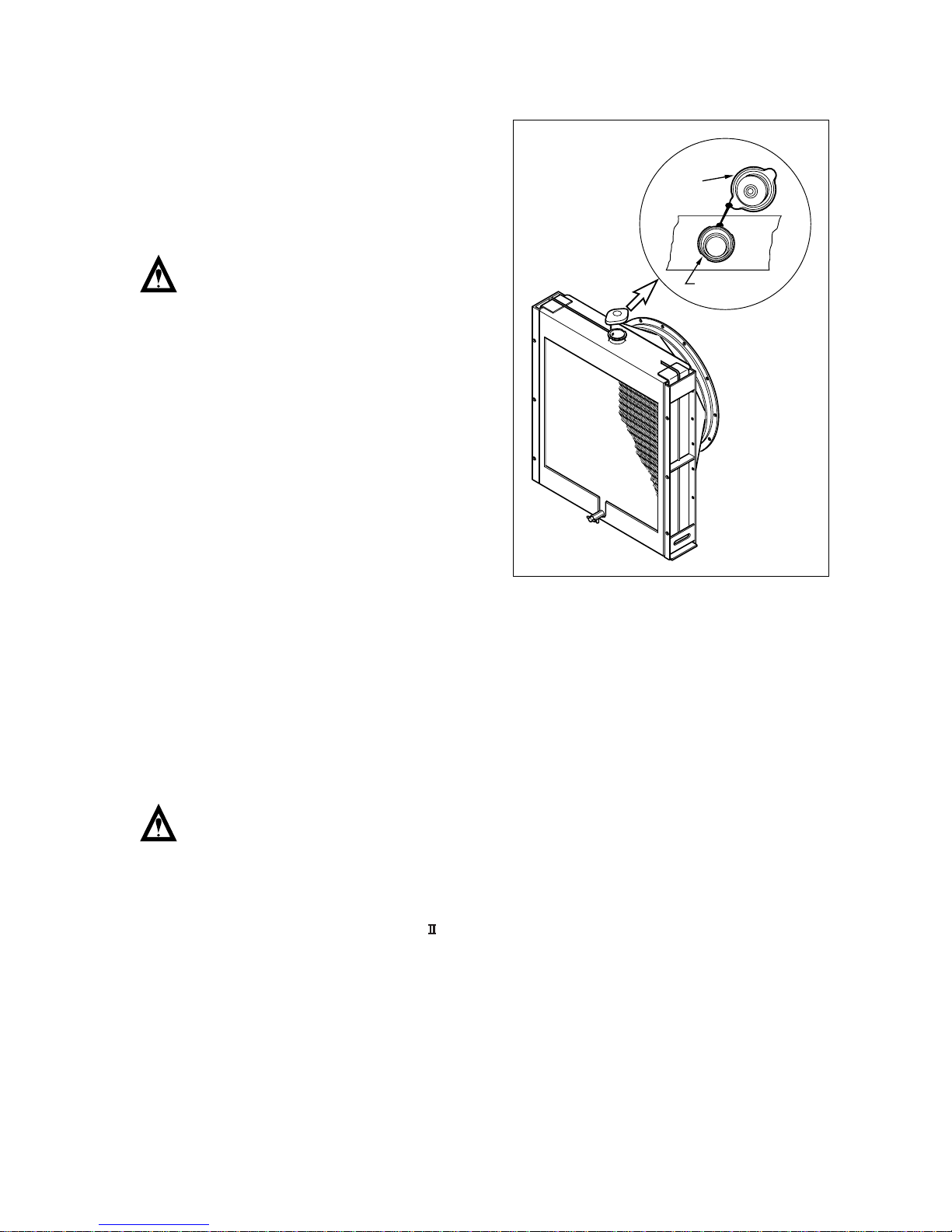
3.8.1. Coolant pressure cap
Check the pressure valve opening pressure
using a expansion tank cap tester. Replace
the filler cap assembly if the measured valve
does not reach the specified limit. (pressure
valve opening pressure : 0.9 kg/cm
2
)
Note : Because it is dangerous to open
the pressure cap quickly when
coolant is hot, after lowering the
inside pressure of the tank by
slow-opening at first open it fully.
3.8.2. Cooling water
¥
Regarding the cooling water that is to be used for engine, the soft water not the hard water
must be used.
¥
The engine cooling water can be used diluting it with antifreezing solution 40% and the addi-
tive for rust prevention (DCA4) 3 ~ 5 %.
¥
The density of above solution and additive must be inspected every 500 hours to maintain it
properly.
Note : The proper density control of antifreezing solution and rust preventing additive will
be able to prevent the rusting effectively and maintain the stable quality of engine.
For the improper control might give the fatal damage to the cooling water pump and
cylinder liners, detail care is needed.
¥
Since DE12T , P126TI and P126TI- cylinder liner is dry type, particularly the cooling water
control should be applied thoroughly.
¥
The density of antifreezing solution and additive for rust prevention is able to be confirmed by
the cooling water test kit. (Fleetguard CC2602M)
¥
How to use the cooling water test kit
1) When the cooling water temp. of engine is in the range of 10 ~ 55
¡
C, loosen the plug for
cooling water discharge and fill the plastic cup about a half.
- 18 -
Rediater Cap
Rediater
EA5O3002
Note : In taking the cooling water sample, if the water in auxiliary tank were taken, it is hard
to measure the accurate density. Take the cooling water sample necessarily loosen-
ing the cooling water discharge plug.
2) At the state of a test paper soaked in the sampled water, after taking the paper out through
water agitation, shake off the water.
3) Wait for about 45 sec. till the color change of test paper.
Note : However, it should not elapse longer than 75 sec, and if it did, the hue would change.
4) Make the numerical value by comparing the test paper which hue has changed with the
color list of label on storage bottle.
5) By comparing the hue changed into yellowish green or so with the green color indication of
test paper storage bottle, confirm the density. (Then, the density indication must be in the
hue range of 33% to 50%).
6) The brown at the middle of test paper and the lower pink color indication represent the addi-
tive state for rust prevention, and the proper range is that the meeting numerical value of
brown (vertical) and pink color (horizontal) locates in the range of 0.3 to 0.8 at the color list
of label on the test paper storage bottle.
7) In case of less than 0.3, replenish the additive for rust prevention (DCA4), and in case of
more than 0.8, pour out the cooling water about 50% and then readjust the density after
refilling with clean fresh water.
¥
Amount of Anti-freeze in winter
- 19 -
Ambient
Cooling water (%) Anti-freeze (%)
Temperature (ûC)
Over -10 85 15
-10 80 20
-15 73 27
-20 67 33
-25 60 40
-30 56 44
-40 50 50
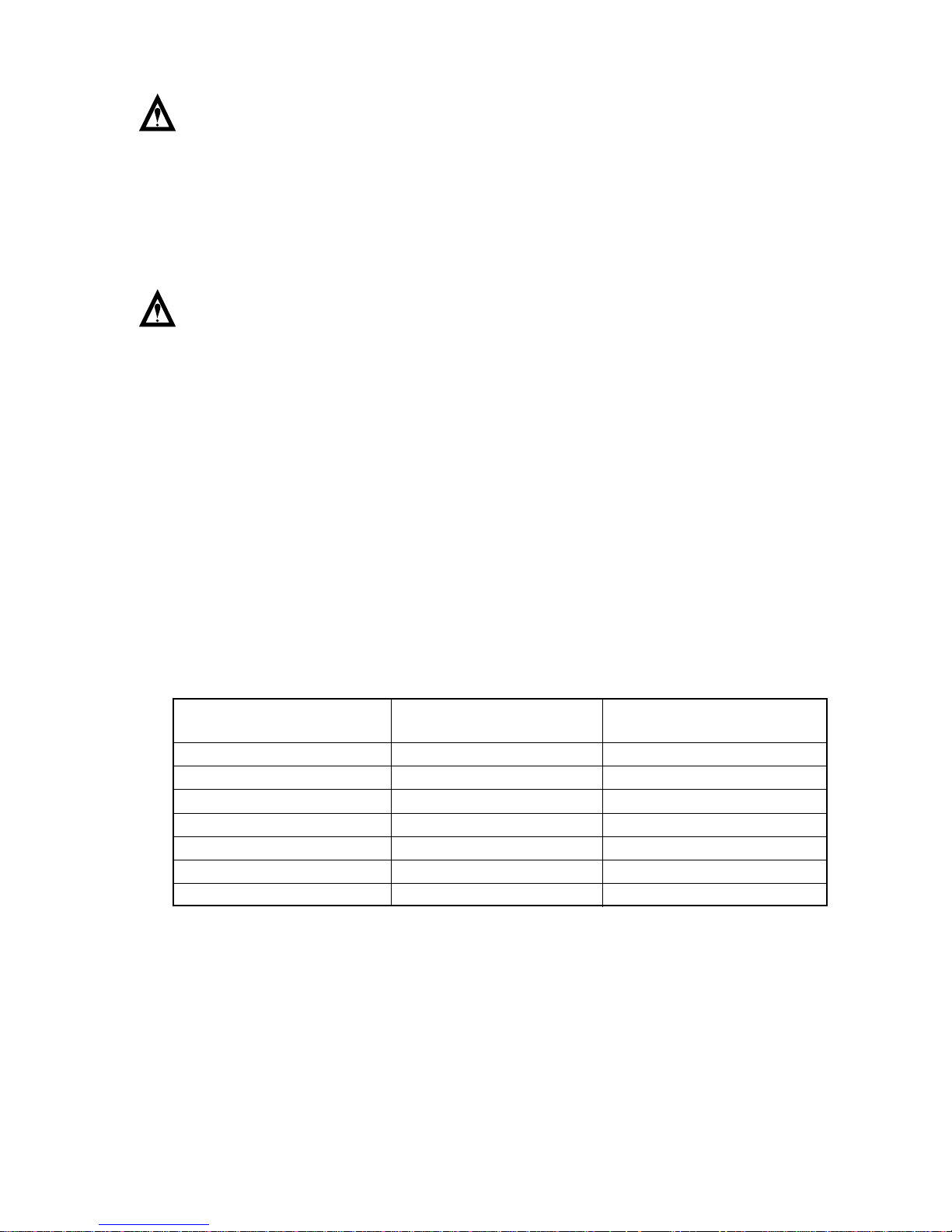
3.9. V-belt Tension Check and Adjust
By the finger-pressure the belt is pressed by
10mm ~ 15mm between the fan pulley and
the alternator pulley in normal condition. For
the adjustment of the tension, loosen the
adjusting bolts which support the alternator,
adjust the tension and tighten the bolts
again.
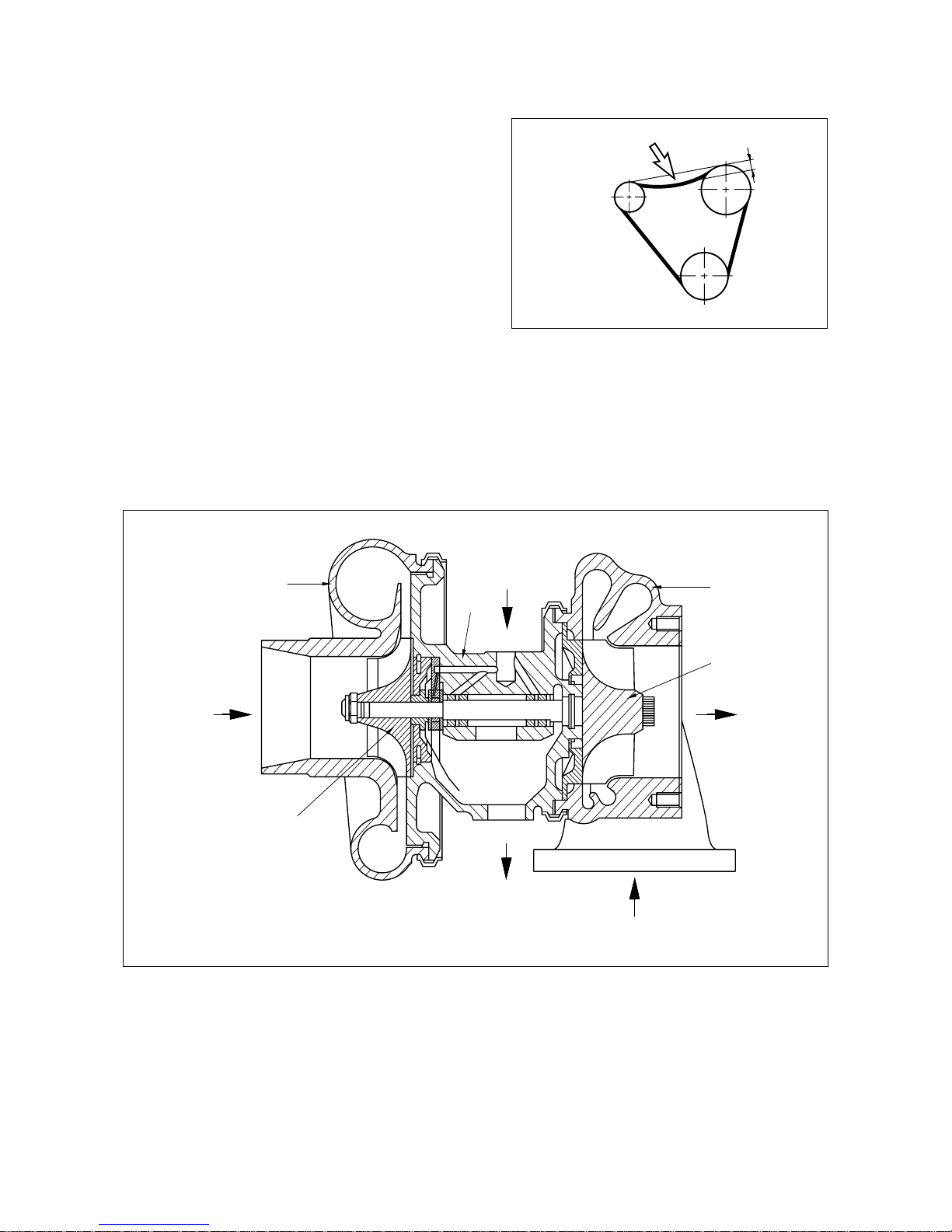
3.10. Turbocharger
The exhaust gases of the engine are passed through the turbine rotor of the turbocharger. Air
compressor impeller mounted on the same shaft draws in fresh air and delivers it at a higher
pressure to the cylinders.
The turbocharger is naturally air-cooled. Lubrication of the main bearing is by oil under pres-
sure from the engine lubricating system.
1. Compressor casing A. Air inlet
2. Turbine casing B. Gas outlet
3. Compressor wheel C. Gas inlet
4. Impeller D. Oil supply
5. Turbine E. Oil return
- 20 -
EA8O3005
15mm
Fan
Pulley
Press hear
Crank Pulley
Alternator
Pulley
V-belt
C
5
3
2
B
E
4
1
A
D
EA6O3004
here
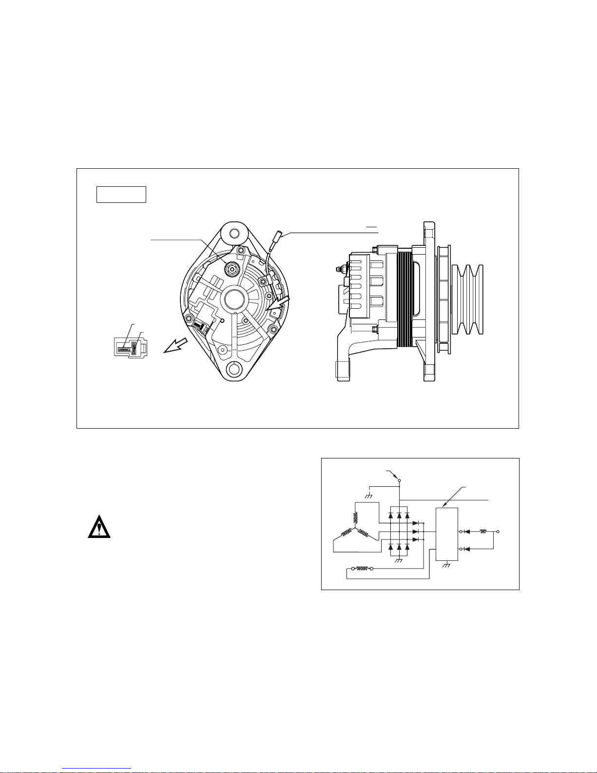
3.11. Electrical Equipment
3.11.1. Alternator
The alternator is fitted with integral silicon rectifiers. A transistorized regulator mounted on the
alternator body interior limits the alternator voltage. The alternator should not be operated
except with the regulator and battery connected in circuit to avoid damage to the rectifier and
regulator.
The alternator is maintenance-free, never-
theless, it must be protected against dust
and, above all, against moisture and water.
Operate the alternator according to the
instructions given in the chapter.
- 21 -
To Battery +
EA8O3007
Regulator
RL = 150~250 OHM
RL
EA8O3006
P-TAB : KET GP 890545
TACHOMETER CHARGE INDICATOR
ALDO SYSTEM FREQUENCY =
M6 x 1.0 THREAD
BATTERY TERMINAL
RPM
10
"L" Terminal
"R" Terminal
CONNECTOR HOUSING
KET MG 620042
TERMINAL
KET ST 740254
24V x45A
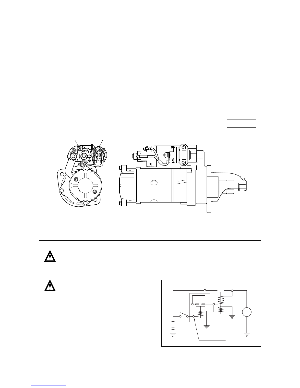
3.11.2. Starter motor
The sliding-gear starter motor is flanged to the rear of the flywheel housing on the left-hand
side. When the starting key switch is turned on, the starter motor pinion flies out and engages
the ring gear of the flywheel. Then the main contact is closed, current flows, and the engine
is started. After the engine starts, the pinion automatically returns to its initial position when
the starting key switch is released. Once the engine starts, the starting key switch should be
released immediately. Otherwise, the starter motor may be damaged or burned out.
In case of repairing the engine dip the pinion of the starter and ring gear into the fuel and
remove the corrosion with brush. After that apply the grease on them to protect the corrosion.
Whenever you clean the starter, always pay attention not to occur the electric short due to
entering the water.
Always protect starter motor against moisture.
Warning : Always disconnect the bat-
tery earth cable before start-
ing work on the electrical sys-
tem. Connect up the earth
cable last, as there is other-
wise a risk of short-circuits.
- 22 -
TERMINAL "B"
M10 x P1.5
TERMINAL S/W
M5 x P0.8
EA8O3008
24V x 6.0kW
2.5A(20oC 24V)
M
EA8O3009
Motor
S/W
KS
S/W
S/W
S
B
B
W
24V x6.0kW

4. Commissioning and Operation
4.1. Preparation
At the time of initial commissioning of a new or overhauled engine make sure to have observed
the ÒTechnical Information for the installation DAEWOO generator enginesÓ.
¥
Oil filler neck on cylinder head cover
Before daily starting of the engine, check the fuel, coolant and oil level, replenish if necessary.
The notches in the dipstick indicate the highest and lowest permissible oil levels
The oil required in the sump is specified in the ÒEngine SpecificationÓ.
Note : The oil required to fill the oil fillers and pipes depends upon the engine and use and
must be determined individually at the time of initial commissioning. (Make the Max
and Min. marks of the determined quantity on the oil level gauge.)
¥
Cleanliness
Ensure outmost cleanliness when handling fuels, lubricants and coolants.
4.2. Breaking-in
4.2.1. Operation of a new engine (Break-In)
Because the sliding surfaces of a new engine are not lapped enough, the oil film can be
destroyed easily by overload or overspeed and the engine life-time may be shortened.
Therefore the following things must be obeyed by all means.
Up to the first 50 hours
¥
Engine should be run at fast idling until the temperature of the engine becomes normal oper-
ating condition.
¥
Overload or continuous high speed operation should be avoided.
¥
High speed operation with no load should be prevented.
¥
Abrupt start and stop of the engine should be avoided.
¥
Engine speed must be under 70% of its maximum speed.
¥
Maintenance and inspection must be accomplished thoroughly.
- 23 -
4.2.2. Check points for break-in
During the break-in (the initial running of the engine) period, be particularly observant as fol-
lows:
a) Check engine oil level frequently. Maintain oil level in the safe range, between the Òmin.Ó and
Òmax.Ó marks on dipstick.
Note : If you have a problem getting a good oil level reading on dipstick, rotate dipstick 180
û
and re-insert for check.
b) Watch the oil pressure warning lamp. If the lamp blinks, it may be the oil pick-up screen is
not covered with oil. Check oil dipstick. Add oil to the oil pan, if required. Do not overfill. If
level is correct and the status still exists, see your DEALER for possible switch or oil pump
and line malfunction.
Note : Oil pressure will rise as RPM increases, and fall as RPM decreases. In addition, cold
oil will generally show higher oil pressure for any specific RPM than hot oil. Both of
these conditions reflect normal engine operation.
c) Watch the engine water temperature gauge and be sure there is proper water circulation.
The water temperature gauge needle will fluctuate if water level in expansion tank is too low.
At the end of the break-in period, remove break-in oil and replace the oil filter. Fill oil pan
with recommended engine oil. Refer to following table.
<Engine Oil capacity>
4.2.3. Operating after break-in
When starting a cold engine, always allow the engine to warm up gradually. Never run the
engine at full throttle until the engine is thoroughly warmed up. Be sure to check the oil level
frequently during the first 50 hours of operation, since the oil consumption will be high until the
piston rings are properly seated.
- 24 -
Oil pan (only)
DE12T 23 liter
P126TI/P126TI- 23 liter

4.3. Inspections after Starting
During operation the oil pressure in the engine lubrication system must be monitored. If the mon-
itoring devices register a drop in the lube oil pressure, switch off the engine immediately.
And the charge warning lamp of the alternator should go out when the engine is running.
¥
Do not disconnect the battery or pole terminals or the cables!
¥
If, during operation, the battery charge lamp suddenly lights up, stop the engine immediately
and remedy the fault in the electrical system!
¥
Engine should be stopped if the color, the noise or the odor of exhaust gas is not normal.
¥
Confirm the following things through warning lamps and gauge panel.
4.3.1. Pressure of lubricating oil
The normal pressure comes up to 1 kg/cm
2
(1.0 bar) at idling and 3 ~ 5 kg/cm
2
(3.0 ~ 4.9 bar)
at maximum speed. If the pressure fluctuates at idling or does not reach up to the expected
level at high speed, shut down the engine immediately and check the oil level and the oil line
leakage.
4.3.2. Temperature of cooling water
The cooling water temperature should be 71 ~ 85
û
C in normal operating conditions. Abnormally
high cooling water temperature could cause the overheating of engine and the sticking of cylin-
der components. And excessively low cooling water temperature increases the fuel consump-
tion, accelerates the wears of cylinder liners and shortens the engine life-time.
4.4. Operation in Winter Time
Pay special attention to the freezing of cooling water and the viscosity of lubricating oil.
4.4.1. Prevention against the freeze of cooling water
When not using anti-freeze, completely discharge the whole cooling water after engine run-
ning. The freeze of cooling water causes the fatal damages of the engine. Because the anti-
freeze is used to prevent cooling water from freeze, consult ÒThe amount of anti-freezeÓ.
4.4.2. Prevention against excessive cooling
Drop of thermal efficiency caused by excessive cooling increases fuel consumption, therefore
prevent the engine from excessive cooling. If the temperature of coolant does not reach to nor-
mal condition (71 ~ 85
û
C) after continuous operation, examine the thermostat or the other cool-
ing lines.
4.4.3. Lubricating oil
As cold weather leads to the rise of oil viscosity, engine speed becomes unstable after start-
ing. Therefore the lubricating oil for winter should be used to prevent this unstability. Refer to
ÒLubricating System sectionÓ.
- 25 -

4.5. Tuning the Engine
The purpose of an engine tune-up is to restore power and performance thatÕs been lost through
wear, corrosion or deterioration of one or more parts or components. In the normal operation of
an engine, these changes can take place gradually at a number of points, so that itÕs seldom
advisable to attempt an improvement in performance by correction of one or two items only. Time
will be saved and more lasting results will be obtained by following a definite and thorough pro-
cedure of analysis and correction of all items affecting power and performance.
Economical, trouble-free operation can better be ensured if a complete tune-up is performed
once every years, preferably in the spring. Components that affect power and performance to be
checked are:
¥
Components affecting fuel injection ;
Nozzle, delivery valve, fuel filter, water separator, etc.
¥
Components affecting Intake & exhaust ;
Air filter, inter-cooler, turbo, silencer, etc.
¥
Components affecting lubrication & cooling ;
Air & oil filter, anti- freeze, etc.
- 26 -
 Loading...