

DTM-01
USER’S GUIDE
©All Rights Reserved

DTM-01 User’s Guide
Rev.: 1.0
+Update: 26/11/18
Rev. 1.0
Page 2 of 29
This page contains confidential information, which is protected by copyright and is proprietary to DIV
No part of this document may be used, copied, disclosed or conveyed to another party without prior written consent of DIV
Revision History
Revision
Issue Date
Author
Scope
1.0
2018/11/16
Ahn.H.W
Initial Release

DTM-01 User’s Guide
Rev.: 1.0
+Update: 26/11/18
Rev. 1.0
Page 3 of 29
This page contains confidential information, which is protected by copyright and is proprietary to DIV
No part of this document may be used, copied, disclosed or conveyed to another party without prior written consent of DIV
Contents
1 WARNINGS FOR SAFETY OPERATION ................................................................ 5
2 INTRODUCTION ...................................................................................................... 6
3 OVERVIEW .............................................................................................................. 7
3.1 Components ................................................................................................................................................... 7
3.2 Connection Diagram ................................................................................................ ................................ ...... 8
3.3 Features .......................................................................................................................................................... 9
4 HARDWARE DESCRIPTIONS ............................................................................... 10
4.1 DTM-01.......................................................................................................................................................... 10
4.1.1 Status LED .......................................................................................................................................... 12
4.1.2 DIP Switch ........................................................................................................................................... 13
4.1.3 SIM Socket .......................................................................................................................................... 13
4.1.4 WIFI Registration Button ................................................................................................................... 14
4.1.5 Reset Button........................................................................................................................................ 14
4.2 WIFI Antenna ................................................................................................................................................ 14
4.3 3G Antenna ................................................................................................................................................... 15
4.4 GPS Antenna ................................................................................................................................................ 17
4.5 Shock Sensor Module ................................................................................................................................. 18
4.6 Internal Battery ............................................................................................................................................. 19
5 HOW TO USE......................................................................................................... 20
5.1 User Registration ......................................................................................................................................... 20
5.2 3G Mode Operation ................................................................................................ ..................................... 20
5.3 WIFI Mode Operation .................................................................................................................................. 20
5.3.1 How to connect ..................................................................................................................................... 21
5.3.2 WIFI Manual Registration .................................................................................................................... 26
6 LIMITED WARRANTY ............................................................................................ 29

DTM-01 User’s Guide
Rev.: 1.0
+Update: 26/11/18
Rev. 1.0
Page 4 of 29
This page contains confidential information, which is protected by copyright and is proprietary to DIV
No part of this document may be used, copied, disclosed or conveyed to another party without prior written consent of DIV
Figure
FIGURE 1 LIN-Q SYSTEM .................................................................................................................................. 6
FIGURE 2 PACKAGE COMPONENT ................................................................................................................. 7
FIGURE 3 CONNECTION DIAGRAM ................................................................................................................ 8
FIGURE 4 DTM-01 TERMINAL ........................................................................................................................ 10
FIGURE 5 STATUS LED ................................................................................................................................... 12
FIGURE 6 DIP SWITCH ..................................................................................................................................... 13
FIGURE 7 SIM CARD SOCKET ........................................................................................................................ 13
FIGURE 8 WIFI EXTERNAL ANTENNA ......................................................................................................... 14
FIGURE 9 CONNECTING WIFI EXTERNAL ANTENNA .............................................................................. 14
FIGURE 10 3G EXTERNAL ANTENNA ......................................................................................................... 15
FIGURE 11 CONNECTING 3G EXTERNAL ANTENNA .............................................................................. 16
FIGURE 12 GPS ANTENNA ............................................................................................................................ 17
FIGURE 13 CONNECTING GPS ANTENNA ................................................................................................. 17
FIGURE 14SHOCK SENSOR MODULE ......................................................................................................... 18
FIGURE 15 BATTERY CONNECTING ........................................................................................................... 19
FIGURE 16 WIFI REGISTRATION 1 .............................................................................................................. 21
FIGURE 17 WIFI REGISTRATION 2 .............................................................................................................. 21
FIGURE 18 WIFI SEARCHING ....................................................................................................................... 22
FIGURE 19INSERT WIFI PASSWORD ........................................................................................................... 23
FIGURE 20 WIFI ACTIVATION ...................................................................................................................... 24
FIGURE 21 WIFI SET UP ................................................................................................................................. 24
FIGURE 22 CONNECTING ACCESS POINT ................................................................................................. 25
FIGURE 24 WIFI SET UP COMPLETE BUTTON .......................................................................................... 26
FIGURE 23 WIFI SET UP COMPLETE ........................................................................................................... 25
FIGURE 25 MANUAL REGISTRATION 1 ..................................................................................................... 26
FIGURE 26 MANUAL REGISTRATION 2 ..................................................................................................... 27
FIGURE 27 MANURAL REGISTRATION COMPLETE ................................................................................ 27
Table
TABLE 1 DESCRIPTIONS FOR EACH PARTS OF DTM-01 ............................................................................ 11
TABLE 2 STATUS LED....................................................................................................................................... 12
TABLE 3 WIFI EXTERNAL ANTENNA SPECIFICATIONS ............................................................................ 15
TABLE 4 3G EXTERNAL ANTENNA SPECIFICATION .................................................................................. 16

DTM-01 User’s Guide
Rev.: 1.0
+Update: 26/11/18
Rev. 1.0
Page 5 of 29
This page contains confidential information, which is protected by copyright and is proprietary to DIV
No part of this document may be used, copied, disclosed or conveyed to another party without prior written consent of DIV
1 Warnings for safety operation
This is to protect your safety and property. Please read this manual carefully before using.
Operational Environment
- The operating voltage of this products is between 9Vdc and 34Vdc. Please use
the specified operating volgage.
- Use within the specified temperature range.
- This product is specialized for industrial vehicles.
Insallation Precaustions
- Insallation and wiring require professional skills. Be sure to install it with the help
of a propessional. Incorrect insallation and wiring can cuase the fire or
malfuncation.
- When installing the product, install it so that it does not inferfere with the operation
of safety devices such as airbags and brake levers…etc.
- Insall in a location free from moisture. It may cuase damage or accidents if it is
installed in places where water or rain is splashed or dusty.
- When wiring, be sure to check the position of pipes, tanks, electric wiring, etc.,
and pay special attention to avoid interference or contact.
- Use specified cables and components.
- Be careful not to fall down when installing in a place where the ceiling and
vibration of the vehicle are severe.
- Do not block the vent or heat sink. It may cause the fire.
- Protect the wire tube by winding the insulation tape around the area where the
wire is in contact with the metal part. It can cause the fire or electric shock.
Important Safety Precautions
- Do not operate the device by manually during the vehicle operation. It can cuase
the accidents.
- Any modification of this product is prohibited and will void your warranty. Any use
of the product or its components for purposes not expressly authorized by this
document is prohibited and will void your warranty.
- Allow only authorized personnel to service the unit. Unauthorized service can
invalidate the warranty.

DTM-01 User’s Guide
Rev.: 1.0
+Update: 26/11/18
Rev. 1.0
Page 6 of 29
This page contains confidential information, which is protected by copyright and is proprietary to DIV
No part of this document may be used, copied, disclosed or conveyed to another party without prior written consent of DIV
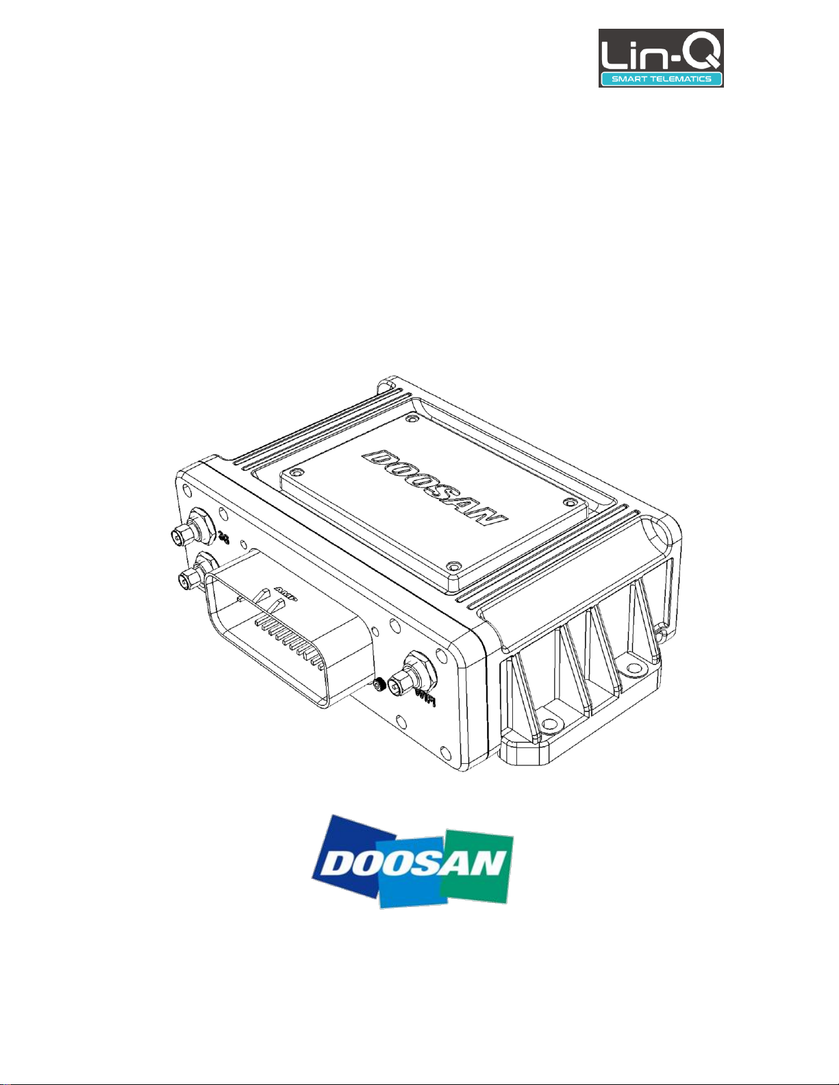
2 Introduction
The DTM-01 is a product to the Doosan Lin-Q system. This product is an IoT(Internet of
Things) terminal that can be used anywhere in the world by using 3G communication
networks or WIFI communication networks.
User can access the Lin-Q system and this product after registrationin on the Lin-Q
homepage or by contacting the administrator.
Below is the Lin-Q system diagram.
Figure 1 Lin-Q System
DTM-01 User’s Guide
Rev.: 1.0
+Update: 26/11/18
Rev. 1.0
Page 7 of 29
This page contains confidential information, which is protected by copyright and is proprietary to DIV
No part of this document may be used, copied, disclosed or conveyed to another party without prior written consent of DIV
3 Overview
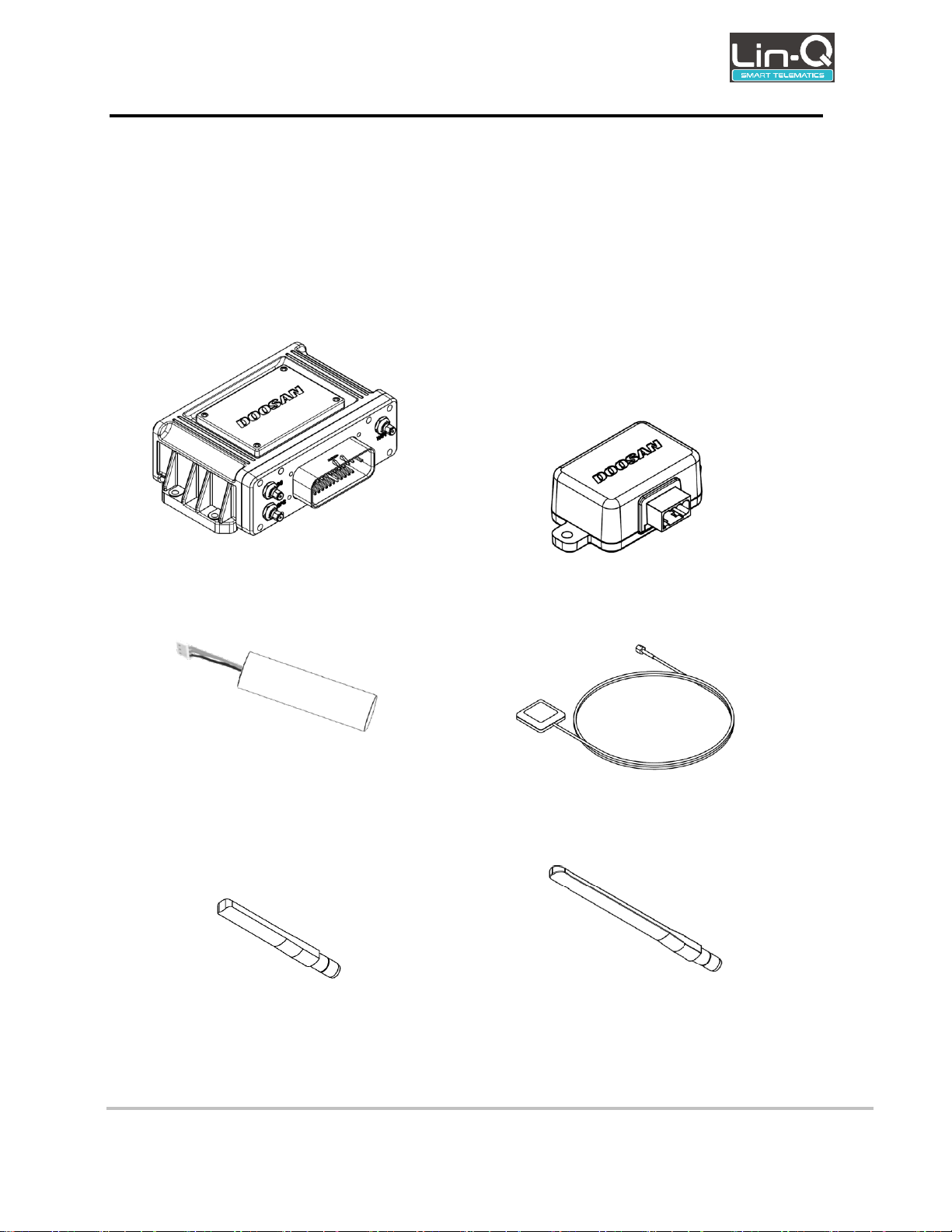
3.1 Components
DTM-01 is composed of the following components. It is required that separate harness cable
assembly for the connection with the vehicle.
DTM-01
Shock Sensor Module
Internal Battery
GPS Antenna
WIFI Antenna
3G Antenna
Figure 2 Package Component
DTM-01 User’s Guide
Rev.: 1.0
+Update: 26/11/18
Rev. 1.0
Page 8 of 29
This page contains confidential information, which is protected by copyright and is proprietary to DIV
No part of this document may be used, copied, disclosed or conveyed to another party without prior written consent of DIV
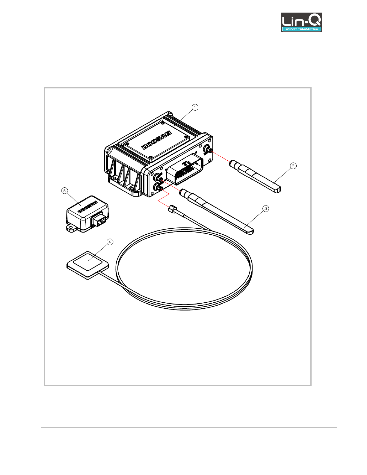
3.2 Connection Diagram
① DTM-01
② WIFI antenna
③ 3G antenna
④ GPS antenna
⑤ Shock sensor module
Figure 3 Connection Diagram
Below figure shows the terminal connection diagram.

DTM-01 User’s Guide
Rev.: 1.0
+Update: 26/11/18
Rev. 1.0
Page 9 of 29
This page contains confidential information, which is protected by copyright and is proprietary to DIV
No part of this document may be used, copied, disclosed or conveyed to another party without prior written consent of DIV
3.3 Features
Dual communication mode
WIFI mode
3G mode
Optimized functions for industrial vehicles
CAN data collection function
Vairous sensor data collection function of vehicle
Periodic transmission function for collected data
Non periodic event data transfer function
Driver limitation function using NFC
Shock detection function
Firmware over the air function.
Remote limitation fuction (will be updated)
Speed limitation / Driver limitation / Torque limitation / RPM limitation
Various I/O ports
4 Digital Input
5 Digital Output
8 Analog Input
CAN
2 UART
 Loading...