

Doosan G70WJD-2A-T3, G145WJD-2A-T3, G25WMI-2A-T2, G185WJD-2A-T3, G240WJD-2B-T3 Installation, Operation & Maintenance Manual
...
OPERATION, MAINTENANCE
MANUAL
G10WMI-2D-T2 (B63)
G25WMI-2A-T2 (B54)
G40WMI-2A-T2 (B50)
G60WJD-2A-T2 (B55)
G70WJD-2A-T3 (D63)
G80
G90WJD-2A-T3 (C24)
G125
G145WJD-2A-T3 (C27)
G185WJD-2A-T3 (C28)
G240WJD-2B-T3 (C31)
G240WCU-2C-T3 (D97)
G290WCU-3B-T3 (C38)
G290WCU-3C-T3 (D77)
G450WCU-2B-T2 (C34)
G450WCU-2C-T2 (D96)
G570WCU-2B-T2 (C37)
G570WCU-2C-T2 (D78)
GENERATOR MODELS
This manual contains important safety information.
Do not destroy this manual.
This manual must be available to the personnel who operate and maintain this machine.
Doosan Infracore Portable Power
1293 Glenway Drive
Statesville, N.C. 28625
www.doosanportablepower.com
Book: 22637300 (8-2-2010) Rev H

2

TABLE OF CONTENTS
Operation & Maintenance Manual
TITLE PAGE
DRAWBAR NOTICE. . . . . . . . . . . . . . . . . . . . . . . . . . . . . . . . . . . . . . . . . . . . . . . . . . . . . 5
SAFETY SYMBOLS . . . . . . . . . . . . . . . . . . . . . . . . . . . . . . . . . . . . . . . . . . . . . . . . . . . . . 7
SAFETY . . . . . . . . . . . . . . . . . . . . . . . . . . . . . . . . . . . . . . . . . . . . . . . . . . . . . . . . . . . . . . 13
HAZARDOUS SUBSTANCE PRECAUTION . . . . . . . . . . . . . . . . . . . . . . . . . . . . . . . . . . . . . . . . . . 20
GENERAL DATA . . . . . . . . . . . . . . . . . . . . . . . . . . . . . . . . . . . . . . . . . . . . . . . . . . . . . . . 21
Unit Model: . . . . . . . . . . . . . . . . . . . . . . . . . . . . . . . . . . . . . . . . . . . . . . . . . . . . . . . . . . . . . . . . . . . . 22
Unit Model: . . . . . . . . . . . . . . . . . . . . . . . . . . . . . . . . . . . . . . . . . . . . . . . . . . . . . . . . . . . . . . . . . . . . 23
Unit Model: . . . . . . . . . . . . . . . . . . . . . . . . . . . . . . . . . . . . . . . . . . . . . . . . . . . . . . . . . . . . . . . . . . . . 24
Consumables Service Parts:. . . . . . . . . . . . . . . . . . . . . . . . . . . . . . . . . . . . . . . . . . . . . . . . . . . . . . . 25
Consumable Service Parts:. . . . . . . . . . . . . . . . . . . . . . . . . . . . . . . . . . . . . . . . . . . . . . . . . . . . . . . . 26
Expendable Service Parts: . . . . . . . . . . . . . . . . . . . . . . . . . . . . . . . . . . . . . . . . . . . . . . . . . . . . . . . . 27
OPERATING INSTRUCTIONS. . . . . . . . . . . . . . . . . . . . . . . . . . . . . . . . . . . . . . . . . . . . . 29
BEFORE TOWING . . . . . . . . . . . . . . . . . . . . . . . . . . . . . . . . . . . . . . . . . . . . . . . . . . . . . . . . . . . . . . 30
TOWING . . . . . . . . . . . . . . . . . . . . . . . . . . . . . . . . . . . . . . . . . . . . . . . . . . . . . . . . . . . . . . . . . . . . . . 31
SETTING UP. . . . . . . . . . . . . . . . . . . . . . . . . . . . . . . . . . . . . . . . . . . . . . . . . . . . . . . . . . . . . . . . . . . 31
DISCONNECT . . . . . . . . . . . . . . . . . . . . . . . . . . . . . . . . . . . . . . . . . . . . . . . . . . . . . . . . . . . . . . . . . 31
BEFORE STARTING . . . . . . . . . . . . . . . . . . . . . . . . . . . . . . . . . . . . . . . . . . . . . . . . . . . . . . . . . . . . 32
STARTING (AUTOSTART MODELS). . . . . . . . . . . . . . . . . . . . . . . . . . . . . . . . . . . . . . . . . . . . . . . . 33
STOPPING (AUTOSTART MODELS) . . . . . . . . . . . . . . . . . . . . . . . . . . . . . . . . . . . . . . . . . . . . . . . 34
REMOTE STARTING AND STOPPING . . . . . . . . . . . . . . . . . . . . . . . . . . . . . . . . . . . . . . . . . . . . . 34
DIAGNOSTICS/AUTO SHUTDOWN (AUTOSTART MODELS). . . . . . . . . . . . . . . . . . . . . . . . . . . . 35
ENGINE CONTROLS and INSTRUMENTS (AUTOSTART MODELS) . . . . . . . . . . . . . . . . . . . . . . 35
CUSTOMER - DIAGNOSTIC GAUGE OPERATION . . . . . . . . . . . . . . . . . . . . . . . . . . . . . . . . . . . . 37
STARTING (KEY START MODELS) . . . . . . . . . . . . . . . . . . . . . . . . . . . . . . . . . . . . . . . . . . . . . . . . 38
STOPPING (KEYSTART MODELS). . . . . . . . . . . . . . . . . . . . . . . . . . . . . . . . . . . . . . . . . . . . . . . . . 40
DIAGNOSTICS and AUTO SHUTDOWN (KEYSTART MODELS). . . . . . . . . . . . . . . . . . . . . . . . . . 40
ENGINE CONTROLS and INSTRUMENTS (Keystart Models) . . . . . . . . . . . . . . . . . . . . . . . . . 41
GENERATOR SYSTEM . . . . . . . . . . . . . . . . . . . . . . . . . . . . . . . . . . . . . . . . . . . . . . . . . . . . . . . . . . 42
MONITOR SWITCHES. . . . . . . . . . . . . . . . . . . . . . . . . . . . . . . . . . . . . . . . . . . . . . . . . . . . . . . . 42
CIRCUIT BREAKERS - Flip to Reset (if equipped) . . . . . . . . . . . . . . . . . . . . . . . . . . . . . . . . . . 43
RECEPTACLES (if equipped) . . . . . . . . . . . . . . . . . . . . . . . . . . . . . . . . . . . . . . . . . . . . . . . . . . 43
PROTECTION/REGULATION . . . . . . . . . . . . . . . . . . . . . . . . . . . . . . . . . . . . . . . . . . . . . . . . . . 43
VOLTAGE SELECTION/ADJUSTMENTS G25 thru G185 . . . . . . . . . . . . . . . . . . . . . . . . . . . . . . . . 44
SWITCH POSITION - 120/208V 3 Phase. . . . . . . . . . . . . . . . . . . . . . . . . . . . . . . . . . . . . . . . . . . . . 45
SWITCH POSITION - 277/480V 3 Phase. . . . . . . . . . . . . . . . . . . . . . . . . . . . . . . . . . . . . . . . . . . . . 45
SWITCH POSITION - 120/240 1Phase . . . . . . . . . . . . . . . . . . . . . . . . . . . . . . . . . . . . . . . . . . . . . . 46
VOLTAGE SELECTION/ADJUSTMENTS G240 thru G570 . . . . . . . . . . . . . . . . . . . . . . . . . . . . . . . 47
120/208V 3 Phase. . . . . . . . . . . . . . . . . . . . . . . . . . . . . . . . . . . . . . . . . . . . . . . . . . . . . . . . . . . . . . . 49
277/480V 3 Phase. . . . . . . . . . . . . . . . . . . . . . . . . . . . . . . . . . . . . . . . . . . . . . . . . . . . . . . . . . . . . . . 49
BASIC DIGITAL CONTROLS OPERATION. . . . . . . . . . . . . . . . . . . . . . . . . . . . . . . . . . . . . . . . . . . 50
3

TABLE OF CONTENTS
Operation & Maintenance Manual
TITLE PAGE
MAINTENANCE . . . . . . . . . . . . . . . . . . . . . . . . . . . . . . . . . . . . . . . . . . . . . . . . . . . . . . . . 65
General . . . . . . . . . . . . . . . . . . . . . . . . . . . . . . . . . . . . . . . . . . . . . . . . . . . . . . . . . . . . . . . . . . . . . . . 66
Scheduled Maintenance . . . . . . . . . . . . . . . . . . . . . . . . . . . . . . . . . . . . . . . . . . . . . . . . . . . . . . . . . . 66
ADJUSTMENT INSTRUCTIONS and TESTING PROCEDURES . . . . . . . . . . . . . . . . . . . . . . . . . . 71
ACCESSING COMPARTMENT . . . . . . . . . . . . . . . . . . . . . . . . . . . . . . . . . . . . . . . . . . . . . . . . . 71
VOLTAGE REGULATOR ADJUSTMENT . . . . . . . . . . . . . . . . . . . . . . . . . . . . . . . . . . . . . . . . . 71
OVERCURRENT RELAY ADJUSTMENT (Set Dial on the OCR Relay) . . . . . . . . . . . . . . . . . . . . . 72
POWER BYPASS SWITCH FOR ENGINE ECU SERVICE. . . . . . . . . . . . . . . . . . . . . . . . . . . . 73
PACKAGE PREVENTIVE MAINTENANCE SCHEDULE. . . . . . . . . . . . . . . . . . . . . . . . . . . . . . 74
ALTERNATOR INSTALLATION AND MAINTENANCE . . . . . . . . . . . . . . . . . . . . . . . . . 75
SAFETY MEASURES. . . . . . . . . . . . . . . . . . . . . . . . . . . . . . . . . . . . . . . . . . . . . . . . . . . . . . . . . . . . 76
INSTALLATION - COMMISSIONING . . . . . . . . . . . . . . . . . . . . . . . . . . . . . . . . . . . . . . . . . . . . . . . . 83
SERVICING-MAINTENANCE. . . . . . . . . . . . . . . . . . . . . . . . . . . . . . . . . . . . . . . . . . . . . . . . . . . . . .88
TECHNICAL CHARACTERISTICS. . . . . . . . . . . . . . . . . . . . . . . . . . . . . . . . . . . . . . . . . . . . . . . . . . 94
4

Drawbar Notice
22637300 5
Operation & Maintenance Manual Drawbar Notice
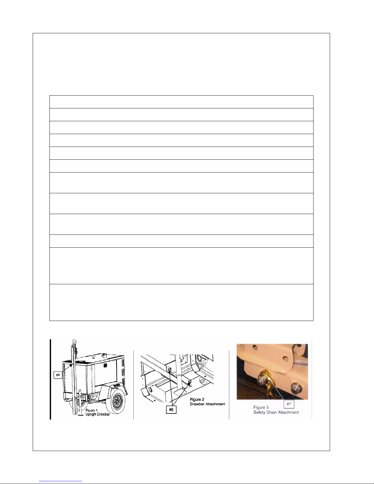
Drawbar Notice
This machine may have been shipped from the factory with the drawbar positioned upright. To
convert from shipping position to towing position, the following tools are required:
Tool Required:
Ratchet, 24mm socket and an 18mm socket to fit ratchet
Torque wrench set to 166 ft-lbs (226 Nm) and 67 ft-lbs. (91 Nm)
24mm socket and an 18mm socket to fit torque wrench
Hardware included: (1) 16mm nut, (2) Washers, (2) Safety Chains
1. Remove hardware box from generator.
2. Open box and remove the bag containing hardware, safety chains and assembly
instructions.
3. Using the jack, raise the front of the unit so that the end of the drawbar is
approximately 1 inch above the ground.
4. While holding the drawbar, carefully remove the temporary retaining bolt that holds
the drawbar to the top of the enclosure (See Fig. 1).
5. Carefully lower drawbar to the Level Position.
6. Install the bolt (that was removed in Step 4) with the washers and nut from the
included hardware to secure the end of the drawbar underneath the unit and torque to
166 ft-lbs (226 Nm). Also torque the drawbar pivot bolt to 166 ft-lbs. (226 Nm). See
Figure 2).
7. Install safety chains by first removing the longest bolt used to attach the hitch then
insert the last link of one chain onto the bolt. Slide one spa cer back on the bo lt and pu t
the assembly back into the hitch. Slide the other spacer onto th e bolt, th en the last link
of the other safety chain washer. Tighten the nut to 67 ft-lbs (91 Nm).
6 22637300

Safety Symbols
22637300 7
Operation & Maintenance Manual Safety Symbols
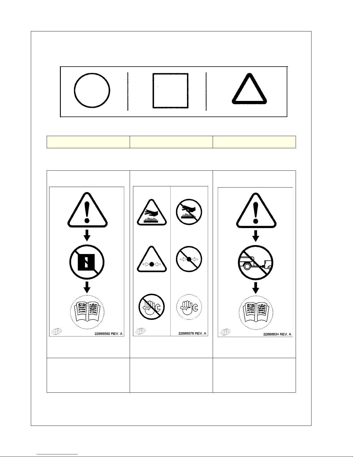
Symbols below point out potential safety hazards and provide important information about this
machine. Read and understand. Heed warnings and follow instructions. If you do not
understand, inform your supervisor.
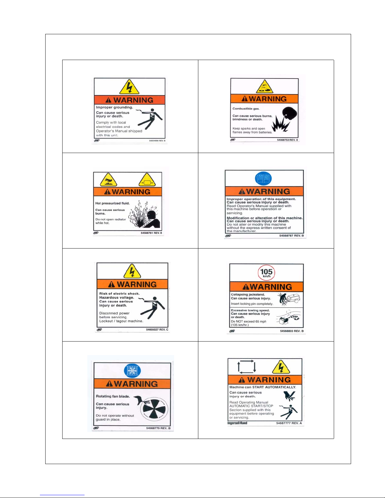
Prohibition/ Mandatory Information/Instructions WARNING
WARNING - Read the
operator’s manual before
operating this machine.
WARNING - Do not open
radiator until radiator is
cool and pressure is
WARNING - Read the
operator’s manual before
towing machine.
relieved.
8 22637300
Safety Symbols Operation & Maintenance Manual
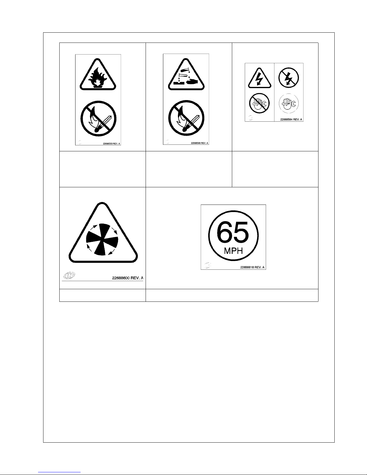
WARNING - Diesel fuel is
flammable. No open
flames or sparks.
WARNING - Battery
contains acid. Gases are
flammable. No open
flames or sparks.
WARNING - Do not
perform maintenance until
all electrical power has
been disconnected.
WARNING - Rotating fan. 65 MPH maximum towing speed.
22637300 9
Operation & Maintenance Manual Safety Symbols
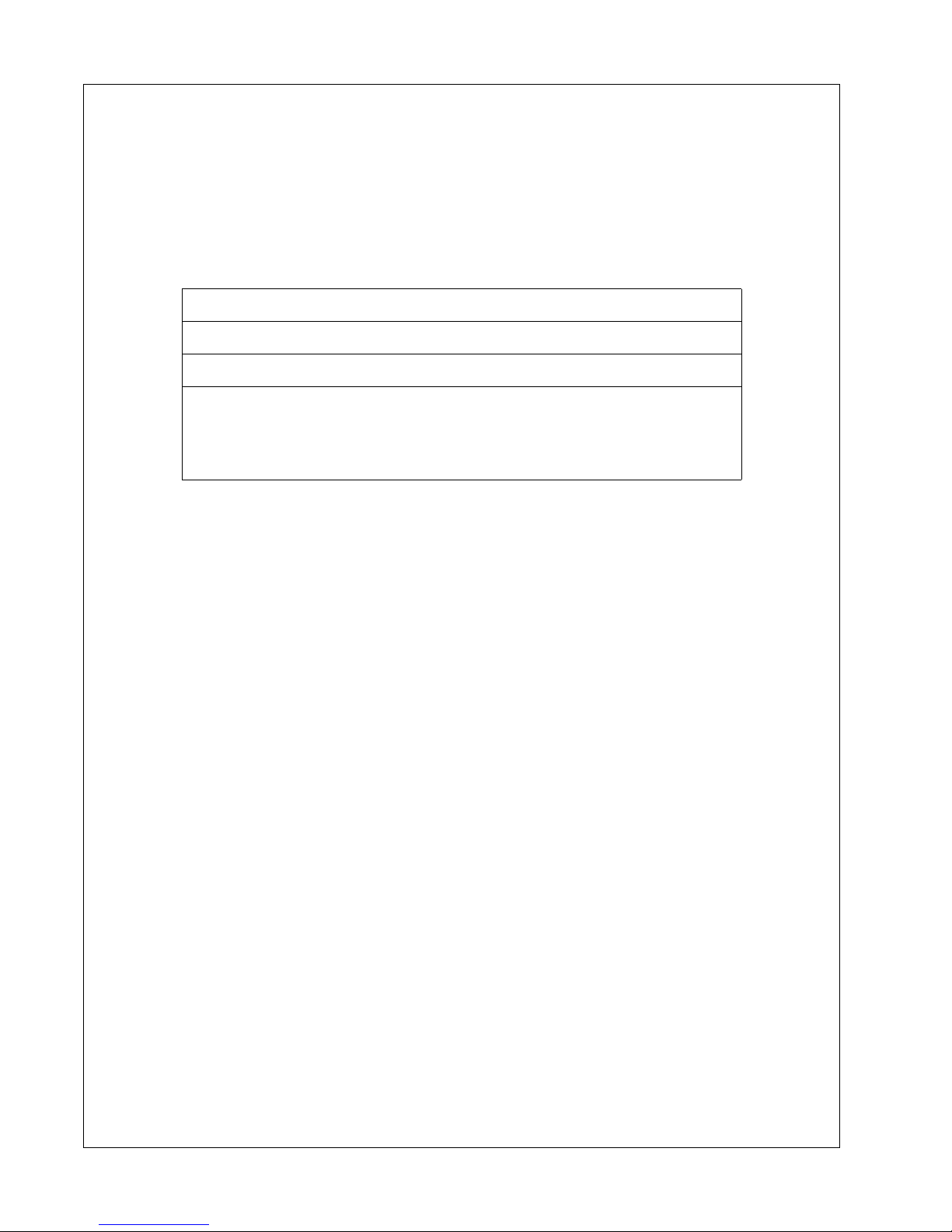
Safety Symbols
Look for these signs on machines manufactured in North America, which point out
potential hazards to the safety of you and others. Read and understand thoroughly.
Heed warnings and follow instructions. If you do not understand, inform your
supervisor.
Safety Decals area available free of charge.
Safety decals are identified by the decal heading:
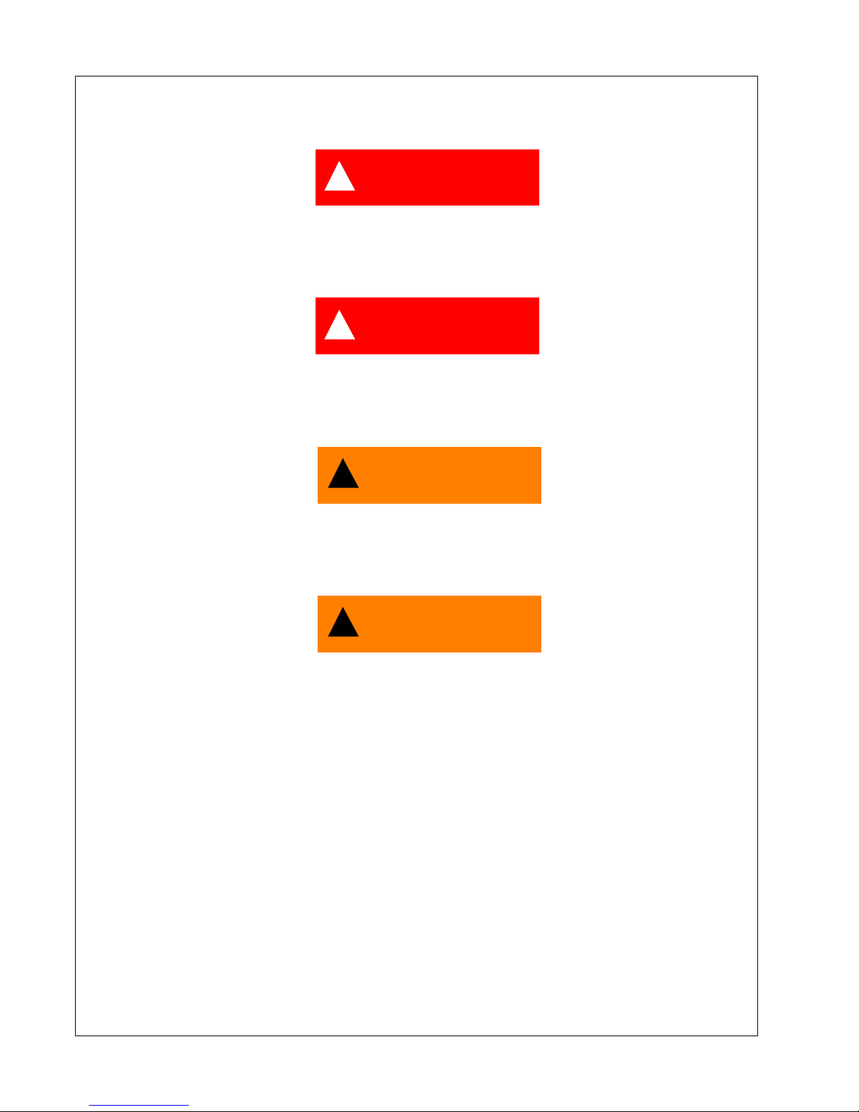
DANGER, WARNING or CAUTION
Decal part numbers are on the bottom of each decal and are listed
in the parts manual. Help promote product safety! Assure that
decals are present on the machines. Replace decals that are not
legible.
10 22637300
Safety Symbols Operation & Maintenance Manual
22637300 11

Always use genuine replacement parts!
12 22637300

Safety
22637300 13
Operation & Maintenance Manual Safety
Safety
!
DANGER
This machine is not designed for operating life-sustaining equipment. It
is equipped with a safety shutdown system that will cause the machine to
stop operating whenever a shutdown condition is present.
!
DANGER
Never operate the engine of this machine inside a building without
adequate ventilation. Avoid breathing exhaust fumes when working on
on near the machine.
!
WARNING
A battery contains sulfuric acid and can give off gases which are
corrosive and potentially explosive. Avoid contact with skin, eyes, and
clothing. In case of contact, flush area immediately with water.
!
WARNING
Improper operation of this equipment can cause severe injury or death.
Read Operator’s Manual supplied with this machine before operation or
service.
Modification or alteration of this machine CAN result in severe injury or
death. Do not alter or modify this machine without the express written
consent of the manufacturer.
14 22637300
Safety Operation & Maintenance Manual
!
CAUTION
Exercise extreme caution when using booster battery. To jump battery,
connect ends of one booster cable to the positive (+) terminal of each
battery. Connect one end of other cable to the negative (-) terminal of the
bosster battery and other end to a ground connection away from dead
battery (to avoid a spark occurring near any explosive gases that may be
present). After starting unit, always disconnect cables in reverse order.
!
WARNING
Never inspect or service unit without first disconnecting battery cable(s)
to prevent accidental starting.
Wear eye protection while cleaning unit with compressed air, to prevent
debris from injuring eyes.
!
WARNING
HOT PRESSURIZED FLUID - Remove cap slowly to relieve PRESSURE
from HOT radiator. Protect skin and eyes. HOT water or steam and
chemical additives can cause serious personal injury.
22637300 15
Operation & Maintenance Manual Safety
!
WARNING
Flammable Fuels - Do not fill tank when engine is running.
Do not smoke or use an open flame in the vicinity of the generator set or
fuel tank.
Do not permit smoking, open flame, or sparks to occur near the battery,
fuel, cleaning solvents or other flammable substances and explosive
gases.
Do not operate Genset if fuel has been spilled inside or near the unit.
!
WARNING
Electrical Shock -
Do not operate electrical equipment while standing in water, on wet
ground or with wet hands or shoes.
Use extreme caution when working on electrical components. Battery
voltage (12V/24V DC) is present unless the battery cables have been
disconnected. Higher voltage (potentially 480V) is possibly present at all
times.
Always treat electrical circuits as if they were energized.
Disable Start Control before attempting any repair service, disconnect all
leads to electrical power requirements and disconnect battery to prevent
start up.
GROUNDING
!
WARNING
Depending upon your application, it may be MANDATORY to ground this unit to earth or to
NOT ground this unit to earth. Comply with local electrical codes and Operation Manual.
16 22637300

Safety Operation & Maintenance Manual
!
WARNING
The Generator Set can produce high voltages, which can cause severe
injury or death to personnel and damage to equipment. The Generator Set
should have proper internal and external ground when required by the
National Electric Code.
The Generator Set is internally grounded neutral to the frame of the
Generator Set. This internal ground connection is essential for proper
Generator Set performance and personal protection.
External grounding consists of connecting the generator neutral to a
solid earth ground, and is the responsibility of the operator, when
grounding is required by National Electrical Code, Article 250, and other
local codes as applicable. Several methods are employed to externally
ground portable generator sets, depending on the intended use and code
requirements. In all cases, a continuous length of splice-free copper
cable, no smaller than AWG#8, shall be used for the external ground
conductor, when grounding is required.
A qualified, licensed electrical contractor, knowledgeable in local codes,
should be consulted.
The Generator Set has two main applications:
(1) If the Generator Set is supplying electrical power to portable equipment, the vehicle frame
shall NOT be grounded to earth per National Electrical Code, Article 250-34(b). All other
provisions of the Article shall be complied with.
(2) If the Generator Set is connected to a temporary or fixed distribution system (such as a
building), grounding of the vehicle frame is required at the service entrance to the building, per
National Electrical Code, Article 250-20 (b).
If the Generator Set is supplying power to more than one temporary or fixed wiring system, a
separate ground cable must be connected from the generator neutral to each distribution
systems ground as detailed above.
!
WARNING
Failure to properly ground the Generator Set can result in severe injury
or death.
IF USED AS ALTERNATE POWER SUPPLY
Connect only after the main service entrance switch has been DISCONNECTED and
LOCKED OPEN. In addition, circuit overload protection must be provided in accord ance with
National Electrical Codes and local regulations.
22637300 17
Operation & Maintenance Manual Safety
!
WARNING
TOWING -
Do not tow this unit in excess of 65 mph (104 km/hr).
Do not tow this unit with a vehicle whose towing capacity is less than the
gross vehicle weight.
Steps for determining correct load limit -
1. Locate the statement “The weight of cargo should never exceed
xxx kg or xxx lbs” on your vehicle’s placard.
2. This figure equals the available amount of cargo and luggage l oad
capacity.
3. Determine the combined weight of luggage and cargo being loaded
on the vehicle. That weight may not safely exceed the available cargo
and luggage load capacity.
Always make sure the wheels, tires and towbar connectors are in safe
operating condition and tow bar is properly connected before towing.
Chock the wheels of the unit when it is not connected to the tow vehicle.
Do not store or transport material or equipment in or on the unit.
!
WARNING
Drawbar/Hitch Hookup -
Safety chains must be crossed under drawbar and attached to towing
vehicle to prevent drawbar from dropping to ground in event of coupling
failure.
18 22637300
Safety Operation & Maintenance Manual
!
WARNING
If the drawbar is removed from this machine, use new OEM fasteners,
thread locking compound and torque per the tables included in this
manual, when re-installing the drawbar.
!
WARNING
Voltage Selection - Do not turn Voltage Selector Switch while engine is
running. Voltage selection, adjustment and electrical connections shall
be performed only by qualified personnel.
!
CAUTION
Welding -
Prior to any welding, disconnect alternator relays, diagnostic circuit
board, voltage regulator circuit board, meters, circuit breakers and
battery cables. Open all circuit breakers, and remove any external
connections (except grounding rod). Connect the welding ground as
close as possible to the area being welded.
!
WARNING
Electrical Loading -
Never make electrical connections with the unit running.
Before placing the unit in operation, verify the electrical rating of the
Generator Set and do not exceed generator set ratings.
22637300 19

Operation & Maintenance Manual Safety
!
CAUTION
Use extreme care to avoid contacting hot surfaces (engine exhaust
manifold and piping).
HAZARDOUS SUBSTANCE PRECAUTION
Ensure that adequate ventilation of the cooling system and exhaust gases is maintained at all
times.
The following substances are used in the manufacture of this machine and may be hazardous
to health if used incorrectly.
Avoid ingestion, skin contact and breathing fumes for the following substances: Antifreeze,
Engine Lubricating Oil, Preservative Grease, Rust Preventative, Diesel Fuel and Battery
Electrolyte.
The following substances may be produced during the operation of this machine and may be
hazardous to health:
• Avoid build-up of engine exhaust fumes in confined spaces.
• Avoid breathing exhaust fumes.
• Avoid breathing brake lining dust during maintenance.
• Always operate in a well ventilated area.
20 22637300

General Data
22637300 21

Operation & Maintenance Manual General Data
General Data
Unit Model:
UNIT MODEL G10A G25B, G25C G40B, G40C G60
Engine Speed - RPM 1800 1800 1800 1800
ENGINE Diesel Diesel Diesel Diesel
Manufacturer IR IR IR JD
Model 3IRL2N 4IRQ2N 4IRS2N 5030TF270
FLUID CAPACITIES
Engine Crankcase Lubricant .98 1.7 gal 2.64 gal 2.96 gal
Fuel Tank 21 36 gal 47 gal 103 gal
Radiator & Engine Coolant 2.0 4 gal 5 gal 6 gal
Electrical System 12VDC 12VDC 12VDC 12VDC
RUNNING GEAR
Tire Size ST175/80D13 ST205/75D15 ST205/75D15 ST205/75D15
Inflation Pressure (Cold) 50 psi 50 psi 50 psi 50 psi
Towing Speed (Maximum) 65 mph 65 mph 65 mph 65 mph
UNIT MEASUREMENTS/ WEIGHTS (w/running gear)
Overall length (inches) 121 131 143 156
Overall width (inches) 56 60 66 69
Overall height (inches) 43 67 72 85
Track width (inches) 48 50 56 60
Weight (with fuel) 1708 lbs 2588 lbs 3508 lbs 4658 lbs
Weight (less fuel) 1529 lbs 2420 lbs 3078 lbs 3895 lbs
22 22637300

General Data Operation & Maintenance Manual
Unit Model:
UNIT MODEL G70A G80A G90A G125 G145B G185
Engine Speed - RPM 1800 1800 1800 1800 1800 1800
ENGINE Diesel Diesel Diesel Diesel Diesel Diesel
Manufacturer JD JD JD JD JD JD
Model 4045
TF285E
FLUID CAPACITIES
Engine Crankcase Lubricant 3.57 gal 3.57 gal 3.57 gal 3.57 gal 3.57 gal 8.59 gal
Fuel Tank 103 gal 103 gal 190 gal 145 gal 190 gal 255.3 gal
Engine Coolant Only 6 gal 6 gal 3.1 gal 5.3 gal 3.1 gal 3.1 gal
Electrical System 12VDC 12VDC 12VDC 12VDC 12VDC 12VDC
RUNNING GEAR
Tire Size ST205/
75D15
Inflation Pressure (Cold) 50 PSI 50 PSI 50 PSI 50 psi 50 psi 50 psi
Towing Speed (Maximum) 65 mph 65 mph 65 mph 65 mph 65 mph 65 mph
UNIT MEASUREMENTS/ WEIGHTS (w/running gear)
Overall length (inches) 156 156 165 166 166 204
Overall width (inches) 69 69 71 72 72 76
Overall height (inches) 85 85 84 80 84 95
Track width (inches) 60 60 63 64 63 61.7
4045
TF275
ST205/
75D15
4045
HF285
ST205/
75D15
6068
TF275-123
ST205
75D15
4045
HF485
ST205
75D15
6068
HF285
9.50-16.5
LT/E
Weight (with fuel) 5105 lbs 5174 lbs 6466 lbs 5632 lbs 7220 lbs 9166 lbs
Weight (less fuel) 4435 lbs 4478 lbs 5004 lbs 4518 lbs 5758 lbs 7205 lbs
22637300 23

Operation & Maintenance Manual General Data
Unit Model:
UNIT MODEL G240 G290 G450 G570
Engine Speed - RPM 1800 1800 1800 1800
ENGINE Diesel Diesel
Manufacturer JD Cummins Cummins Cummins
Model 6068HF485 QSL9G3 QSX15 QSX15
FLUID CAPACITIES
Engine Crankcase Lubricant
(gal)
Fuel Tank (gal) 255.3 gal 389.5 gal 652 652
Engine Coolant Only (gal) 3.1 gal 2.91 gal 15 15
Electrical System VDC 12VDC 24VDC 24VDC 24VDC
RUNNING GEAR
Tire Size 9.50-16.5 LT/E 9.50-16.5 LT/E 9.50 -16.5 LT/E 9.50 -16.5 LT/E
Inflation Pressure (Cold) psi 50 PSI 50 PSI 75 75
Towing Speed (Maximum) 65 mph 65 mph 65 mph 65 mph
UNIT MEASUREMENTS/ WEIGHTS
Overall length (in/mm) 204 221 261/6626 261/6626
Overall width (in/mm) 76 78 86/2181 86/2181
Overall height (in/mm) 95 111 120/3042 120/3042
Track width (in/mm) 65 68.5 74/ 74/
Weight (with fuel) lbs 9678 lbs 11,957 lbs 18271 18573
Weight (less fuel) lbs 7717 lbs 8989 lbs 13868 14170
8.59 gal 7 gal 24 24
24 22637300

General Data Operation & Maintenance Manual
Consumables Service Parts:
For Models: G10A G25B G40B G60 G 70A G80A G125
Air Cleaner Element
(Engine) primary
Air Cleaner Element
(Engine) secondary optional
Engine Oil Filter
Element
Fuel Water Separator
Element
Engine Fuel Element 85426815 85426823 22712475 22556138 22969257 22206197 22206197
Inline Fuel Filter NA NA NA NA NA NA NA
MAINTENANCE KITS
250 hour Maintenance
Kit (without fluids)
250 hour Maintenance
Kit (& engine fluids)
500 hour Maintenance
Kit (without fluids)
500 hour Maintenance
Kit (& Engine fluids
fluids)
36890135 35393685 35393685 54471834 54471834 54471834 54717145
NA NA NA NA 54471842 NA 54717152
85426849 85426856 22712467 22545867 22206148 22206148 22206148
54525530 54525530 54525530 54525530 22969265 54525530 54468178
44003929 44003945 44000404 44003960 44029098 44003986 44003986
44003648 44003663 44000388 44003705 44029072 44003721 44003747
44003937 44003952 44000412 44003978 44029106 44003994 44004000
44003655 44003671 44000396 44003713 44029080 44003739 44003754
Protec Eng Fluid - 5 gal 54480918 54480918 54480918 54480918 54480918 54480918 54480918
Protec Eng Fluid -1 gal 36875938 36875938 36875938 36875938 36875938 36875938 36875938
22637300 25

Operation & Maintenance Manual General Data
Consumable Service Parts:
For Models: G450 G570
Air Cleaner Element
(Engine) primary
Air Cleaner Element
(Engine) secondary optional
Engine Oil Filter
Element
Fuel Water Separator
Element
Engine Fuel Element 54662036 54662036
MAINTENANCE KITS
250 hour Maintenance
Kit (without fluids)
250 hour Maintenance
Kit (& engine fluids)
500 hour Maintenance
Kit (without fluids)
500 hour Maintenance
Kit (& Engine fluids
fluids)
36864361 36864361
36864379 36864379
54662028 54662028
22201396 22201396
44020279 44020295
44020212 44020238
44020287 44020303
44020220 44020246
Protec Eng Fluid - 5 gal 54480918 54480918
Protec Eng Fluid -1 gal 36875938 36875938
26 22637300

General Data Operation & Maintenance Manual
Expendable Service Parts:
For Models: G90A G145B G185 G240 G290
Air Cleaner Element
(Engine) primary
Air Cleaner Element
(Engine) secondary optional
Engine Oil Filter
Element
Fuel Water Separator
Element
Engine Fuel Element 22206197 22 969257 22969257 22969257 22765325
MAINTENANCE KITS
250 hour Maintenance
Kit (without fluids)
250 hour Maintenance
Kit (& engine fluids)
500 hour Maintenance
Kit (without fluids)
500 hour Maintenance
Kit (& Engine fluids
fluids)
54471834 54717145 54717145 22119168 89288971
NA 54717152 54717152 22119176 89288989
22206148 22206148 22206148 22206148 22177737
54525530 22969265 22969265 22969265 22637904
TBD 44016038 44016038 44016038 44020253
TBD 44016004 44016004 44016004 44020196
TBD 44016046 44016046 44016020 44020261
TBD 44016012 44016012 44016053 44020204
Protec Eng Fluid - 5 gal TBD 54480918 54480918 54480918 54480918
Protec Eng Fluid -1 gal TBD 36875938 36875938 36875938 36875938
22637300 27

28 22637300

Operating Instructions
22637300 29
Operation & Maintenance Manual Operating Instructions
Operating Instructions
Never operate unit without first observing all safety warnings and carefully reading the
operation and maintenance manual shipped from the factory with this machine.
BEFORE TOWING
!
WARNING
Failure to follow these instructions can cause severe injury or death.
!
CAUTION
- Position the tow vehicle to align its hitch with the pintle eye or coupler.
- Engage the parking brake and chock the wheels of the tow vehicle.
- Stand to the side and ensure pin is FULLY inserted (secure) in tube of
jack.
- Crank jack to lower pintle eye coupler onto the hitch and to raise foot off
the ground. Pull pin from tube of jack. Fold jack handle down and forward.
Swing up jack tube and FULLY insert pin in tube.
- Connect machine towing lights to tow vehicle.
- Remove chocks from tow vehicle wheels.
Steps for determining correct load limit -
1. Locate the statement “The weight of cargo should never exceed xxx kg or xxx lbs” on
your vehicle’s placard.
2. This figure equals the available amount of cargo and luggage load capacity.
3. Determine the combined weight of luggage and cargo being loaded on the vehicle.
That weight may not safely exceed the available cargo and luggage load capacity.
30 22637300
 Loading...