

Page 1

1Electrical System
Page 2

Page 3

SP001038
ELECTRICAL SYSTEMSP001038
Electrical
System
Edition 1
Electrical System
SP001038
Page 1
Page 4

MEMO
Electrical System
Page 2
SP001038
Page 5

SP001038
Page 3
Electrical System
Table of Contents
Electrical System
Safety Precautions ............................................... 7
Applicable Models ................................................ 7
Introduction........................................................... 9
Electrical Supply System .................................... 10
Engine Starting Circuit........................................ 12
Start Operation .............................................................. 12
After Start ...................................................................... 14
Engine Preheating System ................................. 16
Engine Stop ........................................................ 18
Charging System ................................................ 20
Monitoring System.............................................. 21
Instrument Panel ........................................................... 22
Monitoring System Schematic....................................... 24
Operation............................................................ 26
Instruments.................................................................... 26
Warning and Indicator Lights.............................. 28
Indication of Warning Lights .......................................... 28
Indication of Multifunction Gauge and
Letter Information Area.................................................. 29
Initial Operation .................................................. 31
Mode Selector Switch......................................... 31
Graphic Information Area Display....................... 32
Overview ....................................................................... 32
Main Menus for the Graphic Display Area..................... 33
Menu Selector Buttons .................................................. 33
Main Menu.......................................................... 34
Language ...................................................................... 34
Set Clock ....................................................................... 35
Filter/Oil Info .................................................................. 35
Adjust Display................................................................ 36
Page 6

SP001038
Electrical System
Page 4
Set Password ................................................................ 37
Special Menu...................................................... 38
Entering/Accessing and Exiting/Escaping Menus ......... 38
Special Menu Selections ............................................... 39
Electronic Hydraulic Control System (e-EPOS).. 56
Control System Schematic ............................................ 56
Power Mode Control........................................... 58
Operation ....................................................................... 60
Power Mode Control - Circuit Diagram............... 62
Work Mode Control............................................. 64
Operation ....................................................................... 65
Work Mode Control - Circuit Diagram................. 66
Engine Control System....................................... 67
Engine Control Dial............................................. 68
Engine Control Circuit Diagram .......................... 69
Automatic Deceleration Control
(Auto Idle Control) .............................................. 70
Engine Overheat Protection System .................. 72
Power Boost Mode ............................................. 74
Operation ....................................................................... 74
Power Boost Control - Circuit Diagram ......................... 76
Automatic Travel Speed Control......................... 78
Automatic Travel Speed Control - Circuit Diagram ....... 80
Self-diagnostic Function .....................................81
e-EPOS Controller......................................................... 81
Air Conditioner System....................................... 83
Outline ........................................................................... 83
Internal and External Filters .......................................... 84
Air-Conditioning System Layout .................................... 86
Air Conditioner/heater Circuit Diagram.......................... 87
Air Conditioner/heater Unit ............................................ 88
Ambient Air Temperature Sensor .................................. 93
Page 7

SP001038
Page 5
Electrical System
Sun Sensor.................................................................... 94
Control Panel................................................................. 94
Compressor ................................................................. 102
Receiver Dryer ............................................................ 102
Troubleshooting................................................ 103
Weight of R134a Gas Used In Machines ......... 105
Refrigerant System Repairs ............................. 106
Refrigerant Safe Handling Procedures........................ 106
Repair and Replacement Procedure ........................... 107
Refrigerant Recovery .................................................. 109
Vacuuming Refrigerant System................................... 109
Leakage Check ........................................................... 111
Refrigerant Charging ................................................... 111
Inspecting System For Leakage .................................. 113
Wiper System ................................................... 114
Wiper Circuit................................................................ 114
Wiper operation ........................................................... 115
Lighting System ................................................ 118
Lighting System Circuit Diagram ................................. 118
Kind of Light ................................................................ 119
Operation ..................................................................... 119
Audio Controller................................................ 120
Audio Controller Circuit Diagram................................. 120
Page 8

MEMO
Electrical System
Page 6
SP001038
Page 9
SP001038
Page 7
Electrical System
SAFETY PRECAUTIONS
APPLICABLE MODELS
The contents of this section apply to the following models and
serial number ranges.
CAUTION!
Follow all safety recommendations and safe shop practices
outlined in the front of this manual or those contained
within this section.
Always use tools and equipment that are in good working
order.
Use lifting and hoisting equipment capable of safely
handling load.
Remember, that ultimately safety is your own personal
responsibility.
MODEL SERIAL NUMBER RANGE
DX140LC 5001 and Up
DX180LC 5001 and Up
Page 10

Page 8
SP001038Electrical System
Page 11

SP001038
Page 9
Electrical System
INTRODUCTION
The electrical system for this equipment is DC 24 volts. The
rated voltage for all electric components is 24 volts with the
exception of the stereo and the air-conditioning control actuator.
The system contains two 12 volt batteries connected in series
and a three phase AC generator with a rectifier. The electric
wiring used in the system is easily identifiable by the insulator
color. The color symbols used in the electrical system are listed
in the following chart.
Electric Wire Color
NOTE: RW: Red wire with White stripe
R - Base Color, W - Stripe Color
NOTE: 0.85G: Nominal sectional area of wire core less
insulator = 0.85 mm
2
Symbol Color
W White
G Green
Or Orange
B Black
L Blue
Lg Light green
R Red
Gr Gray
P Pink
Y Yellow
Br Brown
V Violet
Page 12

SP001038Electrical System
Page 10
ELECTRICAL SUPPLY SYSTEM
The electric power circuit supplies electric current to each
electric component. It consists of a battery, battery relay, starter
switch, circuit breaker, fusible link and fuse box.
The negative terminal of the battery is grounded to the vehicle
body.
Even when the starter switch (5) is in the "OFF" position, electric
current is supplied to the following components through battery
(1) o fusible link (3) o fuse box (6).
1. Terminal "1" of DC-DC converter (for memory backup of
stereo)
2. Terminal "B" of starter switch
3. Hour meter
4. Engine controller
5. Fuel feeder pump switch
6. Terminal "6" of wiper motor
7. Terminal "13" of wiper controller
8. Terminal "CN6-11" of instrument panel
9. Terminal "CN9-6" of air conditioner panel
10. Cabin light
When the starter switch (5) is in the "ON or START" positions,
the current flows from the battery (1) o fusible link (3) o fuse
box (6) o "B" terminal of starter switch (5) o "BR" terminal of
starter switch (5) o "BR" terminal of battery relay (2) which
activates the coil of the battery relay and the electric supply
system is energized.
When the battery relay's contacts are connected, all electric
devices can be operated.
While the engine is not running, the electric power for all electric
devices are supplied by the battery. Once the engine is started
the power is supplied from the alternator (7).
Page 13

SP001038
Page 11
Electrical System
TRIO DIODE
0.5 uF
8
START
ON
OFF
STARTER SWITCH CONNECTION
TML
PST
B BR R1 R2 C ACC
F+
F-
E
REG.
I(L)
FIELD
GRD
7
12V 100AH
R(I)
P(R)
B+
8
B(B+)
-
E
BR
4
B
12V 100AH
1
+ - +
2
A
6
R2
ACC
R1
B
BR
C
5
0.5G
3
FG007233
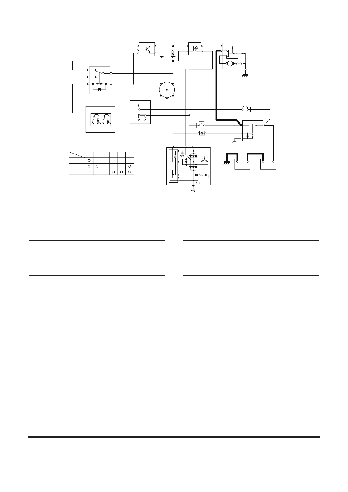
Figure 1 ELECTRIC POWER CIRCUIT DIAGRAM
Reference
Number
Description
1 Battery
2 Battery Relay
3 Fusible Link
4 Circuit Breaker
5 Starter Switch
6 Fuse Box
7 Alternator
8 Diode
Reference
Number
Description
Page 14

SP001038Electrical System
Page 12
ENGINE STARTING CIRCUIT
Start Operation
When the starter switch is turned to the "START" position, the
"S" and "E" terminals of the starter controller (7) are connected.
At this time the contacts in the starter relay (8) are closed by the
current flow from the battery (1) o fusible link (3) ofuse box (6)
o "B" terminal of starter switch (5) o "C" terminal of starter
switch (5) o "30" terminal of starter relay (12) - "87a" terminal o
"C" terminal of starter relay (8) - "D" terminal o "S" terminal of
starter controller (7) - "E" terminal o ground.
When the contact point "B" and "PP" of starter relay (8) are
connected, the pinion gear of the starter (9) is pushed forward
and makes contact with the ring gear of the flywheel and the
internal contacts of the starter are connected. The current flows
from the battery (1) o "A" terminal of the battery relay (2) o "B"
terminal of the battery relay (2, Figure 3) o "B" terminal of the
starter (9). The starter motor is rotated and the engine is started.
If the instrument panel has the password function activated ,
input number should match the set number, otherwise the start
circuit closes and the engine does not start.
NOTE: If the security system is "LOCKED," a four-digit
password will be required to start the engine. If the
system is "UNLOCKED," no password will be
required and this display screen will not appear.
In the event the security system is locked, current
flows from battery (1)
o
fusible link (3) ofuse box
(6)
o
"B" terminal of starter switch (5) o "ACC"
terminal of starter switch (5)
o
"86" terminal of starter
relay (12)
o
"85" terminal of starter relay (12)
o
"CN1-15" terminal of e-EPOS (13) o ground. This
current flow causes the coil in starter relay (12) to be
activated, opening contacts at "87a" terminal. This
prevents starter relay (8) from functioning.
C
H
C
E
F
H
02/05 [MO] 11:30
E/G SPEED
0
RPM
FG001445
ENTER
PASSWORD
Figure 2
Page 15
SP001038
Page 13
Electrical System
TRIO DIODE
0.5 uF
CN1-15
TML
STARTER SWITCH CONNECTION
ON
START
OFF
PST
F-
E
GRD
R2BRB R1 ACCC
13
CN2-1
6
P(R)
R(I)
B(B+)
REG.
I(L)
F+
FIELD
B+
11
4
12
85 86
30
87a
87
P
N
B
C
BR
R2
R1
ACC
B
5
E
S
11
D
C B
PP
7 8
2
-10+ -
1
BR
E
B
A
+
3
A
B
C
9
FG007234
Figure 3 STARTER CIRCUIT (1) - WHILE STARTING
Reference
Number
Description
1 Battery
2 Battery Relay
3 Fusible Link
4 Circuit Breaker
5 Starter Switch
6 Fuse Box
7 Starter Controller
8 Starter Relay
9 Starter
10 Alternator
11 Diode
12 Starter Relay 2
13 e-EPOS Controller
Reference
Number
Description
Page 16

SP001038Electrical System
Page 14
After Start
Once the engine has been started, the belt driven alternator (10)
generates a current.
The output generated by the alternator (10) is a square wave
pulse voltage through the "P" terminal and the frequency of the
pulse voltage is proportional to the rotation of the alternator.
The starter controller (7) monitors the frequency of the output
current. Once the frequency is equivalent to 500 rpm, it is
sensed and the connection between "S" and "E" terminals and
the connection between "B" and "PP" terminals are opened. As
a result the rotation of the starter (9) is stopped. Once the engine
is running, the starter (9) will not operate even if the starter
switch (5) is moved to the start position, preventing possible
damage to the starter.
Page 17

SP001038
Page 15
Electrical System
Operation of the Start Circuit (2) - Immediately After Start
FG007237
TRIO DIODE
0.5 uF
ACC
85 86
STARTER SWITCH CONNECTION
ON
START
TML
OFF
PST
BRB
CN1-15
ACCR2R1 C
R2
CN2-1
R1
B
C
BR
87
87a
P
30
B
E
N
S
C B
D PP
+- + -
E
B
BR
A
B
A
C
12
13
10
6
11
4
5
7
11
8
1
2
3
9
F-
E
GRD
P(R)
R(I)
I(L)
REG.
F+
B+
B(B+)
FIELD
igure 4 OPERATION OF START CIRCUIT (2) - IMMEDIATELY AFTER START
Reference
Number
Description
1 Battery
2 Battery Relay
3 Fusible Link
4 Circuit Breaker
5 Starter Switch
6 Fuse Box
7 Starter Controller
8 Starter Relay
9 Starter
10 Alternator
11 Diode
12 Starter Relay 2
13 e-EPOS Controller
Reference
Number
Description
Page 18

SP001038Electrical System
Page 16
ENGINE PREHEATING SYSTEM
An air heater (8) is installed in the intake manifold of the engine.
When the starter switch (5) is turned "ON," the current flows
from the battery (1) o fusible link (3) o fuse box (6) o "B"
terminal of starter switch (5) o "BR" terminalof starter switch (5)
o "1-39" terminal of engine controller (12), causing current to
flow though "1-16" terminal of engine controller (12) o "C and
D" terminals of preheat relay (7) o "1-04" terminals of engine
controller (12) o ground.
This current flow causes the coil in preheat relay (7) to be
activated, closing contacts.
When the contacts of the preheat relay (7) are closed, the
heating coils of the air heating device (8) are heated by current
flowing from the battery (1) o battery relay (2) o preheat relay
(7) o air heater (8) o ground.
The duration of the heating cycle depends on the temperature of
engine coolant. The preheat indicator light in the instrument
panel (9) will turn "ON" during preheating cycle.
The preheat relay (7) is controlled by the engine controller (12)
and operates only at temperatures of 10°C (50°F) and below.
The longer the preheating period, the lower the temperature of
coolant is.
Page 19

SP001038
Page 17
Electrical System
(1)
12
1-07
1-13
D
+
H
ON
OFF
START
11
1-40
1-34,35
7
C
PREHEAT
L5
CN4-4,5,6
CN2-1
CN7-4,5,6
CN6-1,2
9
6
2
STARTER SWITCH CONNECTION
-
200A
B
TML
PST
B BR R1
-
1
+
R1
R2
ACC
B
C
BR
5
E
10
BR
B
ACCR2 C
- +
A
4
3
FG007137
Figure 5 ENGINE PREHEAT CIRCUIT
Reference
Number
Description
1 Battery
2 Battery Relay
3 Fusible Link
4 Circuit Breaker
5 Starter Switch
6 Fuse Box
7 Preheat Relay
8 Air Heater
9 Preheat Indicator Light
10 Diode
11 e-EPOS Controller
12 Engine Controller
Reference
Number
Description
Page 20

SP001038Electrical System
Page 18
ENGINE STOP
When starter switch (5) is turned "ON" the engine controller (8)
is activated. The engine controller monitors and controls the
engine including the injector solenoid (9). It controls the fuel
deliver rate and the injection timing for each cylinder.
NOTE: There is an individual injector solenoid (9) for each of
the six cylinders. Only one soleniod is shown in
Figure 7.
When starter switch (5) is turned "OFF," the engine controller
stops suppling power to the injector solenoid (9). This stops fuel
from being injexted into the engine cylinder, thus stopping the
engine.
In the event that the engine can be shut down using the starter
switch (5), an emergency stop switch (10) is provided to shut
down engine. To activate the emergancy stop switch, move it to
the "I" (EMERGENCY STOP) position.
The emergency stop switch (10) is in its "O" (OFF) position
during normal operation. The switch must be moved and held in
the "I" (EMERGENCY STOP) position until the engine stops.
When released it will automatically move back to the "O" (OFF)
position.
FG001344
O
I
Figure 6 ENGINE EMERGENCY STOP
SWITCH
Page 21
SP001038
Page 19
Electrical System
9
1
+- -+
2
1-19
1-45
1-39
8
0.5G
10
3
R2
4
R1
BR
7
ACC
5
B
C
BR
E
A
2
B
3
BR
STARTER SWITCH CONNECTION
6
START
ON
TML
OFF
PST
B ACCR1 R2 C
FG001473
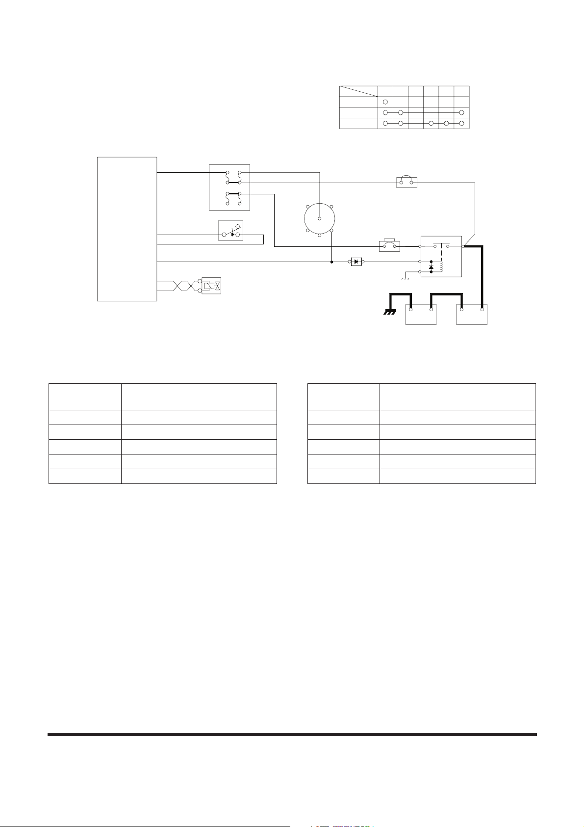
Figure 7 ENGINE STOP CIRCUIT
Reference
Number
Description
1 Battery
2 Battery Relay
3 Fusible Link
4 Circuit Breaker
5 Starter Switch
6 Fuse Box
7 Diode
8 Engine Controller
9 Injector Solenoid
10 Emergency Stop Switch
Reference
Number
Description
Page 22
SP001038Electrical System
Page 20
CHARGING SYSTEM
When the starter switch (5) is turned to the "ON" position, an
initial excited current flows to the field coil of the alternator (7)
through the battery relay (2) and circuit breaker (4). When the
engine is started from this condition the alternator (7) starts
charging. The current flows from the "B(B+)" terminal of
alternator (7) o circuit breaker (4) o battery relay (2) obattery
(1).
The alternator also supplies electric current to other electrical
components. When the alternator (7) starts to operate, a current
flows from the "R(I)" terminal of alternator o diode (8) o battery
relay (2) coil securing a path for the charging current to the
battery (1). Thus preventing the possibility of a high voltage build
up and possible damage to the electric system.
TRIO DIODE
0.5 uF
8
START
ON
OFF
STARTER SWITCH CONNECTION
TML
PST
B BR R1 R2 C ACC
F+
F-
E
REG.
I(L)
FIELD
GRD
7
12V 100AH
R(I)
P(R)
B+
8
B(B+)
-
E
BR
4
B
12V 100AH
1
+ - +
2
A
6
R2
ACC
R1
B
BR
C
5
0.5G
3
FG007238
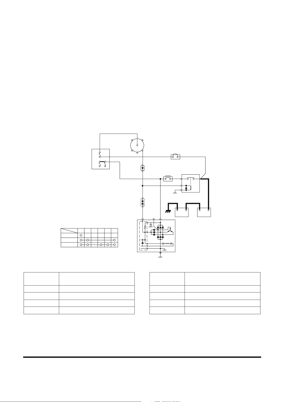
Figure 8 CHARGING CIRCUIT
Reference
Number
Description
1 Battery
2 Battery Relay
3 Fusible Link
4 Circuit Breaker
5 Starter Switch
6 Fuse Box
7 Alternator
8 Diode
Reference
Number
Description
Page 23
SP001038
Page 21
Electrical System
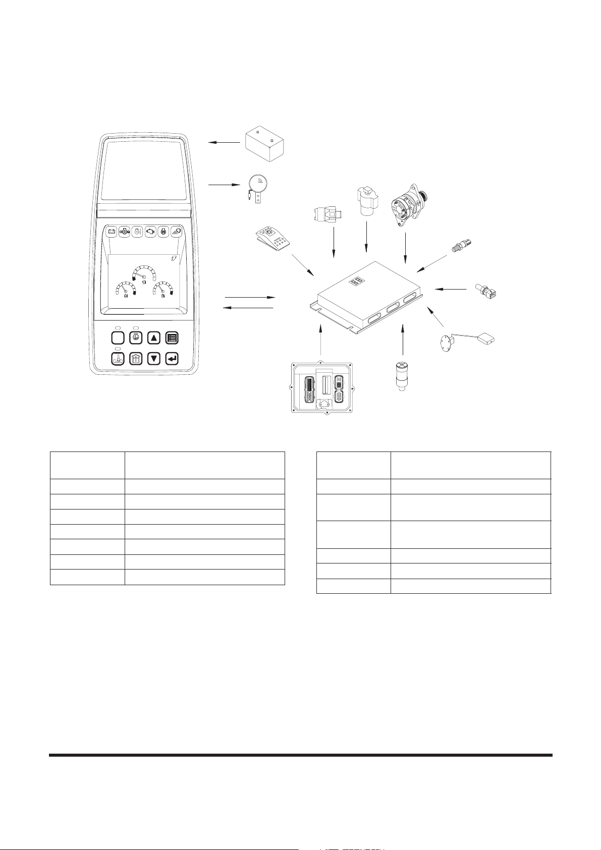
MONITORING SYSTEM
The monitoring system displays the various data and warning
signals onto the instrument panel by processing the information
gathered from the e-EPOS controller. It displays information
selected by the operator.
E
B
+
-
R
C
H
E
F
H
C
POWER
1
5
2
3
6
7
AUTO
4
ESC
8
E/G SPEED
02/05 [MO] 11:30
1700
RPM
CHECK
1
2
8
3
4
5
7
9
10
11
12
13
6
FG000547
Figure 9
Reference
Number
Description
1 Instrument Panel
2 Battery
3 Light Switch
4 Return Filter Switch
5 Pilot Filter Switch
6 e-EPOS Controller
7 Alternator
8 Warning Buzzer
9
Pump Discharge Pressure
Sensor
10
Hydraulic Oil Temperature
Sensor
11 Fuel Sensor
12 Air Cleaner Indicator
13 Engine Controller
Reference
Number
Description
Page 24
SP001038Electrical System
Page 22
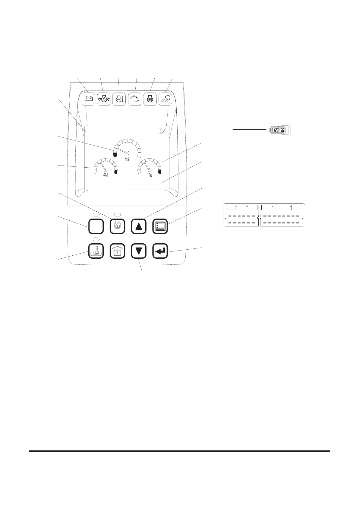
Instrument Panel
C
H
E
F
H
C
POWER
1
5
2
3
6
7
AUTO
4
ESC
8
FG000548
E/G SPEED
02/05 [MO] 11:30
1700
RPM
CHECK
7 8 9 10 11 12
5
1
2
15
13
14
3
6
4
17
19
20
16 18
(CN7)
< CONNECTOR AND TERMINAL NO.>
12
6 5114
10 14
8 7
1516
2 1
8 739 12
5 4 3 2 1
1011 9
6
13
(CN6)
AMP 040 28P
1
Figure 10
Page 25

SP001038
Page 23
Electrical System
When the engine starter switch is turned to the "I" (ON) position,
all gauge bands, switch/button indicator lights and indicator/
warning lights will turn "ON" and the alarm buzzer will sound
about two seconds.
During this functional check, a LOGO will appear on the multi
function gauge in the graphic information area
Gauges Warning Lights Mode Selector Switches
1. Fuel Gauge
2. Engine Coolant Temperature
Gauge
3. Hydraulic Oil Temperature
Gauge
4. Multifunction Gauge and
Letter Information Area
5. Digital Clock
6. Hour Meter
7. Charge Warning Light
8. Engine Oil Pressure Warning
Light
9. Coolant Temperature
Warning Light
10. Engine Check Warning Light
11. Preheat Indicator Light
12. Work Light Indicator Light
13. Power Mode Selector Switch
and Indicator
14. Work Mode Selector Switch
and Indicator
15. Auto Idle Switch and
Indicator
16. Flow Adjusting Switch
17. Up Button Switch
18. Down Button Switch
19. Display Selector Switch
20. Selector Button Switch
Page 26
SP001038Electrical System
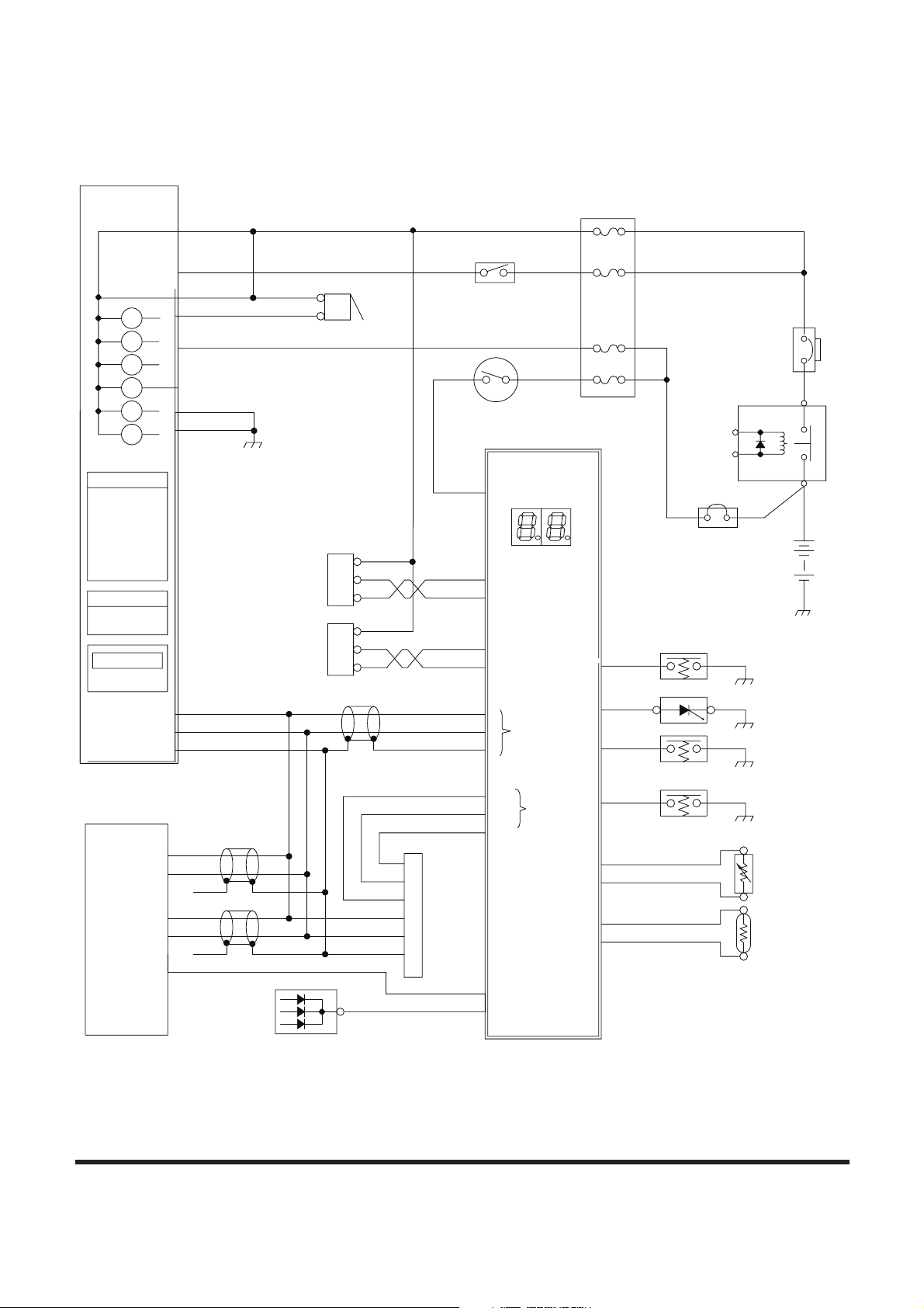
Page 24
Monitoring System Schematic
B
SIG
SIG
1-35
1-34
1-53
1-52
L5
L6
WARNING LAMP
L1 : CHARGE
L5 : PREHEAT
L2 : ENG OIL PRESS
L4 : E/G WARNING
L3 : W/T OVER HEAT
WATER TEMPERATURE
LCD DISPLAY PANEL
L6 : WORK LAMP
GRAPHIC DISPLAY
FUEL LEVEL
CN7-4
CN7-5
CN7-6
CN6-10
CN6-9
4
2
1
3
6
5
14
R(I)
CN4-1
CN2-14
CN3-8
CN3-7
CN3-10
CN3-9
CAN A
-
+
CN4-4
CN3-3
CN3-4
CN4-6
CN4-5
CN4-2
CN4-3
+
-
CN2-1
CN3-2
CN3-1
CN5-3
CN2-17
CN2-18
CN5-7
E
BR
A
L1
L3
L2
L4
ILL.
CN6-3
CN6-1
CN6-2
CN6-12
CN6-11
+
-
R2 B
13
21
6
5
20
14
18
7
8
11
10
12
9
15
1
4
2
3
19
17
16
CN5-2
1-56
TxD
RxD
GND
FG007141
Figure 11
Page 27

SP001038
Page 25
Electrical System
Reference
Number
Description
1 Instrument Panel
2 Pilot Buzzer
3 Light Switch
4 Starter Switch
5 Front Pump Pressure Sensor
6 Rear Pump Pressure Sensor
7 Hydraulic Oil Temperature
Sensor
8 Fuel Sensor
9 Pedal Pressure Switch (Optional)
10 Air Cleaner Indicator
11 Pilot Filter Switch
12 Return Filter Switch
13 Alternator
14 e-EPOS Controller
15 Battery
16 Battery Relay
17 Circuit Breaker
18 Fusible Link
19 Fuse Box
20 Check Connector
21 Engine Controller
Reference
Number
Description
Page 28
SP001038Electrical System
Page 26
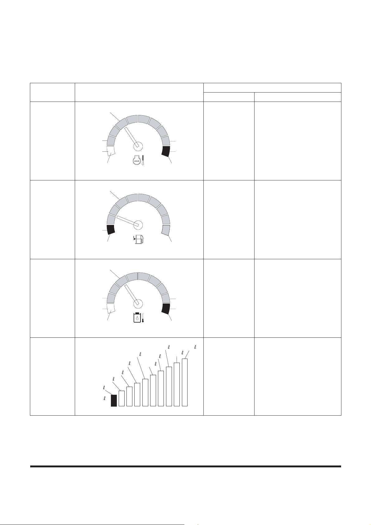
OPERATION
Instruments
Function Display
Sensor Specification
Input Terminal Input Specification
Coolant
Temperature
ECU-CAN
Communication
Fuel Level
CN3-7
CN3-8
1/10 LCD (Red Zone)
Blinking o over 5K ohms
FULL o under 525 ohms
Hydraulic Oil
Temperature
CN3-9
CN3-10
40°C (104°F) o 1,397 ohms
50°C (122°F) o 1,139 ohms
60°C (140°F) o 881 ohms
94°C (201°F) o 190 ohms
96°C (205°F) o 177 ohms
(When reading increase)
Flow
Adjusting
(Output
Terminal)
CN1-19
CN1-20
48.5 l/min o610 mA
57 l/min o583 mA
66 l/min o555 mA
78.5 l/min o466 mA
(Default Set)
108 l/min o343 mA
114 l/min o290 mA
C
H
FG000550
Blue
White Red
107°C
102°C
41°C
61°C
E
F
FG000552
Blue
Red Full
1/10
C
H
FG000551
Blue
White Red
96°C
94°C
40°C
50°C
FG009964
78.5
96.5
106.5
108
(None)
48.5
57
66
69
90
114
114
Page 29

SP001038
Page 27
Electrical System
Tachometer
ECU-CAN
Communication
N = 162 f / 60
N = Engine speed (rpm)
f = Frequency of engine
speed sensor (Hz)
Voltmeter CN2-14 0 - 32 VDC
Main pump
discharge
pressure
(front pump)
CN3-1
CN3-2
V = 0.00816 x P + 1.0
V: Sensor output voltage (V)
P: Displayed pressure (Bar)
Main pump
discharge
pressure
(rear pump)
CN3-3
CN3-4
Function Display
Sensor Specification
Input Terminal Input Specification
E/G SPEED
1700
RPM
FG000049
BATTERY
28.0
VOLT
FG000050
FRONT PUMP
320
BAR
FG000051
REAR PUMP
313
BAR
FG000052
Page 30
SP001038Electrical System
Page 28
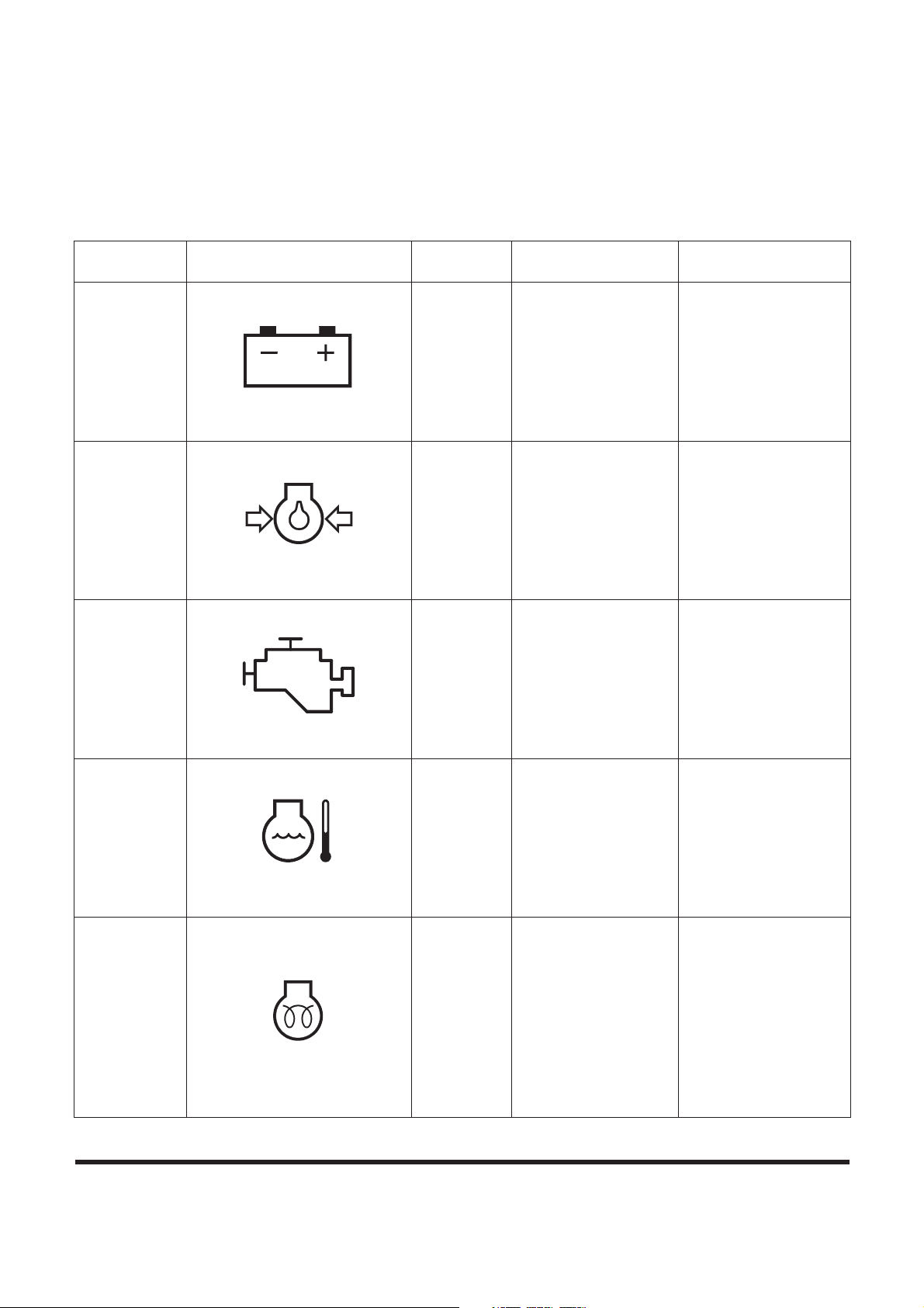
WARNING AND INDICATOR
LIGHTS
Indication of Warning Lights
Description Symbol
Input
Terminal
Operation Remarks
Charge CN2 - 14
It lights in case of no
charge [voltage of
"R(I)" terminal is
below 12 ±1V] or
overcharge [voltage
of "R(I)" terminal is
above 33(V)].
Normally, it lights
when starting engine
and is out after engine
starts.
Engine Oil
Pressure
ECU-CAN
Communic
ation
It lights when engine
oil pressure is below
the reference.
After starting engine,
if engine oil pressure
is insufficient after 8
seconds, a warning
buzzer will sound.
Engine
Check
ECU-CAN
Communic
ation
It lights in case of
failure in engine
system.
Coolant
Temperature
ECU-CAN
Communic
ation
It lights when engine
coolant temperature
sensor resistant is
below about 128
ohms.
Preheating CN5-2
It lights during
preheating ("CN5-2"
terminal voltage is
below 2V) and turns
"OFF" after
completion of
preheating.
Preheating period
depends on coolant
temperature.
No preheating at
above 10°C
10 sec preheating at
5°C
20 sec preheating at
below 0°C
HAOA610L
HAOA620L
CHECK
FG000045
HAOD350L
HAOA639L
Page 31

SP001038
Page 29
Electrical System
Indication of Multifunction Gauge and
Letter Information Area
Work Light CN2 - 6
It lights when work
light turns "ON" (24V
applied).
Description Symbol
Input
Terminal
Operation Remarks
HB4O2003
Description Symbol
Input
Terminal
Operation Remarks
Hydraulic Oil
Temperature
CN3-9
CN3-10
When hydraulic oil
temperature is above
about 96°C.
Fuel
Exhausted
CN3-7
CN3-8
When fuel is almost
exhausted.
Air Cleaner CN2-17
When air cleaner is
clogged.
Return Filter CN5-3
When return filter
pressure is above
about 1.50 kg/cm²
(21 psi)
FG000056
FG000057
FG000053
FG000054
Page 32

SP001038Electrical System
Page 30
Pilot Filter CN2-18
When pilot filter
pressure is above
about 1 kg/cm² (14
psi)
Overload
Warning
CN3-5
CN3-6
Warning buzzer also
starts when boom
pressure sensor
output voltage is
about 2.7V while
overload warning
switch is "ON."
It flickers in case of
2.71V and above and
lights continuously in
case of 2.8V and
above (and warning
buzzer also starts).
Boost CN2-2
It lights when boost is
selected.
Breaker CN2-10
It lights when breaker
is selected.
Shear CN2-9
It lights when shear is
selected.
FG000055
FG000253
FG000554
FG00147
0
FG001471
Page 33

SP001038
Page 31
Electrical System
INITIAL OPERATION
NOTE: Refer to method for setting clock in operation manual
for setting time.
MODE SELECTOR SWITCH
Power Mode / Trenching Mode Switch
NOTE:
When the engine speed is below 1,000 rpm, the output
current of E.P.P.R valve is fixed to be 600 ±60mA.
Auto Idle Switch
Item Input (Terminal) Output (Operation and initial setting mode)
Initial
Operation
When "CN6-1,2" is applied
battery voltage (starter switch
shifts from "OFF" to "ON"
! LCD, all of LED and warning lights are turned
"ON" and turned "OFF" after about 2 seconds.
! Warning buzzer is activated and turned "OFF"
after about 2 seconds.
! Power mode: Standard mode.
! Work Mode: Digging mode.
! Auto Idle: High Output (Activation).
! Display: Indicating coolant temperature, Fuel
level, Hydraulic oil temperature, Engine speed.
! Clock: Current time display.
Operation Mode
Output Check
(Operation
mode display
LED)
e-EPOS Output
Electromagnetic
Proportional Pressure
Reducing Valve (E.P.P.R
Valve) Current (mA)
Swing Priority
Solenoid Valve
7-Segment
Display
Power
Mode
Power Mode ON
No-load: 150 ±20mA
Load: Variable output
(Max. current: 600 ±20mA)
- 9 x
Standard Mode OFF
No-load: 250 ±20mA
Load: Variable output
(Max. current: 600 ±60mA)
- 7 x
Work
Mode
Trenching Mode OFF - ON x 2
Digging Mode ON - OFF x 0
Operation Mode Output Check (Operation mode display LED)
Auto Idle
Activation ON
Cancellation OFF
Page 34

SP001038Electrical System
Page 32
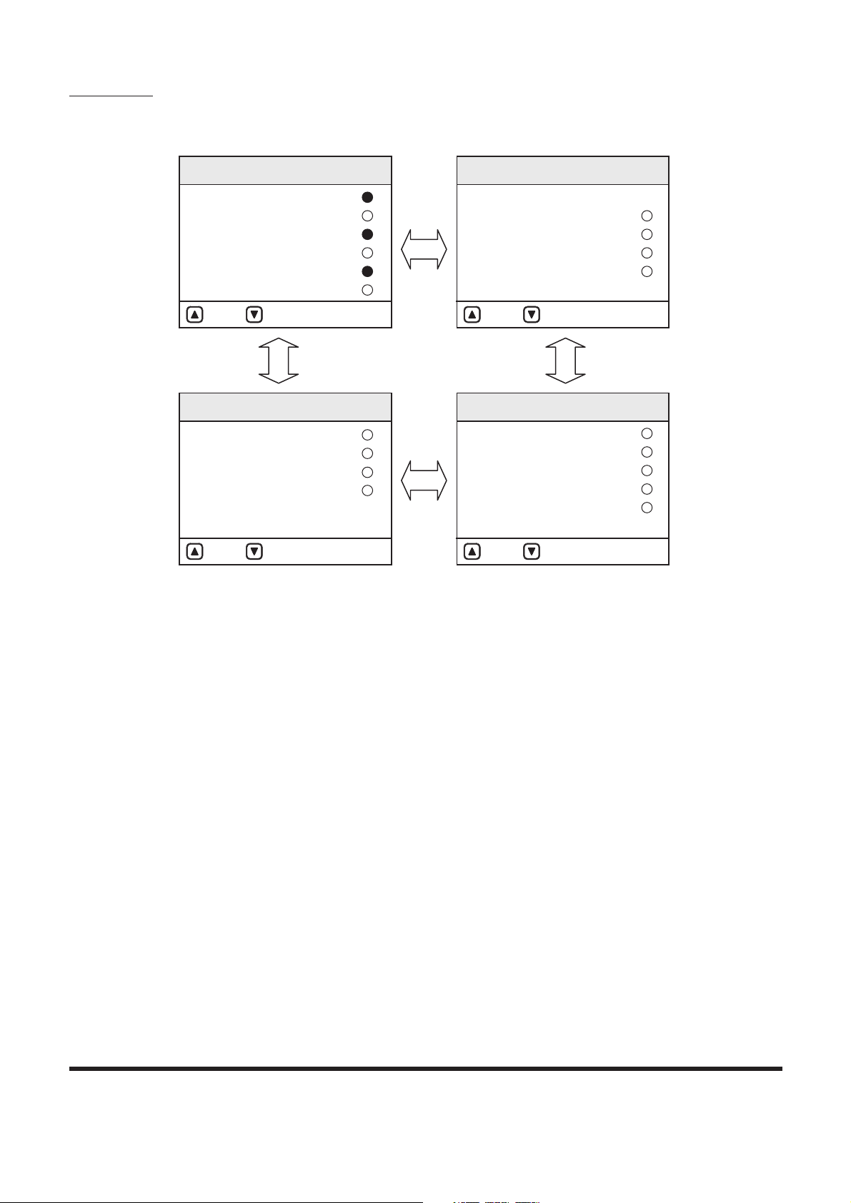
GRAPHIC INFORMATION AREA
DISPLAY
Overview
Many kinds of condition of machine are displayed on the letter
information display department. The information display
department is divided into two menus. One is main menu for
user and the other is special menu for specialist. These menus
can be moved from normal display mode by the combination of
selector buttons.
C
H
E
F
H
C
POWER
1
5
2
3
6
7
AUTO
4
ESC
8
FG000557
E/G SPEED
02/05 [MO] 11:30
1700
RPM
CHECK
5
1
4
3
2
Figure 12
Selector Buttons Graphic Display Area
1. Up Arrow Button
2. Down Arrow Button
3. Enter Button
4. Escape Button
5. Letter Information Display Department
Page 35

SP001038
Page 33
Electrical System
Main Menus for the Graphic Display Area
1. Main menu: Language setting, Time setting, Filter/Oil
information, Brightness adjustment, Password
2. Special menu: Information of machine status, failure
information, Information of machine operation.
Menu Selector Buttons
1. Up Arrow Button ( , 1 on Figure 12): Move the cursor to
up, left and previous screen.
2. Down Arrow Button ( , 2 on Figure 12): Move the cursor
to down, right and next screen.
3. Enter Button ( , 3 on Figure 12): Move the menu to
selected mode. When setting the menu, this button is used
to function as the selector button.
4. Escape Button (ESC, 4 on Figure 12): Move a screen to
previous menu or main menu.
Page 36
SP001038Electrical System
Page 34
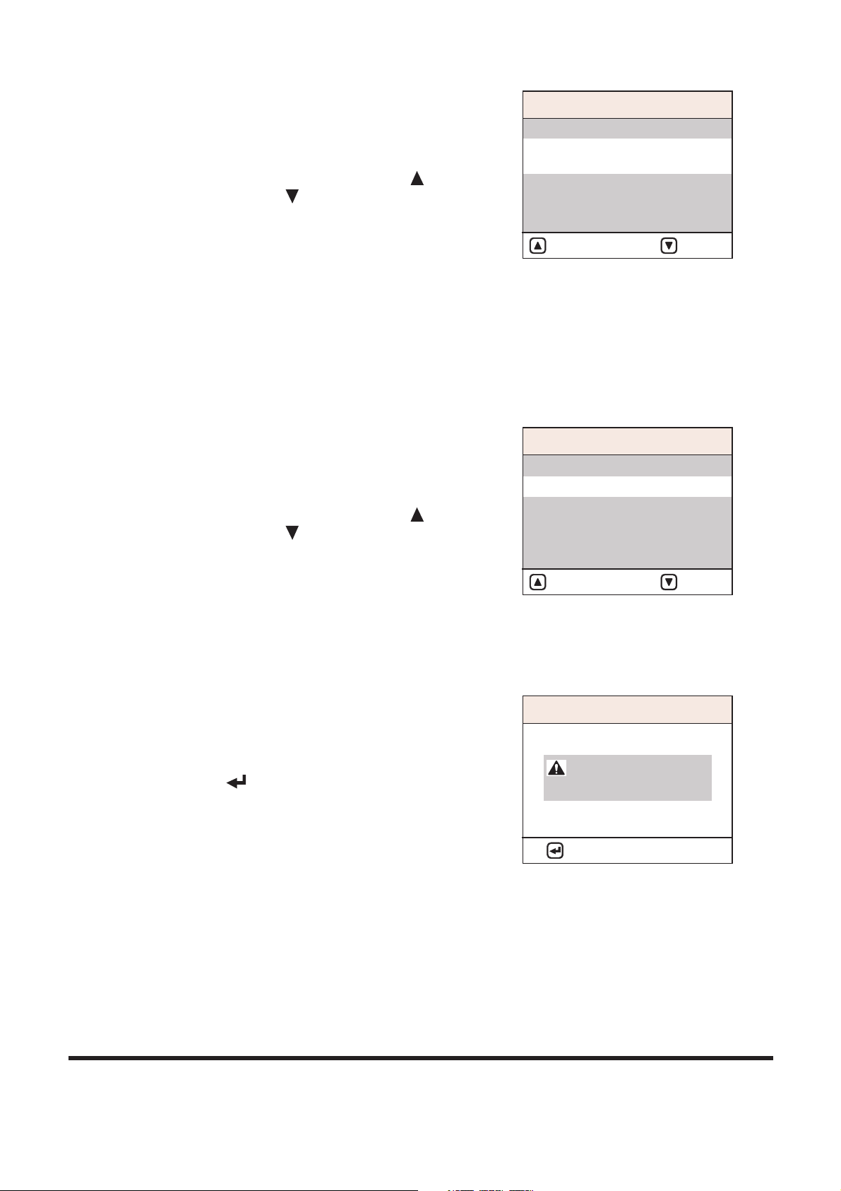
MAIN MENU
When the "ESC" button is pressed for more than 3 seconds, the
main menu screen is displayed.
Main menu offers sub-menus (language setting, time setting, or
filter/oil information, brightness adjustment, password) to the
operator.
Refer to the "Operation and Maintenance Manual" for details.
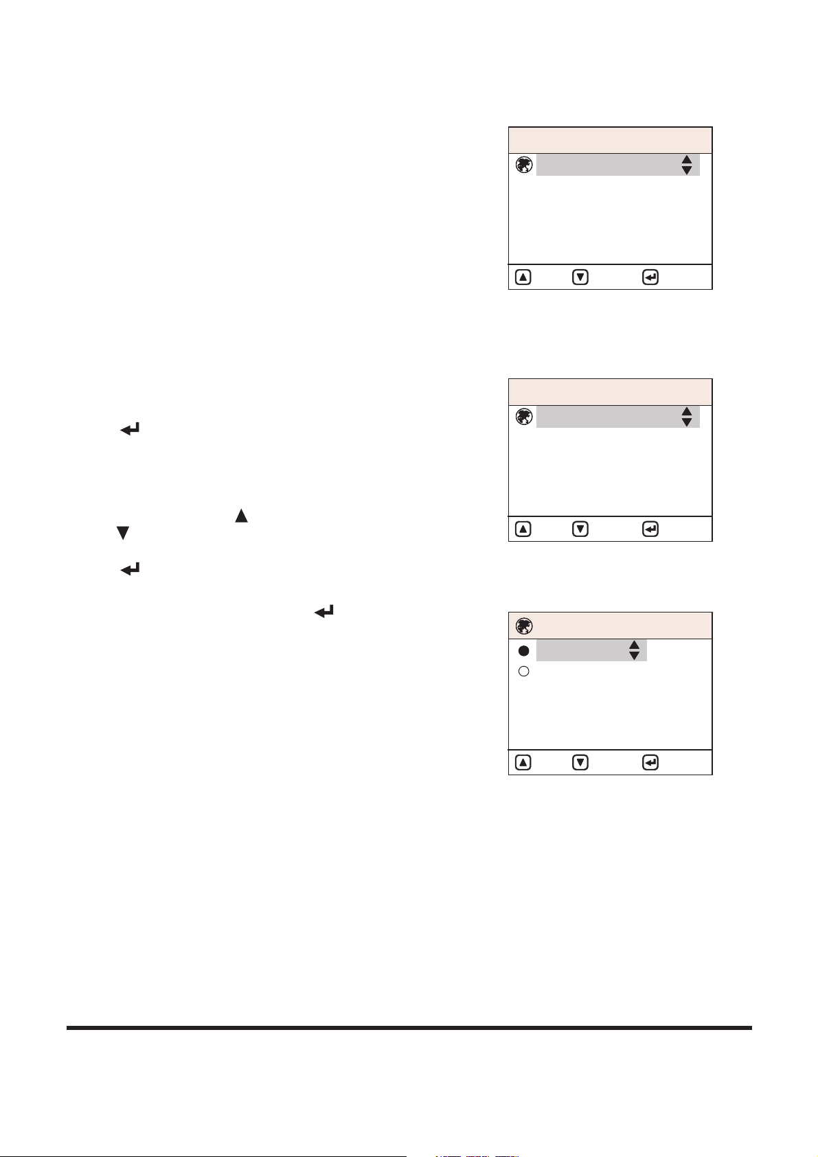
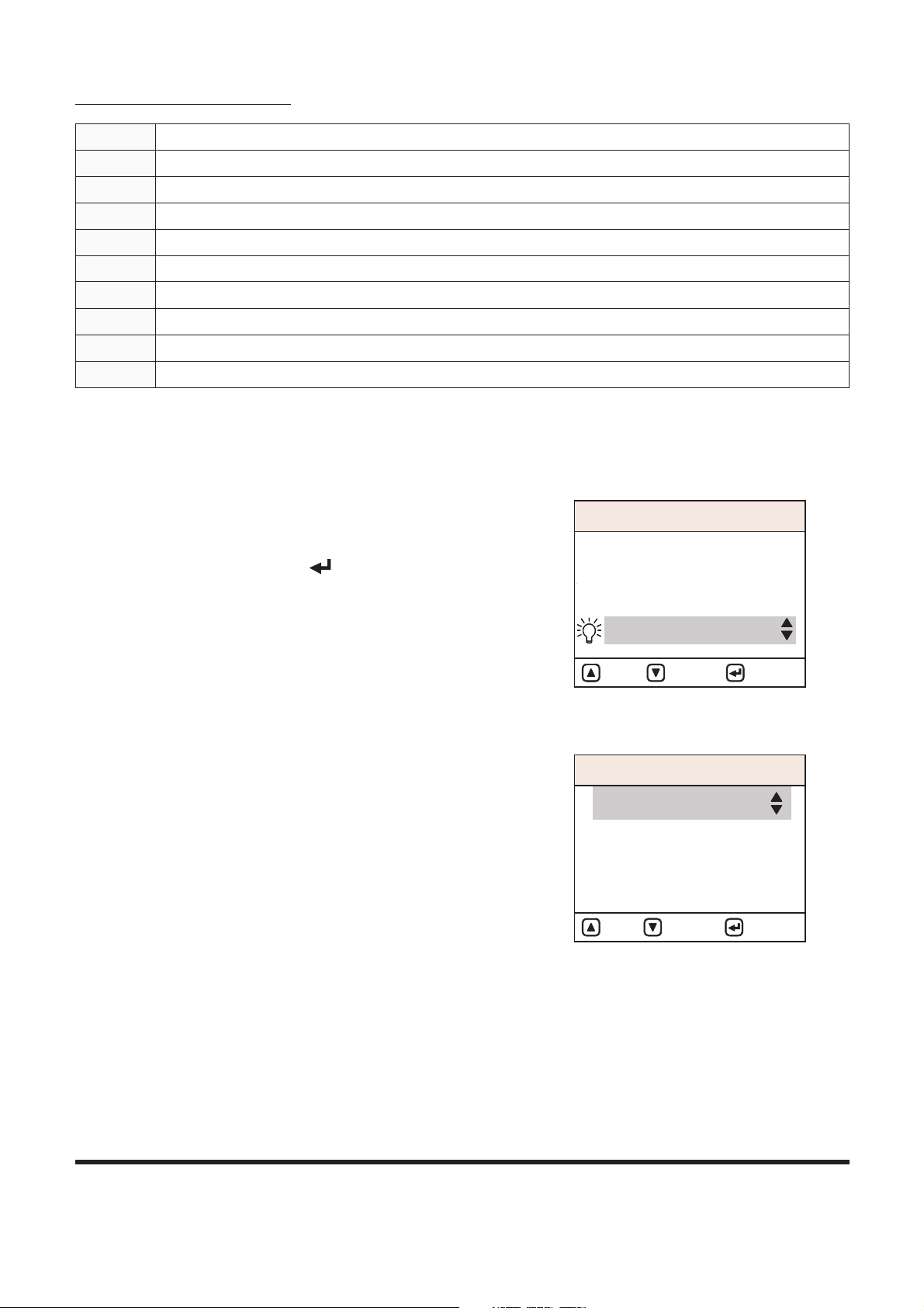
Language
Put the cursor on Language in the main menu and put the Enter
Button ( , 3 on Figure 12) and the language select view
appears.
The default language is Korean, but it will memorize and use the
newly set language.
Use the Up Arrow Button ( , 1 on Figure 12) or Down Arrow
Button ( , 2 on Figure 12) to move cursor to a language to be
selected on the Language Select display and press the Enter
Button ( , 3 on Figure 12) and the selected language is
indicated in the right bottom of the screen.
At this point pressing the Enter Button ( , 3 on Figure 12) or
the Escape Button (ESC, 4 on Figure 12) more than 1 second
brings the main menu with changed language and then pressing
the ESC button again shows the default view.
Without pressing a button more than 20 seconds, the default
view appears.
MA I N ME N U
1. Language
4. Adjust Display
5. Set Password
2. Set Clock
3. Filter / Oil Info
: UP : D OWN : SELE CT
FG0000 72
Figure 13
MA I N ME N U
1. Language
4. Adjust Display
5. Set Password
2. Set Clock
3. Filter / Oil Info
: UP : D OWN : SELE CT
FG0000 72
Figure 14
1. Korean
2. English
: UP : D OWN : SELE CT
FG0007 83
Figure 15
LA N G UAG E
Page 37

SP001038
Page 35
Electrical System
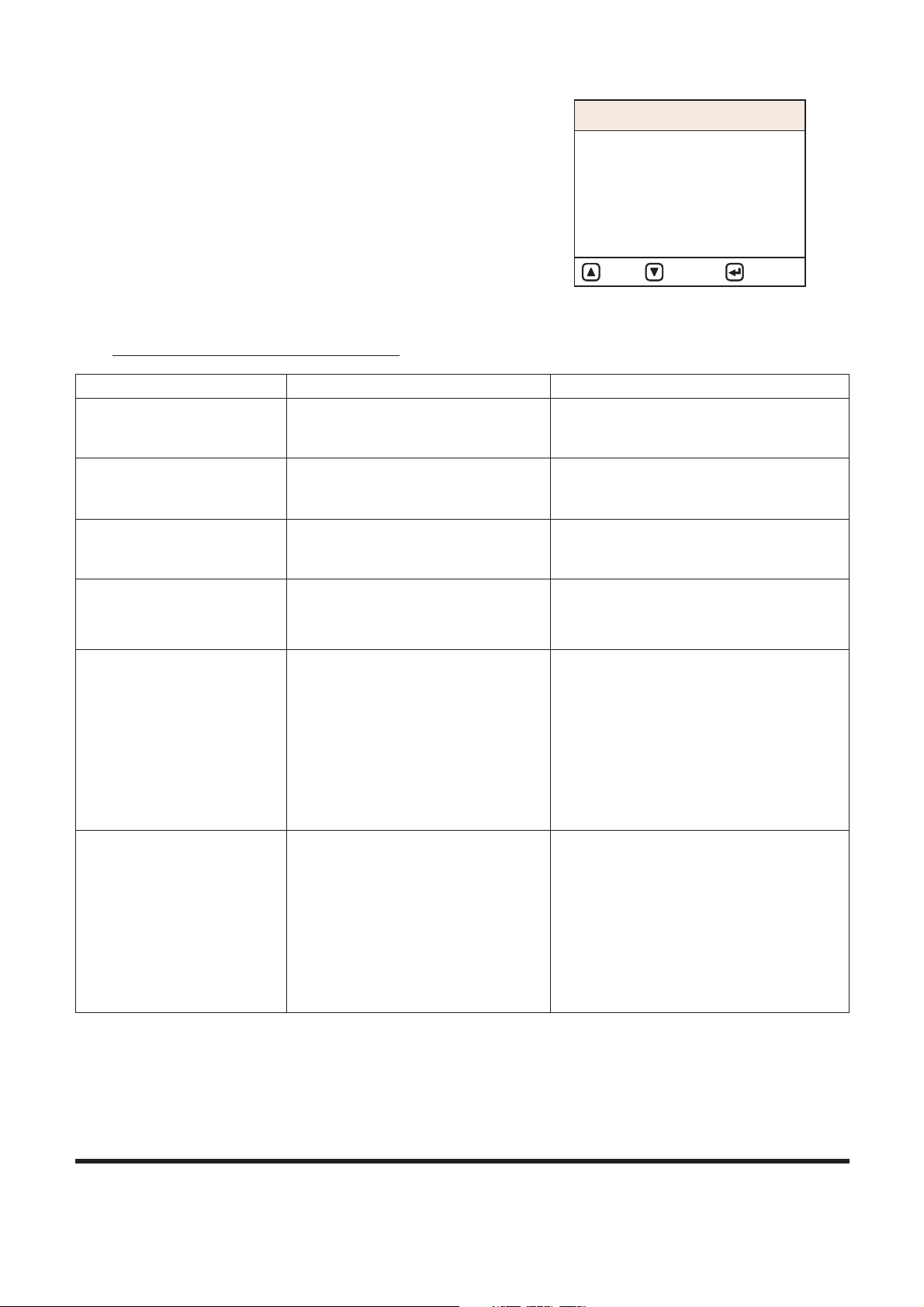
Set Clock
It is used to adjust time of the digital clock.
Pressing the Enter Button ( , 3 on Figure 12) in the Main
Menu after putting cursor on Set Clock brings Set Clock display.
Without pressing a button more than 20 seconds, the default
view appears.
Please refer to the Operation Manual for detailed information on
Time Setting.
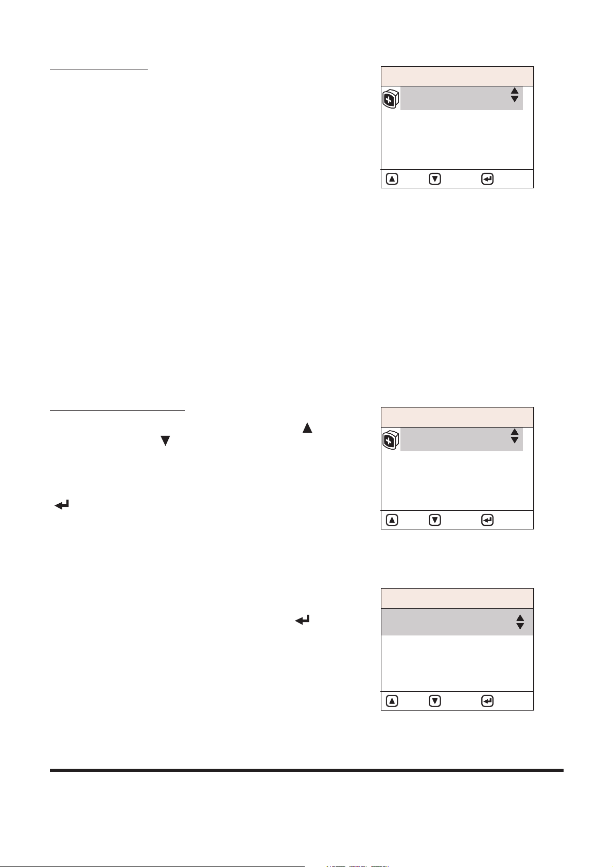
Filter/Oil Info
This mode displays total operating hours of filters and oils.
After changing the filter and oil, reset the operating hour and
then the operating hours until the next service interval can be
easily checked.
MA I N ME N U
1. Language
4. Adjust Display
5. Set Password
2. Set Clock
3. Filter / Oil Info
: UP : D OWN : SELE CT
FG0000 75
Figure 16
SE T CLO C K
:
+
: : MOVE
FG0000 76
0 6 : 0 5
2004 0 6 / 29
Figure 17
MA I N ME N U
1. Language
4. Adjust Display
5. Set Password
2. Set Clock
3. Filter / Oil Info
: UP : D OWN : SELE CT
FG0000 77
Figure 18
FI LTE R / O I L I N FO
: UP : D OWN : RESE T
FG0000 78
1. Fuel F ilter
Hrs : 002 5
Figure 19
Page 38

SP001038Electrical System
Page 36
Menu Display Order and Icon Explanation
Adjust Display
Pressing the Enter Button ( , 3 on Figure 12) in the main
menu after putting cursor on Adjust Display brings Adjust
Display.
Screen brightness can be adjusted using the Up Arrow Button
( , 1 on Figure 12) or the Down Arrow Button ( , 2 on Figure
12).
The default brightness is set to 50%.
1. Fuel Filter 2. Air Cleaner 3. Engine Oil Filter 4. Hyd. Oil Filter
5. Pilot Filter 6. Engine Oil 7. Hydraulic Oil 8. Coolant Water
FG001358
Figure 20
MA I N ME N U
1. Language
4. Adjust Display
5. Set Password
2. Set Clock
3. Filter / Oil Info
: UP : D OWN : SELE CT
FG0000 80
Figure 21
Ad j u st D i sp l a y
:
+
+
:
FG0000 81
50 %
LC D T ES T
LC D T ES T
LC D T ES T
Figure 22
Page 39

Set Password
1. Language
4. Adjust Display
5. Set Password
2. Set Clock
3. Filter / Oil Info
: UP : D OWN : SELE CT
FG0002 27
Figure 23
This menu is used to apply (lock), release, or change password.
Please refer to the Operation Manual for detailed information on
Password Setting.
MA I N ME N U
Electrical System
SP001038
Page 37
Page 40

SP001038Electrical System
Page 38
SPECIAL MENU
In this menu, many types of operating conditions and functions
can be accessed and displayed, including the e-EPOS
controller. This menu is mainly used for machine testing and
failure diagnostics.
The special menu offers three sub-menus:
1. Machine status.
2. Failure information.
3. Information on machine operation.
Entering/Accessing and Exiting/Escaping
Menus
Entering/Accessing Menus
When normal mode screen is displayed, if the enter button ( ,
3) and escape button (ESC, 4) are pressed simultaneously for
more than 3 seconds, normal mode screen (Figure 25) will be
changed to special menu screen (Figure 26).
Normal Mode Screen
NOTE: Normal mode screen can display many kinds of
display mode by selecting, for example, engine
speed (RPM), battery voltage (VOLT), front pump
pressure (BAR), rear pump pressure (BAR) and so
on by selecting.
1
5
POWER
3
2
6
7
AUTO
4
ESC
8
FG001402
3
4
2
1
Figure 24
C
H
C
E
F
H
02/05 [MO] 11:30
E/G SPEED
1700 RPM
FG000043
Figure 25
Page 41
SP001038
Page 39
Electrical System
Special Menu Screen
NOTE: Displayed language on the special menu screen
consists of Korean and English.
If any language except for Korean is selected during
language selection mode of main menu, only English
will be displayed on special menu screen.
Exiting/Escaping Menus
1. If escape button (ESC, 4 on Figure 24) is pressed for more
than 1 second, the special menu screen will be returned to
the normal mode screen.
2. If this special menu is "ON" without any activity, for more
than 20 seconds, it will turn to the normal mode screen.
3. After the turning starter switch to the "OFF" position, turn it
back to the "ON" position, and the normal mode screen
displayed once again.
Special Menu Selections
Submenu Selection Method
Various sub-menus can be selected by pressing "Up ( , 1 on
Figure 24)" and "Down ( , 2 on Figure 24)" button.
Move the cursor to desired menu and a selected menu will be
inverse displayed.
When the selected menu is inverse displayed, press the "Enter
( , 3 on Figure 24)" button for menu selection.
Information of Machine Status
1. Entering Sub-menus: When cursor is located on "Machine
Info" of special menu screen, press "Enter ( , 3 on
Figure 24)" button and the "Machine Info" will be displayed.
2. Exiting Sub-menus: If escape button (ESC, 4 on Figure 24)
is pressed for more than 1 second, display will be turned to
previous screen.
SP E C IAL ME N U
1. Machine Info
2. Failure Info
3. Operating Hrs
: UP : D OWN : SELE CT
FG0005 58
Figure 26
SP E C IAL ME N U
1. Machine Info
2. Failure Info
3. Operating Hrs
: UP : D OWN : SELE CT
FG0005 58
Figure 27
MA C H INE I NF O
1. Analogue Input State
2. Digital Input State
3. Digital Output State
: UP : D OWN : SELE CT
FG0005 59
Figure 28
Page 42
SP001038Electrical System
Page 40
Analog Inputs Description
Submenu Selections
Analog Input Items Display Remark
1. Pump P/V mA Current in pump proportional valve.
2. Cooling Fan P/V mA N.A.
3. Flow Control P/V mA N.A.
4. Dial mV Indicating dial voltage.
5. TPS mV N.A.
6. E/G Control Motor mV N.A.
7. Boom Pressure BAR Boom cylinder head pressure.
8. Pilot Gear Pump Press BAR N.A.
9. Boost Pressure BAR Pump pressure for boost.
10. Intake Manifold Temperature °C Temperature of air incoming to
intake manifold.
11. E/G Oil Pressure BAR Engine oil pressure.
12. Fuel Temperature °C Fuel temperature.
13. E/G Oil Temperature °C Engine oil temperature.
14. Load At Cur. Spd % Current load ratio of equipment.
FG008126
AN A L OG I N PUT S T ATE
: UP : DOWN Page:3/3
1. Pump P/V
2. Cooling Fan P/V
3. Flow Control P/V
4. Dial
5. TPS
6. E/G Control Motor : N.A
7. Boom Pressure
8. Pilot Gear Pump Press.
9. Boost Pressure
11. E/G Oil Pressure
14. Load at Cur. Spd : 000 %
AN A L OG I N PUT S T ATE
AN A L OG I N PUT S T ATE
10. Intake Manifold Temp.
12. Fuel Temp.
13. E/G Oil Temp.
: 000mA
: 000mA
: N.A
: N.A
: 000mV
: 000mA
: 000 C
: 000 C
: 000 C
: 000BAR
: 000BAR
: 000BAR
Figure 29
: UP : DOWN Page:1/3 : UP : DO WN Pag e:2/3
Page 43

SP001038
Page 41
Electrical System
Digital Inputs Descriptions
Digital Inputs Items Mark Remark
1. Alternator
ON / OFF
Lights up when output at alternator
"R(I)" terminal is above 12 ±1V.
2. Travel Select SW N.A. (only for wheel type equipment)
3. High Speed Sel. SW (M)
Lights up when the travel speed
selector switch is set to the "I"
position.
4. High Speed Sel. SW (A)
Lights up when the travel speed
selector switch is set to the "II"
position.
5. Pressure SW (Py)
Lights up when the pressure switch
(Py) is "ON."
6. Pressure SW (Px)
Lights up when the pressure switch
(Px) is "ON."
7. E/G Oil Press. SW N.A. (only for mechanical engine)
8. Air Cleaner Clogged
Lights up when the air cleaner
indicator contact is "ON."
9. Return Filter Clogged
Lights up when the return filter
pressure switch is "ON."
10. Pilot Filter Clogged
Lights up when the pilot filter
pressure switch is "ON."
11. OWD Warning SW
Lights up when the overload
warning selector switch is "ON."
12. Brake Oil Press. SW N.A. (only for wheel type equipment)
13. Pedal Press. SW
Lights up when the pedal pressure
switch is ON.
14. One Way Sel. SW
Lights up when the selector switch is
turned to breaker.
15. Two-way Sel. SW
Lights up when the Selector Switch
is turned to "SHEAR."
16. Power Max. SW
Lights up when the boost button is
"ON" with the Select switch turned
to "BOOST."
17. Breaker SW
Lights up when the boost button is
"ON" with the selector switch turned
to "BREAKER."
18. Preheat Select N.A.
19. Quick Coupler
Lights up when the Quick Coupler
switch is "ON."
20. F and R Lever N.A. (only for wheel type equipment)
21. Preheat Select
Lights up during preheating (CN5-2)
terminal voltage is below 2V.
22. Reverse Fan SW N.A.
23. Pilot Cutoff SW N.A.
Page 44
Menu Select
: UP : DOW N Page:1/ 4
: UP : DOW N Page:3/ 4
1. Alte rna tor
2. Travel Select SW
3. High Sp eed Sel. SW (M)
4. High Sp eed Sel. SW (A)
5. Pres sur e SW (Py)
6. Pres sur e SW (Px)
:
:
:
:
:
:
19. Qui ck Coupler
20. F&R Le ver
21. Pre hea t Select
22. Rev ers e Fan SW
23. Pil ot Cutoff S W
:
:
:
:
: N.A
7. E/G Oil Pr ess. SW
8. Air Cle aner Clogged
9. Retu rn Filter Clogged
10. Pil ot Filter Clogged
11. OWD Warning SW
12. Bra ke Oil Press. SW
: N.A
:
:
:
:
: N.A
13. Ped al Press. SW
14. One Way Sel. SW
15. Two Way Sel. SW
16. Pow er Max. SW
17. Bre ake r SW
18. Pre hea t Select
:
:
:
:
:
: N.A
DI G I TA L INP U T STAT E
DI G I TA L INP U T STAT E DI G I TA L INP U T STAT E
Figure 30
DI G I TA L INP U T STAT E
: UP : DOW N Page:2/ 4
: UP : DOW N Page:4/ 4
FG008136
Page 42
SP001038Electrical System
Page 45

SP001038
Page 43
Electrical System
Digital Outputs Descriptions
Menu Select
Failure Information
1. Entering Sub-menus: When a cursor is located in "Failure
Info" of special menu screen press enter button ( , 3 on
Figure 24) and "Failure Info" screen is displayed.
2. Exiting Sub-menus: If escape button (ESC, 4 on Figure 24)
is pressed for more than 1 second, this information screen
will be returned to previous screen.
* Real-time Failure:
Current status of failure is displayed.
* Failure Log:
Memorized record of past failure is displayed.
* Delete Fail Log:
This mode is used to delete all of the
memorized record of past failure.
Digital Outputs Items Mark Remark
1. Relief Press. Up S/V
ON / OFF
Lights up when the relief press up
solenoid valve is "ON."
2. High Speed S/V
Lights up when the high speed
solenoid valve is "ON."
3. Swing Priority S/V
Lights up when the swing priority
solenoid valve is "ON."
4. Reverse Fan S/V N.A.
5. Starter Relay When the starter relay is "ON."
6. After Heat Relay N.A.
: UP : DOWN Page:1 /1
FG0039 30
1. R elief Press. Up S/V
2. H igh Speed S/V
3. S wing Priority S/V
4. R everse Fan S/V
5. S tarter Relay
6. Afterheat Relay
:
:
:
: N. A
:
: N. A
DI G I TA L O U TPU T STATE
Figure 31
SP E C IAL ME N U
1. Machine Info
2. Failure Info
3. Operating Hrs
: UP : D OWN : SELE CT
FG0005 63
Figure 32
FA I L URE I NF O
1. Realtime Fail
2. Failure Log
3. Delete Fail Log
: UP : D OWN : SELE CT
FG0005 64
Figure 33
Page 46
SP001038Electrical System
Page 44
A. Current failure information
Current status of failure is displayed (Failure code,
failure contents).
When a number of failures are produced, failure
information can be checked using "UP" ( , 1 on
Figure 24) or "DOWN" ( , 2 on Figure 24) button.
* 1/2: A serial number of current failure/ total quantity
of failure.
* Vxxx-xx: Vxxx is a unique code and xx is a FMI
(Failure Mode Identifier) number.
- V: Machine related failure code
- E: Engine related failure code
Refer to the failure information code for unique codes
and FMI numbers.
This example shows one of two failures.
B. Past failure information
Memorized record of past failure is displayed (Failure
code, failure contents).
When a number of failures are produced, failure
information can be checked using "UP" ( , 1 on
Figure 24) or "DOWN" ( , 2 on Figure 24) button.
NOTE: " Number: xxx ": "xxx" means that the
totally counted number of the same failure.
" Period:xxxxxHrxxm ": It indicates the
period for which machine has operated
until a failure takes place. (For more than
two occurrences of the same failure, until
the first occurrence time.)
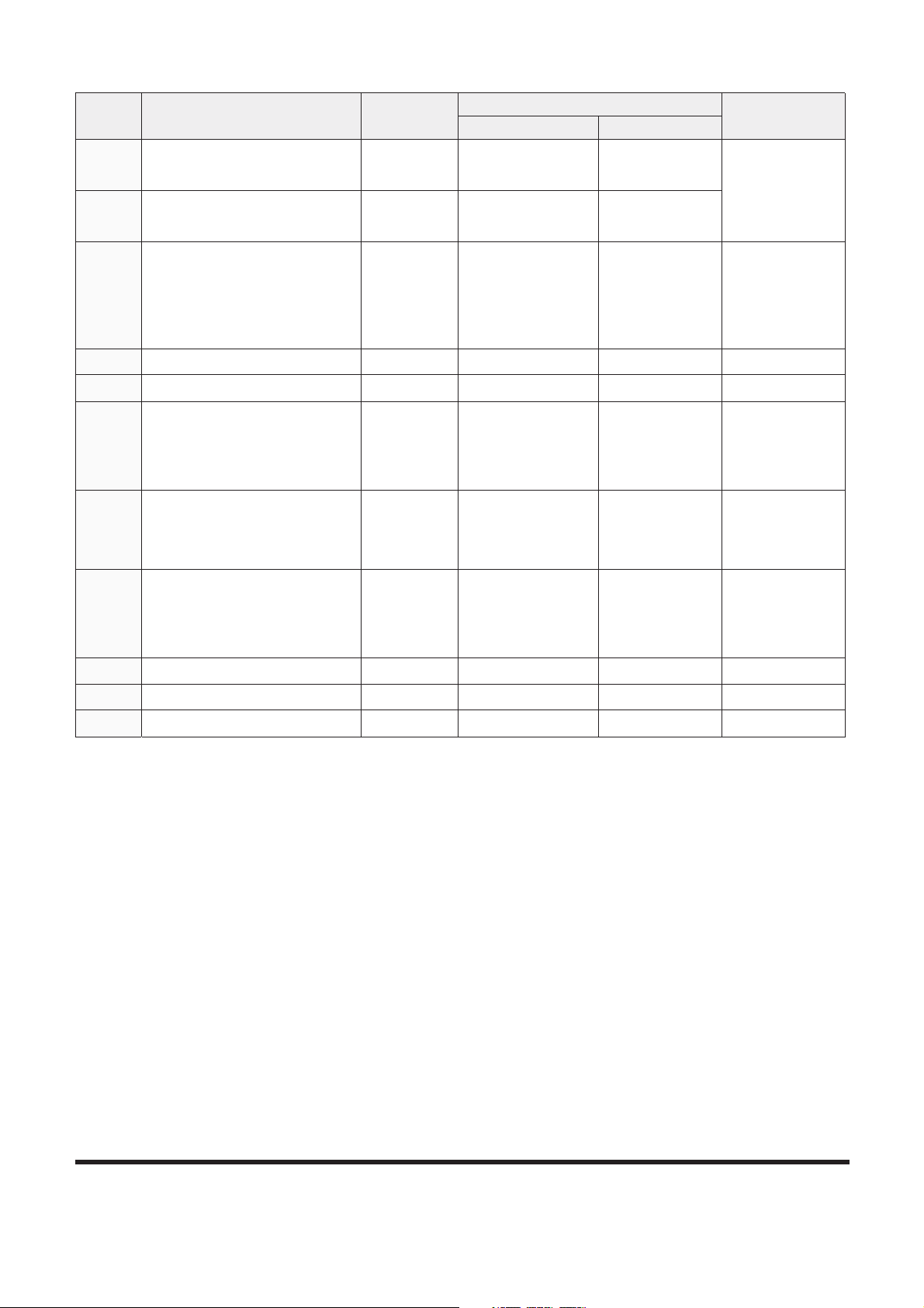
C. Failure record deletion
This mode is used to delete the memorized record of
past failure. If this mode is selected, all records will
be deleted.
When "YES" ( , 3 on Figure 24) button is pressed,
the memorized record will be deleted.
At this time, deletion signal will be displayed and the
screen will move to previous menu after deletion.
This screen will be displayed during 3 seconds.
RE A LT I M E FA I L
: UP : DOWN
FG0005 65
1/ 2 CO DE : V2 04 -0 5
2/ 2 CO DE : E0 11 - 04
Re li ef Pr es su r e Up S / V
Cu rr en t b el ow no rm al (C UR RE N T
BE LO W N OR MA L or o p en c ir c ui t)
Figure 34
: UP : DOWN
FG0005 66
1/ 2 CO DE : V2 04 -0 5
2/ 2 CO DE : E0 11 - 04
Pe ri od : 00 25 4H r 2 9m N um be r: 0 8
Re li ef Pr es su r e Up S / V
Cu rr en t b el ow no rm al (C UR RE N T
BE LO W N OR MA L or o p en c ir c ui t)
Figure 35
DELETE FAIL LOG
ESC: No
FG0005 67
: Yes
Al l Fai l Lo g wil l be
DE L E TED .
Figure 36
FA I L URE L OG
Page 47

SP001038
Page 45
Electrical System
Input your password with one of No. 1 - 8 switches.
When "NO" (ESC, 4 on Figure 24) button is pressed,
the screen will recover to previous menu without
deletion.
Delete Completed screen will appear 3 seconds and
the screen will move to Failure Info screen.
It has been shown 3 seconds upon deleting Fail Log.
The screen shown on the left will appear 3 seconds in
case of wrong password input and then Enter
Password screen appears again.
It has been shown 3 seconds in case of password
failure.
ESC: No
FG0005 69
: Yes
DE L ET E D!! !
DELETE FAIL LOG
Figure 38
ESC: No
FG0005 70
: Yes
PASSWORD ERR !!!
DELETE FAIL LOG
Figure 39
DELETE FAIL LOG
Figure 37
ENTER PASSWD
: Yes
ESC: No
FG0005 68
Page 48

SP001038Electrical System
Page 46
Failure Information Code at Machine Side
Code Failure Component
Measuring
Points
Correct Value
Remarks
Active Passive
V201
Gauge Panel
Communication Error
CN7-4
CN7-5
- R 60 ±5 :
It is a
composite
resistance of
CAN line. This
value has to be
measured by
connected
condition of
CAN line.
V202
Ecu Communication Error
CN4-4
CN4-5
- R 60 ±5 :
V210
Pump P/V
CN1-10
CN1-21
-
R 18 ±2 :
(25°C (77°F))
Pump
proportional
pressure
reducing valve.
V211
Cooling Fan P/V - -
N.A.
V212
Flow Control P/V
CN1-19
CN1-20
-
R 14 ±2 :
(25°C (77°F))
Flow control
proportional
pressure
reducing valve.
V213
Relief Pressure Up S/V
CN1-1
CN1-11
V = V_volt (Note
4.)
R 26.2 ±2 :
(25°C (77°F))
Breaker/boost/
shear selector
switch has to
be selected as
a boost
function and
the boost
switch on the
right-hand
joystick is "ON"
status.
V214
High Speed S/V
CN1-1
CN1-12
V = V_volt
R 26.2 ±2 :
(25°C (77°F))
Voltage is only
measured
when the
pressure
switch (Py) is
turned "ON."
V215
Swing Priority S/V
CN1-1
CN1-13
V = V_volt
R 26.2 ±2 :
(25°C (77°F))
Work mode
has to be
selected as a
trenching
mode.
V216
Reverse Fan Speed S/V - -
N.A.
V217
Starter Relay
CN1-1
CN1-15
V = V_volt -
It has to be
measured in
engine start up
state.
V218
After Heat Relay - -
N.A.
Page 49
SP001038
Page 47
Electrical System
NOTE: 1. Active value: Starter switch has to be turned "ON"
Measuring points between component and wire
harness have to be connected.
2. Passive value: Starter switch has to be turned
"OFF"
Measuring points between component and wire
harness have to be disconnected.
3. Measuring points are engine controller's points and
passive value is each component's value.
4. V#batt: Source power of equipment.
V220
Front Pump Press. Sensor
CN3-1
CN3-2
V = IV -
It has to be
measured in
engine stop
state.
V221
Rear Pump Press. Sensor
CN3-3
CN3-4
V = IV -
V222
Hyd. Oil Temperature Sensor
CN3-9
CN3-10
-
R 2.45 r25
k: (25°C
(77°F))
R 320 ±32 :
(80°C (176°F))
V223
Water Temperature Sensor - -
N.A.
V224
Engine Speed Sensor - -
N.A.
V225
Fuel Level Sensor
CN3-7
CN3-8
-
Empty: 5 r25
k:
Full: 320 ±32
:
V226
Alternator Potential
CN2-14
CN1-8
V = 2 ±1V -
It has to be
measured in
engine stop
state.
V227
Dial
CN3-16
CN3-7
-
R 1.0 r3
k:
R 4.0 ±1.5
k:
V228
Tps (Wheel) - -
N.A.
V229
Parking Brake Press. Sensor - -
N.A.
V230
E/g Control Motor Sensor - -
N.A.
Code Failure Component
Measuring
Points
Correct Value
Remarks
Active Passive
Page 50

SP001038Electrical System
Page 48
Failure Information Code at Engine Side
Code Failure Component
Measuring
Points
Current Valve
Remarks
Active Passive
E011
Coolant temperature sensor
2-26
2-15
-
R 186 ±5 :
(100°C
(212°F))
E012
Fuel temperature sensor
2-26
2-35
-
R 186 ±5 :
(100°C
(212°F))
E013
Boost air temperature sensor
2-36
2-25
-
R 186 ±5 :
(100°C
(212°F))
E014
Boost air pressure sensor
2-33
2-34
V 1,071 ±58mV
(at 23°C (73°F)
and absolute
pressure 1bar)
-
It has to be
measured in
engine running
state.
E017
E/G oil temperature sensor
2-28
2-24
-
R 186 ±5 :
(100°C
(212°F))
E018
E/G oil pressure sensor
2-32
2-27
V 2,318 ±80mV
(at 23°C (73°F)
and absolute
pressure 3bar)
-
It has to be
measured in
engine running
state.
E021
Battery voltage
1-03
1-06
V = V#volt
(Note 4.)
-
E022
Fuel pressure sensor
3-09
3-10
V 1,833 ±28mV
(at 23°C (73°F)
and absolute
pressure 300bar)
-
It has to be
measured in
engine running
state.
E032
Fuel pressure monitoring
MPROP
2-14
2-12
-
R 2.60 ±3.15
:
(20°C (68°F))
E037
CAN module
1-53 and
1-52
1-35 and
1-34
-
R 60 ±5 :
(20°C (68°F))
It is a composite
resistance of
CAN line.
This value has
to be measured
by connected
condition of
CAN line.
E038
Engine overspeed - -
E039
Main relay (ECU) - -
E041
Redundant shutoff path - -
Abnormal
engine stop.
E042
E/G speed (Crankshaft)
2-23
2-19
-
R 860 ±6 :
(20°C (68°F))
E043
E/G speed (Camshaft)
2-09
2-10
- -
Page 51
SP001038
Page 49
Electrical System
E044
Engine speed sensor - -
Synchronizing
error between
crank shaft
speed sensor
and cam shaft
speed sensor.
E045
EEPROM - -
Data storing
error when
engine stop.
E046
Recovery - -
E047
Monitoring of PRV - -
When the
pressure sensor
of common rail
or
high-pressure
pump has a
defect.
E048
Power supply
1-03
1-06
V = V#volt -
E049
Booster voltage C1 - -
E051
Booster voltage C2 ($6, 2
and 4)
- -
E058
Solenoid power stage 1
3-13
3-04
-
R 0.31 ±0.42
:
(20°C (68°F))
E059
Solenoid power stage 2
3-11
3-06
- -
E061
Solenoid power stage 3
3-05
3-12
- -
E062
Solenoid power stage 4
3-03
3-14
- -
E063
Solenoid power stage 5
3-01
3-16
- -
E064
Solenoid power stage 6
3-02
3-15
- -
E066
Preheat light (E/G: Lowside
Power stage 2)
1-56
1-06
- -
E072
Preheat relay (E/G: Highside
Power stage 1)
1-13
1-07
V = V#volt
R 40 ±5 :
(25°C (77°F))
Voltage is only
measured when
afterheat
function is
operating
status.
Code Failure Component
Measuring
Points
Current Valve
Remarks
Active Passive
Page 52

SP001038Electrical System
Page 50
NOTE: 1. Active value: Starter switch has to be turned "ON"
Measuring points between component and wire
harness have to be connected.
2. Passive value: Starter switch has to be turned
"OFF"
Measuring points between component and wire
harness have to be disconnected.
3. Measuring points are engine controller's points and
passive value is each component's value.
4. V#batt: Source power of equipment.
E083
Fuel HI pressure pump
(E/G: Current controlled
Highside power stage 1)
- - -
Fuel metering
unit error of
high-pressure
pump.
E091
System start-up test for
shutoff path
- - -
Power supply
error
Engine
controller error.
E092
Monitoring of misfire cylinder
1
- - -
Injector error
Speed signal
error of cam
shaft speed
sensor or crank
shaft speed
sensor.
E093
Monitoring of misfire cylinder
2
- - -
E094
Monitoring of misfire cylinder
3
- - -
E095
Monitoring of misfire cylinder
4
- - -
E096
Monitoring of misfire cylinder
5
- - -
E097
Monitoring of misfire cylinder
6
- - -
E098
Monitoring of misfire multiple
cylinder
- - -
E099
Monitoring of overrun - - -
E101
Engine speed redundant - - -
Code Failure Component
Measuring
Points
Current Valve
Remarks
Active Passive
Page 53
SP001038
Page 51
Electrical System
FMIs (Failure Mode Identifier)
Information of Machine Operation
Accumulated operation hour of each mode and status is
displayed.
1. Operating Hour Information
A. Entering Sub-menus: When a cursor is located in
"Operating Hrs" of special menu screen (Figure 40)
press enter button ( , 3 on Figure 24) and
"Operating Hrs" screen will be displayed (Figure 41).
B. Information screen of machine operation (Figure 41).
FMI 0
Above normal range (DATA VALID but ABOVE NORMAL OPERATIONAL RANGE)
FMI 1
Below normal range (DATA VALID but BELOW NORMAL OPERATIONAL RANGE)
FMI 2
Incorrect signal (DATA ERRATIC, INTERMITTENT OR INCORRECT)
FMI 3
Voltage above normal (VOLTAGE ABOVE NORMAL OR SHORTED TO HIGH SOURCE)
FMI 4
Voltage below normal (VOLTAGE BELOW NORMAL OR SHORTED TO LOW SOURCE)
FMI 5
Current below normal (CURRENT BELOW NORMAL OR OPEN CIRCUIT)
FMI 6
Current above normal (CURRENT ABOVE NORMAL OR GROUNDED CIRCUIT)
FMI 8
Abnormal signal (ABNORMAL FREQUENCY OR PULSE WIDTH OR PERIOD)
FMI 11
Failure mode not identifiable (ROOT CAUSE NOT KNOWN - Malfunction)
FMI 31
NOT AVAILABLE OR CONDITION EXISTS
SP E C IAL MEN U
1. Machine Info
2. Failure Info
3. Operating Hrs
: UP : DOW N : SELECT
FG0005 71
Figure 40
OP E R AT I N G H O U RS
Reset Hours
Operating Hours
: UP : D OWN : SELECT
FG0005 72
Figure 41
Page 54
C. Operating Hours Screen
: UP : DO WN : SELECT
FG0005 73
1. Powe r
2. Tr enching
3. Au to idle
4. Travel speed
I speed
I I speed
: 00042 Hr
: 00003 Hr
: 00005 Hr
: 00007 Hr
: 00001 Hr
OP E R AT I N G H O U RS
Figure 42
Item Information Contents Detection Method
Power Mode Operation hours used power mode
are displayed.
Power mode switch (Instrument panel) "ON" status and Alternator signal
(CN2-14) is "HI"
Trenching Mode Operation hours used trenching
mode are displayed.
Trenching mode switch (Instrument
panel) - "ON" status and Alternator
signal (CN2-14) is "HI"
Auto Idle Operation hours used auto idle
status are displayed.
Auto idle switch (Instrument panel) "ON" status and Alternator signal
(CN2-14) is "HI"
Travel Speed:
-1st
- 2nd
Operation hours used low speed
and high speed are displayed.
1st: High speed s/v "OFF" status
2nd: High speed s/v and travel pressure
switch "Py" (control valve) - "ON" status.
Hydraulic Oil Temperature
Distribution (°C (°F))
Temperature of hydraulic oil is
classified 6 steps. And operation
hours of each step are displayed
Under 30°C (87°F)
31 - 50°C (88 - 123°F)
51 - 75°C (124 - 168°F)
76 - 85°C (169 - 186°F)
86 - 95°C (187 - 203°F)
Over 96°C (204°F)
The resistance delivered from
temperature sensor of hydraulic oil is
classified 6 steps. And operation hours
of each step are displayed. (Alternator
output HI status)
Coolant Temperature
Distribution (°C (°F))
Temperature of coolant is classified
6 steps. And operation hours of
each step are displayed.
Under 40°C (105°F)
41 - 60°C (106 - 141°F)
61 - 85°C (142 - 186°F)
86 - 95°C (187 - 204°F)
96 - 105°C (205 - 222°F)
Over 106°C (223°F)
The resistance delivered from coolant
sensor is classified 6 steps. And
operation hours of each step are
displayed. (Alternator output HI status)
D. Exiting Sub-menus: If escape button (ESC, 4 on
Figure 24) is pressed for more than 1 second, this
information screen will be returned to previous
screen.
Information contents of operation hour
Page 52
SP001038Electrical System
Page 55

SP001038
Page 53
Electrical System
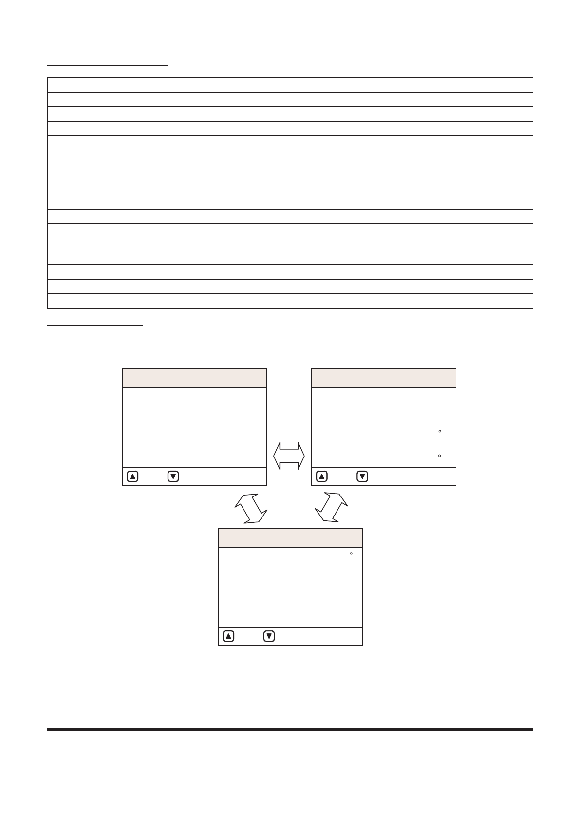
Menu Selection of Operation Hour Information
Example of Machine Operation Info Screen
2. Operation hour reset
A. Entering Sub-menus: When cursor is located in
"Reset Hrs" of information screen of operating hours
press enter button ( , 3 on Figure 24) and
"Machine Operation Info" screen will be displayed.
1. Power Mode
2. Trenching Mode
3. Auto Idle
4. Travel Speed 1st, 2nd
5. Hydraulic Oil Temperature Distribution
6. Coolant Temperature Distribution
FG000574
Figure 43
FG0005 75
OP E R AT I N G H O U RS
: UP : DOWN P age:1/3 : UP : DO WN Page:2/3
: UP : DOWN Page:3/3
1. Powe r
2. Tr enching
3. Au to idle
4. Tr avel speed
I Sp eed
I I S pee d
: 00042 Hr
: 00003 Hr
: 00005 Hr
: 00007 Hr
: 00001 Hr
5. Hyd. Oi l Temp. [ C]
30
31 - 50
51 - 75
86 - 95
96
: 00003 Hr
: 00005 Hr
: 00008 Hr
76 - 85 : 00000 Hr
: 00007 Hr
: 00001 Hr
6. Cool ant Temp. [ C]
40
41 - 60
61 - 85
86 - 95
96 - 105
1 06
: 00003 Hr
: 00005 Hr
: 00000 Hr
: 00000 Hr
: 00007 Hr
: 00001 Hr
OP E R AT I N G H O U RS
OP E R AT I N G H O U RS
Figure 44
Reset Hrs
Operating Hrs
: UP : DO WN : Yes
FG0005 78
OP E R AT I NG H O URS
Figure 45
Page 56

SP001038Electrical System
Page 54
B. Reset screen of operation hour
C. Exiting Sub-menus: If escape button (ESC, 4 on
Figure 24) is pressed for more than 1 second, this
information screen will be returned to previous
screen.
NOTE: When "YES" ( , 3 on Figure 24) button is
pressed, operation hours will reset.
At this time, resetting signal will be displayed
and the screen will move to previous menu after
resetting.
NOTE: When "NO" (ESC, 4) button is pressed, the
screen will recover to previous menu without
resetting.
Machine Operation Info Screen
1. If you press the YES" ( , 3 on Figure 24) button,
password entrance screen appears.
2. When right password is input, machine operation periods
will be deleted and Reset Completed screen will appear 3
seconds.
3. If you press the "NO" (ESC, 4) button, the previous screen
appears without resetting operation periods.
ESC: No
FG0005 76
: Yes
OP E R AT I NG H O URS
ENTER PASSWD
Figure 47
ESC: No
FG0005 77
: Yes
DE L E TED ! ! !
OP E R AT I NG H O URS
Figure 48
ESC: No
FG0010 86
: Yes
PASSWORD ERR !!!
OP E R AT I NG H O URS
Figure 49
OP E R AT I NG H O URS
Figure 46
Al l Ope r ati n g
Ho u r s w i ll b e
DE L E TED .
: Yes
ESC: No
FG0005 79
Page 57

Electrical System
SP001038
Page 55
Page 58

SP001038Electrical System
Page 56
ELECTRONIC HYDRAULIC
CONTROL SYSTEM (e-EPOS)
Control System Schematic
Work Mode
Auto Idle
Machine Info
E/G
E/G speed order
FG000795
POWER UP
C
H
E
F
H
C
POWER
152
3
6
7
AUTO
4
ESC
8
E/G SPEED
02/05 [MO] 11:30
1700
RPM
CHECK
5
44
3
8
8
7 7
16
6 6
11 12 14
13
15
109
2
17 21 19 18 22 20
23
1
Figure 50
Page 59

SP001038
Page 57
Electrical System
Reference
Number
Description
1 Instrument Panel
2 e-EPOS Controller
3 Engine Controller (ECU)
4 Main Pump
5 Aux Pump
6 Control Valve
7 Pressure Switch
8 Pump Pressure Sensor
9
Electromagnetic Proportional
Pressure Reducing Valve
(Attachment)
10
Electromagnetic Proportional
Pressure Reducing Valve (Mode
Control)
11 Solenoid Valve (Boost)
12 Solenoid Valve (Swing Priority)
13 Solenoid Valve (High Speed)
14 Solenoid Valve (Breaker)
15 Travel Motor
16 Main Relief Valve
17 Engine Control Dial
18
Breaker/Boost/Shear Selector
Switch
19 Auto Travel Selector Switch
20
Boost Switch
(Right Work Lever)
21 Sensor
22 Aux Mode Switch
23 Aux Mode Resistor
Reference
Number
Description
Page 60

SP001038Electrical System
Page 58
POWER MODE CONTROL
POWER
1
5
2
3
6
7
AUTO
4
ESC
8
E/G
FG000796
1
10
5
4
66
3
17
23 22
4
2
Figure 51
Reference
Number
Description
1
Instrument Panel (Power Mode
Selector Switch)
2 e-EPOS Controller
3 Engine Controller (ECU)
4 Main Pump
5 Aux Pump
6 Control Valve
10 Electromagnetic Proportional
Pressure Reducing Valve (Mode
Control)
17 Engine Control Dial
22 Aux Mode Switch
23 Aux Mode Resistor
Reference
Number
Description
Page 61

SP001038
Page 59
Electrical System
The power mode switch permits the selection of the appropriate
engine power depending on the working condition. One of the
two, Power Mode or Standard Mode, setting can be selected.
When the engine starter switch is turned "ON," the power mode
is automatically defaulted to standard mode. The desired mode
can be selected by pressing the selector button on the
instrument panel. When the power mode is selected, the
indicator light will turn "ON" to display the selected mode.
The quantity of oil discharged by the pump and the engine
speed are determined by the mode selected by the operator.
The pump output in each mode is determined by the mode
selection and is listed in the following table
Mode Standard Mode Power Mode
Output (%) Approximately 85% 100%
Page 62

SP001038Electrical System
Page 60
Operation
1. Power Mode
This mode should be selected for high speed work. In this
mode the engine output is most efficiently utilized due to
the discharged oil volume being controlled based on the
equivalent horsepower curve at various loaded pressures.
The e-EPOS controller compares the target engine speed
with the actual engine speed and controls the signal to the
E.P.P.R. (Electromagnetic Proportional Pressure
Reducing) valve which in turn varies the pump output
quantity.
If the load increases, the engine speed will fall below the
rated speed. When this occurs, the controller senses this
decrease and immediately reduces the pump discharge
volume to maintain the engine speed at the rated level.
On the other hand, if the load is decreased the controller
increases the discharge volume of the pump to maintain
the engine speed at the rated level.
By repeating these control operations, the engine speed is
maintained at the rated speed so that maximum power can
be generated.
In Power Mode, the e-EPOS controller receives engine
speed signals from the engine control dial and the engine
controller (ECU) and converts it to an operating signal
current and is then transferred to the pump's E.P.P.R
valve. At this time the E.P.P.R. valve converts the electric
signal to the corresponding control pressure and sends it
to the two pumps, adjusting the pump discharge volume to
the desired level.
ARO0260L
Figure 52
B D
CA
FG0 00 58 0
Figure 53
Reference
Number
Description
A Engine Horsepower (hp)
B Engine Speed (rpm)
C Pump Discharge Volume (lpm)
D Pump Discharge Pressure
(kg/cm2)
Reference
Number
Description
Page 63

SP001038
Page 61
Electrical System
2. Standard Mode
Standard Mode is used for general work. When this mode
is selected it will reduce noise and fuel consumption in
comparison with Power Mode. The current to the E.P.P.R.
valve is shut off and pump discharge volume is controlled
by pump regulator.
3) Operation in case of failure in the control system (Aux
mode operation
Though it is impossible to control current of the E.P.P.R
(Electromagnetic Proportional Pressure Reducing) Valve
controlling the discharge volume of pump due to fault in control
system, the machine can be operated in the aux mode.
Upon turning "ON" the aux mode switch, the E.P.P.R Valve
controlling the discharge volume of pump comes into contact
with the aux mode resistor to let current of a certain value flow.
At this time, the discharge volume of pump follow the control by
the pump regulator, nearly at quantity roughly similar to that in
the standard mode.
B D
CA
FG0005 81
Figure 54
Reference
Number
Description
A Engine Horsepower (hp)
B Engine Speed (rpm)
C Pump Discharge Volume (lpm)
D Pump Discharge Pressure
(kg/cm2)
Reference
Number
Description
Page 64

SP001038Electrical System
Page 62
POWER MODE CONTROL CIRCUIT DIAGRAM
5336
72
ECU CON.1 (89-PIN)
54
11
7
61
71
89
(CN7) (CN6)
12
2
VEHICLE
18
1712
VEHICLE CONN.
910111416 15 13 12
(CN5)
(ECU CONNECTOR)
35
(CN3)(CN4)
11
5
AMP 040 12P
6
12
1238 7 5 46
AMP 070 16P
16 15 14 13
456 3
19 182089 7
91023 1 8
17
AMP 040 20P
7
10
4
1-40
1-09
1-08
1-03
1-02
1-51
1-11
1-10
1-05
1-06
(CONN.1)
CONN
1-52
1-53
1-34
1-33
1-35
CN7-6
CN6-10
CN6-9
CN7-4
CN7-5
CN6-1
CN6-2
6
14
AMP 040 28P
18
7
15
67
3
9101112 16
8
6 5 4
78
1
2
(CN2)
AMP 070 18P
11
1
1416 15
6 5
18 17
78
19
810
910
2 1
21 20
9
13 12411
3
913 12 11 10
5 1234
(CN1)
14 1113 12
34 2 1
1617 15
6 5
AMP MIC 21P
GND
CN3-17
BBR
15A
10A
+(5V)
SIG
CN3-16
CN3-15
4
3
HIGH
CW
LOW
2
1
CAN
2
1
CN1-10
3
CN1-21
CN4-6
CN1-8
CN1-9
P/V-(A)
5
15A
CN4-5
CN4-4
CN1-1
CN1-2
15A
10A
1
3
4
26
26 26
25
24
11
23
22
10
17
26
26
28
FG008165
Figure 55
Page 65

Reference
Number
1 Instrument Panel
3 Engine Controller
4 e-EPOS Controller
10 E.P.P.R. Valve (Electromagnetic
Proportional Pressure Reducing)
17 Engine Control Dial
22 Aux Mode Switch
Description
Reference
Number
23 Aux Mode Resistor
24 Battery
25 Battery Relay
26 Fuse
27 Fusible Link
28 Starter Switch
Description
Electrical System
SP001038
Page 63
Page 66

SP001038Electrical System
Page 64
WORK MODE CONTROL
Depending on the working condition, one of two work modes,
"DIGGING" or "TRENCHING" can be selected from the
instrument panel.
When the engine starter switch is turned "ON," the work mode is
automatically defaulted to digging mode.
Depending on the trenching mode selected, the control valve
solenoid adjusts the assignment of hydraulic oil flow to each
device on the equipment.
POWER
1
5
2
3
6
7
AUTO
4
ESC
8
2
17
1
5
44
6
6
12
3
FG000797
E/G
Figure 56
Reference
Number
Description
1
Instrument Panel (Trenching
Mode Selector Switch)
2 e-EPOS Controller
3 Engine Controller
4 Main Pump
5 Aux Pump
6 Control Valve
12 Solenoid Valve
17 Engine Control Dial
Reference
Number
Description
Page 67

SP001038
Page 65
Electrical System
Operation
1. Digging Mode
This mode is used for general digging work, loading work
and ground leveling work requiring quick stops. The
current to the solenoid valve for swing priority is shut off.
2. Trenching Mode
This mode is used for heavy duty ditch digging work or for
loading work requiring big swing angles. The voltage is
assigned to the swing priority control valve activating the
swing control valve restricting the flow of oil to the boom
and the arm.
ARO0270L
Figure 57
Page 68

SP001038Electrical System
Page 66
WORK MODE CONTROL CIRCUIT DIAGRAM
B@M
'BM4(
@LO/6/05O
4
02
765
030504
0/
1/
43
120
3012
5
'BM3(
0180/00
010/00786
876034521
'BM2(
08 07 0605 0403 02 0100
@LO/3/01O@LO/3/1/O
BM6,5
BM3,5
BM6,3
BM6,4
BM5,8
BM5,0/
BM3,3
BM3,4
BM5,0
BM5,1
0/0001
'BM5(
040380201 00 0/
'BM6(
86705
3
80/000502030401
54
'BM1(
0706
030708050604101/
'BM0(
56740123201
@LO/3/17O
012543
@LO/6/07O
67
36754
@LOLHB10O
0/8
020001
210
'B4(
BM0,02
BM0,8
BM0,7
BM0,1
BM0,0
04@
04@
1
26
4 26
25
24
12
FG000583
Figure 58
Reference
Number
Description
1 Instrument Panel
2 e-EPOS Controller
12 Solenoid Valve (Swing Priority)
24 Battery
25 Battery Relay
26 Fuse
Reference
Number
Description
Page 69

SP001038
Page 67
Electrical System
ENGINE CONTROL SYSTEM
When the engine control dial is moved the output voltage
changes according to the dial position.
The e-EPOS controller converts this output voltage of dial to
digital signal and sends it to the engine controller by CAN line.
According to the dial command, the quantity of fuel injection is
adjusted.
FG000584
(Drive Signal) (Command Signal)
Figure 59
Reference
Number
Description
3 Engine Controller
4 e-EPOS Controller
17 Engine Control Dial
Reference
Number
Description
Page 70

SP001038Electrical System
Page 68
ENGINE CONTROL DIAL
The engine control dial has a built in potentiometer. When the
control knob is moved the output voltage (through "2 and 3"
terminals) will vary from the 5 V supplied from the e-EPOS
controller as shown in the graph.
2
1
1
1
VIEW ( POTENTIOMETER BOTTOM)
1st STEP
( 10 )
( 10 )
7th STEP
13th STEP
CCW
MECHANICAL
STOP
CW
MECHANICAL
STOP
2 3
2
3
1
2
3
4
2.5V
1.0V
4.0V
1ST 2nd 7th 12th 13th
CW
STOP
CCW
STOP
5
SETUP
(V)
0
FG000866
Figure 60
Reference
Number
Description
1 Knob
2 Potentiometer
(Variable Resistor)
Reference
Number
Description
Page 71

SP001038
Page 69
Electrical System
ENGINE CONTROL CIRCUIT
DIAGRAM
2
12
89
1 6
72
ECU CON.1 (89-PIN)
18
VEHICLE CONN.
12 17
7 11
54
36
35
(ECU CONNECTOR)
71
53
AMP 040 12P
5
11
AMP 070 16P
6 4578 3 2 1
12
6
(CN5)
12131516 14 11 10 9
4
10
7
AMP 040 20P
17
813 2 10 9
79 8 20 1819
3
6 5 4
13141516
(CN4) (CN3)
7
18
AMP 040 28P
14
2 1
8 7
456 8
1612 11 10
9
3 7 6
15
(CN7)
AMP 070 18P
8 7
1718561516 14
1
11
3114
12
13
9
2021
12
10 9
10 8
19
(CN2)
4 3 2 15
10111213 9
(CN6)
AMP MIC 21P
56
1517 16
124 3
1213 1114
(CN1)
(CONN.1)
1-03
1-08
1-09
1-40
1-06
1-05
1-10
1-11
1-02
1-34
1-33
1-53
1-52
CONN
1-51
VEHICLE
1-35
CN7-5
CN7-4
CN6-10
CN7-6
CN6-2
CN6-1
CN6-9
BBR
10A
15A
+(5V)
CN3-15
CN3-16
SIG
CN3-17
GND
3
HIGH
CW
LOW
2
1
CN1-9
CN1-8
15A
CN4-4
CN4-5
CN4-6
CAN
CN1-2
CN1-1
15A
CN2-15
Py
Px
CN2-16
1
3
29
30
4 26
28
25
24
17
26
27
26
26
FG008166
Figure 61
Reference
Number
Description
1 Instrument Panel
3 Engine Controller
4 e-EPOS Controller
17 Engine Control Dial
24 Battery
25 Battery Relay
26 Fuse
27 Starter Switch
28 Fusible Link
29 Pressure Switch (Py)
30 Pressure Switch (Px)
Reference
Number
Description
Page 72
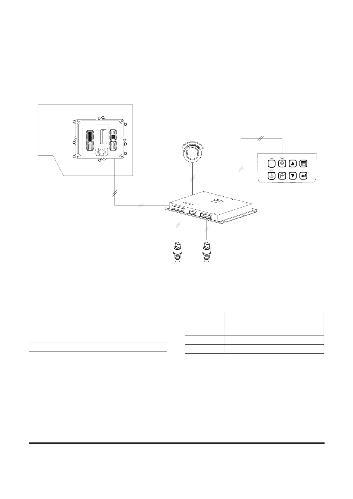
SP001038Electrical System
Page 70
AUTOMATIC DECELERATION
CONTROL (AUTO IDLE
CONTROL)
POWER
1
5
2
3
6
7
AUTO
4
ESC
8
E/G
FG000798
2
4
1
3
5 5
Figure 62
Reference
Number
Description
1 Instrument Panel
(Auto Idle Switch)
2 e-EPOS Controller
3 Engine Controller
4 Engine Control Dial
5 Pressure Switch
Reference
Number
Description
Page 73

SP001038
Page 71
Electrical System
If the machine is idling without the controls being operated or is
waiting for a dump truck the engine speed is automatically
lowered. Once the controls are operated and work is being
started the machine will be restored to the previous settings. As
a result, noise and fuel consumption will be reduced. This
function can be selected or cancelled through the Auto Idle
Selector Switch on the instrument panel.
The initial setting at start-up is with this switch in the select
position. Approximately 4 seconds after this function is selected,
if all work levers are in the neutral position, the e-EPOS
controller compares the automatic reduction signal with the
signal set by engine control dial. The lower of the two signals is
selected, the e-EPOS controller sends a signal to the engine
controller to control the engine speed.
The neutral status of the machine is detected by the two
pressure switches in the control valve. When the work levers are
in the neutral position, the switch is in the "OFF" position.
Page 74

SP001038Electrical System
Page 72
ENGINE OVERHEAT
PROTECTION SYSTEM
C
H
E
F
H
C
POWER
1
5
2
3
6
7
AUTO
4
ESC
8
E/G SPEED
02/05 [MO] 11:30
1700
RPM
CHECK
E/G
(E/G overheating signal)
(E/G overheating signal)
(Pump control signal)
FG000802
6 6
4 4
5
7
31
2
1
3
Figure 63
Reference
Number
Description
1 Instrument Panel
2 e-EPOS Controller
3 Engine Controller
4 Main Pump
5 Aux Pump
6 Control Valve
10 E.P.P.R. Valve (Electromagnetic
Proportional Pressure Reducing
Valve)
31 Warning Buzzer
Reference
Number
Description
Page 75

SP001038
Page 73
Electrical System
When the engine coolant temperature increases to over 107°C
(225°F), the engine controller detects it from the sensor
mounted in the coolant line and will send a signal to the e-EPOS
controller. The e-EPOS controller sends a overheat signal to the
instrument panel turning "ON" the warning light and buzzer
simultaneously.
Also, the e-EPOS controller returns an overheat signal to the
engine controller and changes power mode to standard mode.
The engine speed is then set to a low speed by the engine
controller.
When coolant temperature falls below 95°C (203°F), normal
operation will resume.
Page 76

SP001038Electrical System
Page 74
POWER BOOST MODE
Operation
C
H
E
F
H
C
POWER
1
5
2
3
6
7
AUTO
4
ESC
8
E/G SPEED
02/05 [MO] 11:30
1700
RPM
CHECK
P
O
W
ER
U
P
E/G
FG000800
6 6
16
4 4
5
2
20
18
1
11
3
Figure 64
Reference
Number
Description
1 Instrument Panel
2 e-EPOS Controller
3 Engine Controller
4 Main Pump
5 Aux Pump
6 Control Valve
11 Solenoid Valve (Boost)
16 Main Relief Valve
18
Breaker/Boost/Shear Selector
Switch
20
Power Boost Switch (Top of
Right Work Lever)
Reference
Number
Description
Page 77

SP001038
Page 75
Electrical System
The Power Boost function is used to temporarily increase the
main relief pressure to enhance excavation ability. When the
breaker/boost/shear selector switch is set to "BOOST" and the
power boost button on the center of the right-hand work lever
(joystick) is pressed during work, the e-EPOS controller will
activate the power boost solenoid valve and increase the relief
valve pressure from 330 - 350 kg/cm
2
(4,700 - 5,000 psi). The
excavation ability is increased by approximately 6%.
When the power boost function is in activated, a power boost
symbol appears on the information display department of
instrument panel.
NOTE: Do not use this switch for more than 10 seconds.
Page 78

SP001038Electrical System
Page 76
Power Boost Control - Circuit Diagram
(C4)
14
AMP 070 18P
(CN3)(CN4)(CN5)
12
6
AMP 040 12PAMP 070 16P
11 10 912
3 2 14
1516 14
6
78135
AMP 040 20P
133141516171820 19
10 6 5 4789
79 811 10
13 245
8 7 56
1718 1516
1112
2 1
CN1-8
CN1-9
CAN
CN7-6
CN4-6
CN2-2
CN1-11
(POWER MAX)
(POWER MAX / BREAKER)
CN6-10
CN6-9
CN7-5
CN7-4
CN4-5
CN4-4
CN6-2
CN6-1
CN1-1
CN1-2
15A
15A
AMP 040 28P
72 14 356 8
15
168 710 912 11
(CN7)
4 3 2 156
10111213 914
(CN6)
19
84910
3 2 1
1213
20
21
11 10 9
(CN2)
1
AMP MIC 21P
567 24 3
(CN1)
1517 1618 121314 11
(Center)
6123
14
11
6
15
16
13
PRESS
PST
SHEAR
TML
3
1 0
10
9
UP
BREAKER
2
20A
FG000586
1
2
26
26
11
18
26
25
24
20
Figure 65
Reference
Number
Description
1 Instrument Panel
2 e-EPOS Controller
11 Solenoid Valve (Pressure Up)
18 Breaker/Boost/Shear Selector
Switch
20 Power Boost Switch (Top of
Right Work Lever)
24 Battery
25 Battery Relay
26 Fuse
Reference
Number
Description
Page 79

Electrical System
SP001038
Page 77
Page 80

SP001038Electrical System
Page 78
AUTOMATIC TRAVEL SPEED
CONTROL
E/G
FG000799
6 6
7
8
4 4
5
13
15
17 2 19
3
Figure 66
Reference
Number
Description
2 e-EPOS Controller
3 Engine Controller
4 Main Pump
5 Aux Pump
6 Control Valve
7 Pressure Switch (Py Port)
8 Pump Pressure Sensor
13 Solenoid Valve (High speed)
15 Travel Motor
17 Engine Control Dial
19
Selector Switch For Automatic
Travel
Reference
Number
Description
Page 81

SP001038
Page 79
Electrical System
If the automatic travel speed control switch is set to the "OFF"
position, the travel motor will run in the I-speed (low speed)
range. If the selector switch is set to the "I" position, the travel
motor will run in the II-speed (high speed) range. If the selector
switch is set to the "II" position, the e-EPOS controller will
monitor the main pump discharge pressure and automatically
select the "ON" - "OFF" status of the II - speed travel solenoid
valve based on the travel load. The travel speed is changed
between the I-speed and the II-speed mode.
The travel load is monitored by the two pressure sensors in the
discharge lines of the front (upper) and rear (lower) pumps.
When the travel load is high (pressure over 300 kg/cm
2
(4,300
psi) the solenoid valve is turned "OFF" and I-speed (low) is
selected. In the case when the travel load is low (pressure under
160 kg/cm2 (2,280 psi), the solenoid valve will be turned "ON"
and the II-speed will be selected. But, if the engine speed control
switch dial is set below approximately 1400 rpm, the travel
speed will be set to I-speed mode.
Page 82

SP001038Electrical System
Page 80
Automatic Travel Speed Control - Circuit
Diagram
AMP 040 20P
17
1112
3
4
1516 14
6
78
13
5
(CN5)
1820 19
10 89
79 811 1012
10 9
(CN4)
6
2 1
13 245
AMP 070 16P AMP 040 12P
CN1-8
CN1-9
SIG
+
SIG
-
-
CN3-3
CN3-2
CN3-4
+
CN3-1
1568 7 24 3
4
910
3 2 1
8 7 56
AMP 040 28P
(CN7)
24 356
810 912 11
1718
111213141516
(CN3)
236 5 4 17
1213 11 10 915 1416
(CN2)
4 3 2 157 61 8
10111213 91415
(CN6)
167
(CN1)
1517 1619 18 13142021 12 11
3
CN3-17
GND
HIGH
AMP 070 18P
CN3-16
SIG
+(5V)
CN3-15
CW
2
1
LOW
AMP MIC 21P
8
5
2
CN2-5
CN2-4
7
6
II
I
II
0
0
I
3
CN1-12
(C3)
CN1-1
CN1-2
15A
15A
15A
8
9
2
26
26 26
25
24
19
17
13
FG000587
Figure 67
Reference
Number
Description
2 e-EPOS Controller
8 Pressure Sensor (Front Pump)
9 Pressure Sensor (Rear Pump)
13 Solenoid Valve (High speed)
17 Engine Control Dial
19
Selector Switch For Automatic
Travel
24 Battery
25 Battery Relay
26 Fuse
Reference
Number
Description
Page 83

SP001038
Page 81
Electrical System
SELF-DIAGNOSTIC FUNCTION
e-EPOS Controller
The system operation status and malfunction codes can be
checked through the display on top of the e-EPOS controller box
the rear cover behind the operator's seat.
1. Power Monitor
This LED is turned "OFF" when the input voltage to the
e-EPOS controller is below 18.5 ±1 V or above 32.5 ±1 V.
Stays "ON" while in normal range.
2. Engine Speed Monitor
This LED light flashes according to the engine speed. The
flashing interval is proportional to the engine speed.
1
2
4 3
FG000588
Figure 68
Reference
Number
Description
1 Upper Digit
2 Lower Digit
3
Engine Speed Monitor LED
(Flash Interval Increases With
Engine Speed.)
4
Power Monitor (Stays "ON"
While Power Is In Normal
Range,)
Reference
Number
Description
Page 84
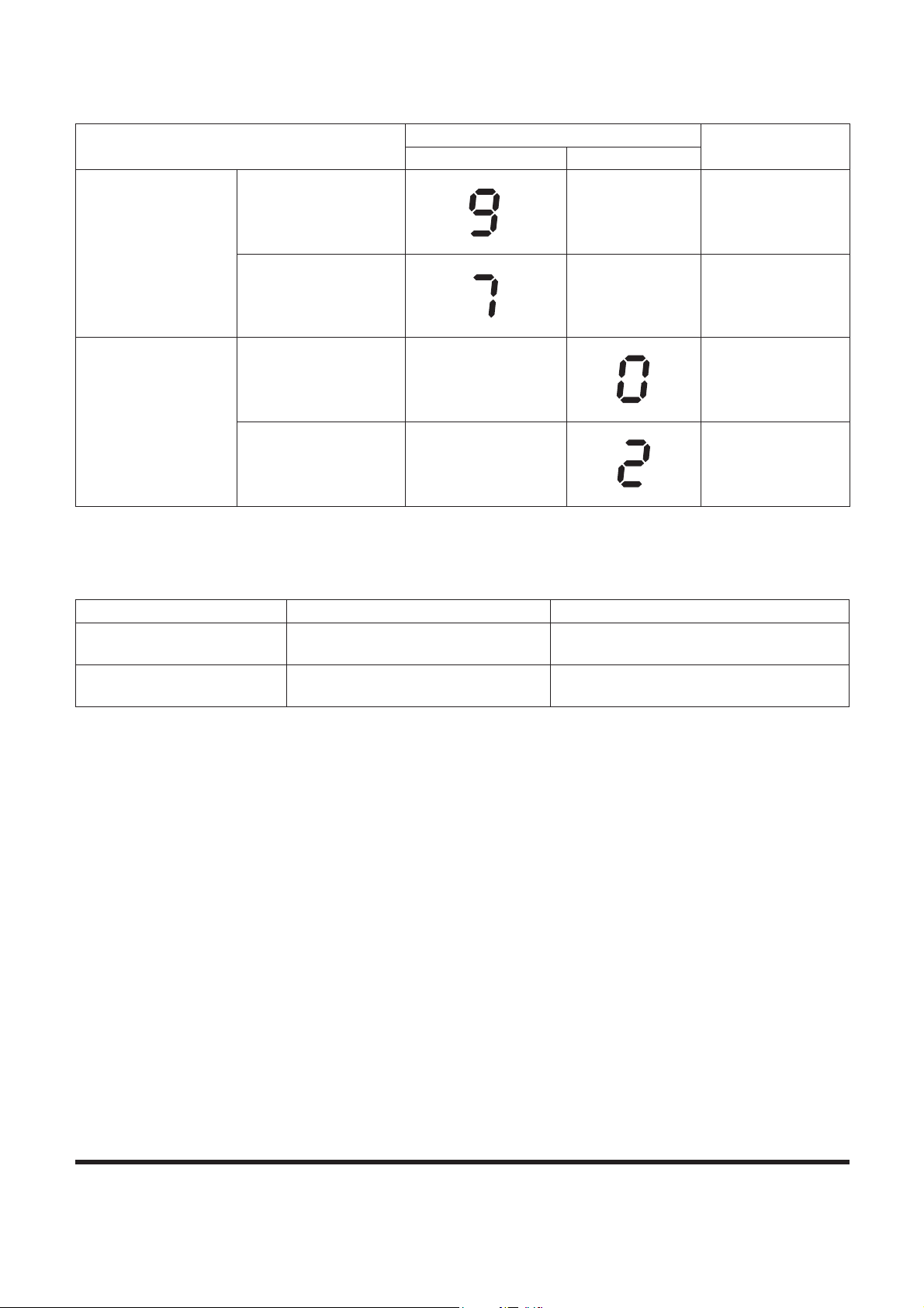
SP001038Electrical System
Page 82
3. Normal Operation Display Readout
4. Communication Monitor
What are shown in the 7-SEGMENT LED are same as
those in the Error Codes.
Mode Selection
Display Readout
Operation Status
Upper Digit Lower Digit
Power Mode
Power Mode
Normal Operation
Power Mode
Standard Mode
Normal Operation
Standard Mode
Work Mode
Digging
Normal Operation
Digging Mode
Trenching
Normal Operation
Trenching Mode
HAOH340L
HAOH350L
HAOH370L
HAOH380L
Error Code Indication Code Fault Location
V201 01 Communication error in instrument
panel.
V202 02 Communication error in engine
controller.
Page 85
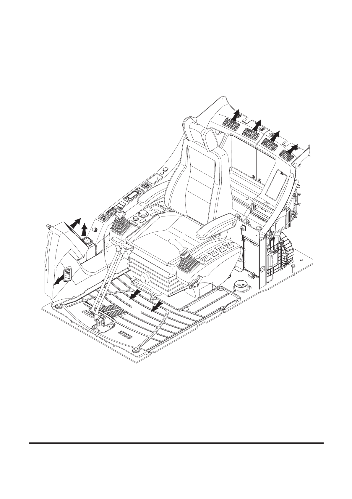
SP001038
Page 83
Electrical System
AIR CONDITIONER SYSTEM
Outline
Solid-type heater and air conditioner are installed in the cover
behind the operator's seat.
Temperature of the operator's room is adjusted automatically to
the temperature set by operator.
FG000784
A
A
C
B
C
Figure 69
Page 86

SP001038Electrical System
Page 84
(Please refer to the Operation Manual for detailed full automatic
control.
Vent mode selects the direction of discharged air.
Outlets by vent modes
Internal and External Filters
Internal and external air purification filters are installed for the
operator's room.
Filters should be cleaned every 500 hours.
If machine operates in an excessively contaminated
environment, filters should be cleaned more frequently and if
necessary, replaced with new ones.
How to Check Internal Air Filter
1. Press both levers on the left and right side at the top of the
filter installed at the rear of the operator's seat.
How to Check External Air Filter
1. Open the door at the left side of machine and loosen four
marked bolts to remove the cover (1, Figure 71).
Modes
Outlets A A+B B B+C C
FG000422
Figure 70
TOP
Donaldson.
FG000440
1
Figure 71
Page 87
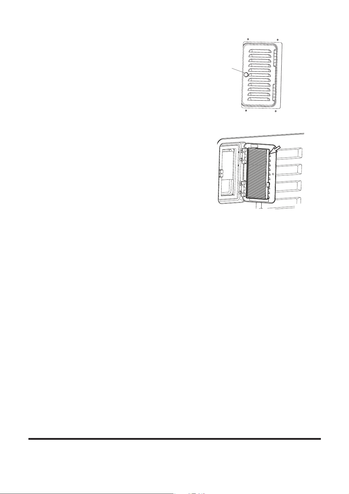
SP001038
Page 85
Electrical System
2. Turn marked knobs (1, Figure 72) at the rear side of the
cabin to open the cover.
3. Remove the filter attached to the cover and clean the
contaminated filter using compressed air.
4. Close the cover, replace the knobs, and secure the cover
to the support with butterfly bolts.
FG000441
1
Figure 72
FG000342
Figure 73
Page 88

SP001038Electrical System
Page 86
Air-Conditioning System Layout
11
1
2
3
5
7
5
4
9
8
6
6
10
FG007144
Figure 74
Reference
Number
Description
1 Air Conditioner/heater Unit
2 Condenser
3 Compressor
4 Receiver Dryer
5 Discharge Hose
6 Suction Hose
7 Liquid Hose (1)
8 Liquid Hose (2)
9 Ambient Temperature Sensor
10 Sun Sensor
11 Control Panel
Reference
Number
Description
Page 89

SP001038
Page 87
Electrical System
Air Conditioner/heater Circuit Diagram
44B44A
45B45A
49A
114C
142B
142A
48A
167B
49B
48B
116A
167C
115A
112A
114A
113A
99
116B
167A
115B
112B
114B
113B
47B
47A
43A
111A
110A
109A
108A
107B
106B
43B
111B
110B
109B
108B
107A
99
106A
46A
105B
168B
42E
42B
54E
130C
105A
168A
46B
42D
42C
47C
MODE F/BACK
CN9-17
0.5YW
CN10-10
(CN11)
4 3
KET 4P
2 1
(CN10)
141920 18 17 16 15 101113 12
18
AMP 040-III 20P
89 7 6 2 15 4 3
8
(CN8)
AMP 070 12P
(CN9)
1517 16 1214 13 911 10 12 11 10
AMP 070 18P
6 57 4 13 2 5 4
6789
123
CN8-1
0.5LgR
CN10-14
AMP 18P + 12P
CN8 CN9
CN8-4
0.85YG
0.5YR
SUN LOAD SENSOR
0.5Lg
CN8-3
-2 1+
CN8-5
0.5LY
SENSOR
AMBIENT TEMP
2
0.85BL
0.85YG
1
SENSOR
CN10
AMP 20P
2
CN10-17 1
INCAR
CN11
KET 4P
WATER
SENSOR
CN10-19
CN8-2
0.5OrB
CN9-2
CN9-4
1.25BL
0.5YW
CN9-1
0.5LgW
CN9-3
CN9-18
0.5LgB
0.5YR
CN9-10
1.25B
ACTUATOR
CN10-15
MIX F/BACK
GND
CN10-4
CN10-9
DUCT
SENSOR
WARM (P1)
Vref MIX
COOL (P2)
CN10-7
CN10-3
M
Temp. Control
0.85LW
CN10-1
CN10-2
CN10-20
CN10-12
CN11-1
CN10-11
CN10-13
CN9-16
CN9-14
0.5YB
0.5OrW
CN9-15
CN9-12
0.5OrR
0.5GrY
CN9-13
CN8-12
0.5GrG
0.5LW
CN8-11
1.25B
0.5LY
INTAKE
Vref MODE
VENT (P2)
REC (P2)
DEF (P1)
MODE
ACTUATOR
M
ACTUATOR
M
FRE (P1)
BLOWER
CN10-6
M
+
FET
0.85B
0.85BW
A/C THERMO (LOW)
CN9-8
CN8-10
0.5LB
0.5LG
0.85LR
RECEIVER DRIER
ILL
LED 1~12
A/C CONTROL PANEL
0.5WR
1.25LR
CN9-5
CN9-11
0.85LR
CN9-6
1.25LR
CN10-5
CN10-16
BLOWER
RELAY
CN11-4
A/C
RELAY
AIRCON UNIT
CN10-18
CN10-8
CN11-2
DIODE 4
0.85B
COMPRESSOR
24V
BATT.
FUSIBLE LINK
LAMP SWITCH
0.5RW
BATTERY RELAY
20A
STARTER SWITCH
FG001463
Figure 75
Page 90

Air Conditioner/heater Unit
Air Flow Diagram
External Air Inlet
Vent
Front
Outlet
VENT
Vent Rear
Outlet
Cold Box
Outlet
DEF
Outlet
Internal Air Inlet
Foot
Outlet
External Air
Figure 76
Page 88
DEF
FOOT
COOL
WARM
DOOR
-MIX
Heater
Core
DOOR
-INTAKE
Internal Air
Evaporator Fan
FG001359
SP001038Electrical System
Page 91

SP001038
Page 89
Electrical System
Door Open by Vent Modes
Main Components
Door
Mode
Vent Bi-level Foot Def/foot Def
Vent 100 60 0 0 0
Foot 0 40 100 80 60
Def 0 0 0 20 40
FG007754
Actuator
- Temp
Control
A/C
Relay
Duct
Sensor
Blower
Relay
Air Flow
Control
Module
Blower
Motor
Actuator
- Internal/external
Air Exchanger
Internal
Air Sensor
Internal
Air Filter
Evaporator
Water Temp
Sensor
Actuator
-Wind Direction
Control
Figure 77
Page 92

Actuator - Wind Direction Control
Change of discharged air flow according to selected wind
direction mode
Change of wind direction: Direction changes in the order of
VENTo BI-LEVEL o FOOT o FOOT/DEF o VENT.
Actuator - Temperature Control
Change of discharged air temperature by controlling the position
of temperature control door.
Figure 78
Actuator - Wind Direction Control
Wind Direction Mode Output Terminal Voltage
Vent
Bi-level 1.3 ± 0.2V
c(+): CN10-10
0.5 ± 0.2V
Foot 2.45 ± 0.2V
Foot/def 3.5 ± 0.2V
b(-): CN10-4
Def 4.5 ± 0.2V
Actuator - Temperature Control
Set Temperature Output Terminal Voltage
Max cooling c(+): CN10-9
Max heating Above 4.5V
b(-): CN10-4
Below 0.4V
FG001361
Page 90
SP001038Electrical System
Page 93

Actuator - Internal/external Air Exchange
CN10-20 CN10-2
FG001055
Figure 79
Mode Output Terminal Output
Intake P1(+), P2(-)
Moving of exchange door
by selecting intake.
Recirculate P1(-), P2(+)
Moving of exchange door
by selecting recirculate.
Air Flow Control Module
Air flow is controlled through the control of voltage between
GATE and SOURCE.
DRAIN
(CN10-1)
SOURCE
(CN11-1)
Figure 80
Air flow Output Terminal Output
1st
10 ± 0.5V
2nd 12.5 ± 0.5V
3rd 15 ± 0.5V
4th 17.5 ± 0.5V
CN11-2 CN10-1
5th 20.0 ± 0.5V
6th 22.0 ± 0.5V
7th More than 25V
GATE
(CN10-6)
FG001056
Input voltage is 27.5V.
The air flow is based on manual set.
Electrical System
SP001038
Page 91
Page 94

Relay - Blower: Power is supplied to the blower motor when the
system is turned "ON."
Specifications
Rated voltage 24V
Rated current 20A
Relay - A/C: Power is supplied to the magnetic clutch of the
compressor.
Specifications
Rated voltage 24V
Rated current 10A
Figure 81
L S1
(+)
Duct Sensor: It is inserted in the core of the evaporator to
prevent freezing of the evaporator.
The sensor consist of negative characteristic thermistor that
resistant value increases and decreases when the temperature
rises and falls, respectively.
Temperature (°C) Resistance (K:)
0 11.36 ± 0.1
2 10.39 ± 0.2
2.5 10.17 ± 0.2
3 9.95 ± 0.2
3.5 9.73 ± 0.2
4 9.52 ± 0.2
5 9.12 ± 0.2
10 7.36 ± 0.15
25 4.02 ± 0.08
30 3.33 ± 0.07
Figure 82
Figure 83
B
S2
(-)
FG001058
Page 92
SP001038Electrical System
Page 95

Water Temperature Sensor: It senses the temperature of
Figure 85
Temperature (°C) Resistance (K:)
-15 218.2 ± 7.5
0 97.83 ± 0.9
15 47.12 ± 0.7
25 30.0 ± 0.36
35 19.60 ± 0.3
FG001064
Figure 86
Temperature (°C) Resistance (K:)
-10 163 ± 4.9
0 96.9 ± 2.9
10 59.4 ± 1.8
20 37.4 ± 1.1
25 30 ± 0.9
30 24.2 ± 0.7
coolant water in the heater core.
Temperature (°C) Resistance (K:)
-10 55.8 ± 1.7
0 32.9 ± 0.9
15 15.76 ± 0.5
25 10.0 ± 0.3
35 6.5 ± 0.2
Internal Air Temperature Sensor: Built in the internal air filter,
it senses the internal temperature.
Figure 84
Ambient Air Temperature Sensor
Built at the bottom of the cockpit, it senses the temperature of
external air.
Electrical System
SP001038
Page 93
Page 96

SP001038Electrical System
Page 94
Sun Sensor
Built beside the socket of spare power, it senses the quantity of
the sun radiation to optimize discharge temperature and air flow
as set by operator.
Control Panel
Appearance and Terminal Arrangement
Refer to "Air Conditioner and Heater" of operation manual.
83.7
76.2
67.7
58.8
46.6
36.0
21.4
1.0 2.0 3.0 4.0 5.0 6.0 7.0
LUX(x10,000)
OUTPUT VOLTAGE(mV)
FG001062
Figure 87
AUTO
AUTO
OFF
TEMP
A/C
A/C
MAX
OUTSIDE
SEL
MODE
FG001063
18
8
(CN8)
AMP 070 12P
(CN9)
1517 16 1214 13 911 10 12 11 10
AMP 070 18P
6 57 4 13 2 5 4
6789
123
Figure 88
Page 97
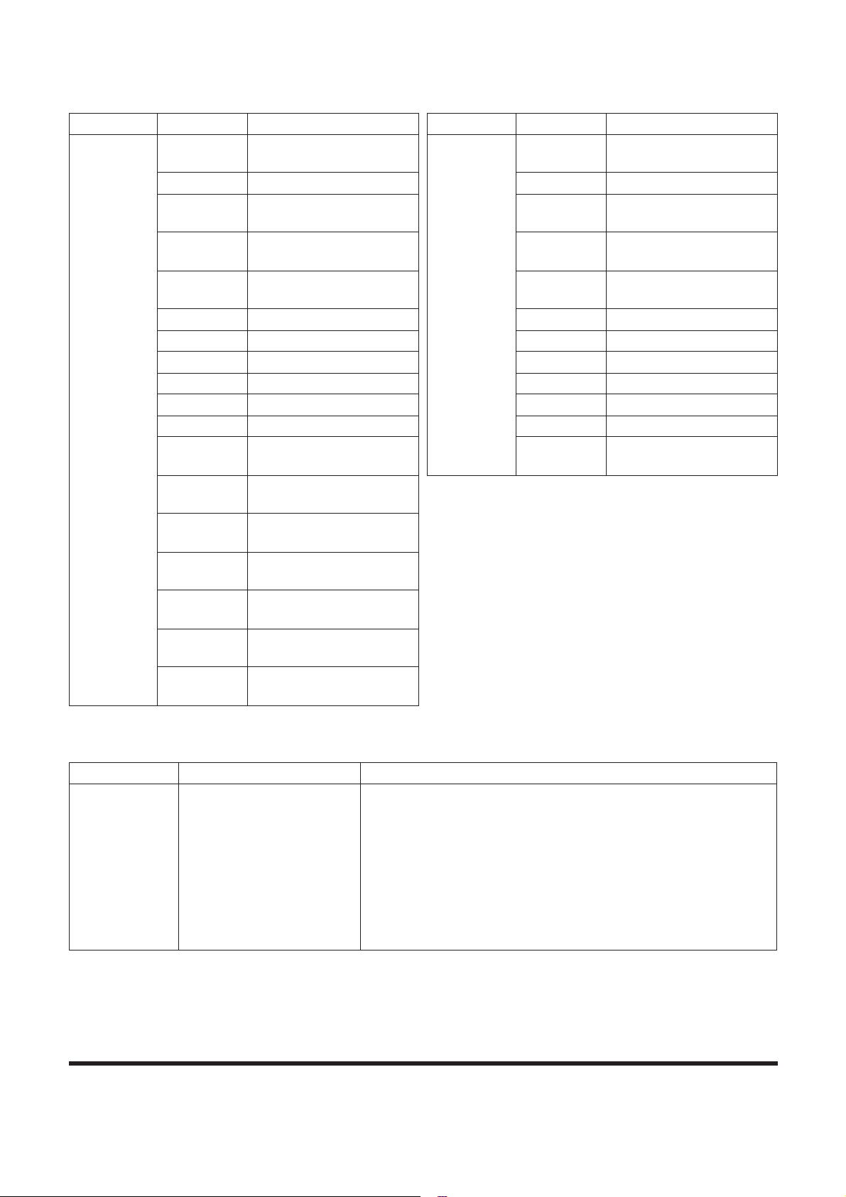
SP001038
Page 95
Electrical System
Terminal Terms
Control Logic
CN Term No. Terms CN Term No. Terms
CN9
1 Temperature control
(warm)
CN8
1 Water temperature
sensor
2 Sensor ground 2 Duct sensor
3 Temperature control
Power (5V)
3 Sun sensor
4 Mix feedback 4 Ambient air temperature
sensor
5 Power (KEY "ON") 5 Internal air temperature
sensor
6 Back-up 6 -
7 - 7 -
8 A/C output (LOW) 8 -
9 - 9 -
10 Ground 10 D.P.S CHECK
11 Illumination 11 Air flow module (gate)
12 Intake/Recirculate
(Recirculate)
12 Blower motor (feedback)
13 Intake/Recirculate
(Intake)
14 Wind direction control
(VENT)
15 Wind direction control
(DEF.)
16 Wind direction control
Power (5V)
17 Wind direction control
(feedback)
18 Temperature control
(cool)
Categories Inputs System Operation
AUTO Set temperature
Internal air temperature
sensor
Ambient air temperature
sensor
Water temperature sensor
Sun sensor
1. Automatically adjust room temperature as set and then
next items.
Temperature, Wind direction, Recirculate/Intake, Air flow,
Compressor
2. Auto mode is released when manually setting any switch
except, Temperature Control switch in Auto mode.
3. Upon the releasing of Auto mode, all of functions except
selected switch are controlled automatically.
Page 98
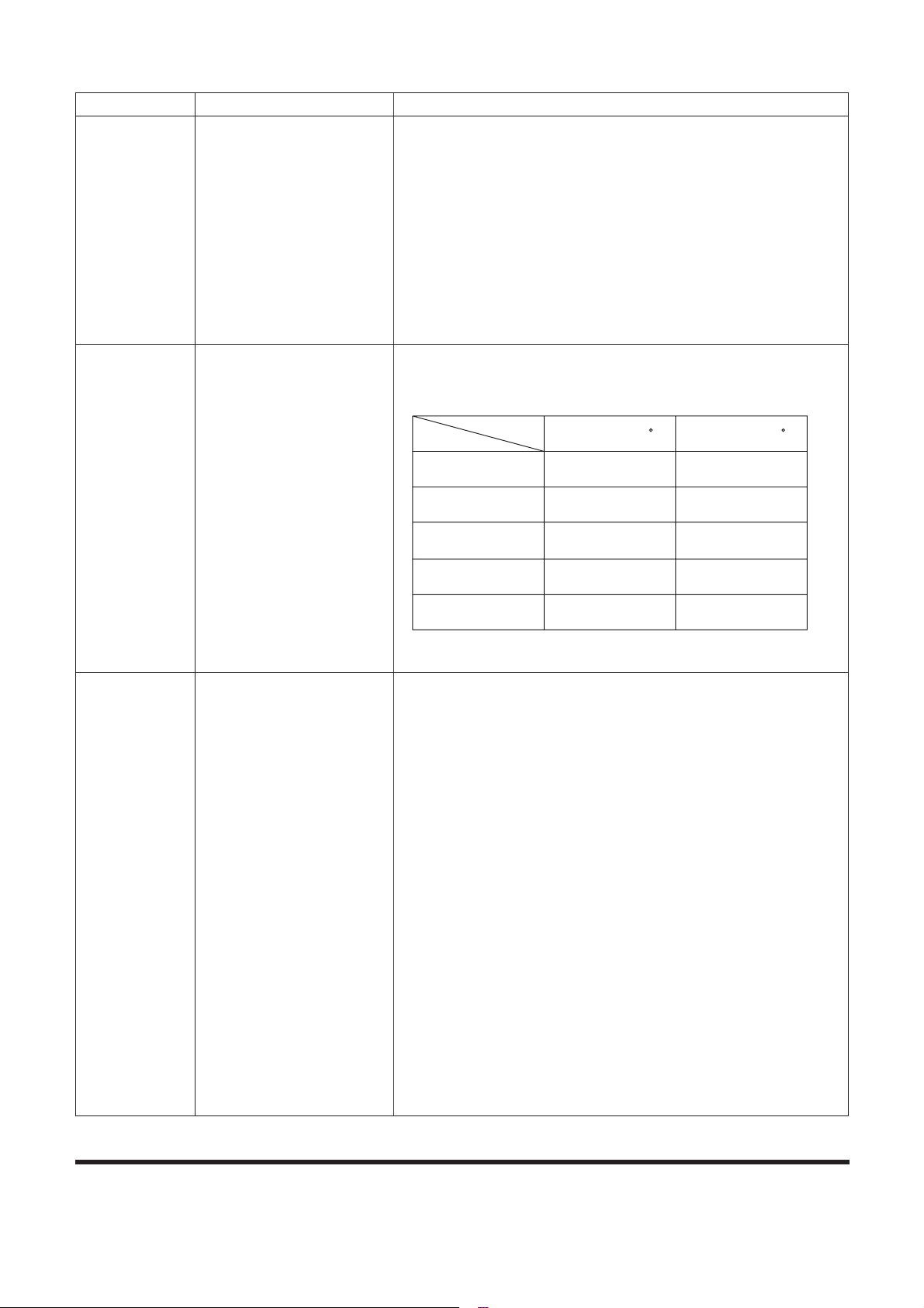
SP001038Electrical System
Page 96
Sensor
compensation
Set temperature
Internal air temperature
sensor
Ambient air temperature
sensor
Water temperature sensor
1. In case of sensor failure, following defaults are applied:
Internal air temperature sensor: 25°C, Ambient air
temperature sensor: 25°C, Duct sensor: -2°C
Temperature control actuator:
- Set Temperature 17 - 24.5°C: Max cooling, Set
Temperature 25 - 32°C: Max heating
Wind direction mode actuator
- VENT: VENT fix, modes other than VENT: Fixed to DEF
* Sun sensor is not compensated.
Max cooling/
heating control
Auto Setting 1. Set Temperature 32°C: Max heating
2. Set Temperature 17°C: Max cooling
* Max cooling/heating control is possible only in Auto mode.
Starting
Control of
Cooling
Auto mode
Duct sensor
1. Prevention of discharge of hot air before discharge
temperature drops enough in hot summer weather
2. Start conditions (AND condition)
(1) A/C on (AUTO or manual)
(2) Temperature sensed by the duct sensor is above 30°C
(3) Air flow: Auto mode
3. One time control in the cycle of engine OFF o engine run
4. Initial cooling control is executed when the Auto switch is
"ON" in the manual status (A/C "OFF" and manual control
of air flow) in 5 seconds after engine run.
5. Initial cooling control should be before max cooling.
6. Release condition (OR condition)
(1) A/C "OFF"
(2) Air flow: Manual control
(3) Release is possible with the "OFF" switch but not
allowed within 12 seconds (after Start "ON") while the
system is off using the "OFF" switch and during the time of
initial cooling control.
Categories Inputs System Operation
Temp Control
Actuator
Air Flow
Compressor
Intake/Recircle
Wind Direction Mode
Max Cooling (17 C) Max Heating (32 C)
FULL COOL FULL HOT
MAX HI AUTO HI
Forced ON OFF
Recircle Intake
VENT FOOT
Page 99

SP001038
Page 97
Electrical System
Starting
control of
heating (1)
Water temperature sensor
Internal air temperature
sensor
Auto mode
Set Temperature
1. Start condition (AND condition)
(1) When wind direction mode is one of the following
modes in the Auto or manual control mode
- BI-LEVEL, FOOT or FOOT/DEF
(2) The Water temperature sensor is stable and the water
temperature < 73°C
(3) Air flow: Auto mode
(4) Set temperature > Internal air temperature + 3°C
* Air flow falls gradually up to 12 seconds when operation
released.
2. One time control in the cycle of engine OFF o engine run
3. Initial heating control should be before max heating.
4. Air flow is controlled only when the wind direction is in the
manual mode and BI-LEVEL, FOOT, or FOOT/DEF is set.
5. Control through the water temperature sensor for start.
6. Starting control of heating (2) starts in case of fault of the
water temperature sensor during controlling.
7. Operation release (OR condition)
(1) Only air flow is released if it is selected manually.
(2) When handling the wind direction mode switch, only
wind direction is released but the air flow control is
performed only for the remaining period of the starting
control of heater.
(3) When Max Cooling (17°C) is selected.
(4) Water temperature sensor > 73°C.
Categories Inputs System Operation
Page 100

SP001038Electrical System
Page 98
Starting
control of
heating (2)
Water temperature sensor
Ambient air temperature
sensor
Internal air temperature
sensor
Auto mode
1. Entry condition (AND condition)
(1) Auto Mode
(2) Ambient air temperature < 5°C and difference between
ambient and internal air temperature d 5°C
(3) Failure of water temperature sensor
2. Only one time of engine OFF o engine run
3. Starting control of heating is before max heating.
4. Operation release (OR condition)
(1) Air flow: Manual selection
(2) When handling the wind direction mode switch, only
wind direction is released but the air flow control is
performed only for the remaining period of the starting
control of heater.
(3) Difference between internal and ambient air
temperature>15°C
(4) When Max Cooling (17°C) is selected.
5. Exceptional case
Starting control of heating is performed only once during
the remaining period if the entry condition is satisfied
within the starting control period that is the accumulation
of initial start times.
(Inclusive of Auto mode "ON" case within the period of
starting control of heater.)
* Air flow should be reduced slowly for up to 12 seconds in
case of exceptional entry case.
Categories Inputs System Operation
 Loading...