


Disassembly &
Assembly
Lift Trucks Power Train
D20S-3, D25S-3, D30S-3, D32S-3
D20S-3(B3.3), D25S-3(B3.3), D30S-3(B3.3),
D32S-3(B3.3), D33S-3(B3.3)
G20S-3, G25S-3, G30S-3
GC20S-3, GC25S-3, GC30S-3
G20E-3, G25E-3, G30E-3, G32E-3
GC20E-3, GC25E-3, GC30E-3, GC32E-3
G20P-3, G25P-3, G30P-3, G32P-3
GC20P-3, GC25P-3, GC30P-3, GC32P-3
SB2103E01
Jan.2004

Important Safety Information
Most accidents involving product operation, maintenance and repair are caused by failure to observe basic safety
rules or precautions. An accident can often be avoided by recognizing potentially hazardous situations before an
accident occurs. A person must be alert to potential hazards. This person should also ha v e the necessary
training, skills and tools to perform these functions properly.
Read and understand all safety precautions and warnings before operating or performing lubrication,
maintenance and repair on this product.
Basic safety precautions are listed in the “Safety” section of the Service or Technical Manual. Additional safety
precautions are listed in the “Safety” section of the owner/operation/maintenance publication.
Specific safety warnings for all these pub lications are pro vided in the description of operations where hazards
exist. W ARNING labels have also been put on the product to provide instructions and to identify specific hazards.
If these hazard warnings are not heeded, bodily injury or death could occur to you or other persons. W arnings in
this publication and on the product labels are identified by the f ollo wing symbol .
WARNING
Improper operation, lubrication, maintenance or repair of this product can be dangerous and could result
in injury or death.
Do not operate or perform any lubrication, maintenance or repair on this product, until you have read and
understood the operation, lubrication, maintenance and repair inf ormation.
Operations that may cause product damage are identified by NOTICE labels on the product and in this
publication.
DAEWOO cannot anticipate every possible circumstance that might involv e a potential hazard. The warnings in
this publication and on the product are therefore not all inclusiv e. If a tool, procedure, work method or operating
technique not specifically recommended by DAEWOO is used, you must satisfy yourself that it is safe for you and
others. Y ou should also ensure that the product will not be damaged or made unsafe by the operation, lubrication,
maintenance or repair procedures you choose.
The information, specifications, and illustration in this publication are on the basis of information available at the
time it was written. The specifications, torques, pressures, measurements, adjustments, illustrations, and other
items can change at any time. These changes can affect the service given to the product. Obtain the complete
and most current information before starting any job. DAEWOO dealers have the most current inf ormation
available.
1


Index
Transmission
Assembly Input Shaft ...............................................16
Assembly Output Shaft ............................................19
Assembly Reverse Shaft..........................................11
Assembly Transmission Housing .............................20
Disassembly / Assembly Valve Body .......................26
Disassembly Input Shaft ..........................................14
Disassembly Output Shaft........................................19
Disassembly Reverse Shaft .......................................9
Disassembly Transmission Housing ..........................5
Drive Axle
Adjustment Bevel Pinion ..........................................37
Adjustment Disassembly /
Assembly of Bevel Pinion.........................................39
Assembly Bevel Pinion.............................................39
Assembly Carrier Diff ...............................................45
Assembly Crown wheel/Adjustment .........................42
Assembly Shaft As ...................................................31
Disassembly / Assembly Brake Parts.......................32
Disassembly / Assembly Differential ........................40
Disassembly / Assembly Hub Drive Axle..................33
Disassembly / Differential Assembly ........................34
Disassembly Axle .....................................................27
Disassembly Bevel Pinion ........................................35
Disassembly Shaft As...............................................31
Special Service Tools ...............................................51
Disconnect batteries before performance of any
service work.
WARNING
Power Train Index
3

Disassembly
Transmission Housing
IDCD501P
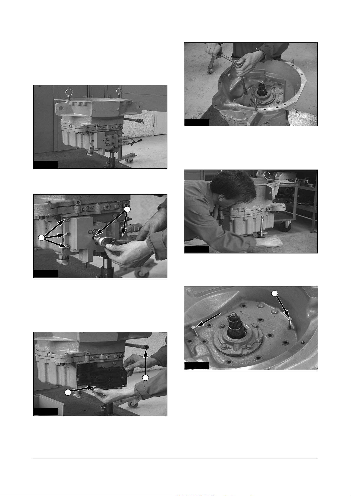
1. Mount the transmission on a suitable jig.
1
1
IDCD502P
2. Disconnect valve body, loosen the screws (1) with
socket head wrench 8 mm.
ATTENTION: Loosen bolts from outside to inwards!
IDCD504P
4. To remove the torque converter housing,
loosen the upper housing screws.
(Hexagonal socket 17 mm)
IDCD505P
5. Loosen the lower housing screws.
(Hexagonal socket 17 mm)
4
IDCD506P
3
6. Install 2 jackbolts (M10, 30mm (1.2in)) in locations
2
(4) until they stop against bearing plate,
alternately tighten bolts to separate the torque
converter housing from the transmission.
IDCD503P
3. Remove the Gasket (2) and oil dipstick (3).
Power Train Disassembly & Assembly
5
IDCD507P
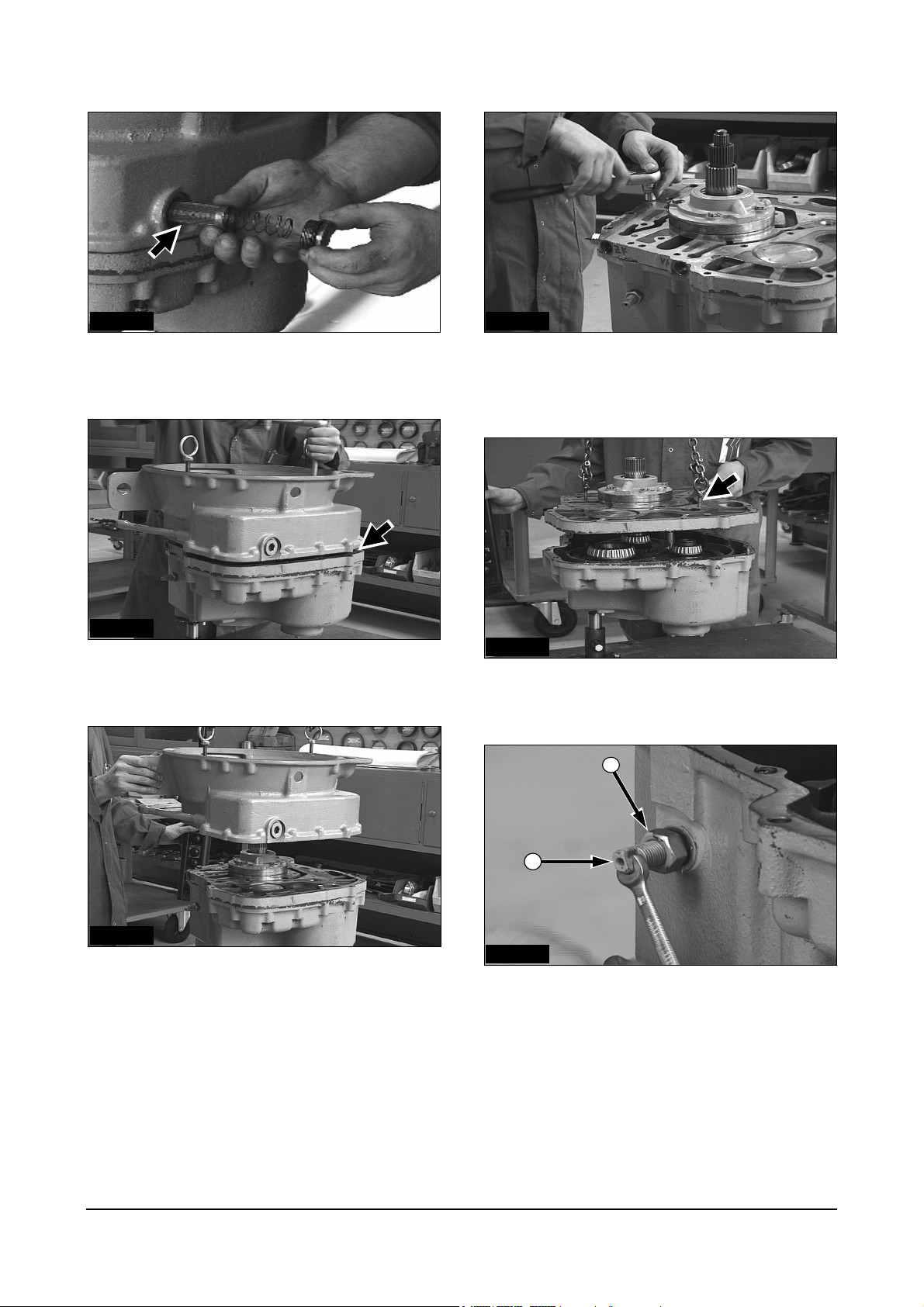
7. To remove strainer, loosen the screw with an allen
head wrench.
IDCD510P
10. Remove the remaining screws between the T/M
bearing plate and the torque converter housing.
(Hexagonal socket 17 mm).
IDCD508P
8. Lift the torque converter housing from the T/M
bearing plate.
IDCD509P
9. Secure the eyebolts M10 to remove the torque
converter housing.
IDCD511P
11. Secure the eyebolts M10 to remove the T/M
bearing plate.
1
2
IDCD512P
12. Loosen the jam nut (1) to loosen the hand brake
adjustment with the ring spanner (22 mm) and the
threaded bolt (2) with the open ended spanner (10
mm).
Power Train Disassembly & Assembly
6
1
13. Turn the adjustment bolt until the strut (1) can be
removed from the brake band.
IDCD516PIDCD513P
16. Remove the output shaft.
IDCD517P
IDCD514P
17. Remove the input shaft with forward clutch.
14. Remove the brake struts from the eccentric shaft.
IDCD518P
IDCD515P
15. Lower the loosened brake band into the housing.
Remove after dismounting the shaft.
18. Use the eyebolt M18 to lift the reverse shaft.
Power Train Disassembly & Assembly
7
IDCD592P
19. Remove the lube pump. (Hexagonal socket 13
mm)
IDCD593P
20. Lift the lube pump with 2 screw drivers.
Power Train Disassembly & Assembly
8
Disassembly
Reverse Shaft
1
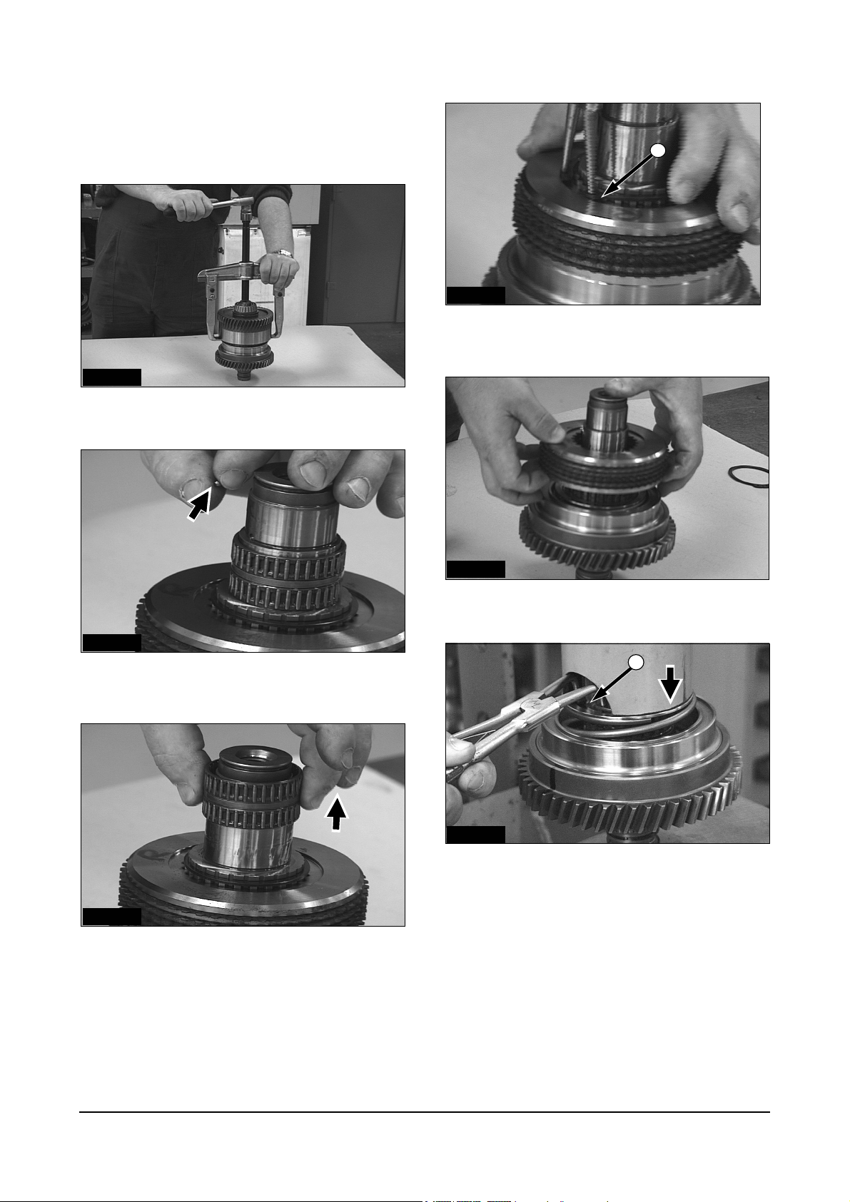
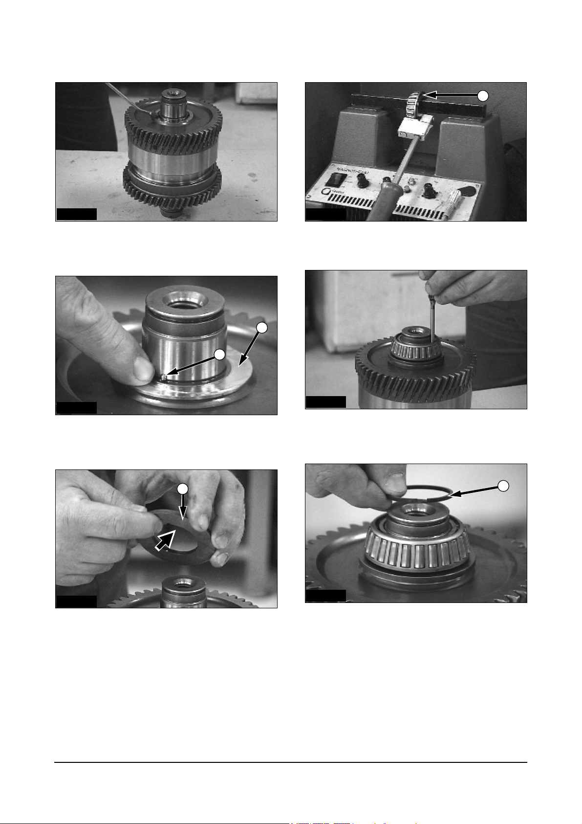
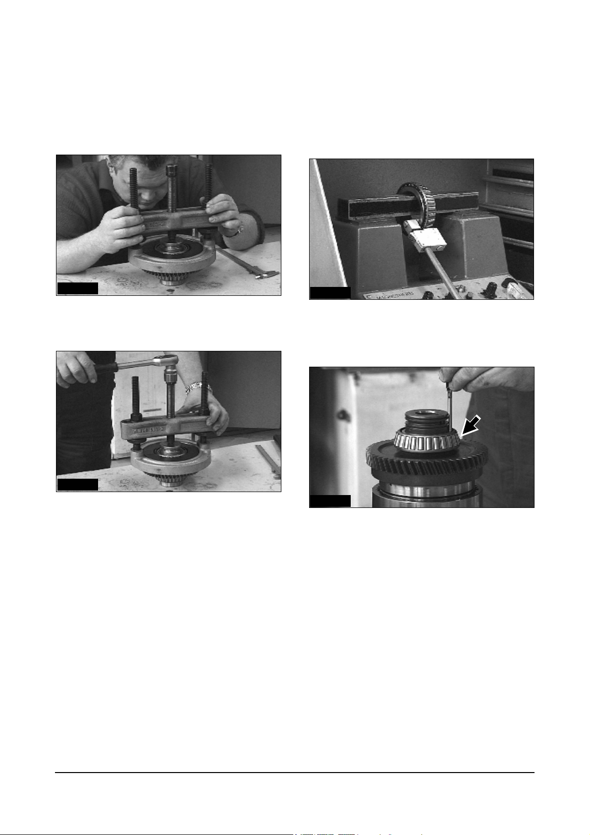
IDCD521P
1. Disassemble the shaft with the 2-leg puller.
IDCD522P
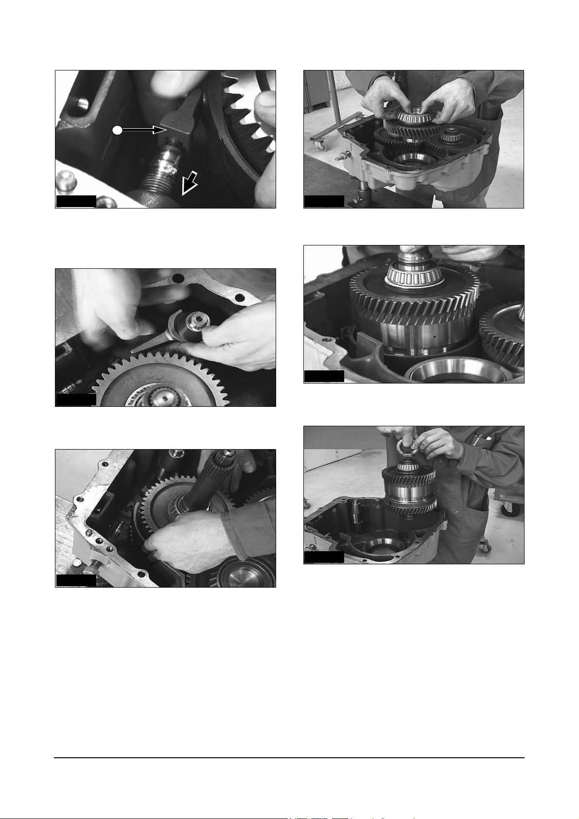
2. Remove the safety ball from the seat with a screw
driver.
IDCD524P
4. Remove the snap ring (1) from the support disk
with the circlip pliers.
IDCD525P
5. Lift the multiple disk body.
2
IDCD526P
6. Remove the snap ring (2) while pressing the
return spring on the spring retainer with a
IDCD523P
3. Remove the double needle bearing.
Power Train Disassembly & Assembly
9
hydraulic press. Slowly relieve the tension of the
spring. (Tool Ref. No 1)
1
2
3
IDCD527P IDCD530P
7. Remove the parts - snap ring (1), spring
retainer(2) and return spring (3)
10. ATTENTION: Open the R-rings before lifting!
IDCD531P
IDCD528P
8. Lift the piston by using compressed air in the
lower bore.
11. Remove the bearing from the shaft with a 2-leg
puller.
4
IDCD529P
9. Remove both R-rings before lifting the bearing (4).
Power Train Disassembly & Assembly
10
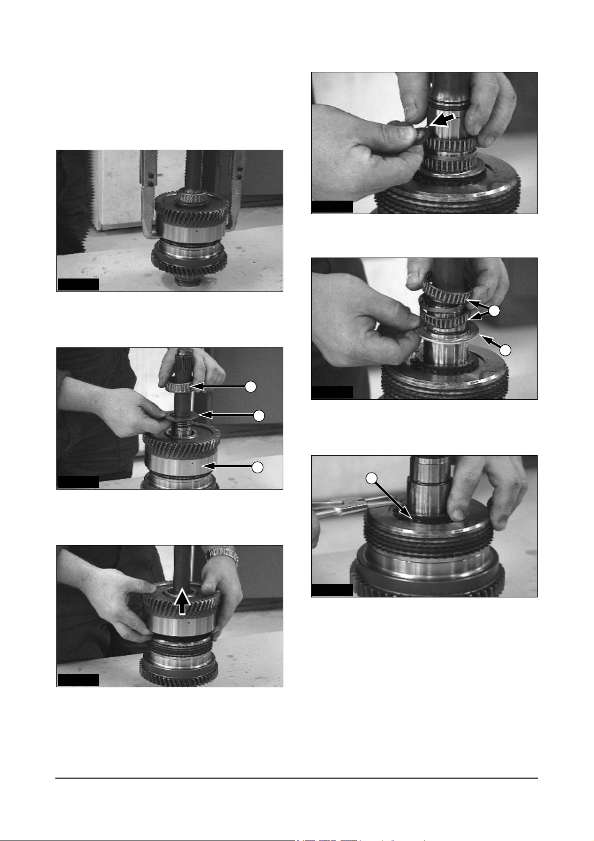
Assembly
Reverse Shaft
3
IDCD532P
12. Heat bearing (1) to a temperature of 120°C
(248°F) and install it on the shaft.
IDCD533P
13. After the bearing has cooled, the inner bearing
ring must be tapped into position.
IDCD535P
15. Inner and outer piston rings must be lubricated
with transmission oil.
IDCD536P
16. Insert the piston.
ATTENTION: Canting the piston can cause damage.
5
2
IDCD537P
IDCD534P
14. Install both R-rings (2) in their grooves.
Power Train Disassembly & Assembly
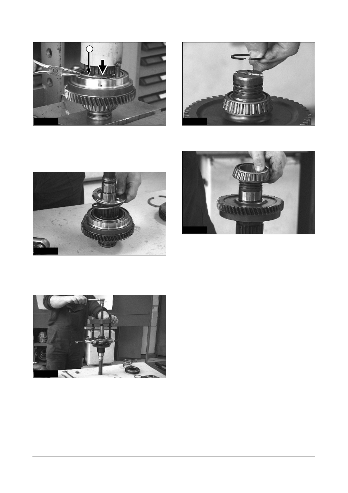
17. Install return spring (3), spring retainer (4) and
11
4
3
snap ring (5).
1
18. Install snap ring (1) by pressing the return spring.
(Tool Ref. No 1)
IDCD541PIDCD538P
21. Align the teeth of the clutch disks.
2
5
IDCD539P
3
4
19. Elements of the multiple disk body: (2) pressure
disk, (3) inner separater disks, (4) outer clutch
disks, (5) support disk
IDCD542P
22. Install the needle bearing.
IDCD543P
IDCD540P
20. Put the multiple disk body on the gear and install
the snap ring.
Power Train Disassembly & Assembly
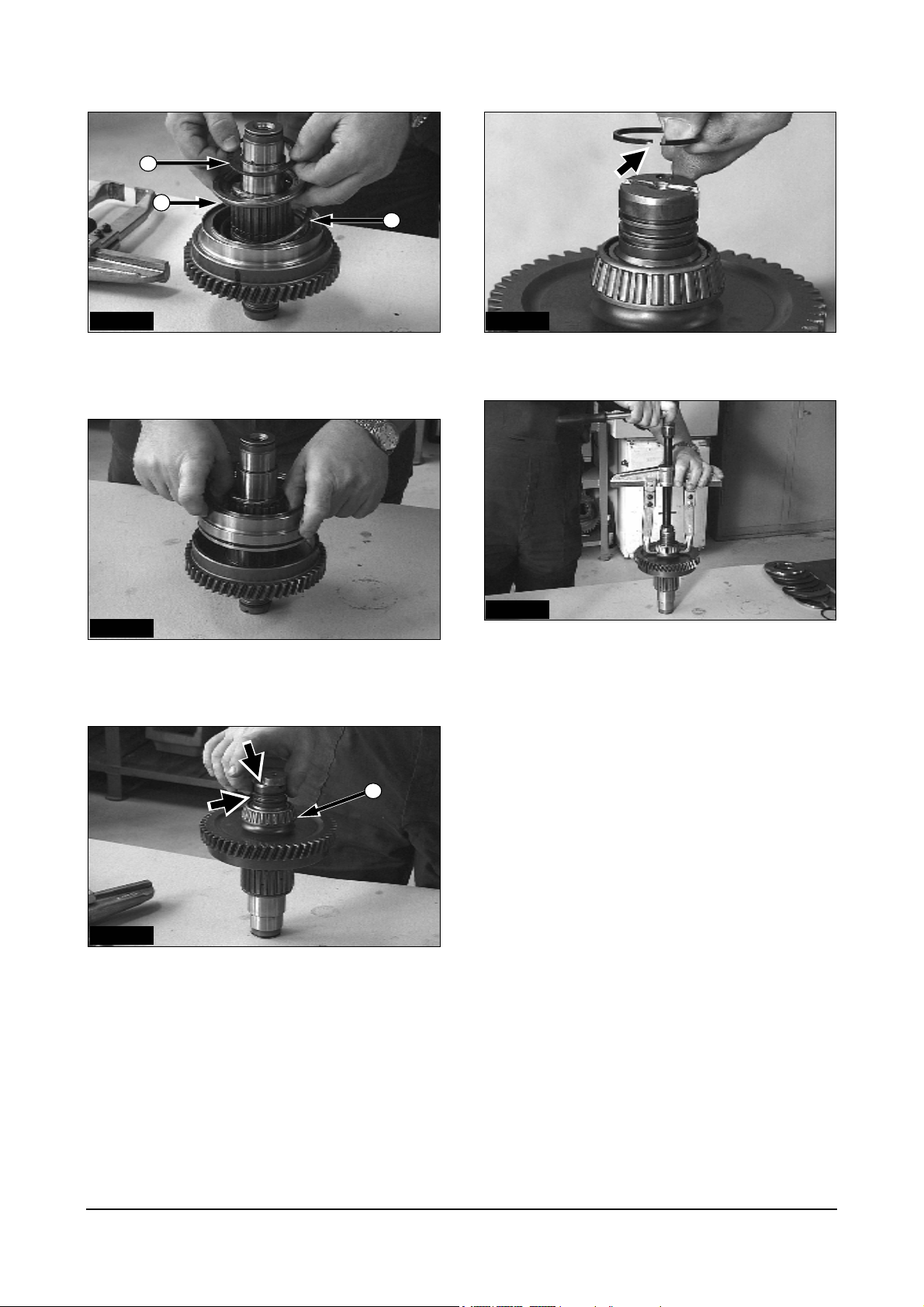
23. Put the gear wheel on the shaft.
12
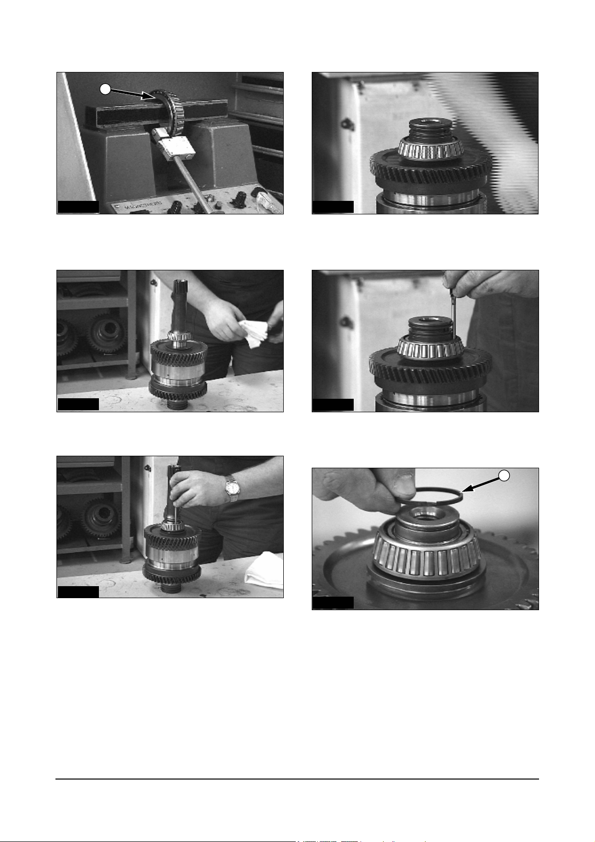
24. Lubricate the needle bearing before installing the
washer.
1
2
IDCD547PIDCD544P
27. Heat bearing (4) to a temperature of 120°C
(248°F) and install it on the shaft.
4
IDCD545P
25. After installing the washer (1), put the ball (2) in
the hole.
3
IDCD546P
26. Install the steel-washer (3).
ATTENTION: The ball must engage the notch!
IDCD548P
28. After cooling the bearing, the inner bearing ring
must be tapped to set bearing.
IDCD549P
29. Install the R-ring (5).
5
Power Train Disassembly & Assembly
13
Disassembly
Input Shaft
IDCD550P
1. Disassemble the shaft with a 2-leg puller.
Remove R-ring before lifting the bearing.
2
3
1
IDCD551P
2. After lifting the gear wheel (1), remove bearing (2)
and washer (3).
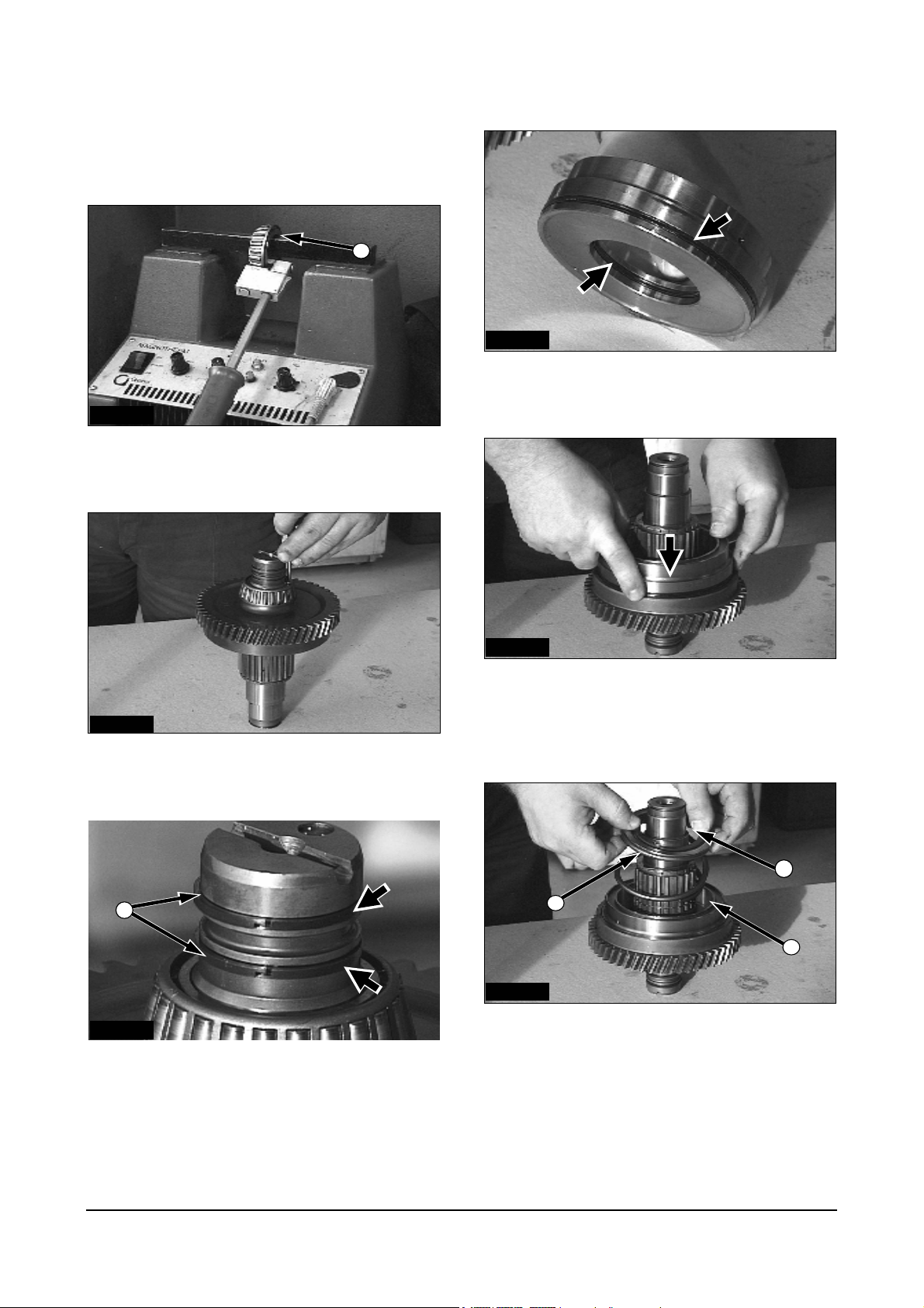
IDCD553P
4. Remove the ball from the seat with a magnet.
IDCD554P
5. Remove the double needle bearing (4) and the
brass washer (5).
6
4
5
IDCD555P
6. Remove the snap ring (6) from the support disk
with the circlip pliers and remove the disks.
IDCD552P
3. Lift the gear wheel.
Power Train Disassembly & Assembly
14
1
IDCD556P IDCD530P
7. Remove the snap ring (1) while pressing the
return spring on the spring retainer with a
10. ATTENTION : Open the R-rings before lifting.
hydraulic press. Slowly relieve the tension of the
spring. (Tool Ref. No 1)
IDCD559P
IDCD557P
11. Lift the back bearing.
8. Lift the piston by using compressed air in a lower
bore, after removing the spring retainer and return
spring.
IDCD558P
9. Remove both R-rings before lifting the bearing.
Power Train Disassembly & Assembly
15

Assembly
Input Shaft
1
IDCD560P
12. Ring (1) and inner needle bearing (2).
IDCD561P
13. Drive the ring and bearing with an puncher
(Ø25mm, length 400 mm) (Ø 1.0 in X 15.75 in
length) into the shaft.
2
IDCD563P
15. Insert the piston.
ATTENTION: Canting the piston can cause damage.
IDCD564P
16. Install snap ring by pressing the return spring.
(Tool Ref. No 1)
IDCD565P
17. Put the multiple disk body on the gear.
IDCD562P
14. Inner and outer piston rings must be lubricated
with the transmission oil.
Power Train Disassembly & Assembly
16

1
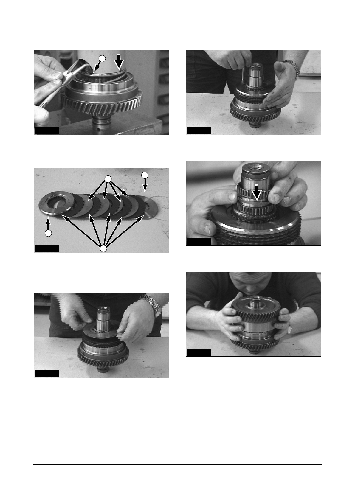
IDCD566P
18. Mount the snap ring (1) on the support disk with
the circlip pliers.
IDCD567P
19. Lubricate the support disk area.
IDCD569P
21. Align the teeth of the clutch disks and put gear
wheel on the shaft.
IDCD570P
22. Lubricate the washer.
IDCD571P
IDCD568P
20. Install the washer and needle bearings.
23. Put the ball in the hole of the shaft and the notch
in the washer.
ATTENTION: The ball must engage the notch!
Power Train Disassembly & Assembly
17
1
IDCD572P IDCD575P
24. Heat bearing (1) to a temperature of 120°C
(248°F) and install it on the shaft.
IDCD573P
25. Install the bearing on the shaft.
27. Install the heated back bearing (120°C, 248°C) on
the shaft.
IDCD576P
28. After mounting and cooling, the inner bearing ring
must be tapped into position.
2
IDCD574P
26. After the bearing has cooled, the inner bearing
ring must be tapped into position. Install the R-ring.
IDCD577P
29. Mount and hook the R-ring (2).
Power Train Disassembly & Assembly
18
Disassembly
Output Shaft
Assembly
Output Shaft
IDCD578P
1. ATTENTION: Set the puller on the inner bearing
ring!
IDCD579P
2. Remove the shaft with suitable puller device.
This can be done from either end of shaft.
IDCD580P
3. Heat bearing (1) to a temperature of 120°C
(248°F) and install it on the shaft.
IDCD581P
4. After cooling, the inner bearing ring must be
tapped into position.
Power Train Disassembly & Assembly
19
Assembly
Transmission Housing
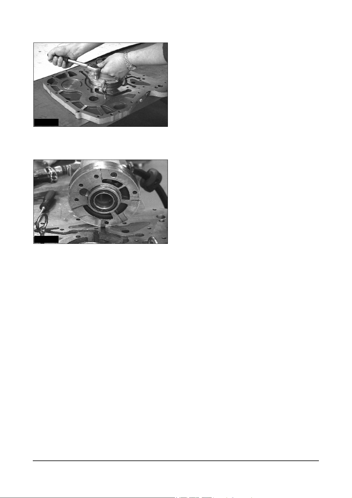
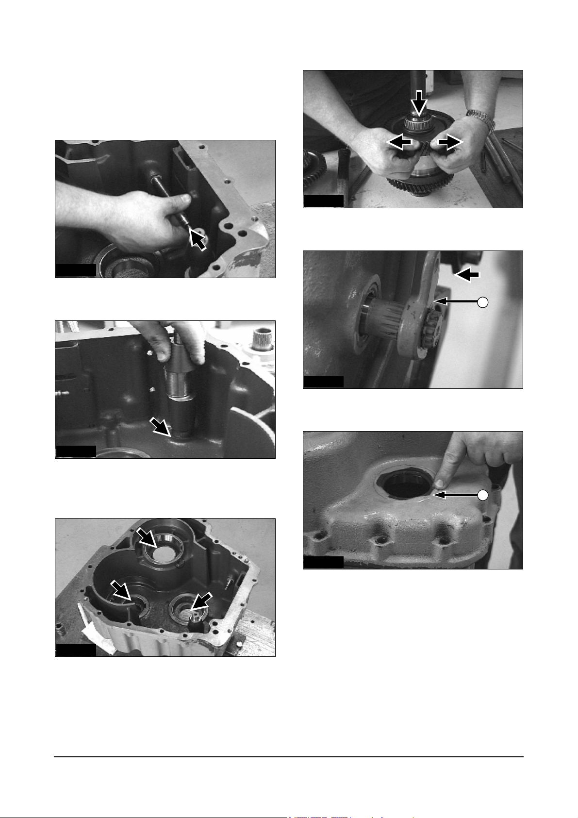
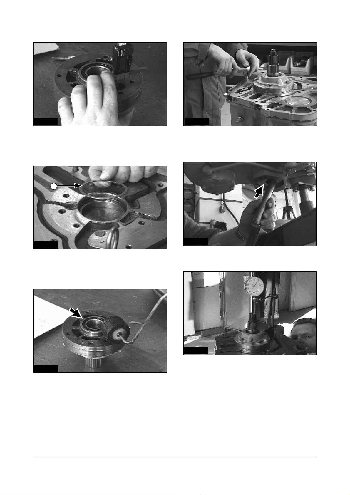
IDCD582P
1. Mount the parking brake adjustment bolt.
IDCD583P
2. Eccentric shaft for parking brake.
Check the free-movement.
IDCD585P
4. Mount the brake band.
IDCD586P
5. Mount the snap ring of the park brake lever (1).
1
2
IDCD587P
6. Oil Seal of output gear wheel (2) must be set flush
with the housing surface.
IDCD584P
3. Check the bearing parts for damages.
Be sure all surfaces are clean.
Power Train Disassembly & Assembly
20
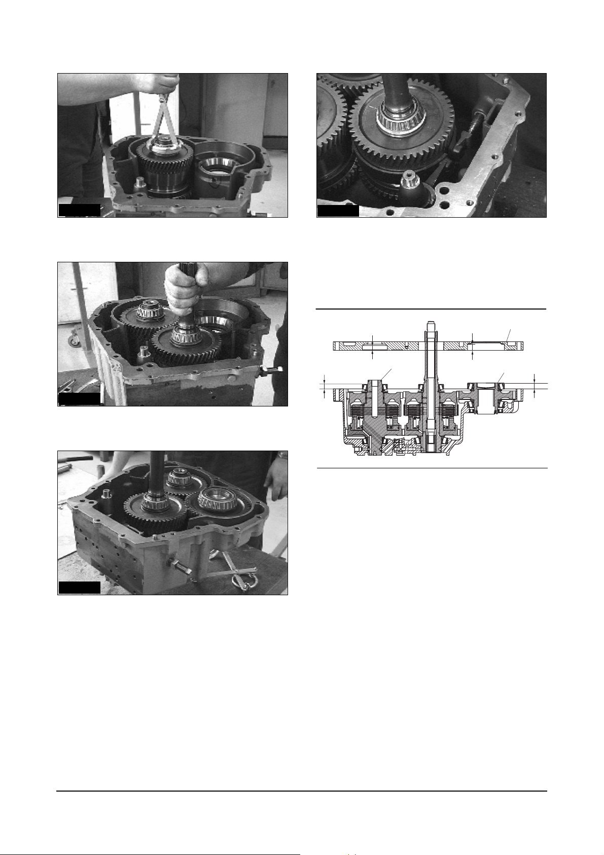
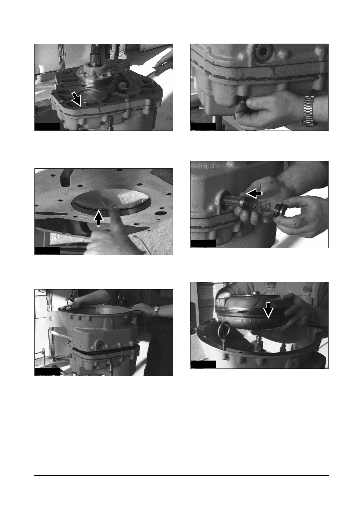
IDCD588P
7. Install the reverse shaft.
IDCD591P
10. Assemble the struts for the parking brake band.
Adjust after assembly.
11. Install each bearing cup on the reverse shaft
assembly and the output shaft assembly.
IDCD589P
8. Install the lnput shaft. Check for free rotation.
IDCD590P
9. Install output shaft last.
Check for free rotation.
A
B
Reverse
Shaft
B’
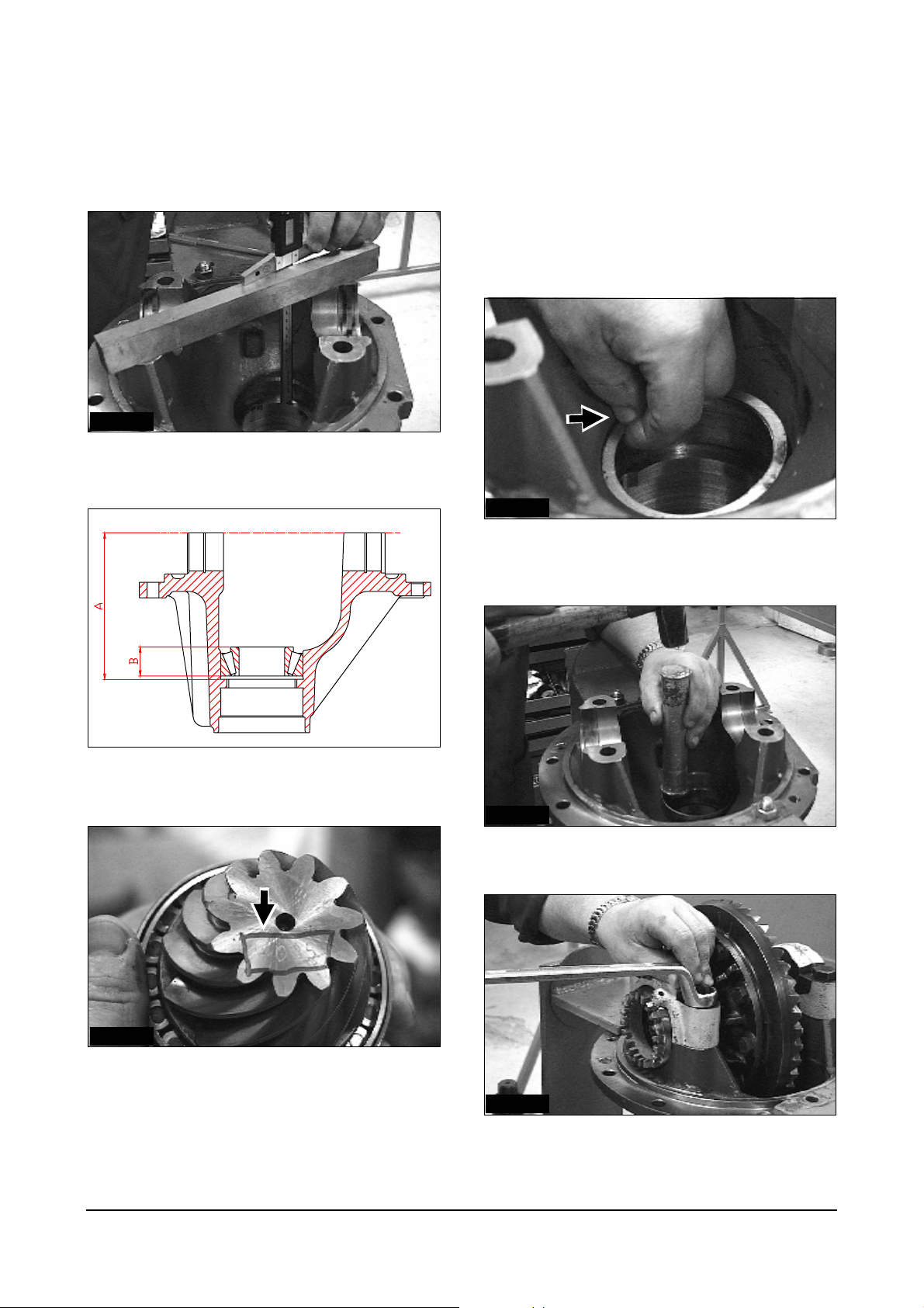
12. Measure the height from the surface of
transmission housing to the top of the each
bearing cup (A or A‘ dimension)
* To minimize the measuring error measure at
least three places and average them.
13. Measure the depth from the bearing plate surface
to the shoulder of the hole for the bearing of each
shaft, reverse and output (B or B’ dimension)
* For the output shaft, measurement should be
done with the cover installed
14. Caculate the required shimpack thickness (Z) with
the following formula.
Z = B-A+(0.05~0.08mm) or (0.002~0.003in)
For reverse shaft
= B’-A’+(0.05~0.08mm) or (0.002~0.003in)
For output shaft
15. Insert shims according to the calculated thickness
above behind the bearing cup of each shaft. And
assemble bearing cups into the bearing plate.
Bearing Plate
Output
Shaft
A’
Power Train Disassembly & Assembly
21
1
2
3
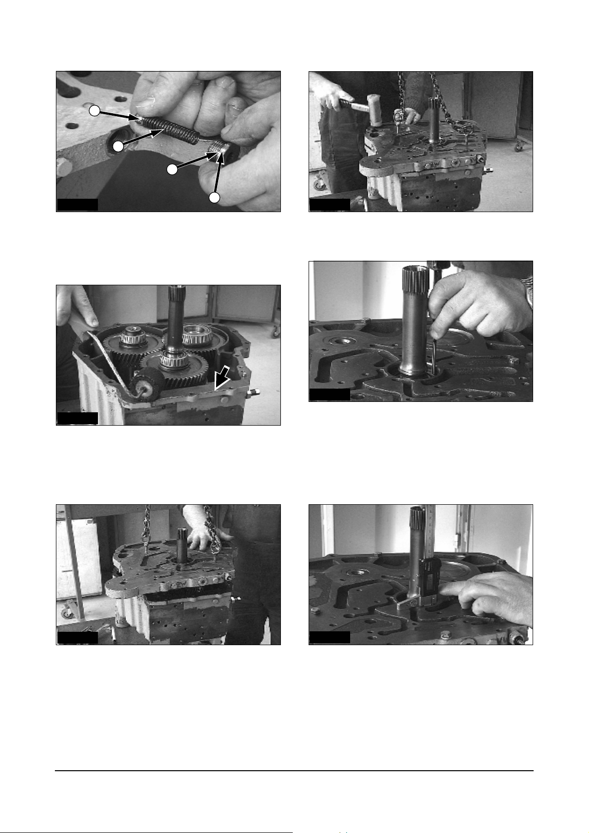
IDCD594P
4
16. Valves in the bearing plate consist of: ball(1),
spring(2), seal ring (3) and plug (4).
Tighten the plug with allen head wrench 6 mm.
IDCD595P
17. The housing areas must be cleaned and
degreased. Apply sealing compound (LOCTITE
17430) to coat on one side.
IDCD597P
19. Tap the bearing plate into position over dowel pins
and tighten all bearing plate mounting bolts.
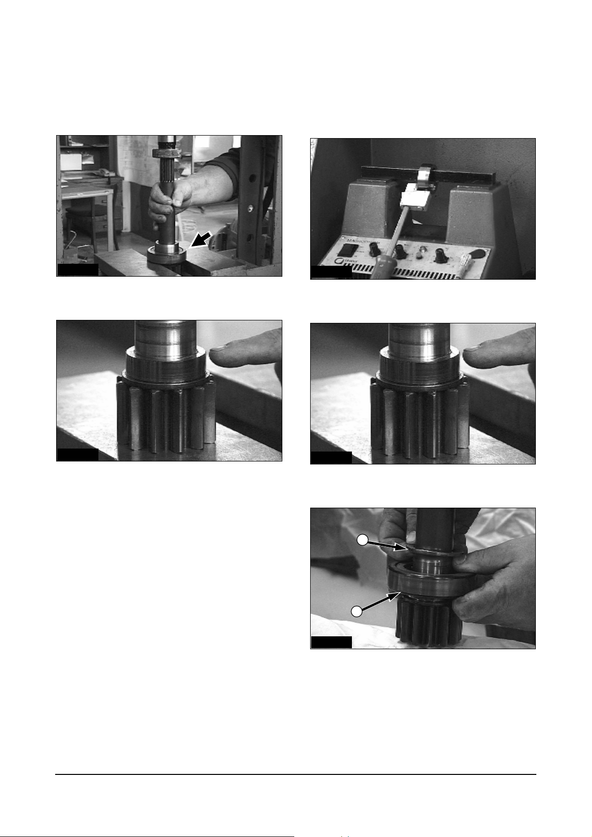
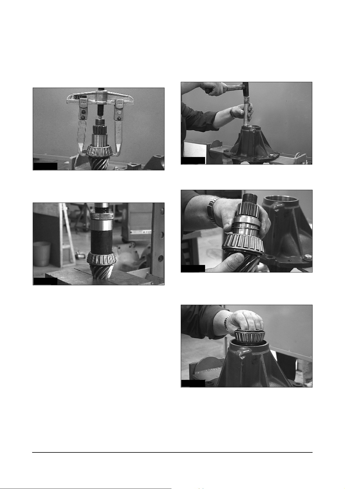
IDCD598P
20. Using a punch, tap bearing cone down against
input shaft. Install bearing cup against cone in the
same manner.
ATTENTION: Check for free rotation.
IDCD596P
18. Lower the bearing plate.
IDCD599P
21. Measure the depth of the bearing cup below
bearing plate surface at three places.
Average this dimension and record as Dim. A
Power Train Disassembly & Assembly
22
IDCD600P
22. Measure the height of pump pilot surface above
mounting surface at three places.
Average this dimention and record as Dim. B.
1
IDCD510P
25. Assemble the lube pump with screws M8, torque
32 ± 3 N·m (23.5 ± 2.0 lb·ft) (Hexagonal socket 13
mm).
IDCD601P
23. Select shim thickness by subtracting B Dim. from
A Dim. Shim thickness = A-B+0.0-0.05mm (+0.0-
0.002 in)
IDCD602P
24. The sealing area of the lube pump must be
cleaned and degreased. Apply sealing compound
(LOCTITE 17430) to pump flange.
IDCD604P
26. Tap the outer front bearing ring back.
IDCD605P
27. Check the shaft end play by moving the shaft up
and down.
Dial indicator should not exceed 0.05mm
(0.002 in)
Power Train Disassembly & Assembly
23
IDCD606P IDCD609P
28. The housing areas must be cleaned and
degreased. Apply sealing compound (LOCTITE
17430) on one side of bearing plate.
31. Install the housing screws with a torque of
55 ± 5 N·m (41 ± 4 lb·ft).
IDCD610P
IDCD607P
29. Before joining torque converter housing to bearing
plate, apply lubricant to lube pump ring.
32. Install the oil filter screen.
Tighten the plug with an allen head wrench.
IDCD611P
IDCD608P
30. Install the torque converter housing.
33. Install the torque converter.
Power Train Disassembly & Assembly
24

IDCD612P
34. Mount the valve block.
ATTENTION: Tighten the screws from inner to outer
with the tightening torque of 45 ± 3 N·m (33 ± 2.2
lb·ft).
Power Train Disassembly & Assembly
25

Disassembly/Assembly
Valve Body
IDCD613P
1. Dismount/mount the solenoid valves of the
forward and reverse clutch.
IDCD614P
2. Dismount / mount the main valve.
IDCD616P
4. Dismount / mount the selection valve.
IDCD617P
5. Dismount the modulation valve with an allen head
wrench.
IDCD618P
6. Dismount / mount the modulation valve.
IDCD615P
3. Dismount / mount the inching valve.
Power Train Disassembly & Assembly
26

Disassembly
Axle
IDCD619P
7. Tighten the screw to fix the inner working piston of
the inching valve
IDCD620P
8. Adjust the main pressure with the shims in the
screw of main valve
IDCD621P
1. Poision the axle on a suitable support.
IDCD622P
2. Remove the disk brake adapter.
IDCD623P
3. Remove the cover-end
(Hexagon socket 13 mm)
Power Train Disassembly & Assembly
27

IDCD624P
4. Loosen the end cover with a plastic hammer
before removing.
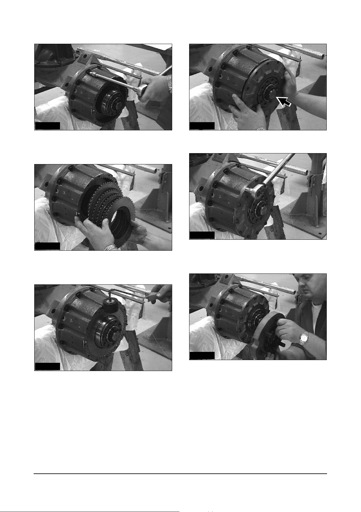
IDCD627P
7. Remove the gear cover.
IDCD628P
IDCD625P
5. Remove the friction disks and separater disks.
8. Loosen the gear cover by using a plastic hammer.
1
IDCD629P
IDCD626P
6. Brake parts : (1) sepratater disks,
(2) friction discs.
Power Train Disassembly & Assembly
2
9. Force the gear cover with 2 tire irons.
28

IDCD630P
10. Straighten the lock tab with a punch.
IDCD633P
13. Remove the hub.
1
IDCD631P
11. Remove spindle nut with a special tool.(Ref. No 2)
IDCD634P
14. Remove the inner wheel bearing (1).
IDCD632P
1
12. Remove the nut (1), washer (2), shield (3) and
outer hub bearing.
Power Train Disassembly & Assembly
3
2
IDCD635P
15. Remove the spindle with a hexagon socket 19 mm.
29

IDCD636P
16. Remove the spindle from the axle housing.
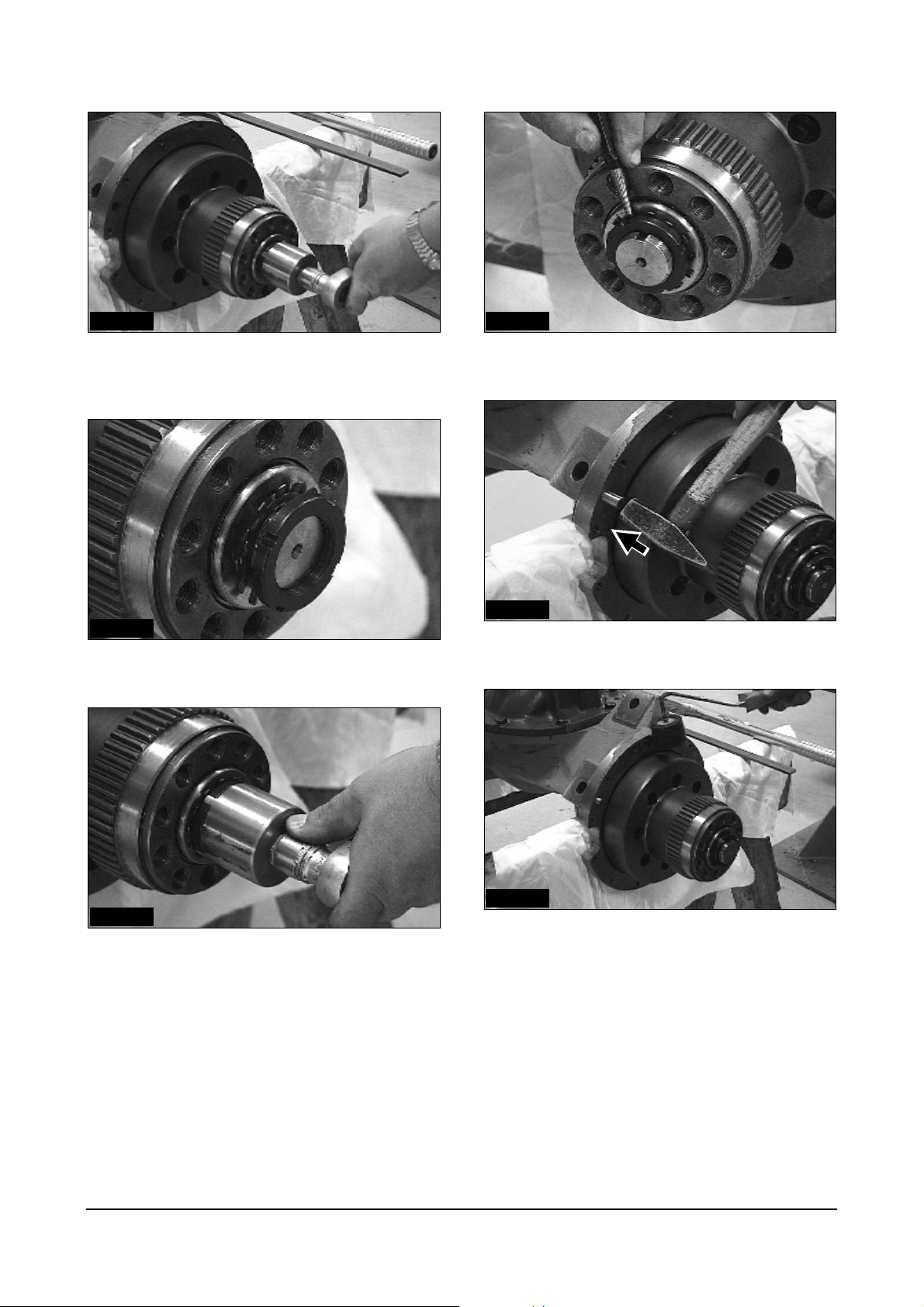
IDCD639P
19. Parts overview of the disassembled axle without
the differential and axle housing.
IDCD637P
17. Pull the axle shaft assembly with a pry bar and a
spindle mounting bolt.
IDCD638P
18. Remove the shaft assembly from the axle housing.
Power Train Disassembly & Assembly
30
Disassembly
Shaft As
Assembly
Shaft As
IDCD640P
1. Remove the roller bearing and the ring.
IDCD641P
2. Pull off the inner bearing ring with an suitable 2leg puller.
IDCD642P
1. Heat bearing to a temperature of 120°C (248°F).
IDCD643P
2. Install the heated inner bearing ring on the shaft.
2
1
IDCD644P
3. Mount the bearing (1) and the washer (2).
Power Train Disassembly & Assembly
31
Disassembly/Assembly
Brake Parts
IDCD645P
4. Heat the ring to a temperature of 135°C (275°F).
IDCD646P
5. Mount the heated ring with the plastic hammer.
IDCD647P
1. Remove the brake piston.
IDCD648P
2. Lubricate the seal and sliding surface with
transmission oil.
IDCD649P
3. Mount the brake piston using a press.
Power Train Disassembly & Assembly
32
Disassembly/Assembly
Hub Drive Axle
IDCD650P
1. Remove the inner bearing cup with hammer and
punch.
IDCD651P
2. Remove the outer bearing cup.
IDCD653P
4. Press in the outer bearing cup. (Tool Ref. No 3)
IDCD652P
3. Install seal with a special tool. (Tool Ref. No 7)
Power Train Disassembly & Assembly
33
Disassembly
Differential Assembly
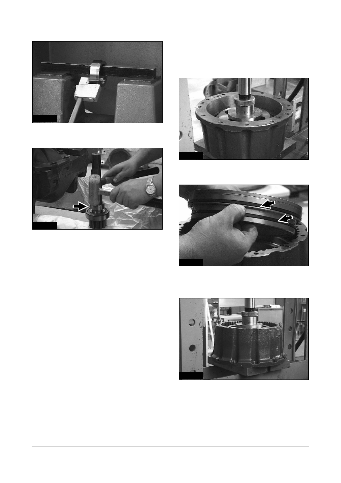
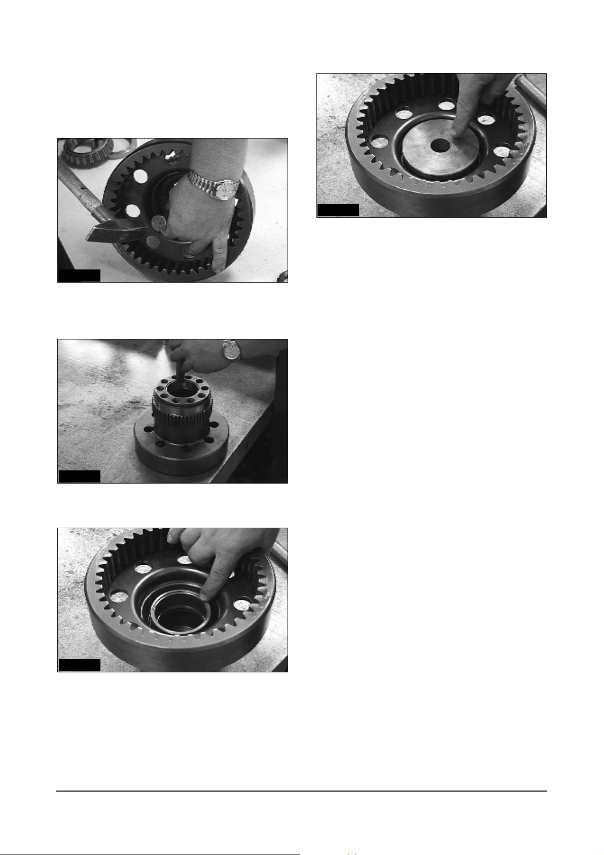
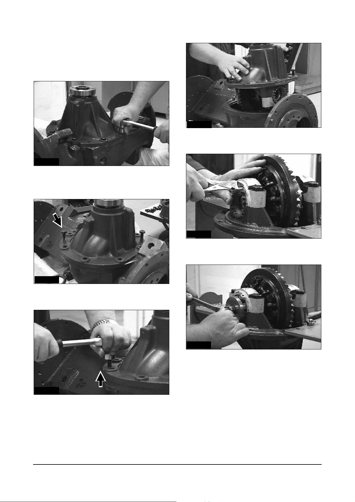
IDCD654P
1. Remove all differential carrier mounting bolts.
(hexagon socket 19mm)
IDCD655P
2. Install 2 jackbolts to carrier flange.
IDCD657P
4. Lift the differential carrier out of the axle housing.
IDCD658P
5. Remove the locking cotter pins.
IDCD659P
6. Loosen the retainer with special tool on both sides.
(Tool Ref. No 4)
IDCD656P
3. Press off the axle drive from the axle housing.
Alternately tighten jackbolts to separate carrier
from axle housing.
Power Train Disassembly & Assembly
34
Disassembly
Bevel Pinion
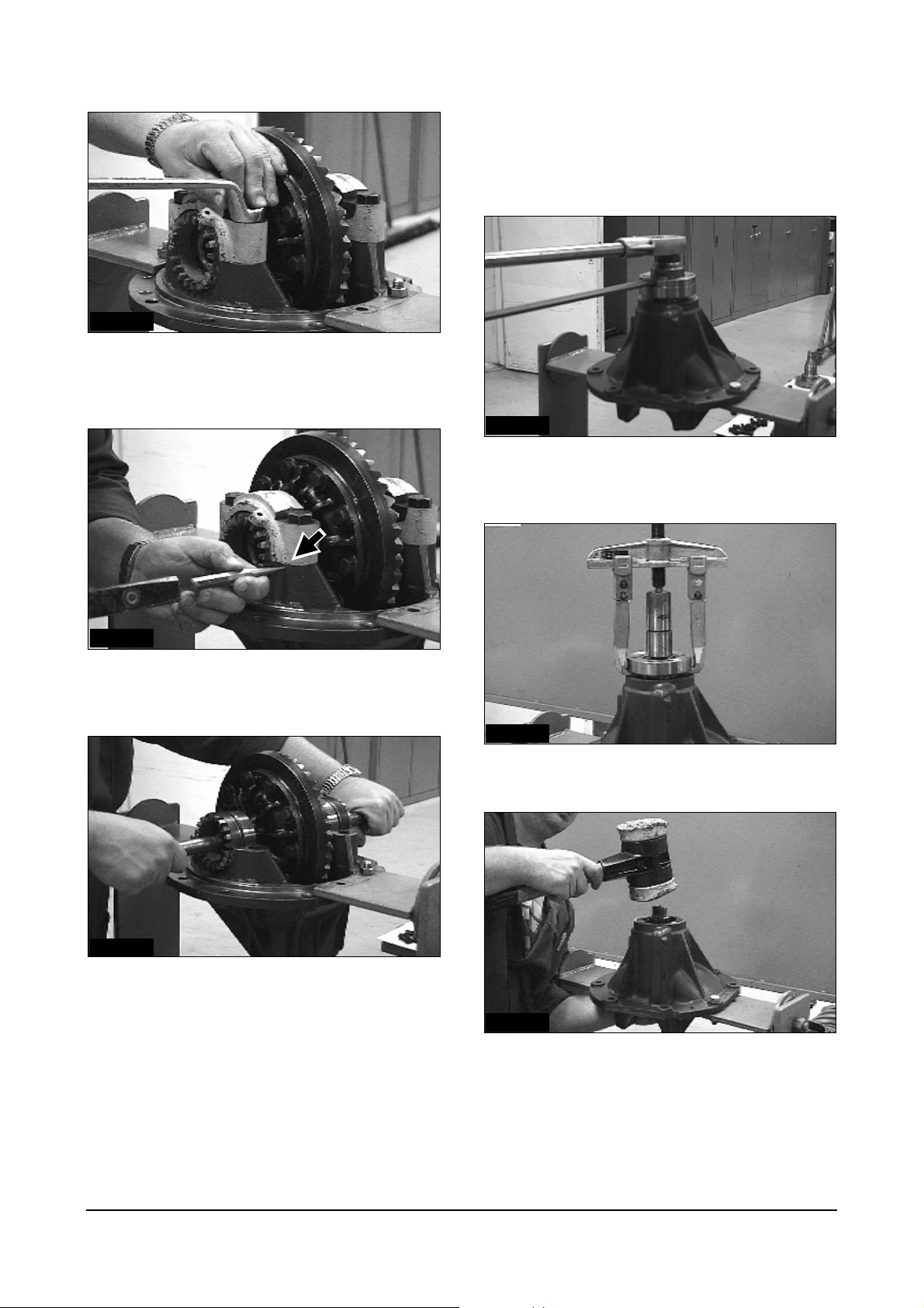
IDCD660P
7. Loosen the bearing bolts.
(ring spanner 19mm)
IDCD661P
8. Mark the bearing parts with hammer and centre
punch to guarantee correct side mounting.
IDCD663P
1. Loosen yoke retaining nut with a special tool.
(Tool Ref. No 7) (Hexagon socket 42mm)
IDCD664P
2. Pull off the yoke with a suitable gear puller.
IDCD662P
9. Lift the differnential assembly out of the axle
housing.
Power Train Disassembly & Assembly
IDCD665P
3. Remove pinion from inside carrier while gently
tapping pinion shaft from yoke end using a soft
face mallet.
35
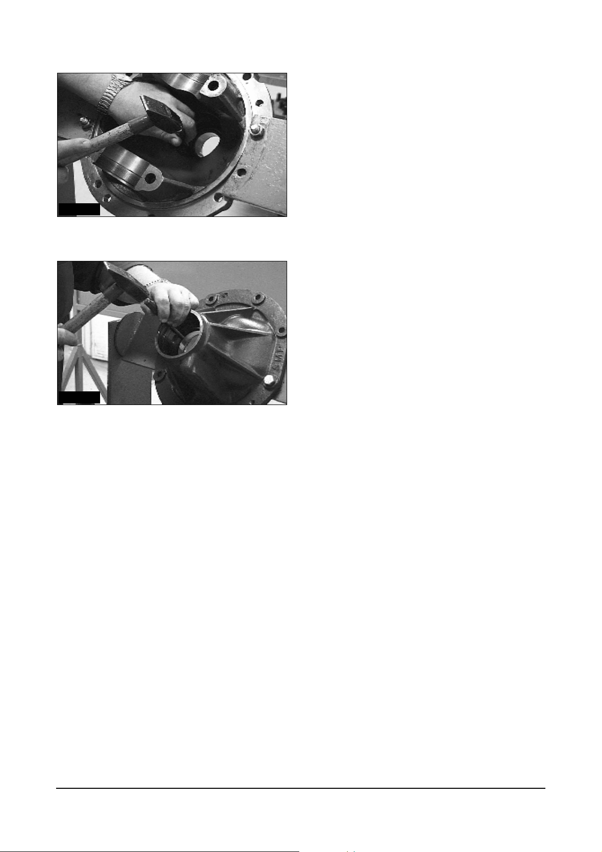
IDCD666P
4. Remove the bevel pinion bearing cup and seal.
IDCD667P
5. Carefully drive out the internal bevel pinion
bearing cup.
Power Train Disassembly & Assembly
36
Adjustment
Bevel Pinion
4. Calaulate the shimpack thickness according to the
following formula.
Shimpack thickness = A-(127+B+C)
Example) if A=160.50, B=32.00, C=+0.05
Then, shimpack thickness
= 160.50-(127+32.00+0.55) = 1.45mm
* To minimize the measuring error, measure
three places at least and average them.
IDCD668P
1. Measure the depth from center of diff. carrier to
the seat of pinion bearing cup. (Dimension A)
2. Measure the width of pinion bearing.
(Dimension B)
IDCD671
5. Shims of calculated thickness laid into bearing
seat.
IDCD672P
6. Install bearing cup.
IDCD670P
3. Check the etched value on the pinion face.
(Dimension c)
*unit : mm
Power Train Disassembly & Assembly
IDCD673P
7. Install crown gear, differential assy and lightly
torque bridge bilts.
37

8. Install bearing nuts for correct bridge position and
lightly torque them to achieve bearing preload.
11. When drag is correct, mark position of nuts both
on nuts and bridge.
9. Tap on differential on both sides to achieve correct
bearing cone position, rotate differential (3-5
times).
10. Check drag 19.6 N.m (14.5 lb.ft) on rotating
differential.
12. After marking of position remove differential assy.
Power Train Disassembly & Assembly
38
Adjustment
Disassembly/Assembly of
Bevel Pinion
Assembly
Bevel Pinion
IDCD679P
1. Pull the tapered roller bearing of the bevel pinion
using a two leg puller.
IDCD680P
2. Install the roller bearing with a press.
IDCD681P
1. Install cup of rear pinion bearing
IDCD682P
2. Install spacer and shims on pinion (basic
thickness 1.5mm (0.059 in)).
IDCD683P
3. Install bearing cone.
Power Train Disassembly & Assembly
39

Disassembly/Assembly
Differential
IDCD684P
4. Tap bearing cone to correct position(Rotate pinion
3-5 times)
IDCD685P
5. Assemble yoke and nut and tighten flange nut to
180 ±15 N∙m (133±11 lb ∙ft)
IDCD687P
1. Loosen differential housing bolts to disassemble
differential.
IDCD688P
2. After loosening the bolts, lift the differential
housing carefully.
IDCD686P
6. Measure the rolling torque. The value of rolling
torque should be 1.5~2.0 N∙m (1.1~1.5 lb∙ft)
7. If the rolling torque exceeds 2 N∙m, add one shim
and if it is lower than 1.5 N∙m, subtract one shim
8. When the adjustment is correct, disassemble the
nut and the yoke.
Assemble the oil seal and yoke again and then
tighten the nut to 180 ±15 N∙m (133±11 lb∙ft).
Power Train Disassembly & Assembly
IDCD689P
3. Overview of the differential parts.
40

IDCD690P IDCD693P
4. Grease all sliding surfaces with Molycote BR-2
also during assembly.
7. Check the greasing of all sliding surfaces and
position of the cross shaft.
IDCD691P
5. Assemble cross shaft with small differential bevel
gears and thrust washers and place into half the
differential housing.
IDCD692P
6. CAUTION : The thrust washer and cross shafts
have flats to prevent washer rotation with bevel
gears.
Power Train Disassembly & Assembly
IDCD694P
8. The flat side of the shaft must be on top. Join
differential housing halves so marks are aligned.
IDCD695P
9. Secure the bolts with Loctite 242 before installing.
41

Assembly
Crown wheel/Adjustment
IDCD696P
10. Secure the bolts to the instructed torque (85 ± 6
N·m (63 ± 4.5 lb·ft).
IDCD697P
1. Torque of the crown wheel bolts 80 ± 6 N·m
(60 ± 4 lb·ft).
IDCD698P
2. Assemble the crown wheel with bearing support
and retainers.
First turn the retainers to the marked position (for
adjusting turn both retainers on the same side to
keep the constant bearing preload of the crown
wheel !) (Tool Ref. No 4)
Power Train Disassembly & Assembly
42

IDCD699P IDCD702P
3. Strike the crown wheel left and right to insure
position.
6. Rotate gears and examine contact pattern.
IDCD700P
4. Rotate the axle drive through 100° and check the
tooth backlash at several points of the crown
wheel using a dial gauge. The tooth backlash
should be 0.15 - 0.25mm. (0.006 - 0.010 in)
IDCD703P
7. Depth of engagement of the bevel pinion is
correctly set, when the contact pattern appears as
shown in diagram.
IDCD704P
IDCD701P
5. In order to check the depth of engagement of the
bevel pinion, apply a coating of a gear tooth
pattern checking material.
8. The contact pattern in diagram shows too great a
depth of engagement.
Power Train Disassembly & Assembly
43

IDCD705P
9. With a contact pattern as shown in diagram the
bevel pinion has too little an engagement. The
shim of the bevel pinion should be rechecked if
the contact pattern as shown in fig. 7 is not
achieved.
IDCD708P
12. Before assembling the yoke, coat the seal with
grease.
IDCD709P
13. Heat the yoke to 130°C (266°F).
IDCD706P
10. If the depth of engagement is correct secure the
retainers with locking cotter pins.
IDCD710P
14. Install the yoke.
IDCD707P
11. Install the seal flush with carrier housing.
(Tool Ref. No 6)
CAUTION : Take care that the sealing lips will not be
damaged !
Power Train Disassembly & Assembly
44

Assembly
Carrier Diff
IDCD711P
15. Apply Loctite 242 to the yoke retaining nut.
IDCD712P
16. Tighten the nut to the instructed torque of
180 ± 15 N·m (133 ±11 lb·ft). (Tool Ref. No 8)
IDCD713P
1. Install the dowels for the carrier housing.
IDCD714P
2. Degrease the flange area and apply with Loctite
17430 sealant.
IDCD715P
3. Install the differential carrier assembly.
Power Train Disassembly & Assembly
45

IDCD716P IDCD719P
4. Tighten the carrier assembly housing on the axle
housing to the instructed torque 115 ± 15 N·m
7. Drive the plug flush with axle housing.
(85 ± 11 lb·ft).
IDCD717P
5. Coat the plug with Loctite 17430.
IDCD718P
6. Install the plug.
IDCD720P
8. Insert the pre-assembled shaft assembly.
IDCD721P
9. Tap the shaft assembly into the differential and
axle housing.
Power Train Disassembly & Assembly
46

IDCD722P IDCD725P
10. Install the spindle into the drive axle. Apply Loctite
242 to secure bolts.
13. Fully pack outer roller bearing into grease and
install into hub. Install shield and nut.
IDCD723P IDCD726P
11. Tighten all bolts of the spindle to a torque of
115 ± 15 N·m (85 ± 11 lb·ft).
IDCD724P
12. Install the inner tapered roller bearing.
14. Tighten the hub nut to 135 N·m (100 lb·ft).
(Tool Ref. No 2)
IDCD727P
15. Knock with the percussion drive and rotate the
hub drive axle to insure the seating of the
bearings.
Power Train Disassembly & Assembly
47
IDCD728P IDCD731P
16. Loosen the nut of the hub drive axle to install the
safety washer. (Tool Ref. No 2)
19. Lock the nut with a punch.
IDCD729P
17. Install the safety washer and the nut.
IDCD730P
18. Tighten the nut to 50 ± 5 N·m (37 ± 11 lb·ft).
(Tool Ref. No 2)
IDCD732P
20. Install 2 dowels on both sides.
IDCD733P
21. Degrease the contact area and seal with Loctite
17430.
Power Train Disassembly & Assembly
48
IDCD734P IDCD737P
22. Install and tighten the gear cover to 55 ± 10 N·m
(41 ± 7.5 lb·ft).
25. Put on the end cover.
IDCD738P
IDCD735P
23. Install the friction discs and plates in the gear
cover. First mount a plate outer.
26. Tighten the end cover with 28 ± 7 N·m (21 ± 5
lb·Ift)
IDCD739P
IDCD736P
24. Degrease and seal the gear cover to end
coverwith Loctite 17430.
Power Train Disassembly & Assembly
27. Install the adapter for wheels.
49

IDCD740P
28. Tighten the adapter to 285 N·m (210 lb·ft).
Power Train Disassembly & Assembly
50
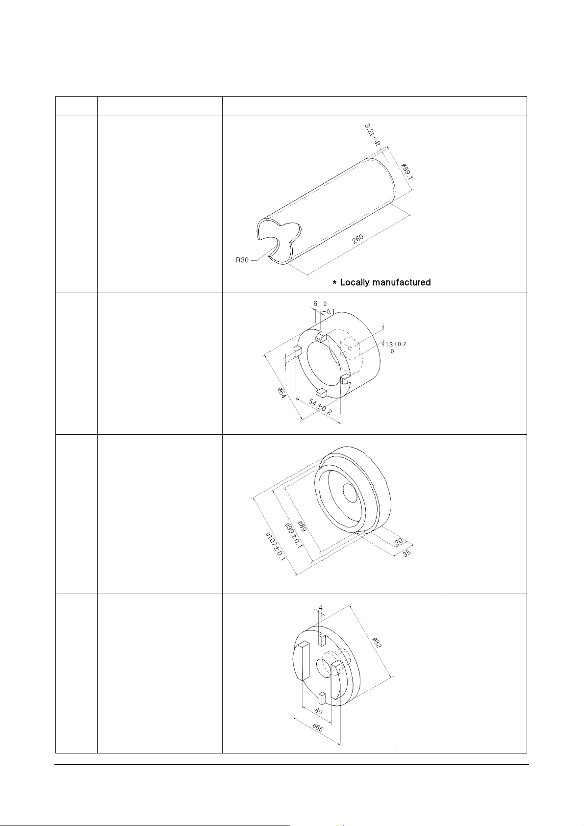
Special Service Tools
Ref.No Tool Name Illustration Remark
Transmission
1
2
Piston return spring
Compressor
Drive Axle
Hub Bearing Lock
Nut Installer
DAEWOO Tool
No.: T059
Drive Axle
3
4
Hub Bearing Cup
Installer
Drive Axle
Differential
Retainer Installer
DAEWOO Tool
No.: T020
DAEWOO Tool
No.: T001
Power Train Disassembly & Assembly
51
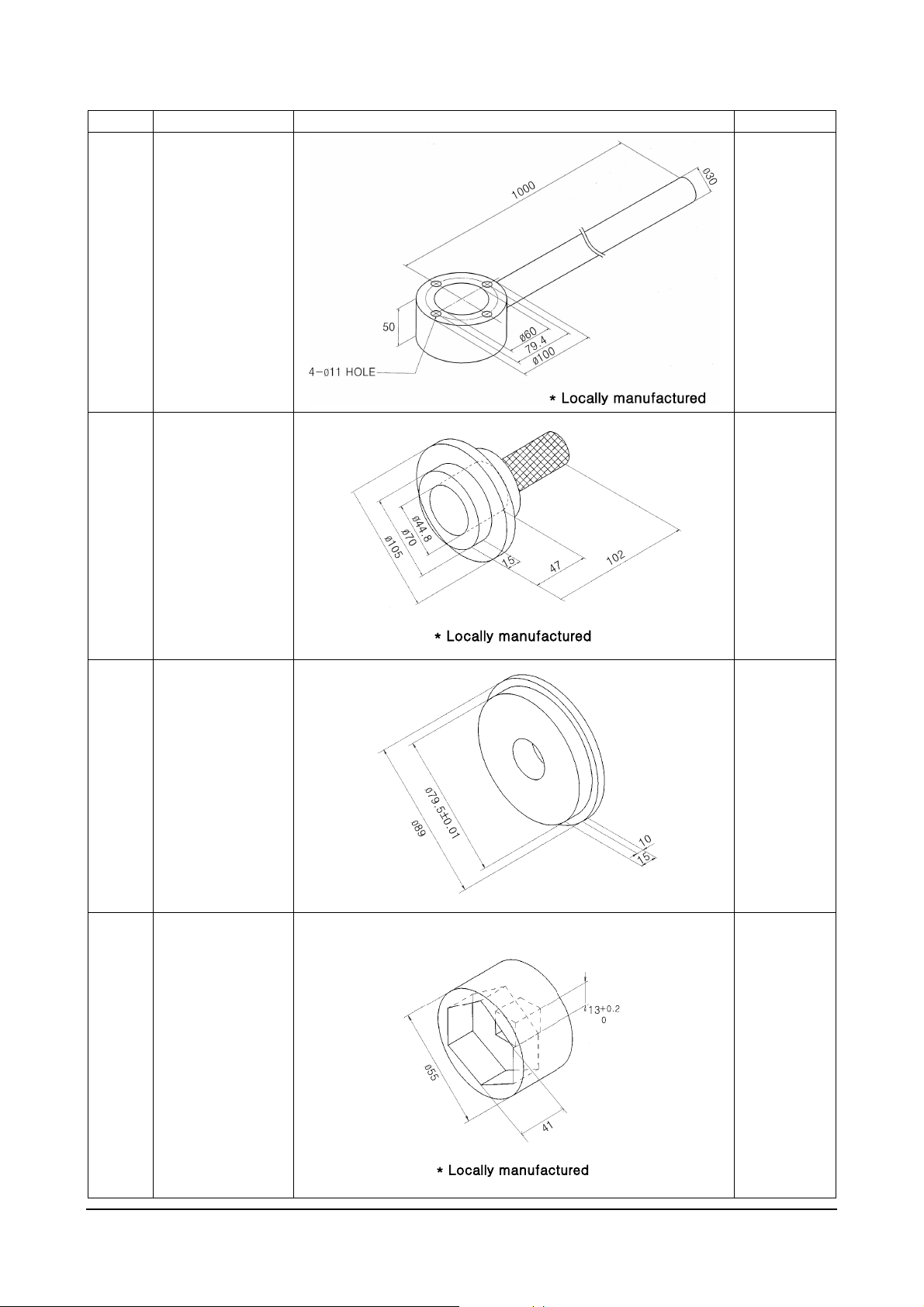
Ref.No Tool Name Illustration Remark
Drive Axle
5
Yoke N ut
Installer
Drive Axle
Input Shaft
6
7
Lip-seal
Installer
Drive Axle
Hub Lip-seal
Installer
DAEWOO
Tool
No.: T022
Drive Axle
8
Power Train Disassembly & Assembly
Yoke N ut
Installer
52
 Loading...