

Doosan DP158LCF, DP158LCS, DP180LAS, DP158LDS, DP158LDF Operation & Maintenance Manual
...
950106-01352
GENERATOR DIESEL ENGINE
3. Performance and specifications
21
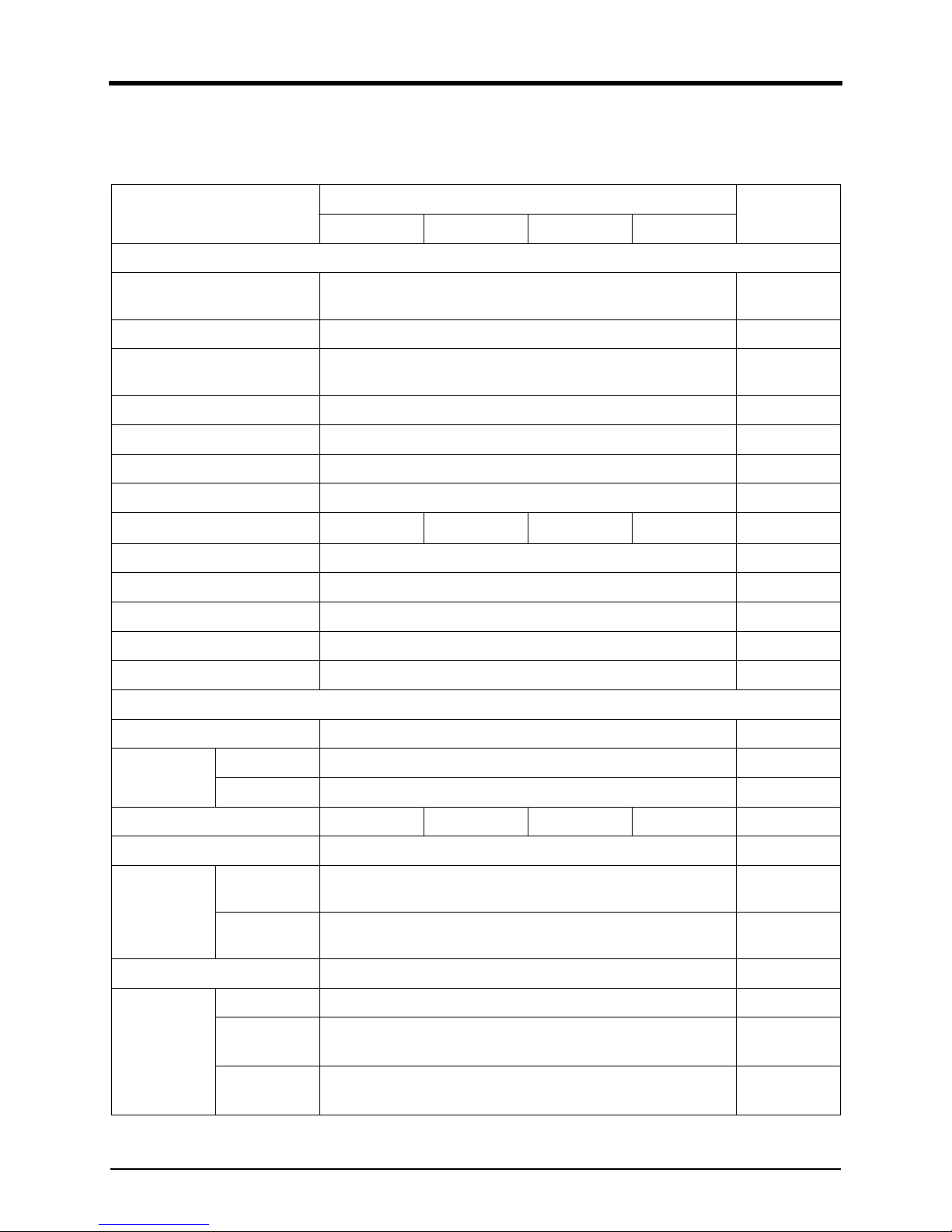
Engine specifications and performance
Engine Specifications
Item
DP158L
Remarks
DP158LCS DP158LCF DP158LDS DP158LDF10
General Information
Engine types
Water-cooled, 4cycle, V-type, Turbo charger & inter cooled (air to
air)
Cylinder liner type Wet type liner
No. of cylinder - bore x stroke
(mm)
8 - 128 X 142
Total displacement(cc) 14,618
Compression ratio 15 : 1
Rotation Counter clockwise viewed from flywheel
Firing order 1-5-7-2-6-3-4-8
Injection timing (°) (BTDC) 23°±1° 18°±1° 23°±1° 18°±1°
Dry weight (kg) 1,155 With fan
Dimension (L x W x H) (mm) 1,274 X 1,138 X 1,207 With fan
Flywheel housing SAE NO.1M
Flywheel Clutch NO.14M
No. of teeth on flywheel 160
Cooling System
Cooling method Fresh water forced circulation
Coolant capacity (L)
Engine only Approx. 20
With radiator Approx. 79 (Air on 43°C) / Approx 90 (Air on 52°C)
Coolant flow rate (L /min) 660 550 660 550
Pressure cap (kPa) Max. 49
Water temperature (°C)
Max. for stand
by and prime
103
Before start of
full load
40
Water pump Centrifugal type driven by belt
Thermostat
Type Wax-pellet type
Opening temp.
(°C)
71
Full open temp.
(°C)
85
3. Performance and specifications
22
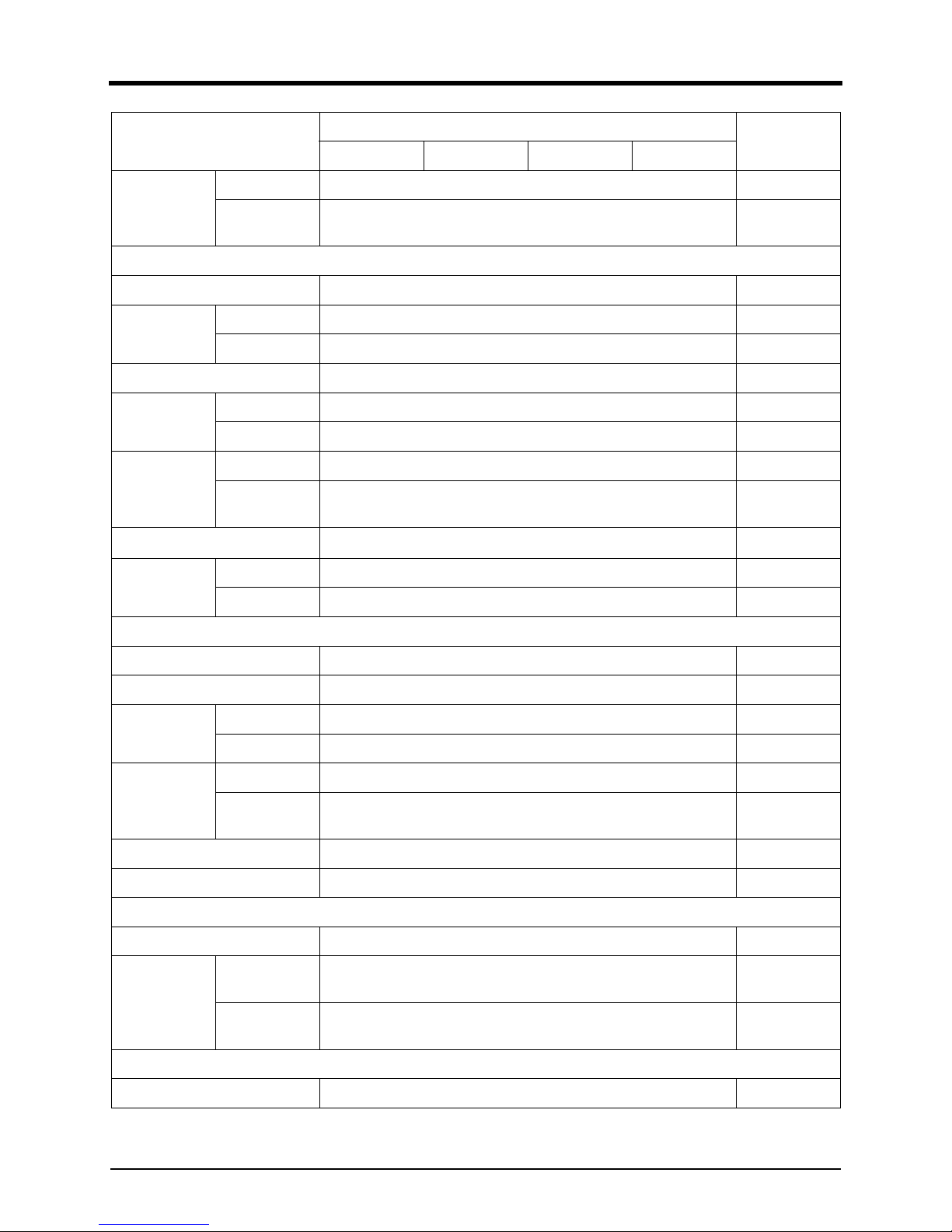
Cooling fan
Type Blow Type
Diameter blades
915mm - 7 blades
Lubrication System
Lubrication method Fully forced pressure feed type
Oil pump
Type Gear type
Driving type Driven by crankshaft gear
Oil filter Full flow, Cartridge type
Oil capacity (L)
Max. 22
Min. 13
Lubrication oil
pressure (kPa)
Idle speed Min. 100
Governed
speed
Min. 250
Max. oil temperature (°)
120
Oil specification
Oil class Above API CD
SAE 15W/40
Fuel System
Injection pump Bosch in-line "P" type
Governor Electric type
Fuel feed
pump
Type Mechanical type injection pump
Capacity (L/hr) 315
Injection nozzle
Type Multi hole type
Opening pressure (MPa)
28
Fuel filter Full flow, Cartridge type with water drain valve
Fuel Used Diesel fuel oil
Intake/Exhaust System
Max. back pressure (kPa) 5.9
Max. intake air
restriction (kPa)
With clean filter
element
2.16
With dirty filter
element
6.23
Cylinder block/head
Valve system type Overhead valve type
Item
DP158L
Remarks
DP158LCS DP158LCF DP158LDS DP158LDF10
3. Performance and specifications
23
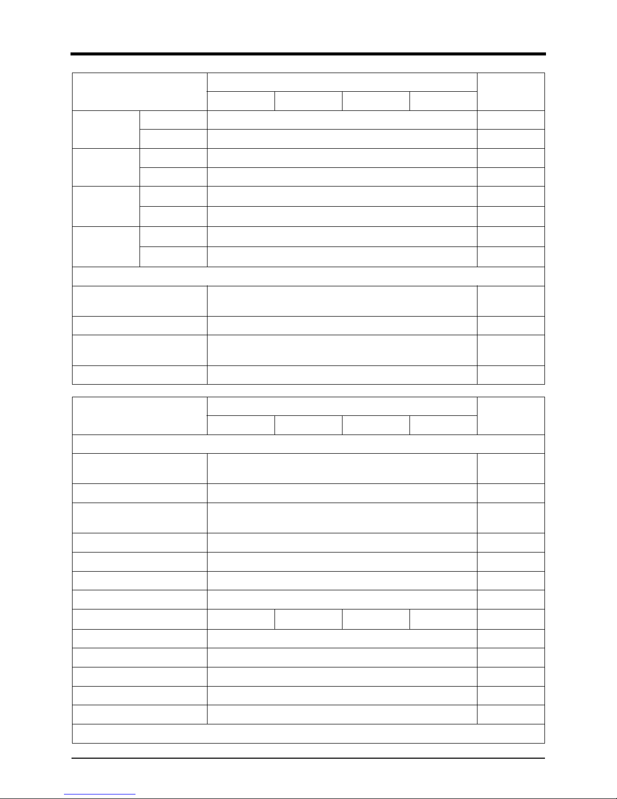
No. of valve
(per cylinder)
Intake 1
Exhaust 1
Valve lashes
(at cold) (mm)
Intake 0.25
Exhaust 0.35
Intake valve (°)
Opening
24° (BTDC)
Close
36° (ABDC)
Exhaust valve
(°)
Opening
63° (BBDC)
Close
27° (ATDC)
Electrical System
Alternator voltage - capacity (V A)
27.5 - 45
Voltage regulator Built-in type IC regulator
Starting motor voltage - capacity
(V - kW)
24 - 7.0
Battery capacity 2-200Ah (recommended)
Item
DP180L
Remarks
DP180LBS DP180LBF DP180LAS DP180LAF
General Information
Engine types
Water-cooled, 4cycle, V-type, Turbo charger & inter cooled (air to
air)
Cylinder liner type Wet type liner
No. of cylinder - bore x stroke
(mm)
10 - 128 X 142
Total displacement(cc) 18,273
Compression ratio 15 : 1
Rotation Counter clockwise viewed from flywheel
Firing order 1-6-5-10-2-7-3-8-4-9
Injection timing (°) (BTDC) 21°±1° 19°±1° 21°±1° 19°±1°
Dry weight (kg) 1,250 With fan
Dimension (L x W x H) (mm) 1,592 x 1,389 x 1,223 With fan
Flywheel housing SAE NO.1M
Flywheel Clutch NO.14M
No. of teeth on flywheel 160
Cooling System
Item
DP158L
Remarks
DP158LCS DP158LCF DP158LDS DP158LDF10
3. Performance and specifications
29
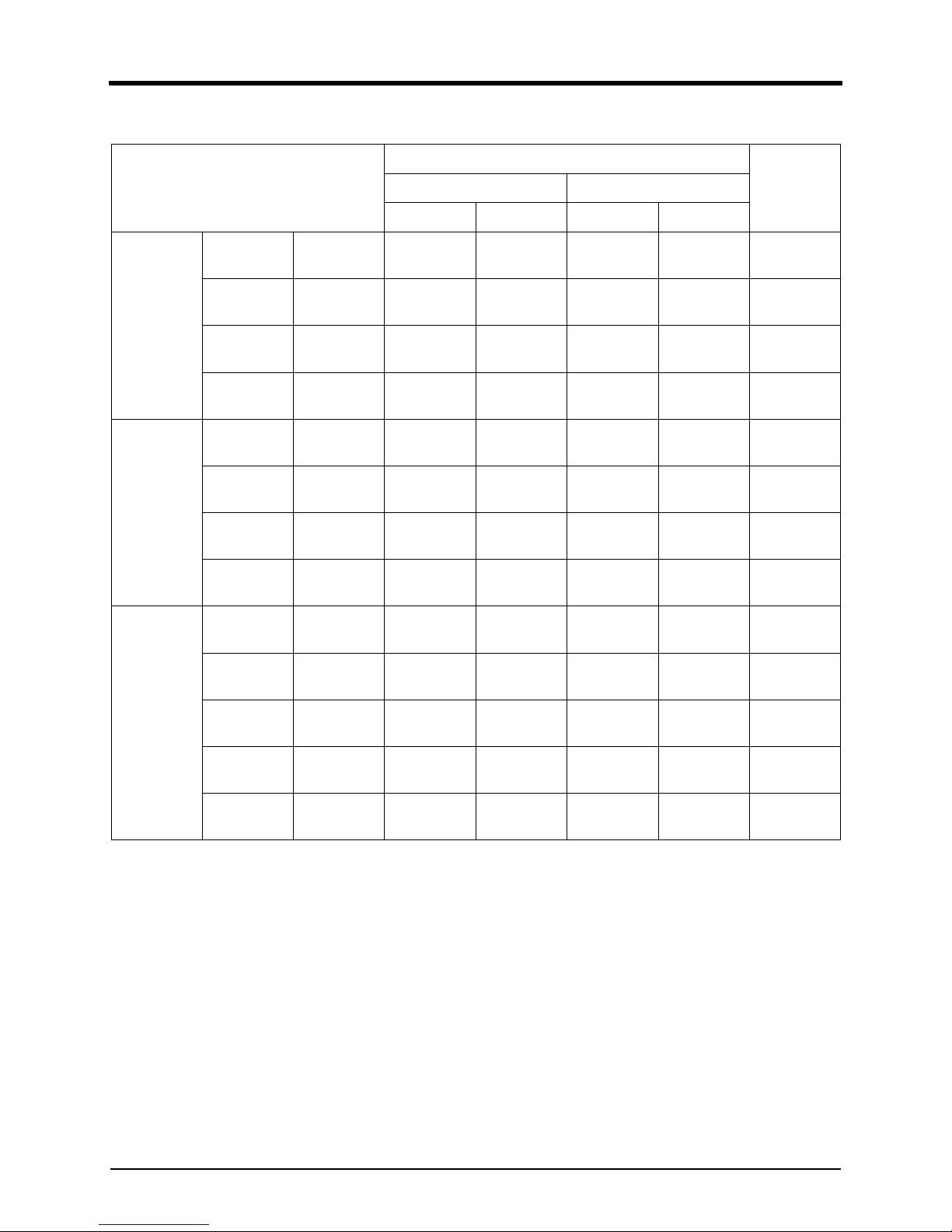
Gross Engine Output
Engine Model
Performance
RemarkPrime Stand by
PS kWm PS kWm
DP158L
DP158LCS
60Hz
(1,800rpm)
634 466 697 513
DP158LCF
50Hz
(1,500rpm)
555 408 610 449
DP158LDS
60Hz
(1,800rpm)
687 505 756 556
DP158LDF
50Hz
(1,500rpm)
630 464 693 510
180L
DP180LBS
60Hz
(1,800rpm)
817 601 899 661
DP180LAS
60Hz
(1,800rpm)
760 559 836 615
DP180LBF
50Hz
(1,500rpm)
756 556 832 612
DP180LAF
50Hz
(1,500rpm)
682 502 750 552
DP222L
DP222LCS
60Hz
(1,800rpm)
1,023 753 1,126 828
DP222LCF
50Hz
(1,500rpm
894 657 983 723
DP222LBB
60Hz
(1,800rpm)
967 711 1,063 782
DP222LBF
50Hz
(1,500rpm)
821 604 903 664
DP222LAS
60Hz
(1,800rpm)
911 670 1,002 737
3. Performance and specifications
30
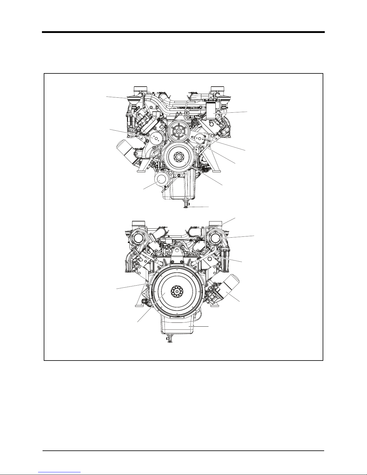
Exterior view drawing of the engine
Front/Rear(DP158L)
DV2213001A
1. Fuel Filter 6. Crankshaft Pulley 11. Engine Oil Supply Pipe
2.Breather 7.
Coo
ling Fan Pulley 12.Flywheel Housing
3.
Cool
ant Pump 8.Idle Pulley 13.Flywheel
4.Alternator 9.
Eng
ine Oil Return Pipe 14.Oil Pan
5.
Eng
ine Oil Drain Plug 10.Turbocharger 15.Oil Filter
1
2
3
4
5
6
7
8
9
10
11
15
14
13
12
3. Performance and specifications
31
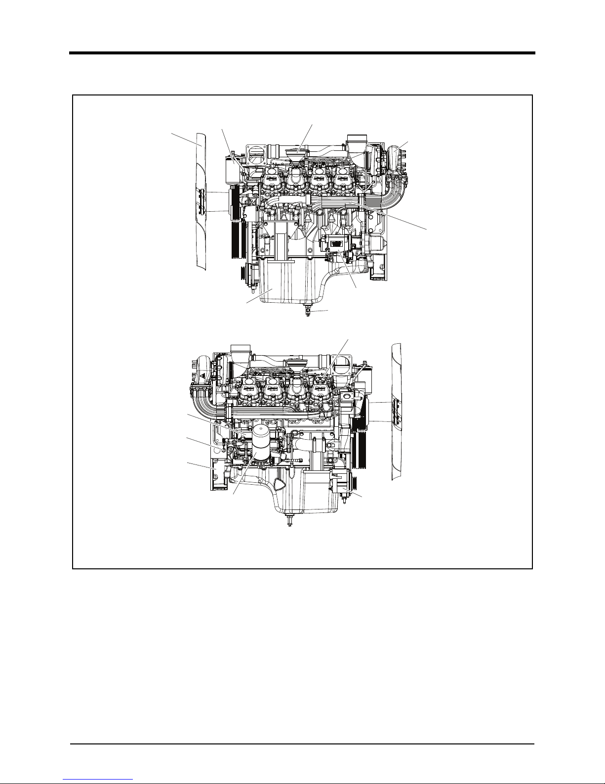
Left/Right(DP158L)
DV2213002A
1. Cooling Fan 6. Turbocharger 11. Flywheel Housing
2.Oil Pan 7.Breather 12.Oil Filter
3.
Eng
ine Oil Drain Plug 8.Fuel Filter 13.Alternator
4.Starter 9.Oil Cooler 14.Oil Cap
5.
Exh
aust Manifold 10.Tacho Sensor
1
8
7
5
4
2
14
13
12
11
10
9
3
6
3. Performance and specifications
http://www.brizmotors.ru/equipment/ctm/400/
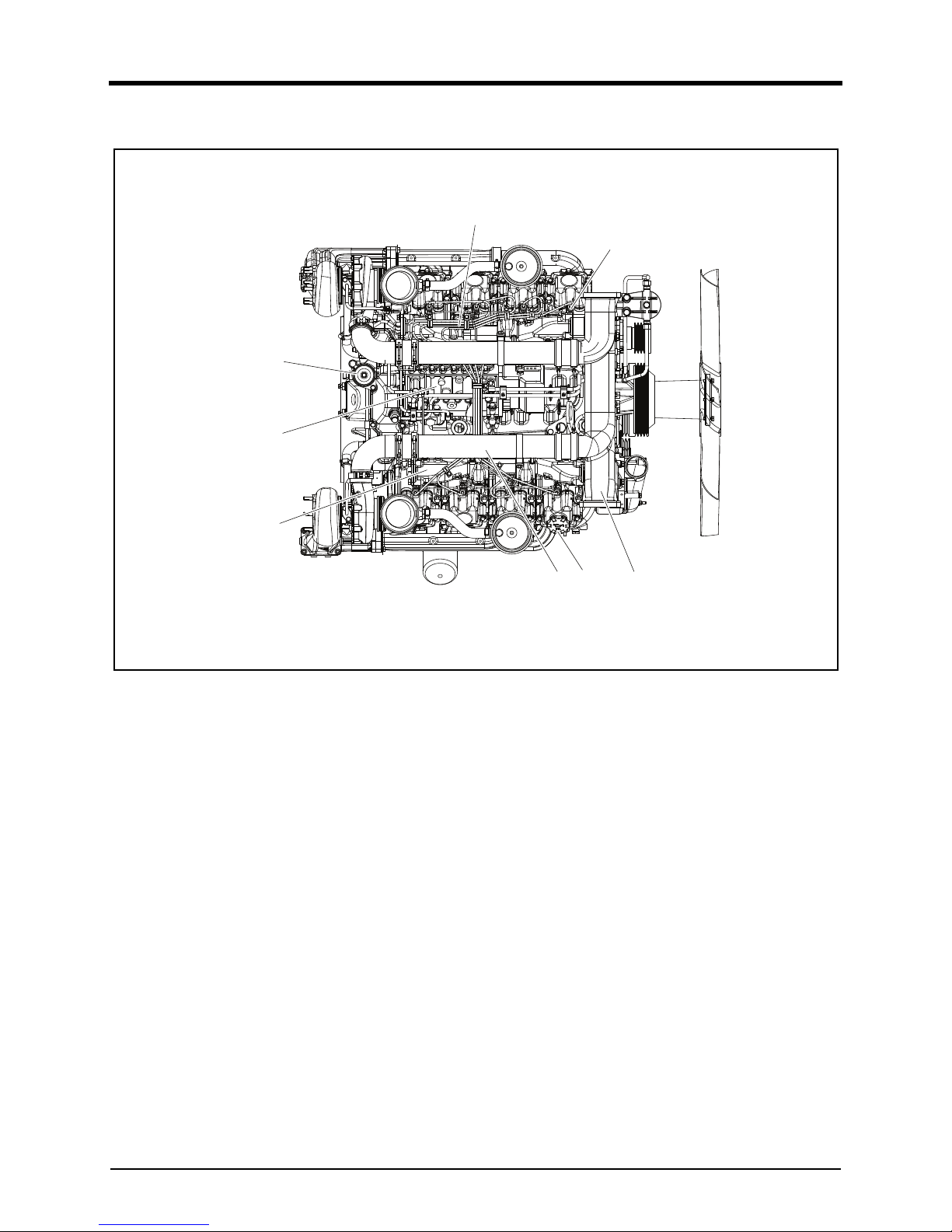
Top(DP158L)
DV2213003A
1. Injector 4. Fuel Injection Pump 7. Oil Filler Cap
2. Fuel Injection Pipe 5. Intake Manifold 8. Inlet Pipe
3.
Fuel Pre-Filter/Priming Pump 6. Intake Stake
1
2
3
4
5
67 8
3. Performance and specifications
39
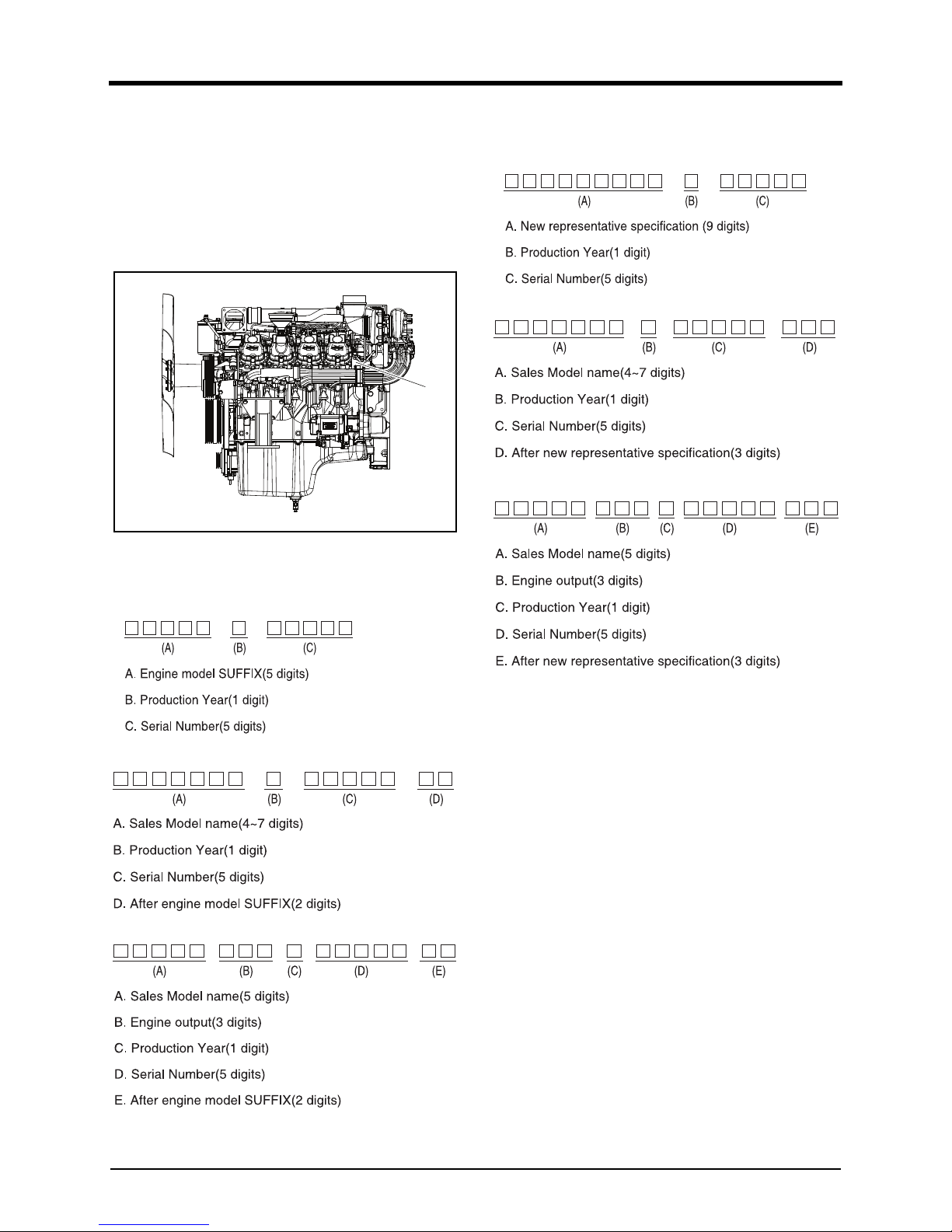
Engine identification number
Engine Code and Manufacturing Number
The engine code and manufacturing number are
engraved in the position marked (A) in the drawing.
These numbers are necessary to request quality assur-
ance or to order parts.
DV2213007A
Engine number engraving
• Type 1
• Type 2
• Type 3
• Type 4
• Type 5
• Type 6
A

41
4. Regular inspection
General information . . . . . . . . . . . . . . . . . . . . . . . . . . . . . . . . . . . . . . . . . . . . . . . . . . . . . . 43
General Information . . . . . . . . . . . . . . . . . . . . . . . . . . . . . . . . . . . . . . . . . . . . . . . . . . . . . 43
Routine Inspection . . . . . . . . . . . . . . . . . . . . . . . . . . . . . . . . . . . . . . . . . . . . . . . . . . . . . . 43
Regular inspection table . . . . . . . . . . . . . . . . . . . . . . . . . . . . . . . . . . . . . . . . . . . . . . . . . . 44
General Conditions . . . . . . . . . . . . . . . . . . . . . . . . . . . . . . . . . . . . . . . . . . . . . . . . . . . . . . 44
Use of Genuine Parts. . . . . . . . . . . . . . . . . . . . . . . . . . . . . . . . . . . . . . . . . . . . . . . . . . . . 45
Cooling system. . . . . . . . . . . . . . . . . . . . . . . . . . . . . . . . . . . . . . . . . . . . . . . . . . . . . . . . . . 46
General Information . . . . . . . . . . . . . . . . . . . . . . . . . . . . . . . . . . . . . . . . . . . . . . . . . . . . . 46
Coolant standards . . . . . . . . . . . . . . . . . . . . . . . . . . . . . . . . . . . . . . . . . . . . . . . . . . . . . . 46
Capacity of coolant. . . . . . . . . . . . . . . . . . . . . . . . . . . . . . . . . . . . . . . . . . . . . . . . . . . . . . 46
Checking the Coolant . . . . . . . . . . . . . . . . . . . . . . . . . . . . . . . . . . . . . . . . . . . . . . . . . . . . 46
Measurement of Coolant Concentration . . . . . . . . . . . . . . . . . . . . . . . . . . . . . . . . . . . . . . . 47
Discharging the coolant . . . . . . . . . . . . . . . . . . . . . . . . . . . . . . . . . . . . . . . . . . . . . . . . . . 48
Charging the Coolant . . . . . . . . . . . . . . . . . . . . . . . . . . . . . . . . . . . . . . . . . . . . . . . . . . . . 49
Cleaning the cooling circuit . . . . . . . . . . . . . . . . . . . . . . . . . . . . . . . . . . . . . . . . . . . . . . . . 49
Inter cooler . . . . . . . . . . . . . . . . . . . . . . . . . . . . . . . . . . . . . . . . . . . . . . . . . . . . . . . . . . . 50
Lubrication system . . . . . . . . . . . . . . . . . . . . . . . . . . . . . . . . . . . . . . . . . . . . . . . . . . . . . . . 51
General Information . . . . . . . . . . . . . . . . . . . . . . . . . . . . . . . . . . . . . . . . . . . . . . . . . . . . . 51
Engine oil standards. . . . . . . . . . . . . . . . . . . . . . . . . . . . . . . . . . . . . . . . . . . . . . . . . . . . . 51
Engine Oil Capacity . . . . . . . . . . . . . . . . . . . . . . . . . . . . . . . . . . . . . . . . . . . . . . . . . . . . . 52
Checking the Engine Oil. . . . . . . . . . . . . . . . . . . . . . . . . . . . . . . . . . . . . . . . . . . . . . . . . . 52
Replacement of Engine Oil . . . . . . . . . . . . . . . . . . . . . . . . . . . . . . . . . . . . . . . . . . . . . . . . 53
Replacement of Engine Filter . . . . . . . . . . . . . . . . . . . . . . . . . . . . . . . . . . . . . . . . . . . . . . 53
Fuel system . . . . . . . . . . . . . . . . . . . . . . . . . . . . . . . . . . . . . . . . . . . . . . . . . . . . . . . . . . . . 54
General Information . . . . . . . . . . . . . . . . . . . . . . . . . . . . . . . . . . . . . . . . . . . . . . . . . . . . . 54
Fuel Standards. . . . . . . . . . . . . . . . . . . . . . . . . . . . . . . . . . . . . . . . . . . . . . . . . . . . . . . . . 54
Water draining from fuel filter . . . . . . . . . . . . . . . . . . . . . . . . . . . . . . . . . . . . . . . . . . . . . . 55
Replacing fuel filter. . . . . . . . . . . . . . . . . . . . . . . . . . . . . . . . . . . . . . . . . . . . . . . . . . . . . . 55
Preventing fuel contamination . . . . . . . . . . . . . . . . . . . . . . . . . . . . . . . . . . . . . . . . . . . . . . 56
Fuel injection pump . . . . . . . . . . . . . . . . . . . . . . . . . . . . . . . . . . . . . . . . . . . . . . . . . . . . . 56
Cleaning the fuel pre-filter. . . . . . . . . . . . . . . . . . . . . . . . . . . . . . . . . . . . . . . . . . . . . . . . . 56
Air bleeding in the fuel circuit . . . . . . . . . . . . . . . . . . . . . . . . . . . . . . . . . . . . . . . . . . . . . . 57
Injector maintenance . . . . . . . . . . . . . . . . . . . . . . . . . . . . . . . . . . . . . . . . . . . . . . . . . . . . . 57
Fuel injection nozzle. . . . . . . . . . . . . . . . . . . . . . . . . . . . . . . . . . . . . . . . . . . . . . . . . . . . . 57
Removal of nozzle . . . . . . . . . . . . . . . . . . . . . . . . . . . . . . . . . . . . . . . . . . . . . . . . . . . . . . 58
Installation nozzle . . . . . . . . . . . . . . . . . . . . . . . . . . . . . . . . . . . . . . . . . . . . . . . . . . . . . . . 59
Note for cleaning nozzle. . . . . . . . . . . . . . . . . . . . . . . . . . . . . . . . . . . . . . . . . . . . . . . . . . 59
Checking the injection timing. . . . . . . . . . . . . . . . . . . . . . . . . . . . . . . . . . . . . . . . . . . . . . . 59
Adjusting injection timing. . . . . . . . . . . . . . . . . . . . . . . . . . . . . . . . . . . . . . . . . . . . . . . . . . 60
Intake/exhaust system . . . . . . . . . . . . . . . . . . . . . . . . . . . . . . . . . . . . . . . . . . . . . . . . . . . . 61
General Information . . . . . . . . . . . . . . . . . . . . . . . . . . . . . . . . . . . . . . . . . . . . . . . . . . . . . 61
Air Filter . . . . . . . . . . . . . . . . . . . . . . . . . . . . . . . . . . . . . . . . . . . . . . . . . . . . . . . . . . . . . 61

42
Disassembly of air filter . . . . . . . . . . . . . . . . . . . . . . . . . . . . . . . . . . . . . . . . . . . . . . . . . . 61
Cleaning of the Air Filter Element . . . . . . . . . . . . . . . . . . . . . . . . . . . . . . . . . . . . . . . . . . . 62
Changing the air filter element . . . . . . . . . . . . . . . . . . . . . . . . . . . . . . . . . . . . . . . . . . . . . 63
Turbocharger . . . . . . . . . . . . . . . . . . . . . . . . . . . . . . . . . . . . . . . . . . . . . . . . . . . . . . . . . . 63
Routine check and serving the turbocharger . . . . . . . . . . . . . . . . . . . . . . . . . . . . . . . . . . . 63
Disassembly and cleaning a turbocharger . . . . . . . . . . . . . . . . . . . . . . . . . . . . . . . . . . . . . 63
Cylinder block/head . . . . . . . . . . . . . . . . . . . . . . . . . . . . . . . . . . . . . . . . . . . . . . . . . . . . . . 64
Valve Clearance . . . . . . . . . . . . . . . . . . . . . . . . . . . . . . . . . . . . . . . . . . . . . . . . . . . . . . . . 64
Adjusting the Valve Clearance . . . . . . . . . . . . . . . . . . . . . . . . . . . . . . . . . . . . . . . . . . . . . 64
Tightening Cylinder Head Bolt . . . . . . . . . . . . . . . . . . . . . . . . . . . . . . . . . . . . . . . . . . . . . . 65
Cylinder Compression Pressure. . . . . . . . . . . . . . . . . . . . . . . . . . . . . . . . . . . . . . . . . . . . . 66
Electric system. . . . . . . . . . . . . . . . . . . . . . . . . . . . . . . . . . . . . . . . . . . . . . . . . . . . . . . . . . 67
Battery . . . . . . . . . . . . . . . . . . . . . . . . . . . . . . . . . . . . . . . . . . . . . . . . . . . . . . . . . . . . . . . 67
Starter . . . . . . . . . . . . . . . . . . . . . . . . . . . . . . . . . . . . . . . . . . . . . . . . . . . . . . . . . . . . . . . 67
Others/driving system. . . . . . . . . . . . . . . . . . . . . . . . . . . . . . . . . . . . . . . . . . . . . . . . . . . . . 68
V-Belt . . . . . . . . . . . . . . . . . . . . . . . . . . . . . . . . . . . . . . . . . . . . . . . . . . . . . . . . . . . . . . . 68
4. Regular inspection
43
General information
General Information
As time passes after purchasing an engine, each of the
engines parts age and initial engine performance cannot
be maintained.
Regular inspection and replacement according to the
recommended regular inspection table allows you to
maintain an engine with the optimum conditions and best
performance for a long period and prevent unexpected
accidents in advance.
Users are responsible for the proper operation and main-
tenance of engines. Engines should be inspected and
replaced by officially-certified technicians in a workspace
with the specified tools and facilities. Observe the
following instructions to perform inspections.
1. Perform inspections on a flat floor without a slope.
2. Excluding extreme circumstances, only perform
inspection while the engine is stopped.
3. Disconnect the '-' terminal of the battery before
performing an inspection.
4. Perform inspection in a well ventilated space.
5. Use a wooden prop or lift when working under t
he
e
ngine.
Routine Inspection
Routine inspection is an inspection performed by an
engine operator before operating the engine. It should be
performed to protect operator's safety, as well as the
engine.
The following is a minimal check list.
1. Check whether the engine smoothly starts and t
he
l
evels of fuel, oil, and coolant are within the normal
range.
2. Check if any discharged emissions are colored and if
the exhaust contains toxic gas elements.
3. Check whether abnormal noise occurs after starti
ng
an e
ngine or not.
4. Check whether oil or water is leaking.
DANGER
• Wait until the engine is sufficiently cooled before
starting inspection after operating the engine.
Otherwise, you may be burned.
• You may be poisoned by the emission when
starting an engine in a closed space. Perform
inspection at the well-ventilate space.
• Unless absolutely compelled, do not perform
inspection under an engine.
• Do not be close to fire when inspecting an
engine. Fuel, oil, or batteries may generate gas,
causing fire.
• If inspecting the engine while it is running,
do
n
ot wear accessories such as necklaces, rings,
watches or gloves. Such accessories may
become stuck in rotating parts while the engine
is running and may cause serious bodily injury.
CAUTION
• Incorrect inspection methods may cause of
engine faults.
• Cleaning an engine with liquids such as water
or
w
ax may cause breakdown of electrical parts.
• Be careful when handling batteries, cables, a
nd
el
ectrical wirings because current flows thr
ough
t
hose parts.
• Do not put heavy things or apply excessive force
or impact on the fuel-related units.
• Make sure that you connect the battery terminal
('+' and '-') to the right terminal. Connecting th
e
'
+' and '-' terminals to the wrong terminal m
ay
cause
damage to the electrical unit parts and fire.
4. Regular inspection
44
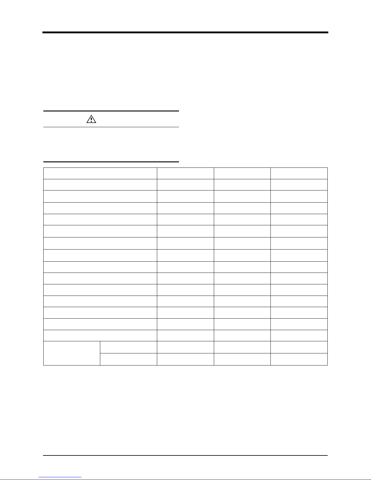
Regular inspection table
General Conditions
Regular inspection and replacement according to the
recommended regular inspection table allows you to
maintain the engine with optimum conditionsand best
performance for a long period and prevent unexpected
accidents in advance.
( ○
:
Inspection and Adjustment, ● : Replacement)
Check Points Daily
Inspection interval (Hours)
Remark
First 50 200 400 800 1,600 3,200 1Year 2Year
Coolant system
Check of coolant level
○
V-belt tension, adjusting if necessary
○
Check of coolant hose & clamp
○
Concentration of antifreeze solution
○
Replace V-belt
●●
Cleaning of water jacket and radiator
○
Change of coolant
●
Replace of coolant hose & clamp
●
Lubrication system
Check of engine oil level
○
Engine exterior for loss of oil
○
Oil Separator for oil leaks
○
Change of Engine oil
a
●● ●
Change of Oil Filter
a
●● ●
Replace Oil Hoses, Clamps
●
Intake/Exhaust system
Check of exhaust gas color
○
Check of air or gas leak
○
Check of air cleaner indicator
○
Clean of air filter element
○
Replace air filter element
●
Replace Air hoses, Clamps
●
Fuel System
4. Regular inspection
45
Use of Genuine Parts
An engine consists of many parts which are mechanically
harmonized. To prevent engine faults in advance and use
engines with best performance for a long period, mainte-
nance and replacement of expendable parts should be
conducted regularly.
Use of genuine parts is recommended. Using unautho-
rized or remanufactured parts may cause critical damage
and faults to engine for which Doosan shall not be held
liable.
Fuel lines for leaks
○
Drain Fuel filter / Water separator
○
Check of fuel stop lever
○
Engine Clean fuel pre-filter
○○
Replace Fuel filter
●●
Replace Water separator filter
●●
Drain Water & Sediment from fuel
tank
○
Check of Injectors, replace if nec-
essary
a
○
Replace Fuel Hoses, Clamps
●
Electrical system
Engine alarms
○
Check of battery charging
○
Magnetic pick up and adjust
○
Cylinder head
Cylinder head valve and valve
seats
○
Check of valve clearance
If neces-
sary
a. If the sulfur content of fuel is > 0.02wt%, the changer or check intervals should be halved.
Check Points Daily
Inspection interval (Hours)
Remark
First 50 200 400 800 1,600 3,200 1Year 2Year
4. Regular inspection
46
Cooling system
General Information
The coolant should be replaced according to the cycle
specified in the inspection interval table. If the coolant
gets dirty, the engine is overheated, and the coolant over-
flows in the thermal expansion tank.
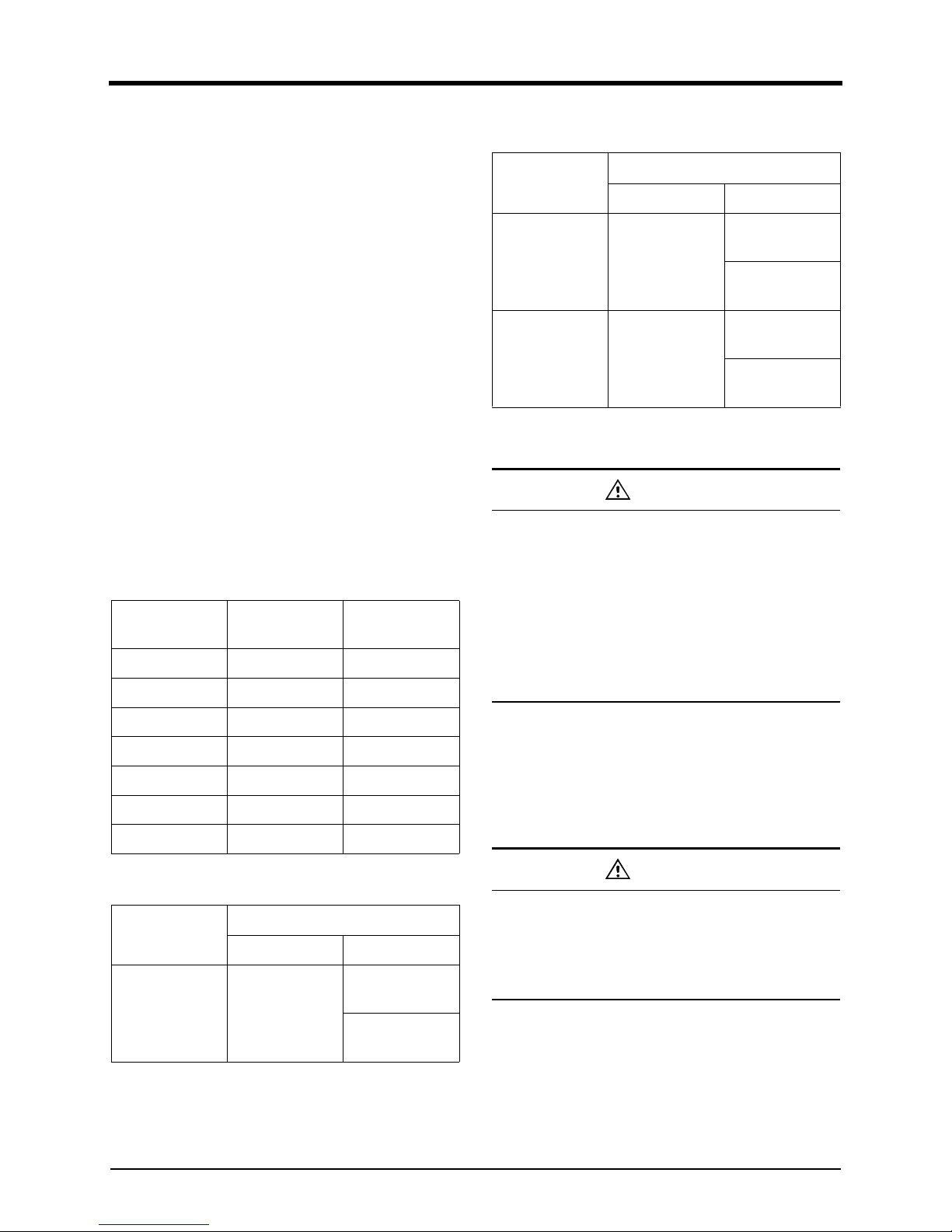
Coolant standards
We recommend you to inject the antifreeze about
40~50% of the entire coolant. The antifreeze prevents the
freezing and corrosion of the system, and increases the
boiling point of water. In winter, you may need to change
the amount of antifreeze per ambient temperature as
shown in the table below. The freezing point per anti-
freeze ratio shown in the table may differ slightly
depending on the antifreeze type. For more information,
see the specifications provided by the manufacturer.
Whenever you add coolant(water) to replenish the amount
reduced by engine operation, the antifreeze portion is
decreased. So, you need to increase the antifreeze level
to the proper level after replenishing the coolant.
• concentration of antifreeze during winter
Capacity of coolant
Checking the Coolant
1. For the engine coolant, you should use clean tap
water.
2. To the engine coolant add 40% of antifreeze,
and
3~5%
of additive(DCA4) to prevent corrosion.
3. Periodically check coolant to maintain the concentra-
tion of antifreeze and additives.
4. The engine cylinder liner is of a wet type which
specially requires good coolant flow.
5. You can check the concentration of antifreeze a
nd
cor
rosion inhibitor using the coolant test sheet.
Ambient tem-
perature (°C)
Coolant (°C)
Antifreeze (%)
Above -10 85 15
-10 80 20
-15 73 27
-20 67 33
-25 60 40
-30 56 44
-40 50 50
Engine Mode
Coolant capacity ( ℓ )
Inside engine With radiator
DP 158L About 20
About 79
(Air on 43°c)
About 90
(Air on 52°c)
DP180L About 21
About 91
(Air on 43°c)
About 114
(Air on 43°c)
DP 222L About 23
About 114
(Air on 43°c)
About 125
(Air on 52°c)
DANGER
If the radiator cap is opened to exchange or
replenish coolant while the engine is overheated, hot
water will spurt out and may cause serious burns.
If it is absolutely necessary to open the radiator cap
while the engine is overheated, wrap the radiator cap
with a cloth and slowly open the cap in two steps
until the steam pressure has been released from the
inside. After the steam pressure has been completely
released, remove the radiator cap.
DANGER
If you keep the antifreeze and corrosion inhibitor at
a proper level, you can prevent the corrosion of
engine effectively and keep the quality of the engine.
Be careful that, if managed improperly, it can give a
fatal impact on the coolant pump and cylinder liner.
Engine Mode
Coolant capacity ( ℓ )
Inside engine With radiator
4. Regular inspection
47
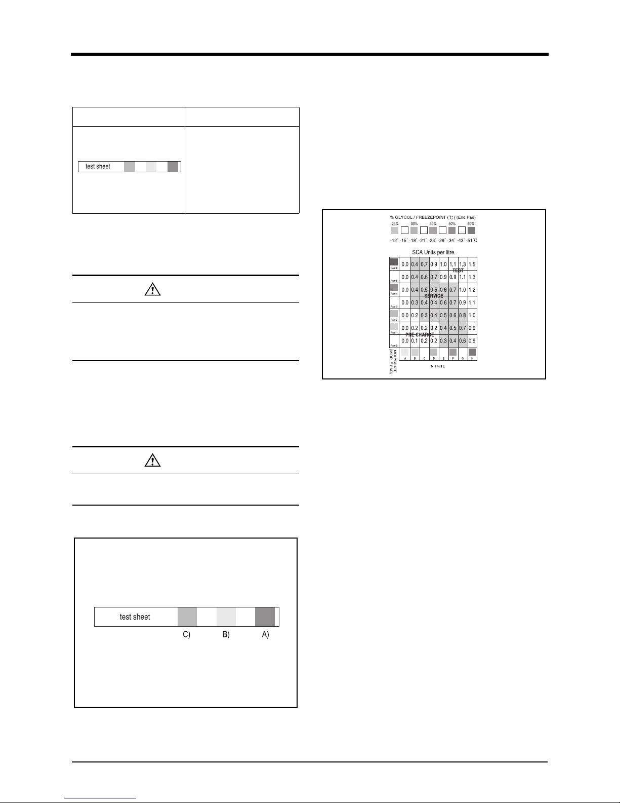
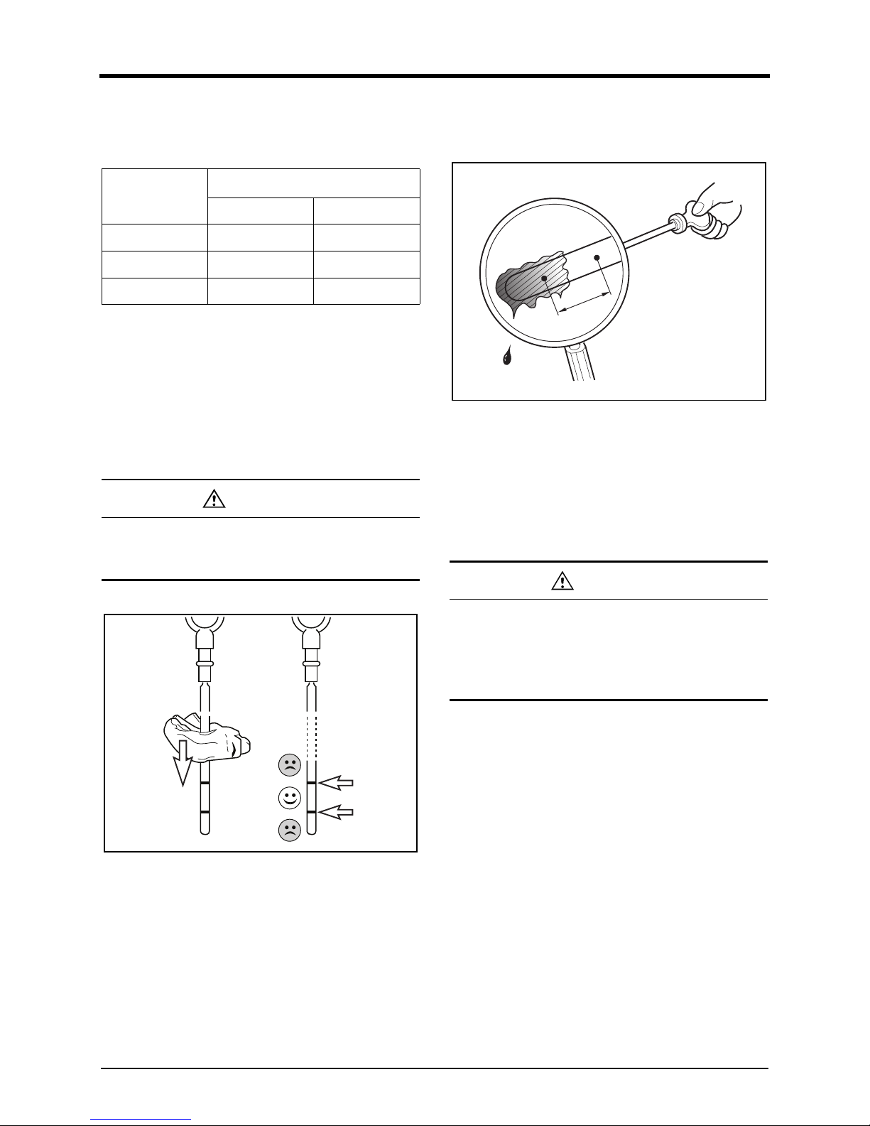
Measurement of Coolant Concentration
• Special Tools
The coolant concentration can be measured as follows.
1. If the engine coolant temperature is within a range of
10 ~ 55°C, drain the coolant and fill half a plastic cu
p
wi
th it.
2. Soak the test sheet in the coolant and take it out after
3 ~ 5 seconds. Shake the sheet to remove the
remaining coolant.
3. Wait for about 45 seconds until the test sheet
changes its color.
4. Check the color on test sheet.
EDL0213002A
1) Compare the color of part A on the test sheet to the
col
or of GLYCOL/FREEZEPOINT (End pad) of t
he
st
andard color table.
2) Compare the color of the test sheet (B) to the color
of MOLYBDATE (Middle pad) of the standard color
table.
3) Compare the color of the test sheet (C) to the color
of NITRITE of the standard color table.
5. Compare and confirm the parts with identical colors
on the test sheet and the standard color table.
EDL022154A
1) Compare the changed pink color part A of the test
sheet with the GLYOOL/FREEZEPOINT (End pad) of
the standard color table on top of the container and
confirm the concentration. The concentration indicati
on
has
to be within the color scope of 33~50%.
2) The state of additives for anticorrosion is shown
on
t
he point where the color of MOLYBDATE (Middl
e
pad)
on the standard color table (which is identical
with the Middle (B) of the test sheet) is crossed with
the color of NITRITE on the standard color tabl
e
(
which is identical with the (C) of the test sheet). It
should be maintained at the optimum range, in the
green section between 0.3 to 0.8.
Figure Product Number/Name
60.99901-0038 CC2602M
Coolant test sheet
CAUTION
When taking out a sample of coolant from the
supplementary tank, it is difficult to measure the
precise concentration. Always take out sample by
opening the drain plug of coolant.
CAUTION
Measurement time should not exceed 75 seconds.
The color changes as time passes.
C) B) A)
TESTTEST
SERVICESERVICE
PRE CHARGEPRE CHARGE
4. Regular inspection
48
3) If the measurement result is below 0.3, replenish anti-
corrosion additives (DCA4). If it is above 0.8 or, drai
n
a
little coolant and then add clean tap water to adjust
the concentration.
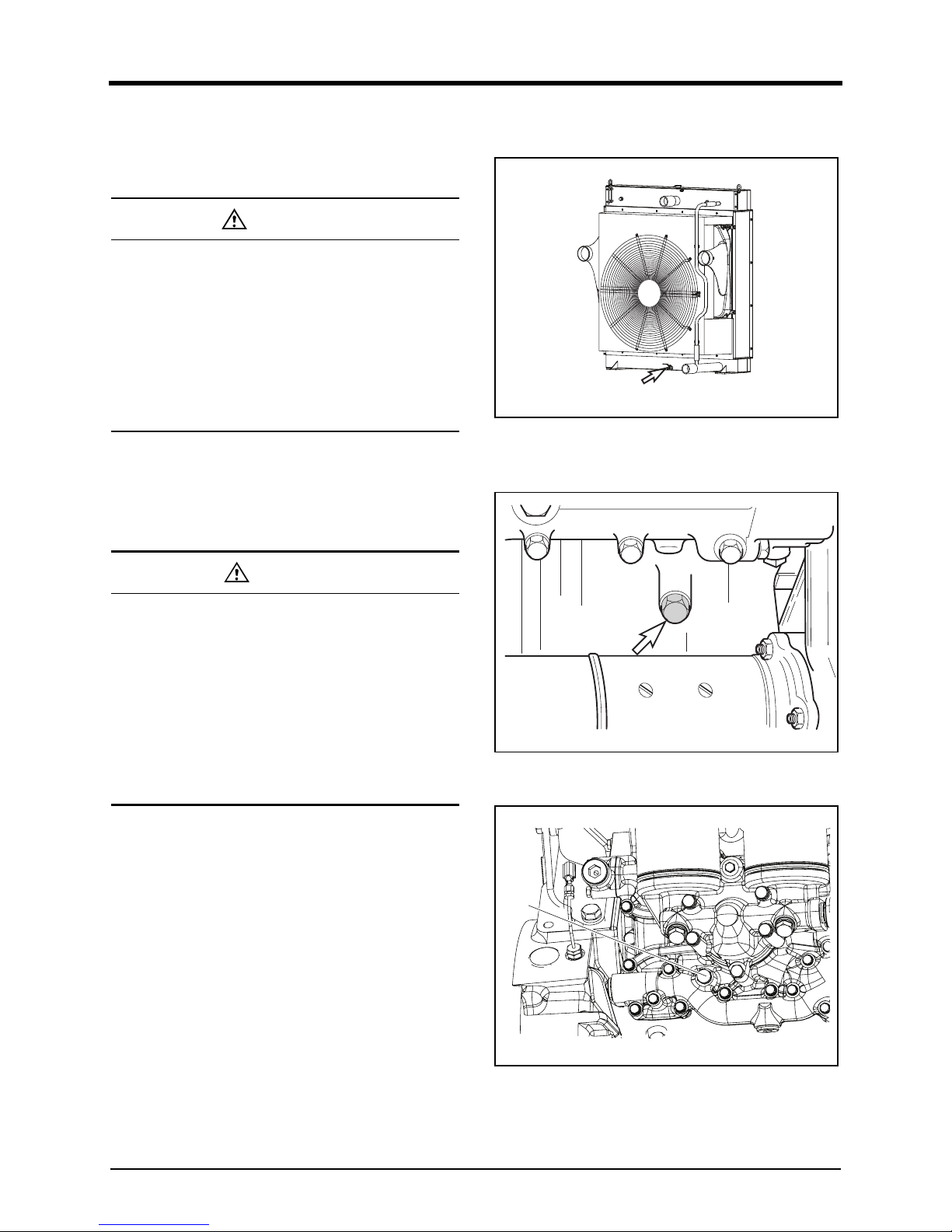
Discharging the coolant
The coolant can be discharged as follows.
1. Make sure that engine and radiator are cooled.
2. Open the radiator cap.
3. Loosen the drain valve which is located under t
he
r
adiator to discharge the coolant.
DV2213011A_E
4. Disassemble the coolant discharge plug of the cylinder
block, and discharge it to a container.
DV2213012A
5. Drain cooling water in the oil cooler.
DV2213167A
1) Loosen the drain plug(A) of the oil cooler cover and
t
hen drain cooling water.
CAUTION
• If the color on the test sheet does not match the
c
olor of the standard color table, find a middl
e
c
olor on the standard color table. For example, if
the color of (C) of the test sheet matches
D and
F
on the NITRITE of the standard color table,
select E.
• To prevent corrosion inside of the engine cooling
unit, drain the coolant and replace it with new
coolant once a year.
DANGER
• Never open the radiator cap while the engine is
overheated. If the radiator cap is opened whil
e
t
he engine is overheated, hot water will spurt out
and may cause serious burns. Open the radiator
cap after ensuring that the engine has b
een
cooled sufficiently.
• Mark and separately manage the containers for
storing coolant from beverage containers to avoid
confusion. If coolant is ingested, see a doctor
immediately.
Drain valve
A
4. Regular inspection
49
Charging the Coolant
1. Make sure that engine is coolant.
2. Open the radiator cap.
3. Put in the coolant slowly.
4. Be sure that the air is gone out from cooling system.
5. After checking the coolant level when the engine is
warmed up, replenish coolant if necessary.
Cleaning the cooling circuit
If the internal coolant circuit is contaminated by corrosion
or foreign substance, the cooling effect is reduced. The
resistance in the coolant circuit may damage the mechan-
ical seal of the coolant pump.
The negative impact on the cooling circuit may be caused
by use of improper antifreeze or corrosion inhibitor, or by
use of coolant without such ingredients. If the coolant
pump leaks or the coolant is severely contaminated within
short period of time (6 months) after start of using the
operation (e.g., the coolant color becomes muddy - prob-
ably brown, gray or black depending on the degree of
contamination), before removing the coolant pump, clean
the cooling system in the following way.
1. Discharge the coolant.
2. If you want to clean the cooling circuit swiftly, remo
ve
t
he thermostat.
3. Mix water and 1.5% of cleaning solution and fill t
he
cool
ing circuit with this liquid.
4. Load the engine. When the coolant temperatur
e
r
eaches 60°C, run the engine for about 15 minutes.
5. Discharge the cleansing solution.
6. Repeat the step 3 and 4 above.
7. Fill the cooling circuit with hot water.
8. While running the engine at idle speed for 30 minutes,
check if there is any leakage in the drain plug
and
cool
ant line. If the coolant is insufficient, replenish it.
DANGER
• Never open the radiator cap while the engine is
overheated. If the radiator cap is opened whil
e
t
he engine is overheated, hot water will spurt out
and may cause serious burns. Open the radiator
cap after ensuring that the engine has b
een
cooled sufficiently.
• Mark and separately manage the containers for
storing coolant from beverage containers to avoid
confusion. If coolant is ingested, see a doctor
immediately.
CAUTION
Be careful not to let foreign substances flow into the
engine when replenishing coolant.
DANGER
If the engine is hot, wrap the coolant pressure cap
with a cloth upon opening it so that the steam may
be discharged. This can prevent you from burning
by the hot steam coming out of the cap inlet.
CAUTION
• Do not mix antifreezes from different manufac-
turers.
• Do not mix the coolant with different concentra-
tions.
• Do not add antirust which is not recommende
d
by us.
• As insufficient coolant concentration may cause
corrosion or freezing, on the other hand,
an
e
xcessive concentration may degrade the coolin
g
p
erformance. Mix coolant with 40% antifree
ze and
3
~5% additives (DCA4) to prevent corrosion.
WARNING
Discard exchanged coolant according to the regula-
tions set forth by the relevant authorities. Disposing
of exchanged coolant into the ground, sewers,
drains, rivers, or the sea will cause serious environ-
mental pollution. Violation of regulations regarding
discard of coolant without observing the handling
regulations, will be punished.
CAUTION
Clean the cooling circuit regularly with cleansing
solution.
4. Regular inspection
50
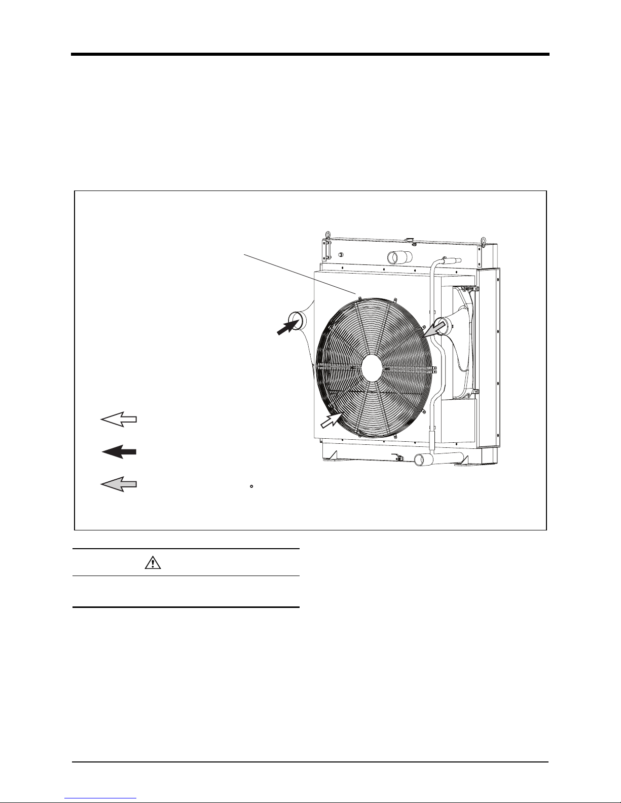
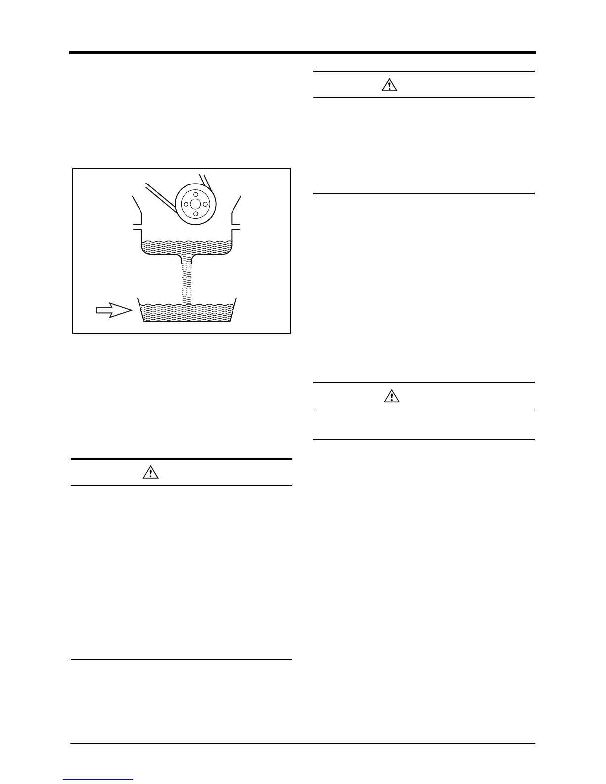
Inter cooler
The air cooler adopts an air cooling fan, which has suffi-
cient cooling capacity. The life and performance of an air
cooler greatly depends on the intake air conditions. Dirty
air may contaminate and clog the cooling pins. This
results in reduced engine power or engine failure. So,
always check the intake system for air leak, damage or
contamination of air filter.
DV2213205B
CAUTION
To keep the optimum performance of the air cooler,
clean it regularly.
Air/air intercooler
with downstream
radiator
(Combined radiator)
Cooling air
Hot charge air
from compressor
Recooled charge air
to intake pipe (max. 50 C)
4. Regular inspection
51
Lubrication system
General Information
Engine oil lubricates, cools, seals, prevents corrosion, and
cleans engines, enhancing engine performance and
extending the engine's lifetime. If a vehicle is continuously
driven while engine oil is insufficient, the moving parts of
the engine may get stuck, causing engine faults.
Engine oil should be checked through the oil level gauge
and replenished if required. Oil level should be checked
while the engine is stopped. To check the oil level,
turn off the engine while it is running and wait for 5 ~10
minutes to allow the engine oil to flow back into the oil
pan. The engine oil level should indicate between the
upper limit and the lower limit of the oil level gauge.
Engine oil should be periodically replaced based on the
regular inspection table and the oil filter and the cartridge
should be replaced as the engine oil is replaced.
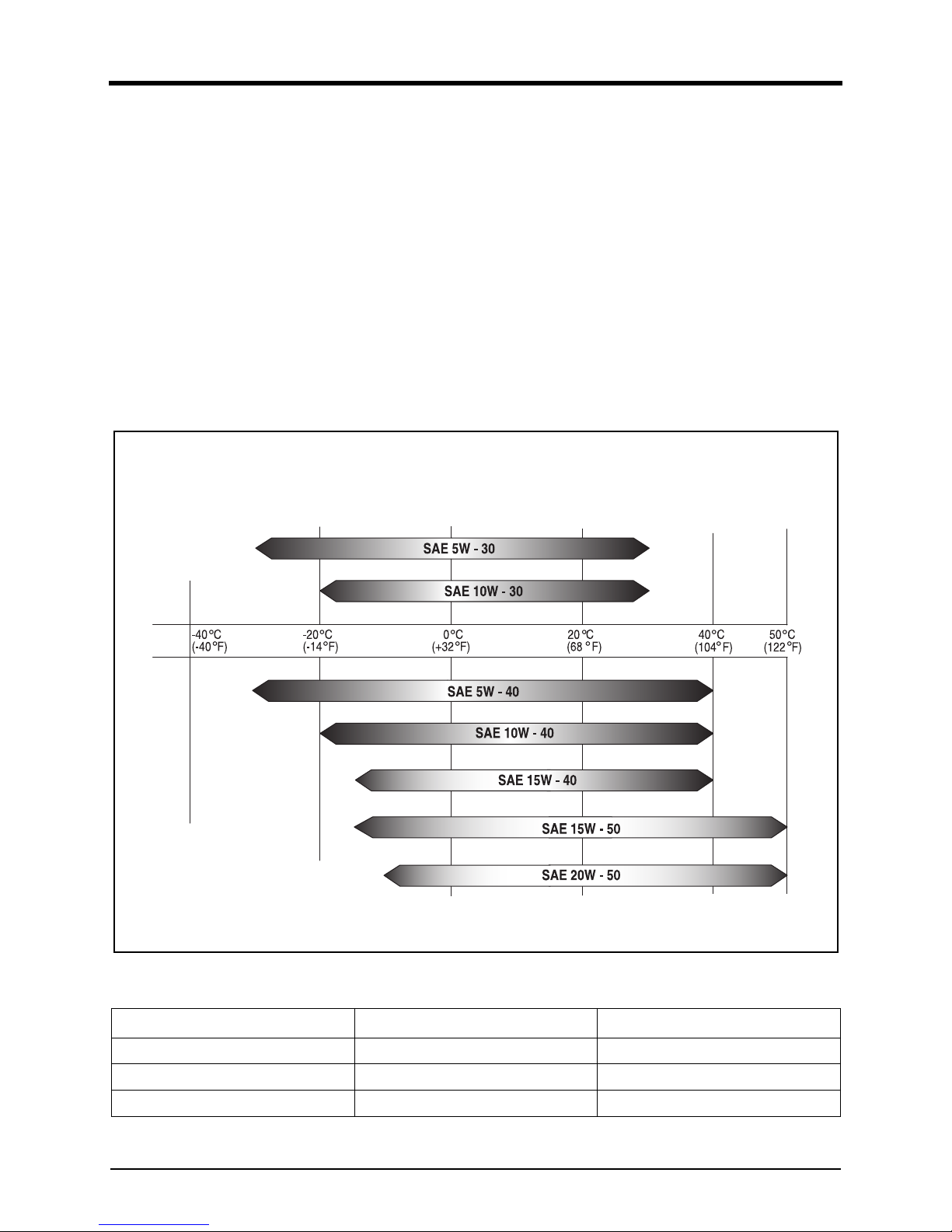
Engine oil standards
Use the specified engine oil suitable for the environment
and conditions of the site where the engine will be used.
EDL0213001A
Please use the engine oil which satisfies the following recommended specifications.
Note) Use of Doosan genuine engine oil is recommended.
Engine Model and Product Code SAE Classification Oil Class
DP 158L SAE 15W40 API CD or above
DP180L SAE 15W40 API CD or above
DP 222L SAE 15W40 API CD or above
Engine Oil Viscosity by temperature
Ambient
temperature
4. Regular inspection
52
Engine Oil Capacity
Please replenish the engine oil based on the following
recommended oil amount.
Checking the Engine Oil
Check the oil level everyday using an oil level gauge.
1. The oil level should be checked when the engine is
stopped and on an even level. If you started the
engine, wait for 5~10 minutes to allow the engine oil
to flow back into the oil pan.
2. Pull out the oil level gauge, and clean the indication
line of the oil level gauge with clean cloth.
DV2213163A
3. Insert the oil level gauge, and then pull it out to check
t
he engine oil level, viscosity, and contamination.
Replenish or replace the engine oil if required.
DV2213016A
1) Check the oil level everyday using an oil level gauge.
2) Check if the oil is smeared between the upper limit
(A)
and
the lower limit (B) of the oil level gauge.
3) If engine oil is smeared below the lower limit (B) or
not smeared on the gauge at all, replenish engine oil.
4) Check condition of engine oil. If it is polluted, replac
e
i
t with new oil.
Engine Model
Engine oil capacity ( ℓ )
Max. Min.
DP 158L 22 13
DP 180L 34 23
DP 222L 40 27
CAUTION
Cleaning the indication line of the oil level gauge
with dirty cloth allows the foreign substances to get
into the engine, causing damage to the engine.
Max
Min
CAUTION
• Do not fill the engine oil above the upper limit.
Exceeding the upper limit may damage th
e
engi
ne.
• Be careful not to let foreign substances flow into
the engine when replenishing engine oil.
A
B
4. Regular inspection
53
Replacement of Engine Oil
Check the oil level using an oil level gauge and replenish
it if required. Replace the engine oil in the following steps
when the engine is warm by running it.
1. Pull out the oil level gauge.
2. Open the drain plug of the oil pan to discharge the
engine oil from the container.
DV2213017A
3. After discharging the engine oil, assemble the drain
p
lug of ghe oil pan again.
4. Fill the engine oil into the cartridge of the oil filter.
5. Through the oil filler cap, fill the engine oil.
6. Idle the engine for several minutes so that the oil
circulate through the lubrication system.
7. Then, stop the engine, wait for about 10 minutes,
check the oil level, and fill the oil if required.
Replacement of Engine Filter
Check the oil pressure and leakage, and replace the oil
filter if required. Whenever replacing the oil, the oil filter
cartridge should be replaced with a new on.
1. Using an oil filter wrench, loosen the cartridge by
turning it counterclockwise.
2. Wipe the oil filter head and cartridge contact thor-
oughly, and make sure that the oil filter cartridge is
positioned properly.
3. Apply a little bit of oil to the o-ring area of t
he
car
tridge, assemble it until the O-ring surface ma
y
cont
act, and turn it 3/4 or 1 turn using a wrench to
keep it air-tight.
DANGER
• Prolonged and repeated contact of skin with
engine oil may lead to shrinking, dryness of ski
n
a
nd even cause dermatitis.
• Do not expose skin with exchanged engine oil for
a long period.
• Always wear work clothes and gloves.
• When skin is stained with engine oil, immediatel
y
w
ash it with water, soap or hand cleaners.
• Do not clean skin with gasoline, fuel, thinner, or
solvent.
• Apply a skin protective cream after cleaning from
oil.
• Do not put oil-stained gloves or cloth in pockets.
WARNING
Discard exchanged oil according to the regulations
set forth by the relevant authorities. Disposing of
discharged oil into the ground, sewers, drains,
rivers, or the sea will cause serious environmental
pollution. Violation of regulations regarding discard
of engine oil without observing the handling regula-
tions, will be punished.
CAUTION
When replacing the oil filter cartridge, be sure to use
the genuine part of Doosan.
4. Regular inspection
54
Fuel system
General Information
The fuel injection pump and nozzle are composed of very
sophisticated components with high precision. If fuel is
mixed with foreign substance, it may clock the nozzle or
the fuel injection pump components may be seized. So,
be sure to keep the fuel system clean all the time.
Fuel Standards
The quality of fuel is very important to satisfy the engine
performance, extension of engine life and the allowable
exhaust gas level. Doosan engine engine is designed to
use diesel fuel available in the local market. If you want
the optimum engine performance, select the proper fuel
referring to the fuel selection table below.
• Low Sulfur Diesel
Note) High sulphur content in diesel fuel Doosan diesel
engines can be operated with fuels whose sulphur
content is max. 0.05wt%. Fuels with a sulphur
content of > 0.05wt% are not permitted as they
result in increased corrosion and hence greatly
reduce the service life of engines. The oil change
intervals must be halves if the sulphur content is >
0.02wt%.
CAUTION
• Use clean, certified and qualified fuel only. Using
i
rregular or unspecified fuel may cause critical
damage and faults to the engine.
• Replenish fuel while the engine is stopped.
Fuel Ingredients Unit Standard Product
Specific Gravity (kg/lit) - 0.83
Flash Point
(°C)
>
40
47.8
Viscosity (40°C) (cSt) 1.955 2.459
Sulfur content (wt%) < 0.05 0.038
Cloud point
(°C)
--3
Pour Point
(°C)
< -17.5 -27.2
Low temperature filter clogging point
(°C)
< -12 -18
Color (ASTM) < 2.5 0.7
Carbon Residue (10%) Distillation residue (wt) (%) < 0.15 0.08
Total acid value (mg KOH/g) < 0.40 0.03
Copper corrosion (100°C, 3 hrs) < 1 1 - a
Ash content (wt) (%) < 0.01 0.001
Moisture and Precipitate (vol. %) < 0.01 0.005
Cetane Index >
45
52
Distillation test temperature
50% Distillation Point
(°C)
- 264.4
90% Distillation Point
(°C)
< 360 344.3
4. Regular inspection
55
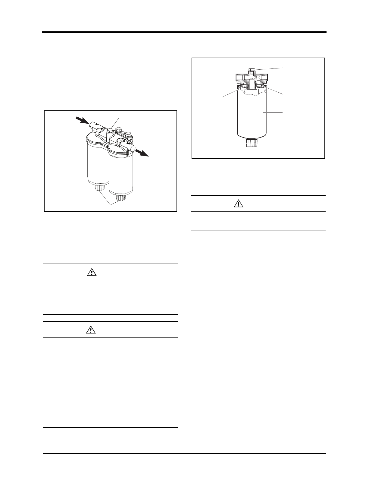
Water draining from fuel filter
An oil filter has two functions: oil filtering and water sepa-
ration.
1. the water separation function of the fuel filter
discharges water and sediment from the water
separator.
2. Stop the engine, and loosen the drain plug for water
separation manually.
DV2213164B
3. Turn the drain plug (A) for water separation counter-
clockwise 2~3times until water is drained. Drain t
he
wa
ter in the cartridge until fuel is discharged.
4. Tighten the drain plug for water separation by turning
it clockwise.
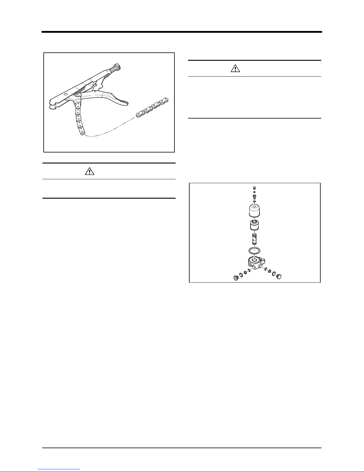
Replacing fuel filter
DV2213019A
1. Clean the area around the fuel filter head(3).
2. Disassemble the cartridge(2) by turning it counter-
clockwise with a fuel filter wrench.
3. Remove the fuel filter screw adapter seal ring(4).
4. Clean the gasket contact of the fuel filter head(3).
5. Check the position of the new cartridge adapter seal
ring(4).
6. Apply thin coat of clean oil to the O-ring(5) area of
the cartridge, and fill the cartridge with fuel.
7. Assemble the cartridge to the fuel filter head.
8. Tighten the cartridge with hand until the O-ri
ng
cont
acts the fuel filter head surface.
DANGER
Fuel may be drained when water is drained from the
fuel filter. Fuel is highly inflammable. Fire may occur
when you use fire near the engine when draining
water from the fuel filter.
CAUTION
• Do not tighten the plug excessively because it
may damage the screw.
• If you do not check the fuel filter regularly and
drain the water in the fuel filter, water flows into
the fuel system of the engine, causing seri
ous
failure in the fuel system, etc., and decrease in
or damage to the fuel filter performance. Inflow
of water to the fuel system may stop the engine.
• Use clean, specified, and qualified fuel only.
using irregular or unspecified fuel may result in
more water in the fuel filter.
A
B
CAUTION
Do not reuse the cartridge; replace them with new
ones.
1
5
2
3
4
6
4. Regular inspection
56
9. Turn it by 3/4 to 1 turn with a fuel filter wrench.
DV2213020A
Preventing fuel contamination
Most of the fuel contaminations encountered while using
the alternator engine are caused by water and propaga-
tion of microbes.
Usually, the contamination results from improper handling
of fuel. Propagation of microbes requires water contained
in the fuel. To prevent propagation of microbes, you have
to keep the water to the minimum level possible in the
storage tank.
Fuel injection pump
• Check the fuel injection pump housing, and replace it
if crack or damage is found.
• Check if the idle operaion and speed control lever’
s
s
ealing device was not removed.
• Chcek if the idling or speed control lever’s sealing li
ne
i
s not damaged.
• You should not modify the fuel injection pump if t
he
s
ealing line is damaged, such engine cannot receive
compensation.
• if the fuel injection pump is found abnormal, autho-
rized personnel should handle it.
• The adjustment and test of the fuel injection pump
must be conducted using a tester.
Cleaning the fuel pre-filter
The fuel pre-filter should be cleaned periodically through
disassembly. the fuel pre-filter is mounted individually for
easy maintenance. Open the cover of the pre-filter and
clean the element with compressed air first, and then
rinse it with diesel fuel to remove foreign substances.
DV2213021C
CAUTION
If you tighten the cartridge excessively, the screw
may be distorted or O-ring damaged.
CAUTION
If you separate the parts where the seal ring (copper
seal ring, rubber coating seal ring, etc.) is assem-
bled, you should replace the seal ring with a new
one. Otherwise, leakage may occur in the fuel filter
connections, preventing normal functioning.
4. Regular inspection
57
Air bleeding in the fuel circuit
When the engine stops due to replacement of fuel filter,
fuel injection pump or insufficient fuel, you should perform
air bleeding.
1. Loosen the air bleeding plug (B) on the fuel filter.
2. Operate the priming pump by hand to bleed air inside
the fuel circuit.
3. Operate the priming pump until the air is discharge
d
c
ompletely through visual checking.
DV2213164B
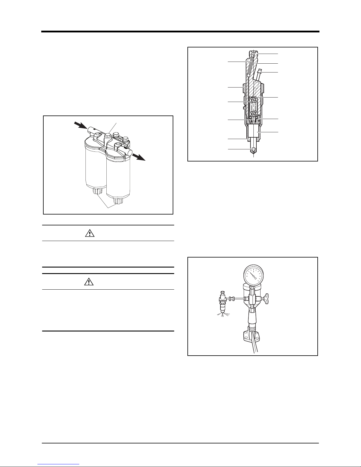
Injector maintenance
• The injectors are designed to spray the fuel delivered
b
y the injection pump directly into the spherical
combustion chamber in the piston crown.
• The injector consists of the nozzle and the nozzl
e
ho
lder.
• A copper gasket fitted to the injector ensures gas-tight
seating and good heat dissipation.
• The opening pressure of the nozzle is adjusted
by
m
eans of shims at the compression spring.
DV2213022A
Fuel injection nozzle
1. Install a nozzle to the nozzle tester.
DV2213023A
2. Check the fuel injection pressure. If the pressure does
not
satisfy the reference value, adjust the injecti
on
pr
essure of the nozzle using an adjustment shim.
DANGER
Fuel is highly inflammable. Fire may occur when you
use fire near the engine when air bleeding in the fuel
circuit from the priming pump.
CAUTION
If you separate the parts where the seal ring (copper
seal ring, rubber coating seal ring, etc.) is assem-
bled, you should replace the seal ring with a new
one. otherwise, leakage may occur in the fuel filter
connections, preventing normal functioning.
A
B
1. Rod type filter 7. Connect hole for fuel
delivery
2. Cap nut 8.Nozzle holder
3.Compression spring
9. Connect tube for overflow
4. Compression pin 10. Shim
5. Cap nut for fixed nozzle 11. Pin
6.
N
ozzle 12.Nozzle bush
8
7
9
5
4
3
11
12
6
10
2
1
4. Regular inspection
58
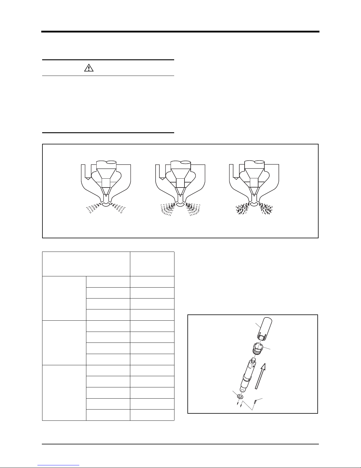
3. Check the nozzle spray status. If it is defective,
replace the nozzle.
DV2213165A
Removal of nozzle
1. Remove fuel injection pipe between nozzle holder and
i
njection pump.
2. Remove fuel return pipe.
3. loosen the Union screw(A) of nozzle holder with
Nozzle plug socket (EI.03004-0225)
4. Remove nozzle holder with sealing from the cylinder
head.
DV2213166B
CAUTION
• As the nozzle injection nozzle is designed to
operate under high pressure, you should handl
e
i
t with special care.
• Do not hold your hands under the fuel jet, as
there is a rise of injury. Do not inhale the atom-
ized oil fuel. If possible, work under an extractio
n
s
ystem.
abnormal abnormalnormal
Engine Model
Nozzle injec-
tion pressure
(Mpa)
DP158L
DP158LCS 28
DP158LCF 28
DP158LDS 28
DP158LDF 28
DP180L
DP180LBS 28
DP180LBF 28
DP180LAS 28
DP180LAF 28
DP222L
DP222LAS 28
DP222LBS 28
DP222LBF 28
DP222LCS 28
DP222LCF 28
Sealing
Dust seal
A
Nozzle plug socket
4. Regular inspection
59
Installation nozzle
1. Clean seat in cylinder head.
2. Insert nozzle holder with new gasket.
3. Tighten union nut with 12 kgf•m.
4. Install injection lines free of constraint. Install leak fuel
lines, screw delivery pipe at nozzle holder and at t
he
in
jection pump.
Note for cleaning nozzle
• Clean nozzle body externally from soot and carbon,
When cleaning several nozzles at the same time,
make sure nozzle bodies and needles are not mix
ed
u
p. Visually inspect needle and body.
• Cleaning is useless if the seat of the needle is
indented or the pintle is damaged and the nozzl
e
s
hould be replaced.
• Clean annular groove with scraper over full circumfer-
ence. Wash out dislodged carbon deposits and dirt.
• Scrape needle seat with cleaning cutter, Dip cutter in
test oil before use. The cutter can also be clampe
d
in
a lathe.
• Polish needle seat with wooden cleaning tool, prefer-
ably by chucking the needle in a lathe at the pintle
end.
• Clean the spray holes of nozzles by chucki
ng a
c
leaning needle of suitable diameter in the collect. If
the carbon deposits in the spray holes cannot
be
r
emoved by rotating and pressing, have the needl
e
p
roject only slightly from the collect and drive out t
he
c
arbon by lightly tapping on the tool.
• Before reassembly thoroughly wash nozzle body
and
needl
e in clean test oil.
• Hold the needle at the pintle end only ; to avoid corro-
sion do not touch the lapped surfaces of the needle
with you fingers.
• Thoroughly clean all other parts of the nozzle holder
with clean fuel.
• Check nozzle discharge pressure in nozzle tester. Th
e
edge-
type filter should not be pressed into the nozzl
e
hol
der by more than about 5mm. If this depth is
exceeded the injector must be replaced.
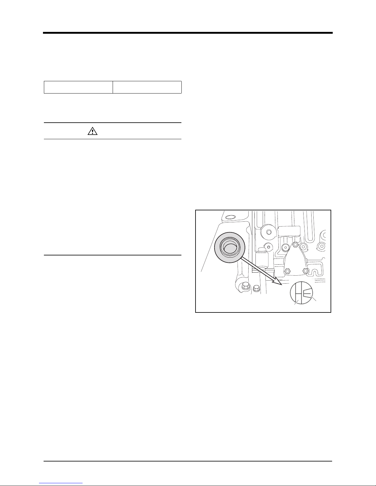
Checking the injection timing
1. Remove the plug screw on the flywheel housing
cover.
Note) Some cases are needed to remove cover
assembly.
2. Turn the crank pulley so that the mark on pointer
provided on injection pump coincides with matching
mark(FB) on the flange surface of the drive gear.
DV2213164A_K
Torque
12kgf·m
CAUTION
• The injection lines are designed for high oper-
ating pressure and should thus be handled with
particular core.
• When mounting the pipes to the engine take car
e
o
f good fitness.
• Do not bend pipes to permanent deformation.
(not for replacing the nozzles either)
• Do not mount any heavily bent pipes.
• Avoid bending the pipes at the ends by more
than 2 to 3 degrees.
• In case of faults in the injection system whic
h
m
ight have resulted in excessive operating pres-
sures, not only the failed part but also the injec-
tion line has to be replaced.
FB
Flange
Pointer
4. Regular inspection
60
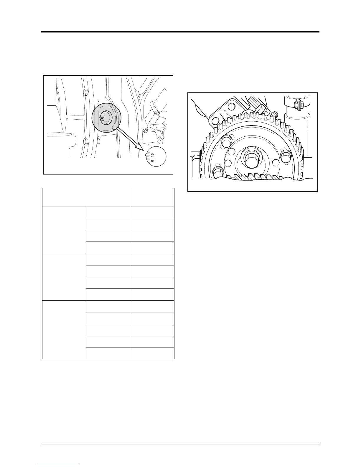
3. Check the injection timing degree whether the V-type
e
dge of the flywheel housing sight hole coincides with
the engine injection timing degree marked on t
he
f
lywheel corresponding to fuel delivery position.
DV2213165A_K
Adjusting injection timing
If upper pre-checked injection timing degree is wrong,
follow as below.
1. Loosen the fixing bolts(M8) of the injection pum
p
dr
iving gear in order to adjust the injection timing
slightly.
DV2213028A
2. Turn the crank pulley clockwise until V-groove of the
f
lywheel housing sight hole is aligned with the injecti
on
t
iming degree of the engine.
3. Coincide the mark on pointer provided in injecti
on
pum
p with the matching mark(FB) on the flang
e
sur
face of the drive gear by turning the flange in t
he
obl
onog holes of the drive gear.
4. Tighten the bolt(M8) to specified torque, (2.2 kgf·m)
not to move the drive gear.
5. After confirmation that fastening bolts are completely
tightened check the start point (injection timing
degree) of fuel delivery setting once more if not right
repeat it again as same as upper way.
Engine Model
Injection Tim-
ing (°)
DP158L
DP158LCS
23° ± 1°
DP158LCF
18° ± 1°
DP158LDS
23° ± 1°
DP158LDF
18° ± 1°
DP180L
DP180LBS
21° ± 1°
DP180LBF
19° ± 1°
DP180LAS
21° ± 1°
DP180LAF
19° ± 1°
DP222L
DP222LAS
21° ± 1°
DP222LBS
21° ± 1°
DP222LBF
19° ± 1°
DP222LCS
21° ± 1°
DP222
LCF
19° ± 1°
4. Regular inspection
61
Intake/exhaust system
General Information
The air filter purifies dust and foreign substances included
in the air and supplies clean air into the engine. The air
filter is directly related to engine lifetime, emissions, and
engine output. Please periodically check, clean, and
replace the air filter.
Air Filter
• Air cleaner is mounted on the engine to purify the air
for combustion.
• The intervals at which the air cleaner requires
servicing depend on the specific operating conditio
ns
e
ncountered.
• Clogged air filters may cause black smoke and re
duce
po
wer.
• A check should be made from time to time to see
that the fastening elements securing the air cleaner to
the intake manifold seal the connection tightly.
• Any ingress of unfiltered air is liable to cause a hi
gh
r
ate of cylinder and piston wear.
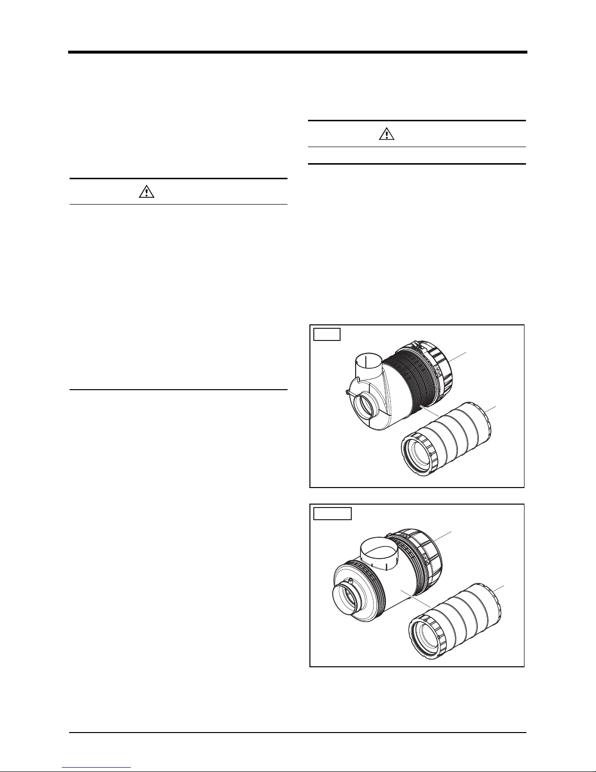
Disassembly of air filter
1. Empty the dust bucket periodically. The dust should
not exceed the half of the dust bucket capacity.
2. You can disassemble the dust bucket by removing tw
o
cl
amps. Remove the dust bucket cover and empty t
he
dust
inside.
3. Assemble the cover and dust bucket accurately with
care.
4. For easy alignment, the cover has dent and the dust
collector has a protrusion. Here is the position where
a filter is mounted horizontally, check the “TOP” mark
on the air filter canister.
DV2213029A
DV2213029A
CAUTION
• Do not operate the engine when the air filter is
separated from the engine.
• Use specified air filters only. Using unauthoriz
ed
o
r remanufactured air filters may result in critical
faults.
• Foreign substances in the engine m
ay cause
a
brasion inside the engine.
• Immediately exchange a damaged air filter wit
h a
new one.
• Be careful not to let foreign substances flow int
o
e
ngine or damage the air filter related electri
c
a
pparatus when replacing an air filter.
• Be careful not let dust inside when assemblin
g
th
e air filter.
DANGER
Allowed only when the engine is stopped.
1. Air cleaner ass'
y
2.
Air cleaner element
DV15
1
2
DV18/22
1
2
 Loading...