

Page 1

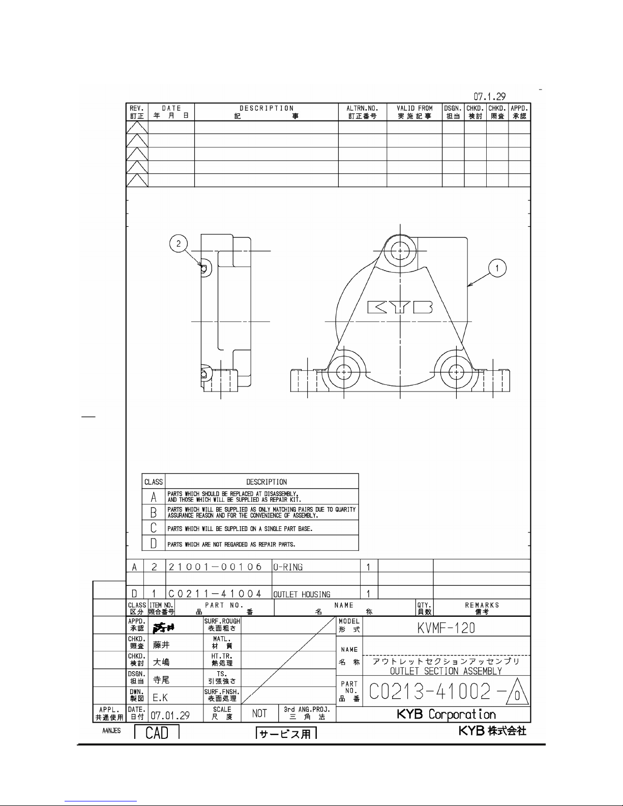
Vehicle System
Disassembly & Assembly
D35S-5, D40S-5, D45S-5, D50C-5, D55C-5
D40SC-5, D45SC-5, D50SC-5, D55SC-5
G35S-5, G40S-5, G45S-5, G50C-5, G55C-5
G40SC-5, G45SC-5, G50SC-5, G55SC-5
GC35S-5, GC40S-5, GC45S-5
GC50C-5, GC55C-5
SB4267E00
May. 2007
Page 2

Page 3
1
WARNING
Important Safety Information
Most accidents involving product operation, maintenance and repair are caused by failure to observe basic
safety rules or precautions. An accident can often be avoided by recognizing potentially hazardous situations
before an accident occurs. A person must be alert to potential hazards. This person should also have the
necessary training, skills and tools to perform these functions properly.
Read and understand all safety precautions and warnings before operating or performing lubrication,
maintenance and repair on this product.
Basic safety precautions are listed in the “Safety” section of the Service or Technical Manual. Additional safety
precautions are listed in the “Safety” section of the owner/operation/maintenance publication.
Specific safety warnings for all these publications are provided in the description of operations where hazards
exist. WARNING labels have also been put on the product to provide instructions and to identify specific
hazards. If these hazard warnings are not heeded, bodily injury or death could occur to you or other persons.
Warnings in this publication and on the product labels are identified by the following symbol.
Improper operation, lubrication, maintenance or repair of this product can be dangerous and could result in
injury or death.
Do not operate or perform any lubrication, maintenance or repair on this product, until you have read and
understood the operation, lubrication, maintenance and repair information.
Operations that may cause product damage are identified by NOTICE labels on the product and in this
publication.
DOOSAN cannot anticipate every possible circumstance that might involve a potential hazard. The warnings
in this publication and on the product are therefore not all inclusive. If a tool, procedure, work method or
operating technique not specifically recommended by DOOSAN is used, you must satisfy yourself that it is
safe for you and others. You should also ensure that the product will not be damaged or made unsafe by the
operation, lubrication, maintenance or repair procedures you choose.
The information, specifications, and illustrations in this publication are on the basis of information available at
the time it was written. The specifications, torques, pressures, measurements, adjustments, illustrations, and
other items can change at any time. These changes can affect the service given to the product. Obtain the
complete and most current information before starting any job. DOOSAN dealers have the most current
information available.
Page 4

Page 5

Vehicle Systems Index 3
Index
Disassembly & Assembly....................... 5
Hood (with seat) .................................................... 5
Overhead Guard.................................................... 6
Tilt Cylinders ......................................................... 7
Secondary Lift Cylinders........................................ 9
Primary Lift Cylinder ............................................ 12
Hydraulic Control Value ....................................... 15
Washing .............................................................. 17
Inspection............................................................ 17
Assembling.......................................................... 18
Relief Valve Maintenance .................................... 20
Steering Wheel .................................................... 29
Steering Unit ....................................................... 30
Brake Hydraulic Booster ...................................... 39
Tie Rods.............................................................. 43
Steering Knuckles, Kingpins, And Bearings ....... 44
Steer Axle............................................................ 45
Steering Cylinder ................................................. 46
Tires And Rims (Steer)........................................ 48
Hydraulic Control Valves...................................... 49
Hydraulic Pump ................................................... 50
General Instruction .............................................. 51
Disassembly Process .......................................... 51
Counterweight ..................................................... 56
Hydraulic Oil Filter Assembly............................... 57
Drive Axle and T/M .............................................. 57
Engine................................................................. 58
Disconnect batteries before performance of any
service work.
WARNING
Page 6

Page 7
Vehicle Systems Disassembly & Assembly 5
1
Disassembly & Assembly
Hood (with seat)
Remove & Install Hood (with seat)
Assembly
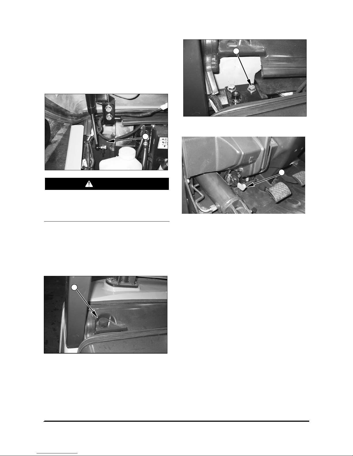
The hood and seat assembly can fall when nut
(1) is removed from the support cylinder rod. To
avoid personal injury, support the seat and hood
assembly before removing nut (1).
1. Raise the hood. Support the hood with a hoist.
2. Remove nut (1) from the support cylinder.
Remove the cylinder rod from the bracket.
3. Lower the hood.
4. Remove the bolts (2) from the cover. Remove
cover.
5. Remove the washers and four bolts (3).
6. Release latch (4). Use the hoist to remove hood
and seat assembly. The hood and seat assembly
weighs approximately 52 kg (115 lb).
7. Install the hood and seat assembly in the reverse
order of removal.
WARNING
2
3
4
Page 8
Vehicle Systems Disassembly & Assembly 6
Overhead Guard
Remove & Install Overhead Guard
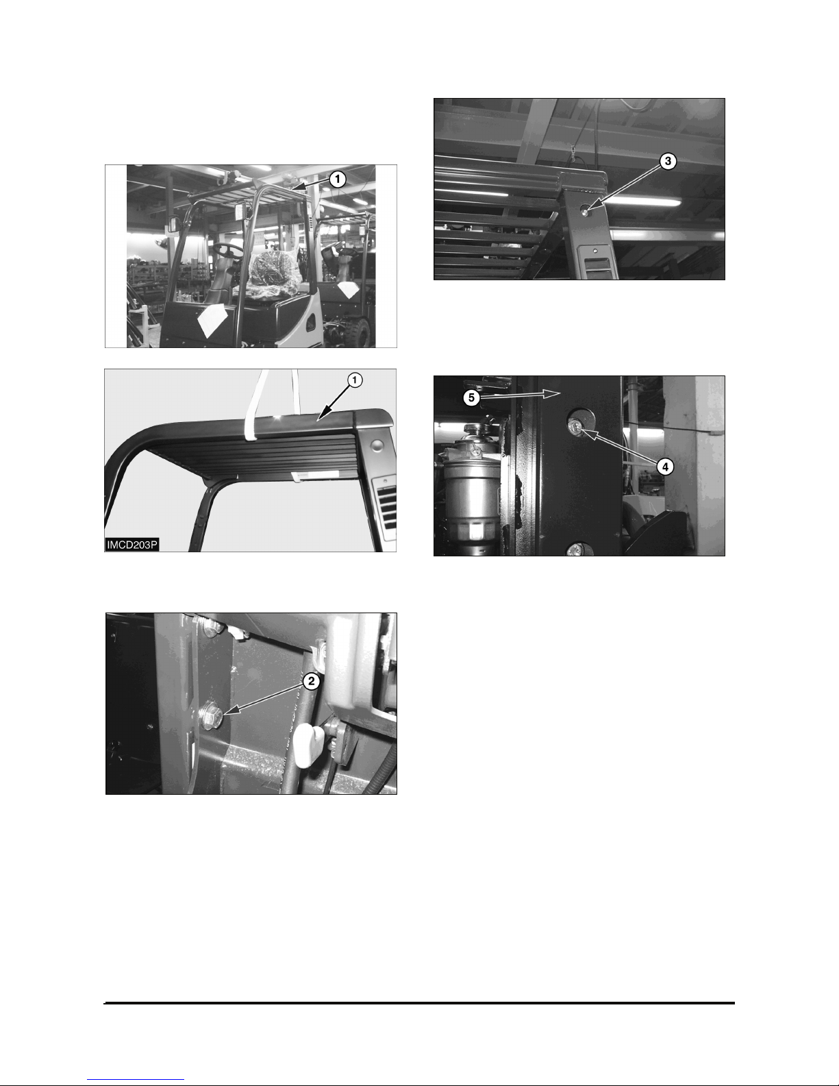
1. Support overhead guard (1) with lifting straps and
a hoist.
2. Remove the washers, nuts, and two bolts (2).
3. Remove the washers, nuts, and two bolts (3).
4. Remove front overhead guard (1), Front overhead
guard (1) weighs approximately 30 kg (66 lb).
5. Remove the washers, nuts, and four bolts (4).
6. Remove rear Leg (5).
7. Install front overhead guard (1) and rear leg (5) in
the reverse order of removal.
Page 9
Vehicle Systems Disassembly & Assembly 7
Tilt Cylinders
Remove & Install Tilt Cylinders
NOTE: The procedure for removing and installing
the tilt cylinders is the same for both cylinders.
If both tilt cylinders are removed at the same
time the mast can fall. To avoid possible
personal injury, make sure the mast is securely
held in place or supported by a hoist before
removing the tilt cylinders.
To prevent personal injury, move the control
levers backward and forward to release any
pressure in hydraulic system. Slowly loosen the
cap of the hydraulic tank to release any pressure
in the tank. Be cautious of hot hydraulic oil when
any lines are disconnected in the hydraulic
system.
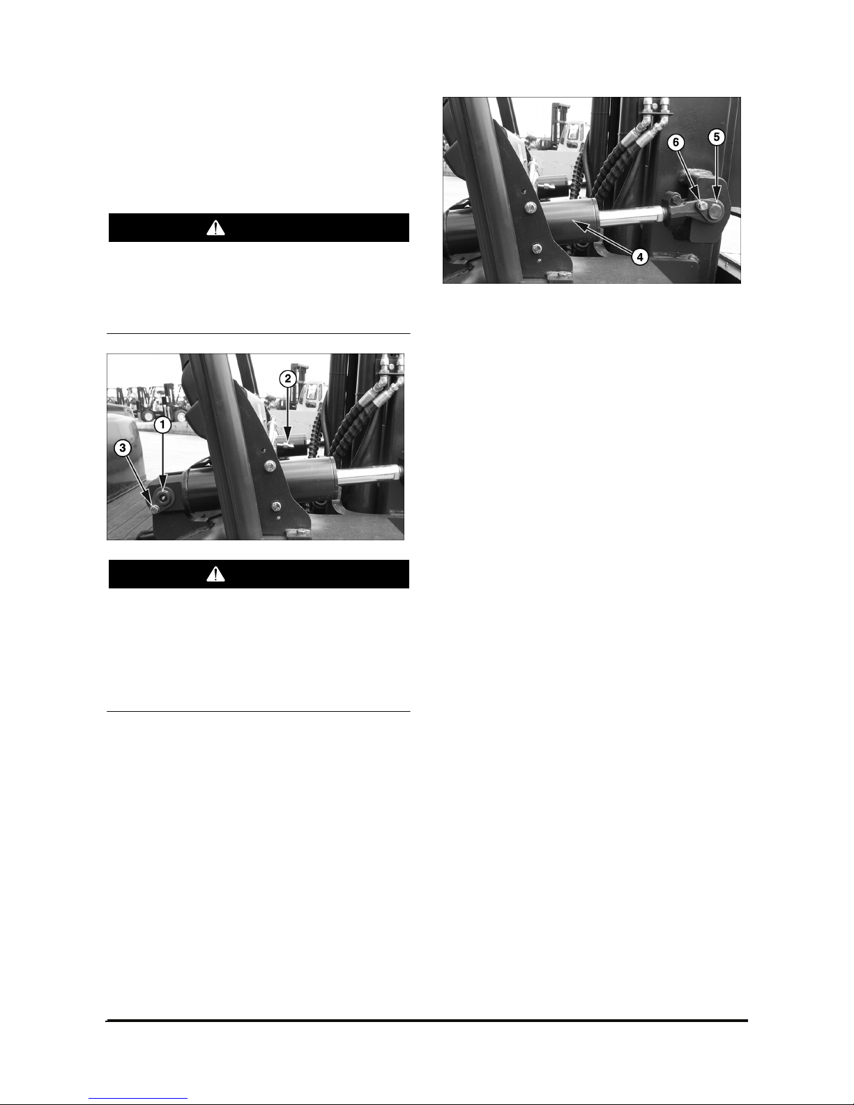
1. Disconnect elbow (2). Remove retainer bolt (3)
and pin (1).
2. Remove retainer bolt (6) from pin (5). Remove pin
(5).
3. Remove tilt cylinder (4).
4. Install the tilt cylinder in the reverse order of
removal.
WARNING
WARNING
Page 10
Vehicle Systems Disassembly & Assembly 8
Disassemble & Assemble Tilt Cylinders
Start By:
a. Remove tilt cylinder.
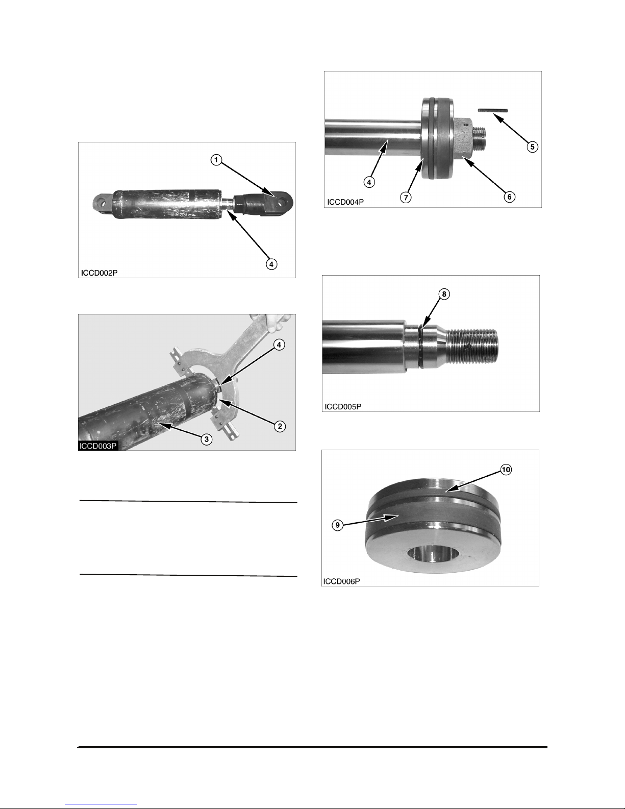
1. Remove eye (1) from the rod assembly (4).
2. Remove rod cover (2) from the cylinder tube (3)
using a spanner wrench.
NOTICE
Use extra care not to damage the highly finished
surface of the cylinder rod and the bore of the
clylinder tube during disassembly and assembly of
the tilt cylinder.
3. Remove rod assembly (4) from the cylinder body.
4. Remove pin (5) inside hole and nut (6) from the
cylinder rod (4).
5. Remove piston (7) from the cylinder rod.
6. Remove O-ring seal (8) from the cylinder rod.
7. Remove wear ring (9) and slipper seal (10) from
the piston.
Page 11
Vehicle Systems Disassembly & Assembly 9
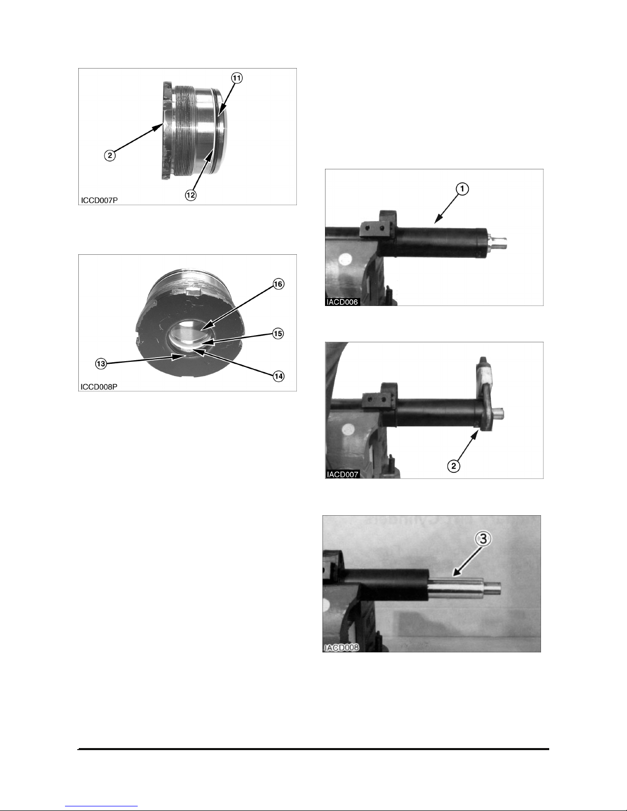
8. Remove O-ring seal (11) and backup ring (12)
from the rod cover (2).
9. Remove wiper seal (13), backup ring (14), Upacking (15) and DU-bush (16) from the rod cover.
NOTE: Assemble the tilt cylinder in the reverse
order of disassembly.
Secondary Lift Cylinders
Disassemble Secondary Lift Cylinders
Start By :
a. Remove secondary lift cylinders.
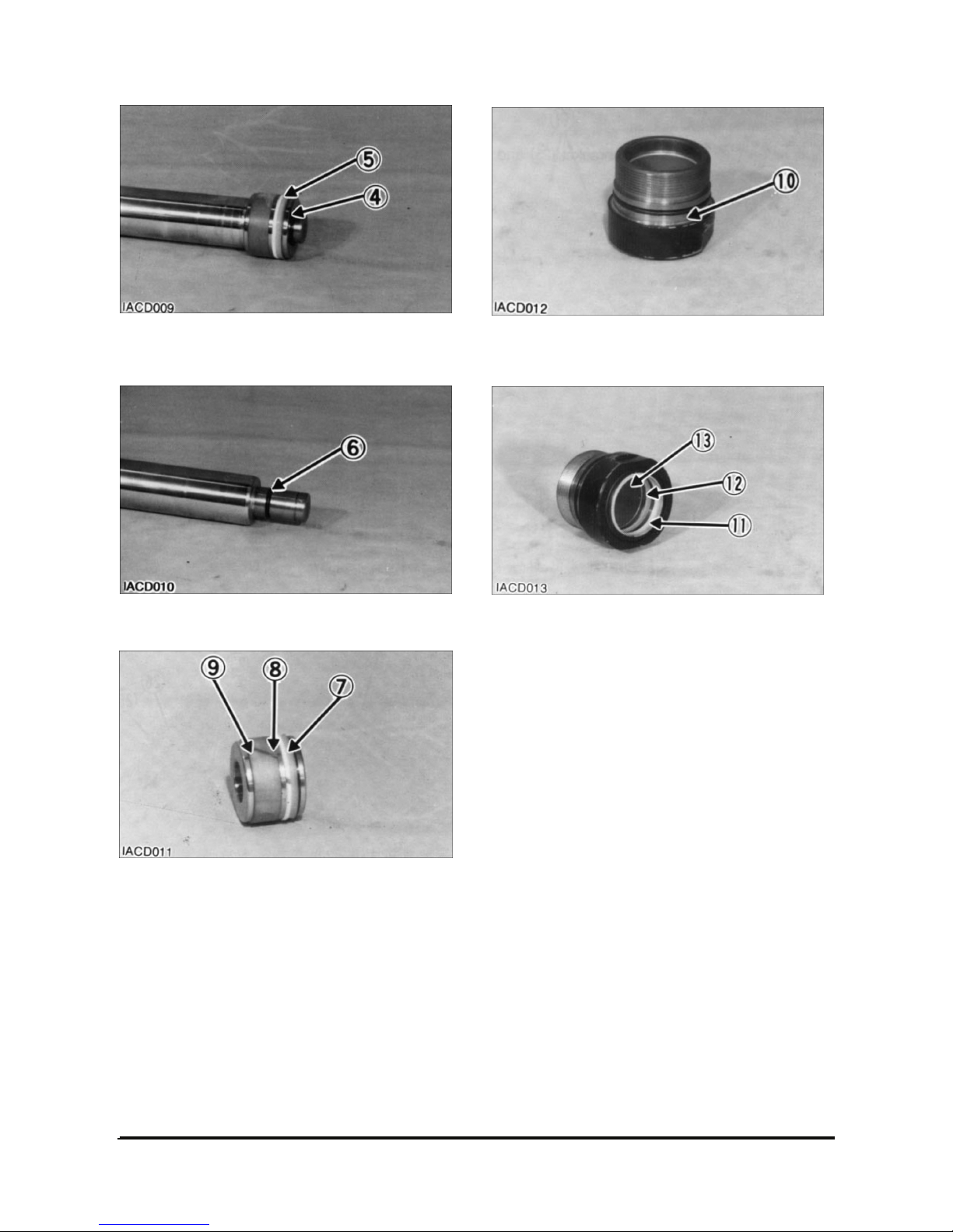
1. Put secondary lift cylinder (1) in position as shown.
2. Remove head assembly (2) with tool.
3. Remove rod (3) from the cylinder body.
Page 12
Vehicle Systems Disassembly & Assembly 10
4. Remove retaining ring (4) and piston (5) from the
cylinder rod.
5. Remove O-ring seal (6) from the cylinder rod.
6. Remove O-ring seal (7), back-up ring (8) and seal
(9) from the piston.
7. Remove O-ring seal (10) from the head assembly.
8. Remove wiper seal (11), seal (12) and bush (13)
from the head assembly.
Page 13
Vehicle Systems Disassembly & Assembly 11
Assemble Secondary Lift Cylinders
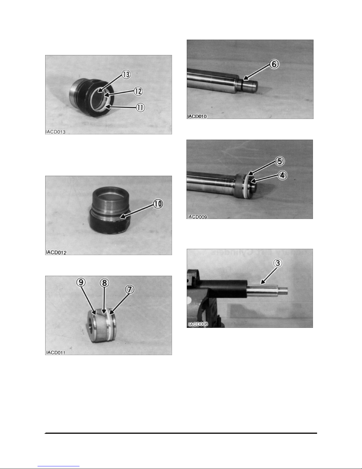
1. Install bush (13) and seal (12).
2. Install wiper seal (11). Install the seal with the lip
toward the outside.
3. Install O-ring seal (10) onto the head assembly.
4. Install seal (9), back-up ring (8) and O-ring seal
(7) on the piston.
5. Install O-ring seal (6) on the cylinder rod.
6. Install piston (5) and retaining ring (4) on the
cylinder rod.
7. Install cylinder rod (3) in the cylinder body.
Page 14
Vehicle Systems Disassembly & Assembly 12
8. Install head assembly (2) on the cylinder rod and
tighten using tool.
End By :
a. Install secondary lift cylinders.
Primary Lift Cylinder
Remove & Install Primary Lift Cylinder
Start By :
a. Remove carriage.
To prevent personal injury, move the control
levers backward and forward to release any
pressure in hydraulic system. Slowly loosen the
cap of the hydraulic tank to release any pressure
in the tank. Be cautious of hot hydraulic oil when
any lines are disconnected in the hydraulic
system.
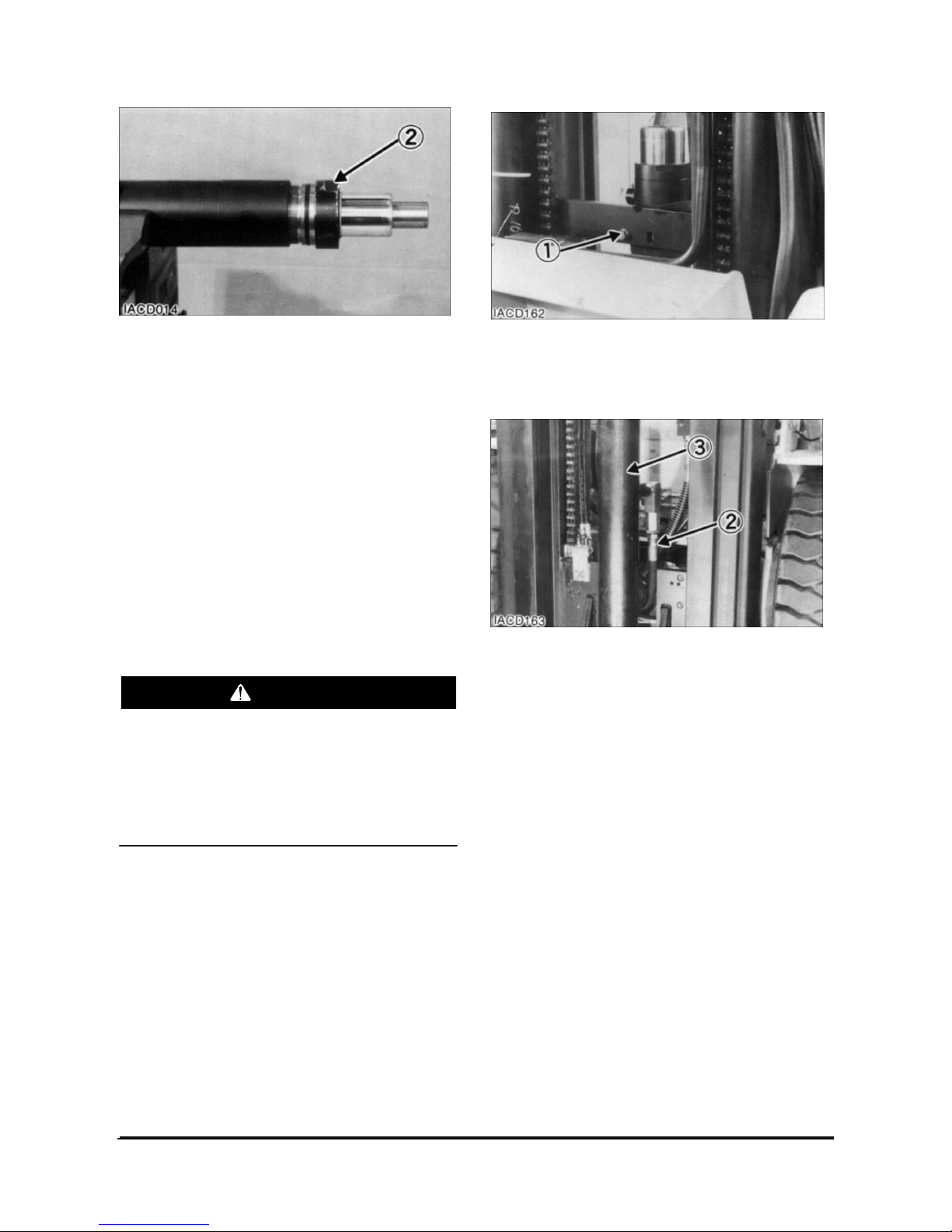
1. Fasten nylon straps and hoist to the primary lift
cylinder.
2. Remove bolt (1).
3. Pull the cylinder out far enough to disconnect
hydraulic hose (2). Remove primary lift cylinder
(3).
4. Install primary lift cylinder (3) in the reverse order
of removal.
End By :
a. Install carriage.
WARNING
Page 15
Vehicle Systems Disassembly & Assembly 13
Disassemble Primary Lift Cylinder
Start By :
a. Remove primary lift cylinder.
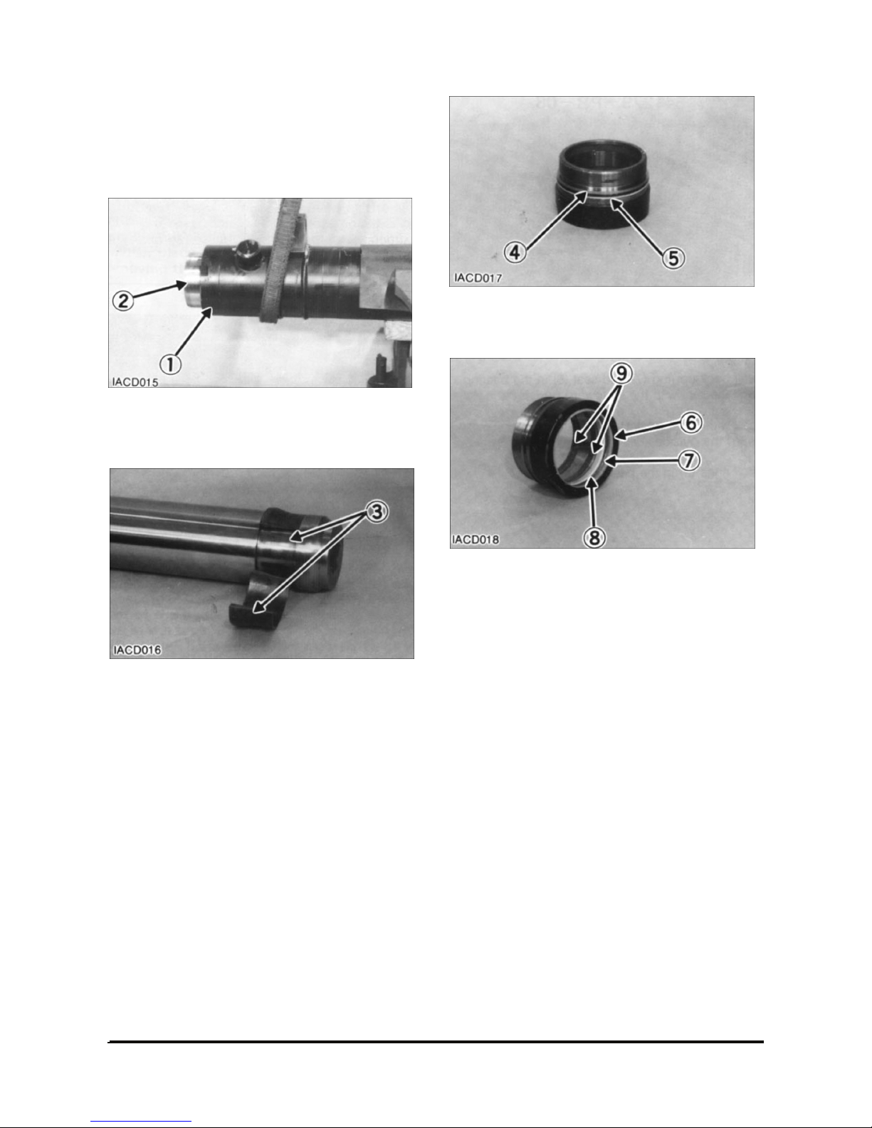
1. Remove bearing (1).
2. Remove rod (2) from the cylinder body.
3. Remove split rings (3) from the cylinder rod.
4. Remove O-ring seal (4) and back-up ring (5) from
the bearing.
5. Remove wiper seal (6), back-up ring (7), seal (8)
and rings (9) from the bearing.
Page 16
Vehicle Systems Disassembly & Assembly 14
Assemble Primary Lift Cylinder
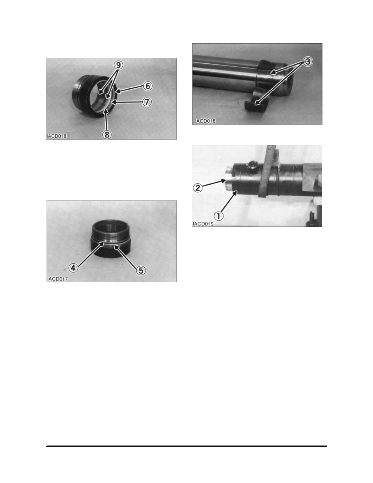
1. Install back-up ring (7) and seal (8) in the bearing.
Install the seal with the lip toward the inside.
2. Install wiper seal (6). Install the seal with the lip
toward the outside.
3. Install rings (9) in the bearing.
NOTE: Install the back-up ring with the curved side
contacting the O-ring seal.
4. Install the back-up ring (5) and O-ring seal (4) on
the bearing.
5. Install split rings (3) on the cylinder.
6. Install cylinder rod (2) in the cylinder body.
7. Install bearing (1) on the cylinder body. Tighten
the bearing (1).
End By :
a. Install primary lift cylinder.
Page 17
Vehicle Systems Disassembly & Assembly 15
Hydraulic Control Value
Disassembling
Keep following precautions for disassembling.
1. The main equipment has to be leveled, with all
the working units grounded, engine stopped, and
the actuator has to be depressurized. If
disassemble the actuator while it is pressurized,
high pressure oil or part may ejected out which is
very dangerous.
2. Release the air pressure in tank(for pressurized
tanks)
3. Clean up the surroundings of the part to be
disassembled, and take care that foreign matter
does not enter the valve.
4. Mark the disassembled parts or arrange them on
work bench in the order of assembly in order not
to confuse the order of assembling.
5. Replace all the seals(O-rings, back-up rings)
which were disassembled with new seals.
6. Since the spool is matched with the valve housing
by clearance control, it is not replaceable for
quality. Protect it from impact of falling down.
7. Protect the sealing faces of the fitting surfaces in
all sections from impact or scratch.
8. In order to minimize internal leak, the clearance of
spool is kept as small as possible. Disassembling
and assembling the spool may deform the spool.
Therefore, full assembly replacement, when
necessary, is recommended.
Refer to the attached Parts List for the dimensions
and torques of the screws and plugs related with the
disassembling.
Disassembling Valve Assembly
The assembling number shall be in compliance with
the attached Assembly Parts List: Representative
Parts No. C0240-41001.
1. Place the valve assembly on level work table, with
the mounting side down. Remove the nuts(1) and
(3) for the tie rod, at the end of the outlet section.
2. Slowly remove each spool section assembly in
the reverse order as in the outlet section.
Take care not to lose poppet, springs, or o-rings in
the fitting face of each section.
3. Remove the tie rods (2) & (4) from the inlet
section assembly.
Disassembling the Inlet Section
Assembly
The combination number shall be in accordance
with the attached Part List No. C0213-41001.
Fix the unit on the vise softly, covering the fitting
face of the inlet section assembly to prevent
damage.
1. Remove socket head bolt(14), remove cap(13),
and remove the spool(2) in sub-assembly state
from the inlet housing(1). The seal plate(5),
wiper(4), and O-ring(3) on the cap(13) side have
to be remain affixed to the spool(2)
【Cautions for Removing Spool 】
When removing the spool, take it out correctly to
prevent dent or scratch. Dent or scratch may harm
the housing hole when removing the spool, or may
make it impossible to reinsert the spool, or may
cause malfunction even able to be inserted. Each
spool has to be marked and arranged on work
bench, etc., to prevent confusion in reassembling. If
assembled wrong, the actuator will fail to operate
properly, which may cause serious danger.
【Fig. 2 – 1 】
Page 18
Vehicle Systems Disassembly & Assembly 16
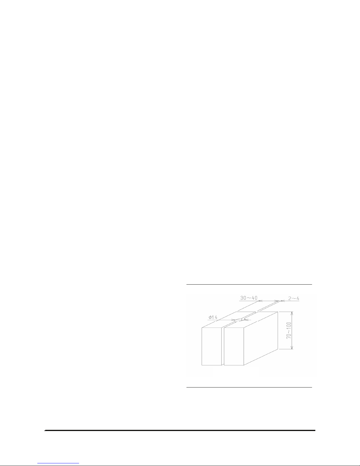
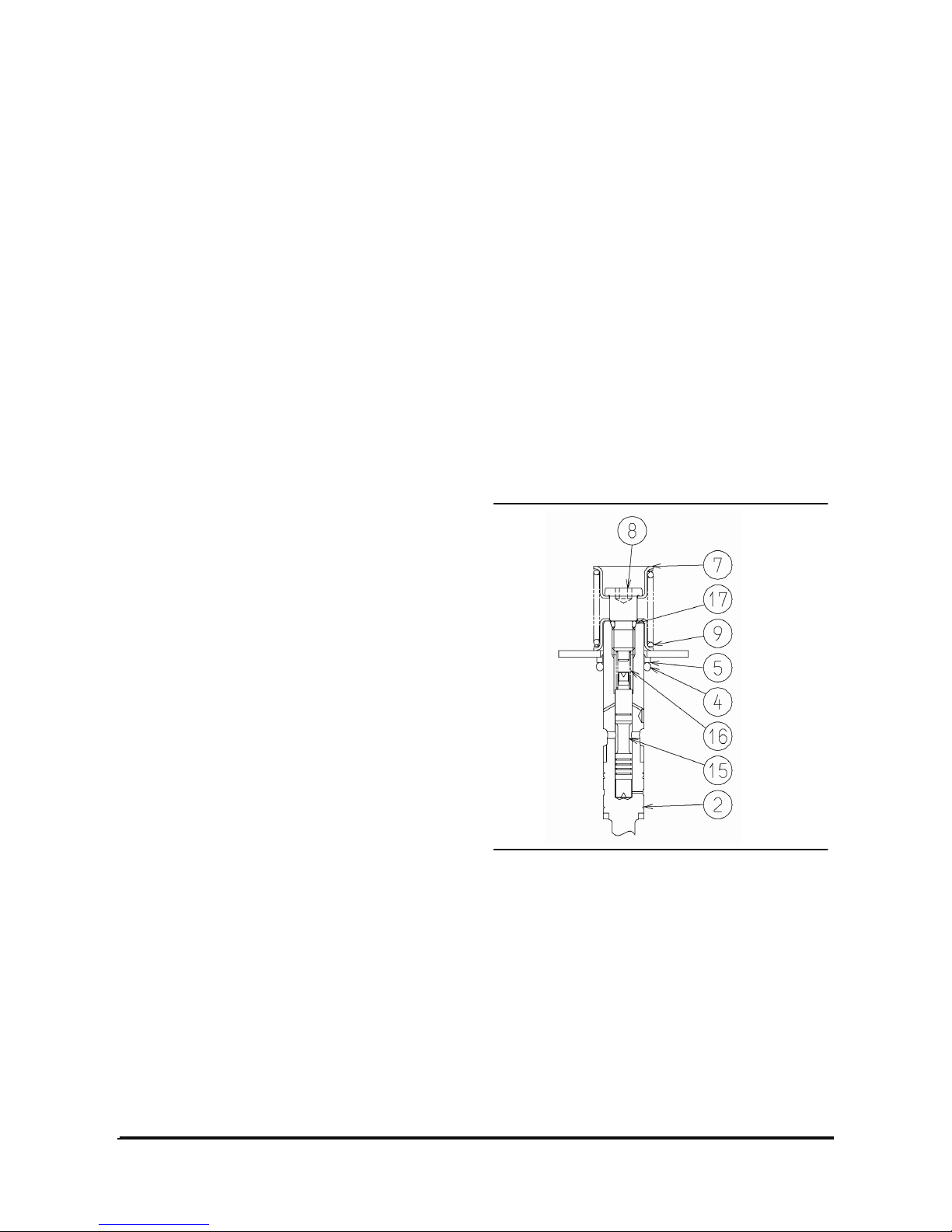
2. Hold the spool (2) on a vise by inserting rigid
wood pieces(Fig. 2-1) etc. to prevent damage on
the surface. Remove the cap screw(11),
disassemble spring seat(7) and spring(6), and
remove wiper(4) and O-ring(3). At this time, take
care that cap screw or other parts are not ejected
out by the spring force.
3. Remove the screw(15) on the spool head, remove
the seal plate(5), wiper(4) and O-ring(3).
4. Unscrew and remove the solenoid valve (24),
remove spring(22) and poppet(21).
5. Take off plug(18), and remove spring(17) and
poppet(16).
6. Unscrew the lock nut on the shut-of valve(20).
Turn the set screw by 1 or 2 turns and take it off
inwardly, and take out the main body of the shutoff valve.
7. Remove the socket head bolt(40), take out the
solenoid(38). Since an O-ring is mounted on the
in-low part of the solenoid providing large friction
force, do not apply excessive force to twist it.
Remove shuttle(36) and spring(37) from inside to
outside.
8. Unscrew the two relief valve assemblies(41) and
remove them from the assembly.
Though the two valves are identical in appearance,
however, since the pressure settings for the main
relief and second relief valves are different, mark
the two relief valves for distinguish them.
【Cautions for Disassembling the Relief Valve】
In principle, the relief valve has to be replaced in
assembly unit. Therefore, do not disassemble it
except when necessary. If it is necessary to
disassemble, refer to the Relief Valve Maintenance
Manual. Mark each part for identification in
assembling.
9. Take out plug(52), remove spring(51) and
spool(50).
10. Take out plug(30) and remove spool(26) and
spring(27) in assembly state.
Hold the sub-assembled spool(26) with a vise
using rigid wood pieces(Fig. 2-1) to prevent
damage on spool surface. Take out plug(29) and
remove the check valve(28) from inside.
11. Take out plug(34) and remove spring(33) and
poppet assembly(32).
Then, remove the main poppet from the poppet
assembly(32).
The poppet assembly was described as the
unload valve in the Operation Section earlier.
12. Take out the two plugs (42) and (59).
These three plugs are only for open/close,
without internal sub-parts. Therefore, do not
disassemble them except when necessary.
13. Finally, remove the O-rings and wipers on each
disassembled part.
Disassembling the Spool Section
Assembly for Tilting
The combination No. shall be in accordance with the
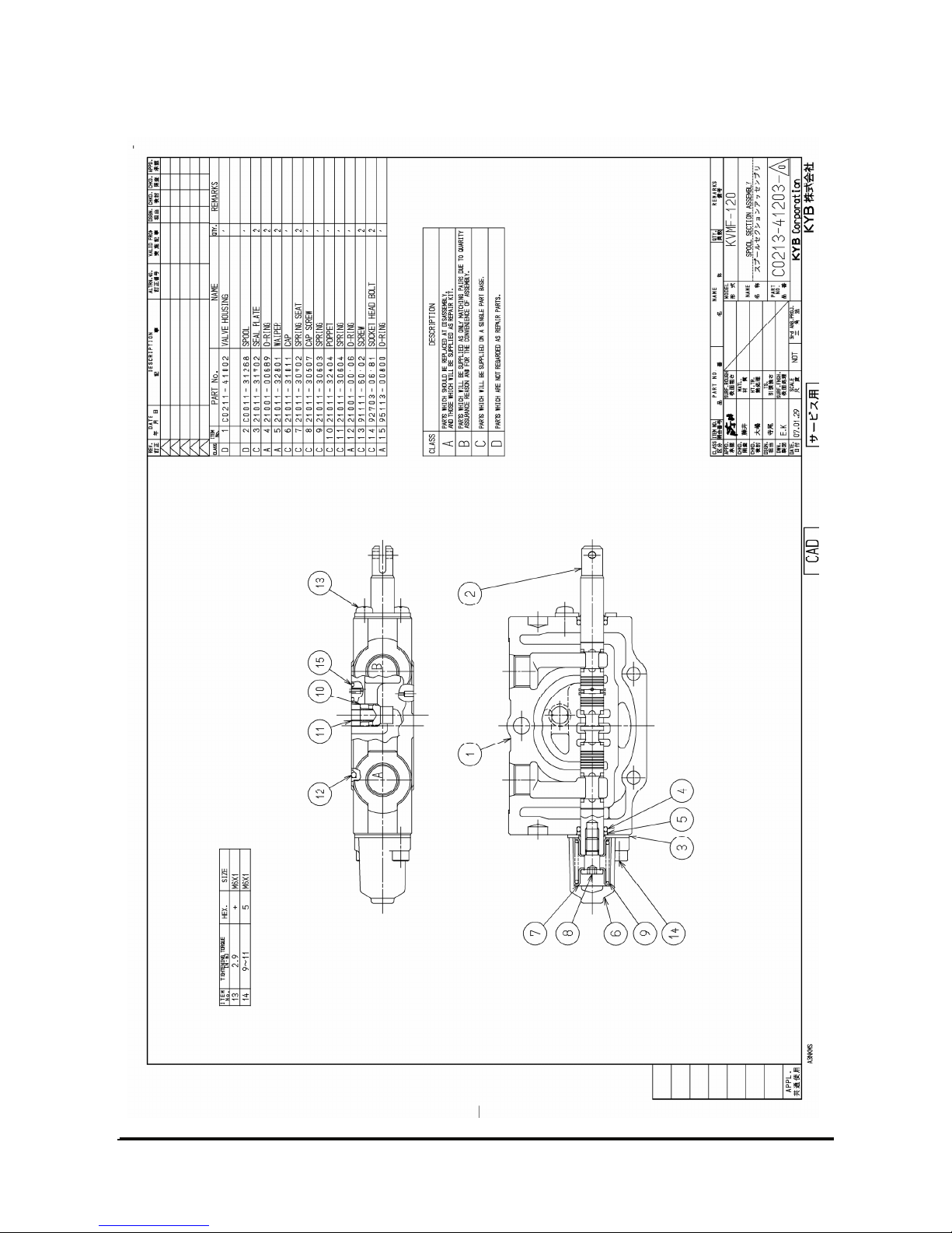
attached Part List (Part No.: C0213-41201).
Fig. 2-2 is the detail drawing.
1. Take out the O-rings(12) & (18) from the fitting
surface, remove spring(11) and poppet(10).
2. Unscrew the socket head bolt(14) and take out
the cap(6).
Take out the spool(2) in sub-assembled state from
the valve housing(1). At this time, remove the seal
plate(3), wiper(5) and O-ring(4), on the cap side,
as mounted on the spool(2).
3. Loosen the screw(13) on the opposite side,
remove seal plate(3), wiper(5), and O-ring(4).
Page 19

Vehicle Systems Disassembly & Assembly 17
4. Hold the spool(2) in a vise using rigid wood
pieces(Fig. 2-1) to prevent damage. Remove cap
screw(8) and remove spring seat(7), spring(9),
wiper(5) and O-ring(4). At this time, take care that
cap screw or other parts are not ejected out by the
force of the spring(9).
5. Remove spring(16) from inside the spool(2).
Remove the valve(15) from the spool(2) by
unscrewing the M4 screw at its end.
Disassembling the Spool Section
Assembly for Attachment
The combination shall be in accordance with the
attached Parts List(Part No. C0213-41202).
The disassembling of the Part No. C0213-41203 in
the attached Parts List is same as this section,
therefore, not described.
1. Remove O-rings(12), (18) from the fitting surface,
and remove spring(11) and poppet(10).
2. Unscrew socket head bolt(15) and remove cap(6).
Take out the spool(2) from the valve housing(1) in
sub-assembled state. At this time, remove seal
plate(3), wiper(5) and O-ring(4) on the cap side as
mounted on the spool.
3. Remove the screw(13) on the opposite side.
Remove seal plate(3), O-ring(4) and wiper(3).
4. Hold the spool(2) in a vise using rigid wood
pieces(Fig. 2-1) to prevent damage. Remove cap
screw(8) and remove spring seat(7), spring(9),
wiper(5) and O-ring(4). At this time, take care that
the cap screw or other parts are not ejected out by
the force of the spring(9)
The disassembled parts have to be arranged in
order to identify their assembly position on work
bench, shelf, etc.
Washing
Wash all the disassembled parts completely with
mineral oil.
Dry the washed parts with compressed air and
arrange them on clean paper or cloth for inspection.
Inspection
Inspect all the parts if they have any burr, scratch,
dent, or any other defect.
1. Confirm that the spool surfaces are free from
scratch or dent.
Small scratch can be removed with oil stone or
cloth with lapping material.
2. Reciprocating parts must move smoothly. All the
holes and paths must be free from foreign matter.
3. Worn, deformed, or broken spring must be
replaced.
4. Check that the sealing face of the valve housing
is smooth, free from dust, rust, or dent.
5. Remove any dent or scratch on the check valve
seat of valve housing by lapping. Take care not to
leave any lapping material in the valve.
6. If relief valve is not in normal order, inspect it in
compliance with the Relief Valve Maintenance
Manual.
7. Replace all the O-rings and back-up rings with
new ones.
8. Check that there is no residual coating debris
around the housing holes and plug seats.
In the event that coating debris is in the valve, it
will cause malfunction and oil leak.
Page 20
Vehicle Systems Disassembly & Assembly 18
Assembling
Take following cares when handling the O-rings.
1. Do not use any defective O-ring, whether the
defect was made in forming or handling,
2. Apply grease or hydraulic oil on O-ring and their
seats for full lubrication
3. Do not stretch O-ring severely. Otherwise, it may
be deformed.
4. Do not roll-in the O-ring when mounting it.
If O-ring is twisted, it may cause oil leak.
Take following cares when handling the spool.
1. Keep specified torque. Excessive torque will
cause malfunction of spool.
2. Take care that the spool, spring, and cap screws
are combined in the same assembly as they were
before the disassembling.
Take following cares when assembling section
assembly and valve assembly.
1. O-rings in the fitting face must not protrude out.
2. Before assembling, following points must be free
from any washing or hydraulic oil.
・Fitting faces of each section, outside of O-ring
grooves.
・Capping surfaces, outside the O-ring grooves.
If oil is left at above points, it may be mistaken
as the oil leak.
Assembling the Valve Housing
1. Assemble poppet(10), spring(11), O-rings(12),
(15) or (18) on each section surface.
2. Insert the tie rods(2), (4) (P/N C0240-41001,
attached Parts List) to fix them in the inlet section.
Assemble the valve housings of each section in
correct order. Finally, assemble the outlet housing.
On the tie rod, tighten nuts(1), (3) to specified
torque. Take care that the spring(11) on the fitting
surface does not hinder.
Spool Subassembly
With reference to the attached Part List of each
section assemblies, mount O-ring, wiper and seal
plate on the spool in specified order. Insert spring
between the spring seats and mount it on the spool
with cap screw.
Hold the spool in a vise with rigid wood pieces (Fig.
2-1) to prevent damage during assembling. Apply
grease around the spring.
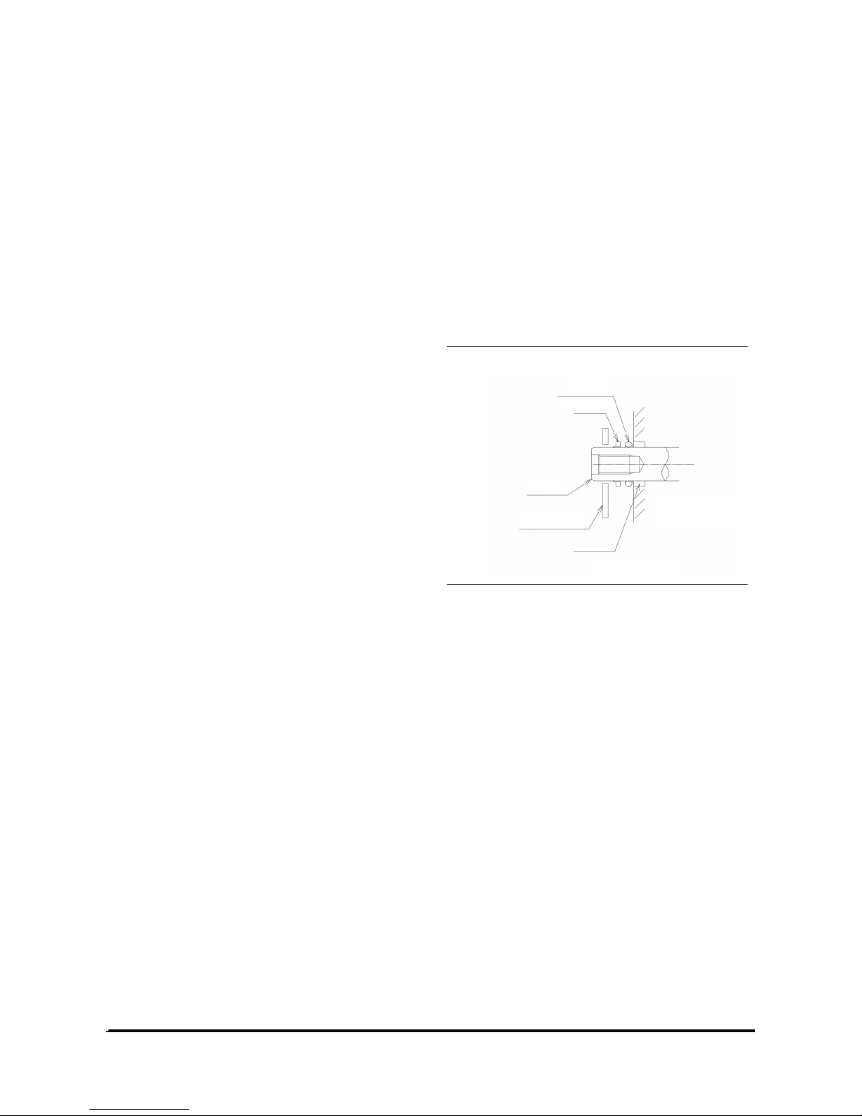
As shown in Fig. 5-1, the wiper must be mounted
with the protruded part facing outwards.
Be careful that the valve and spring are inserted in
the hollow space of the tilt spool only.
Protrusion
【Fig. 5-1】
O-rin
g
Spool
Seal Plate
Wiper
Seal Hole
Valve Hosing
Page 21
Vehicle Systems Disassembly & Assembly 19
Assembling Inlet Section Assembly
Combination number shall be in accordance with the
attached Part List (P/N: C0213-41001).
Tightening torque of each part shall be in
compliance with the Parts List.
1. Mount O-rings and wipers on each plug.
2. If the two plugs (42) and (59) were removed,
tighten them at the original position.
3. Insert the main poppet into the poppet (unload
valve) to make the poppet assembly(32), and
insert it into the inlet housing(1).
Then, insert the spring(33) into the main poppet,
and tighten the plug(34) making sure that its end
is inserted in the inside of the spring(33).
4. Take care when assembling the spool(26)
because the valve(28) is directional.
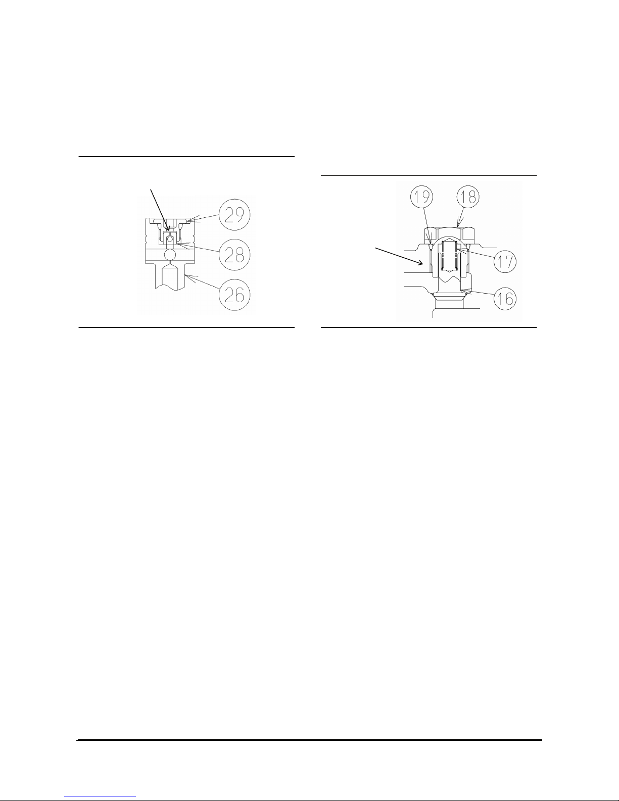
As shown in【Fig.5-2】, assemble with the orifice
F inside the plug(29), and insert the plug(29) into
the spool(26).
Then, while holding the spool(26) in a vise with
rigid wood pieces(Fig. 2-1) to prevent damage,
tighten the plug(26).
Finally, insert the spring(27) into the sub-
assembled spool(26), insert it into the inlet
housing(1) and tighten the plug(30).
5. Insert spring(51) into the spool(50), tighten
plug(52).
6. Assemble two relief valve assemblies (41) in the
original mounting ports. Take care not to confuse
the position.
7. Insert shuttle(36) into spring(37) and insert them
into inlet hosing(1).
At this time, the shuttle(36) may be ejected out by
spring(37) force. Place the solenoid(38) on the
end of the shuttle, slowly insert them into the
position where they will not come out by the
friction of the O-ring in the in-low part, and tighten
with socket head bolt.
8. Insert poppet into the main body of the shut-off
valve (20), mount them on the inlet housing(1).
And then tighten with set screw. Finally, join lock
nut onto the set screw.
9. Insert spring(17) into poppet(16).
Make sure to insert the larger diameter part of the
spring(17) into the poppet as shown in.
If assembled in opposite, the spring may be
broken.
Insert the poppet(16) inserted with spring(17)
Into plug(18), tighten to the inlet housing(1) so
that the Poppet(16).
10. Insert poppet(21) and spring(22) into inlet
housing(1). Tighten by turning the solenoid valve.
11. Assemble O-ring(3) and wiper(4) in the seal hole
on the spool head side of inlet housing(1). Fix
the seal plate(5) with screw(15).
12. Finally, insert the sub-assembled spool(2) from
the opposite side of the inlet housing(1), cover
with cap(13), and tighten with screw(15).
【Cautions For Inserting Spool】
Insert the spool slowly, vertically to the axis of the
hole. Reciprocate the spool with hands to check if
there is any resistive or uneven feeling which may
cause malfunction of the spool.
Orifice F
【Fig.5-2】
Coil Dia.
Page 22
Vehicle Systems Disassembly & Assembly 20
Assembling Spool Section Assembly
The combination numbers shall in accordance with
the pertinent Parts List.
Tightening torques of each part must be in
compliance with the Parts List.
1. Assemble O-ring(4) and wiper(5) in the seal hole
on the spool head side of the valve hosing (1). Fix
the seal plate(3) with screw(15).
2. Insert the sub-assembled spool(2) from the
opposite side of the valve hosing(1). Cover with
cap(6) and fix with screw(13).
Confirmation of Assembly Work
【Cautions for Assembling Work】
Check if there is any unassembled, missing part
after assembling. Missing part may cause oil leak.
Pressure Adjustment after Assembling
As shown in the main relief valve and second relief
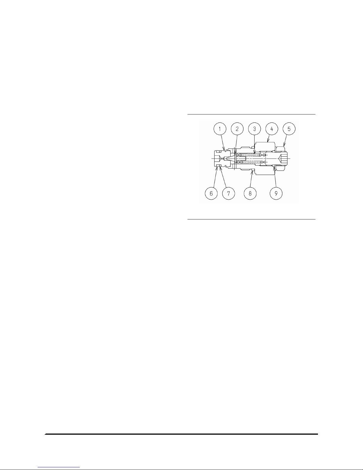
valve(Fig. 6-1), loosen the adjust kit(5) to release
pressure in all the circuits. Set the engine at the
rated rpm, block the circuit and slowly adjust the
pump port pressure to be the set pressure indicated
in the drawing, with the adjust kit(39). When
adjusted, tighten and lock with nut.
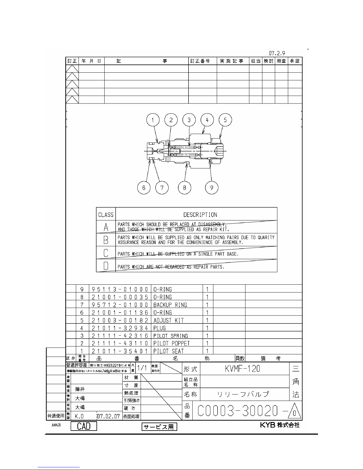
Relief Valve Maintenance
Main Relief Valve, Second Relief Valve
Disassembling
The combination numbers shall be in accordance
with the attached Part List(P/N: C0003-30020) and
Fig. 6-1.
Loosen the lock nut on the adjust kit (5) and remove
Spring (3) and pilot poppet (2) from the plug (4).
Since the pilot seat (1) has a hole at the end of the
Plug, do not disassemble it.
【Cautions for Disassembling Relief Valve】
Relief valve has to be replaced in assembly unit, in
principle. Do not disassemble it unless necessary.
The main poppet is built in the unload valve, as
described in the paragraph 1.2.
Page 23

Vehicle Systems Disassembly & Assembly 21
Washing, Inspection
Wash all parts with clean mineral oil. Dry with
compressed air for inspection.
1. The poppet seats and plugs must be free from
defect and smooth.
2. Main poppet and unload valve must be able to
reciprocate lightly and smoothly.
Outside of the main poppet and the inside of the
unload valve must be free from scratch or damage.
3. Spring (3) must be free from fracture, deformation
or wear.
4. The main poppet and pilot seat(1) holes must be
free from foreign matters.
5. O-rings and back-up rings must be replaced with
new ones.
If allowable scratch is identified, remove it by
lapping.
If any part is found to be defective, replace with a
new relief valve assembly.
Assembling
1. Mount O-ring and back-up ring on the pilot seat(1)
and adjust kit(5).
2. Insert poppet(2) and spring(3) into the plug(4),
and temporarily assemble the adjust kit(5)
mounted with O-ring.
3. Insert into the inlet housing and adjust the
pressure.
Assembling work of main poppet shall be in
compliance with the paragraph 5.3.
Note:O-rings and back-up rings must be replaced
with new rings, not reused.
Pressure Adjustment
1. Install an accurate pressure gauge at the circuit
inlet
2. Operate the pump at the rated rpm
3. Replace the spool of the control valve, read the
pressure gauge at the end of the cylinder stroke.
4. Turn the adjuster clockwise until desired pressure
is reached.
Each turn of adjuster will raise 17.7MPa of
pressure (reference value)
5. At the specified pressure, hold the adjuster and
tighten with lock nut. Specified torque: 27~31N
・m
6. Raise the pressure again to check if the specified
pressure is obtained
Note: When the main and second relief valves are
operated simultaneously, the setting pressure of the
main relief valve takes the precedence.
Installation
Take following cares at installation
・Pipe line must not exert unnecessary force to
valve.
・Mounting bolts must be tightened with same
torque.
・Welding work near valve may damage the seals
by excessive heat or scatter.
・Do not uncover valve ports until piping connection
to prevent dust from coming in.
Operation
・Valve arrangement must be in correct order.
Check that the hydraulic oil is clean, raise
pressure slowly(inching operation at low idle),
confirm that there is no external oil leak.
・Use hydraulic oil of which the annealing point is
82~113.
・Do not raise the pressure in the relief valve higher
than the specified setting pressure
・Make sure to provide sufficient warming up of the
machine before operation.
Especially, when starting up while the temperatures
of the hydraulic oil and valve is cold, take following
cares to prevent sticking of the spool by thermal
shock.
・Do not operate the main and second relief valves
successively during the warming up operation.
Circulate the hydraulic oil in the actuators to raise
temperature of all the parts evenly.
・Inching operation or composite operation may
cause local heating, therefore, must not be carried
out while the system is cold.
Page 24
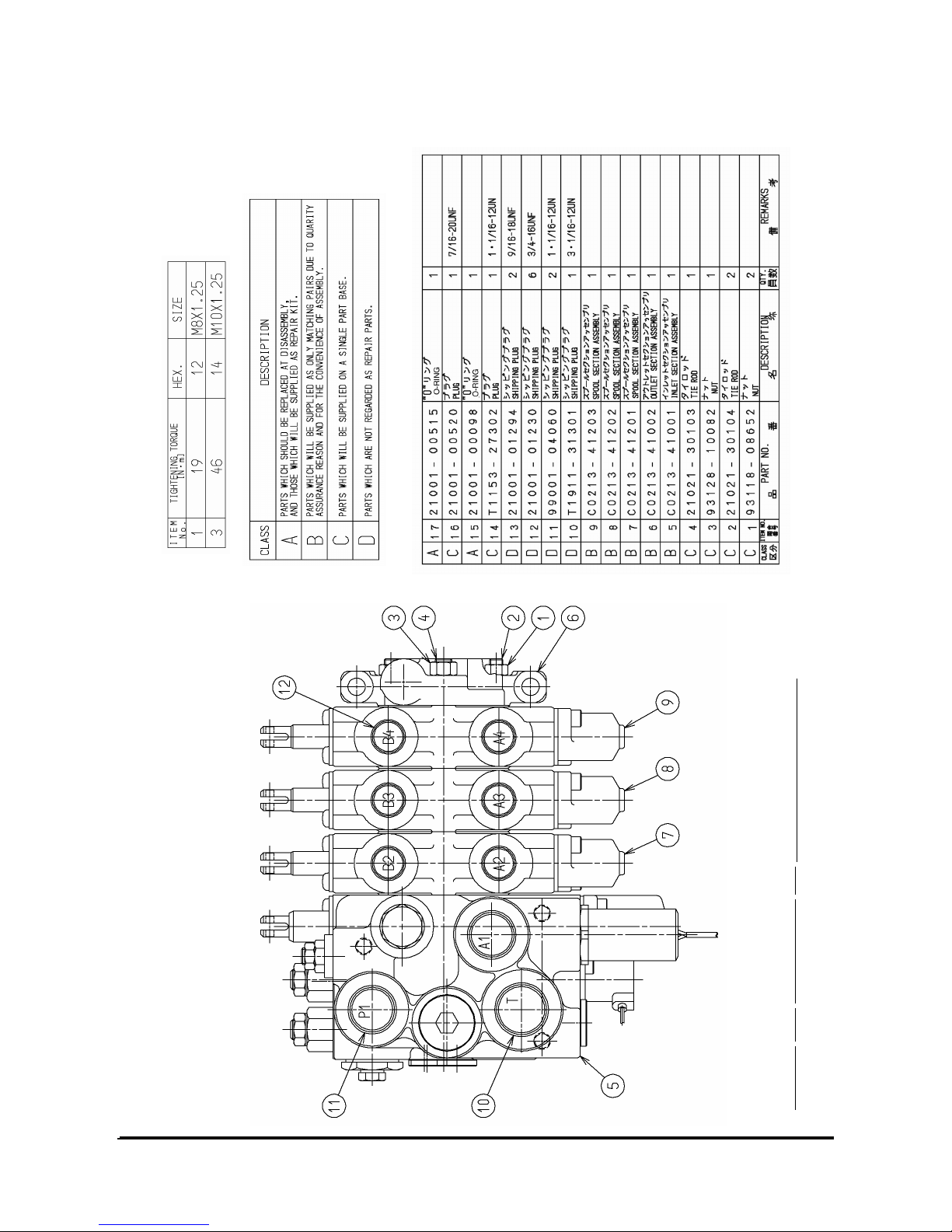
Vehicle Systems Disassembly & Assembly 22
Assembly Parts No.:Represent Item No.C0240-41001
Ref.No. GZ-MS-V0030
Page 25
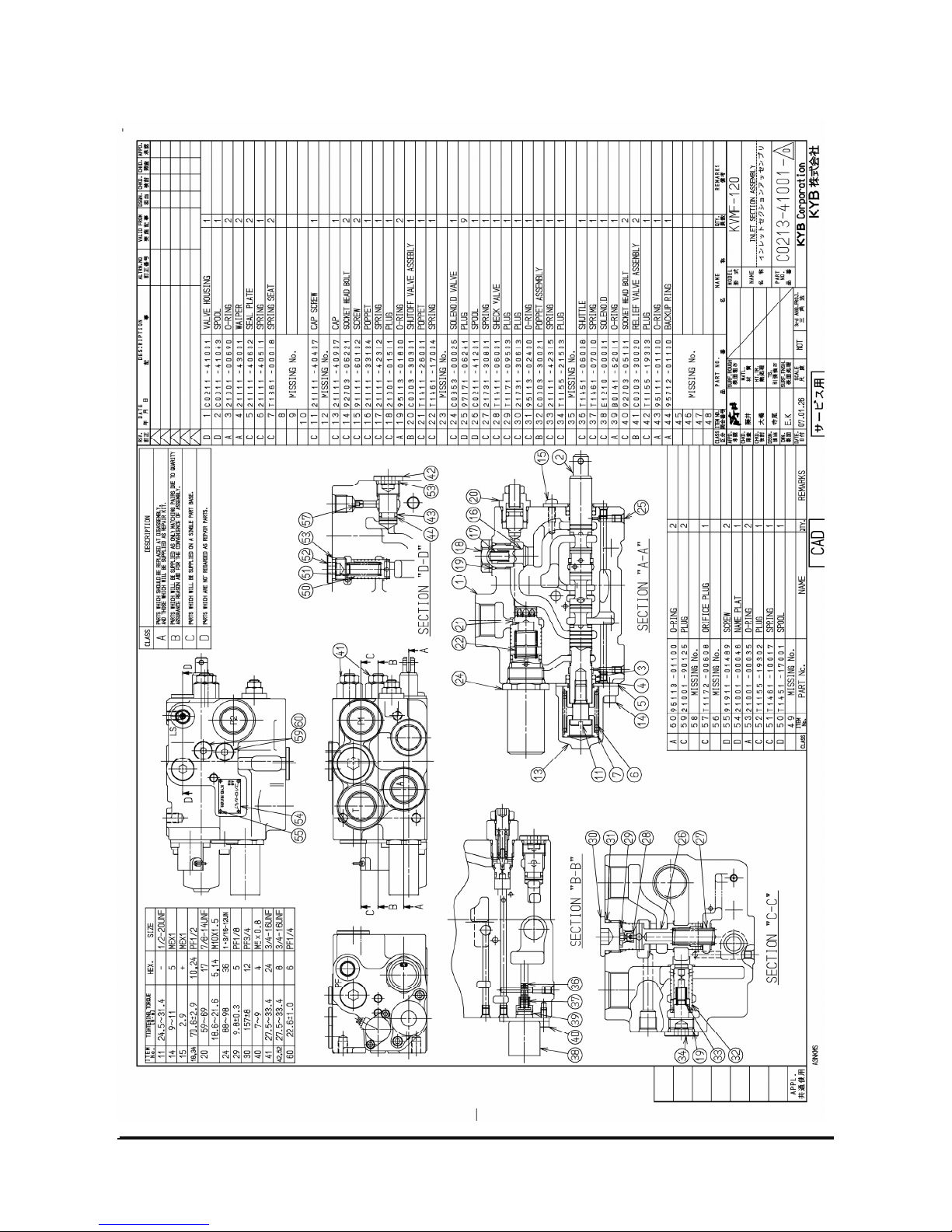
Vehicle Systems Disassembly & Assembly 23
Ref.No. GZ-MS-V0030
Page 26
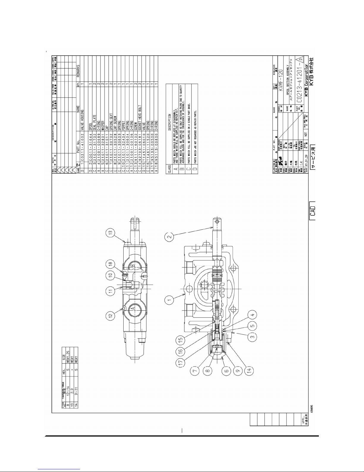
Vehicle Systems Disassembly & Assembly 24
Ref.No. GZ-MS-V0030
Page 27
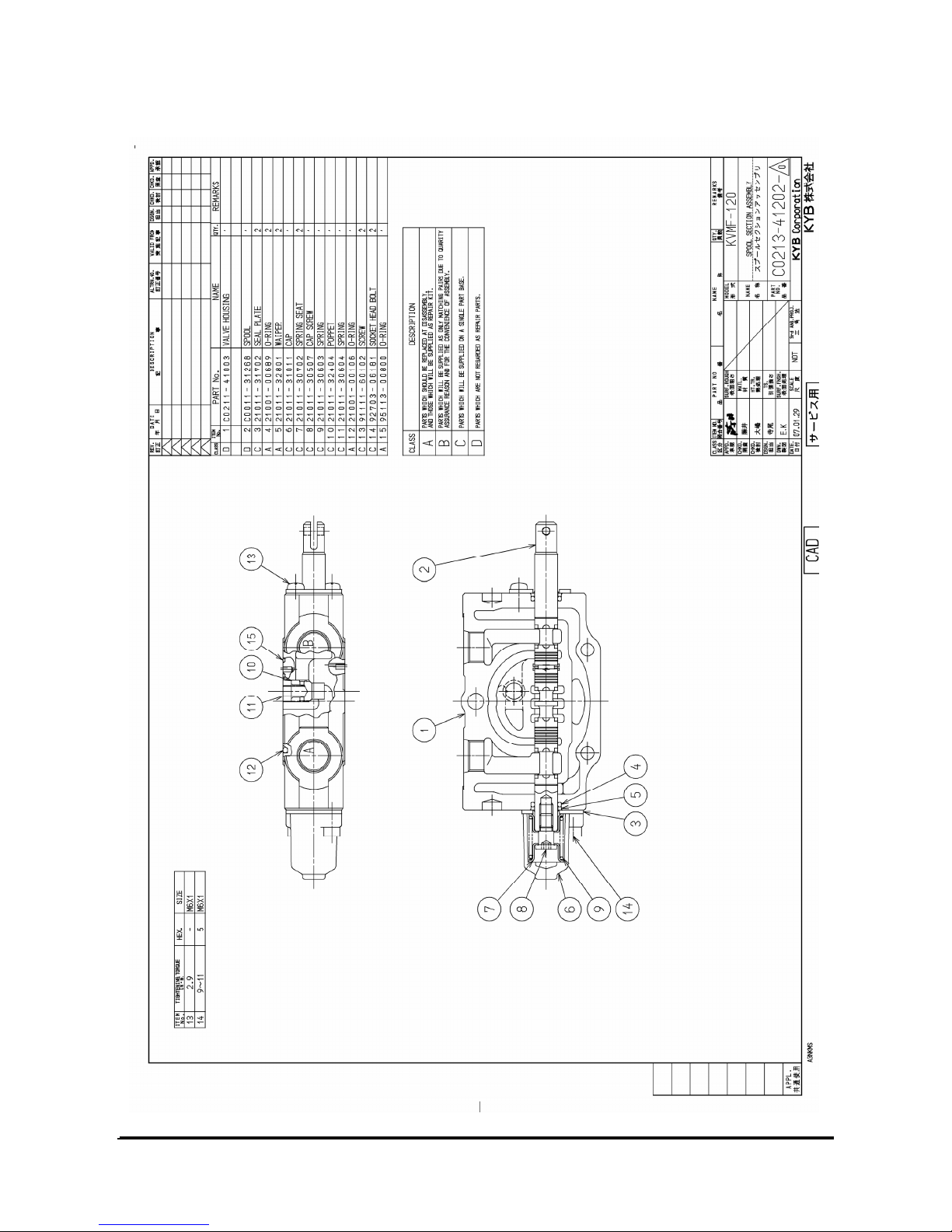
Vehicle Systems Disassembly & Assembly 25
Ref.No. GZ-MS-V0030
Page 28
Vehicle Systems Disassembly & Assembly 26
Ref.No. GZ-MS-V0030
Page 29
Vehicle Systems Disassembly & Assembly 27
Ref.No. GZ-MS-V0030
Page 30
Vehicle Systems Disassembly & Assembly 28
Ref.No. GZ-MS-V0030
Page 31
Vehicle Systems Disassembly & Assembly 29
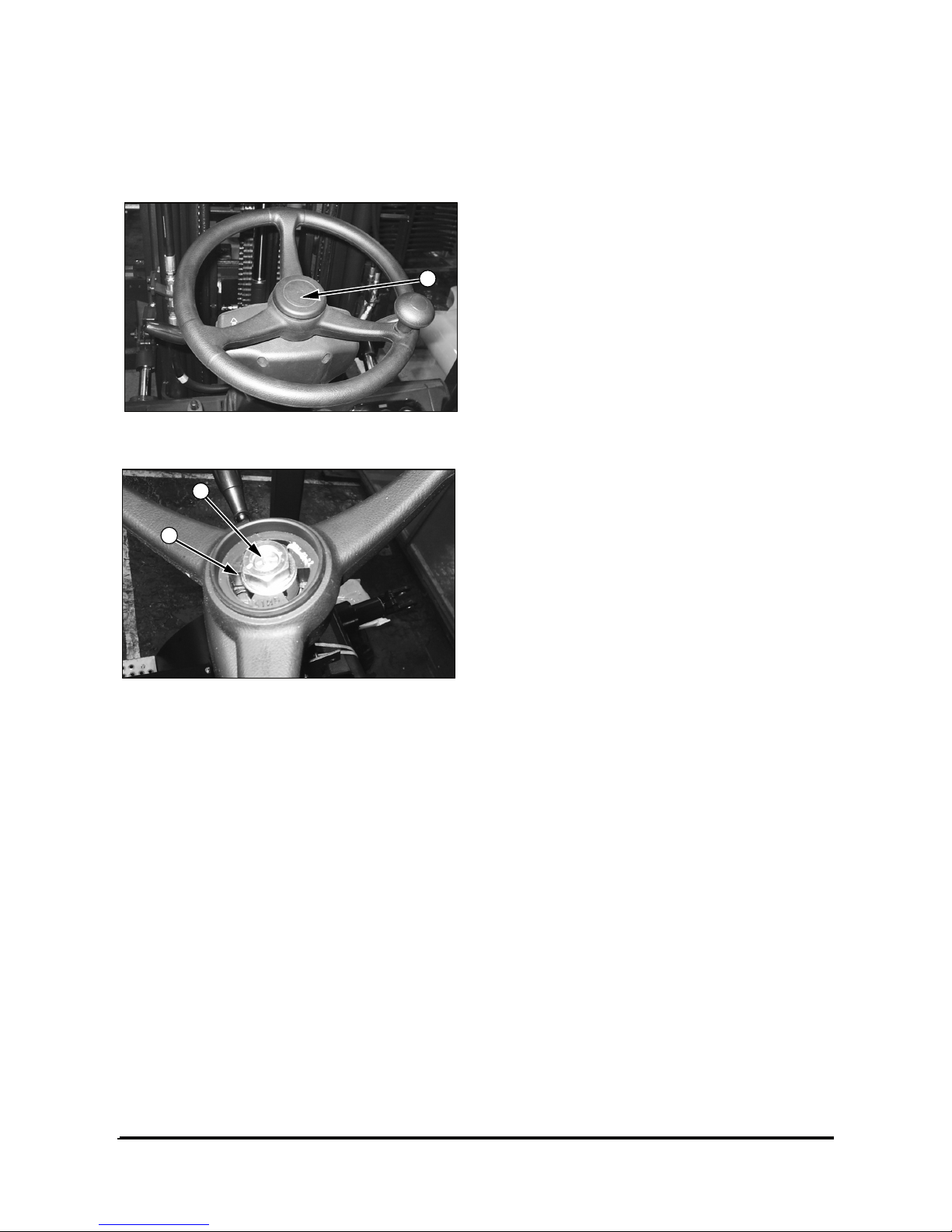
Steering Wheel
Remove & Install Steering Wheel
1. Remove cap (1) from the steering wheel.
2. Remove nut (2) and washer (3) from the steering
wheel shaft. Put location marks on the steering
wheel and the steering wheel shaft for installation
purposes.
3. Remove the steering wheel from the shaft.
NOTE: Use the following steps to install the
steering wheel.
4. Put the steering wheel on the steering wheel
shaft in its original position.
5. Install washer (3) and nut (2). Tighten nut (2) to a
torque of 80 ± 7 N•m (60 ± 5 lb•ft).
6. Install cap (1).
1
2
3
Page 32
Vehicle Systems Disassembly & Assembly 30
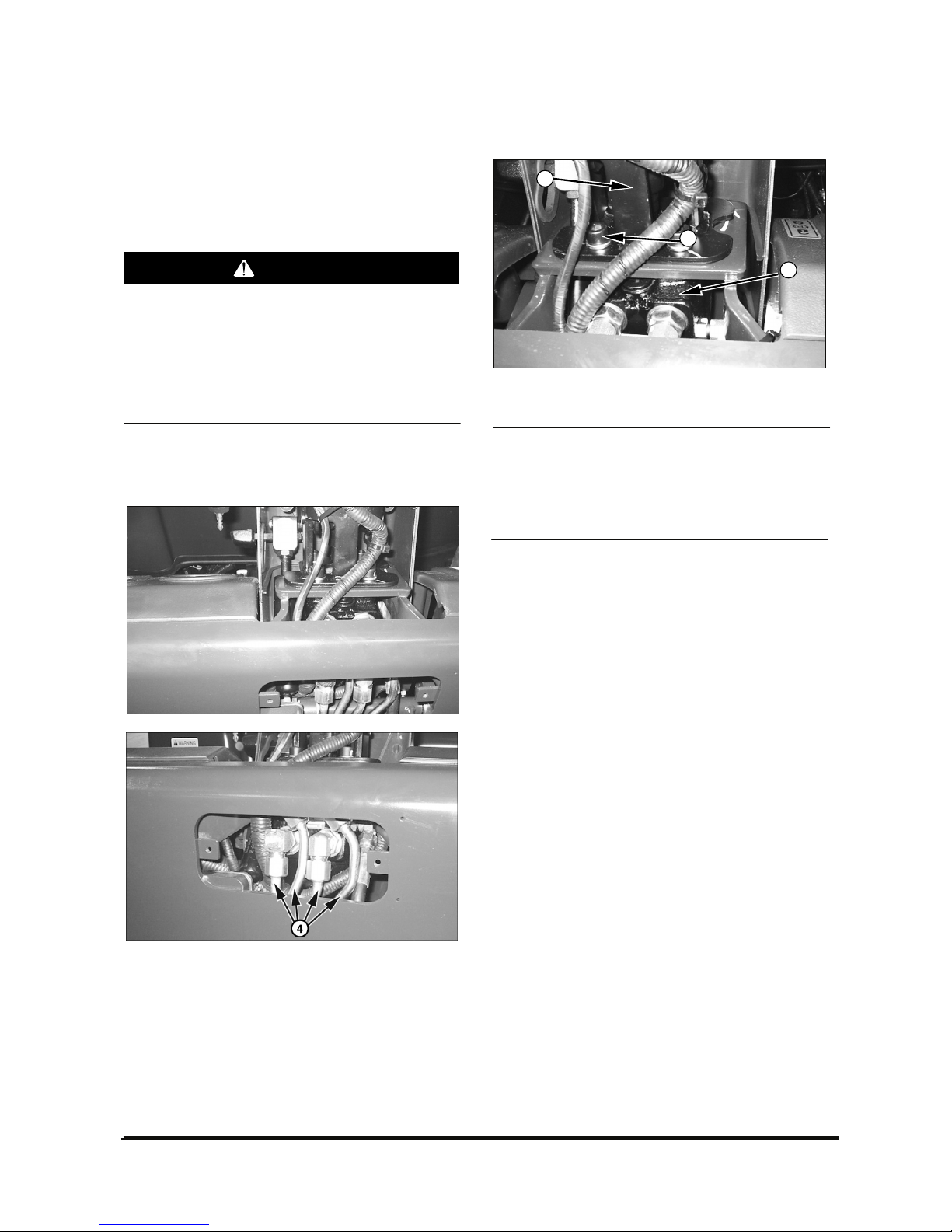
Steering Unit
Remove & Install Steering Unit
Start By:
a. Remove covers from steering wheel group
.
To prevent personal injury be sure pressure in
the hydraulic system has been released before
disconnecting any hydraulic lines. Slowly
loosen the cap of the hydraulic tank to release
any pressure in the tank. Be cautious of hot
hydraulic oil when any lines are disconnected
in the hydraulic system.
NOTE: Identify and mark all hydraulic hoses for
purposes of reassembly.
1. Disconnect (4) tubes and (1) hose assembled to
steering unit.
2. Remove four bolts (1).
NOTICE
Steering unit (2) and column (3) can separate after
bolts (1) have all been removed, causing unit (2) to
fall. To avoid damaging components, support the
steering pump while removing bolts (1).
3. Support steering unit (2) while removing the
remaining two bolts (1). Remove steering unit (2).
4. Install the steering unit in the reverse order of
removal.
End By :
a. Install the cover on steering wheel group.
WARNING
1
3
2
Page 33
Vehicle Systems Disassembly & Assembly 31
Disassemble Steering Unit
Cleanliness is extremely important when repairing a
steering unit. Work in a clean area. Before
disconnecting lines, clean port area of unit thoroughly.
Use a wire brush to remove foreign material and
debris from around exterior joints of the unit.
Although not all drawings show the unit in a vise, we
recommend that you keep the unit in the vise during
disassembly. Follow the clamping procedures
explained throughout the manual.
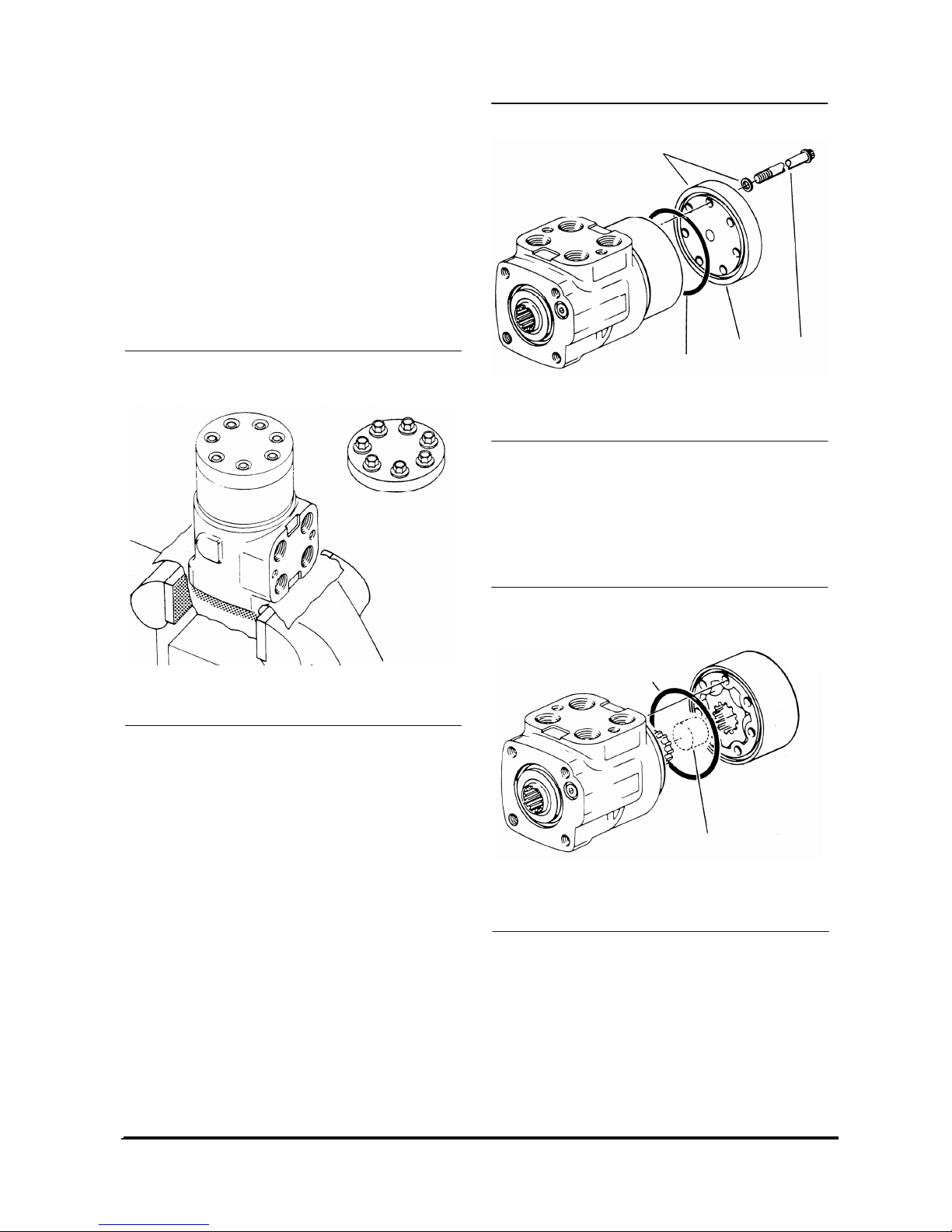
Gerotor (Meter) End
1. Clamp unit in vise, meter end up. Clamp lightly
on edges of mounting area. Use protective
material on vise jaws. Housing distortion could
result if jaws are overtightened.
2. Remove 5/16 inch cap screws and washers if
applicable (7 each).
3. Remove end cap.
4. Remove seal from end cap.
5. Remove meter. Be careful not to drop star.
6. Remove seal from meter.
7. Remove drive spacer(s).
IDCD278S
IDCD279S
Seal
End Cap Cap Screw
IDCD280S
Seal
Spacer(s)
Page 34
Vehicle Systems Disassembly & Assembly 32
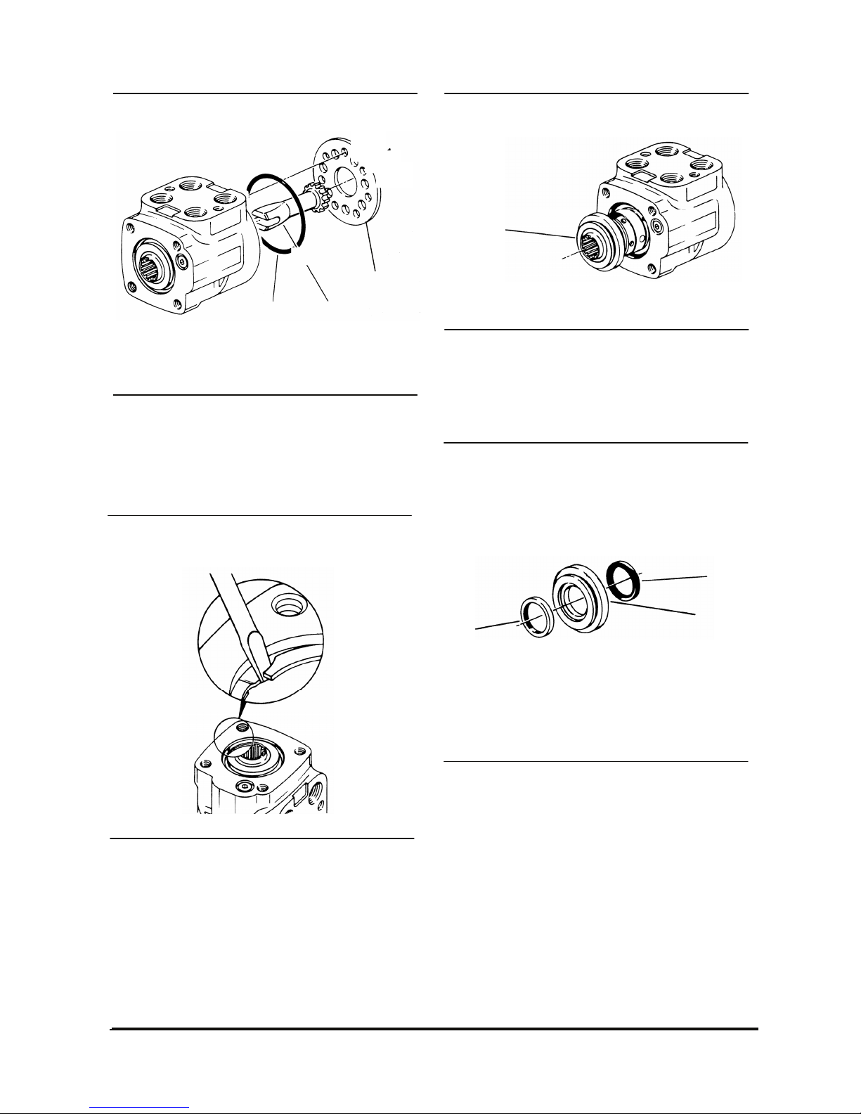
8. Remove drive.
9. Remove spacer plate.
10. Remove seal from housing.
11. Remove housing from vise. Place housing on a
clean soft cloth to protect surface finish. Use a
thin bladed screwdriver to pry retaining ring
from housing.
12. Rotate spool and sleeve until pin is horizontal.
Push spool and sleeve assembly forward with
your thumbs just far enough to free gland
bushing from housing. Remove bushing.
13. Remove quad ring seal from seal gland bushing.
14. Use a thin bladed screwdriver to pry dust seal
from seal gland bushing. Do not damage
bushing.
IDCD281S
Seal
Drive
Spacer Plate
IDCD282S
Control End
IDCD283S
Seal Gland
Bushing
IDCD284S
Seal
Gland
Bushing
Quad
Ring
Seal
Dust
Seal
Bearing
Page 35
Vehicle Systems Disassembly & Assembly 33
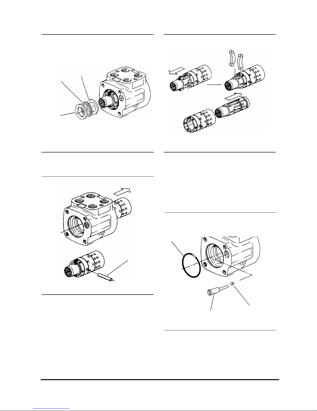
15. Remove 2 bearing races and the needle thrust
bearing from spool and sleeve assembly.
16. Remove spool and sleeve assembly from 14
hole end of housing.
ATTENTION: Do not bind spool and sleeve in housing.
Rotate spool and sleeve assembly slowly when
removing from housing.
17. Push pin from spool and sleeve assembly.
18. Push spool partially from control end of sleeve,
then remove 4 centering springs from spool
carefully by hand.
19. Push spool back through and out of sleeve.
Rotate spool slowly when removing from sleeve.
20. Remove seal from housing.
21. Remove check ball seat.
22. Tip housing to remove check ball.
IDCD286S
Pin
IDCD287S
IDCD288S
Check Ball
Check Ball Seat
Seal
Bearing
Race
IDCD285S
Bearing
Race
Needle
Thrust
Bearing
Page 36
Vehicle Systems Disassembly & Assembly 34
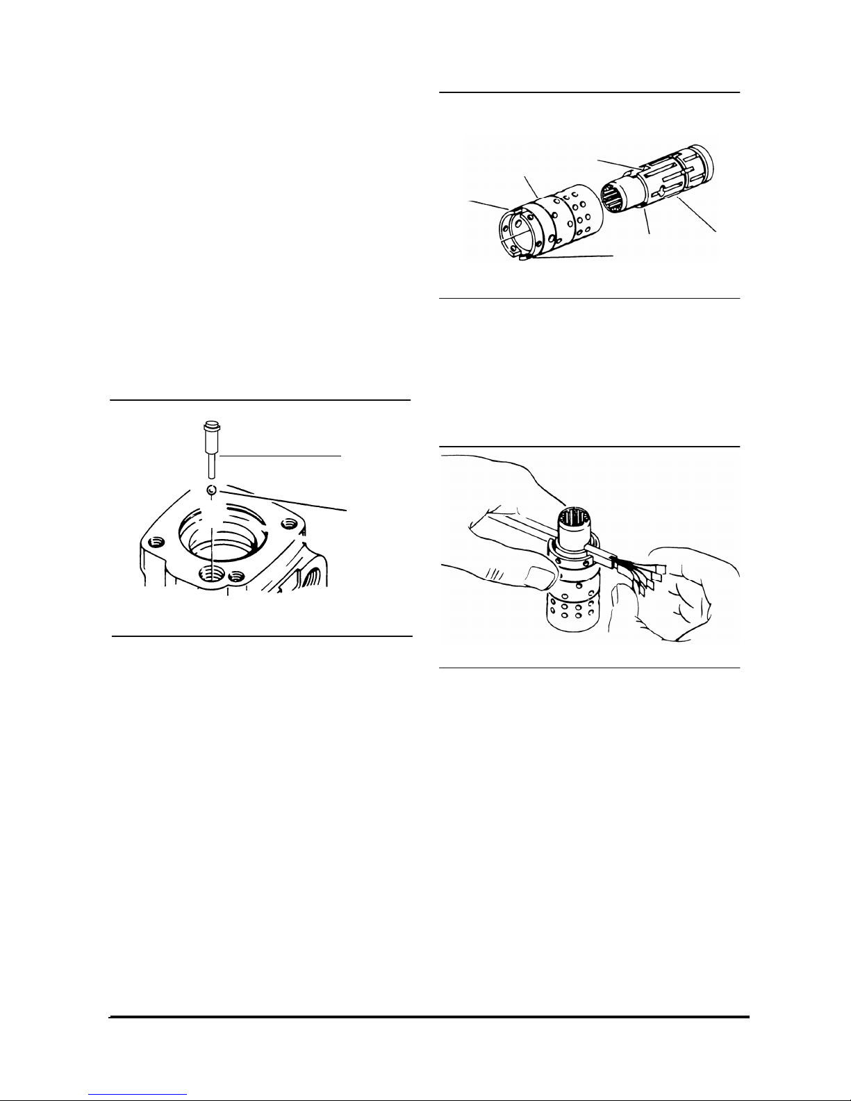
Assemble Steering Unit
Check all mating surfaces. Replace any parts that
have scratches or burrs that could cause leakage.
Clean all metal parts in clean solvent. Blow dry with air.
Do not wipe dry with cloth or paper towel because lint
or other matter can get into the hydraulic system and
cause damage. Do not use a coarse grit or try to file or
grind these parts.
NOTE: Lubricate all seals with clean petroleum jelly
such as Vaseline.
Do not use excessive lubricant on seals for meter
section.
Refer to parts listings covering your steering unit when
ordering replacement parts. A good service policy is to
replace all old seals with new seals.
1. Use a needle nose pliers to lower check ball
retainer into check valve hole of housing. Make
sure retainer is straight (not tilted on edge) in
housing.
2. Install check ball in housing
3. Lubricate 9.3 mm [.36 in.] ID seal and 7.7 mm
[.30 in.] ID seal. Install seals on check ball seat
as shown.
4. Lubricate check ball seat and seals thoroughly
before installing seat in housing. When installing
seat do not twist or damage seals. Install check
ball seat in housing, insert open end of seat first.
Push check ball seat to shoulder of hole.
5. Install set screw. Use a 1/4 inch hex key to
torque set screw to 11 N·m [100 lb·in]. To prevent
interference make sure top of set screw in slightly
below housing mounting surface.
6. Assemble spool and sleeve carefully so that the
spring slots line up at the same end. Rotate spool
while sliding parts together. Some spool and
sleeve sets have identification marks, align these
marks. Test for free rotation. Spool should rotate
smoothly in sleeve with finger tip force applied at
splined end.
7. Bring spring slots of both parts in line and stand
parts on end of bench. Insert spring installation
tool through spring slots of both parts. Position 2
pairs of centering springs on bench so that
extended edge is down and arched center
section is together. In this position, insert one end
of entire spring set into spring installation tool,
with spring notches facing sleeve.
8. Compress extended end of centering spring set
and push into spool sleeve assembly withdrawing
installation tool at the same time.
9. Center the spring set in the parts so that they
push down evenly and flush with the upper
surface of the spool and sleeve.
10. Install pin through spool and sleeve assembly
until pin is flush at both sides of sleeve.
IDCD289S
Check Ball
Check Ball
Seat
IDCD290S
Spring Slot
Control
Spool
Marks
Spring Slot
Identification
Control Sleeve
IDCD291S
Page 37
Vehicle Systems Disassembly & Assembly 35
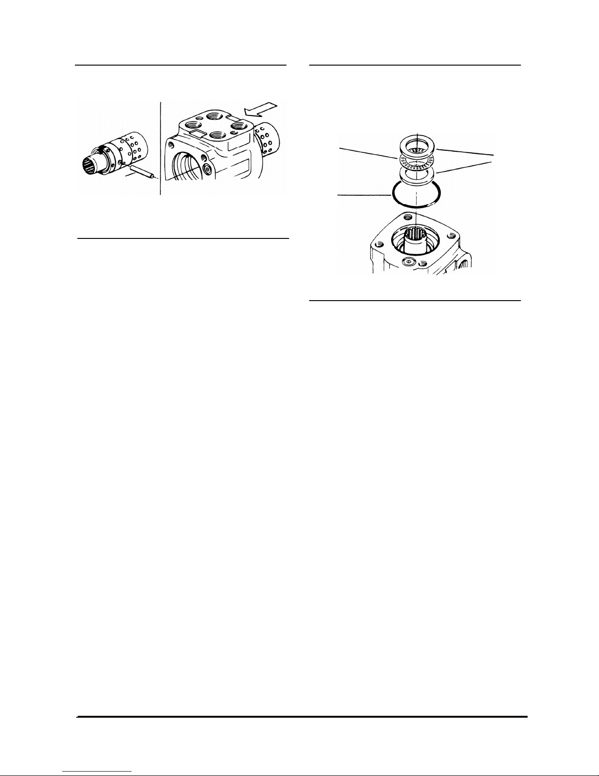
11. Position the spool and sleeve assembly so that
the splined end of the spool enters the 14 hole
end of housing first.
ATTENTION: Be extremely careful that the parts do
not tilt out of position while inserting. Push parts
gently into place with slight rotating action, keep pin
nearly horizontal. Bring the spool assembly entirely
within the housing bore until the parts are flush at
the meter end or 14 hole end of housing.
Do not pull the spool assembly beyond this point to
prevent the cross pin from dropping into the
discharge groove of the housing. With the spool
assembly in this flush position, check for free
rotation within the housing by turning with light
finger tip force at the splined end.
12. Place housing on clean lint free cloth. Install
47.5 mm [1.86 in.] ID seal in housing.
13. Install 2 bearing races and the needle thrust
bearing in the order shown.
14. Install 25 mm [1 in.] ID dust seal in seal gland
bushing, flat or smooth side must face down
towards bushing.
15. Install the quad ring seal in seal gland bushing.
Smooth seal in place with your finger. Do not
use any seal that falls freely into pocket of
bushing.
IDCD292S
IDCD293S
Bearing
Race(2
)
Needle
Thrust
Bearing
Seal
Pin
Page 38
Vehicle Systems Disassembly & Assembly 36
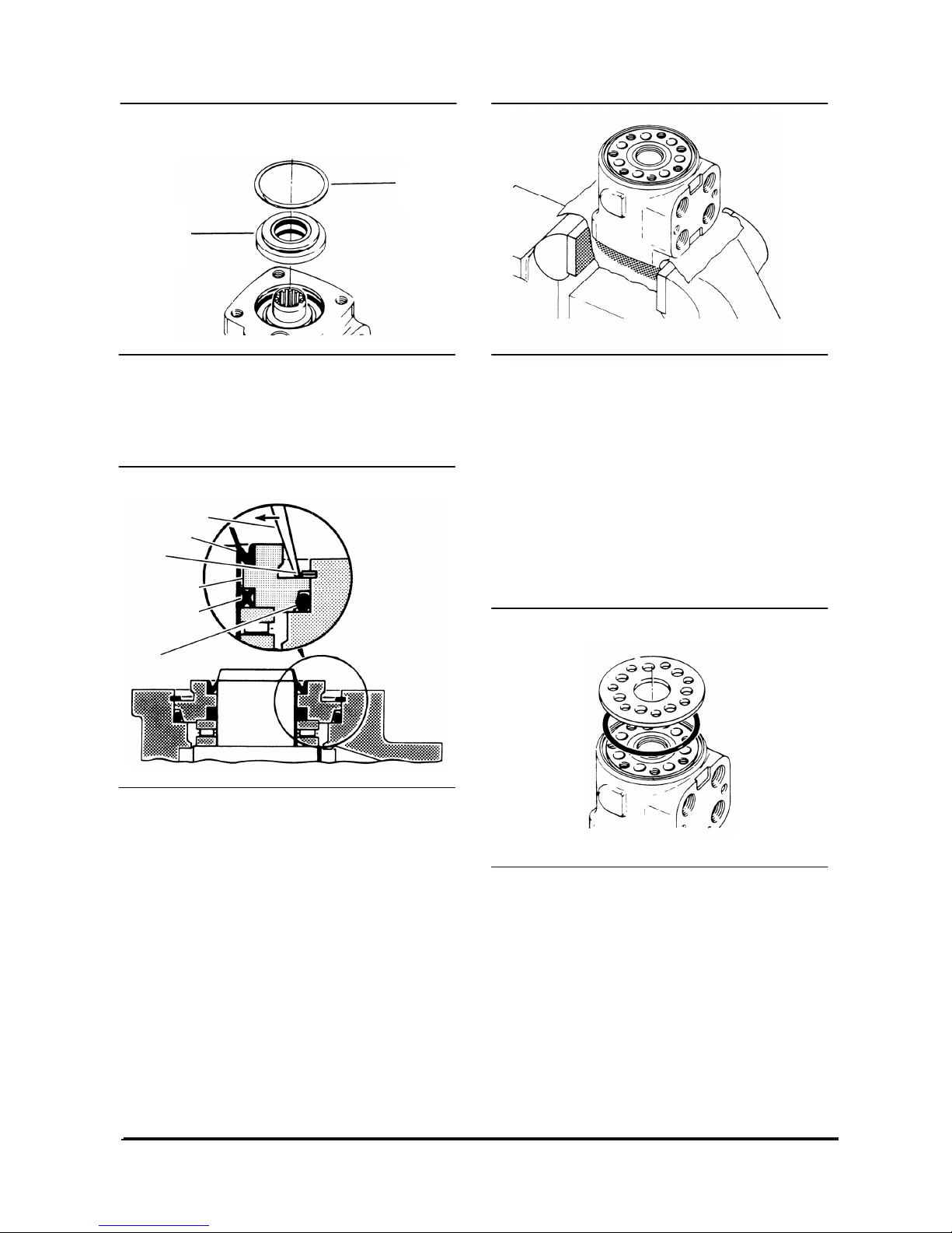
16. Install seal gland bushing over the spool end
with a twisting motion. Tap the bushing in place
with a rubber hammer. Make sure the bushing is
flush against the bearing race.
17. Install retaining ring in housing. After installing
ring, tap on ring end or pry with screwdriver
around entire circumference of ring to properly
seat ring in groove.
18. Clamp housing in vise. Clamp lightly on edges of
mounting area. Do not over tighten jaws.
NOTE: Check to insure that the spool and sleeve are
flush or slightly below the 14 hole surface of the
housing.
ATTENTION: Clean the upper surface of the housing
by wiping with the palm of clean hand. Clean each of
the flat surfaces of the meter section parts in a similar
way when ready for reassembly. Do not use cloth of
paper to clean surfaces.
19. Install 73.5 mm [2.89 in.] ID seal in housing.
20. Install spacer plate. Align bolt holes in spacer
plate with tapped holes in housing.
IDCD294S
Retainin
g Ring
Seal
Gland
Bushing
(with seals)
IDCD295S
Quad Ring
Screwdriver
Seal
Seal Gland
Bushing
Retaining
Ring
Dust Seal
IDCD296S
IDCD293S
Page 39
Vehicle Systems Disassembly & Assembly 37
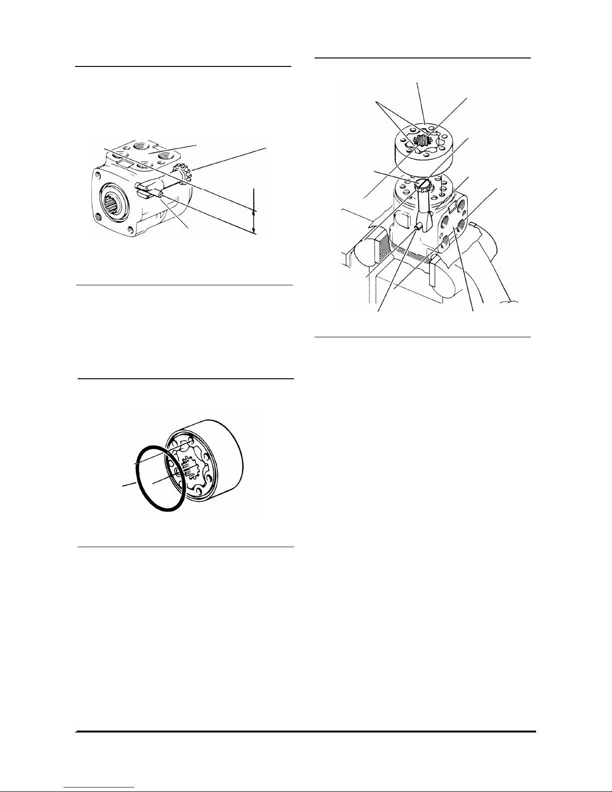
21. Rotate spool and sleeve assembly until pin is
parallel with port face. Install drive, make sure
you engage drive with pin. To assure proper
alignment, mark drive as shown. Note
relationship between slotted end of drive to
splined end of drive when marking.
22. Install 73.5 mm [2.89 in.] ID seal in spacer plate
or gerotor (meter).
23. With seal side of meter toward spacer plate,
align star valleys on drive. Note the parallel
relationship of reference lines A, B, C, and D.
Align bolt holes without disengaging meter from
drive.
IDCD298S
Drive
Port Face
Pin
Pin Parallel
with Port
Face
IDCD299S
Seal
IDCD300S
Drive
(Marked)
Star Valley
Pin
Port Face
Seal Groove this Side of Gerotor (Meter)
A
B
C
D
Page 40
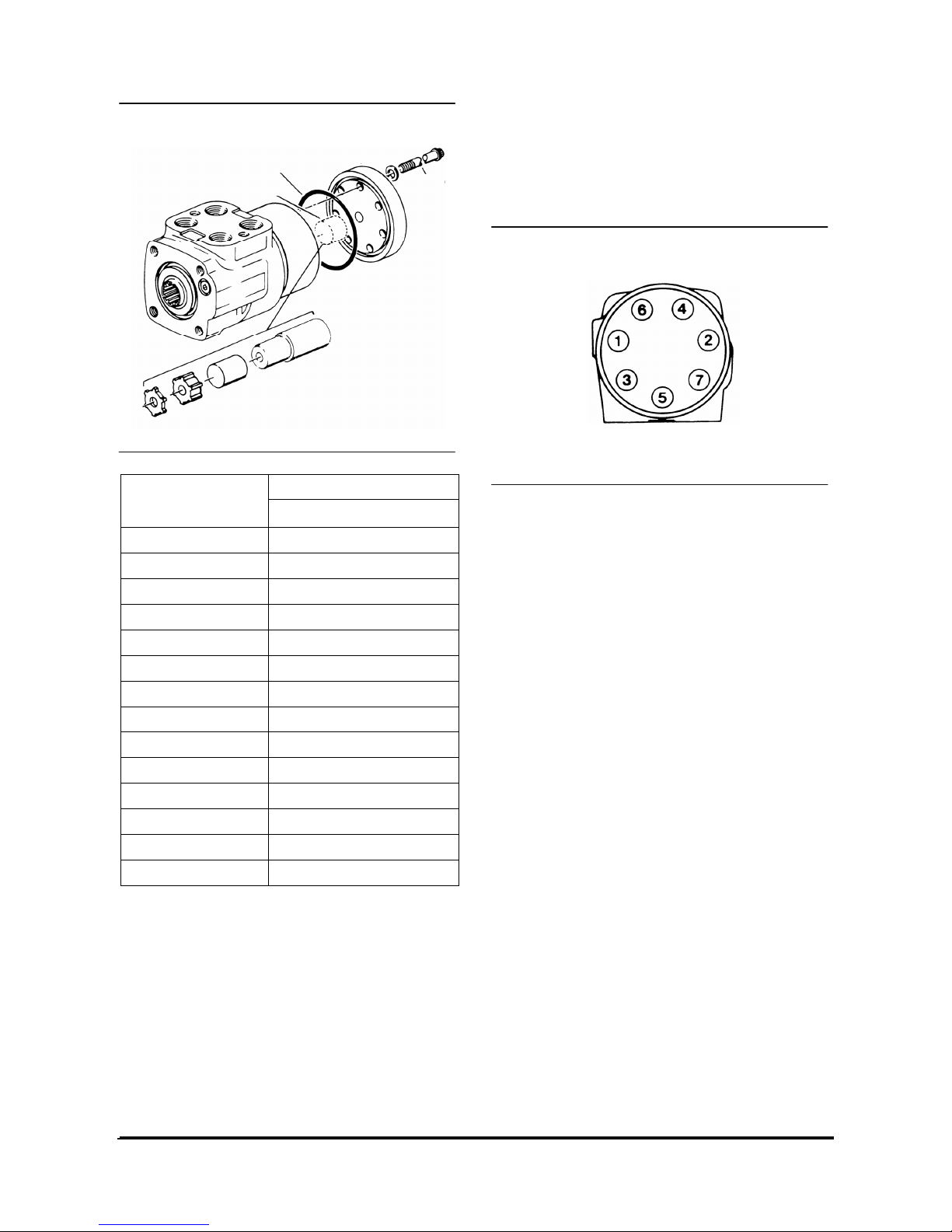
Vehicle Systems Disassembly & Assembly 38
Spacer
Actual
Displacement
㎤/r(in/r)
Length mm [in.]
45 [2.8] None
60 [3.6] None
75 [4.5] None
95 [5.9] 3.56 [.140]
120 [7.3] 6.10 [.240]
145 [8.9] 10.29 [.405]
160 [9.7] 12.19 [.480]
185 [11.3] 15.62 [.615]
230 [14.1] 21.97 [.865]
295 [17.9] 28.45 [1.120]
370 [22.6] 41.15 [1.620]
460 [28.2] 53.67 [2.113]
590 [35.9] 66.37 [2.613]
740 [45.1] 91.77 [3.613]
24. Install drive spacer (s) when used, in meter.
25. Install 73.5 mm [2.89 in.] ID seal in gerotor
(meter) or end cap, see notes.
26. Install end cap on gerotor, align holes.
27. Install 7 dry cap screws in end cap. Pretighten
screws to 11-17 N·m [100-150 lb·in] then torque
screws to specifications.
IDCD301P
Drive Spacer(s)
Seal
IDCD302P
3
Page 41
Vehicle Systems Disassembly & Assembly 39
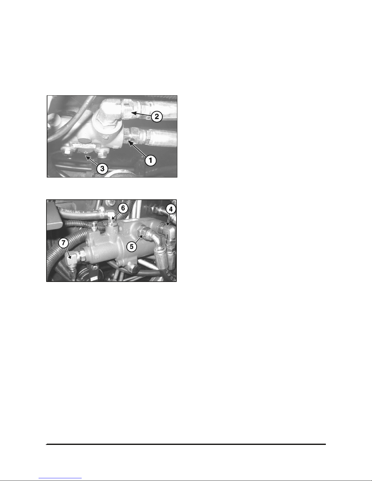
Brake Hydraulic Booster
Remove and Install Brake Hydraulic
Booster
Flow Control Valve
Brake Booster
1. Remove the floor plate.
2. Disconnect pressure line (1).
3. Disconnect the line from Flow contol valve to
Booster (2).
4. Disconnect return line (3).
5. Disconnect pressure line (4).
6. Disconnect return line (5) and brake reservoir line
(6).
7. Disconnect brake line (7).
NOTE: The following steps are for installation of the
brake master cylinder.
1. Installation is the reverse order of removal. Be
sure to check the leakage between the
connections.
2. Remove the air (bleed the brake lines). See the
topic of Brake System Air Removal.
3. Install the floor plate over the brake hydraulic
booster.
Page 42
Vehicle Systems Disassembly & Assembly 40
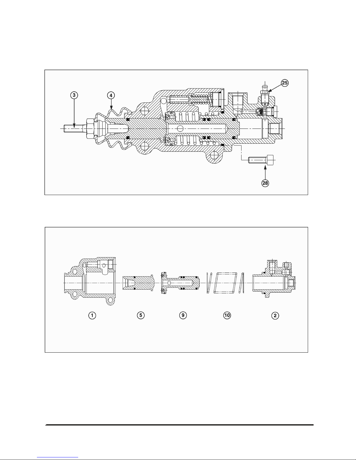
Disassemble & assemble brake valve
1. Take off bellows (4) and lift push rod (3), remove vent air (25) and bolts (28).
2. Separate the front housing (1) and rear housing (2), remove servo spring (10), servo piston (9) and master
piston (5).
Page 43
Vehicle Systems Disassembly & Assembly 41
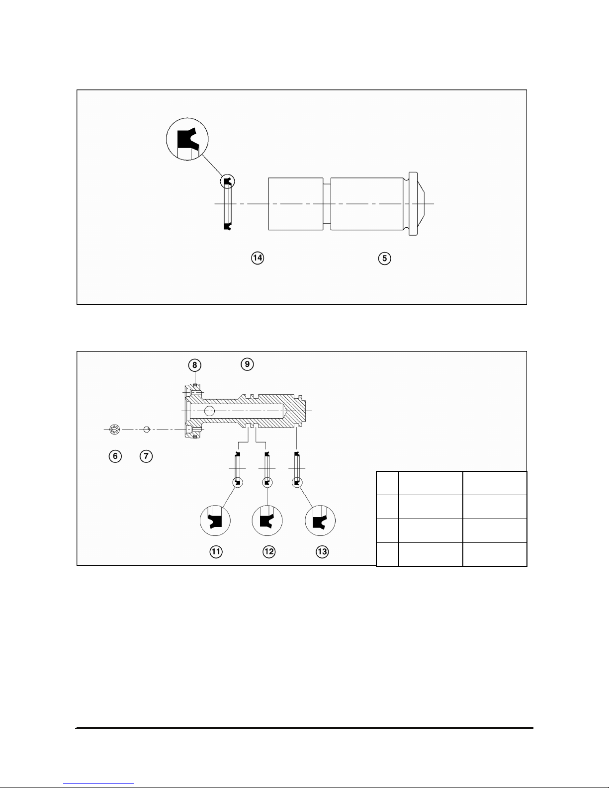
3. Take off seal u-cup (14) from master piston (5). Notice the direction of the seal.
4. Remove lock washer (6) and ball (7) from servo piston (9). Pull off piston ring (8), seal u-cup (13), seal u-
cup (12) and seal u-cup (11) in sequence. Notice the direction of each seal.
Page 44
Vehicle Systems Disassembly & Assembly 42
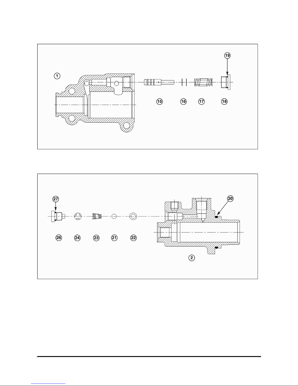
5. Remove relief plug (18), o-ring (19), spring (17), shims (16) and piston (15) from front housing (1).
6. Remove check valve parts from rear housing (2): plug (26), o-ring (27), cage (24), spring (23), ball (21) and
o-ring (22). Remove o-ring (20).
7. Assemble brake valve in the reverse order of disassembly.
Page 45
Vehicle Systems Disassembly & Assembly 43
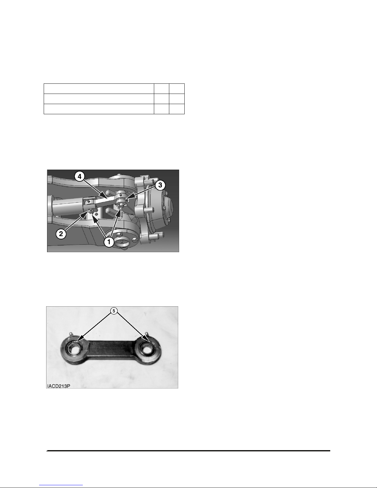
Tie Rods
Remove And Install Tie Rods
Floor Jack 1
Drive Set 2
Start By :
a. Remove steer wheels.
NOTE: The procedure to remove and install the tie
rod is the same for each steer wheel.
1. Support the steer axle with a floor jack (A).
Position the wheel to gain access to the tie rods.
2. Remove two split pins (2). Remove pins (1).
3. Remove tie rod (4) and dust seals (3).
4. Use tooling (B) to remove bearings (5) from the
tie rod.
5. Use tooling (B) to install new bearings (5) in the
tie rod.
6. Install the tie rod in the reverse order of removal.
Page 46
Vehicle Systems Disassembly & Assembly 44
Steering Knuckles, Kingpins,
And Bearings
Remove And Install Steering Knuckles,
King Pins And Bearings
Drive Set 1
Start By:
a. remove steer wheels
NOTE: The procedure to remove and install the
steering knuckles, kingpins, and bearings is the
same for both sides of the lift truck.
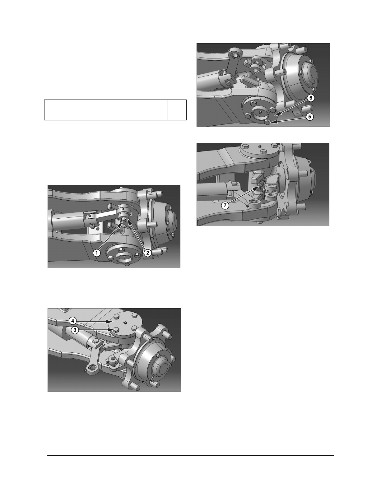
1. Remove two split pins (2). Remove pin (1).
2. Position the tie rod away from the steering
knuckle.
3. Remove four bolts (3) and cover (4).
4. Remove four bolts (5) and cover (6).
5. Remove the nut and bolt (7). For the purpose of
reassembly, the torque for bolt (7) is 11
± 1 N•m (8
± 1 lb•ft).
Page 47
Vehicle Systems Disassembly & Assembly 45
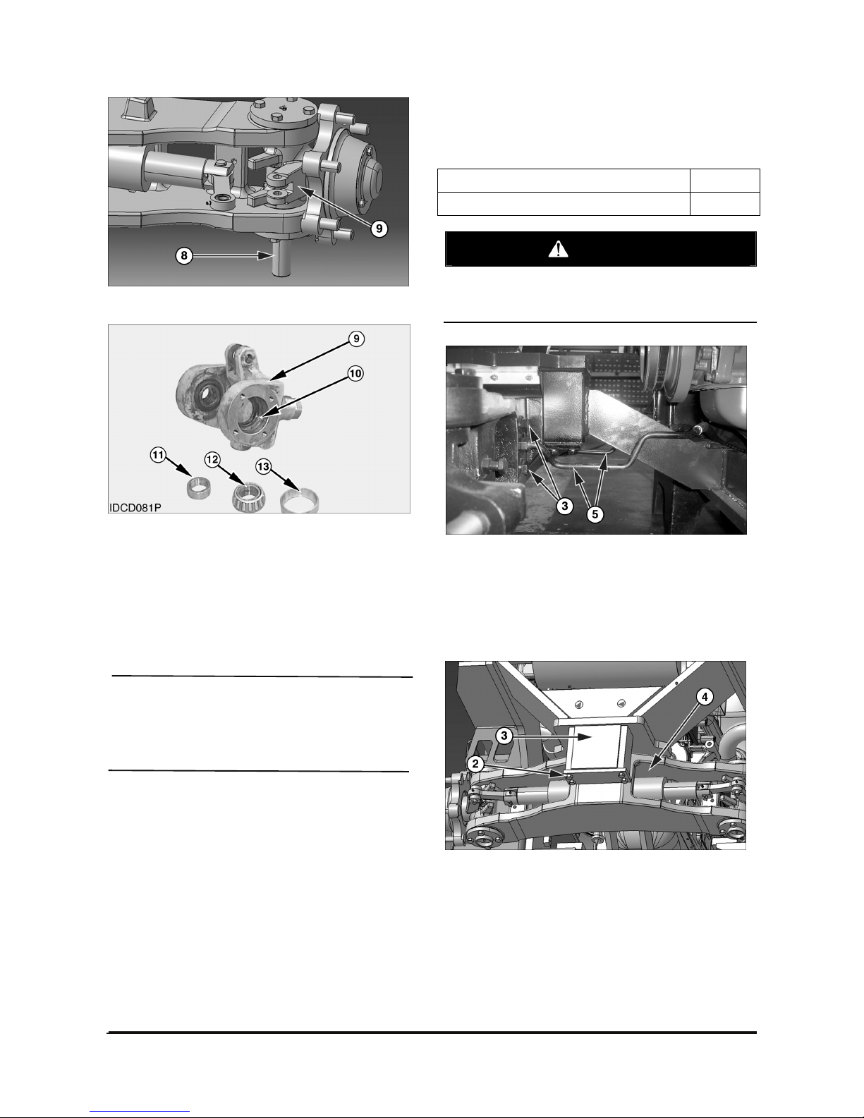
6. Remove kingpin (8) and knuckle (9).
7. Remove spacer (11), bearing cup (13) and
bearing cone (12).
8. Check the condition of lip type seal (10). Replace
seal (10) with new if worn or damaged.
9. Repeat steps 7 and 8 for the remaining seal,
bearing and spacer in the other side of knuckle (9).
NOTICE
10. Lubricate the pins, king pins and bearings.
11. Install the steering knuckle, kingpins and
bearings in the reverse order of removal.
End By:
a. Install steer wheels.
Steer Axle
Remove & Install Steer Axle
Tools Needed A
Jack Stand 4
WARNING
Be sure the pressure in the hydraulic system is
released before any lines or hoses have been
disconnected.
1. Put the lift truck in position on tooling (A).
2. For the purpose of reassembly, put identification
marks on hoses (1). Disconnect hoses (1). Plug
and cap all openings to prevent contamination and
debris from entering the system.
3. Support the steer axle with a floor jack.
4. Loosen mounting bolts (2) until approximately two
bolt threads are left in the mounting bosses.
5. Lower the steer axle onto the bolt heads with the
floor jack.
Page 48
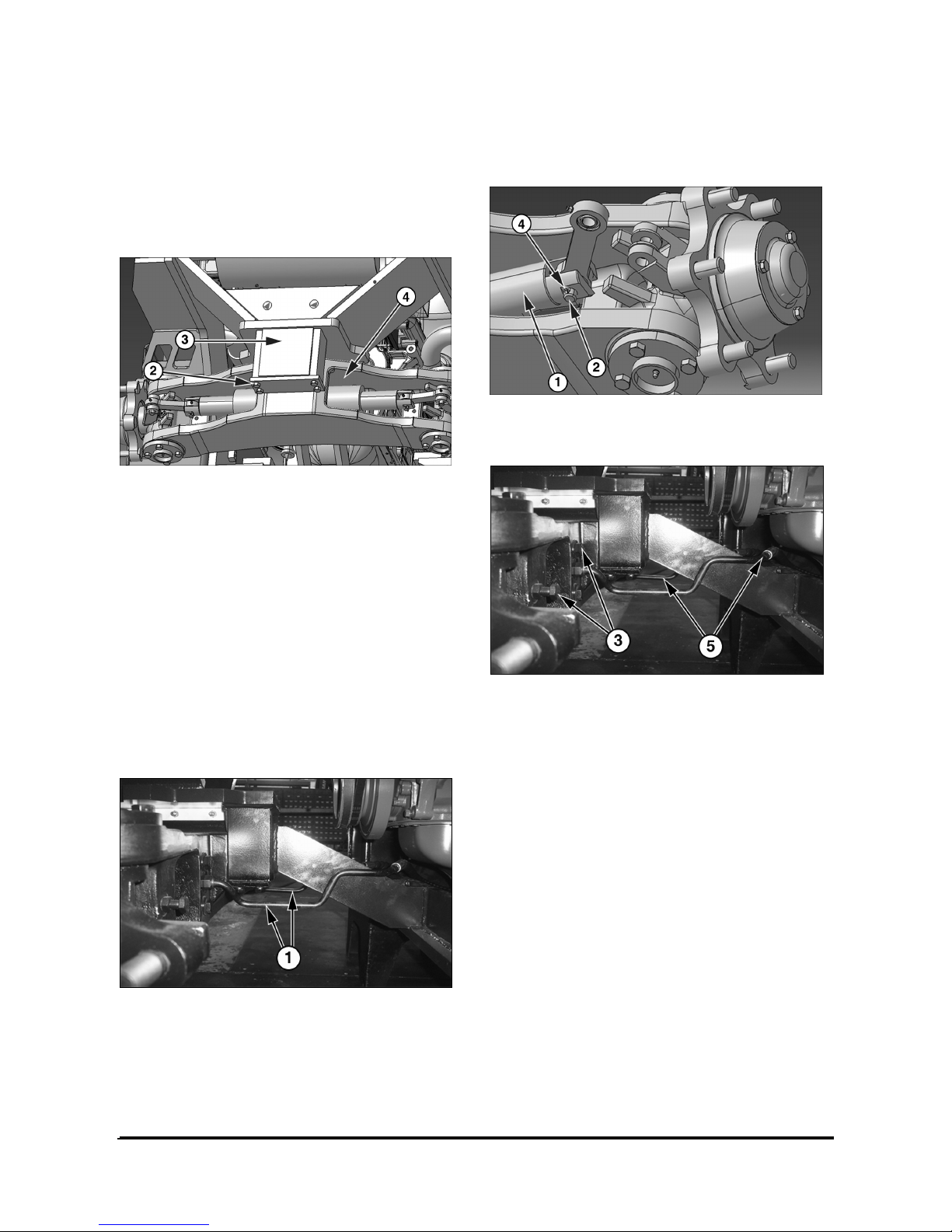
Vehicle Systems Disassembly & Assembly 46
6. Remove bolts (2) and mounting caps (3) from the
steer axle.
7. Remove steer axle (4). The steer axle weighs180
kg (400 lb).
NOTE : Use the following steps to install the steer
axle.
8. Use a floor jack to position steer axle (4).
NOTE: Use bolts (2) and cap (3) to align steer axle
(4) with the mounting bosses while raising steer axle
(4) into position with the floor jack.
9. Seat steer axle (4) as follows:
a. Install bolts (2) through cap (3) and into the
mounting bosses approximately two bolt
threads.
b. Use the floor jack to raise steer axle (4) into the
mounting boss.
c. Tighten bolts (2).
11. Connect hoses (1).
Steering Cylinder
Remove & Install Steering Cylinder
1. Remove the split (4) and pin (2) from the tie rod at
each end of steering cylinder (1).
2. Disconnect two hoses (5).
3. Remove four bolts (3). For installation purposes,
the torque for bolts (3) is 240
± 30 N•m (178 ± 22
lb•ft).
4. Remove steering cylinder (1).
5. Install steering cylinder (1) in the reverse order of
removal.
Page 49
Vehicle Systems Disassembly & Assembly 47
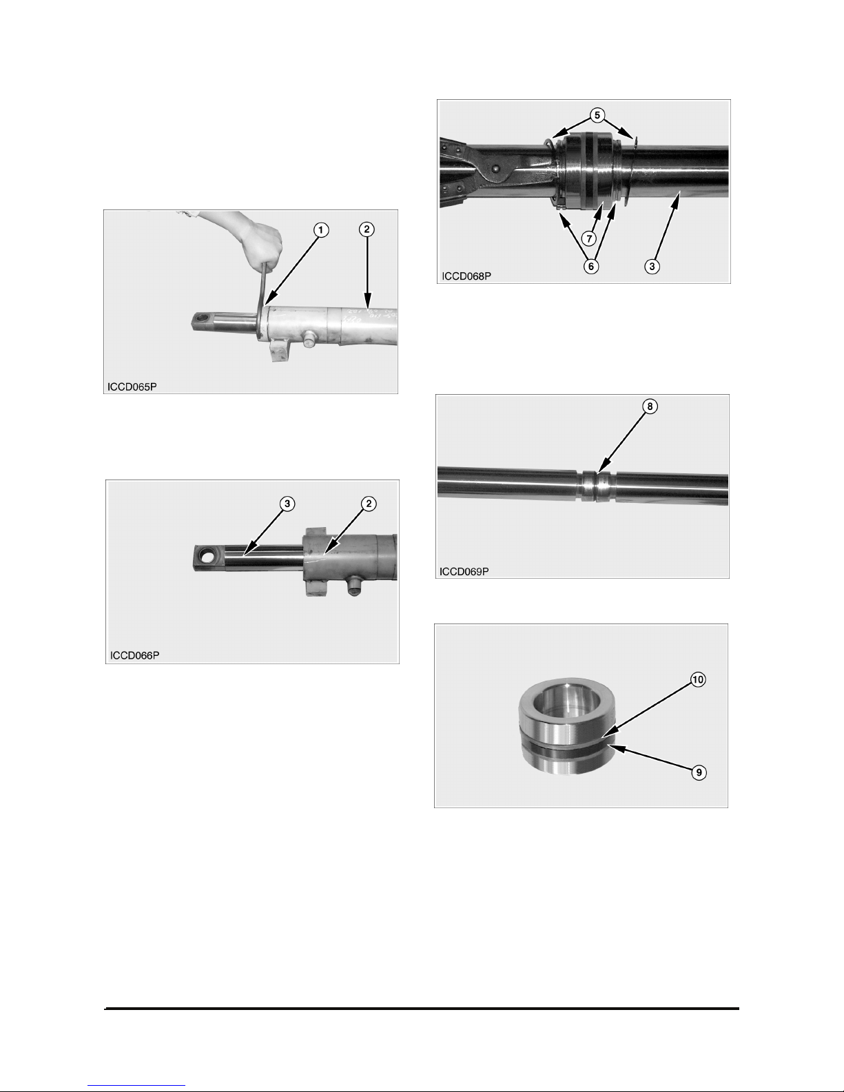
Disassemble And Assemble Steering
Cylinder
Start By :
a. Remove steering cylinder.
1. Put the steering cylinder in position in a vise.
2. Loosen head (1) from tube (2) with a spanner
wrench.
3. Remove rod assembly (3) from the tube (2).
4. Remove retaining ring (5) with a plier and ring (6)
from each side of piston (7) that holds piston in
position on rod (3).
5. Remove piston (7) from the rod (3).
6. Remove O-ring seal (8) from the rod.
7. Remove seal ring (9) and backup seal (10) from
the piston.
8. Loosen the head in the opposite end of the tube.
Page 50
Vehicle Systems Disassembly & Assembly 48
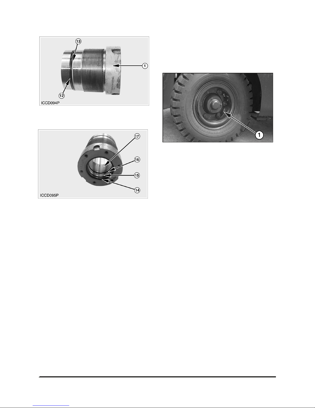
9. Remove O-ring seal (12) and backup ring (13)
from each head (1).
10. Remove wiper seal (14), backup ring (15), Upacking (16) and DU-bush (17) from the bore of
each head.
NOTE : Assemble the steering cylinder in the
reverse order of disassembly.
Tires And Rims (Steer)
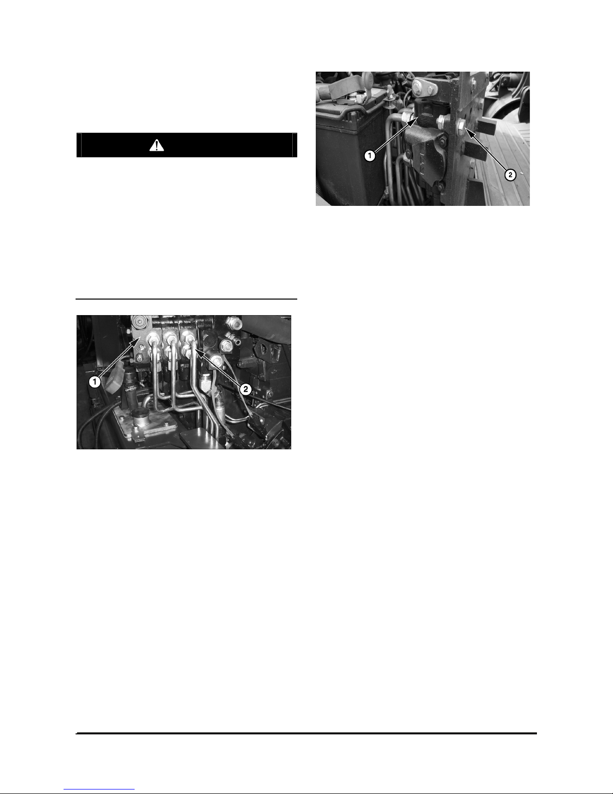
Remove And Install Tires And Rims
(Steer)
1. Put a hydraulic jack in position under the steer
axle.
2. Loosen nuts (1) that hold the tire and rim in place.
3. Lift the steer axle until the tire is clear of the
ground. Remove nuts (1). Remove the tire and rim.
NOTE : The following steps are for installation of the
tires and rims (steer).
4. Put the tire and rim in position on the hub.
5. Install nuts (1) that hold the tire and rim in place.
Tighten the nuts to a torque of 430
± 35 NIm
(318
± 25 lbIft).
6. Lower the steer axle and remove the hydraulic
jack.
Page 51
Vehicle Systems Disassembly & Assembly 49
Hydraulic Control Valves
Remove And Install Hydraulic Control
Valves
WARNING
Hydraulic oil under pressure can remain in the
hydraulic system after the engine and pump
have been stopped. Personal injury can result if
the pressure is not released before any work is
done to the hydraulic system. To prevent
possible personal injury, turn the engine off and
move the control levers to make sure the
hydraulic pressure is released before any fitting,
plug, hose or component is loosened, tightened,
removed or adjusted. Always move the lift truck
to a clean and level location away from the travel
of other machines.
NOTE : For purposes of reassembly, put
identification marks on all lines, tubes and hoses
before any disconnections are made.
1. Disconnect hydraulic lines (2) from control valve
(1).
2. Remove the cotter pins, washers and pins from
linkages.
3. Support control valve (1). Remove four bolts (2),
nut and control valve (1).
4. Install the control valve in the reverse order of
removal.
5. Fill the hydraulic tank to the correct level with fluid.
Refer to the Operation And Maintenance Manual
for further information.
Page 52
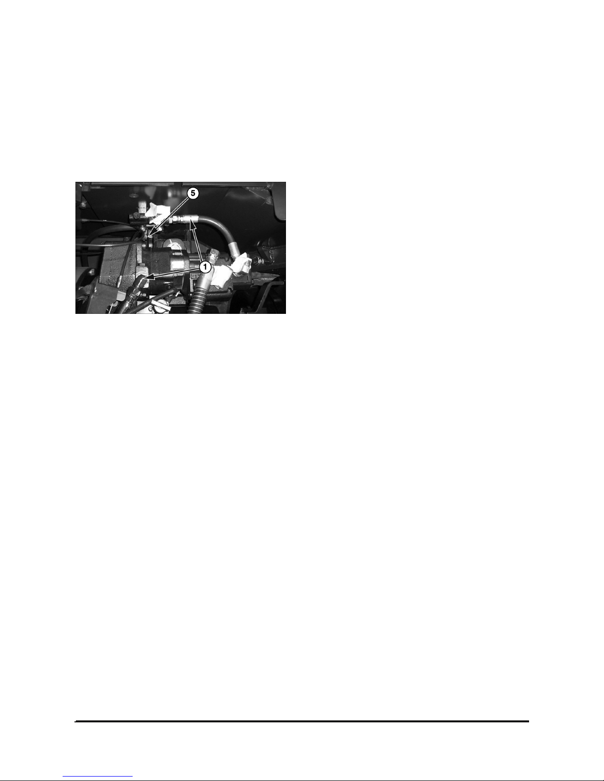
Vehicle Systems Disassembly & Assembly 50
Hydraulic Pump
Remove and Install Hydraulic Pump
Start By :
a. Remove counterweight.
1. Drain the oil from the hydraulic tank.
2. Disconnect three oil lines (1) from the pump
elbows.
3. Fasten a hoist to pump (5).
Remove bolts (4) that hold the pump in place.
Remove the pump and plate assembly.
The weight of the pump is 30 kg (132 lb).
NOTE: The following steps are for installation of the
hydraulic pump.
4. Inspect seals for damage. Install new seals, if
needed.
5. Fasten a hoist to pump (5). Put the pump and
plate assembly in position and install the bolts that
hold the pump in place. The weight of the pump is
30 kg (132 lb).
6. Connect three oil lines (1) to the pump elbows.
7. Fill the hydraulic tank with oil to the correct level.
See the Operation and Maintenance Manual.
End By :
a. Install counterweight.
Page 53
Vehicle Systems Disassembly & Assembly 51
General Instruction
Cleanliness
1.Cleanliness is the primary means of assuring
satisfactory hydraulic pump life.
Components such as flanges and covers are best
cleansed in soap and hot water, then air dried.
Gears should be washed in solvent, air dried, and
oiled immediately.
Certain cleaning solvents are flammable. Do not
allow sources of ignition in the area when using
cleaning solvents.
2.Protect all exposed surfaces and open cavities
from damage and foreign material.
Gear journals and gear faces are super finished.
Take care not to touch these surfaces after oil and
solvent.
Lubrication of moving parts
During assembly, all running surfaces (Bearing and
wear plate) must be lightly lubricated with a clean oil
or aerosol lubricant.
Tools required for assembly
1. Socket sets
2. Internal snap ring pliers
3. Shaft seal sleeve or clear tape
4. Torque wrench (200lbf ∙ft capacity)
5. Plastic hammer
6. Torque wrench box end adapters
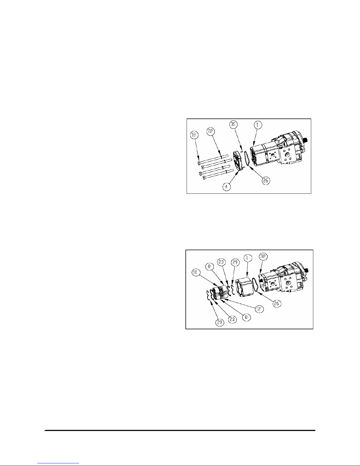
Disassembly Process
Rear section
Loosen and remove the clamp bolts (18) from rear
working section (1).
Related parts
Washer (22), Rear cover (4), Dowel pin(35),
Square-ring (26).
1. Remove driving gear (10), driven gear (12) with
thrust plate parts (8, 23, 29), keeping gear as
straight as possible, and working section (1) also.
Related parts
Back-up ring (29), O-ring (23), Thrust plate (8),
Working body (1), Square ring (26).
Page 54
Vehicle Systems Disassembly & Assembly 52
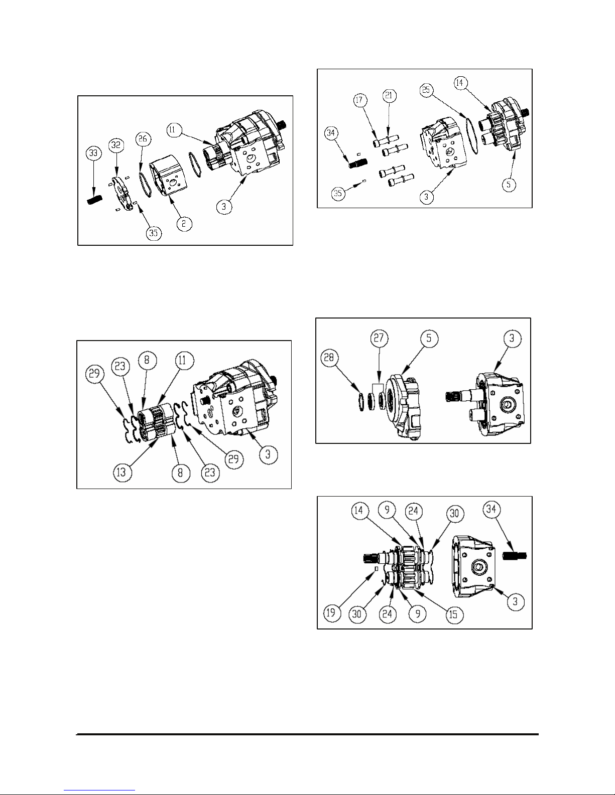
Center section
1. Remove through shaft (33) from driving shaft (11).
2. Remove the flange(32) and the working section
(2) with dowel pin (35).
Related parts
Square ring(26)
3. Remove driving gear (11), driven gear (13) with
thrust plate parts (8, 23, 29), keeping gear as
straight as possible, from first working body(3).
Related parts
Back-up ring (29), O-ring (23), Thrust plate (8).
4. Remove through shaft(34) from driving shaft(14).
5. Loosen and remove the clamp bolt(17) with
washer(21), and then remove the working
section(3) from mounting flange(5)
Related parts. Square ring(25), Dowel pin (35)
Front section
1. Remove the snap-ring (28) and shaft seal (27),
And then remove mounting flange (5) from
working section (3).
2. Remove driving gear(14), driven gear(15) with
through shaft(34) and thrust plate parts(9,24,30)
from the working body(3), keeping gear as straight
as possible,
Related parts
Plug (19), Back-up ring (30), O-ring (24), Thrust
plate (9).
Page 55
Vehicle Systems Disassembly & Assembly 53
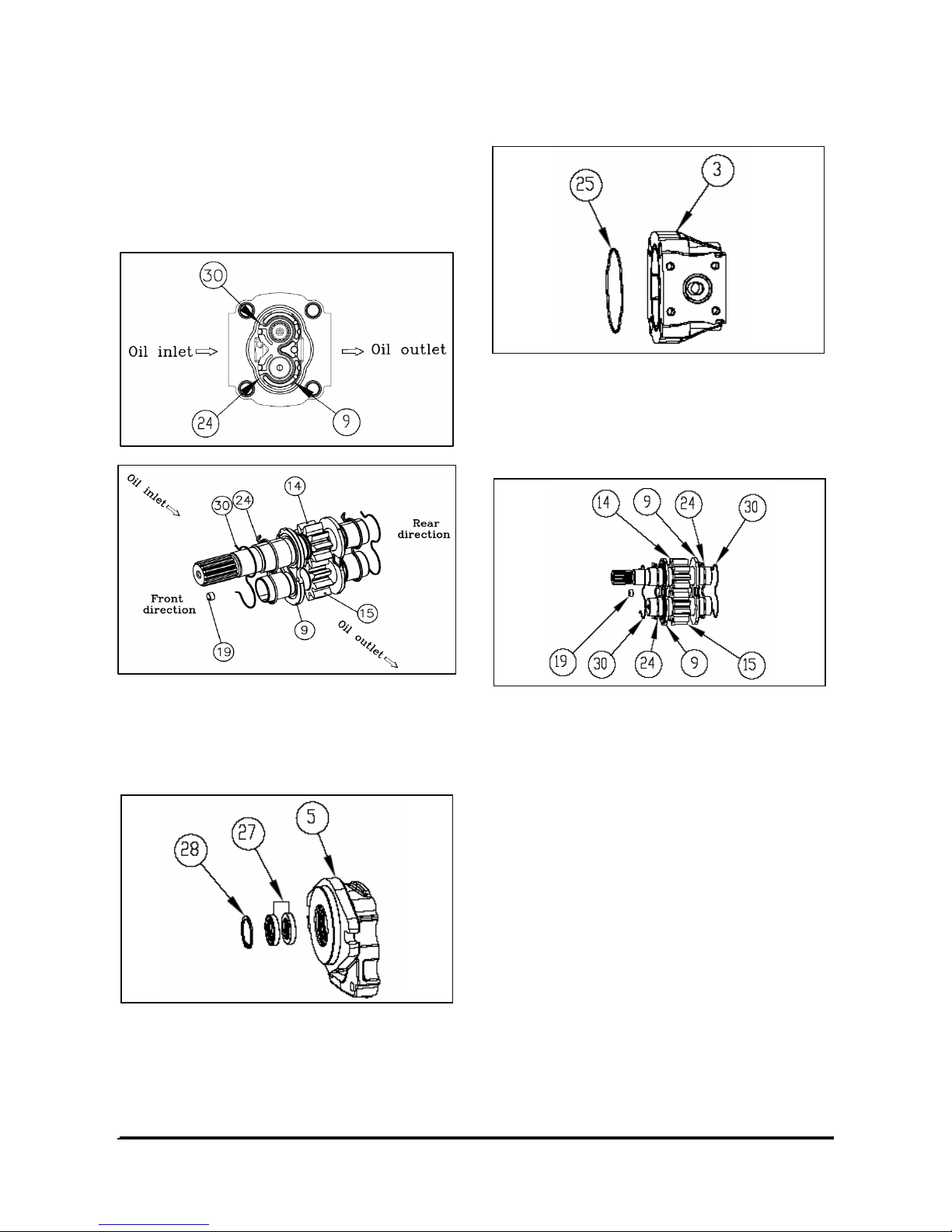
Reassembly Process
Information for assembly way of thrust plates
It is important that all of thrust plate parts in this
hydraulic pump should be assembled such as below
picture during reassembly. Picture 8, 9 show
assembling sequence and direction.
(9) Thrust plate (19) Plug
(14) Driving gear (24) O-ring
(15) Driven gear (30) Back-up ring
Front cover area
1. Insert the shaft seal (27) carefully and fit it inside
of mounting flange (5) with proper tool.
2. Fit the snap-ring(28) in pre-arranged position with
proper tool.
Center section
1. Fit the square ring (25) on the pre-arranged
groove of the working section (3).
Smear clean grease on the square ring (25) to
avoid drifting away of square ring from the
working section (3).
2. Locate the o-ring (24) on the groove pre-arranged
on the thrust plate (9).
3. Then, locate back-up ring (30) on the groove prearranged on the seals (9, 24) with plug (19).
Smear clean grease on the seal(24,30)
(The front and rear thrust plates and seals and
back-up ring are same.)
Page 56
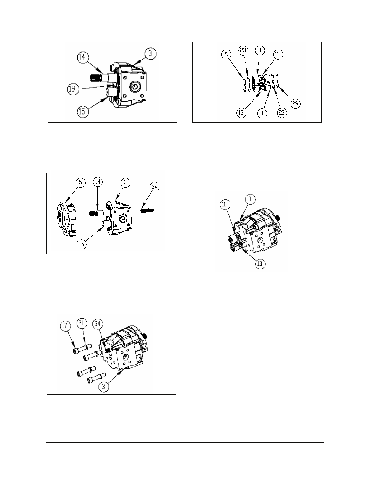
Vehicle Systems Disassembly & Assembly 54
4. Insert the driving gear (14) and driven gear (15)
into working section (3) while keeping the gears
straight.
Locate thrust plate(9+24+30) with care for the
direction
5. Locate the completed mounting flange (5+27+28)
to working section (3) while tacking care not to
give any damage on the shaft seal by edge of
shaft(14).
6. Insert the through shaft (34) to rear side of the
driving shaft (14).
7. Tighten the bolt (17) with washer (21) in a cross
pattern to torque valve of 140Nm.
8. Locate the o-ring (23) on the groove ore-arranged
on the thrust plate (8).
9. Then, locate back-up ring (29) on the groove prearranged on the seals (8, 23).
Smear clean grease on the seal(8,23)
(The front and rear thrust plates and seals and
back-up ring are same.)
10. Insert the driving shaft(11) and driven gear (13)
including the completed thrust plate(8+23+29)
into working section(3) while keeping the plate
straight.
Page 57
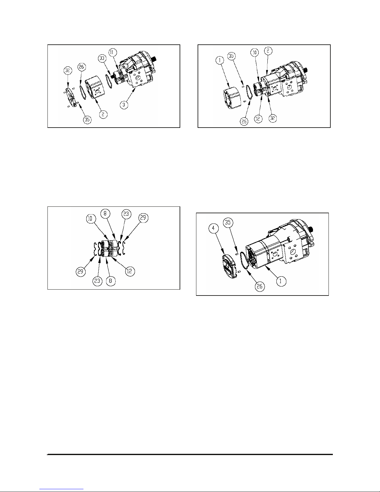
Vehicle Systems Disassembly & Assembly 55
11. Insert the through shaft (33) into driving shaft
(11), and then locate the working body (2) and
flange (32) after inserting the squaring ring (26)
to body (2).
Smear clean grease on the square ring (26) to
avoid drifting away of square ring from the
working body (2).
Rear section
1. Locate the o-ring (23) on the groove pre-arranged
on the thrust plate (8).
2. Then, locate back-up ring (29) on the groove prearranged on the seals (8, 23).
Smear clean grease on the seal(8,23)
(The front and rear thrust plates and seals and
back-up ring are same.)
3. Locate the driving gear(10) and driven gear(12)
with thrust plate parts(8+23+29) into working
section(2).
4. Insert the dowel pin(35) into the working section
(2) and then, locate the rear working section (1) to
working section (2) while keeping the gear straight.
Smear clean grease on the square ring (26) to
avoid drifting away of square ring from the rear
working section (1).
5. Locate the rear cover(4) after inserting the
square ring(26) and the dowel pin(35) into the rear
working section(1).
Smear clean grease on the square ring(26) to
avoid drifting away of square ring(26) from the
rear cover(4).
Page 58
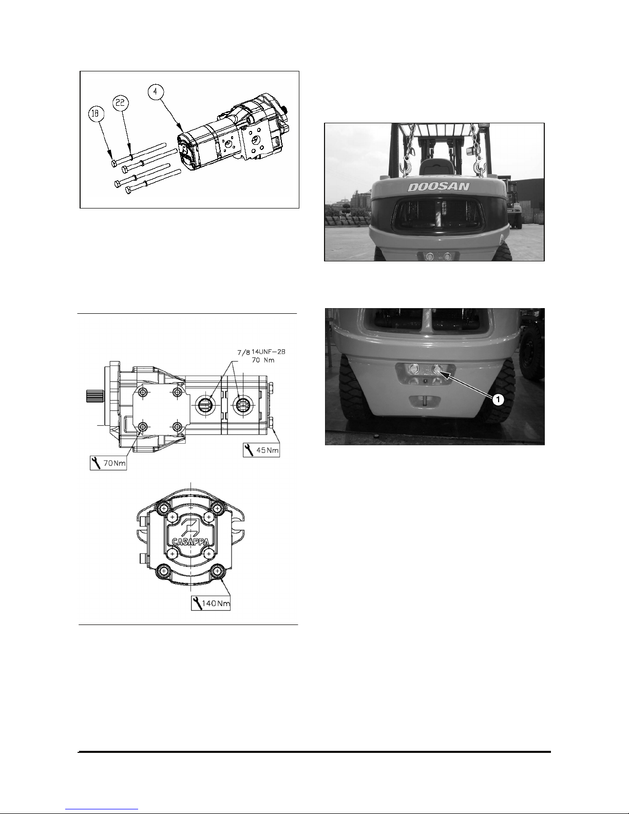
Vehicle Systems Disassembly & Assembly 56
6. Tighten the bolt (18) with washer (22) in a cross
pattern to torque valve of 45Nm.
Check that the pump rotate freely when the
driving shaft is turned by hand. If not a thrust plate
seal may be pinched.
Reference
PIC.23 Torque configuration for hydraulic pump
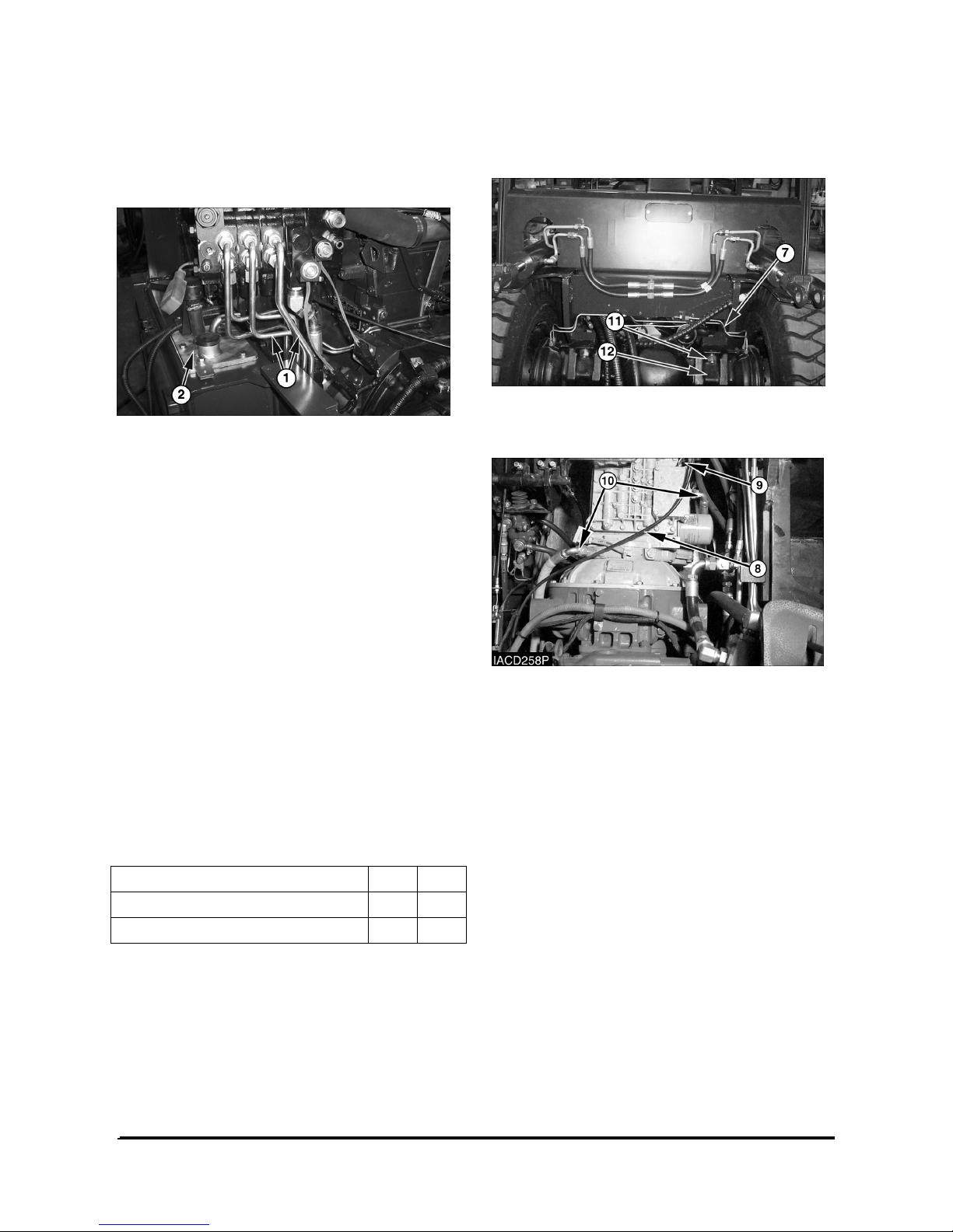
Counterweight
Remove And Install Counterweight
1. Install two eyebolts in the counterweight. Fasten a
hoist to the eyebolts as shown.
2. Remove two bolts (1), washers that hold the
counterweight to the frame. Remove the
counterweight. The weights of the different
counterweight go from a minimum of 1830 kg
(3630 lb) to a maximum of 3120 kg (5170 lb).
NOTE: The following steps are for installation of the
counterweight.
3. Install two eyebolts in the counterweight. Fasten a
hoist to the eyebolts.
4. Put the counterweight in position on the frame
and install bolts (1), washers that hold the
counterweight in place. Tighten torque : 600
± 50
N•m (442
± 37 lb•ft).
Page 59
Vehicle Systems Disassembly & Assembly 57
Hydraulic Oil Filter Assembly
Remove And Install Hydraulic Oil Filter
Assembly
1. Disconnect four oil lines (1).
2. Remove hydraulic tank cover (2).
3. Remove the oil filter from hydraulic tank cover.
NOTE: The following steps are for installation of the
hydraulic oil filter assembly.
4. Install the hydraulic oil filter assembly in position
on hydraulic tank cover.
5. Install the hydraulic tank cover (2) with six bolts
and washers.
6. Connect four oil lines (1).
7. Fill hydraulic oil tank to the correct level. See the
Operation and Maintenance Manual.
Drive Axle and T/M
Remove & Install Transaxle
Tools Needed A B
Stand 2
Link Bracket 1
Start By :
a. Remove mast *
b. Remove floor plate.
* Refer to the mast systems Disassembly &
Assembly section for further information.
1. Raise the machine until tires are approximately 1
to 2 inches off of the floor. Position the machine
on tooling (A).
2. Disconnect brake tubes (7) and parking cables
from drive axle.
3. Disconnect accel cable (8).
4. Disconnect wires (9) from solenoid valves and
wire from transmission temperature sender.
5. Disconnect two cooling hoses (10).
6. Loosen bolts (11) and remove drive axle
mounting bracket (12).
Page 60
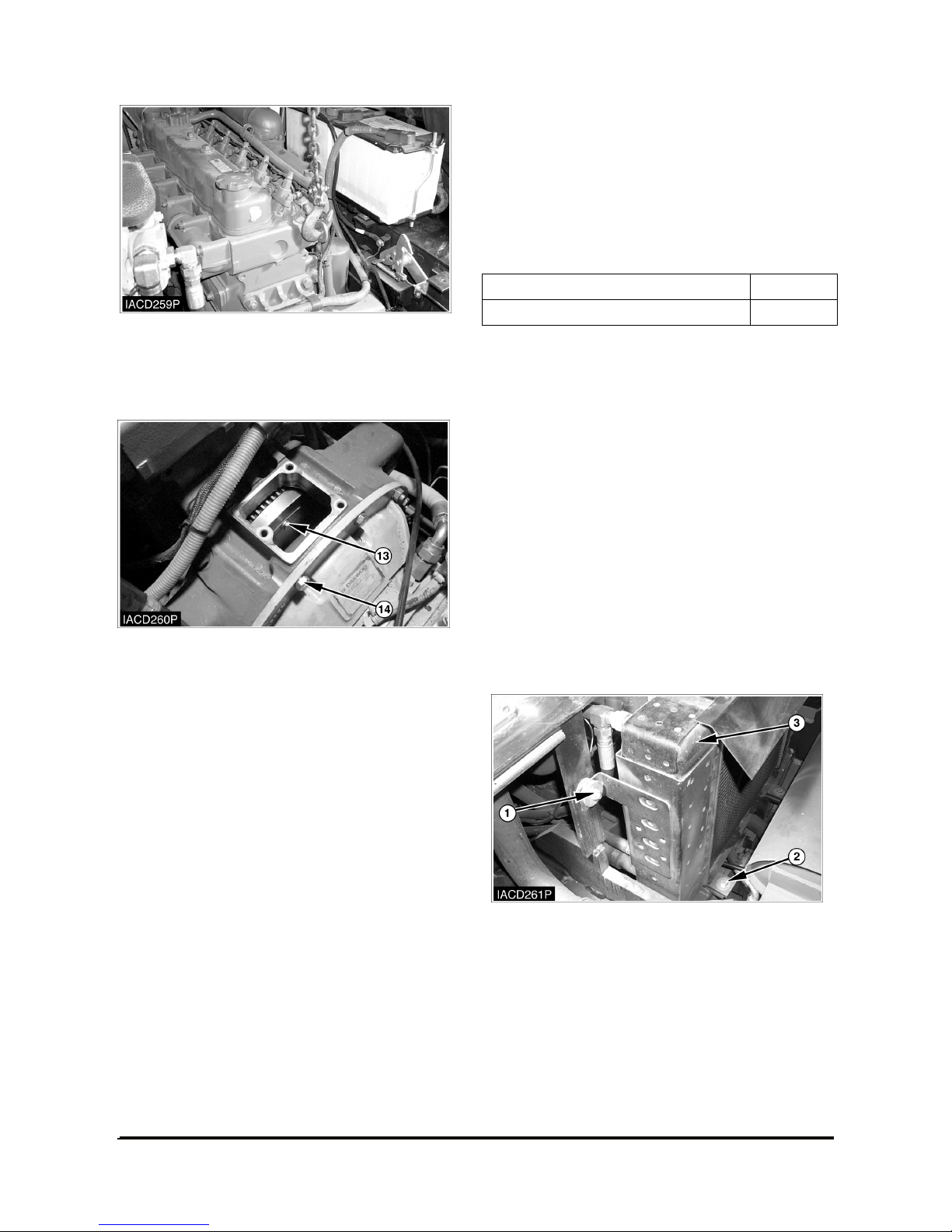
Vehicle Systems Disassembly & Assembly 58
7. Support the engine with a hoist and tooling (B).
8. Support transaxle assembly with a floor jack and
wood block.
9. Remove housing cover.
Remove bolts (13) that hold the converter to the
flywheel.
NOTE: At this point, make a final check to be sure
all removals and disconnections have been made
from the transaxle.
10. Remove bolts (14) and nuts from the converter
housing.
11. Use the floor jack to move transaxle assembly
from beneath the machine.
12. Install transaxle in the reverse order of removal.
13. Bleed the brake system.
Refer to the topic “Brake System Air removal” in
the Testing and Adjusting section of Vehicle
Systems.
14. Fill all fluids to their correct levels.
End By :
a. Install floor plate.
b. Install mast *
* Refer to the Mast System Disassembly &
Assembly Section for further information.
Engine
Remove & Install Engine
Tools Needed A
Link Bracket 1
NOTE: Procedures for LP gas and diesel engines
are all similar. The engine shown in the following
illustrations is for diesel engine.
Start By :
a. Remove overhead guard *
b. Remove hood (with seat) assembly *
c. Remove counterweight *
d. Remove floor plate.
e. Remove hydraulic control valve *
* Refer to the topics “Overhead Guard”, “Hood (with
seat) Assembly”, “Counterweight” and “Hydraulic
Control Valve” in this module.
1. Disconnect all hoses from radiator (3). Loosen
bolts (1) and (2) and remove radiator (3).
Page 61
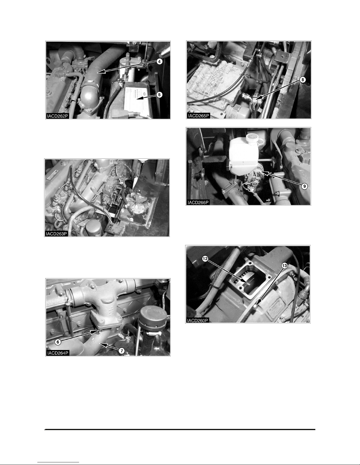
Vehicle Systems Disassembly & Assembly 59
2. Disconnect air intake hose (4).
3. Disconnect battery cables and remove battery (5)
and battery tray assembly.
4. Disconnect fuel lines from the engine.
5. Disconnect accel cable and engine stop motor
cable from the engine.
6. Loosen nuts (6) and disconnect exhaust tube (7).
7. Disconnect engine wire harness (8). Disconnect
wires from the alternator (9). To remove engine
from the truck, other wires or connectors not
shown should be disconnected.
8. Remove housing cover.
Remove bolts (12) that hold the converter to the
flywheel.
NOTE: At this point, make a final check to be sure
all removals and disconnections have been made
from the engine.
9. Support engine with a hoist and tooling (A).
Support transaxle with wood block.
10. Remove bolts (13) and nuts from the converter
housing.
Page 62
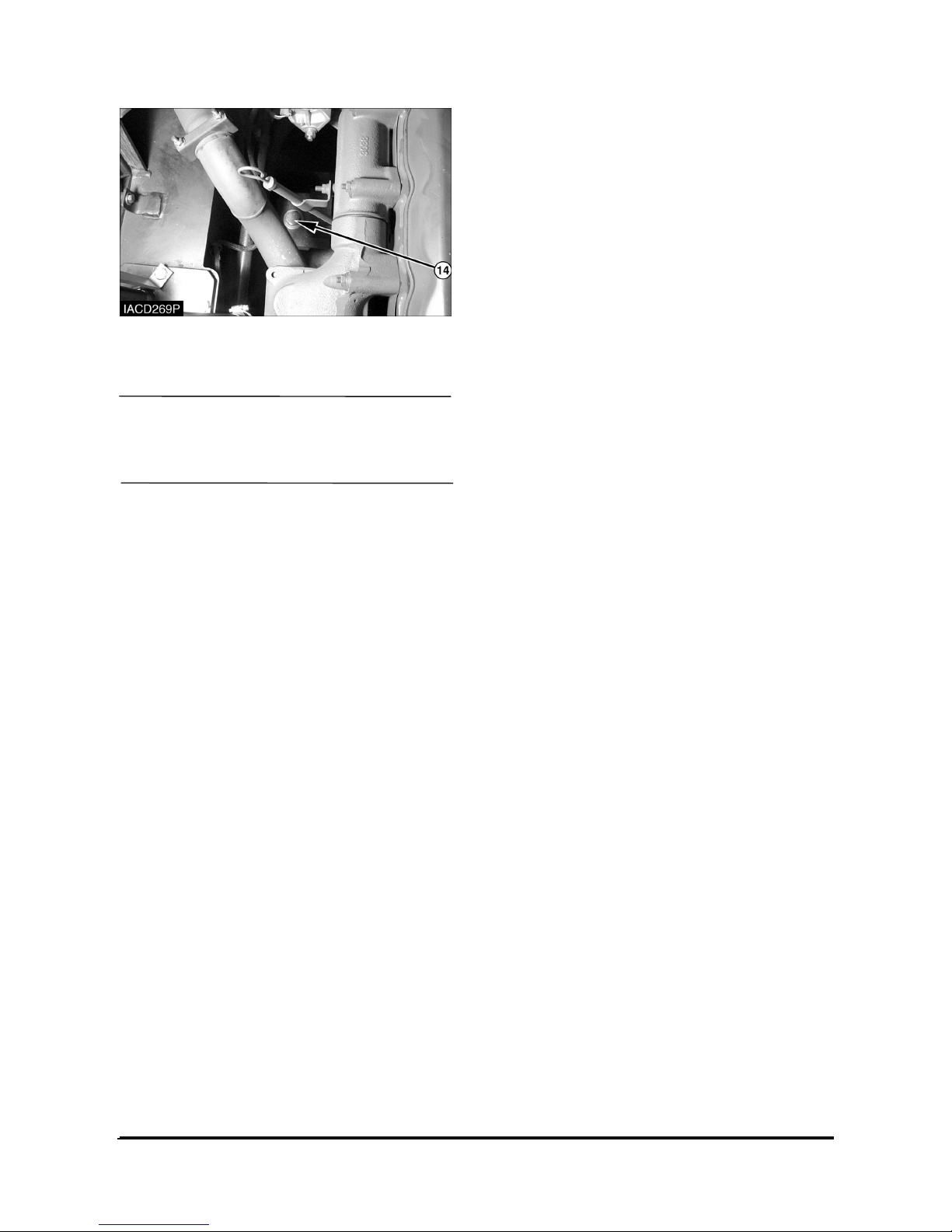
Vehicle Systems Disassembly & Assembly 60
11. Remove bolts (14) and nuts from two engine
mounts, located on each side of the engine.
NOTICE
Make sure the engine is supported underneath by
suitable wooden blocks. Failure to support engine
will result in possible damage.
13. Remove the engine with a hoist.
14. Install the engine in the reverse order of removal.
End By :
a. Install hydraulic control valve *
b. Install floor plate.
c. Install hood (with seat) assembly *
d. Install counterweight *
e. Install Overhead guard.*
* Refer to the topics “Hydraulic Control Valve”,
“Hood (with seat) Assembly”, “Counterweight” and
“Overhead Guard”.
 Loading...