

Page 1

SB2088E02
Sep. 2011
DE08TS Diesel Engine
Disassembly & Assembly
D100, D120, D150
D110S-5, D130S-5, D160S-5
Page 2

Page 3

Important Safety Information
WARNING
Most accidents involving product operation, maintenance and repair are caused by failure to observe basic safety
rules or precautions. An accident can often be avoided by recognizing potentially hazardous situations before an
accident occurs. Aperson must be alert to potential hazards. This person should also have the necessary training,
skills and tools to perform these functions properly.
Improper operation, Iubrication, maintenance or repair of this product can be dangerous and could result
in injury or death.
Do not operate or perform any Iubrication, maintenance or repair on this product, until you have read and
understood the operation, Iubrication, maintenance and repair information.
Safety precautions and warnings are provided in this manual and on the product. If these hazard warnings are not
heeded, bodily injury or death could occur to you or other persons.
The hazards are identified by the "Safety Alert Symbol" and followed by a "Signal Word" such as "WARNING" as
shown below.
The meaning of this safety alert symbol is as follows :
Attention! Become Alert! Your Safety is Involved.
The Message that appears under the warning, explaining the hazard, can be either written or pictorially presented.
Operations that may cause product damage are identified by NOTICE labels on the product and in this publication.
DOOSAN cannot anticipate every possible circumstance that might involve a potential hazard. The warnings in this
publication and on the product are therefore not all inclusive. If a tool, procedure, work method or operating
technique not specifically recommended by DOOSAN is used, you must satisfy yourself that it is safe for you and
others. You should also ensure that the product will not be damaged or made unsafe by the operation, Iubrication,
maintenance or repair procedures you choose.
The information, specifications, and illustrations in this publication are on the basis of information available at the
time it was written. The specifications, torques, pressures, measurements, adjustments, illustrations, and other
items can change at any time. These changes can affect the service given to the product.
Obtain the complete and most current information before starting any job. DOOSAN dealers have the most current
information available.
1 of 76
Page 4

Page 5

Index
Air Cleaner Assembly ...........................................24
Air Cleaner Elements.............................................25
Air Compressor (if equipped).................................72
Alternator ...............................................................12
Camshaft And Camshaft Bearing ..........................61
Connecting Rod Bearings......................................48
Cooling Water Pipe................................................41
Crankshaft..............................................................69
Crankshaft Pulley...................................................63
Cylinder Head ........................................................49
Cylinder Head Cover..............................................34
Cylinder Liners.......................................................57
Electric Starting Motor............................................11
Engine And Transmission........................................5
Exhaust Manifold ...................................................33
Fan Assembly ........................................................26
Fan Belts................................................................26
Flywheel.................................................................64
Flywheel Housing...................................................68
Fuel Filter...............................................................18
Fuel Injection Lines................................................17
Fuel Injection Nozzle Assembly.............................20
Fuel Injection Pump ...............................................13
Fuel Pump..............................................................19
Fuel Strainer ..........................................................18
Intake Manifold.......................................................31
Muffler....................................................................22
OIl Cooler...............................................................39
Oil Filter..................................................................38
Oil Pan ...................................................................34
Oil Pump ................................................................42
Pistons ...................................................................53
Radiator .................................................................28
Rocker Shaft ..........................................................46
Rocker Shaft And Push Rods ................................45
Timing Gear Case..................................................60
Timing Gear Case Cover .......................................58
Timing Gears .........................................................58
Water Pump...........................................................35
Water Temperature Regulator ...............................27
Disconnect batteries before performance of any
service work
WARNING
Page 6

Page 7
Engine
2
5
4
7
6
3
8
1
Remove Engine And
Transmission
A10999 & D40999 - 02
Tools Needed A
Link Bracket 1
IEED002P
Start By :
a. Remove overhead guard.*
Remove floorplate.*
b.
Remove hood.*
c.
Remove air cleaner.
d.
e. Remove universal joint.*
This operation is in the Vehicle Systems,
*
Disassembly And Assembly Manual.
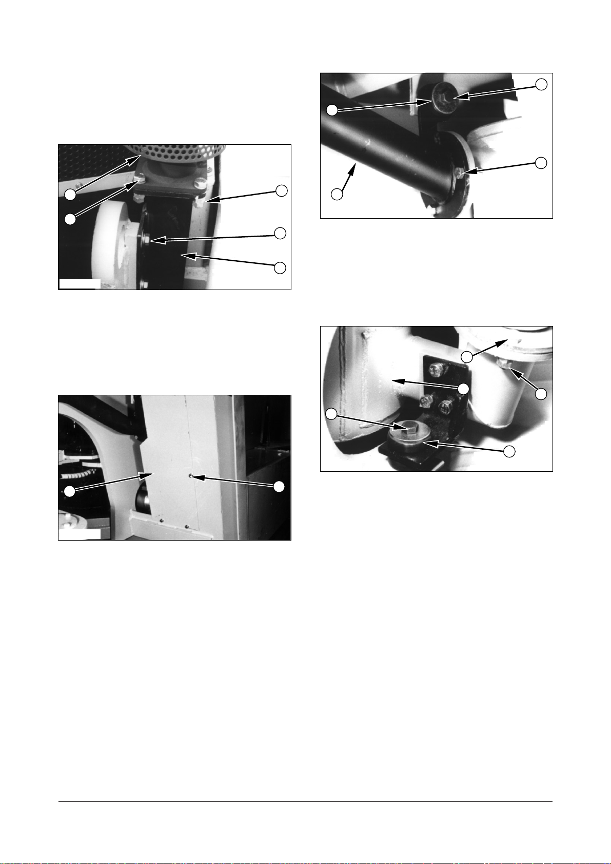
1. Drain the coolant from the radiator.
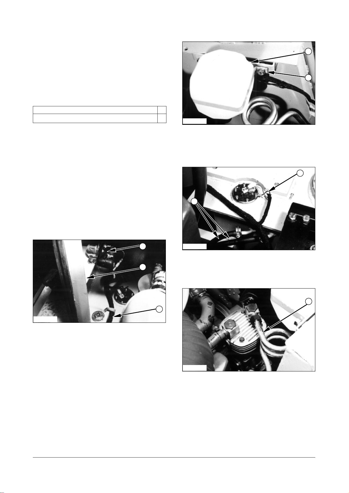
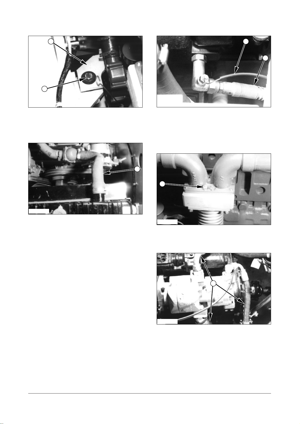
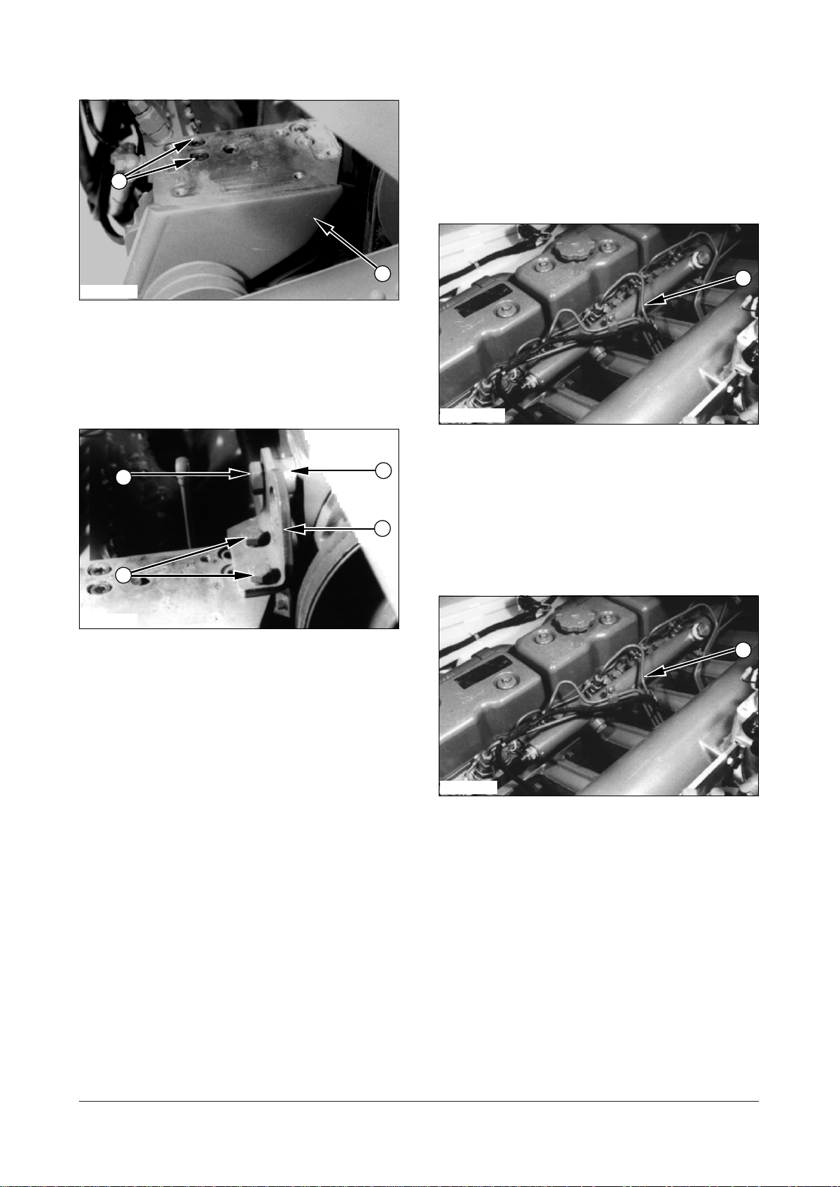
5. Remove bolts (4), washers and nuts that hold
coolant reservoir on the frame. Set coolant
reservoir (5) aside.
IEED003P
6. Disconnect two hoses (6) from the fuel tank.
7. Disconnect wiring harness (7) from fuel sender.
IEED001P
2. Remove engine harness assembly (1) from the
clips of bonnet assembly (3).
3. Remove screws, washers and circuit breaker (2)
from bonnet assembly (3).
4. Remove bolt and washer that hold bonnet
assembly. Remove bonnet assembly (3) from the
frame.
DE08TS Diesel Engine Disassembly and Assembly
5 of 76
IEED004P
8. Remove tube (8) from the tube of air compressor
(if equipped).
Page 8
IEED005P IEED008P
9
11
14
15
12
10
13
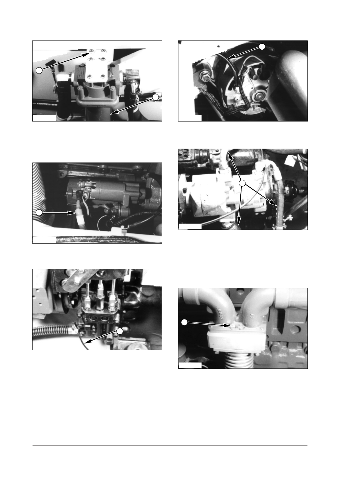
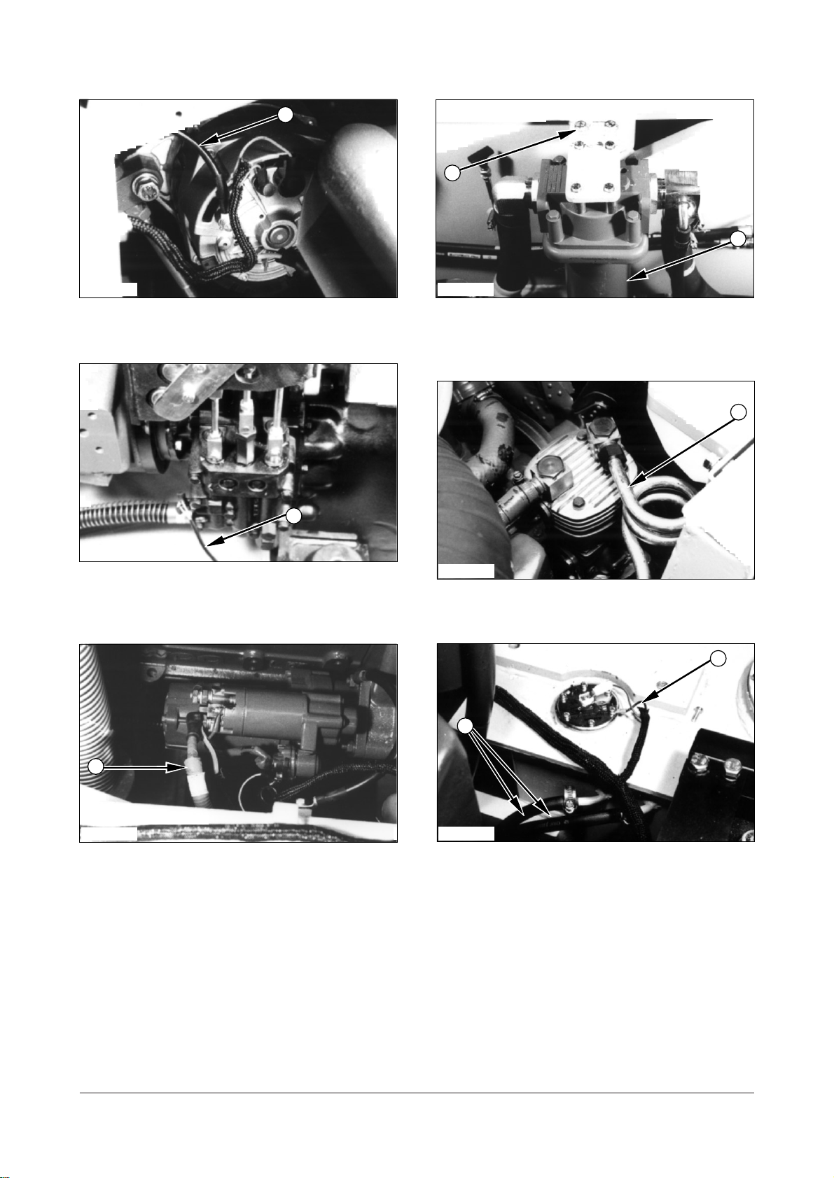
9. Remove two bolts washers (9) and hydraulic filter
assembly (10). Set hydraulic filter assembly (10)
aside.
IEED006P
10. Disconnect battery cable (11) from the starting
motor.
12. Disconnect ground cable (13) from the alternator.
IEED009P
13. Disconnect three hoses (14) from the hydraulic
pump.
NOTE : Plug and cap all hydraulic connectors and hoses
to avoid debris and contamination from entering the
system.
IEED007P
11. Disconnect transmission neutral switch connector
IEED010P
(12).
14. Remove bolts (15) and washers that hold the
muffler expansion on exhanst manifold of the
engine.
DE08TS Diesel Engine Disassembly and Assembly
6 of 76
Page 9
IEED011P IEED014P
17
16
21
18
22
A
20
19
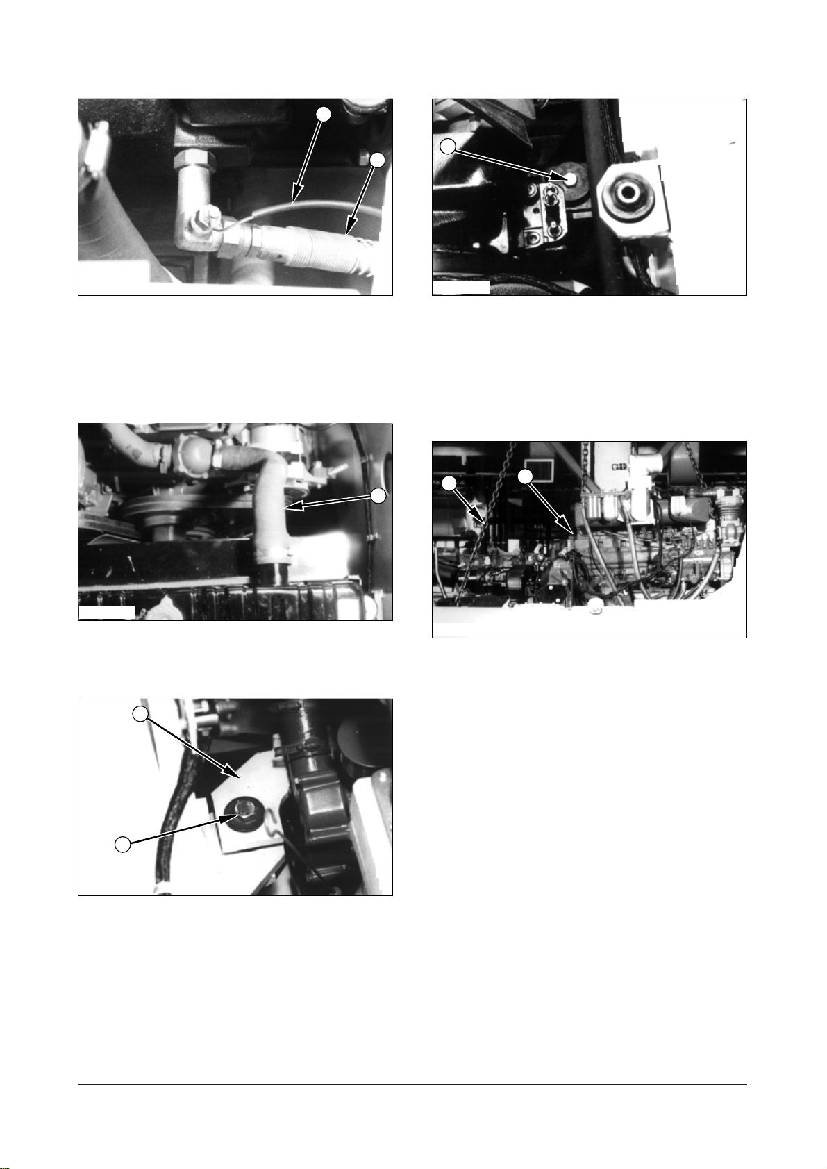
15. Disconnect two transmission cooling hoses (16)
from the transmission.
16. Disconnect transmission oil temperature switch
wiring (17).
IEED012P
17. Disconnect two engine cooling hoses (18 ) from
the engine.
19. Remove bolts (21), washers and nuts from the
two transmission support.
NOTE : At this point, make a final check to be sure all
removals and disconnections have been made from
the engine and the transmission.
IEED015P
20. Install the tool (A) to the transmission. Fasten tool
(A) to the engine and transmission as shown.
21. Remove engine and transmission (22) from the
lift truck.
22. Put the engine and transmission on an
acceptable engine stand. Remove tool (A).
IEED013P
18. Remove bolts (19), washers, nuts from the two
engine support (20), one on both side of the
engine.
DE08TS Diesel Engine Disassembly and Assembly
7 of 76
Page 10
IEED016P IEED017P
25
23
A
22
24
25
23
24
21
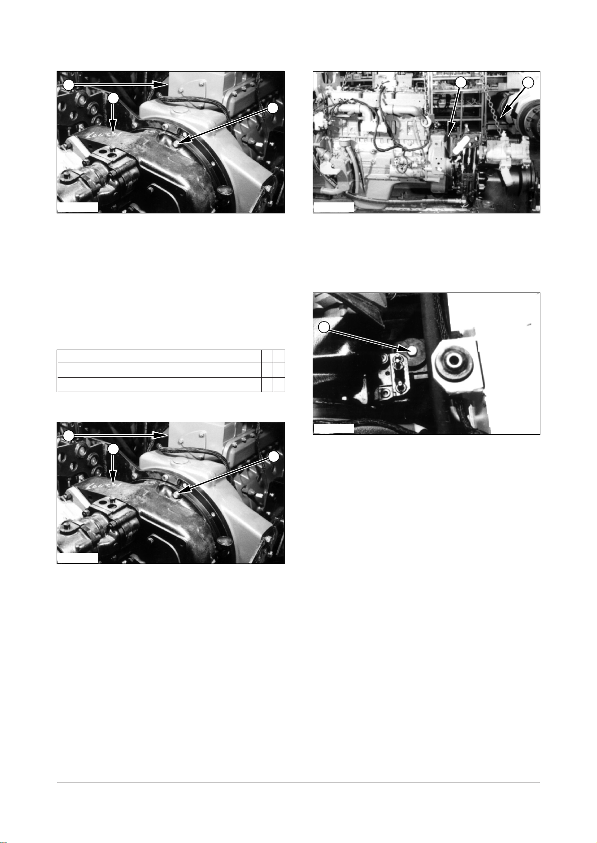
23. Support transmission (24) with fasten a strap and
remove twenty bolts(23) and washers. Remove
transmission (24) from engine (25).
Install Engine And Transmission
A10999 & C40999 - 03
Tools Needed A B
Link Bracket 1
Eye Bolt 1
3. Install the tool (A) to the transmission.
4. Fasten tool (A) to engine and transmission (22) as
shown.
IEED014P
5. Put the engine and transmission in position on the
lift truck. Make an alignment of supports with the
frame.
6. Install bolts (21), washers and nuts that hold the
transmission support to the frame.
Tightenbolts (21) to atorque of
(540
590 lbft).
730800 Nm
IEED016P
1. Put transmission (24) in position in engine (25).
2. Install bolts (23) and washers that hold
transmission to the engine. Tighten bolts (23) to
torque of
DE08TS Diesel Engine Disassembly and Assembly
55 10 Nm (40 7 lbft).
8 of 76
Page 11
IEED013P
20
19
18
17
16
15
14
IEED011P
7. Install bolts (19), washers and nuts that hold
engine support (20) to the frame. Tighten bolts (19)
to a torque of
IEED012P
280 Nm (205 lbft).
8. Connect two engine cooling hoses (18) and tighten
the hose clamps.
9. Connect two transmission cooling hoses (16) to
transmission.
10. Connect transmission oil temperature switch
connector (17).
IEED010P
11. Install bolts (15) and washers that hold the muffler
expansion to exhaust manifold of the engine.
IEED009P
12. Connect three hydraulic hoses (14) to the
hydraulic pump.
DE08TS Diesel Engine Disassembly and Assembly
9 of 76
Page 12
IEED008P
13
11
9
10
8
7
6
12
IEED005P
13. Connect ground cable (13) to the alternator.
IEED007P
14. Connect transmission neutral switch connector
(12).
16. Put hydraulic filter assembly (10) in position on
the frame. Install bolts (9) and washers.
IEED004P
17. Install tube (8) to the air compressor (if
equipped).
IEED006P
IEED003P
15. Connect battery cable(11) to the starting motor.
18. Connect wiring harness (7) to the fuel sender.
19. Connect two fuel hoses (6) and tighten the hose
clamp.
DE08TS Diesel Engine Disassembly and Assembly
10 of 76
Page 13
Electric Starting Motor
1
2
4
3
5
4
2
3
1
WARNING
Remove Electric Starting Motor
A61564 - 02
IEED002P
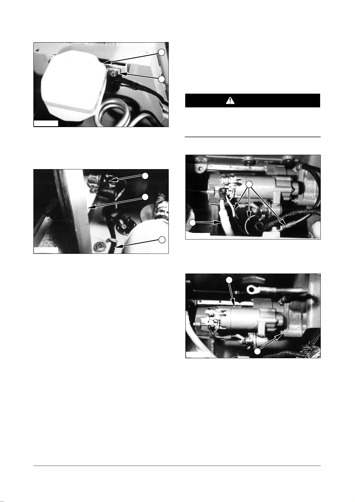
20. Put the coolant reservoir with bracket (5) in
position on the frame. Install bolts (4) and
washers that hold coolant reservoir (5).
IEED001P
21. Put bonnet assembly (3) in position on the frame.
Install the bolts and washers. Tighten the bolts to
a torque of
200 N..m (150 lb..ft).
Disconnect the battery before the starting motor
is removed
IEED018P
1.
Put identification on the starting motor and
solenoid wires. Disconnect wirings (1) and battery
cable (2).
22. Install the screws and washers that hold circuit
breaker (2).
23. Clear engine harness assembly (1).
24. Fill the cooling system. See the Maintenance
Guide for the correct level.
End By :
a. Install universal joint.
b. Install air cleaner.
c. Install hood.
d. Install floorplate.
e. Install overhead guard.
IEED019P
2. Remove mounting nuts (3) and then remove
starting motor (4) from the lift truck.
DE08TS Diesel Engine Disassembly and Assembly
11 of 76
Page 14
Install Electric Starting Motor
1
54653
2
6
4
3
1
2
A61564 - 03
IEED019P
Alternator
Remove Alternator B31018 - 02
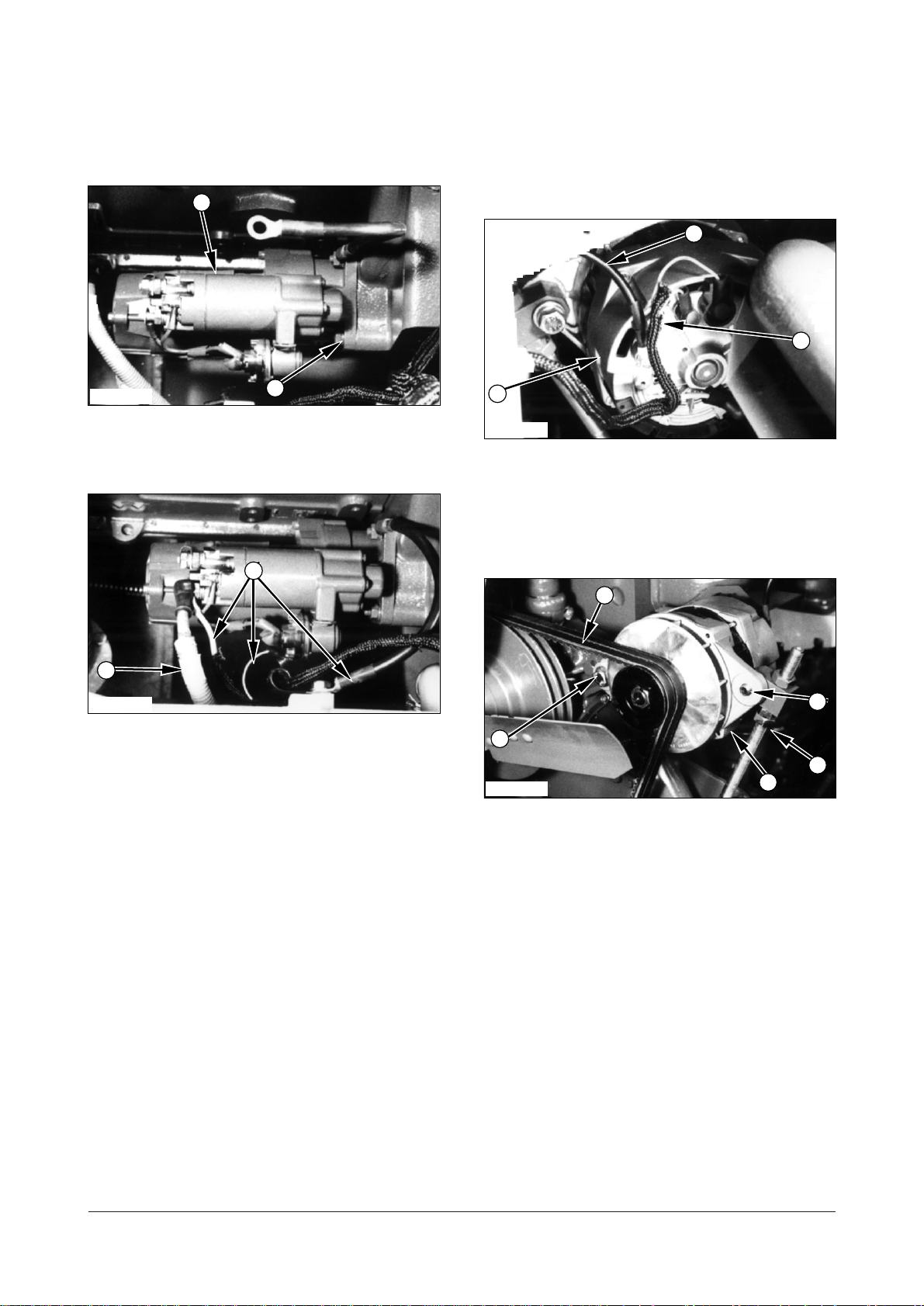
1. Put starting motor (4) in position on the flywheel
housing and install nuts (3) that hold it.
IEED018P
2. Connect wirings (2) to the starting motor and
solenoid. Connect battery positive cable (1).
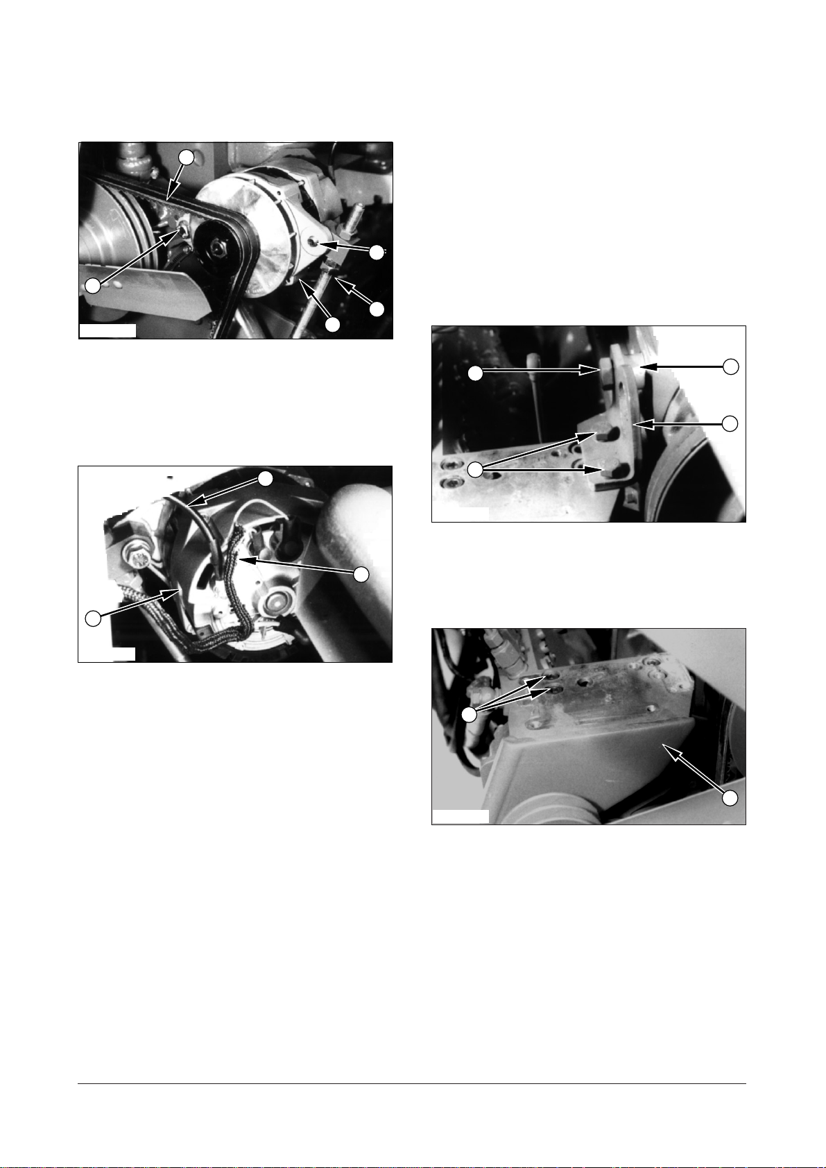
IEED020P
1. Put identification on all wires (1) and the
disconnect them from alternator (6).
2. Disconnect ground cable (2) from alternator (6).
IEED021P
3. Loosen nuts (4) and then remove belt (3) from the
alternator.
4. Remove bolts (5) from the alternator’s bracket to
remove alternator (6).
DE08TS Diesel Engine Disassembly and Assembly
12 of 76
Page 15
Install Alternator B31018 - 03
1
6
5
3
4
1
2
6
2
546
5
3
IEED021P
1. Put alternator (6) in position on its bracket and
install bolts (5) that hold it.
2. Install fan belt (3) on the alternator and tighten nuts
(4).
Fuel Injection Pump
Remove Fuel Injection Pump
A25663 - 02
Start By :
a. Remove air compressor (if equipped).
b. Remove intake manifold.
IEED020P
3. Connect all wires (1) to their respective positions.
4. Connect ground cable (2) to alternator (6).
IEED022P
1. Remove two bolts (1) and washers.
2. Remove bolt (2), washers, spacer (3) and lifting
bracket (4).
IEED166P
3. Remove bolts (5) and washers that hold the
tension adjusting bracket on the timing gear case.
4. Remove the idle pulley and V-belt tension
adjusting bracket assembly (6) and gasket.
Discard the gasket.
DE08TS Diesel Engine Disassembly and Assembly
13 of 76
Page 16
IEED023P
12
8
7
9
1414141513
10
11
9
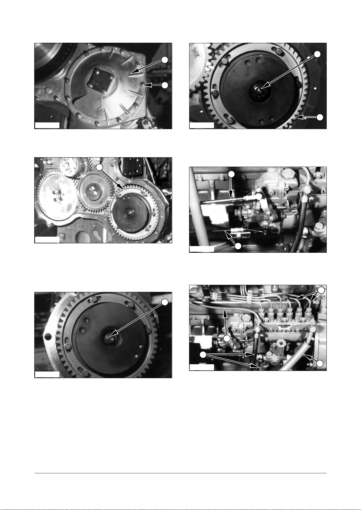
IEED118P
5. Remove bolts (7), washers and cover (8).
IEED024P
6. Make an alignment of the timing marks on fuel
injection pump gear (9) and the idle gear or put a
mark of identification on the gears for correct
installation.
8. Remove nut (11) and injection pump coupling and
gear (9) from the injection pump.
IEED025P
9. Disconnect accel rod (12) and engine stop cable
(13).
IEED026P
IEED117P
10. Disconnect five hoses (14) and tubes (15) from
7. Remove nut (10) from the injection pump coupling.
DE08TS Diesel Engine Disassembly and Assembly
14 of 76
the injection pump.
Page 17
17
IEED027P
16
16
18
17
9
11. Remove four nuts (16) and washers that hold the
injection pump in place. Remove the gasket and
discard it.
Install Fuel Injection Pump
A25663 - 03
IEED028P
1. Install the new gasket in position on the timing
gear case. Put fuel injection pump (17) in position
on the timing gear case.
IEED028P
12. Support injection pump (17). Remove two bolts
(18) and washers that hold injection pump (17) on
the block. Remove injection pump (17).
IEED024P
2. Make sure the timing marks or the marks that were
put on the fuel injection pump gear (9) and the idle
gear are in alignment.
IEED027P
3. Install four nuts (16) and washers that hold the fuel
injection pump on the timing gear case.
DE08TS Diesel Engine Disassembly and Assembly
15 of 76
Page 18
141414
15
12
13
18
8
7
10
IEED118P
11
9
IEED028P
4. Put the fuel injection pump drive coupling and gear
(9) in position. Make an alignment of the key and
the groove (slot) in the coupling.
5. Install nut (11) that hold the injection pump drive
coupling and gear (9) in place. Tighten nut (11) to
a torque of
IEED117P
130 Nm (96 lbft).
6. Install nut (10) into the injection pump coupling.
8. Install bolts (18) and washers that hold the
injection pump on the block.
IEED026P
9. Connect three hoses (14) and tube (15) to the
injection pump.
IEED025P
10. Connect accel cable (12) and engine stop cable
IEED023P
(13) to the injection pump.
7. Install cover (8), bolts (7) and washers.
DE08TS Diesel Engine Disassembly and Assembly
16 of 76
Page 19
1
1
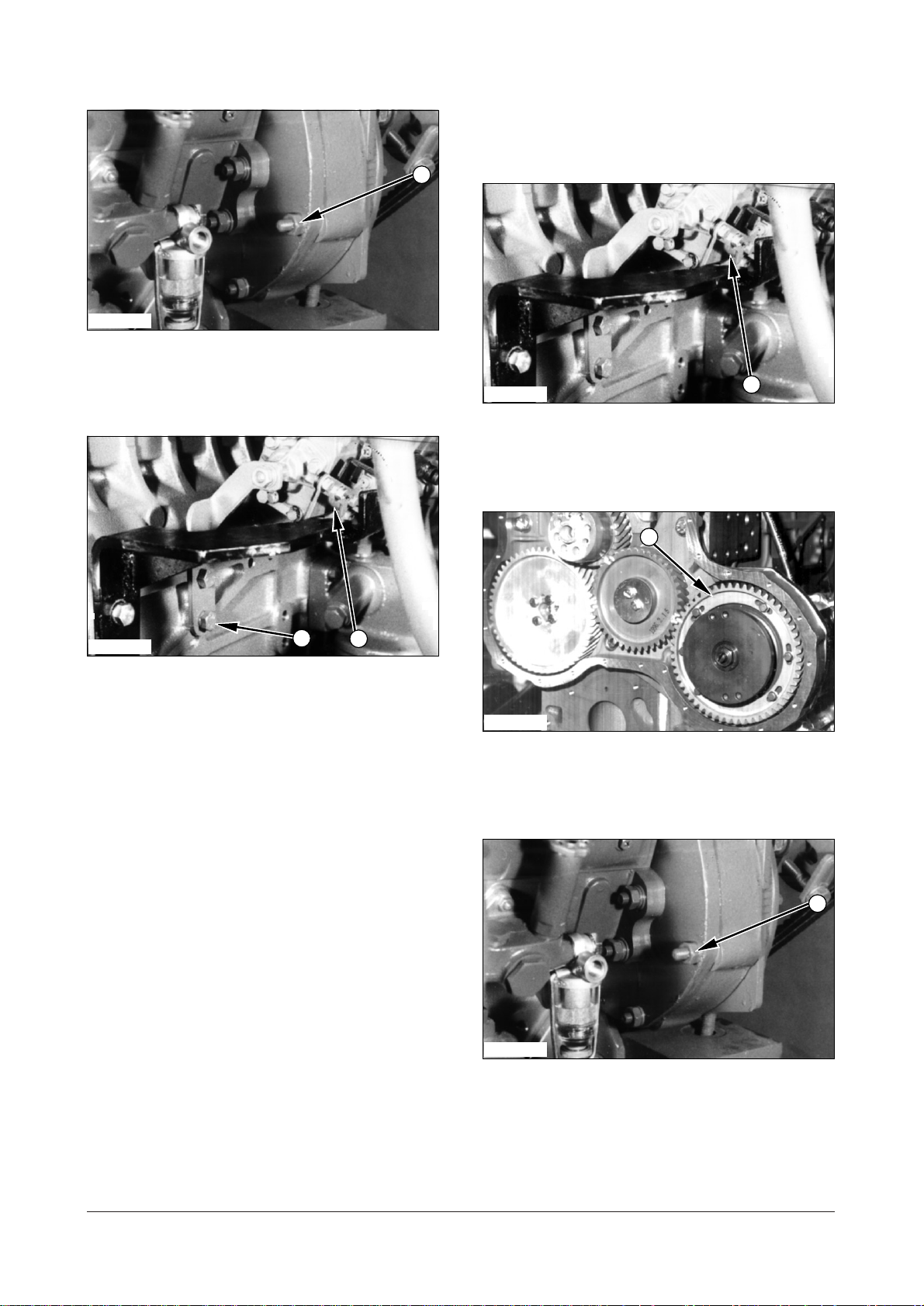
IEED166P
5
6
3
4
1
2
11. Install the new gasket on the timing gear case.
12. Put the idle pulley and V-belt tension adjusting
bracket assembly (6) on the timing gear case and
install bolts (5) and washers.
Fuel Injection Lines
Remove Fuel Injection Lines
A23525 - 02
IEED029P
1. Disconnect fuel injection lines (1) from the fuel
injection nozzle assemblies and the fuel injection
pump.
IEED022P
13. Install lifting bracket (4), spacer (3), washers and
bolts (2) on the block.
14. Install two bolts (1) and washers.
End By :
a. Install air compressor (if equipped).
b. Install intake manifold.
Install Fuel Injection Lines
A23525 - 03
IEED029P
2. Connect fuel injection lines (1) to the fuel injection
pump and the fuel injection nozzle assemblies.
Tighten the fuel line nuts toa torque of
16 to20 Nm (12 to 15 lbft).
DE08TS Diesel Engine Disassembly and Assembly
17 of 76
Page 20
Fuel Filter
2
1
3
4
1
2
2
1
Remove Fuel Filter A21357SE - 02
Fuel Strainer
Remove & Install Fuel Strainer
A21357PR - 01
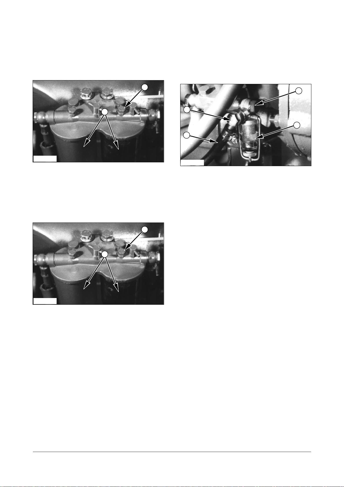
IEED030P
1. Loosen bolt (1). Remove bowl (2).
2. Remove fuel filter.
Install Fuel Filter A21357SE - 03
IEED030P
1. Install a new gasket in the filter bowl.
IEED031P
1. Remove bolt (1) and washers and disconnect fuel
line (2) that connected the fuel tank.
2. Remove bolt (3), washers and fuel strainer (4) from
the injection pump.
3. Install fuel strainer (4) in reverse order of removal.
2. Put a new fuel filter element in position.
3. Put filter bowl (2) in position and tighten bolt (1)
that holds the bowl in position.
DE08TS Diesel Engine Disassembly and Assembly
18 of 76
Page 21
Fuel Pump
2
1
2
1
3
4
3
4
Remove Fuel Pump A21663 - 02
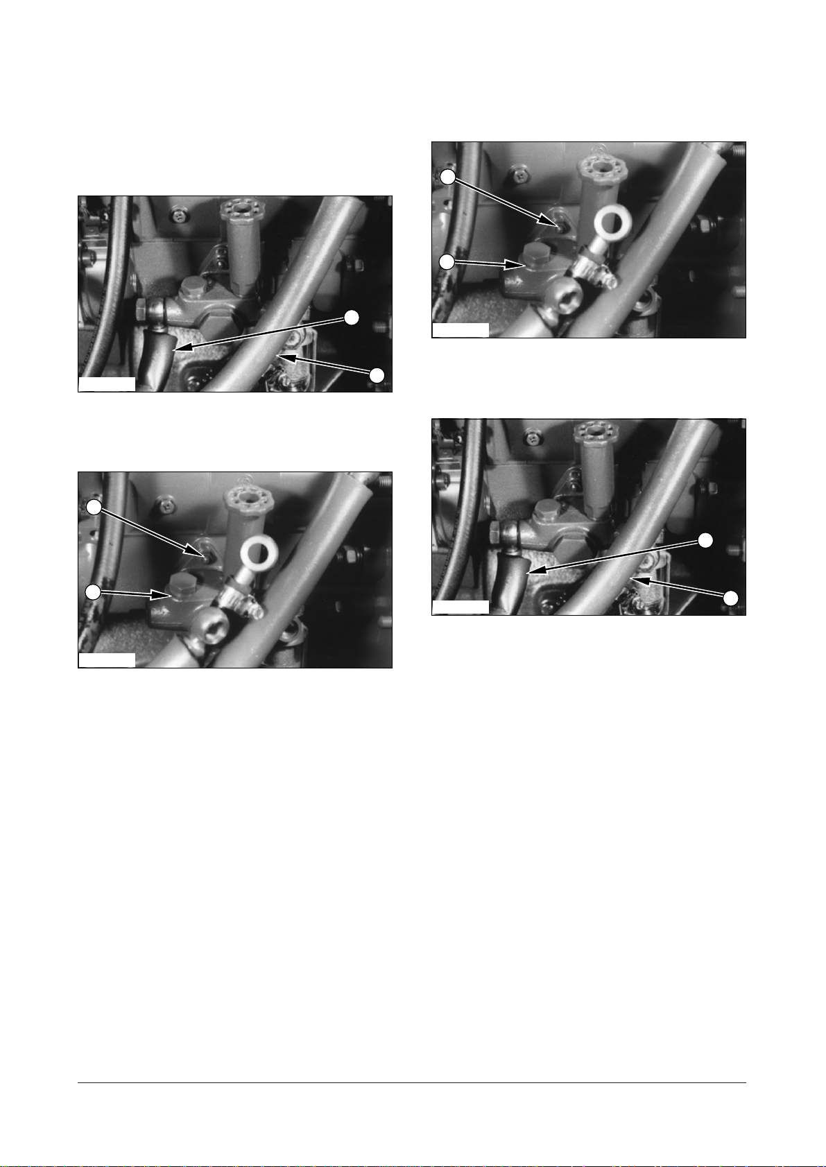
IEED032P
1. Disconnect fuel inlet line (1) and fuel outlet line (2)
from the fuel pump.
Install Fuel Pump A21663 - 03
IEED033P
1. Put fuel pump (4) in position on the engine block
with nuts (3) that hold it.
IEED033P
2. Remove three nuts (3) that hold fuel pump (4) to
the injection pump. Remove fuel pump (4).
IEED032P
2. Connect fuel outlet line (2) and fuel inlet line (1) to
the fuel pump.
DE08TS Diesel Engine Disassembly and Assembly
19 of 76
Page 22
Fuel Injection Nozzle
1
1
2
3
2
3
Assembly
Remove Fuel Injection Nozzle
Assembly A28999 - 02
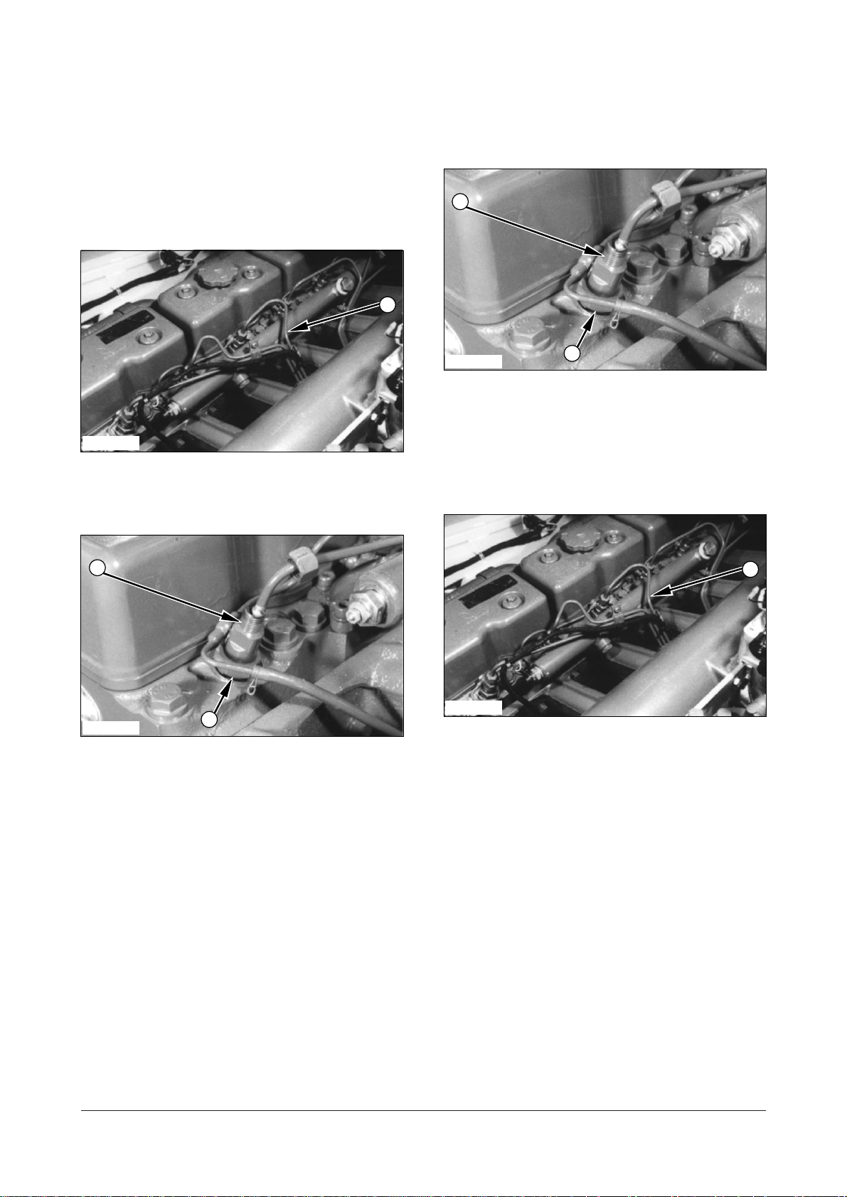
IECD029P
1. Disconnect fuel lines (1) from the fuel injection
nozzles.
Install Fuel Injection Nozzle
Assembly A28999 - 03
IEED034P
1. Install the new seal rings in the nozzle hole of the
cylinder head.
2.Put fuel injection nozzles (2) in position. Install nuts
(3) and tighten them to a torque of
(52
7 lbft).
7010 Nm
IEED034P
2. Remove nuts (3) and then remove fuel injection
nozzles (2).
3. Remove the seals from the nozzle holders of the
cylinder head and discard it.
IEED029P
3. Connect fuel lines (1) to the injection nozzles and
then tighten the nuts to a torque of
30 Nm (22 lbft).
DE08TS Diesel Engine Disassembly and Assembly
20 of 76
Page 23

Disassemble & Assemble Fuel
1
1
6
4
2
3
5
7
6
4
2
3
5
7
Injection Nozzle Assembly
A28999 - 06
Start By :
a. Remove fuel injection nozzle assembly
IEED035P
1. Remove union nut (1) from the nozzle assembly.
IEED036P
4. Install shims (7), spring (6), guide (5) and
intermediate washer (4) to the nozzle holder.
5. Install needle valve (3) into fuel nozzle (2) and
install the fuel nozzle.
IEED036P
2. Remove fuel nozzle (2), needle valve (3),
intermediate washer (4), guide (5), spring (6) and
shims (7) from the nozzle holder.
3. Check all parts for damage. If damaged, use new
parts for replacement.
NOTE : The following steps are for assembling the
fuel injection nozzle assembly.
IEED035P
6. Install union nut (1) and tighten to a torque of
7010 Nm (527 lbft).
End By :
a. Install fuel injection nozzle assembly.
DE08TS Diesel Engine Disassembly and Assembly
21 of 76
Page 24
Muffler
2
8
15
12
11
14
13
5
9
10
4
5
6
7
3
1
Remove Muffler A32570 - 02
IEED037P
1. Remove four bolts (1), washers and nuts (2) that
hold muffler tube assembly (3) on tube assembly
(5).
2. Remove two bolts (4) and washers that hold tube
assembly (5) on the frame.
IEED039P
4. Remove three bolts (8), washers and nuts.
5. Support tube assembly (5) and remove bolt (9),
washers, rubber mounts (10), shims and nuts that
hold tube assembly (5) on the frame. Remove tube
assembly (5).
IEED038P
3. Remove five bolts (6), washers and cover (7) from
the frame.
IEED040P
6. Remove three bolts (11), washers and nuts (12).
7. Remove bolt (13), washers, rubber mounts (14),
shims and nuts that hold mount bracket of muffler
assembly (15) on the frame. Remove muffler
assembly (15).
DE08TS Diesel Engine Disassembly and Assembly
22 of 76
Page 25

Install Muffler A32570 - 02
15
12
111413
8
5
9
10
2
4
5
3
1
6
7
IEED038P
IEED040P
1. Put the muffler assembly (15) in position on the
frame. Install bolt (13), washers, rubber mounts
(14), shims and nuts that hold muffler assembly
(15) on the frame. Tighten bolt (13) to a torque of
7590 Nm (5565 lbft).
2. Install three bolts (11), washers and nuts (12).
IEED039P
3. Put the tube assembly (5) in position in place.
Install three bolts (8), washers and nuts.
5. Install five bolts (6), washers and cover (7) to the
frame.
IEED037P
6. Install two bolts (4) and washers that hold tube
assembly (5) on the frame.
7. Put muffler tube assembly (3) in position on tube
assembly (5). Install bolts (1), washers and nuts
that hold muffler tube assembly (3).
4. Install bolt (9), washers, rubber mounts (10), shims
and nuts that hold tube assembly (5) to the frame.
Tighten bolt (9) to a torque of
7590 Nm (55
65 lbft).
DE08TS Diesel Engine Disassembly and Assembly
23 of 76
Page 26

Air Cleaner Assembly
1
2
4
3
4
1
2
4
4
3
Remove Air Cleaner Assembly
A31999 - 02
IEED041P
1. Loosen hose clamps (1) and disconnect hoses (2)
from air cleaner (4).
Install Air Cleaner Assembly
A31999 - 03
IEED042P
1. Put air cleaner assembly (4) in position and install
bolts (3) and nuts that hold it. Tighten bolts (3) to a
torque of
Loctite No. 242.
5565 Nm (4045 lbft) with
IEED042P
2. Remove bolts (3) and nuts, and then remove air
cleaner assembly (4).
IEED041P
2. Install hoses (2) and tighten all hose clamps (1).
DE08TS Diesel Engine Disassembly and Assembly
24 of 76
Page 27

Air Cleaner Elements
2
1
4
6
7
5
4
5
3
2
1
3
6
7
Remove Air Cleaner Elements
A31330 - 02
IEED043P
1. Loosen bolt (1) and remove clamp (2) and element
cover (3)
Install Air Cleaner Elements
A31330 - 03
IEED045P
1. Put inner element filter (7) in position inside the
cleaner assembly and then install nut (6) that hold
it.
IEED044P
2. Remove nut (4) and outer filter element (5) from
the cleaner assembly.
IEED045P
3. Remove nuts (6) and then remove inner filter
element (7) from the cleaner assembly.
IEED044P
2. Install outer filter element (5) in position and install
nut (4) that hold it.
IEED043P
3. Install element cover (3) with the clamp (2) that
hold it and tighten the bolt (1).
DE08TS Diesel Engine Disassembly and Assembly
25 of 76
Page 28

Fan Assembly
2
2
3
1
1
2
3
1
1
1
2
1
Remove Fan Assembly
A51342 - 02
Start By :
a. Remove radiator
Remove Fan Belts A51087 - 02
IEED047P
1. Loosen bolts (1) and nuts (2) on the alternator
bracket and idle pulley. Move the alternator in
toward the engine. Remove belt (3).
IEED046P
1. Remove six bolts (2) and then remove fan
assembly (1).
Install Fan Assembly A51342-03
IEED046P
1. Put the fan assembly (1) in position and install the
six bolts (2) that hold it.
Install Fan Belts A51087 - 03
IEED047P
1. Put belt (3) in position on the pulleys.
Move the alternator away from the engine to tighten
the belt. Tighten bolts (1) and nuts (2). See
Specifications for the correct belt tension.
End By :
a. Install radiator
DE08TS Diesel Engine Disassembly and Assembly
26 of 76
Page 29

Water Temperature Regulator
1
2
1
2
4
3
4
3
Remove Water Temperature
Regulator A56581 - 02
IEED048P
1. Drain the coolant below the level of the water
temperature regulator.
2. Loosen clamps (1) to disconnect two hoses (2)
from the regulator.
Install Water Temperature
Regulator A56581 - 03
IEED049P
1. Put water temperature regulator (4) in position as
shown.
IEED049P
3. Loosen clamp (3) and remove water temperature
regulator (4).
IEED048P
2. Put water temperature regulator (4) in place and
connect hoses (2).
3. Tighten the hose clamps (1).
4. Fill the cooling system. See Maintenance Guide for
the correct level.
DE08TS Diesel Engine Disassembly and Assembly
27 of 76
Page 30

Radiator
1
2
6
8
7
10
9
11
12
3
5
4
Remove Radiator A52670 - 02
Tools Needed A
Link Bracket 2
Start By :
a. Remove hood
IEED050P
1. Drain the coolant from the radiator.
2. Loosen clamps (1) and remove air cleaner hose
(2).
IEED053P
5. Disconnect over flow hose (6) from the radiator.
6. Loosen hose clamp (7) and disconnect top
radiator hose (8).
NOTICE
Plug and cap all cooling hoses to avoid debris from
entering the system.
IEED054P
7. Loosen hose clamp (9) and disconnect hose (10).
8. Disconnect transmission cooling hose (11) from
the radiator.
IEED051P
3. Remove strap (3) from top cover (5).
4. Remove four bolts (4) and washers that hold top
cover (5) on the frame. Remove top cover (5) from
the frame.
IEED055P
9. Disconnect transmission cooling hose (12) from
the radiator.
DE08TS Diesel Engine Disassembly and Assembly
28 of 76
Page 31

IEED056P
13
14
13
14
15
16
17
15
16
17
17
A
10. Install tool (A) and fasten a hoist.
11. Remove bolts (13), washers, rubbers (14), shims
and bolt that hold the radiator on the frame (both
side).
Install Radiator A52670 - 03
Tools Needed A
Link Bracket 2
IEED058P
1. Install tool (A) and fasten a hoist as shown. Put
radiator (17) in position on the lift truck.
IEED057P
12. Remove nuts (15), washers, rubbers (16), shims and
bolt that hold radiator (17) on the frame (both side).
Remove radiator (17) from the lift truck.
IEED057P
2. Install bolt, shims, rubbers (16), washers and nuts
(15) that hold radiator (17) on the frame. Tighten
nuts (15) and bolt to a torque of
65 lbft).
IEED056P
7590 Nm (55
3. Install bolt, shims, rubbers (14), washers and nuts
(13) that hold the radiator on the frame. Tighten
nuts (13) and bolt to a torque of
65 lbft).
DE08TS Diesel Engine Disassembly and Assembly
29 of 76
7590 Nm (55
Page 32

IEED055P
12
10911
3
5
4
1
2
6
8
7
IEED051P
4. Connect transmission cooling hose (12) on the
radiator.
IEED054P
5. Connect hose (10) on the radiator and tighten hose
clamp (9).
6. Connect transmission cooling hose (11) on the
frame.
9. Put top cover (5) in position on the frame. Install
bolts (4) and washers that hold top cover (5) on
the frame.
10. Install strap (3).
IEED050P
11. Install air cleaner hose (2) and tighten hose
clamps (1).
12. Fill the cooling system. See the Maintenance
Guide for the correct level.
End By :
a. Install hood.
IEED053P
7. Connect top radiator hose (8) and tight hose clamp
(7).
8. Connect radiator overflow hose (6).
DE08TS Diesel Engine Disassembly and Assembly
30 of 76
Page 33

Intake Manifold
2
7
10
12
9
8
6
5
3
4
1
Remove Intake Manifold
A325491N - 02
Start By :
a. Remove hood
IEED059P
IEED061P
3. Loosen clamp (5) and disconnect hose (6) from the
air compressor (if equipped).
1. Loosen hose clamps (1) and remove air cleaner
outlet hose (2).
IEED060P
2. Remove four bolts (3), washers and mount bracket
and fuel filter assembly (4) from the intake
manifold. Set the mount bracket and fuel filter
assembly aside to theframe.
IEED062P
4. Remove six nozzle pipes (7) and disconnect fuel
return hose (8).
5. Disconnect cooling temperature harness (9) from
the cooling water pipe.
6. Support intake manifold (12) with fasten a strap.
Remove ten bolts (10), washers and two nuts that
hold intake manifold (12) to the cylinder head.
7. Remove intake manifold (12).
8. Remove the intake manifold gasket and discard it.
DE08TS Diesel Engine Disassembly and Assembly
31 of 76
Page 34

Assemble Intake Manifold
7
10
12
9
8
6
5
3
4
2
1
A325491N - 03
IEED062P
1. Install new intake manifold gasket on the cylinder
head by aligning its openings with the intake port in
the cylinder head.
2. Put the intake manifold (12) in position on the
cylinder head. Install bolts (10), washers and nuts
that hold intake manifold (12).
IEED060P
6. Put the mount bracket and fuel filter assembly (4)
in position on the intake manifold. Install bolts (3)
and washers that hold the mount bracket and fuel
filter assembly (4).
3. Connect fuel return hose (8) and install six nozzle
pipes (7).
4. Connect cooling temperature harness (9).
IEED061P
5. Connect hose (6) to the air compressor (if
equipped) and tighten clamp (5).
IEED059P
7. Install air cleaner outlet hose (2) and tighten hose
clamps (1).
DE08TS Diesel Engine Disassembly and Assembly
32 of 76
Page 35

Exhaust Manifold
1
1
2
5
3
4
2
5
3
4
Remove Exhaust Manifold
A32549ES - 02
IEED010P
Install Exhaust Manifold
A32549EX - 03
IEED063P
1. Check the seal ring on the jointing face of the
exhaust manifold and replace it if needed.
1. Remove four bolts (1) and washers from the
exhaust manifold.
IEED063P
2. Remove twelve nuts (2) and washers that hold the
exhaust manifold on the cylinder head. Remove
exhaust manifold (3), heat screens (4) and (5) and
gaskets from the cylinder head.
2. Put the new gaskets, heat screens (4 and 5) and
exhaust manifold (3) in position on the cylinder
head. Install nuts (2) and washers that hold the
exhaust manifold. Tighten nuts (2) to a torque of
45 Nm (33 lbft).
IEED010P
3. Install eight bolts (1) and washers.
DE08TS Diesel Engine Disassembly and Assembly
33 of 76
Page 36

Cylinder Head Cover
2
1
2
1
1
2
1
2
Oil Pan
Remove Cylinder Head Cover
IEED064P
1. Remove bolts (1) and washers that hold cylinder
head cover (2) onto the cylinder head.
2. Remove cylinder head cover (2) with gasket.
Inspect the cylinder head cover gasket for wear or
damage and replace if required.
Install Cylinder Head Cover
Remove Oil Pan A43591-02
1. Put the lift truck in position up on the blocks.
2. Drain the oil from the oil pan (2).
IEED065P
3. Remove all bolts (1) and washers from around the
oil pan and then remove oil pan (2) from the
engine block. Check gasket for damage.
Install Oil Pan A43591-03
IEED064P
IEED065P
1. Fix the new gasket to the jointing face of cylinder
head cover (2).
2. Position cylinder head cover (2) on the cylinder
head, then install bolts (1) and tighten them torque
to
20 Nm (15 lbft).
DE08TS Diesel Engine Disassembly and Assembly
34 of 76
1. Remove the gasket residue on the fixing surface of
the timing gear case, case cover and the cylinder
block using a scraper.
2. Coat the new gasket fixing surface with silicon
grease.
3. Put a new gasket in position on oil pan if
necessary. Put oil pan (2) in position on the engine
with bolts (1) and washers that hold it. Tighten the
bolts (1) to a torque of
4. Fill the engine with oil to the correct level. See the
operation And Maintenance Manual for further
information.
5. Remove the lift truck from the blocks.
20 Nm (15 lbft).
Page 37

Water Pump
1
1
3
2
3
2
Remove & Install Water Pump
A53663-01
Start By :
a. Remove fan assembly
b. Remove radiator
IEED067P
c. Remove alternator
IEED066P
1. Remove hose (1) from the water pump.
5. Install the new gasket on the engine.
6. Put water pump (3) in position and install bolts (2)
and washers that hold it. Tighten bolts (2) to a
torque of
IEED066P
20 Nm (15 lbft).
7. Connect hose (1) to the water pump.
End By :
a. Install fan assembly.
b. Install alternator.
c. Install radiator.
IEED067P
2. Remove six bolts (2) and washers that hold water
pump (3) on the engine.
3. Remove water pump (3) from the engine.
4. Remove the gasket and discard it.
NOTE : Use the following steps to install the water
pump.
DE08TS Diesel Engine Disassembly and Assembly
35 of 76
Page 38

Disassemble Water Pump
A
5
6
7
1
4
2
3
A53663-07
Tools Needed A B C
Gear Puller 1
Pliers 1
Drive Group 1
Start By :
a. Remove water pump
IEED070P
4. Remove snap ring (5) with tool (B).
IEED068P
1. Remove flange (1) using tool (A).
IEED069P
2. Remove three screws (2) that hold pump cover (3)
on the pump housing.
NOTE : Before unscrewing the screws (2) slight
impacts on them are necessary to loosen the loctite
connection.
3. Remove pump cover (3) and gasket (4) and
discard it.
IEED071P
5. Put the water pump in position on a press. Install
tool (C) and remove shaft assembly (6) from the
impeller and the water pump housing.
IEED072P
6. Remove seals (7) from the water pump housing if
they are damaged.
DE08TS Diesel Engine Disassembly and Assembly
36 of 76
Page 39

IEED073P
8
9
8
9
7
6
5
IEED072P
7. Put shaft assembly (8) in position in a press. Install
Tool (A) to remove bearing (9) from the shaft.
Assemble Water Pump A53663
Tools Needed A B
Pliers 1
Drive Group 1
2. Install seal (7) in the housing.
IEED071P
3. Put the water pump housing in position on a press
and install shaft assembly (6) in the housing.
IEED073P
1. Put shaft bearing (9) in position in a press. Make
sure there is support for the inner race of the
bearing. Push shaft into bearing (9).
IEED070P
4. Install snap ring (5) over the bearings with tool (A).
DE08TS Diesel Engine Disassembly and Assembly
37 of 76
Page 40

IEED071P
6
4
2
3
1
2
1
5. Install impeller (10) on the shaft with tool (B) and a
press. The clearance between the impeller blade
and pump body have not to exceed
(.0138 in)
.
0.35 mm
Oil Filter
Remove & Install Oil Filter
A42357-01
IEED074P
1. Remove four bolts (1) and washers that hold oil
filter assembly (2) on the block.
2. Remove oil filter assembly (2) from the block.
IEED069P
6. Install cover (3) and gasket (4) on the pump housing.
7. Install three screws (2) that hold cover (3).
Tighten the screws (2) to a torque of
lb
ft).
IEED068P
22 N m (16
3. Remove the gasket from the block and discard it.
4. Install the oil filter assembly (2) in reverse order of
removal.
8. Install flange (1) on the shaft with tool (B) and a
press.
End By :
a. Install water pump.
DE08TS Diesel Engine Disassembly and Assembly
38 of 76
Page 41

Disassemble & Assemble Oil
1
1
326
5
3
4
7
2
Filter A42357
Tools Needed A
Filter Wrench 1
Start By :
a. Remove oil filter
IEED075P
4. Assemble the oil filter assembly in reverse order of
disassembly.
End By :
a. Install oil filter.
Oil Cooler
Remove & Install Oil Cooler
1. Remove filter (1) on the filter head using tool (A).
IEED076P
2. Remove plug (2), seal ring (3), shim (4), spring (5)
and valve plunger (6) from the filter head.
IEED077P
1. Loosen clamps (1) and disconnect hoses (2) from
the oil cooler.
IEED078P
2. Remove PCV valve (3) and O-ring from the cooler
housing.
IEED167P
3. Remove relief valve assembly (7) with seal ring
from the filter head.
DE08TS Diesel Engine Disassembly and Assembly
39 of 76
Page 42

IEED079P
5
5
3
7
4
2
6
6
1
6
IEED081P
3. Remove two bolts (5), nuts (6) and washers that
hold oil cooler (7) on the block.
4. Remove oil cooler assembly (7).
5. Remove the gasket from the block and discard it.
6. Install the oil cooler in reverse order of removal.
Disassemble & Assemble Oil
Cooler
Start By :
a. Remove oil cooler
3. Inspect the condition of gasket (3). Replace gasket
(3) with new if needed.
IEED082P
4. Remove four bolts (4) and washers that hold
element in oil cooler housing.
5. Remove element (5) from oil cooler housing.
IEED080P
1. Remove eight bolts (1) and washers that hold
cover (2) on the oil cooler housing.
2. Remove cover (2) from the oil cooler housing.
IEED083P
6. Remove two gaskets (6) from the oil cooler
housing and discard it.
DE08TS Diesel Engine Disassembly and Assembly
40 of 76
Page 43

IEED084P
11
1
2
3
4
5
4
1
9
7
8
10
IEED086P
7. Remove plug (7), seal-ring (8), pin (9), spring (10)
and ball (11) from the oil cooler housing.
8. Assemble the oil cooler in reverse order of
disassembly.
End By :
a. Install oil cooler.
Cooling Water Pipe
Remove & Install Cooling Water
Pipe
2. Loosen clamp (2) and disconnect hose (3) from the
cooling pipe.
IEED087P
3. Remove six bolts (4) and washers that hold cooling
pipe (5) on the cylinder head.
NOTE : For purpose of reassembly, the torque for
bolts (4) is
20 Nm (15 lbft).
4. Remove cooling water pipe (5).
5. Remove gasket and discard it.
6. Install the cooling water pipe (5) in reverse order of
removal.
IEED085P
1. Disconnect two wirings (1) from the cooling water
pipe.
DE08TS Diesel Engine Disassembly and Assembly
41 of 76
Page 44

Oil Pump
2
1
5
6
3
4
7
8
Remove Oil Pump A41663-02
Start By :
a. Remove oil pan
IEED088P
1. Remove bolts (1), washers and tube assembly (2).
IEED090P
5. Remove bolts (5), washers and suction tube
assembly (6).
6. Remove the gasket and discard it
2. Remove the gaskets and discard it.
IEED089P
3. Remove bolts (3), washers and tube assembly (4).
4. Remove the gasket and discard it.
IEED091P
7. Remove two bolts (7) and washers that hold oil
pump (8) in place.
8. Remove oil pump assembly (8) from the engine.
DE08TS Diesel Engine Disassembly and Assembly
42 of 76
Page 45

Install Oil Pump A41663-03
7
3
4
8
5
6
2
1
IEED089P
IEED091P
1. Put oil pump assembly (8) in position on No.7
bearing cap, by tapping slightly with a plastic
hammer.
2. Install bolts (7) and washers that hold the oil pump
in place and tighten bolts (7) to a torque of
(32 lb
ft).
44 Nm
3. Bend the lock washer towards bolt (7) to prevent
from loosening.
IEED090P
5. Install new gasket on tube assembly (4).
6. Put tube assembly (4) in place and install bolts (3)
and washers that hold tube assembly (4). Tighten
bolts (3).
IEED088P
7. Install new gasket on tube assembly (2).
8. Put tube assembly (2) in place and install bolts (1)
and washers that hold tube assembly (2). Tighten
bolts (1).
End By :
4. Put suction tube assembly (6) in place and install
a. Install oil pan.
new gasket, bolts (5) and washers that hold
suction tube assembly (6).
DE08TS Diesel Engine Disassembly and Assembly
43 of 76
Page 46

Disassemble & Assemble Oil
5
4
1
6
8
9
10
7
2
3
Pump A41663-06
Start By :
a. Remove oil pump
IEED092P
1. Bend washer (1) that lock nut (2) on the shaft of
drive gear.
2. Remove washer (1), nut (2) and oil pump drive
gear (3).
IEED094P
6. Check the conditions of bushing (6) in the rear
cover. Replace with a new one if worn or
damaged.
NOTE : For the purpose of reassembly, tighten nut
(2) to a torque of
127 N m (94 lb ft).
3. Remove wooden roof key from the shaft.
IEED093P
4. Remove four bolts (4) and nuts that hold rear cover
(5) on the pump housing.
NOTE : For the purpose of reassembly, tighten bolts
(4) and nuts to a torque of
22 N m (16 lb ft).
5. Remove rear cover (5).
IEED095P
7. Remove plug (7), valve plunger (8) and spring (9)
from the rear cover.
IEED096P
8. Remove two pump gears (10) from the pump
housing.
DE08TS Diesel Engine Disassembly and Assembly
44 of 76
Page 47

IEED097P
12
2
1
3
2
1
3
11
NOTE : Mark front cover (11) for the purpose of
reassembly.
9. Remove front cover (11) from the pump housing.
10. Check the conditions of bushings (12) in the front
cover. Replace with new ones if worn or
damaged.
NOTE : Assemble the oil pump in reverse order of
removal.
End By :
a. Install oil pump.
Rocker Shaft & Push Rods
Remove Rocker Shaft & Push
Rods A17744 & A17702-02
Start By :
a. Remove head cover
IEED098P
1. Remove bolts (2) and washers from the rocker
shaft assembly. Remove rocker shaft assembly (1)
from the cylinder head.
2. Remove twelve push rods (3).
Install Rocker Shaft & Push
Rods A17744 & 17702-03
IEED098P
1. Install push-rods (3) coated with engine oil in the
cylinder head.
2. Install rocker arm shaft assembly (1) and align the
end of the rocker arm adjust screw with the push
rod, then tighten bracket bolts (2).
3. Adjust valve clearance as following procedure ;
DE08TS Diesel Engine Disassembly and Assembly
45 of 76
Page 48

a. Bring the TDC mark on the crankshaft pulley
1
2
4
3
into alignment with the gear case by turning the
crankshaft, then check the state of the rocker
arms on No. 1 cylinder to see in which cylinder
the poston is at the top dead center (TDC) on
compression stroke.
Rocker Shaft
Disassemble Rocker Shaft
A17744-07
NOTE : When both the intake and exhaust valve
rocker arms are in free state, it indicates that the
piston in that cylinder is at the top dead center on
compression stroke.
b. Perform valve clearance adjustment operation
commencing with the valves on the cylinder in
which the poston is at the top dead center on
compression stroke. Insert a feeler gauge of
specified thickness into the clearance between
the valve stem end and rocker arm and adjust
the clearance with the adjust screw. Fully
tighten the rock nut when a correct adjustment
is obtained.
Valve clearance (Cold)
(mm)
Intake 0.3
Exhaust 0.3
c. When adjustment of the valve on the No.1
cylinder is completed, turn the crankshaft one
full turn and adjust the clearances of the valve
on remaining cylinders.
123456
IE I E I E I E IEI E
Tools Needed A
Drive Group 1
Start By :
a. Remove rocker shaft and push rods
IEED099P
1. Remove circlip (1) and washer from both end of
the rocker shaft.
#1
#6
I:Intake valve E : Exhaust valve.
NOTE : Adjust the clearance of the valves marked
with '
in the table when the piston in No. 1 cylinder
is held at the top dead center on compression stroke.
Conversely, adjust the clearance of the valves
marked with '
in the table when the piston in No. 6
cylinder is held at the top dead center on
compression stroke.
End By :
a. Install head cover.
IEED100P
2. Remove rocker arms (2), brackets (3) and springs
(4) from both side of the rocker shaft.
DE08TS Diesel Engine Disassembly and Assembly
46 of 76
Page 49

Assemble Rocker Shaft A17744-08
5
Tools Needed A
Driver Group 1
6
7
IEED001S
3. Remove nut (5) and adjusting screw (6) from the
rocker arm.
4. If a replacement is needed, remove bushing (7)
with tool (A) and a press.
IEED002S
5. Support the rocker arm shaft on V-blocks at its
ends and check the amount of run-out at the
center part using a dial indicator. If a slight amount
of run-out is noticeable, correct with a bench press
without applying heat. Replace the rocker arm
shaft if the amount of run-out is 0.3 mm (.012 in).
5
6
7
IEED001S
1. If replacement was needed, make an alignment of
oil hole in the bushing with the oil hole in the rocker
arm. Install new bushing (7) in the rocker arm with
tool (A) and a press.
NOTE : Check the bore dimension of the bushing in
the rocker arm after installation. It must be within the
tolerance given in the specifications.
NOTICE
Do not turn the adjusting screw too far into the rocker
arms. Damage to the valve can be the result after the
rocker shaft and push rods have been installed in the
engine.
2. Install adjusting screw (6) and nut (5) in the rocker
arm.
6. Measure the diameter of the rocker shaft at both of
the rocker arm locations. The diameter must be
23.959 to 23.978 mm (.9432 to .9440 in).
NOTE : The maximum permissible clearance
between the rocker arm bearings and shaft is 0.25
mm (.0099 in.).
DE08TS Diesel Engine Disassembly and Assembly
47 of 76
Page 50

IEED100P
4
2
3
1
2
1
3. Install springs (4), brackets (3) and rocker arms (2)
in their original positions.
Connecting Rod Bearings
Remove Connecting Rod
Bearings A14078-02
Start By :
a. Remove oil pump
IEED101P
IEED099P
4. Install washer and circlip (1) on both end of the
rocker shaft.
End By :
a. Install rocker shaft and push rods.
1. Remove two bolts (1). Remove connecting rod cap
(2).
NOTE : Put identification on the bearings for correct
installation.
2. Remove the lower bearing half from the cap.
3. Push the connecting rod away from the crankshaft
and remove the upper bearing half.
4. Do Steps 1 through 4 for the other connecting rod
bearings.
DE08TS Diesel Engine Disassembly and Assembly
48 of 76
Page 51

Install Connecting Rod Bearings
1
A14078-03
9. Put the connecting rod cap in position and install
the bolts. Tighten the nuts to a torque of
(133 lb
ft).
180 Nm
NOTE : When installing undersize bearings, have the
crankshaft journals and crankpins ground to size
indicated in the below table :
IEED101P
1. Make sure all parts are clean and free of all dirt
and foreign material.
2. Put clean engine oil on the bearings and the
crankshaft journals.
NOTE : If the same bearings are used, install as per
identification.
3. Put the upper bearing halves in position on the
connecting rods. Make an alignment of the tabs on
the bearings and the grooves (slots) in the
connecting rods.
4. Put the connecting rods in position on the
crankshaft.
Outside diameter of
Bearing Size
Standard 83.96683.988 70.97170.990
Undersize 0.25 83.716
Undersize 0.50 83.466
Undersize 0.75 83.216
Undersize 1.00 82.966
crank journals after
grinding (mm)
83.738 70.72170.740
83.488 70.47170.490
83.238 70.22170.240
82.988 69.97169.990
Outside diameter of
crankpins after
grinding (mm)
10. Tighten main bearing cap bolts to a torque of 300
N
m (220 lbft).
11. Do steps 6 through 9 for the other connecting rod
caps.
End By :
a. Install oil pump.
Cylinder Head
5. Install the lower bearing halves on the caps. Make
an alignment of the tabs on the bearings and the
grooves (slots) in the caps.
NOTE : Make an alignment of the number on the cap
with the correct number on the connecting rod.
6. Put clean engine oil on the connecting rod bolt
threads. Install all bolt one of the connecting rod
caps.
7. Use Plastigage to check the bearing clearance of
the connecting rods. Install connecting rod cap (1)
and tighten the bolts to a torque of
lb
ft).
180 Nm (133
8. Remove the connecting rod cap and measure the
Plastigage. The bearing clearance for new rod
bearings must be
.0029 in.)
.
0.035 to 0.075 mm (.0010 to
Remove Cylinder Head A17429-02
Tools Needed A
Link Bracket 1
Start By :
a. Remove air cleaner
b. Remove intake manifold
c. Remove exhaust manifold
d. Remove cylinder head cover
e. Remove rocker shaft and push rods
DE08TS Diesel Engine Disassembly and Assembly
49 of 76
Page 52

IEED102P
1
2
3
3
2
A
2
A
1. Remove bolts (1) that hold the cylinder head on
the block.
Install Cylinder Head A17429-03
Tools Needed A
Link Bracket 1
NOTE : Clean the bolt holes on the cylinder block
with compressed air and throughly clean the upper
face of the cylinder block.
IEED104P
1. Install new cylinder head gasket (3) on the cylinder
block by aligning the holes with the dowels.
IEED103P
Typical Example
2. Install tool (A) in the cylinder head, and then fasten
a hoist. Remove cylinder head assemblies (2).
IEED104P
3. Remove cylinder head gasket (3) and discard it.
IEED103P
Typical Example
2. Install tool (A) on the cylinder head. Fasten a hoist
and put cylinder head (2) in position on the cylinder
block.
DE08TS Diesel Engine Disassembly and Assembly
50 of 76
Page 53

IEED102P
121
2
3
4
3. Remove tool (A) and the hoist. Put engine oil on
the bolt threads and then install bolts (1) that hold
the cylinder head in place.
4. Tighten bolts (1) as follows :
a. Tighten all bolts in number sequence to a torque of
100 Nm (74 lbft).
b. Tighten all bolts in number sequence to a torque of
180 Nm (133 lbft).
Disassemble Cylinder Head
A17429-07
Tools Needed A B C
Valve Spring Compressor 1
Valve Spring Tester 1
Valve Guide Installer 1
Start By :
a. Remove cylinder head
c. Again tighten all bolts in number sequence to a
torque of
220 Nm (163 lbft).
NOTE : After engine has run at normal temperature
of operation for a very short time, tighten all bolts
again to the final torque. Rocker shaft assembly has
to be removed and valves have to be adjusted again.
End By :
a. Install rocker shaft and push rods.
b. Install cylinder head cover.
c. Install exhaust manifold.
d. Install intake manifold.
e. Install air cleaner.
IEED105P
1. Apply cylinder number mark to the head of each
valve.
2. Install tool (A) on the cylinder head.
3. Compress the valve springs and remove valve
cotters (1), spring retainer (2) and springs (3).
IEED106P
4. Remove valve (4), stem seal and spring seat.
DE08TS Diesel Engine Disassembly and Assembly
51 of 76
Page 54

5
B
3
IEED003S
4. Remove valve guide (5) using tool (C).
5. Do steps 1 through 4 again for the remainer of the
valves.
6. Carefully remove carbon from lower face of
cylinder head to prevent scratching of valve seat
faces.
IEED004S
7. Replace valve (4) with valve guide if reduction in
diameter of the valve stem due to wear, is beyond
the below specified limit.
IEED107P
8. Check the spring force with tool (B) and replace
springs (3) if measured valve is beyond the below
limit.
Description
Intake Valve 41 65.5
Exhaust
Valve
Outer 41 62.7
Inner 38 27.2
Spring Set
Length(mm)
Nominal(kg)
73.5 65.5
63.9 62.7
30.0 27.2
Limit for
Use(kg)
4
Assemble Cylinder Head
A17429-08
Tools Needed A B C D
Valve Compressor 1
Valve Keeper Inserter 1
Valve Guide Installer 1
Stem Seal Installer 1
Description Nominal Limit for use
Intake Valve 8.95
Exhaust Valve 8.935
8.97 8.93
8.955 8.91
IEED003S
5
1. Install valve guide (5) with tool (C) in the cylinder
head.
DE08TS Diesel Engine Disassembly and Assembly
52 of 76
Page 55

WARNING
IEED106P
4
1
2
3
1
2. Press in new valve stem seal in valve guide using
tool (D) if they were removed.
3. Put clean engine oil on the valve stems.
4. Install spring seat and valve (4) into the cylinder
head.
Valve cotters (1) can be thrown from valve (4)
when tool (A) is released if they are not in their
correct position on the valve stem.
Remove tool (A) and hit the top of the valve with a
7.
plastic hammer to be sure the locks are in their
correct position on the valve.
8. Do steps 1 through 7 again for the remainder of
the valves.
End By :
a. Install cylinder head.
Pistons
4
1
IEED005S
IEED105P
5. Install springs (3) and spring retainer (2).
The close coil of spring (3) must be mext to the head.
23 2
NOTICE
Remove Pistons A14615-02
Start By :
a. Remove cylinder head
b. Remove oil pan plate
c. remove oil pump
IEED101P
1. Remove the ring of carbon from the top inner
surface of the cylinder liner.
2. Turn the crankshaft until the connecting rod
bearing cap to be removed is at bottom center.
Remove connecting rod bearing cap (1) from the
connecting rod.
6. Use tool (A) and put springs (3) under
compression. Use tool (B) and install valve cotters
(1) that hold the springs (3) in place.
DE08TS Diesel Engine Disassembly and Assembly
53 of 76
Page 56

IEED108P
3
A
3
1
3. Push the piston and connecting rod away from the
crankshaft until the piston rings are above the
cylinder liner. Remove piston (3) and the
connecting rod from the engine.
4. Do Steps 2 and 3 for the remainder of the pistons.
Install Pistons A14615-03
Tools Needed A
Ring Compressor 1
4. Use tool (A) and put piston (3) and the connecting
rod in the same cylinder from which it was
removed. Make sure the identification “FRONT” on
the piston is toward the front of the engine.
IEED101P
NOTICE
When connecting rod caps are installed, make sure the
number on the side of the cap is next to and respective
with the number on the side of the connecting rod. The
identification numbers must be opposite to the camshaft
when the piston and connecting rod are installed.
IEED109P
1. Turn the crankshaft until the bearing journal for the
piston to be installed is at bottom center.
2. Put clean engine oil on the crankshaft journal and
on the inside of the cylinder liner. Put clean engine
oil on the piston rings and connecting rod bearings.
3. Move the rings on the piston until the ring openings
are approximately 90
apart.
NOTICE
Never install the ring compressor on the piston
unless the cylinder liner is used as a guide. Damage
to the piston rings can be the result.
5. Put connecting rod bearing cap (1) in position and
install the nuts that hold it in place. Tighten the
nuts to a torque of
180 Nm (133 lbft).
6. Follow the same above procedure for installation of
the remainder of the pistons.
End By :
a. Install oil pan plate.
b. Install cylinder head.
c. Install oil pump.
DE08TS Diesel Engine Disassembly and Assembly
54 of 76
Page 57

Disassemble Pistons A14615-07
2
3
4
2
1
565
5
6
Tools Needed A B C
Pliers 1
Pliers 1
Drive Group 1
Start By :
a. Remove piston
IEED110P
NOTE : Put identification on all parts for correct
assembly.
1. Remove rings (1) from piston (2) with tool (A).
IEED112P
4. Remove bushing (6) with tool group (C) from
connecting rod (5).
5. See Specifications for use of the parts again.
Assemble Pistons A14615-08
Tools Needed A B C D
Driver Group 1
Piston Ring Groore Cleaner 1
Pliers 1
Pliers 1
IEED112P
IEED111P
1. Install the bushing in connecting rod (5) with tool
2. Remove retaining ring (3) from both side of the
piston with tool (B).
group (A) and a press. Make the new bushing to
the correct size with one.
See SPECIFICATIONS.
3. Remove pin (4) and connecting rod (5) from piston
(2).
DE08TS Diesel Engine Disassembly and Assembly
55 of 76
Page 58

IEED113P
3
4
2
5
2
1
Typical Example
2. When the oil pistons are used, clean the piston
grooves with tool (B) before the rings are installed.
NOTE : The concave area (the part that makes the
curve to the inside) in the piston is toward one side of
the piston. Install the piston on the connecting rod
with the concave area toward the side which has the
connecting rod and cap identification on it.
IEED111P
IEED110P
4. Install a retaining ring (3) on both side of the piston
(2) with tool (C).
5. Install rings (1) on the piston with tool (D).
NOTE : See Specifications for piston ring location.
End By :
a. Install pistons.
3. Slide connecting rod (5) inside the piston. Install
pin (4) in the piston and the connecting rod.
DE08TS Diesel Engine Disassembly and Assembly
56 of 76
Page 59

Cylinder Liners
Remove And Install Cylinder
Liners A11552-01
Start By :
a. Remove pistons
b. Remove crankshaft
1. Pull out cyliner liner (1) using the cylinder liner
extractor or by hand carefully so as not to damage
the cylinder bore.
2. Do step 1 for the other cylinder liners.
3. Number cylinder liners (1) according to installed
position.
4. Install the cylinder liners (1) in reverse order of
removal.
End By :
a. Install pistons.
b. Install crankshaft.
Timing Gear Case Cover
Remove Timing Gear Case Cover
A17198-02
Start By :
a. Remove oil pan
b. Remove crankshaft pulley
1. Remove bolts (1) and washers that hold timing
gear case cover (2) to the timing gear case.
Remove timing gear case cover (2) from the timing
gear case.
2. Remove lip type seal (3) from timing gear case
cover (2).
57 of 76
DE08TS Diesel Engine Disassembly and Assembly
IEED006S
IEED114P
IEED115P
2
3
1
1
Page 60

Install Timing Gear Case Cover
A17198-03
1. Install lip type seal (3) with tool group (A) with the
lip of the seal toward the inside of the timing gear
case cover.
2. Make sure the gasket is in position between the
timing gear case and cover.
3. Put the timing gear case cover (2) in position on
the timing gear case and install bolts (1) that hold it
to the case.
End By :
a. Install crankshaft pulley.
b. Install oil pan.
Timing Gears
Remove Timing Gears A16387-02
Start By :
a. Remove timing gear case cover
NOTE : Make an alignment of the timing marks on
the fuel injection pump gear and idle gear, crankshaft
gear and idle gear and camshaft gear and idle gear
or put a mark of identification on the gears for correct
installation.
1. Remove bolts (1) and thrust washer (2). Remove
idler gear (3). Remove the bushings from the
inside gear if damaged.
2. Remove nut (4) from injection pump coupling.
Tools Needed A
Puller Group 1
58 of 76
DE08TS Diesel Engine Disassembly and Assembly
Tools Needed A
Drive Group 1
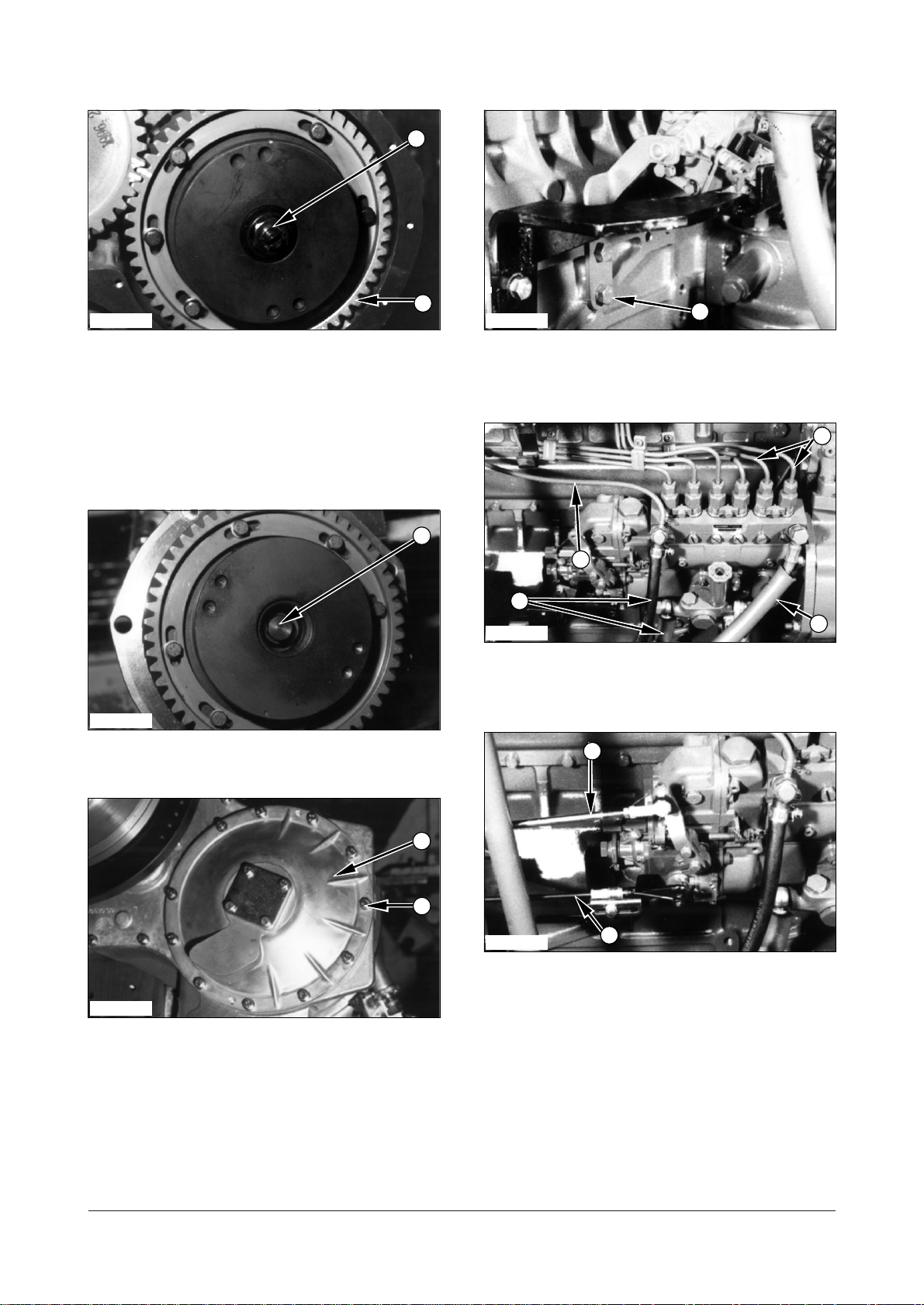
IEED116P
IEED117P
IEED114P
2
1
IEED115P
3
3
1
2
4
Page 61

3. Remove nut (5) and injection pump coupling and
gear (6) from injection pump.
4. Remove six bolts (7) and washers that hold
injection pump gear (8) in place and remove
injection pump gear (8).
5. Remove four bolts (9), washers that hold camshaft
gear in place.
6. Remove camshaft gear (10) from camshaft.
Install Timing Gears A16387-03
1. Put camshaft gear (10) in position on the camshaft
and install washers and bolts (9). Tighten bolts (9)
to a torque of 22 Nm (16 lbft).
2. Put injection pump gear (8) in position on coupling
and install washers and bolts (7).
3. Spread the end of bolts (7).
59 of 76
DE08TS Diesel Engine Disassembly and Assembly
IEED118P
IEED120P
IEED119P
Tools Needed A
Dial Indicator 1
IEED121P
5
6
7
8
9
10
IEED120P
9
7
8
10
Page 62

4. Put fuel injection pump drive coupling and gear (6)
in position. Make an alignment of the key and the
groove (slot) in the coupling.
5. Install nut (5) that hold the injection pump drive
coupling and gear (6) in place. Tighten nut (5) to a
torque of 130 Nm (96 lbft).
6. Install nut (4) into the injection pump coupling.
7. Put idler gear (3) in position on the idler gear pin,
so that the marks on the idler gear are aligned with
marks on the camshaft gear, crankshaft gear and
the injection pump gear respectively.
8. Install thrust washer (2) and bolts (1) that hold the
idler gear. Tighten the bolts to a torque of 40 Nm
(30 lbft).
9. When installing the timing gears in position, check
the amount of backlash between gears using tool
(A). If the amount of backlash is beyond the
specified value(below table) correct it.
End By :
a. Install timing gear case cover.
Timing Gear Case
Remove Timing Gear Case
A17198-02
Start By :
a. Remove timing gears
b. Remove fuel injection pump
c. Remove oil pan
1. Remove bolts (1) and then remove timing gear
case (2) from the cylinder block.
2. Remove gasket from the timing gear case.
60 of 76
DE08TS Diesel Engine Disassembly and Assembly
Backlash
Camshaft gear and idler gear 0.160.28
Crankshaft gear and idler gear 0.160.28
Injection pump drive gear and idler gear 0.160.28
IEED122P
IEED118P
5
6
IEED117P
4
1
2
IEED116P
3
1
2
Page 63

Install Timing Gear Case
A17198-03
1. Install a new gasket on the timing gear case.
2. Put timing gear case (2) in position on the cylinder
block and install bolts (1) that hold it.
End By :
a. Install oil pan.
b. Install fuel injection pump.
c. Install timing gears.
Camshaft & Camshaft
Bearing
Remove Camshaft & Camshaft
Bearing A17174 & 17078 - 02
Start By :
a. Remove rocker shaft and push rods
b. Remove timing gear cover
1. Remove four bolts (1), washers that hold camshaft
gear (2) in place.
2. Remove camshaft gear (2) from the camshaft.
3. Remove bolts (3), washers and flange (4) from the
camshaft.
61 of 76
DE08TS Diesel Engine Disassembly and Assembly
IEED124P
IEED123P
1
2
4
3
IEED122P
1
2
Page 64

4. Remove camshaft assembly (5) by carefully sliding
it out from the block. Do not force shaft as damage
can occur to the camshaft bearings.
5. Check the conditions of thrust washer (6) and
replace thrust washer (6) if needed.
6. Remove camshaft bushes (7) from the block if
necessary.
Install Camshaft And Camshaft
Bearing A17174 & A17078-03
NOTE : Make an alignment of the oil holes in the
bearing with the oil holes in the engine block.
1. Install a new bushes (7) in place in block if
removed.
2. Install thrust washer (6). Make an alignment of the
hole in the washer and the dowel in the camshaft.
62 of 76
DE08TS Diesel Engine Disassembly and Assembly
IEED126P
IEED125P
5
6
7
IEED126P
7
IEED165P
6
Page 65

3. Clean engine oil to the cams and journals of the
camshaft and the camshaft bushes, then install
camshaft (5) in position in the cylinder block.
NOTE : When installing camshaft, exercise care not
to scratch camshaft bearings.
4. Put flange (4) in place and install washers and
bolts (3) that hold the flange.
5. Put camshaft gear (2) in position on the camshaft
and install washers and bolt (1) that hold camshaft
gear (2) in the camshaft.
End By :
a. Install timing gears.
b. Install rocker shaft and push rods.
Crankshaft Pulley
Remove Crankshaft Pulley
A12660-02
Start By :
a. Remove fan belts
1. Remove eight bolts (1) and thrust washer (2) that
hold crankshaft in place. Remove crankshaft pulley
(3).
2. Remove eight bolts (4) and washers and separate
the crankshaft pulley and vibration damper (5).
63 of 76
DE08TS Diesel Engine Disassembly and Assembly
IEED127P
IEED128P
1
3
5
4
2
IEED124P
4
3
IEED123P
1
2
IEED125P
5
6
Page 66

Install Crankshaft Pulley
A12660-03
1. Put vibration damper (5) in position on the
crankshaft pulley. Install washers and bolts (4) that
hold them.
2. Put crankshaft pulley (3) in position on the
crankshaft. Install thrust washer (2) and bolts (1)
that hold crankshaft pulley. Tighten bolts (1) to a
torque of 130 Nm (96 lbft).
Flywheel
Remove Flywheel
Start By :
a. Separation of engine and transmission
1. Remove bolts (1) that hold adapter (2) in place.
2. Remove adapter (2) from the flywheel housing.
3. Remove eight bolts (3) and washers that hold
adapter and ring gear assembly (4) on the
flywheel.
4. Remove adapter and ring gear assembly (4) from
the flywheel.
64 of 76
DE08TS Diesel Engine Disassembly and Assembly
IEED129P
IEED130P
IEED127P
IEED128P
1
3
5
2
2
3
4
1
4
Page 67

5. Remove bolts (5) and washers that hold adapter
(6) on the flywheel.
6. Remove adapter (6) from the flywheel.
7. Remove two bolts (7) and washers that hold
bushing on adapter (6).
8. Replace bushing (8) with new one if they was
worn or damaged.
9. Remove two bolts opposite each other and install
two M14x1.5 guide bolts in the flywheel.
10. Remove the remainder of bolts (9) and then
remove flywheel (10).
11. Remove flywheel ring gear (11) with a brass
punch. If necessary, put a little heat on the
flywheel ring gear.
Install Flywheel A13366-03
1. Heat ring gear (11) to a maximum temperature of
246(475). Install the ring gear so the chamfer
on the gear teeth is next to the starter pinion when
the flywheel is installed.
65 of 76
DE08TS Diesel Engine Disassembly and Assembly
IEED131P
11
IEED132P
IEED133P
Tools Needed A
Dial Indicator Group 1
IEED007S
5
686109
7
11
IEED007S
Page 68

2. Install two M14x1.5 guide bolts in opposite holes of
the crankshaft flange.
3. Install enough bolts (9) with Loctite No.271 to hold
flywheel (10) in position. Remove guide bolts.
4. Install remainder of bolts (9). Tighten bolts (9) to a
torque of 180 Nm (133 lbft).
Typical Example
5. Check the flywheel face runout as follows:
a. Install tool group (A) as shown. Move the
crankshaft the same way before the indicator is
read so the crankshaft end clearance
(movement) is always removed.
b. Set the dial indicator to read 0.0 mm (.000 in.).
c. Turn the flywheel and read the indicator every 90
d. The difference between the lower and higher
measurements taken at all four points must not
be more than 0.20mm (.008in.) which is the
maximum permissible face runout (axial
eccentricity) of the flywheel.
Typical Example
6. Check the pilot bore runout of the flywheel as follows:
a. Install tool group (A) as shown.
b. Set the dial indicator to read 0.0 mm (.000 in.).
c. Turn the flywheel and read the indicator at 90
intervals.
d. The difference between the lower and higher
measurements taken at all four points must not be
more than 0.30 mm (.0.12 in.) which is the maximum
pilot bore runout (eccentricity) of the flywheel.
Typical Example
7. Check the outside diameter runout of the flywheel
as follows:
a. Install tool group (A) at top dead center of the
flywheel as shown. Mount the dial indicator to
the flywheel housing or the engine block.
b. Set the dial indicator to read 0.0 mm (.000 in.).
c. Turn the flywheel and read the indicator every 90
d. The difference between the lower and higher
measurements taken at all four points must not
be more than 0.30 mm (.012 in.) which is the
maximum permissible outside diameter runout
(eccentricity) of the flywheel.
66 of 76
DE08TS Diesel Engine Disassembly and Assembly
IEED134P
IEED135P
IEED136P
IEED133P
10
AAA
9
Page 69

8. Install bushing (8) in position on adapter (6) and
tighten bolts (7) to a torque of 124 Nm (106
35 lbin).
9. Put the anti-seize compound (FEL-PRO C5-A)
inside of bushing (8).
10. Put adapter (6) in position and install bolts (5) and
washers that hold adapter (6) on the flywheel.
Tighten bolts (5) to a torque of 5510 Nm (40
7 lbft).
11. Put the adapter and ring gear assembly (4) in
position and install bolts (3) and washers that
hold adapter and ring gear assembly (4) on the
flywheel. Tighten bolts (3) to a torque of
5510 Nm (407 lbft).
12. Put adapter (2) in position and install bolts (1) that
hold adapter (2) on the flywheel housing. Tighten
bolts (1) to a torque of 55 10 Nm (40 7 lbft).
End By :
a. Connection engine and transmission.
67 of 76
DE08TS Diesel Engine Disassembly and Assembly
IEED131P
5
6
IEED130P
3
4
IEED132P
8
6
7
IEED129P
2
1
Page 70

Flywheel Housing
Remove Flywheel Housing
A11453-02
Start By :
a. Remove flywheel
b. Remove electric starting motor
1. Fasten tool (A) and a hoist to the flywheel housing.
Remove bolts (2) to remove housing (1)
NOTE : Flywheel housing is put in a location with
dowels.
2. Remove lip type seal (3) from flywheel housing (1)
and discard it.
Install Flywheel Housing
A11453-03
1. Install lip type seal (3) in flywheel housing (1) using
tool (B).
2. Fasten tool (A) and a hoist to the flywheel housing.
3. Put flywheel housing (1) in position on the dowels.
Install bolts (2) that hold it in position. Tighten bolts
(2) to a torque of 80 Nm (60 lbft).
Tools Needed A B
Link Bracket 1
Seal Installer 1
68 of 76
DE08TS Diesel Engine Disassembly and Assembly
Tools Needed A
Link Bracket 1
IEED137P
IEED008S
1
2
IEED137P
1
2
1
3
IEED008S
1
3
Page 71

Crankshaft
Remove Crankshaft A12264-02
Start By :
a. Remove oil pump
b. Remove timing gear case
c. Remove flywheel housing
NOTE : Put identification on the main bearings and
the thrust washers for correct installation if used
again.
1. Remove bolts (1). Remove crankshaft main
bearing caps (2). Remove the lower main bearing
halves from the caps and the thrust washers from
the outer main cap.
2. Remove bolts (3). Remove connecting rod caps
(4).
3. Fasten straps and a hoist to the crankshaft
4. Remove crankshaft (5).
Typical Example
5. Remove upper main bearing halves (6).
6. Remove thrust washers (7) from the center main.
7. Remove gear (8) from the crankshaft with tool (A).
Remove the dowel.
69 of 76
DE08TS Diesel Engine Disassembly and Assembly
Tools Needed A
Spuller Assembly
Ratchet Box Wrench
Bearing Puller Attachment
Step Plate
IEED139P
IEED140P
IEED141P
5
IEED138P
2
1
3
4
8
7
6
Page 72

Install Crankshaft A12264-03
1. Check all parts for damage. If damaged, use new
parts for replacement.
2. Make sure all parts are clean and free of dirt and
foreign material.
3. Install dowel and gear (8) on the crankshaft.
Typical Example
NOTE : Put clean engine oil on the crankshaft main
jounals, the main bearings and thrust washers. The
upper main bearing halves have a long oil groove
(slot). If the same bearings and thrust washers are
used again, install as per identification.
4. Put upper main bearing halves (4) in position. The
tabs on the bearings must be in alignment with the
notches in the housing. Install the thrust washers
in the center main housing. The steel side of the
thrust washers must be next to or toward the
engine block and the cap.
5. Fasten two straps and a hoist to crankshaft(5). Put
the crankshaft in position. Remove the hoist and
the straps.
Typical Exqmple
6. Install lower main bearing halves (2) in the caps.
The tabs on the bearings must be in alignment with
the notches in the caps. Install the thrust washers
in the center main cap.
NOTE : The tabs of the lower main bearing halves
must be on the same side as the tabs on the upper
main bearing halves.
7. Install all bolt one of the main bearing caps as per
identification.
NOTE : Do not turn the crankshaft as it will damage
the plastigage.
8. Put the plastigage in position on the lower main
bearing half.
70 of 76
DE08TS Diesel Engine Disassembly and Assembly
IEED142P
IEED143P
IEED141P
8
IEED139P
5
2
4
Page 73

9. Put the bearing cap in position and tighten the
bolts to a torque of 300 Nm (220 lbft).
10. Remove the main bearing cap and measure the
Plastigage. The bearing clearance for new
bearings must be 0.025 to 0.075 mm (.001 to
.003 in.).
11. Put clean engine oil on the bearing and the
crankshaft journal.
12. Install main bearing cap (2). Tighten the bolts to a
torque of 300 Nm (220 lbft).
13. Do Steps 8 through 12 for the other main
bearings.
Typical Example
14. Measure the crankshaft end play. The end play
must be 0.15 to 0.325 mm (.006 to .013 in.).
15. Put clean engine oil on the connecting rod bolt
threads. Install all bolt one of the connecting rod
caps.
16. Use Plastigage to check the bearing clearance of
the connecting rods. Install connecting rod cap
(7) and tighten the to a torque of 180 Nm (133
lbft).
17. Remove the connecting rod cap and measure the
Plastigage. The bearing clearance for new rod
bearing must be 0.025 to 0.075 mm (.001 to .003
in.).
18. Put the connecting rod cap in position and install
the nuts. Tighten the nuts to a torque of 180 Nm
(133 lbft).
19. Do steps 16 through 18 for the other connecting
rod caps.
End By :
a. Install flywheel housing.
b. Install timing gear case.
c. Install oil pump.
71 of 73
IEED144P
IEED138P
2
1
3
4
7
Page 74

Air Compressor (if equipped)
Remove Air Compressor
1. Loosen the tension adjusting bolts and nut (1) and
nut attached on the idle pulley.
2. Take off V-belts (2).
3. Disconnect tube (3) from the air compressor.
4. Loosen clamp and disconnect hose (4).
5. Remove four bolts (5) and washers that hold the
air compressor assembly in place. Remove air
compressor assembly (6).
6. Remove nut (7), washer and pulley (8) from air
compressor.
Install Air Compressor
1. Put air compressor assembly (6) in position on the
idle gear bracket.
2. Install bolts (5) and washers that hold it.
Tighten bolts (5) to a torque of 22 Nm (16 lbft).
3. Connect oil supply tube (3) and air supply hose (4)
on the air compressor.Tighten the hose clamp.
72 of 76
DE08TS Diesel Engine Disassembly and Assembly
IEED145P
IEED147P
IEED146P
IEED146P
IEED009S
2
6
345
IEED147P
6
513
4
8
7
Page 75

4. Assemble V-bolts (2) and adjust the tension of V-
belt using tension adjusting bolt (1). Tighten
tension adjusting bolts (1).
Disassemble Air Compressor
Start By :
a. Remove air compressor
1. Remove plug (1) and drain oil from the crankcase.
NOTE : For the purpose of reassembly, put Loctite
No.572 on plug (1).
2. Remove four bolts (2) and washers that hold the
cylinder head on the cylinder.
NOTE : For the purpose of reassembly, tighten bolts
(2) to a torque of 2531 Nm (1923 lbft).
3. Remove cylinder head (3).
4. Remove gasket (4) and discard it.
5. Remove seat plate assembly (5) from the cylinder.
6. Remove two bolts (6), washers, pressure catcher
(7) and disc if needed.
73 of 76
DE08TS Diesel Engine Disassembly and Assembly
Tools Needed A
Bearing Puller 1
IEED148P
IEED149P
IEED150P
IEED151P
1
576
4
IEED145P
2
2
3
1
Page 76

7. Remove suction disc (8).
8. Remove gasket (9) and discard it.
9. Remove four nuts (10) and washers that hold
cylinder (11) on the crankcase.
NOTE : For the purpose of reassembly, tighten nuts
(10) to a torque of 1721 Nm (150186 lbft).
10. Remove cylinder (11) from the crankcase.
11. Remove gasket and discard it.
12. Remove two bolts (12) and separate piston and
connecting rod assembly (13) from the
crankshaft.
NOTE : For the purpose of reassembly, tighten bolts
(12) to a torque of 2732 Nm (2024 lbft)
NOTE : Put identification on all parts for correct
assembly.
13. Remove three oil rings (14) and wiping ring (15)
using a piston ring expander.
14. Remove piston pin (16) and snap rings from both
side of the piston using snap ring plier.
15. Remove piston pin (16) and connecting rod (17)
from piston (18).
16. Inspect bushings (19) and (20) in connecting rod
(17). If the bushings has a large amount of wear,
make a replacement of the bushing.
74 of 76
DE08TS Diesel Engine Disassembly and Assembly
IEED152P
IEED153P
IEED154P
IEED155P
IEED156P
IEED157P
8
9
15
14
16
17
18
11
10
13
20
19
17
12
Page 77

17. Remove four bolts (21) and washers that hold
bearing cover (22) on the crankcase.
NOTE : For the purpose of reassembly, put Loctite
No.572 on bolt thread and tighten bolts (21) to a
torque of 1721 Nm (150186 lbft).
18. Remove four bolts (23), washers and end cover
(24) from the crankcase.
19. Remove gasket and discard it.
20. From rear of crankcase tap crankshaft from
crankcase (33).
21. Remove the crankshaft assembly and bearing
cover (25) as a unit.
22. Remove O-ring (26) from the bearing cover.
23. Remove woodroof key (27) from the crankshaft.
24. Remove bearing cover (28) using tool (A).
25. Remove oil seal (29) from bearing cover (28).
26. Remove bearing (30) from crankshaft (31).
75 of 76
DE08TS Diesel Engine Disassembly and Assembly
IEED158P
IEED159P
IEED160P
IEED161P
IEED162P
IEED163P
23
28
27
29
283130
24
22
21
33
25
26
Page 78

27. Inspect bushing (32) in the crankcase (33). If the
bushing has a large amount wear, replace with
new one.
28. Assemble the air compressor assembly in
reverse order of disassembly.
End By :
a. Install air compressor.
76 of 76
DE08TS Diesel Engine Disassembly and Assembly
IEED164P
32
33
 Loading...