

DoorKing 9000 Quick Start Manual
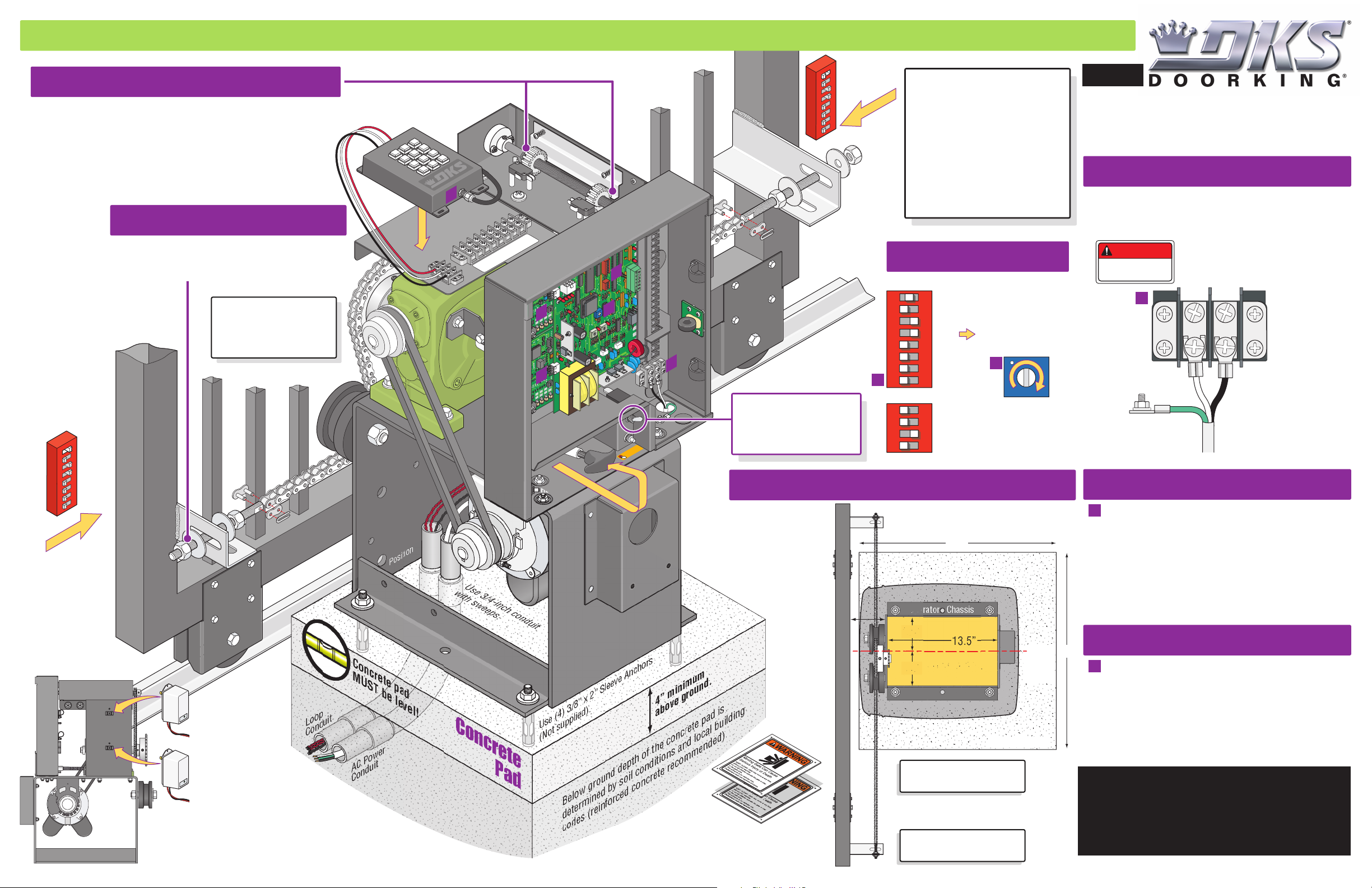
QUICKSTART “BASIC” GUIDELINES FOR MODEL 9000 - FRONT INSTALLATION MOUNTED ON A CONCRETE PAD “FULL OPEN”
Adjustment of Limit Switches
Adjust the 2 limit nuts by depressing the lock plate and spin nuts to
desired open and closed gate positions. After adjusting, make sure
the lock-plate is engaged in the slots on the limit-nuts to prevent
them from rotating. See manual for more information.
Chain Adjustment
Adjust the chain nuts to tighten the chain. The chain
should sag no more than one (1) inch per 10 feet of
chain travel. Do not over tighten the chain.
Chain brackets MUST be
mounted so the chain
remains the same height
as it is on the idler wheels!
ON
1 2345678
Switch 1
in ON
position.
SW 1
Opening
Direction
Loop
Conduit
Radio Receiver
Idler
Wheel
Idler Wheel
Top Position
Concrete pad
MUST be level!
1
3-Wire
Center
Position
Bottom
Position
ON
1 2 3 4 5 6 7 8
Switch 1
in OFF
position.
3
6
2
9
5
#
8
4
0
7
*
Lock Plate
Chain Bracket
SW 1
Opening
Direction
Model 9000 is intended for
installation only on sliding
gates used for vehicles.
Pedestrians must be supplied with
a separate access opening.
For complete safety, installation
and adjustment of operator
instructions, please refer to the
C
Series 9000 Installation/Owner’s
manual.
UL 325 August
2018 Standard
120 S. Glasgow Avenue
Inglewood, California 90301
U.S.A.
High Voltage Connection
GATE OPERATOR MUST BE PROPERLY GROUNDED!!
Tip: It is recommended that a surge suppressor be
8
COM
7
Limit
6
Spare
5
Limit
4
24VAC
3
Neutral
2
Motor
1
Motor
D
B
E
A
B
Reset
Manual Release
Power
PUSH TO OPERAT
technician use only
DO NOT
operator until the “DIP-Switches”
and the “Limit Switches” have
E
been adjusted. Damage could
occur to the gate and operator.
power up and cycle the
Chain, Conduit Area and Concrete
D
DIP-Switches
Typical Single Operator Settings
ON
1
2 3 4 5 6 7 8 1
SW 1
2 3 4
SW 2
1. Opening Direction
2. OFF
3. ON
Auto-Close Timer
(See reverse side for
more information).
ON
4. ON
5. OFF
6. OFF
7. OFF
8. OFF
1. OFF
2. OFF
3. ON
4. OFF
E
1 to 23 sec.
(See Illustration)
TIME
DELAY
123
Adjust
installed on the input high voltage power line.
DANGER
HIGH VOLTAGE
A
115 VAC
Neutral
Hot
Note: “Optional” High
Voltage Kit black and
white wires connect
the same as shown.
See High Voltage Kit
instruction sheet for
more information.
Input Power Line:
Chassis
Ground
White - Neutral
Black - 115 VAC Hot
Green - Chassis Ground
Loop Detectors
Not included - Refer to the Installation/Owner’s manual
B
for more information about DoorKing’s Plug-In loop
24”
detectors. DoorKing highly recommends that loops and
loop detectors are installed with this slide gate operator.
DoorKing offers a free “Loop and Loop-Detectors
Use 3/4-inch conduit
with sweeps.
Concrete
4” minimum
above ground.
Use (4) 3/8” x 2” Sleeve Anchors
(Not supplied).
4” minimum
space
between the
gate and
operator
chassis.
Gate
4”
Operator Chassis
3.5”
4.5”
13.5”
Conduit Area
Center
of
concrete
pad
Concrete Pad
24”
Information Manual” PDF located at DoorKing’s web
site for more information. www.doorking.com
Radio Receiver
Not included - Refer to a specific Radio Receiver
C
Manual (available from www.doorking.com) for more
information on radio receivers and antenna installation.
(See reverse side for wiring)
Two 115 VAC
Convenience Outlets
For access control and safety device AC power.
AC Power
Conduit
Pad
Below ground depth of the concrete pad is
determined by soil conditions and local building
codes (reinforced concrete recommended).
Copyright 2019 DoorKing®, Inc. All rights reserved.
Warning Signs
Permanently mount signs on BOTH sides of the
gate area and make sure they are easily visible.
Operator and chain
MUST be parallel to gate!
Chain bracket MUST line
up with chain idler wheels!
Entrapment Protection must be provided for the gate
system where the risk of entrapment or obstruction exists.
The operator will NOT run without one or more monitored
type B1 or B2 external entrapment protection devices in
EACH direction of gate travel (minimum of 2 external
devices required). See manual for more information.
9000-066-K-2-19
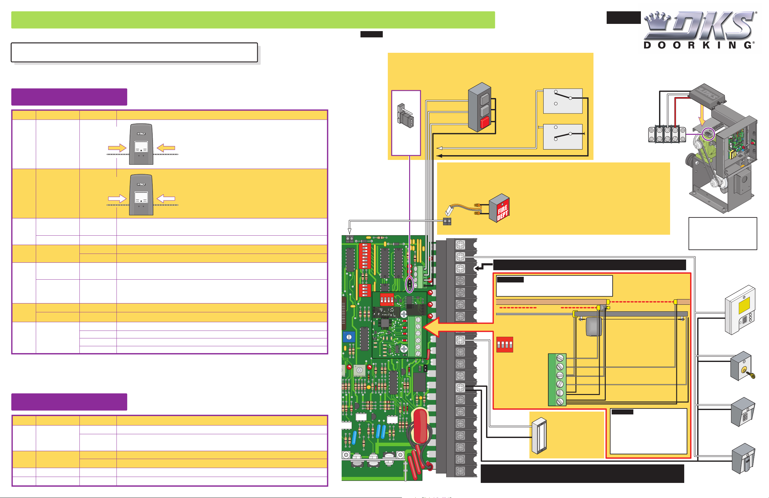
QUICKSTART “BASIC” GUIDELINES FOR MODEL 9000 - DIP-SWITCH AND WIRING REFERENCE
Important: Controls intended for user activation must be located at least six (6) feet away from any moving part of the gate and where
the user is prevented from reaching over, under, around or through the gate to operate the controls. Emergency access controls only
Model 9000 is intended for installation only on slide gates used for vehicles.
Pedestrians must be supplied with a separate access opening.
For safety and installation instructions, please refer to the Installation/Owner’s manual.
SW 1 DIP-Switches
Switch Function Setting Description
1
2
3
4
5
6
7 and 8
Primary
Operator
Opening
Direction
Secondary
Operator
Opening
Direction
Exit Loop Port
Output
Full Open Input
Auto-Close
Timer
Reverses Gate
Stops Gate
Single Operator
Dual Operators
Relay
Opening direction
using ON setting.
Opening direction
using ON setting.
The output wired to terminal #4 becomes the output from the exit loop detector
OFF
plugged into the EXIT Loop port.
Normal Setting. Terminal #4 is a normal full open input.
ON
Auto-close timer is OFF. Manual input required to close gate.
OFF
Normal Setting. Auto-close timer is ON. Adjustable from 1-23 seconds.
ON
Normal Setting. Input to terminal #6 and reverse loop will reverse gate during
OFF
close cycle.
Input to terminal #6 and/or reverse loop will stop gate during close cycle – gate will
ON
continue to close after input to terminal #6 and/or reverse loop are cleared (Helps
prevent tailgating).
Normal Setting. Switch must be OFF for single operator.
OFF
Switch must be ON when primary/secondary (dual) gates are used.
ON
7-OFF
7-OFF
7-ON
7-ON
8-OFF
8-OFF
Normal Setting. Relay activates when gate is at open limit.
Relay activates when gate is not closed.
8-ON
Relay activates when gate is opening and open.
Relay activates during opening and closing cycle.
8-ON
Opening direction
using OFF setting.
Changes direction operator will cycle open
upon initial AC power up and open command.
Opening direction
using OFF setting.
Changes direction operator will cycle open
upon initial AC power up and open command.
Note: After a DIP-switch setting is changed, power must be turned
OFF and then turned back on for the new setting to take affect.
SW 2 DIP-Switches
Switch Function Setting Description
Normal Setting. Timer will function normally.
1
2
3
4
Quick-Close
Timer Override
Magnetic lock
OFF
Opening gate will stop and begin to close as soon as all reversing inputs (Reverse
ON
loops, photo sensors) are cleared regardless of the distance the gate has opened.
Normal Setting. Magnetic lock is not used.
OFF
Magnetic lock is used and connected to terminals 9 and 12.
ON
Normal Setting. Switch 3 MUST be turned ON for Model 9000 operator.
ON
Normal Setting. Switch 4 MUST be turned OFF for Model 9000 operator.
OFF
P2
EXIT
LOOP
REVERSE
LOOP
POWER
REV SENSE
SECONDARY
accessible by authorized personnel (e.g., fire, police, EMS) may be placed at any location in the line-of-sight of the gate.
4-Pin Non-Removable Terminal
3-Button Control Station
Use a standard 4-wire 3-button control station. DoorKing’s
3-wire 3-button control station cannot be used.
3-Pin With
Jumper
Place jumper
on bottom
2 pins when
using 4-pin
terminal.
#1 Open N.O.
#2 Close N.O.
#3 Stop N.C.
#4 Com
Fire Dept Open
Supplied
Wire Harness
1
2
3
4
5
6
7
8
9
10
11
FIRE
TIME
DELAY
2 3 4 5 6 7 8
1
2 3 41
REV SENSE
PRIMARY
ON SW1
ON SW2
ON
SW1
1
UL 325
DIP switches
2 3 4
1
2
3
4
1477-010
UL 325
Terminal
1
2
3
4
5
6
NC
FIRE
Com
Full
Open
2
24
VAC
4
5
6
OB
7
CB
8
OE
CE
24
VDC
G
G
NO
12
Com
13
14
15
16
17
18
19
4405-018
20
20
UL 325 August
2018 Standard
Normally Closed
Interlock Switch
Operator Cycling
Note: When
using 3-button
OPEN
control station
AND interlock
CLOSE
switch together,
STOP
#3 terminal
(N.C.) must be
wired in series.
To #3 Stop N.C.
To #4 Com
Gate will ONLY OPEN when this device is activated by authorized personnel ONLY (fire,
police, EMS) and operator has power. Alarm will sound during entire open cycle.
Operator will then go into a hard shutdown once fully opened. Operator MUST be reset to
function normally again. This device MUST be mounted in the line-of-site of gate so
authorized personnel can monitor gate movement.
Dual Gate Operators Note: Connect device to BOTH operators, both gates will fully open.
Activation Note: Activation of this device will OPEN gate regardless of the status of the
open direction monitored external entrapment protection device(s). If gate is opening,
and the operator’s inherent entrapment protection system detects an obstruction, the
operator will reverse approx. 2 inches and go into a hard shutdown. Operator reset
button MUST be pushed to function again OR cycle operator’s power.
Terminal #3 Note: Exceeding 250 mA of power from this terminal may cause the circuit board transformer to overheat,
causing intermittent problems.
IMPORTANT: Only 1 monitored Device can be connected
to each input. An OPTIONAL Expansion Kit (sold
separately) will allow connection for additional devices.
Open Beam necessary when area between
gate and wall is between 2 1/4” and 16”.
N.C.
Com
N.O.
Lock Engaged
Operator Stopped
N.C.
N.O.
Lock Disengaged
Wall
Com
Filler Post If necessary
3-Pin
Remote
Terminal
Power is limited
to 250 mamps.
External Entrapment
Protection Devices
Close Beam
Open EdgeOpen Beam
Closed Gate
Com
Relay
123
24 Volt
UL 325 DIP-Switches
DIP-switches MUST be turned ON
for each device wired to terminal.
1ON2 3 4
CLOSE Beam REVERSE
OPEN Edge/Beam REVERSE
CLOSE Edge/Beam REVERSE
#9 Normally
Close
24 Volt 1 amp max.
UL 325 Terminal
OPEN Beam STOP
UL 325 switch 1
UL 325 switch 2
UL 325 switch 3
UL 325 switch 4
(Common) Ground
(Common) Ground
1
2
3
4
5
6
Magnetic Lock
Power (24-Volt DC) and
logic output. Power is shut
off .5 sec. prior to gate
starting and remains off
while gate is opening and
in the open position.
Entrapment Protection must be provided for the gate system where the risk of entrapment or obstruction exists.
The operator will NOT run without one or more monitored type B1 or B2 external entrapment protection devices
in EACH direction of gate travel (minimum of 2 external devices required).
Open Edge
N.C.
N.C.
N.C.
N.C.
N.C.
Connect ONLY MONITORED
Devices
IMPORTANT: Photo sensors must use
Normally Closed (NC) contacts with the beam
set for light operate (relay activated when
beam is not obstructed). Some manufacturer’s
photo sensor contacts are labeled as Normally
Open (NO) but their relay functions the same
way as described above. See specific
manufacturer’s wiring manual for more
information about their specific relay function.
120 S. Glasgow Avenue
Inglewood, California 90301
3-Wire Radio
Receiver
8
M
O
C
7
Limit
6
e
par
S
5
Limit
4
24VAC
3
tral
Neu
2
Motor
1
Motor
Type of wiring to be used on ALL
external devices:
A) Type CL2, CL2P, CL2R, or CL2X.
B) Other cable with equivalent or better
electrical, mechanical, and flammability
ratings.
#2 Normally Open
Telephone
Entry
Close Edge
Stand-Alone
Key Switch
Stand-Alone
Keypad
Stand-Alone
Card Reader
Note: All stand-alone
and telephone entry devices must
use a separate power source.
Power
OPERA
u
O
T
an
i
nic
h
c
PUSH
te
U.S.A.
E
T
y
l
n
o
e
s
 Loading...