


 Loading...
User’s Manual
Version 6.3C
Account Manager Software for Windows
DoorKing, Inc. 120 Glasgow Avenue Inglewood, California 90301
U.S.A.
Phone: 310-645-0023 Fax: 310-641-1586
www.doorking.com
P/N 1835-066 REV N, 7/13
Copyright 2013 DoorKing, Inc. All rights reserved.
Page 2 |
1835-066-N-7-13 |
NOTICE
DOORKING INC. reserves the right to make changes in the product described in this manual at any time and without notice or obligation of DoorKing Inc. to notify any persons of any such revisions or changes. Additionally, DoorKing Inc. makes no representations or warranties with respect to this manual. This manual is copyrighted, all rights reserved. No portion of this manual may be copied, reproduced, translated, or reduced to any electronic medium without prior written consent from DoorKing Inc.
Companies, apartment complexes, names, and data used in the examples in this manual are fictitious unless otherwise noted.
END-USER LICENSE AGREEMENT FOR DOORKING SOFTWARE
IMPORTANT – READ CAREFULLY: This DoorKing End-User License Agreement (EULA) is a legal agreement between you (either an individual or entity) and DoorKing, Inc. for DoorKing software products which includes computer software programs and may include associated media, printed materials or other electronic documentation (SOFTWARE PRODUCT). By installing, copying, or otherwise using the SOFTWARE PRODUCT, you agree to be bound by the terms of this EULA. If you do not agree to the terms of this EULA, do not install or use the SOFTWARE PRODUCT.
SOFTWARE PRODUCT LICENSE
The SOFTWARE PRODUCT is protected by copyright laws and international copyright treaties, as well as other intellectual property laws and treaties. The SOFTWARE PRODUCT is licensed, not sold.
DOORKING, Inc. licenses the DoorKing SOFTWARE PRODUCT for your use only. You assume all responsibility for the installation, operation and results. You may create copies of the SOFTWARE PROGRAM. You may not copy the printed materials or other electronic documentation accompanying the SOFTWARE PRODUCT.
You may not reverse engineer, disassemble or decompile the SOFTWARE PRODUCT nor copy its features or methods of operation for use in any other program. You recognize that DoorKing’s source code, data, features and methods of operation are trade secrets belonging to DoorKing.
You may permanently transfer all of your rights under this EULA, provided you retain no copies, you transfer all of the SOFTWARE PRODUCT (including the media and printed materials) and the recipient agrees to the terms of this EULA.
Without prejudice to any other rights, DoorKing may terminate this EULA if you fail to comply with the terms and conditions of this EULA. In such event, you must destroy all copies of the SOFTWARE PRODUCT and all of its component parts.
LIMITED WARRANTY
DOORKING, INC. warrants that the SOFTWARE PRODUCT will perform substantially in accordance with the accompanying written materials for a period of ninety (90) days from the date of receipt.
DOORKING, INC. warrants the diskettes on which on which the software is recorded to be free from defects in materials and faulty workmanship under normal use for a period of ninety (90) days after the date of the original purchase. If during this 90 day period a defect in the diskette should occur, the diskette may be returned for replacement without charge through your authorized DoorKing dealer. Your sole remedy in the event of a defect in a diskette is limited to replacement of the diskette as provided above. This remedy is your exclusive remedy for breach of this warranty. It gives you certain rights and you may have other rights which vary from state to state.
EXCEPT FOR THE EXPRESS WARRANTY ABOVE, THE DOORKING REMOTE ACCOUNT MANAGER (PRODUCT) IS PROVIDED ON AN "AS IS" BASIS, WITHOUT ANY OTHER WARRANTIES, OR CONDITIONS, EXPRESS OR IMPLIED, INCLUDING BUT NOT LIMITED TO WARRANTIES OF MERCHANTABLE QUALITY, MERCHANTABILITY OR FITNESS FOR A PARTICULAR PURPOSE, OR THOSE ARISING BY LAW, STATUTE, USAGE OF TRADE OR COURSE OF DEALING. THE ENTIRE RISK AS TO THE RESULTS AND PERFORMANCE OF THE PRODUCT IS ASSUMED BY YOU. NEITHER WE NOR OUR DEALERS OR DISTRIBUTORS SHALL HAVE ANY LIABILITY TO YOU OR ANY OTHER PERSON OR ENTITY FOR ANY INDIRECT, INCIDENTAL, SPECIAL OR CONSEQUENTIAL DAMAGES WHATSOEVER, INCLUDING BUT NOT LIMITED TO LOSS OF REVENUE OR PROFIT, LOST OR DAMAGED DATA OR OTHER COMMERCIAL OR ECONOMIC LOSS, EVEN IF WE HAVE BEEN ADVISED OF THE POSSIBILITY OF SUCH DAMAGES OR THEY ARE FORESEEABLE; OR FOR CLAIMS BY A THIRD PARTY. OUR MAXIMUM AGGREGATE LIABILITY TO YOU, AND THAT OF OUR DEALERS AND DISTRIBUTORS SHALL NOT EXCEED THE AMOUNT PAID BY YOU FOR THE PRODUCT. THE LIMITATIONS IN THIS SECTION SHALL APPLY WHETHER OR NOT THE ALLEGED BREACH OR DEFAULT IS A BREACH OF A FUNDAMENTAL CONDITION OR TERM, OR A FUNDAMENTAL BREACH. SOME STATES / COUNTRIES DO NOT ALLOW THE EXCLUSION OR LIMITATION OF LIABILITY FOR CONSEQUENTIAL OR INCIDENTAL DAMAGES SO THE ABOVE LIMITATIONS MAY NOT APPLY TO YOU.
1835-066-N-7-13 |
Page 3 |

TABLE OF CONTENTS
Section 1 – Introduction
1.1 |
Installation Guidelines – All Systems........................................................................................................ |
7 |
1.2Getting Started
|
1.2.1 |
Windows 8, Windows 7, Windows Vista or Windows XP Install |
..............................................8 |
|
1.2.2 |
File Information......................................................................................................................... |
9 |
|
1.2.3 |
Security Levels ......................................................................................................................... |
10 |
|
1.2.4 |
Elevator Control........................................................................................................................ |
10 |
|
1.2.5 |
Hold Open Time Zones ............................................................................................................ |
10 |
|
1.2.6 |
Holiday Schedule ..................................................................................................................... |
11 |
|
1.2.7 |
Transactions............................................................................................................................. |
11 |
|
1.2.8 |
Live Transactions ..................................................................................................................... |
11 |
|
1.2.9 |
Live Streaming ......................................................................................................................... |
11 |
|
1.2.10 |
Anti-Pass Back ......................................................................................................................... |
11 |
|
1.2.11 |
Users ........................................................................................................................................ |
11 |
|
1.2.12 |
Port Configuration .................................................................................................................... |
11 |
|
1.2.13 |
Clock Setting ............................................................................................................................ |
12 |
|
1.2.14 |
Prior to Programming ............................................................................................................... |
12 |
|
1.2.15 |
Start the Program ..................................................................................................................... |
12 |
|
1.2.16 |
Series Column.......................................................................................................................... |
12 |
Section 2 – Account Management |
|
||
2.1 |
Account Information.................................................................................................................................. |
13 |
|
|
2.1.1 |
Creating User Types ................................................................................................................ |
14 |
|
2.1.2 |
Creating a New Account........................................................................................................... |
15 |
|
2.1.3 |
Editing Account Information ..................................................................................................... |
16 |
|
2.1.4 |
Deleting Accounts .................................................................................................................... |
16 |
2.2 |
Share Information Feature........................................................................................................................ |
17 |
|
2.3Communication Port Configuration
|
2.3.1 |
Communication Configuration .................................................................................................. |
18 |
|
2.3.2 |
Server Login / Registration....................................................................................................... |
18 |
Section 3 – System Management |
|
||
3.1 |
Entry Panel Programming ........................................................................................................................ |
19 |
|
|
3.1.1 |
Entry Panel Setup .................................................................................................................... |
20 |
|
3.1.2 |
Communication Setup .............................................................................................................. |
20 |
|
3.1.3 |
Tone Open Numbers................................................................................................................ |
20 |
|
3.1.4 |
Entry Codes.............................................................................................................................. |
21 |
|
3.1.5 |
Miscellaneous Setup Items ...................................................................................................... |
22 |
|
3.1.6 |
System Message...................................................................................................................... |
22 |
3.2 |
Relay Numbering and Control .................................................................................................................. |
23 |
|
|
3.2.1 |
Labeling Relays with Tracker Disabled .................................................................................... |
24 |
|
3.2.2 |
Labeling Relays with Tracker Enabled ..................................................................................... |
25 |
3.3Relay Hold Open Time Zone Programming
|
3.3.1 |
Creating Relay Hold Time Zones ............................................................................................. |
26 |
|
3.3.2 |
Applying Relay Hold Time Zones ............................................................................................. |
27 |
3.4 |
Holiday Schedule...................................................................................................................................... |
28 |
|
3.5 |
Security Levels ......................................................................................................................................... |
29 |
|
|
3.5.1 |
Planning Security Levels .......................................................................................................... |
30 |
|
3.5.2 |
Creating Security Levels .......................................................................................................... |
31 |
3.6Anti-Pass Back (APB)
3.6.1 |
True Anti-Pass Back |
.................................................................................................................33 |
3.6.2 |
Facility Counter ........................................................................................................................ |
33 |
Page 4 |
|
1835 - 066 - N-7-13 |
3.6.3 |
Re-Sync Operations................................................................................................................. |
33 |
3.6.4 |
Programming Anti-Pass Back .................................................................................................. |
34 |
3.7Facility Codes and Device Association
3.7.1 |
Facility Codes........................................................................................................................... |
35 |
3.7.2 |
Device Association................................................................................................................... |
36 |
3.7.3 |
Mass Enable ............................................................................................................................ |
37 |
3.8Elevator Control
|
3.8.1 |
Planning Elevator Control / Security Levels ............................................................................. |
38 |
|
3.8.2 |
Programming the Relay / Elevator Control Table..................................................................... |
39 |
|
3.8.3 |
Programming Security Levels with Elevator Control ................................................................ |
40 |
Section 4 – Database Management |
|
||
4.1 |
User (Resident) Information ..................................................................................................................... |
45 |
|
|
4.1.1 |
Adding Resident (User) Information......................................................................................... |
46 |
4.2 |
Assigning Device Codes .......................................................................................................................... |
48 |
|
4.3Elevator Reference
4.3.1 |
Programming the Elevator Reference Table............................................................................ |
49 |
4.3.2 |
Assigning Elevator Reference to Residents............................................................................. |
50 |
Section 5 – Data Transfer / Reports
5.1Transfer Now
5.1.1 |
Send Data Now ........................................................................................................................ |
52 |
5.1.2 |
Receiving Data Now................................................................................................................. |
53 |
5.1.3 |
Receiving Transactions............................................................................................................ |
54 |
5.2Scheduled Transfers
5.2.1 |
Scheduling Transfers ............................................................................................................... |
55 |
5.3Viewing / Reporting Transactions
|
5.3.1 |
Viewing Transactions and Reports .......................................................................................... |
56 |
|
5.3.2 |
Viewing Live Transactions ....................................................................................................... |
58 |
|
5.3.3 |
Creating Transaction Reports .................................................................................................. |
59 |
|
5.3.4 |
Exporting Reports .................................................................................................................... |
59 |
5.4 |
Live Streaming.......................................................................................................................................... |
60 |
|
|
5.4.1 |
Output Destinations.................................................................................................................. |
60 |
|
5.4.2 |
Output Format .......................................................................................................................... |
61 |
5.5 |
Log Files |
................................................................................................................................................... |
62 |
5.6Exporting / Importing Database Files
5.6.1 |
Exporting Data ......................................................................................................................... |
63 |
5.6.2 |
Importing Data in CSV Format (Microsoft Excel) ..................................................................... |
64 |
5.6.3 |
Main Frame Import................................................................................................................... |
66 |
Section 6 – Appendix
6.1Backup and Restore
6.1.1 |
Backup ..................................................................................................................................... |
69 |
6.1.2 |
Restore..................................................................................................................................... |
69 |
6.2Trouble Shooting
|
6.2.1 |
Modem ..................................................................................................................................... |
70 |
|
6.2.2 |
Entry System ............................................................................................................................ |
70 |
|
6.2.3 |
Phone Line ............................................................................................................................... |
70 |
|
6.2.4 |
Date / Time ............................................................................................................................... |
70 |
|
6.2.5 |
Computer System Information Form ........................................................................................ |
71 |
|
6.2.6 |
Error Messages ........................................................................................................................ |
72 |
6.3 |
Glossary |
................................................................................................................................................... |
73 |
|
Security Level .................................................................................................................Planning Guide |
75 |
|
1835-066-N-7-13 |
Page 5 |
Page 6 |
1835-066-N-7-13 |
SECTION 1 - INTRODUCTION
The DoorKing Remote Account Manager for Windows Version 6.3 is a powerful, flexible and easy to use computer program that allows you to manage access control in a variety of controlled access applications including apartment complexes, gated communities, apartment and condominium building's, college resident halls, office buildings, factories, industrial sites, etc. Use this program with the DKS models 1833, 1834, 1835 and 1837 Telephone Entry and Access Control Systems, and with the model 1838 Multi Door Card Access System. Programming the access system can be via the DK IMServer, an internet connection, LAN, modem or RS-232 protocol.
This software program will allow you to program and manage up to 9,999 different 1833, 1834, 1835, 1837 or 1838 systems (called accounts), each with up to 16 different controlled access points (using Tracker expansion boards), each using a variety of control technologies (Card, RFID, PIN, etc.) for up to 3000 individuals, and can accommodate up to 8000 unique device (Card, RFID, PIN) codes. You can also manage guest and resident elevator usage for each account for up to eight (8) elevators serving up to 64 floors each for those applications where elevator control is a necessity. NOTE: The 1834 does not have card, security level, anti-pass back or elevator control capability, and cannot be interfaced with Tracker expansion boards.
IMPORTANT! Prior to creating a new account, you will be prompted to choose the "series" number of the circuit board in the entry system that you are going to program. This software program and user manual can only be used with 40E and 30 series circuit boards.
The information in this manual describes the use of the DoorKing Remote Account Manager for Windows, versions 6.3 only. For information relating to the installation of the telephone entry or access control systems, refer to the respective installation and maintenance manual shipped with the system. For information relating to the Tracker™ expansion boards, refer to the separate manual for these boards. For information about the elevator control board, refer to the Elevator Control Installation manual.
1.1Installing the Software
Here are the minimum requirements needed to install and use the DoorKing Remote Account Manager for Windows.
A PC running Windows 8, Windows 7, Windows Vista or Windows XP.
An internet connection (if using this method to send and receive data to the access system).
An RS-232 port or USB to Serial Adapter (for direct wired connection).
An Ethernet connection if using TCP/IP to connect to the access system.
A mouse.
A voice/data modem (if using this method to send and receive data to the access system) plus a telephone line connected to the modem.
A CD Drive or download the software from doorking.com.
The DoorKing Remote Account Manager Software (This software program is not designed to operate in a network environment).
Some computers with an internal modem will not communicate with the 1833, 1834, 1835, 1837 and 1838 systems. If you have difficulty communicating using an internal modem, we suggest you use the internet connection option to allow the DKS server to communicate with the access system.
1835-066-N-7-13 |
Page 7 |
1.1.1Installing from the CD
Stop all running programs. Insert the DKS CD in the CD drive. If the setup program does not start automatically, follow the steps below.
1.Select RUN.
2.Enter: E:DKSETUP (use the letter of your CD drive) in the command line and then click OK.
3.Follow the on screen instructions.
1.1.2Download from Internet Site
If you have downloaded the software from our internet site:
1.Double click DKSETUP.EXE (from your Downloaded Program Files Folder)
2.Follow the on screen instructions.
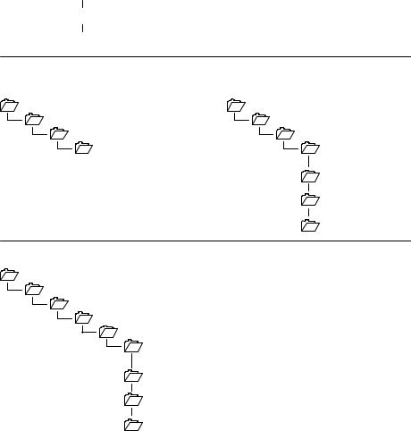
1.1.3File Information
When you installed the DoorKing Remote Account Manager, the software automatically created a folder (directory) named DoorKing in the Program Files folder. Each account that you establish creates a sub-folder in the DoorKing Account Manager folder starting with ACCT0000. The respective account files are then stored under the account sub-folder.
Windows XP
 C:
C:

 PROGRAM FILES

 DOORKING 32

 ACCT0000
 ACCT0001
 ACCT0002
Windows Vista / Windows 7 / Windows 8 – Just Me
Program Files Data Files
C: |
C: |
PROGRAM FILES |
PROGRAMDATA |
DOORKING |
DOORKING |
DOORKING ACCOUNT |
DOORKING ACCOUNT |
MANAGER |
MANAGER |
|
ACCT0000 |
|
ACCT0001 |
|
ACCT0002 |
Windows Vista / Windows 7 / Windows 8 – Everyone |
|
C: |
|
USERS |
|
PUBLIC |
|
PUBLIC DOCUMENTS |
|
DOORKING |
|
DOORKING ACCOUNT |
|
MANAGER |
|
ACCT0000 |
|
ACCT0001 |
|
ACCT0002 |
|
Page 8 |
1835-066-N-7-13 |
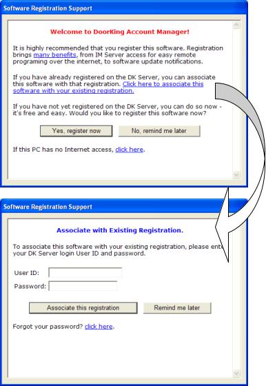
1.1.4Software Registration with an Existing DK Server Registration
When you first open the Account Manager software, you will receive a prompt to register the software.
Already Registered
If you already have a registration from an earlier version of the Account Manager software, you do not need to create another. Use “Click here to associate this software with your existing registration” to continue.
(If you have never registered any software on the DK Server, go to section 1.1.5.)
Login
Enter your existing user name and password and click “Associate this Registration.”
1835-066-N-7-13 |
Page 9 |
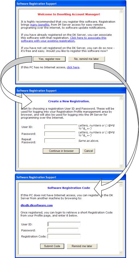
1.1.5New Registration
To register the software, we highly recommend that your PC has an internet connection. This will greatly simplify the registration process.
Internet Connection
If the PC does have an internet connection (recommended), click the “Yes, register now” button to create a new registration.
If the PC does not have an internet connection, you can click “this PC has no internet connection” to continue.
Page 10 |
1835-066-N-7-13 |

Once a user ID and password are created, your web browser will open to the DKS Software Registration page.
Complete the form to register the software. Your user name and password you entered will already be filled in for you. Click the “Register” button when finished.
1835-066-N-7-13 |
Page 11 |
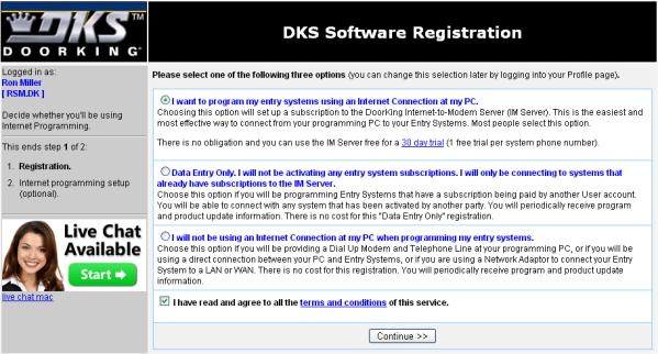
Select the option that best describes what you want to do, then click “Continue”.
If you select either option 2 or 3, the registration of the software is complete.
If you selected option 1(using the IM Server to program your entry system), you will then be directed to activate the entry system in the IM Server. See section 1.1.6.
Page 12 |
1835-066-N-7-13 |
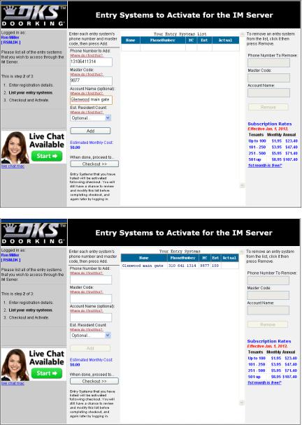
1.1.6Entry System Activation
If you have chosen to use the DoorKing IM Server to program your entry system, then the system must be activated in the IM Server first. Enter the following information in the spaces provided on the left hand side of the system activation screen.
Enter the 11-digit telephone number (1 + Area Code + Number) of the phone line connected to the entry system. This information is required.
Enter the 4-digit entry system Master Code. This information is required.
Enter a descriptive name for the system (Optional).
Enter the number of residents that the entry system serves (Optional).
Click “Add” when completed.
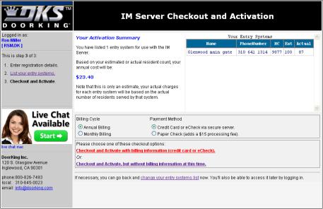
The entry system will be shown in the Entry Systems List.
Repeat the above steps to add additional entry systems, or click “Checkout.”
1835-066-N-7-13 |
Page 13 |
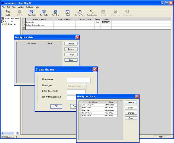
The checkout screen shows the estimated annual cost of using the IM Server to program your entry system.
Select the billing cycle and payment method.
To finish, choose one of the checkout options.
Checkout and Activate with Billing Information (credit card or eCheck)
This choice completes the activation of your system. You will receive the first 30 days free and subsequent payments (either monthly or yearly) are automatic.
Checkout and Activate, but without Billing Information at this time
This choice activities your system for the 30 day free trial period. After the 30 day free trial period, you will no longer be able to use the IM Server until billing information is received.
Page 14 |
1835-066-N-7-13 |
1.2Getting Started
1.2.1Security (Permission) Levels
Security (permission) levels allow you to set individual door/gate access times for residents using a wiegand device (Card, RFID, PIN, etc.). An example of this would be a gated apartment community that has a vehicular entry gate, a pedestrian access gate, a pool gate, a laundry room door, tennis court gate, office door, etc., where entry is controlled by a card reader. Security levels can be created that would allow residents access through the vehicular entry gate and pedestrian access gate 24 hours a day, 7 days a week, access to the pool and tennis court from 9:00 AM - 10:00 PM 7 days a week, access to the laundry room 7:00 am - 11:00 PM 7 days a week, and access to the office 9:00 AM - 6:00 PM Monday through Friday only.
Security levels are not assigned to the access control device. They are assigned to the individual user. In this manner, different security levels can be created allowing different access times to different users through a single access point. For example, this could be applicable in a controlled office (or factory) environment where different employees have different working hours.
There are 31 security levels available in the software program. The first two (Security Level 00 and 01) are factory set and are not programmable. Security Level 00 (SL00) will deny access at all controlled access locations to the user(s) that it is assigned to. An example of using SL00 would be a tenant in an apartment building who has been evicted and is no longer allowed entry to the building or any other controlled access point within the building. Security Level 01 (SL01) is the opposite of SL00, and will allow access to users that it is assigned to 24 hours a day, 7 days a week. An example of using SL01 would be for management or maintenance personnel who need to have full access to ALL locations at ALL times.
The remaining 29 security levels (SL02 - SL30) allow you to setup four different time zones for each level, and allow you to select the controlled access point(s) that it applies to. In the example given in paragraph 1 above, four different time zones where created under a single security level, and then the controlled entry point(s) that the time zone applies to were selected. The security level was then assigned to the individual residents.
When anti-pass back is in use, residents must be assigned a security level between 02 and 27. These security levels can be limited by the APB feature when it is turned on. Security levels 01, 28, 29 and 30 are not limited by APB.
Note: When using the Holiday schedule feature, the software will automatically convert Time Zone 4 in each security level to conform to the Holiday Schedule. TZ-4 on the security level page will then be labeled HOL. Security levels are not available on the Model 1834.
1.2.2Elevator Control
The elevator control feature determines which elevator(s) in a building a guest or resident will be allowed to use, and to which floor(s) the resident or guest will be allowed to go to, under certain controlled access conditions. In its most common use, when a resident grants access to a guest in a high rise apartment building, the system will call the designated elevator(s) to the ground floor, and then only the floor button that the resident resides on will be active in the elevator(s). This prevents the guest from accessing other than the designated elevator(s), or from going to unauthorized floors.
Elevator control can also be applied to residents to control which elevator(s) they can use and to which floor(s) they are allowed access too. In this application, a card reader is installed inside the elevator(s) car. When the resident enters the elevator, they must use their access card to "turn on" the elevator buttons. The buttons that will be turned on are set in the software. Security levels can also be applied in this application. As an example, suppose a resident lives in a high-rise apartment building. On the 20th floor of this building is a workout room that is only open 7 days a week from 6:00 AM to 11:00 PM only. Elevator control and security level control can be employed to allow residents access via the elevator to the workout room at the designated days and times only.
Note: Elevator control is not available on the Model 1834.
1.2.3Hold Open Time Zones
Seven different time zones can be created to "Hold Open" the door or gate at a controlled access point. An example of using this feature would be to hold open a vehicular access gate during "rush hour" traffic, unlock an office door during normal working hours, etc. Hold open time zones can be applied individually, or in any combination to each controlled access point(s). The eight hold open time zone is labeled HOL for “Holiday.” This time zone takes precedent whenever a “Holiday” date is present.
1835-066-N-7-13 |
Page 15 |
1.2.4Holiday Schedule
32 different “Holidays” can be set up in the software program. Whenever a holiday is present, the software will look first at the HOL schedules in the Hold Open Time Zones and the Security Levels. For example, if a holiday is created for Christmas Day, the software will revert to the HOL hold-open time zone on December 25th.
1.2.5Transactions
Transactions are automatically saved each time that they are received from the 1833, 1834, 1835, 1837, or 1838. Each time transactions are received, the software will automatically create a file name for them starting with TRANS0000. The file number will increase sequentially to a maximum TRANS9999. When 9999 files have been created, prior to receiving the next transaction file, the software will overwrite the old TRANS0000 file with the new transaction information and will delete file TRANS0001. The next transaction file that is received will be stored in the now empty TRANS0001 file and the information in TRANS0002 will be deleted to make room for the next transaction file. This sequence repeats itself sequentially.
Transactions are stored under their respective account sub-folders. This prevents transactions from one account being mixed up with transactions from another account. Each account can therefore have up to 9999 transaction files stored as described above.
1.2.6Live Transactions
Transactions can be viewed on the computer screen as they happen. Live transactions require an RS-232 connection between the PC and the access controller or LAN option and a TCP/IP connection to the controller using a DKS TCP/IP connection kit (P/N 1830-175).
1.2.7Live Streaming
Live streaming provides data that can be captured and used by other software applications. Live streaming requires an RS-232 connection (use P/N 1818-040 cable) between the PC and the access controller, or LAN option and a TCP/IP connection to the controller using a DKS TCP/IP connection kit (P/N 1830-175).
1.2.8Anti-Pass Back
The anti-pass back feature in this software program is TRUE anti-pass back. TIMED anti-pass back is not available. True anti-pass back can be set up in one of three different modes. PASSIVE anti-pass back will record APB violations but will allow the offending card access. ACTIVE anti-pass back will record APB violations but will not allow the offending card access. TRAP anti-pass back will record the APB violation, and will allow the card access at the entry, but deny access at the exit. Anti-pass back is not available on the 1834.
1.2.9System Administrator / Data Entry Users
There are two types of users that can be set up with passwords. The system Administrator has access to all the features of the software program and can set up security levels, hold open times, elevator control, etc. Data Entry users are limited to daily tasks such as adding or removing resident names and sending data to the system.
System Administrators and Data Entry users are created in the Log In screen which is accessed by the USERS button on the account screen. If users are set up, the first one MUST be an Administrator. Multiple administrators and users can be set up.
1.2.10Port Configuration
If using a modem to send and receive data, the software will automatically set the modem to operate under COM 2, 2400 Baud rate, and will install a set-up string that is common to most modems. If your modem is installed on another com port, or if you need to enter any special set-up strings, click the CONFIG PORTS button on the accounts screen. The port configuration window will appear and allow you to make the necessary adjustments, or use the auto-config button that will set up the software to respond to your modem installation.
If using the DKS server option to send and receive data, click the Test Server Connection button to insure that an internet connection is made between your computer and the DKS server.
Page 16 |
1835-066-N-7-13 |
1.2.11Clock Setting
Each time contact is made with the entry system from the computer, the clock / calendar in the entry system is automatically updated to match the clock information from your PC. Be sure that your computers clock / calendar is set to the correct time and date.
1.2.12Prior to Programming
The DoorKing Remote Account Manager can manage up to 10,000 separate accounts. By definition, an "account" is any 1833, 1834, 1835, 1837 or 1838 system that you are going to program with this software. Each unit must have a unique account name set-up for it, even if the unit is sharing the phone line with another DoorKing system. If this is the case, you must be sure that the master codes of each unit sharing the line are set differently. You must also set the software for multiple systems sharing a line by going to the SYSTEM INFO screen and clicking the YES button next to the multiple systems line.
The following hardware (entry system) parameters cannot be set with the software. These parameters must be set and programmed into the entry system from the system keypad, or they are factory set limits or features which cannot be changed remotely. The entry system should be tested to be sure that it is operating properly. It is very important that the phone line connected to the entry system is free of any hum, noise, or other interference that could cause modem communication problems. Refer to the installation and maintenance manual that was included with the 1833, 1834, 1835, 1837 or 1838 system to program the following parameters.
1.The system Master Code (default is 9999).
2.10 or 255 Area Codes (default is 255). 255 area codes are available on REV E or higher circuit boards only. REV D and lower boards have only 10 area codes available.
3.Single or multiple systems sharing the same phone line (default is single).
4.Match the memory size of the chips sent with the unit (default is 3000). The memory size cannot be set from the software program.
5.Call-up operation (default is OFF).
1.2.13Start the Program
The account screen is the main screen that you come to after entering the program. This is where most of your work will be done after you have set-up your account(s), programmed your system information and entered your resident data. From the account screen, you will be able to program the entry system, receive information from the remote system, and receive transactions to your PC.
To use the DoorKing Remote Account Manager to program your entry systems, you will perform the following three basic steps.
1.Create an account for the access system.
2.Enter the access system information.
3.Enter the resident (user) data.
1.2.14Series Column
The last column on the account screen is the SERIES column and is indicated by the letter S. This column will indicate either”30” or "4E" depending on which series control board was selected when the account was created.
1835-066-N-7-13 |
Page 17 |

SECTION 2 – ACCOUNT MANAGEMENT
To begin using the DoorKing Remote Account Manager to program your 1833, 1834, 1835, 1837, or 1838 systems, you must first create an ACCOUNT under which all the relevant account information (resident user data, transaction files, etc.) will be stored.
By definition, an ACCOUNT must be created for every 1833, 1834, 1835, 1837 or 1838 system that will be programmed with the Remote Account Manager software (up to 10,000 accounts can be managed with this software). Two or more units cannot share the same account name, even if they are sharing the same phone line. However, different accounts may share a common resident database (Section 2.2).
2.1Account Information
1.Start the Remote Account Manager Software program. While the program is loading, a DoorKing logo will appear on your screen.
2.The ACCOUNT screen will appear on your screen (fig 1). An account named “Example” has already been created.
Figure 1
Page 18 |
1835-066-N-7-13 |
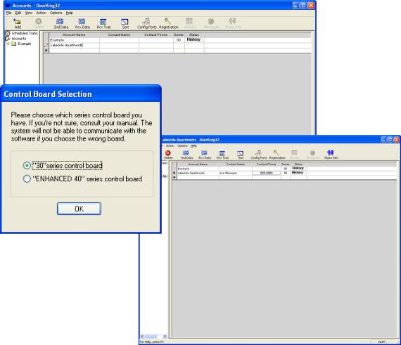
2.1.1Creating User Types
There are two types of users that can be created in the program; Administrators and Data Entry. Administrators have access to all levels and features of the program while Data Entry users are limited to daily tasks such as adding or removing resident names and sending updated information to the access system. When creating user types, the first one MUST be an Administrator. Up to 20 Administrators and 20 Data Entry user types can be entered in the program.
1.Under OPTIONS, select USER INFO from the pull down menu to display the Modify User window.
2.Click the CREATE button to display the Create the User window.
3.Enter the administrators name and create a password (by system default, this first user MUST be an administrator; therefore the user type is defaulted to this). Click OK when done.
4.Enter additional names and passwords as required. Once the first name is entered, you can now select the user type from the pull down menu. Up to 20 administrators and 20 date entry users can be created.
5.When complete, click CLOSE on the modify user screen to return to the ACCOUNT screen.
Figure 2
1835-066-N-7-13 |
Page 19 |
2.1.2Creating a New Account
1.With the ACCOUNT screen displayed, place the cursor in the empty name field (below example) or click the ADD button in the tool bar. Enter the new account name and press the TAB or ENTER key.
2.The CONTROL BOARD SELECTION window will appear. You must select the type of control board installed in the system that you are going to program. Click “30 Series” to program 1833, 1834, 1835, 1837 or 1838 systems. After selecting the control board series, click OK.
3.Complete your new account information by entering the account manager’s name and phone number.
4.Repeat steps 1-3 to create up to 99 additional accounts.
5.If more than one account is displayed on the screen, click the SORT button to list the accounts in alphabetical order.
Figure 3
Page 20 |
1835-066-N-7-13 |
2.1.3Editing Account Information
1.Click on the account that you want to edit and make the necessary changes.
NOTE: Editing an account here changes only the account name and contact information. It does nothing to change any of the resident, system, time zone, security level, etc. information associated with the account.
Figure 4
2.1.4Deleting Accounts
1.Click on the account that you want to delete.
2.Click the DELETE icon from the tool bar or click FILE then DELETE.
3.A warning will appear asking if you are sure that you want to proceed.
4.Click OK to delete the account or click NO to return to the account screen without deleting the account.
WARNING: When you delete an account, all the system information and resident data contained in the account folder (sub-directory) will also be deleted. Prior to deleting the account, you may want to copy the account data onto a CD. This will enable you to restore the resident data easily if it becomes necessary at a later date to reestablish the account.
To copy the data, you can use Windows Explorer to copy the information in the account folder to a CD. Refer to your Windows User's Manual for instructions on copying files and see section 6.3.2.
You can also use the BACKUP command. Refer to section 6.2.1.
1835-066-N-7-13 |
Page 21 |
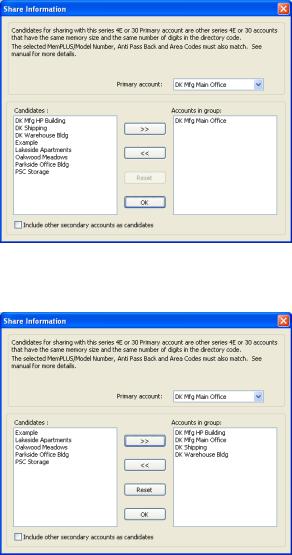
2.2Share Information Feature
The SHARE INFO feature allows more than one "account" to share its database with other accounts. The share info feature is useful in applications where there is more than one entry point and the entry points will all have identical user data. For example, if an apartment complex had a front and rear entry door (or gate), and an 1833, 1834, 1835, 1837 or 1838 system was installed on each entry point, the share info feature lets you use and maintain a single database for both entry location. 30 Series and Enhanced 40 Series accounts can share the user database with each other, but each account must have the same memory and number of digits in the directory code set identically. Also, accounts using the APB feature cannot be shared with non-APB accounts, and vice-versa.
1.From the accounts screen, click the account name that is the primary account, then click the SHARE INFO icon in the tool bar. The share info screen will appear with the primary account listed in the accounts group (Fig 5). In the example, DK Mfg Main Office was selected as the primary account. Notice that this account name is shown as the primary account in the upper right hand corner of the share information window, and that this account is listed in the "Accounts In Group" window on the right side of the screen. To change the primary account, click the arrow button on the primary account window, then scroll up or down and select a new primary account.
2.From the candidates list, click the account that you want to share the primary account user data base with, and then click the right ( >>) button to place the account in the accounts group. In the example, DK Mfg HP Bldg, DK Warehouse Bldg and DK Shipping have been placed in the "Accounts In Group" window (Fig 6). These accounts will now share the user database associated with the primary account - DK Mfg Main Office.
3.Select other candidate accounts as required. When complete, click the CLOSE button.
4.To remove an account from the Accounts In Group, click on the account you want removed, and then click the << arrow button. This will lace the account back in the candidates list and it will no longer share the user data with the primary account.
5.When a candidate account is selected to share information with a primary account, the account is removed from the candidate list, even if a different primary account is chosen, unless the "Include Other Secondary Accounts As Candidates" button is turned ON (X appears in the button window).
Figure 5
Figure 6
Page 22 |
1835-066-N-7-13 |

2.3Communication Port Configuration
If you are using a modem, the Port Config tab in the Program Configuration window is provided if you need to enter any special modem setup strings that may be applicable to your modem (refer to the manual that came with your modem). If you are using a DK IM Server for programming, there is a Test DK IM Server Connection button that will verify that your computer will connect to the DoorKing server. If you are using the DK IM Server, you will need to register as a user (see 2.3.2).
IMPORTANT: If using a LAN method to connect, you must have a TCP/IP kit (P/N 1830-175) installed on the access system control board.
NOTE: Typically, you will not need to make any adjustments to your port configuration, and therefore no changes need to be made. You should only make adjustments in these settings if you are experiencing problems in communicating with the entry system.
2.3.1Communication Configuration
1.Click the CONFIG PORTS icon in the tool bar. The port configuration window will appear (Fig 7).
2.Select the Port Config tab.
3.If you are using the DK IM server to send and receive data (see 2.3.2), click the Test DK IM Server Connection button to insure your computer can connect to the server.
4.If using an RS232 connection, set the rate to 9600 (default) or 19200. This rate must match the rate of the device connected to the RS232 port and the access controller.
Note: 19200 baud rate is only available with 30 Series circuit boards, REV M (or higher) for 1833, 1834, 1835, 1837, and REV L (or higher) for the 1838. Leave the baud rate set to 9600 for all other 30 Series circuit boards.
5.If you are using a modem to send and receive data, make the adjustments to the port setup as required (refer to your modem manual) or click the Auto Detect Port button.
6.Click OK to proceed with the changes or click CANCEL to
return to the accounts screen without any changes being |
Figure 7 |
|
made. |
||
|
2.3.2Software/Server Registration
1.If you are going to use a DK IM Server for programming, and you have not yet registered the software, click “Click here to register now” link and follow the instructions to register the software and to create a user registration (see 1.1.5).
Figure 8
1835-066-N-7-13 |
Page 23 |

SECTION 3 – SYSTEM MANAGEMENT
Once an account(s) has been created, the access control system information must be programmed. This information includes setting the entry system parameters, labeling the system relays for each entry point, using or ignoring card (access device) facility codes, mass enabling device (card, transmitter, etc.) codes, creating security levels and time zones, creating hold open times, creating a holiday schedule and programming the elevator control parameters if elevator control is used.
The control board series that was chosen when you first created an account (2.1.2) will affect how the entry panel is programmed. This chapter and the illustrations in it, addresses programming an entry panel with a 30 Series control board. If you are programming an entry panel with the Enhanced 40 Series board, refer to version 5.6 of this manual.
3.1Entry Panel Programming
The first step in system management is to program the entry panel system parameters. The entry panel can be a model 1833, 1834, 1835, 1837 or 1838 depending on your specific needs. The Remote Account Manager software is designed to address all of these entry panels, therefore some programming steps will be slightly different for the different panels.
1.On the account screen, select the account that you want to program the system information for by clicking on the account name, or selecting it from the accounts listed in the sidebar.
2.From the sidebar, click the + sign next to the account folder, then click the System folder to display the System Information screen. You can also navigate to this by selecting View and then Accounts (Fig 9).
Figure 9
Page 24 |
1835-066-N-7-13 |
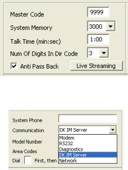
3.1.1Entry Panel Setup (Fig 10)
1.Enter the four-digit MASTER CODE in the field provided. The master code entered here must match the four-digit master code that has been programmed into the entry panel.
2.Select the SYSTEM MEMORY. The system memory must match the memory size of the chips installed in the entry panel.
3.Set the system TALK TIME.
4.Set the DIRECTORY CODE DIGITS.
5. Check ANTI-PASS BACK for 1833, 1835, 1837 and 1838 (APB is standard in these systems). Un-
check this box if you are programming an 1834 (APB is unavailable in the 1834).
3.1.2Communication Setup (Fig 11)
1.Select Modem, RS-232, DK IM Server or Network1 from the pull-down menu (The diagnostics option is used only when you are talking with a DKS technician on the telephone).
Note 1: Requires installation of TCP/IP kit on the system (P/N 1830-175).
Figure 11
2.If Modem or DK IM Server was selected, enter the SYSTEM PHONE number in the field provided.
Include the area code if 10-digit dialing is required in your area. When using the DK IM Server, you MUST include 1+Area Code+ Phone Number.
3.If Network was selected, you will need to enter the static, dynamic or local IP address and the port number (separated by a colon) in the System IP Address field.
Example: hostname.dyndns.org:1040 Example: 192.168.1.40:1040
4.Select either the 1834 model, or the 1833, 1835, 1837, 1838 models.
5.Select either 10 or 255 Area Codes. The number of area codes selected here must match how the entry panel area code option was programmed; either 10 area codes or 255 area codes. 255 area codes are only available on REV E or higher circuit boards.
6.If the entry system is set-up on a PBX or KSU and it needs to dial a “9” to get a dial-tone, enter the number where indicated.
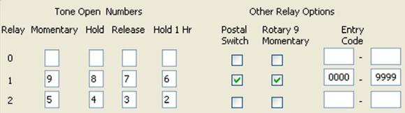
3.1.3Tone Open Numbers (Fig 12)
Tone open numbers are the numbers that the entry panel will respond to and will cause the programmed relay action that the tone number was set for. Tone open numbers can be set to activate a single relay or any combination of relays. Each relay has four tone open number fields that can be set, however when a call is made to a resident, the resident can only momentarily activate the relay - the system will not respond to other tone open numbers from a resident.
The other three tone open number fields (Hold, Release, Hold 1 Hr.) are functions designed for the system administrator and will cause the relay(s) in the entry panel to respond to the programmed command. To use these functions, the system administrator calls the entry panel via a touch-tone telephone, and then enters a series of numbers to cause the desired relay action (Refer to the Owner's Manual that came with the entry panel for instructions on using this feature).
NOTE: The 1834 and 1838 Entry Panels do not have RELAY 0 capability. Leave all Relay 0 fields blank if programming an 1834 or 1838 entry panel.
1835-066-N-7-13 |
Page 25 |
1833, 1835, 1837 ENTRY PANELS
If Tracker™ expansion boards are used with the 1833, 1835 or 1837 entry panels, set the tone open number(s), postal switch and rotary dial 9 inputs to activate RELAY 0. Relay 1 and Relay 2 are used as Tracker™ board command relays in this configuration.
1838 ENTRY PANELS
Generally, tone open numbers do not need to be set when using the 1838 entry panel because this panel is not designed for any voice communication requirements. However, it may be desirable to program tone open numbers for Relays 1 and 2 (there is no Relay 0 in the 1838, leave these fields blank) so that the system administrator can unlock doors (or open gates) under abnormal situations. For example, if a tone number is entered in the HOLD and RELEASE fields for Relays 1 and 2, a system administrator could use this function to command ALL doors and gates connected to the system to unlock (or open) in an emergency situation by calling the 1838 from a touch-tone telephone and entering the hold open tone command. This function requires that a CO telephone line be connected to the 1838 system for communication. This function is not available if RS232 is the only means of communicating with the 1838 system.
Figure 12
1.Enter the tone open number for each relay under the desired function for that relay. If a function is not desired, leave it blank.
2.Select which relay(s) will activate when the postal switch is activated and when the entry panel detects a rotary dial 9.
3.1.4ENTRY CODES
Do not confuse four-digit ENTRY CODES with five-digit PIN codes. An ENTRY CODE is a four-digit number assigned to an individual and is entered in the entry code field on the resident information screen. Entry codes will activate the relay on the entry panel control board that it is programmed for when the code is entered on the entry panel keypad only. PIN (Personnel Identification Number) CODES are five-digit codes that are assigned to an individual and are entered in the device code field on the resident information screen. The relay that the PIN code will activate is determined by which wiegand input the PIN keypad is connected to and security level programming.
1.If entry codes are used, lower and upper ranges can be programmed which will cause the entry code to activate the desired relay(s). NOTE: Entry code ranges may overlap allowing one entry code to activate any combination of relays.
2.Enter the lower and upper boundary four digit entry code number for each relay.
Page 26 |
1835-066-N-7-13 |
Loading...