

DoorKing 1175 Installation & Owner's Manual
Installation/Owner’s Manual
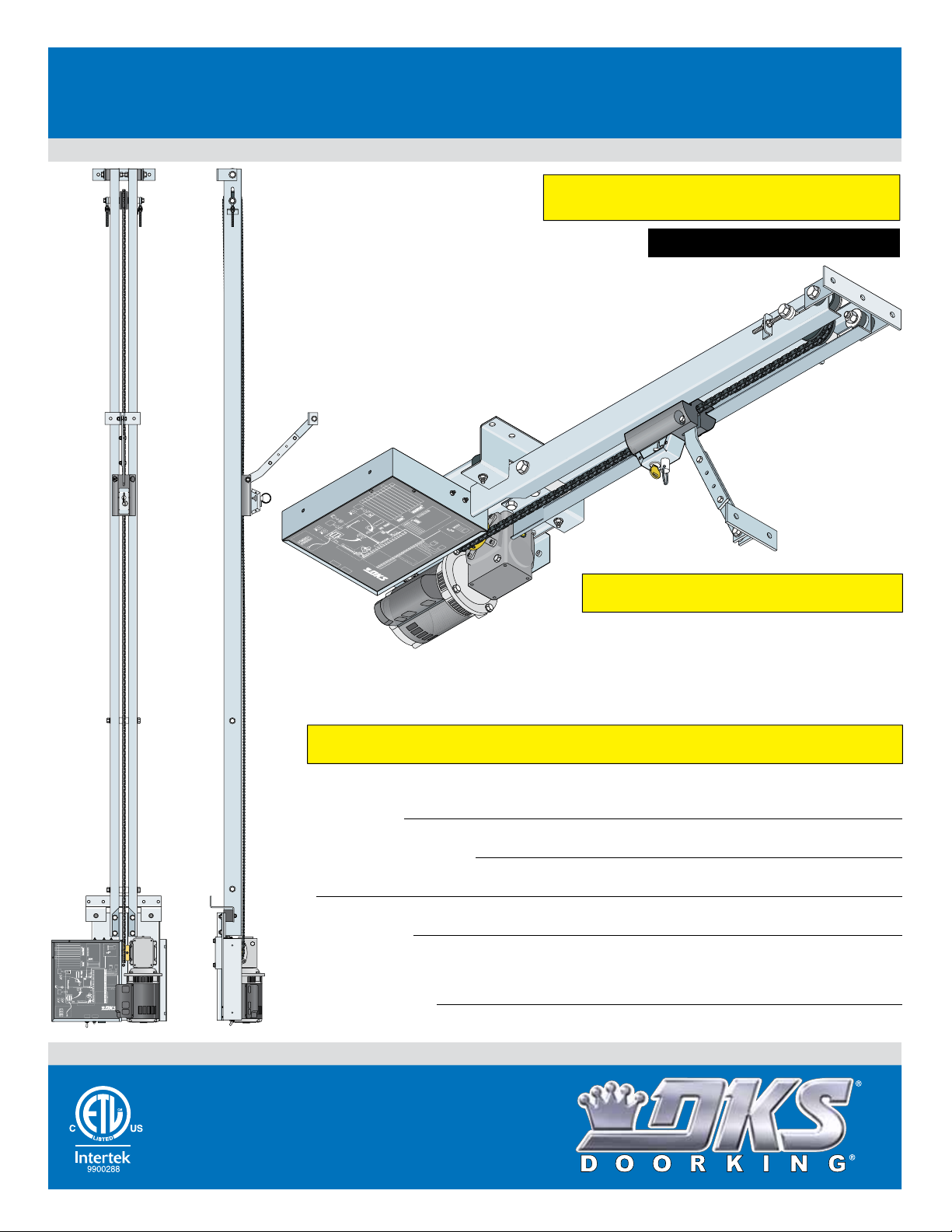
Model 1175
Commercial Overhead Gate/Door Operator
Model 1175
Model 1175
Use this manual for circuit board 4405-018 Revision A or higher.
1
S
et
**
2
o
p
s
o
e
n
op
O
3
co
FF
e
r
m
a
O
N
t
m
o
F
4
o
r
a
O
F
t
n
c
N
U
yc
d.
T
O
s
e
Te
l
e
e
r
F
5
d.
m
s
O
F
r
m
O
N
4
A
P
4
u
A
i
***
s
E
O
t
6
u
i
o-
s
N
E
FF
t
o
Cl
x
F
u
-Cl
i
ul
t
po
N
o
7
O
Lo
l
s
&
o
ose
n
e
O
F
t
8
in
o
F
U
p
Ti
p
e
S
it
s
T
N
m
L
i
n I
e
w
a
i
ot
m
o
e
d
de
l
i
g
r
t
.
n
p
1
e
c
U
i
is
o
p
t
r
c
h
er
w
s
u
i
e
O
O
s
ed
t
e
s
m
F
u
O
(N
r
O
7
i
.
t
2
O
3
F
O
4
F
F
N
O
o
N
t
S
w
D
i
t
c
K
h
S
E
M
x
L
i
U
D
t
oo
S
et
p
e
Ti
c
0
t
m
o
2
r
e
3
r
S
ec
M
i
n
R
el
M
a
y
a
x
C
o
nt
act
N
C
N
O
D
R
K
e
S
v
e
L
r
D
o
se
o
et
p
e
c
t
o
r
N
o
U
t
s
e
d
R
e
S
M
v
e
i
ns
n
M
a
x
M
i
n
I
M
n
a
11
put
x
N
5
E
P
V
U
ow
A
TR
C
A
er
O
L
nl
H
O
y
T
W
H
I
TE
B
L
A
C
K
G
R
E
EN
C
G
A
r
ou
U
n
TION
d
–
Hi
g
h
Vo
lt
a
g
e
C
!
i
r
c
u
C
i
t
i
r
c
u
i
P
t
B
o
o
S
a
we
w
it
r
c
h
R
es
B
u
et
tto
n
M
od
M
o
el
del
44
1
0
175
5
0
1
0
C
ont
P
/N
1
1
5
0
0
u
F
n
N
p
o
F
p
&
.
e
u
r
F
(
a
t
m
w
8
N
.
n
N
h
o
a
d
w
ot
e
r
l
ork
m
n
S
F
U
a
e
t
h
l
s
t
i
N
ti
n
e
S
e
n
ot
d
e
c
r
g)
el
.
o
t
t
U
n
i
ay
n
sed
j
u
g
n
)
w
.
c
.
i
t
ll
U
i
on
a
sed.
c
w
t
i
vat
i
t
1
h
e
e
23
O
a
.
N
c
S
h
e
o
T
45
e
t
M
h
b
m
e
e
O
N
f
o
r
M
o
d
e
l
1
1
7
5
.
S
W
1
S
W
2
M
o
n
C
i
E
t
o
o
x
nn
r
te
e
rn
d
e
c
a
t
I
n
i
l
o
p
n
u
t
s
*
*
*
L
ow
V
L
ow
o
l
ta
V
o
l
t
a
g
e
C
N
o
t
U
A
la
rm
R
1
es
e
Mo
t
1
6
t
o
M
B
r
o
1
o
a
7
t
o
r
d
r
1
P
8
w
r
d
r
19
P
w
r
2
0
T
e
H
i
gh
O
p
er
at
or
r
ol
B
oar
d
0
6
D
2
/
1
7
O
C
r
a
N
l
an
6
nu
o
I
TO
s
d
7
a
e
l
.
RE
8
B
M
e
U
a
D
m
S
C
1
T
R
O
b
O
ev
N
e
2
p
N
er
e
c
C
E
n
o
se
3
C
l
n
B
o
n
TI
se
e
(
O
ec
Te
a
O
4
p
m
B
N
t
e
r
e
e
m
C
n
S
S
d
am
5
l
2)
t
E
o
!
op
1
s
dge
L
e
R
o
2
O
6
E
e
w
N
/
v
d
3
B
L
V
e
ge
o
e
rse
o
4
w
a
N
lt
/
m
B
a
Vo
O
e
g
R
a
e
lt
ev
m
ag
C
e
o
R
e
r
m
1
s
e
C
e
v
m
1
o
er
2
o
m
se
n
2
3
O
m
O
p
3
e
C
n
l
4
o
O
Be
se
p
en
C
B
l
e
o
am
E
s
e
dg
E
e/
d
B
g
e
/
B
e
a
m
L
o
w
V
o
lt
a
g
*
*
L
o
op
F
u
l
O
u
*
t
2
o
4
r
F
VA
u
P
l
l
ar
O
t
G
p
i
al
e
a
n
t
O
e
G
4
pe
R
Tr
a
e
t
n
acker D
e
v
e
5
T
*
r
*
s
r
*
a
e
D
c
6
k
r
a
e
y
t
r
a
R
B
D
N
el
7
u
r
o
y
a
s
t
y
y
U
R
C
8
el
se
o
a
n
d
y
t
a
9
C
g
c
e
o
t
n
10
C
ta
o
c
m
t
mo
11
o
m
n
1
m
*
2
*
o
*
n
d
O
e
1
p
p
Se
s
3
e
e
e
r
n
e
a
d
d
t
m
ion
e
1
n
a
t
4
n
o
o
u
f
n
a
t
l
h
S
f
e
W
o
5
r
r
1
e
m
,
lay
o
s
wit
r
i
in
s
c
fo
h
A
r
s
T
m
c
7
t
er
D
a
i
v
t
e
r
i
a
o
v
mi
e
t
n
ic
in
ser
.
e
g
o
nal
(
s
pe
)
v
n
s
ed
r
o
a
1
t
u
4
o
f
s
or
r
–
er
C
w
in
20
i
con
A
r
t
i
er
ng
a
U
nal
r
nect
:
e
T
r
m
I
O
io
i
N
n
n
s
a
.
Vol
l
s
16
t
a
ge!
–
20
3-
p
o
4
C
en
n
B
l
ose
u
C
t
S
t
om
o
t
o
a
m
S
t
o
R
e
v
ea
er
m
R
e
R
ev
e
r
e
C
o
m
m
l
O
p
e
n
C
3
&
8
.
n
m
p
C
o
on
n
p
3
B
u
t
S
e
se
u
t
s
j
u
e
s
mpe
d
ta
.
t
i
v
Se
o
r
e
n
t
r
o
t
w
se
N
t
N
o
i
o
t
h
O
r
3
s
m
-
a
RM
B
e
a
N
U
l
/
A
T
C
L
wh
s
w
t
o
h
e
p
e
n
n
c
a
i
rc
3
3-
-
u
b
i
b
t
u
u
i
t
s
to
t
t
u
o
n
s
n
i
e
s
c
d
n
o
.
n
o
t
t
r
o
l
o
n
1
2
F
ir
D
e
e
p
t
*
L
i
m
i
t
*
e
*
R
d
R
a
D
t
e
d
o
e
c
io
p
2
e
e
5
1
i
ve
n
0
d
r
m
a
2
n
a
t
M
o
3
n
a
x
S
.
W1
,
s
w
i
t
c
h
3
.
1175-065-H-8-18
EXTERNAL ENTRAPMENT PROTECTION MUST be
installed or the gate/door operator WILL NOT function.
UL 325 August 2018 Standard
t
r
o
l
THIS PRODUCT IS FOR INDOOR USE ONLY.
Install in a protected area NOT exposed to weather.
**
***
NEUTRAL
1
3
4
5 OFFNot Used.
6 OFFNot Used.
7&8
3 OFFNot Used.
4 ON Switch MUST be ON for Model 1175.
Timer
0-23 Sec
Relay Contact
Not
Used
MinMax MinMax
115 VAC Only
HOT
Set so operator cycles OPEN upon initial power up and
open command.
OFF Not Used.2
OFF Term 4 is Exit Loop Logic Output.
ON Term 4 is Full Open Input (Normal Setting)
OFF Auto-Close Timer is OFF.
ONAuto-Close Timer is ON (Normal Setting).
Switches 7 & 8 work in conjunction with each other and
determine when the relay will activate. See manual.
OFF Not Used.1
OFFNot Used.2
DKS
Exit
Loop
Detector
MinMax
NO
NC
DKS
Reverse
Loop
Detector
Rev
Sens
Input Power
WHITE
BLACK
GREEN
THIS PRODUCT IS TO BE INSTALLED AND SERVICED BY A TRAINED GATE/DOOR SYSTEMS TECHNICIAN ONLY.
Visit
www.dkslocator.com
to find a professional installing and servicing dealer in your area.
Date Installed:
Installer/Company Name:
3-Button Control
MONITORED CONNECTIONS
Close Beam Reverse (Term 2)
Open
MUST be connected!
ON
Close
12345678
Stop
1 Open Beam Stop
Common
2 Close Beam Reverse
3 Open Edge/Beam Reverse
Normal
3-But
4 Close Edge/Beam Reverse
5 Low Voltage Common
Set jumper to NORMAL when 3-button is not
used. Set to 3-BUT when a 3-button control
6 Low Voltage Common
station with a N/C stop circuit is used.
ON
1234
ON
1234
Open Beam Stop1
Close Beam Reverse2
3Open Edge/Beam Reverse
4Close Edge/Beam Reverse
Radio
Fire
Receiver
Dept
1 2 3
Low Voltage Common 1
Full Open 2
* Limited to 250 ma Max.
* 24 VAC 3
** Dependant on SW1, switch 3.
SW1
** Loop Out or Full Open 4
Partial Open 5
SW2
Reverse 6
Gate Tracker Data 7
Monitored
Gate Tracker Busy 8
External
Not Used 9
Connection
Inputs
*** Dry Relay Contact 10
*** Operation of the relay is
dependent on SW1, switchs 7 & 8.
See manual for mor information.
*** Dry Relay Contact 11
Low Voltage Common 12
Activating
Device(s)
Low Voltage Common 13
Alarm 14
Terminals 14 – 20 are
reserved for internal
Reset 15
operator wiring:
Not Used 16
no user connections.
Motor 17
CAUTION
Motor 18
Terminals 16–20
Circuit Board Pwr 19
High Voltage!
Circuit Board Pwr 20
CAUTION – High Voltage!
Model 1175 Operator
Model 4405-010 Control Board
Power
Reset
P/N 1150-006 D 2/17
Ground
Switch
Button
Phone Number:
Circuit Board
Serial Number
and Revision Letter:
Leave Manual with Owner
Copyright 2018 DoorKing, Inc. All rights reserved.
Conforms To UL STD 325
Certified To CSA STD C22.2 # 247
Copyright 2017 DoorKing, Inc. All rights reserved.
Copyright 2009 DoorKing, Inc. All rights reserved.

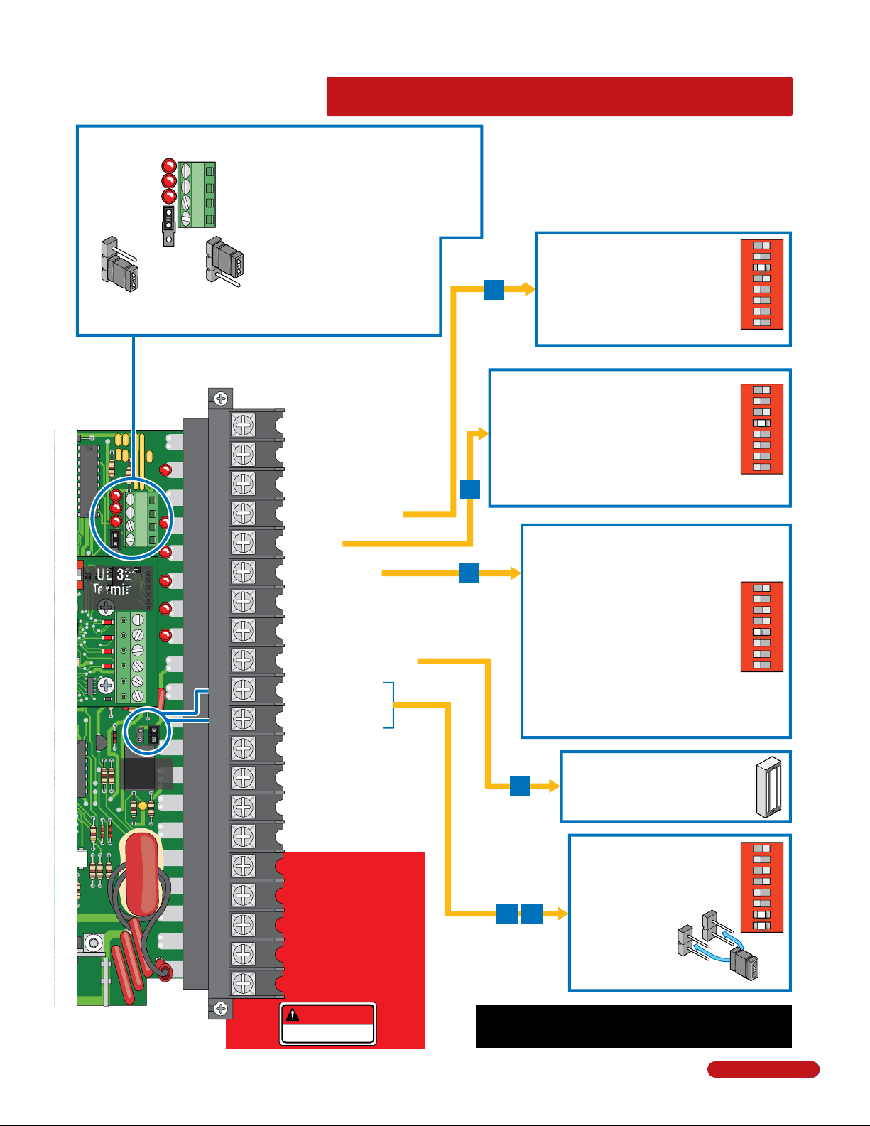
QUICK GUIDE: DIP-Switches
The two DIP-switches located on the circuit board are used to program the operator to operate in various modes and to turn on
or off various operating features. Whenever a switch setting is changed, power to the operator must be turned OFF and then
turned back on for the new setting to take affect. Check and review ALL switch settings prior to applying power to the operator.
SW 1 (Top 8 Switches)
Switch Function Setting Description
1
Opening
Direction
MUST be in ON Position.
2
3
4
5
6
7 and 8
Switch 1 Must OPEN upon initial AC power up and open command. Set to ON Position.
Switch 2 Leave in OFF position.
Switch 3 Determines that a device wired to terminal #4 is a normal full open command OR terminal #4 becomes the output
from the exit loop detector that is plugged into the EXIT Loop port in the circuit board (Used for specialized functions).
Switch 4 Turns the auto-close timer on or off. Maximum time that the close timer can be set for is approximately 23 seconds.
Switch 5 Leave in OFF position.
Switch 6 Leave in OFF position.
Switches 7-8 These work in conjunction with each other and determine when the relay on the board will be activated. This relay
can be used as a switch for various functions such as illuminating a warning light when the gate/door is moving, or turning on a
green light when the gate/door is full open.
OFF
Exit Loop Port
Output
Full Open Input
Auto-Close
Timer
OFF
OFF
Circuit
Board
Relay
Leave in OFF Position.
The output wired to terminal #4 becomes the output from the exit loop detector
OFF
plugged into the EXIT Loop port.
Normal Setting. Terminal #4 is a normal full open input.
ON
Auto-close timer is OFF. Manual input required to close gate/door.
OFF
Normal Setting. Auto-close timer is ON. Adjustable from 1-23 seconds.
ON
Leave in OFF Position.
Leave in OFF Position.
7-OFF
7-OFF
7-ON
7-ON
8-OFF
8-OFF
Normal Setting. Relay activates when gate/door is at open limit.
Relay activates when gate/door is not closed.
8-ON
Relay activates when gate/door is opening and open.
Relay activates during opening and closing cycle.
8-ON
SW 2 (Bottom 4 Switches)
Switch Function Setting Description
1
2
3
4
Switch 1 Leave in OFF position.
Switch 2
magnetic lock is used and connected to terminals 9 and 13. This applies magnetic lock power and logic to these terminals (NC).
Switch 3 MUST be in ON position.
Switch 4 MUST be turned OFF for the Model 1175.
2 Quick Guide - 1
OFF
Magnetic lock
ON
OFF
If a magnetic lock is not used with the gate/door operator, leave this switch in the OFF position. Turn this switch ON if a
Leave in OFF Position.
Normal Setting. Magnetic lock is not used.
OFF
Magnetic lock is used and connected to terminals 9 and 13. See page 17 for wiring.
ON
Switch 3 MUST be in ON Position.
Switch 4 MUST be turned OFF for Model 1175 operator.
1175-065-H-8-18
See page 17 for terminal wiring.
O
4-Pin Non-Removable Terminal
Open LED
Close LED
Stop LED
3-Pin with
Jumper
Jumper on bottom
2 pins when using
4-pin terminal.
1
Open N.O.
2
Close N.O.
Stop N.C.
3
Common
4
Jumper on top 2 pins
when NOT using
4-pin terminal.
• Use a standard 4-wire 3-button control
station mounted at least 5 ft above of the
floor and at least 6 ft from gate/door.
See page 13 for info about installation.
(DoorKing’s 3-wire 3-button control
station cannot be used)
• When using a 3-button control
station AND a interlock device
together, #3 terminal (N.C.)
must be wired in series.
• See page 17 for wiring.
QUICK GUIDE: Terminal Descriptions
ON
1
• lf SW 1, switch 3 is ON, functions as a
normal full open input (Normal setting).
4
• lf SW 1, switch 3 is OFF, input to
terminal #4 becomes the output from the
EXIT loop detector plugged into the EXIT
loop port. (Used for specialized functions).
2 3 4 5 6 7 8
SW 1
20-Pin Main Terminal
• When gate/door is closed, input will open gate/door.
• When gate/door is open and auto close timer SW 1,
1
2
2
1
2
3
4
4
1477-010
OB
CB
OE
CE
G
G
NC NO
5
6
7
8
N
UL 325
1
2 3 4
Terminal
Pages 12,17
3
4
5
6
7
8
9
10
11
12
Relay
Contacts
13
14
Low Voltage Common
Full Open
24 VAC - 250 mA max.
(See note below)
Loop Out or Full Open
Full Open
Standard Reverse
Tracker Data
Tracker Busy
24 VDC Mag Lock Power
Dry Relay Contact
Dry Relay Contact
Low Voltage Common
Low Voltage Common
Entrapment Alarm
switch 4 is turned ON, input will re-set and hold timer.
• When gate/door is open and auto close timer SW 1,
switch 4 is turned OFF, input will close gate/door.
• When gate/door is closing, input will reverse
5
gate/door.
This input ONLY functions when gate/door is
fully opened or in the closing cycle.
6
• When gate/door is closing: SW 1, switch 5
is OFF, an input to terminal #6 (N.O.) will stop
and reverse and the gate/door to the full open
position.
Note: If the auto-close timer is ON, when
gate/door reaches the open position, timer
will not close the gate/door. Another input
command is needed to reset and close the
gate/door (Normal Setting).
• SW 1, switch 5 ON, NOT used for gate/door operator.
24-volt DC magnetic lock power is
9
provided constantly except when the
gate/door is opening or open
(Normally Closed function). 1 Amp Max.
1
2 3 4 5 6 7 8
1
2 3 4 5 6 7 8
ON
SW 1
ON
SW 1
0
1175-065-H-8-18
15
16
17
18
19
20
20
Alarm Reset
Not Used
Motor
Motor
Circuit Board Power
Circuit Board Power
DANGER
HIGH VOLTAGE!
ON
NO
1
2 3 4 5 6 7 8
SW 1
Quick Guide - 2
Operation of the circuit board dry
relay contact is dependent on
setting of SW 1, switches 7 and 8.
Relay contacts can be set for
Normally Open (NO) or
10
11
Main Terminal #3 Note:
Exceeding 250 mA of power from this terminal may cause the circuit
board transformer to overheat, causing intermittent problems.
Normally Closed (NC)
operation.
Contact rating is
1 amp maximum
at 24-volts DC.
NC
3
SPECIFICATIONS
THIS PRODUCT IS FOR INDOOR USE ONLY.
Install in a protected area NOT exposed to weather.
For the Model 1175 with circuit board 4405-018 Rev A or higher ONLY.
Class of Operation Model 1175 - UL325 Class II, III and IV
Type of Opening Vehicular high traffic gate/door only.
Horsepower/ Voltage / Phase ½ HP - 115 VAC - 60 Hz. Single-Phase
Current 5.4 Amps
Max Gate/Door Dimensions Height - 14 Feet, Width - 25 Feet
Gear Reduction 40:1 Worm gear in a continuous oil bath.
Chain Type #40
Cycles Per Hour Continuous Duty
Speed Approximately 10 inches per second
Inherent Entrapment Protection Device:
Inherent Reverse Sensor System (Type A)
External Entrapment Protection Device Inputs (Monitored Inputs):
Monitored connection inputs for Non-contact Sensor - Photo Sensor (Type B1)
Monitored connection input for Contact Sensor - Reversing Edge (Type B2)
Mounting
Bracket
Setsooperatorcycles OPEN upon initial power upand
1
open command.
OFF Not Used.2
OFF Term 4 is Exit Loop Logic Output.
3
**
ON Term 4 is Full Open Input (Normal Setting)
OFF Auto-Close Timer is OFF.
4
ONAuto-Close Timer is ON (Normal Setting).
5 OFFNot Used.
6 OFFNot Used.
Switches 7 & 8 work in conjunction with each other and
7&8
***
determine when the relay will activate. See manual.
OFF Not Used.1
OFFNot Used.2
3 OFFNot Used.
4 ON Switch MUST be ON for Model 1175.
DKS
Exit
Loop
Detector
Timer
0-23 Sec
Min Max
Relay Contact
NO
NC
DKS
Reverse
Loop
Detector
Not
Rev
Used
Sens
MinMax Min Max
Input Power
115 VAC Only
NEUTRAL
WHITE
HOT
BLACK
Ground
GREEN
12345678
1234
SW1
SW2
CAUTION – High Voltage!
Installation of ONE EXTERNAL entrapment protection MONITORED device
MUST be installed in the DOWN direction or operator WILL NOT function.
TWO (2) Entrapment Protection Devices are REQUIRED in the DOWN direction
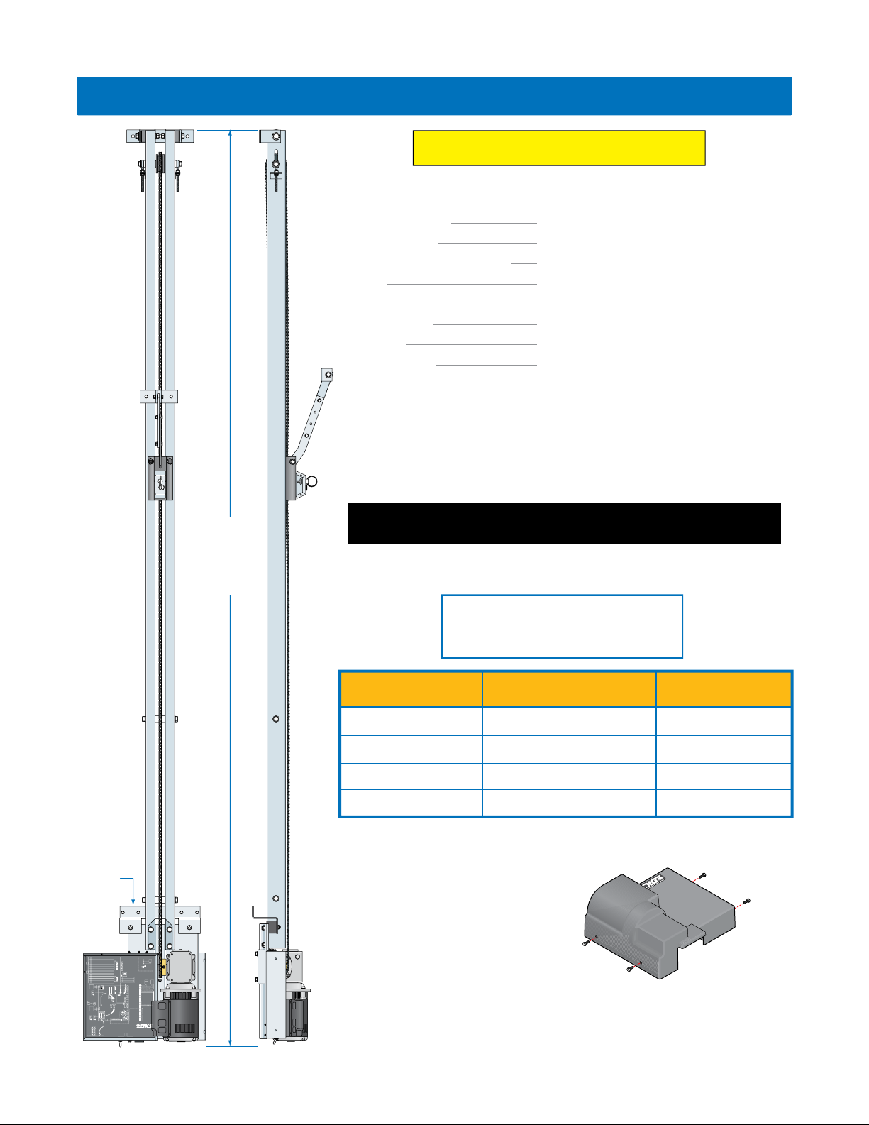
Dimension A
for UL 325 compliance. Type B1 and B2 MUST be MONITORED when used.
Type of wiring to be used on ALL external devices:
A) Type CL2, CL2P, CL2R, or CL2X.
B) Other cable with equivalent or better electrical,
mechanical, and flammability ratings.
Rail Part Number Max. Gate/Door Height Dimension A
1150-225
1150-226
1150-227
1150-228
8 feet
10 feet
12 feet
14 feet
IF the operator MUST be installed less than 8 feet (2.44 m) above the floor,
then exposed moving parts must be protected by covers or guarding, provided
by the operator manufacturer.
DoorKing offers a 1175 cover to protect
against anyone from coming in contact
with the operator’s exposed moving
3-Button Control
MONITORED CONNECTIONS
Close Beam Reverse (Term 2)
Open
MUST be connected!
ON
Close
Stop
1 Open Beam Stop
Common
2 Close Beam Reverse
3 Open Edge/Beam Reverse
Normal
3-But
4 Close Edge/Beam Reverse
5 Low Voltage Common
Set jumper to NORMAL when 3-button is not
used. Set to 3-BUT when a 3-button control
6 Low Voltage Common
station with a N/C stop circuit is used.
ON
1234
ON
Open Beam Stop1
Close Beam Reverse2
3 Open Edge/Beam Reverse
4 Close Edge/Beam Reverse
Radio
Fire
Receiver
Dept
1 2 3
Low Voltage Common 1
Full Open 2
* Limited to 250 ma Max.
* 24 VAC 3
** Dependant on SW1, switch 3.
** Loop Out or Full Open 4
Partial Open 5
Reverse 6
Gate Tracker Data 7
Monitored
Gate Tracker Busy 8
External
Not Used 9
Connection
Inputs
*** Dry Relay Contact 10
*** Operation of the relay is
dependent on SW1, switchs 7 & 8.
See manual for mor information.
*** Dry Relay Contact 11
Low Voltage Common 12
Activating
Device(s)
Low Voltage Common 13
Alarm 14
Terminals 14 – 20 are
reserved for internal
Reset 15
operator wiring:
Not Used 16
no user connections.
Motor 17
CAUTION
Motor 18
Terminals 16–20
Circuit Board Pwr 19
High Voltage!
Circuit Board Pwr 20
Model 1175 Operator
Model 4405-010 Control Board
Power
Reset
P/N 1150-006 D 2/17
Switch
Button
parts. Sold separately, P/N 1175-020
DoorKing, Inc. reserves the right to make changes in the products described in this manual without
notice and without obligation of DoorKing, Inc. to notify any persons of any such revisions or changes.
Additionally, DoorKing, Inc. makes no representations or warranties with respect to this manual. This
manual is copyrighted, all rights reserved. No portion of this manual may be copied, reproduced,
translated, or reduced to any electronic medium without prior written consent from DoorKing, Inc.
147 inches
171 inches
195 inches
219 inches
1175
Cover
4
1175-065-H-8-18

QUICK GUIDES
TABLE OF CONTENTS
Quick Guide: DIP-Switches
Quick Guide: Terminal Descriptions
SPECIFICATIONS
Overhead Gate/Door Protection
Gate/Door Construction
Important Safety Instructions
Instructions regarding intended installation:
Important Notices
UL325 Entrapment Protection
Glossary
Quick Guide - 1
Quick Guide - 2
Previous Page
3-4
SECTION 1 - INSTALLATION 7
1.1 Determine Location of Operator
1.2 Attach Rails to Powerhead
1.3 Manual Release and Chain Connection
1.4 Adjust Chain Tension
1.5 Attach Gate/Door Bracket
1.6 Attach Header Bracket
1.7 Mount Operator
1.8 External Entrapment Protection Installation
1.9 3-Button Control Station Installation
10-11
12
13
SECTION 2 - WIRING 14
2.1 Conduit Requirements
2.2 High Voltage Wire Run
2.3 High Voltage Terminal Connection
2.4 Main Terminal Description
2.5 Control Wiring
2.6 External Entrapment Protection Wiring
2.7 Loop Detector Wiring
14
15
15
16
17
18
19
2
3
3
4
5
6
7
7
8
8
9
9
SECTION 3 - ADJUSTMENTS 20
3.1 Circuit Board Adjustments
3.2 DIP-Switch Descriptions and Functions
3.3 Limit Sensor Adjustments
3.4 Inherent Reverse Sensor Adjustment
SECTION 4 - OPERATING INSTRUCTIONS 24
4.1 Power Switch and Alarm Reset Switch
4.2 Shutdown Conditions
4.3 Manual Gate/Door Operations
SECTION 5 - TECHNICAL INSTRUCTIONS 28
5.1 Maintenance Schedule
5.2 Diagnostics Check
5.3 Troubleshooting
5.4 Accessories
1175 Wiring Schematic
SECTION 6 - OWNER OF THE GATE/DOOR OPERATOR 33
8.1 Alarm Sounding and Gate/Door WILL NOT Operate
8.2 Manual Gate/Door Operation
8.3 Gate/Door Operators Monthly Checkup
Printable Safety Page
1175-065-H-8-18
20
21
22
23
24
25-26
26-27
28
28-29
29-30
31
32
33
34
35
37
1
Reverse Loop
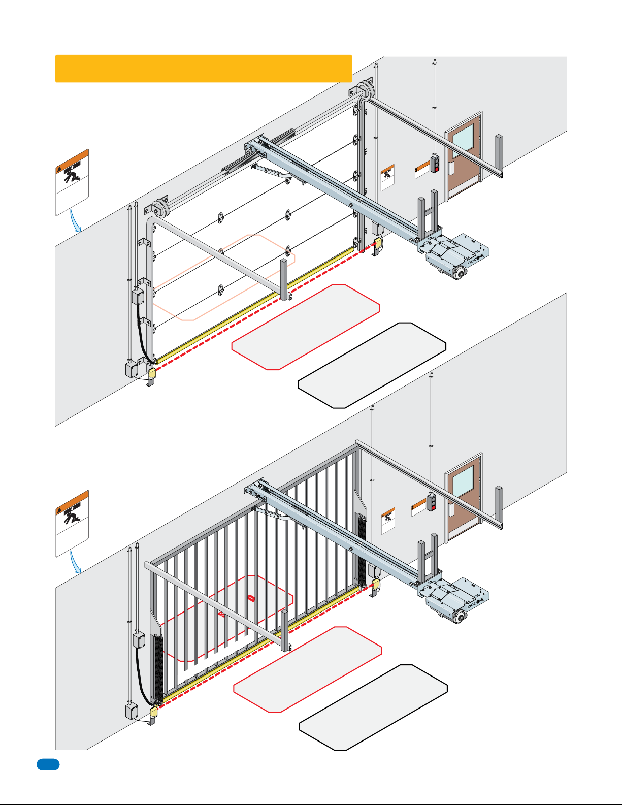
Overhead Gate/Door Protection
One or more contact or non-contact external MONITORED entrapment protection
systems shall be located where the risk of entrapment or obstruction
exists at either the opening or closing direction. Care shall be
exercised to reduce the risk of nuisance tripping, such as when
a vehicle trips the sensor while the gate/door is still moving.
Separate
Pedestrian
Entrance
!
Moving Gate Can Cause
Serious Injur
ns are to
Perso
e moved wit
to b
not le
a of
e
do
the ar
en
is
Th
Pedestria
childr
t
trance i
n
keep clear! The gate i
en
the gate.
s
s must use a se
y or Deat
ior warning.
he ga
t
out pr
h
y.
operate
e entrance
arat
p
vehicles onl
or
f
Mounted outside
h
structure an
e
l
ab
s
n
e or play i
t
clearly visible.
.
Warning Sign
WARNING
Multi-Panel
d
Monitore
Photo Sensor
Monitored Reversing Edge
d
Reverse Loop
Automatic Exit
Warning
Sign
NG
RNI
A
W
!
au
at
e
Can C
a
D
e
s
i
r
e
o
t
at
a
g
G
y
e
.
h
g
T
n
ur
p
i
!
r
ng
n
r
r
o
i
a
nj
e
e
I
l
t
wa
c
a
r
g
p
o
i
e
r
e
Mov
he
p
t
k
t
ous
e
o
u
i
t
t
o
a
e
r
h
r
t
n
.
er
i
a
y
a
pe
l
w
r
o
s
S
t
n
d
n
o
n
e
on
e
e
s
v
s
r
e
r
e
o
.
t
d
l
e
e
a
il
c
t
m
i
r
P
h
a
h
a
e
c
g
e
p
b
t
v
e
e
e
l
s
o
r
h
t
t
t
o
a
f
f
o
e
o
n
s
i
s
a
o
u
e
e
d
t
c
r
s
a
u
an
e
r
t
m
h
t
n
s
e
n
a
i
r
his
t
T
s
e
d
e
P
Loop
se
h
e
l
b
n
i
y
a
l
.
e
c
NT
y
G
r
N
nju
I
ng
i
t
c
s
i
li
f
h
t
In
ISSEME
ARNI
f
Pa
o
l
T
a
ss
i
e
W
l
s
!
ent
t
Un
De
o
e
la
r
t
P
e
r
e
g
e
i
Ga
r
h
l
r
t
P/N 2599-230
f
t
r
a
n
s
i
a
.
t
m
r
!
D'
é
S
Ha
l
lai
t
D
e
e
t
o
AVER
i
C
s
t
a
t
N
a
i
n
G
P
e
o
t
g
S
e
Do
N
e
in
Po
–
-
v
n
h
le
t
o
t
n
r
i
a
a
M
o
m
e
M
De
e
il
h
r
a
b
l
.
o
C
o
r
e
a
e
M
d
l
e
l
e
u
e
t
C
r
o
u
o
q
P
es
s
r
a
n
i
u
L
s
o
s
M
e
l
à
B
e
t
r
o
P
3-Button Station
Warning Sign
N
E
P
O
E
S
O
CL
P
O
T
S
Ceiling Extension
Bracket Not Provided
Note: If operator is mounted
LESS THAN 8 ft above the
N
O
F
F
O
REQUIRED on operator.
Separate
Pedestrian
Entrance
floor, a safety cover is
2
WARNING
!
y or Deat
Moving Gate Can Cause
keep clear! The ga
e the gate or play
o
t
out prior warning.
h
Serious Injur
ns are
en operat
es onl
l
Perso
arat
e moved wit
p
vehic
to b
or
not let childr
a of the gate.
e
do
rance is f
t
the ar
s must use a se
en
s
i
Th
Pedestrian
Warning Sign
Mounted outside
structure an
h
le
b
a
e is
t
n
i
clearly visible.
.
y.
e entrance
Single
Panel
d
Monitored Reversing Edge
d
Monitore
Photo Sensor
Reverse Loop
Reverse Loop
Automatic Exit
Warning
Sign
WARNING
!
an C
C
e
at
a
g
G
y or Deat
e
h
T
ur
in
!
ng
n
r
r
a
nj
e
e
I
t
wa
cl
a
r
ovi
g
p
o
i
e
e
r
e
M
h
p
t
k
t
ous
e
o
u
i
t
t
o
a
e
h
r
t
er
.
er
i
a
y
p
l
w
o
s
S
t
n
n
d
n
o
n
e
o
e
e
s
v
s
r
e
o
.
t
d
le
er
l
e
a
i
c
t
m
i
r
P
h
a
h
a
e
c
g
e
p
b
t
v
e
e
l
s
o
r
he
t
t
t
o
a
f
f
o
e
o
n
s
i
s
a
o
u
e
e
d
t
c
s
n
ar
u
a
e
r
t
m
h
t
n
s
e
n
a
is
i
r
h
t
T
s
e
d
e
P
Loop
NT
G
E
ju
N
In
g
in
t
c
is
li
f
h
t
In
a
ISSEM
ARNI
P
of
l
T
s
a
s
W
i
e
l
nt
s
!
e
t
Un
De
o
e
la
r
t
P
e
r
a
e
e
ig
G
r
h
l
r
t
f
t
r
a
s
AVER
in
.
m
r
!
i
D'
Sta
Ha
l
t
Dé
e
t
ie
Cla
s
t
a
No
it
n
G
Pa
e
o
t
g
S
Do
o
Ne
e
in
P
–
-
v
n
h
le
t
o
t
n
r
i
a
a
M
o
m
e
M
De
e
il
r
b
la
.
o
Ch
o
r
e
a
d
le
e M
u
e
t
Cle
r
o
u
o
q
s
P
e
s
r
a
n
i
u
L
o
ss
M
à
Ble
e
t
r
o
P
e
aus
h
e
l
b
a
s
i
e
t
n
i
y
.
a
g
l
p
r
o
.
e
c
n
a
r
3-Button Station
Warning Sign
N
E
P
O
y
r
E
S
O
CL
P
P/N 2599-230
O
T
S
Ceiling Extension
Bracket Not Provided
open position when springs are
Note: If operator is mounted
LESS THAN 8 ft above the
floor, a safety cover is
N
O
F
F
O
REQUIRED on operator.
Note: Make sure the gate/door
opens and closes smoothly.
Gate/door should stay In the
properly balanced before
operator installation.
1175-065-H-8-18

ASTM F2200 Standard for Gate/Door Construction
Vehicular gates should be constructed and installed in accordance with ASTM F2200; Standard Specification for Automated Vehicular Gate/Door
Construction. For a copy of this standard, contact ASTM directly at 610-832-9585; service@astm.org; or www.astm.org.
Important Safety Instructions
WARNING – To reduce the risk of injury or death:
1. READ AND FOLLOW ALL INSTRUCTIONS.
2. Never let children operate or play with gate/door controls. Keep remote controls (when provided) away from children.
3. Personnel should keep away from the gate/door in motion and keep the moving gate/door in sight until it is completely closed or opened.
NO ONE SHOULD CROSS THE PATH OF A MOVING GATE/DOOR.
4. Test the gate/door safety features at least once a month. After adjusting either the force or the limit of travel, retest the gate/door operator’s safety
features. Failure to adjust the operator properly may cause severe injury or death.
5. Use the manual release only when the gate/door is closed. Use caution when using this release when the gate/door is open. Weak or broken springs
may cause the gate/door to fall rapidly, causing severe injury or death.
6. KEEP GATE/DOOR PROPERLY OPERATING AND BALANCED. Refer to the hardware manufacturer’s User Manual. An improperly operating or balanced
gate/door could cause severe injury or death. Have a trained technician make repairs to cables, spring assemblies, and other hardware.
7. SAVE THESE INSTRUCTIONS.
Important Installation Instructions
WARNING – To reduce the risk of injury or death:
1. READ AND FOLLOW ALL INSTRUCTIONS.
2. Install only on a properly operating and balanced overhead gate/door. An overhead gate/door that is operating improperly could cause severe injury.
Have qualified service personnel make repairs to cables, spring assemblies, and other hardware before installing the operator.
3. Remove all pull ropes and remove, or make inoperative, all locks (unless mechanically and/or electrically interlocked to the power unit) connected to the
gate/door before installing the operator.
4. A commercial/industrial overhead gate/door operator that has exposed moving parts capable of causing injury to persons or employs a motor deemed
indirectly accessible by virtue of its location above the floor shall include:
a. Install the gate/door operator at least 8 feet (2.44 m) or more above the floor; or
b. If the operator must be installed less than 8 feet (2.44 m) above the floor, then exposed moving parts must be protected by covers or guarding,
provided by the operator manufacturer; or
c. Both (a) and (b).
5. Use the manual release only when the gate/door is closed. Use caution when using this release when the gate/door is open. Weak or broken springs
may cause the gate/door to fall rapidly, causing severe injury or death.
6. KEEP GATE/DOOR PROPERLY OPERATING AND BALANCED. Refer to the hardware manufacturer’s User Manual. An improperly operating or balanced
gate/door could cause severe injury or death. Have a trained technician make repairs to cables, spring assemblies, and other hardware.
7. SAVE THESE INSTRUCTIONS.
Instructions regarding intended installation:
• Install the gate/door operator only if:
1. The operator is appropriate for the construction of the gate/door and the usage class of the gate/door.
2. All openings of a horizontal slide gate are guarded or screened from the bottom of the gate to a minimum of 6 feet (1.83 m) above the ground to
prevent a 2 ¼ inch (57.2 mm) diameter sphere from passing through the openings anywhere in the gate, and in that portion of the adjacent fence
that the gate covers in the open position.
3. All exposed pinch points are eliminated or guarded.
4. Guarding is supplied for exposed rollers.
• The operator is intended for installation only on gates/doors used for vehicles. Pedestrians must be supplied with a separate access opening. The
pedestrian access opening shall be designed to promote pedestrian usage. Locate the gate/door such that persons will not come in contact with the
vehicular gate/door during the entire path of travel of the vehicular gate/door.
• The gate/door must be installed in a location so that enough clearance is supplied between the gate/door and adjacent structures when opening and
closing to reduce the risk of entrapment. Swinging gates/doors should not open into public access areas.
• The gate/door must be properly installed and work freely in both directions prior to the installation of the gate/door operator. Do not over-tighten the
operator clutch, pressure relief valve or reduce reversing sensitivity to compensate for a damaged gate/door.
• For gate/door operators utilizing Type D protection:
1. The gate/door operator controls must be placed so that the user has full view of the gate/door area when the gate/door is moving.
2. A warning placard shall be placed adjacent to the controls.
3. An automatic closing device (such as a timer, loop sensor, or similar device) shall not be employed.
4. No other activation device shall be connected.
1175-065-H-8-18
Continued on next page.
3

Continued from previous page.
• Controls intended for user activation must be located at least six feet (6’) away from any moving part of the gate/door and where the user is prevented
from reaching over, under, around or through the gate/door to operate the controls. Outdoor or easily accessible controls should have a security feature
to prevent unauthorized use.
• The Stop and/or Reset button must be located in the line-of-sight of the gate/door. Activation of the reset control shall not cause the operator to start.
• A minimum of two (2) WARNING SIGNS shall be installed, one on each side of the gate/door where easily visible.
• For gate/door operators utilizing a non-contact sensor:
1. See the instructions on the placement of non-contact sensors for each type of application.
2. Care shall be exercised to reduce the risk of nuisance tripping, such as when a vehicle trips the sensor while the gate/door is still moving in the opening direction.
3. One or more non-contact sensors shall be located where the risk of entrapment or obstruction exist, such as the perimeter reachable by a moving
gate/door or barrier.
• For gate operators utilizing contact sensors:
1. One or more contact sensors shall be located where the risk of entrapment or obstruction exist, such as at the leading edge, trailing edge, and
post mounted both inside and outside of a vehicular horizontal slide gate.
2. One or more contact sensors shall be located at the bottom edge of a vehicular vertical lift gate/door.
3. One or more contact sensors shall be located at the pinch point of a vehicular vertical pivot gate/door.
4. A hardwired contact sensor shall be located and its wiring arranged so that the communication between the sensor and the gate/door operator is not
subjected to mechanical damage.
5. A wireless contact sensor such as one that transmits radio frequency (RF) signals to the gate/door operator for entrapment protection functions shall
be located where the transmission of the signals are not obstructed or impeded by building structures, natural landscaping or similar obstructions.
A wireless contact sensor shall function under the intended end-use conditions.
6. One or more contact sensors shall be located at the bottom edge of a vertical barrier (arm).
• Be sure you have instructed the owner of the gate operator about safe and proper operation and testing of the gate operator.
Important Notices
Vehicular gate/door operator products provide convenience and security. However, gate/door operators must use high levels of force to move gates/doors
and most people underestimate the power of these systems and do not realize the potential hazards associated with an incorrectly designed or installed
system. These hazards may include:
• Pinch points
• Entrapment areas
• Reach through hazards
• Absence of entrapment protection devices
• Improperly located access controls
• Absence of vehicle protection devices
• Absence of controlled pedestrian access
In addition to these potential hazards, automated vehicular gate/door systems must be
installed in accordance with the UL 325 Safety Standard and the ASTM F2200 Construction Standard. Most people are unaware of, or are not familiar with, these standards. If an
automated vehicular gate/door system is not properly designed, installed, used and
maintained, serious injuries or death can result. Be sure that the installer has instructed
you on the proper operation of the gate/door and gate/door operator system.
Be sure that the installer has trained you about the basic functions of the required
reversing systems associated with your gate/door operating system and how to test
them. These include reversing loops, inherent reversing system, electric edges,
photoelectric cells, or other external devices.
• This Owner’s Manual is your property. Keep it in a safe place for future reference.
• Be sure that all access control devices are installed a minimum distance of 6 feet
away from the gate/door and gate/door operator, or in such a way that a person
cannot touch the gate/door or gate/door operator while using the device. If
access control devices are installed in violation of these restrictions, immediately
remove the gate/door operator from service and contact your installing dealer.
• Loops and loop detectors, photo-cells or other equivalent devices must be installed to prevent the gate/door from closing on vehicular traffic.
• The speed limit for vehicular traffic through the gate/door area is 5 MPH. Install speed bumps and signs to keep vehicular traffic from speeding
through the gate/door area. Failure to adhere to posted speed limits can result in damage to the gate/door, gate/door operator, and to the vehicle.
• Be sure that all persons who will use the gate/door system are familiar with the proper use of the gate/door and gate/door operator and are
familiar with the possible hazards associated with the gate/door system.
• Be sure that warning signs are permanently installed on both sides of the gate/door in an area where they are fully visible to traffic.
• It is your responsibility to periodically check all entrapment protection devices. If any of these devices are observed to function improperly,
remove the operator from service immediately and contact your installing or servicing dealer.
• Follow the recommended maintenance schedule.
• Do not allow children to play in the area of the operator or to play with any gate/door-operating device.
• To remove the gate/door operator from service, operate the gate/door to the full open position and then shut off power to the operator at the
service panel.
4
Opening device MUST
be mounted a
minimum of 6 feet
from the gate/door
and
NOT accessible
through the gate/door!
1175-065-H-8-18
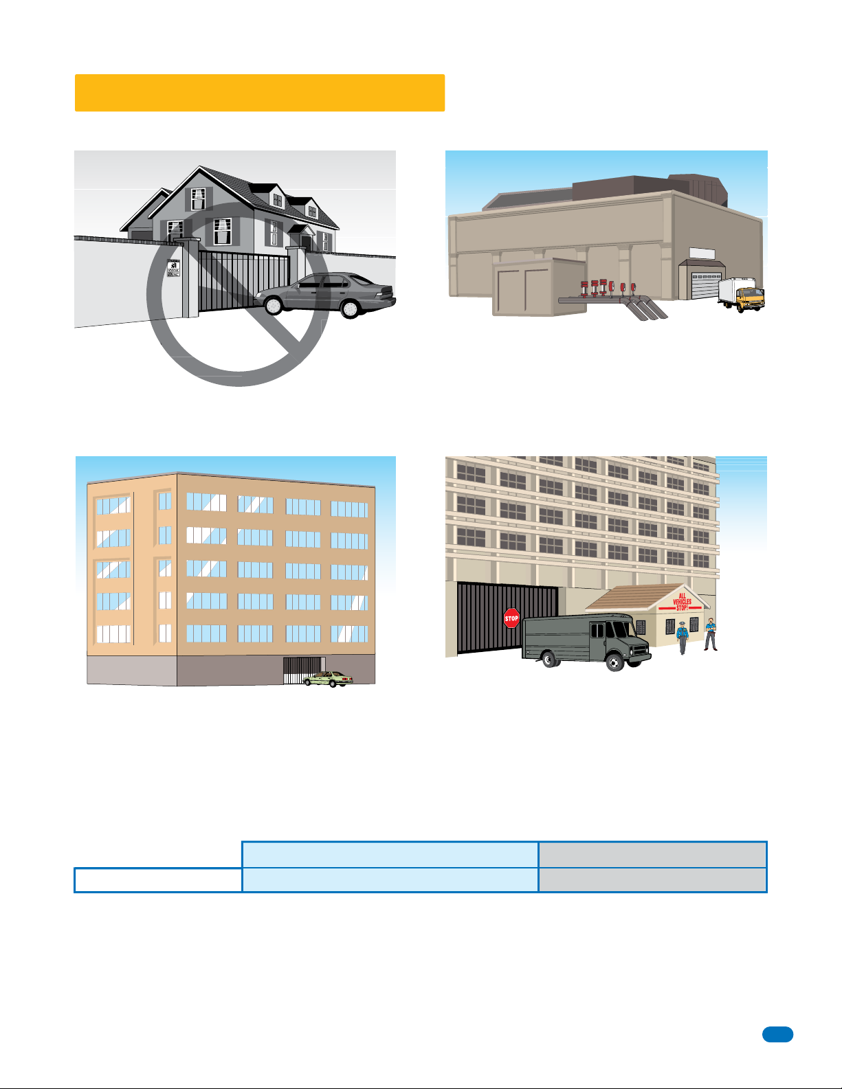
UL325 Entrapment Protection
UL 325 Classifications
Class I - Residential
Vehicular Gate Operator
A vehicular gate operator (or system) intended for use in garages
or parking areas associated with a residence of one‐to four single
families. This does NOT apply to DKS commercial gate operator.
Regency Apartments
Regency Apartments
Industrial Inc
V
Authorized
ehic
l
es O
N
LY
Class III - Industrial/Limited Access
Vehicular Gate/Door Operator
A vehicular gate/door operator (or system) intended for use in an
industrial location or building such as a factory or loading dock
area or other locations not accessible by or intended to service
the general public.
Class II - Commercial/General Access
Vehicular Gate/Door Operator
A vehicular gate/door operator (or system) intended for use in a
commercial location or building such as a multi-family housing
unit (five or more single family units), hotel, garages, retail store,
or other buildings accessible by or servicing the general public.
Gate/Door Operator Category
Horizontal Slide, Vertical Lift, Vertical Pivot Swing, Vertical Barrier (Arm)
Entrapment Protection Types
Type A - Inherent entrapment protection system.
Type B1 - Non-contact sensor (photoelectric sensor or the equivalent).
Type B2 - Contact sensor (edge device or equivalent).
Type C - Inherent force limiting, inherent adjustable clutch or inherent pressure relief device.
Type D - Actuating device requiring constant pressure to maintain opening or closing motion of the gate/door.
* B1 and B2 means of entrapment protection must be MONITORED.
1175-065-H-8-18
Class IV Restricted Access
Vehicular Gate/Door Operator
A vehicular gate/door operator (or system) intended for use in a
guarded industrial location or building such as an airport security
area or other restricted access locations not servicing the general
public, in which unauthorized access is prevented via supervision
by security personnel.
A, B1*, B2* or D A, B1*, B2*, C or D
Vertical Barrier Note: Barrier gate operators (arm)
that is not intended to move toward a rigid object
closer than 16 inches (406 mm) are not required to
be provided with a means of entrapment protection.
5

Glossary
GATE/DOOR - A moving barrier such as a swinging, sliding, raising, lowering, or the like, barrier, that is a stand-alone
passage barrier or is that portion of a wall or fence system that controls entrance and/or egress by persons or vehicles and
completes the perimeter of a defined area.
RESIDENTIAL VEHICULAR GATE OPERATOR – CLASS I - A vehicular gate operator (or system) intended for use in a home
of one-to four single family dwelling, or garage or parking area associated therewith.
COMMERCIAL / GENERAL ACCESS VEHICULAR GATE OPERATOR - CLASS II - A vehicular gate operator (or system)
intended for use in a commercial location or building such as a multi-family housing unit (five or more single family units),
hotels, garages, retail store, or other building servicing the general public.
INDUSTRIAL / LIMITED ACCESS VEHICULAR GATE OPERATOR - CLASS III - A vehicular gate operator (or system)
intended for use in an industrial location or building such as a factory or loading dock area or other locations not intended
to service the general public.
RESTRICTED ACCESS VEHICULAR GATE OPERATOR - CLASS IV - A vehicular gate operator (or system) intended for use in
a guarded industrial location or building such as an airport security area or other restricted access locations not servicing
the general public, in which unauthorized access is prevented via supervision by security personnel.
VEHICULAR BARRIER (ARM) OPERATOR (OR SYSTEM) - An operator (or system) that controls a cantilever type device (or
system), consisting of a mechanical arm or barrier that moves in a vertical arc, intended for vehicular traffic flow at
entrances or exits to areas such as parking garages, lots or toll areas.
VEHICULAR HORIZONTAL SLIDE-GATE OPERATOR (OR SYSTEM) - A vehicular gate operator (or system) that controls a
gate which slides in a horizontal direction that is intended for use for vehicular entrance and exit to a drive, parking lot, or
the like.
VEHICULAR SWING-GATE OPERATOR (OR SYSTEM) - A vehicular gate operator (or system) that controls a gate which
moves in an arc in a horizontal plane that is intended for use for vehicular entrance and exit to a drive, parking lot, or the
like.
SYSTEM - In the context of these requirements, a system refers to a group of interacting devices intended to perform a
common function.
WIRED CONTROL - A control implemented in a form of fixed physical interconnections between the control, the associated
devices, and an operator to perform predetermined functions in response to input signals.
WIRELESS CONTROL - A control implemented in means other than fixed physical interconnections (such as radio waves or
infrared beams) between the control, the associated devices, and an operator to perform predetermined functions in
response to input signals.
INHERENT ENTRAPMENT PROTECTION SYSTEM - A system, examples being a motor current or speed sensing system,
which provides protection against entrapment upon sensing an object and is incorporated as a permanent and integral part
of the operator.
EXTERNAL ENTRAPMENT PROTECTION DEVICE - A device, examples being an edge sensor, a photoelectric sensor, or
similar entrapment protection device, which provides protection against entrapment when activated and is not incorporated
as a permanent part of an operator.
ENTRAPMENT - The condition when an object is caught or held in a position that increases the risk of injury.
6
1175-065-H-8-18
SECTION 1 - INSTALLATION
Prior to beginning the installation of the commercial gate/door operator, we suggest that you become familiar
with the instructions, illustrations, and wiring guide-lines in this manual. This will help insure that your installation is performed in an efficient and professional manner compliant with UL 325 safety and ASTM F2200
construction standards.
The proper installation of the vehicular commercial gate/door operator is an extremely important and integral
part of the overall access control system.
Check all local building ordinances and building codes prior to
installing this operator. Be sure your installation is in compliance with local codes.
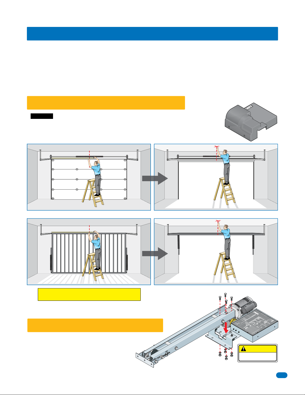
1.1 Determine Location of Operator
IMPORTANT: Make sure the gate/door opens and closes smoothly BEFORE installing operator.
Gate/door should REMAIN in the open position when balancing springs are properly adjusted.
IF the operator is installed less than 8 feet above the floor, then operator’s exposed moving
parts must be covered. DoorKing offers a 1175 cover for protection, Sold separately, P/N 1175-020
C
L
Header
Multi-Panel
1. With the gate/door CLOSED, measure and mark a centerline of the gate.
C
L
Header
2.With the gate/door OPEN, mark a centerline of the gate on the ceiling.
Ceiling
Multi-Panel
Ceiling
1175
Cover
Single Panel
THIS PRODUCT IS FOR INDOOR USE ONLY.
Install in a protected area NOT exposed to weather.
1.2 Attach Rails to Powerhead
Secure rails to powerhead with 4 bolts, nuts and lockwashers.
1175-065-H-8-18
Single Panel
17
/
2
D
6
00
0
5
1
d
1
r
N
a
/
P
o
B
l
r
o
r
o
t
t
n
a
o
er
C
p
O
10
5
0
7
5-
1
0
1
4
l
4
e
l
d
!
e
o
e
d
20
M
o
g
–
M
a
6
t
1
l
o
s
l
V
.
a
s
h
n
n
N
i
o
i
ig
t
O
I
m
c
l
H
r
e
a
e
n
r
n
e
g:
r
n
a
UT
n
T
e
o
i
t
0
r
A
c
i
2
in
r
w
C
r
e
–
r
0
o
s
f
2
o
4
u
t
r
1
d
a
o
w
r
e
9
ls
P
n
e
1
v
)
r
a
r
p
d
s
(
r
e
o
w
in
g
e
8
a
s
.
c
n
P
i
i
n.
1
o
t
8
e
m
v
o
a
r
r
B
d
e
ti
&
v
r
o
i
t
a
D
t
t
i
7
a
7
c
m
o
u
Ter
1
o
r
s
A
o
h
r
B
M
rc
f
i
c
t
o
n
t
i
s
t
i
i
6
i
C
r
w
o
u
y
1
o
s
a
l
,
M
rc
m
d
i
e
1
!
r
r
e
C
5
W
s
e
fo
S
l
h
U
1
t
t
ge
n
f
t
ua
o
e
o
o
n
a
t
4
s
a
n
n
t
N
e
o
1
e
i
l
m
t
R
d
a
e
m
n
o
r
3
e
a
Se
1
p
l
V
e
Oper
n
A
d
*
o
*
2
*
1
m
n
m
o
o
1
.
1
C
m
3
e
m
h
ct
c
g
o
a
t
0
i
t
C
ta
1
w
n
l
s
o
e
,
ct
g
Vo
C
9
a
ta
t
W1
y
l
d
.
w
n
S
a
x
o
e
o
o
l
a
n
s
L
V
3
C
o
M
8
U
Re
t
y
w
a
t
n
sy
2
a
y
o
a
l
o
m
r
u
d
L
er
e
7
0
N
n
D
v
B
i
1
5
e
R
a
*
e
r
t
o
p
2
i
*
c
y
e
e
a
o
*
e
r
t
k
6
D
ad
R
D
c
D
d
R
e
r
e
a
*
**
t
r
i
e
*
rs
*
T
k
m
i
5
e
c
L
e
v
a
n
t
e
r
*
e
a
T
R
p
t
4
G
p
e
O
t
n
e
l
a
e
e
D
r
a
i
i
p
G
3
t
F
r
O
a
C
l
l
P
A
u
2
F
V
n
r
4
s
e
o
2
t
p
1
*
u
ut
n
p
l O
o
n
O
l
l
i
n
I
o
t
u
a
p
l
o
r
t
t
n
.
no
o
d
c
e
s
i
s
n
u
n
o
t
o
s
t
t
i
t
u
t
u
i
b
b
u
-
3
c
3
r
i
a
c
n
e
p
en
h
o
t
h
w
s
w
L
C
T
A
/
U
N
M
al
B
R
m
r
3-
O
o
o
N
t
N
o
t
t
u
l
B
-
o
3
r
t
n
n
o
o
C
p
m
n
o
t
m
o
t
o
S
t
se
C
u
o
l
n
B
e
C
-
p
3
O
)
2
S
N
O
I
c
F
m
n
o
e
d
r
o
m
n
e
L
te
r
o
n
x
*
C
o
to
*
E
i
C
e
n
g
o
ta
l
M
o
V
w
o
L
a
se
r
h
t
e
i
e
v
s
w
r
e
et
n
e
r
o
R
S
i
v
e
t
p
.
e
a
2
t
m
d
m
R
s
e
a
u
j
s
e
m
r
e
T
EC
W
t
u
m
s
S
r
a
/Be
Se
e
e
e
v
g
B
e
/
d
e
1
p
R
E
g
o
t
d
W
e
m
S
s
E
a
S
o
l
n
m
Be
C
e
a
p
e
e
s
B
O
4
o
l
n
C
n
e
3
4
o
p
O
e
m
3
2
n
s
r
m
o
2
e
o
1
m
v
C
se
e
1
m
r
e
R
o
g
ve
C
a
m
t
e
l
e
a
R
g
O
Vo
a
Be
t
e
m
/
l
N
s
a
w
4
e
o
r
e
o
g
V
L
3
B
ve
/
N
w
e
Ed
e
6
O
o
g
R
e
L
p
d
s
12
o
m
!
o
t
l
5
E
a
d
S
n
C
e
e
t
Be
m
p
c
4
T
a
e
e
(
O
e
s
n
e
o
B
.
n
l
3
s
5
o
n
r
C
7
c
e
e
N
1
v
p
2
e
1
N
O
b
l
Re
e
T
1
CO
d
S
m
o
D
a
U
M
e
E
M
r
B
R
.
o
l
d
f
O
e
a
n
78
s
T
N
a
I
nu
r
6
lo
O
N
C
O
M
r
a
e
o
e
h
5
m
t
b
ct
o
e
e
4
T
t
p
e
e
o
S
ch
S
3
o
a
t
N
O
1
nd
D
U
.
L
e
2
M
e
t
Exi
ith
KS
.
ch
va
t
i
w
d
i
D
t
c
n
w
se
o
S
i
l a
t
U
l
i
.
c
t
N
d
n
w
.
o
O
e
u
j
y
N
g)
s
n
a
n
i
U
F
t
o
.
t
)
t
F
c
d
e
g
rel
o
4
O
e
n
n
e
S
i
N
s
ti
l
h
t
t
a
U
F
e
rk
n
t
F
o
m
S
r
e
o
3
l
O
w
o
h
a
N
a
8
.
N
w
t
m
(
r
.
u
e
up
FF
&
o
N
p
F
n
2
r
t
i
.
O
7
F
e
O
u
d
s
m
(N
e
O
w
t
r
O
e
is
s
o
u
e
s
t
r
c
i
p
p
i
U
ch
1
e
e
.
t
r
l
n
g
t
i
I
d
d
e
a
m
o
i
i
w
t
e
n
L
i
m
No
T
s
S
i
e
n
i
p
T
U
p
o
8
se
t
n
FF
e
O
o
o
o
o
&
s
l
l
O
L
l
p
7
o
t
l
u
i
u
-C
F
FN
o
-C
t
N
F
Ex
s
o
i
u
6
t
E
O
s
***
i
A
u
4
P
A
4
N
m
O
.
r
F
s
O
d
e
5
F
rm
e
e
l
T
e
s
O
c
.
T
y
d
U
N
c
n
t
F
O
r
a
o
4
F
o
t
m
N
O
a
r
m
F
e
o
F
c
p
3
O
o
n
e
o
s
p
o
2
**
Set
1
CAUTION
FRAGILE POWERHEAD!
n
o
t
t
e
s
But
e
R
h
tc
r
e
wi
w
S
o
P
h
ig
H
–
N
O
I
d
n
u
UT
o
r
A
G
C
N
E
E
R
G
K
C
A
L
B
E
T
WHI
T
y
O
l
H
n
r
L
O
e
A
C
R
w
T
A
o
U
V
P
E
t
5
N
u
1
x
1
a
np
I
M
n
i
M
x
a
M
s
n
n
i
e
v
M
S
e
R
d
se
t
U
o
N
r
o
ct
te
p
e
e
o
o
D
rs
L
ve
S
e
K
R
D
O
N
NC
t
c
a
t
n
o
C
x
a
y
a
M
l
e
R
n
i
M
c
e
S
r
3
e
2
m
i
0
T
7
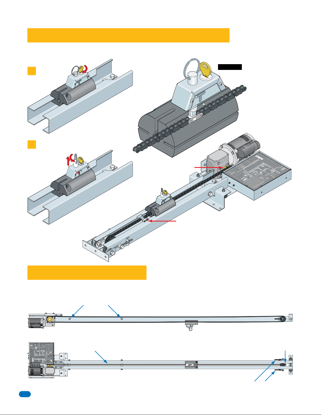
1.3 Manual Release and Chain Connection
Cut wire ties and route chain around gear reducer’s sprocket and through unlocked carriage assembly (To unlock assembly, use key to unlock
release ring, pull ring up and rotate 45° to release spring loaded chain catch). Connect chain together with double master link.
IMPORTANT: The carriage assembly’s
1
Unlock
Pull Up and Turn Ring
2
Sprocket
spring loaded chain catch will only
lock into place in the double
master chain link.
7
1
/
2
D
6
0
0
0
5
1
1
d
r
N
/
P
oa
B
l
r
o
r
o
t
nt
o
C
pera
0
O
1
5
0
-
7
05
11
44
el
l
d
!
0
e
o
e
2
M
od
–
g
M
a
t
n
16
l
s
l
tto
t
Vo
.
a
s
n
o
ti
c
l
a
e
:
ne
r
n
a
ng
er
i
t
r
con
i
20
in
w
r
–
r
o
f
o
4
t
1
d
e
s
v
)
r
s
(
nal
g
e
.
.
n
c
i
i
n
t
8
mi
v
o
a
i
r
e
t
&
v
i
a
D
7
ct
m
Te
s
r
A
h
o
c
nf
s
it
i
i
r
w
y
s
o
la
,
m
e
1
r
r
o
W
e
f
S
h
l
t
a
n
f
u
o
n
o
t
a
n
n
e
io
m
t
d
a
e
n
e
e
er
S
p
p
e
O
d
*
*
*
.
3
11
t
h
c
t
i
0
1
w
s
t
,
9
tac
W1
d
.
n
S
x
e
a
n
s
3
8
o
M
U
t
y
a
t
n
s
2
a
o
m
r
u
d
e
7
0
N
n
v
B
i
1
5
e
a
e
r
2
t
p
io
c
e
e
a
o
d
e
t
k
6
D
a
D
R
c
d
R
*
e
e
a
*
r
it
s
er
T
k
m
5
i
er
c
L
v
e
a
t
e
r
*
a
T
R
pen
t
4
p
e
O
t
n
e
l
a
e
e
D
a
ir
i
p
G
t
3
F
r
O
a
C
l
l
P
A
2
V
Fu
n
r
4
e
o
2
p
t
*
1
u
O
l
O
ul
l
F
mon
o
r
t
t
o
n
.
o
n
d
c
s
e
i
n
s
n
o
u
t
o
t
t
s
t
i
u
u
t
b
i
b
u
3
c
3
ir
a
n
n
e
e
h
w
L
A
l
a
m
r
o
N
l
o
tr
n
n
o
o
C
p
m
n
o
t
o
om
t
S
t
se
u
o
l
B
en
C
-
p
3
O
op
o
m
L
o
*
C
*
e
g
lta
o
V
c
p
ow
o
t
L
s
wh
C
T
/
U
N
e
B
RM
a
-
s
3
O
h
t
er
i
o
N
t
se
w
t
o
r
t
ev
e
n
e
r
o
S
R
v
i
e
t
.
e
a
t
m
d
mp
R
s
e
a
u
j
s
e
e
t
u
m
s
e
B
/
S
t
er
ea
e
u
v
g
B
B
e
-
d
3
e/
R
p
E
g
o
t
d
e
S
s
E
am
o
e
l
m
B
C
en
a
p
e
s
Be
O
o
4
C
l
C
en
n
3
4
p
o
O
m
3
2
n
se
r
m
o
2
e
o
1
m
v
C
e
se
1
m
r
e
R
o
e
g
v
C
a
m
e
lt
e
a
o
R
e
O
V
ag
B
m
/
N
se
w
4
e
olt
r
ea
o
g
e
V
L
B
d
v
/
N
w
e
E
e
6
O
23
o
R
L
p
dg
se
1
o
!
o
E
t
2)
l
5
am
d
S
S
n
C
m
e
e
r
e
t
N
B
m
p
c
4
O
a
Te
I
e
e
O
(
e
s
T
n
o
B
n
l
C
3
se
n
r
E
C
co
e
e
N
p
2
N
ev
O
be
O
R
C
1
ST
m
a
U
e
M
B
8
RED
.
l
e
a
7
d
s
TO
u
I
n
o
n
l
a
N
a
r
C
O
e
m
h
M
t
456
o
ee
h
c
N
a
O
23
e
h
1
).
g
n
tti
g)
e
n
i
S
t
t
l
e
a
S
m
l
r
d
a
o
n
.
N
m
t
a
(
r
u
.
p
o
p
N
F
u
t
N
(
O
F
u
t
s
O
O
i
wer
s
c
o
i
i
p
npu
r
g
l
e
o
n I
ia
L
t
m
i
e
p
op
in
O
n
l
Lo
po
t
ul
i
u
x
E
N
E
s
i
P
O
.
s
d
e
l
se
.
d
yc
U
c
n
r
o
ma
t
m
ra
e
co
op
n
o
s
et
e
n
N
O
I
T
er
s
u
a
o
n
per
o
se
e
r
4
3
1
on
2
1
n
mo
m
c
o
a
t
n
o
C
y
a
l
o
e
C
y
a
el
R
y
r
G
S
.
e
t
t
i
va
i
t
w
c
n
a
o
i
ll
t
i
c
n
u
j
er
m
i
T
i
T
e
s
e
o
l
os
l
C
F
-C
s
o
i
t
u
4
4
m
r
m
e
r
T
e
T
F
ot
F
N
F
F
O
e
p
o
S
1
Bu
i
gh
es
i
m
R
H
r
e
T
AU
C
7
1
6
1
d
e
s
5
1
t
e
1
es
R
rm
a
l
A
m
m
o
C
e
g
a
C
t
l
o
e
g
V
ta
l
o
V
R
y
ow
r
L
D
*
*
*
D
*
**
n
l
a
d
rn
e
r
o
it
n
1
W
S
.
5
7
1
w
ay
l
on
e
r
c
n
i
he
t
k
r
n
o
e
w
h
8
&
.
7
ed
s
U
ot
N
sed.
U
t
o
N
-
F
o
t
F
u
O
A
A
N
F
O
F
O
N
O
4
O
3
2
**
h
20
r
c
w
r
it
P
19
r
d
w
r
w
8
a
S
P
1
o
owe
r
B
rd
o
t
P
t
i
a
u
o
o
c
r
B
r
M
i
o
t
t
C
o
cui
r
M
i
!
C
e
U
g
t
o
a
N
t
l
Vo
h
g
i
H
–
N
w
o
L
s
t
u
p
io
n
I
t
c
ne
e
t
n
x
o
E
C
o
M
2
W
S
1
l
e
d
o
M
r
o
f
ON
e
b
T
S
t
U
i
x
M
KS
.
ch
t
i
D
w
sed
S
U
.
t
N
d
o
O
N
se
U
F
.
t
F
d
o
4
O
N
se
U
F
F
ot
3
O
N
w
F
e
F
n
2
i
O
m
s
e
er
h
t
c
1
t
i
de
w
S
F
8
F
&
O
7
*
6
**
5
d
TIO
n
U
ou
r
A
G
C
EN
E
R
G
CK
A
L
B
TE
I
H
W
T
y
O
H
nl
O
er
AL
C
R
T
A
ow
U
V
P
E
t
5
N
x
pu
11
a
n
I
M
n
i
M
x
a
M
n
ns
i
e
v
M
S
e
R
d
e
s
t
U
o
N
r
o
ct
e
t
p
e
se
oo
D
r
L
e
v
e
KS
R
D
O
N
C
N
ct
a
nt
o
C
x
a
ay
M
l
e
R
n
i
M
c
e
S
3
er
r
2
o
-
m
i
0
ct
T
e
t
p
e
oo
D
L
E
Double Master Chain Link
1.4 Adjust Chain Tension
Do not overtighten chain. Make adjustments equally on both sides of rails. Chain will need final adjustment after operator has been mounted.
Chain will stretch over time and will need to be tightened.
Do not let chain touch steel rail separators.
Approximate chain tension, front rail removed for illustration.
***
NEUTRAL
MinMax Min Max
HOT
115 VAC Only
Input Power
BLACK
WHITE
GREEN
Ground
CAUTION – High Voltage!
Switch
Power
Circuit Board Pwr 20
Model 4405-010 Control Board
Model 1175 Operator
High Voltage!
P/N 1150-006 D 2/17
**
Relay Contact
0-23 Sec
Timer
7&8
Used
3 OFFNot Used.
4 ON Switch MUST be ON for Model 1175.
6 OFFNot Used.
5 OFFNot Used.
4
Not
Sens
Rev
Circuit Board Pwr 19
Motor 17
Motor 18
no user connections.
CAUTION
Terminals 16–20
1
Detector
Detector
Reverse
Loop
Loop
DKS
DKS
MinMax
Exit
OFF Not Used.1
OFFNot Used.2
Switches 7 & 8 work in conjunction with each other and
determine when the relay will activate. See manual.
OFF Auto-Close Timer is OFF.
ONAuto-Close Timer is ON (Normal Setting).3OFF Term 4 is Exit Loop Logic Output.
ON Term 4 is Full Open Input (Normal Setting)
OFF Not Used.2
Set so operator cycles OPEN upon initial power up and
open command.
NC
NO
SW1
SW2
1234
12345678
ON
ON
Connection
Monitored
External
3Open Edge/Beam Reverse
4Close Edge/Beam Reverse
Inputs
Close Beam Reverse (Term 2)
MONITORED CONNECTIONS
ON
1234
Open Beam Stop1
Close Beam Reverse2
1 Open Beam Stop
2 Close Beam Reverse
3 Open Edge/Beam Reverse
4 Close Edge/Beam Reverse
5 Low Voltage Common
6 Low Voltage Common
MUST be connected!
** Loop Out or Full Open 4
Low Voltage Common 12
Low Voltage Common 13
*** Dry Relay Contact 10
*** Dry Relay Contact 11
Low Voltage Common 1
Gate Tracker Busy 8
Gate Tracker Data 7
Partial Open 5
Not Used 14
Not Used 15
Not Used 16
Full Open 2
Not Used 9
* 24 VAC 3
Reverse 6
Common
Set jumper to NORMAL when 3-button is not
used. Set to 3-BUT when a 3-button control
station with a N/C stop circuit is used.
3-But
Close
Open
Stop
* Limited to 250 ma Max.
** Dependant on SW1, switch 3.
*** Operation of the relay is
dependent on SW1, switchs 7 & 8.
See manual for mor information.
3-Button Control
Terminals 14 – 20 are
reserved for internal
operator wiring:
Dept
Fire
Normal
Activating
Device(s)
Receiver
1 2 3
Radio
Chain must be centered between rails.
Return wheel must be centered between rails.
Chain tension adjustment. Adjust equally on both sides of rails.
8
1175-065-H-8-18
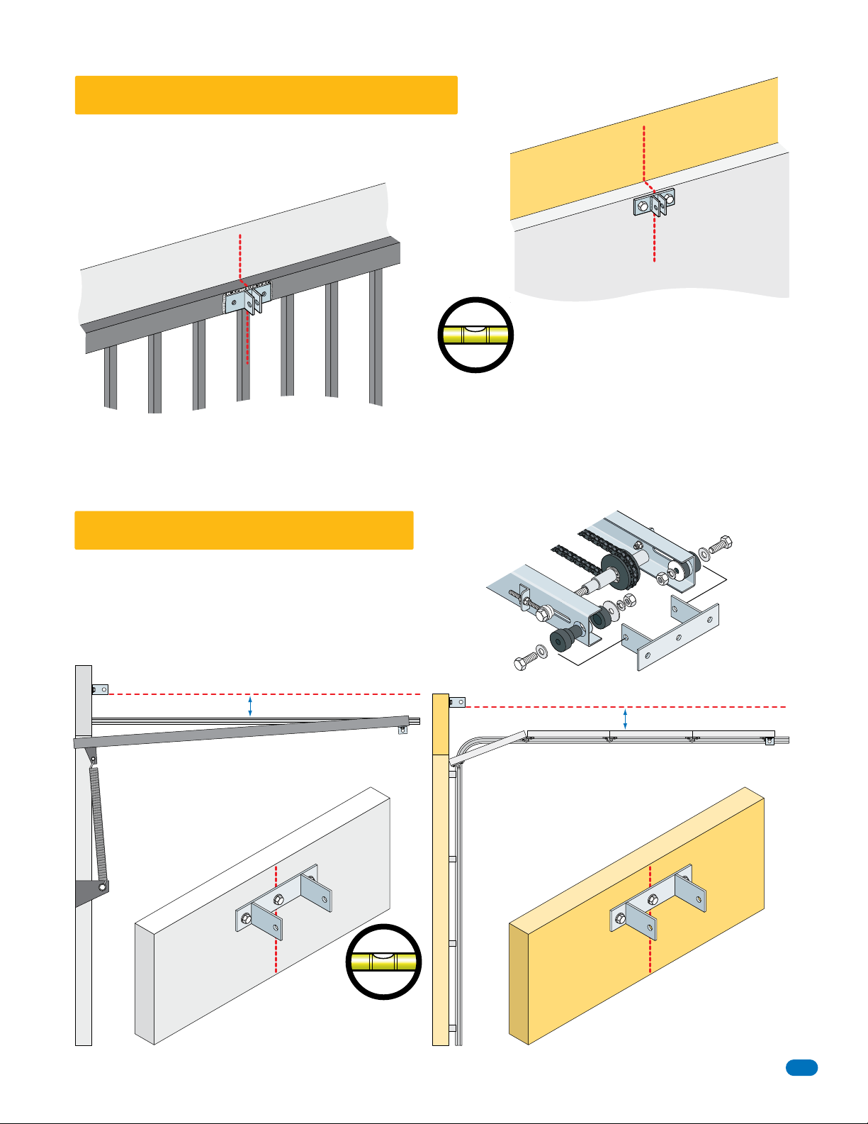
1.5 Attach Gate/Door Bracket
Install the gate/door bracket on the top of the gate/door. Use appropriate hardware,
not included. Bracket must be mounted level and centered on gate/door!
Center Line
Header
Gate/Door Bracket
Center Line
Header
Top Gate/Door Rail
Gate/Door Bracket
Bracket must be mounted level!
Single Panel
Typically welded, completely weld around bracket
1.6 Attach Header Bracket
Header bracket should be mounted on the center line a MINIMUM of 2.5 inches
from highest point of the gate/door in the open position (see below). Use
appropriate hardware, not included. Header bracket must be level and
SECURELY mounted.
Top of Gate/Door
Multi-Panel
Typically bolted
Header Bracket
Assembly
Header
1175-065-H-8-18
Header Bracket
Header
2.5” Minimum
Single Panel
Open
Header
Bracket
Center Line
Install the header bracket with lag
bolts or anchor sleeves.
Bracket must be mounted level!
Header Bracket
Header
Multi-Panel
Header
2.5” Minimum
Open
Header
Bracket
Center Line
9
 Loading...