

Page 1

MARINE
CONTROL UNITS
Elite Control
EN
Installation and Operating Manual ........2
WARNING
Cancer and Reproductive Harm
www.P65Warnings.ca.gov
Elite Control Series
L-5507 | Form No. 341204 20200325 | ©2020 Dometic Corporation
Page 2

Contents Elite Control
Service Center & Dealer Locations
Visit: www.dometic.com
Read these instructions carefully. These instructions
MUST stay with this product.
Contents
1 Explanation of Symbols and Safety
Instructions ............................ 2
1.1 Recognize Safety Information .............2
1.2 Understand Signal Words ................2
1.3 Supplemental Directives .................3
1.4 General Safety Messages ................3
2 Intended Use ........................... 3
3 General Information ..................... 3
3.1 Tools and Materials .....................3
3.2 Display Features .......................4
4 Specifications .......................... 4
4.1 Product Dimensions ....................4
8 Troubleshooting .......................25
9 Disposal .............................. 30
10 Warranty Information ................... 30
1 Explanation of Symbols and Safety Instructions
This manual has safety information and instructions to
help you eliminate or reduce the risk of accidents and
injuries.
1.1 Recognize Safety Information
This is the safety alert symbol. It is used to alert
you to potential physical injury hazards. Obey all
safety messages that follow this symbol to avoid
possible injury or death.
4.2 Cable Length ..........................5
4.3 Available System Inputs ..................5
4.4 Operational Specifications ...............5
5 Wiring Diagrams ........................ 6
6 Installation ............................. 8
6.1 Choosing a Display Panel Location. . . . . . . . .8
6.2 Preparing the Wall ......................8
6.3 Installing an Optional Sensor .............8
6.4 Mounting the Display Panel ..............9
6.5 Testing the Display ......................9
7 Operation .............................. 9
7.1 Understanding the Heating and Cooling
Cycles ..............................10
7.2 Choosing the Control Operation ......... 11
7.3 Using the Control Display Panel ..........13
7.4 Programming the Control ...............14
1.2 Understand Signal Words
A signal word will identify safety messages and property
damage messages, and also will indicate the degree or
level of hazard seriousness.
DANGER!
Indicates a hazardous situation that, if not avoided,
will result in death or serious injury.
WARNING
Indicates a hazardous situation that, if not avoided,
could result in death or serious injury.
CAUTION
Indicates a hazardous situation that, if not avoided,
could result in minor or moderate injury.
NOTICE: Used to address practices not related to
physical injury.
Indicates additional information that is not related
I
to physical injury.
7.5 Navigation Tree .......................24
2
EN
Page 3

Elite Control Intended Use
1.3 Supplemental Directives
To reduce the risk of accidents and injuries, please
observe the following directives before proceeding to
install or operate this appliance:
• Read and follow all safety information and
instructions.
• Read and understand these instructions before
installing and operating this product.
• The installation must comply with all applicable local
or national codes, including the latest edition of the
following standards:
– ANSI/NFPA70, National Electrical Code (NEC)
– American Boat and Yacht Council (ABYC)
1.4 General Safety Messages
WARNING: ELECTRICAL SHOCK, FIRE, AND/
OR EXPLOSION HAZARD. Failure to obey the
following warnings could result in death or
serious injury:
• Use only Dometic replacement parts and
components that are specifically approved for use
with the appliance.
• Avoid improper installation, adjustment, alteration,
service, or maintenance of the appliance. Service
and maintenance must be done by a qualified service
person only.
This manual provides all necessary information for the
proper installation and operation of the Elite Control
display panel. Poor installation and misunderstood
operating parameters will result in unsatisfactory
performance and possible failure. The manufacturer
accepts no liability for damage in the following cases:
• Faulty assembly or connection
• Damage to the product resulting from mechanical
influences and excess voltage
• Alterations to the product without express permission
from the manufacturer
• Use for purposes other than those described in the
operating manual
Dometic Corporation reserves the right to modify
appearances and specifications without notice.
3 General Information
This section provides information on the tooling, parts,
and display features for the Elite Control.
The images used in this document are for reference
I
purposes only. Components and component
locations may vary according to specific product
models. Measurements may vary ±0.38 in. (10 mm).
The Elite Control models have the same features,
installation procedure, and functionality.
• Do not modify this product in any way. Modification
can be extremely hazardous.
• This product should be installed in a controlled,
indoor environment.
2 Intended Use
The Elite Control is a user-friendly 5-volt logic and
micro controller-based unit designed for use with direct
expansion (DX), reverse-cycle air-conditioning systems,
and chilled-water systems (CW). The 5 button display
panel has 33 programmable parameters, automatic and
manual fan speeds, standard and optional sensor inputs,
and fits both Vimar® Idea and Eikon switch bezels.
EN
3.1 Tools and Materials
Dometic recommends that the following tools and
materials be used while installing the appliance:
Recommended Tools
Phillips-head Screwdriver Saw
Safety Glasses
Included Parts Quantity
Screws 4
Elite Control 1
3
Page 4

Specifications Elite Control
Additional Parts
Required for CW Installations (not included)
Water Inlet Temperature Sensor X
Optional Parts
Outside Air Temperature (OAT) Sensor X X
Inside Air Temperature Sensor X X
Auxiliary Electric Heater
Room Temperature/Relative Humidity
Combination Sensor
Seawater Low-Limit Temperature Sensor
Pump Sentry Water Sensor X
1
Additional parts are not included with the standard control package.
2
Available in soware revision C39 and newer.
1
2
2
2
DX CW
X X
X X
X
The maximum length for the display and sensor
I
cables is 75 (22.9 m).
3.2 Display Features
This section explains the function of the buttons and
indicators on the Elite Control display.
Indicator Indicator Name Function
Displays the inside, set
point, outside, and water
temperatures
Indicates the fan speed as
high, medium, or low
Located below the fan speed
indicator, the LED illuminates
when active
Located above the COOL
mode indicator, the LED
illuminates when active.
• The COOL or HEAT mode
LED also lluminates to
indicate which cycle is
active
When only this indicator is lit, it
indicates the COOL-only mode
is active
• When only this indicator is
lit, it indicates the HEATonly mode is active
• When the indicator is
flashing, indicates the
AUXILIARY HEAT mode is
active
AUTO
AUTO
Temperature LED
Display
Fan Speed
Automatic Fan
Mode
Automatic Mode
Cool Mode
Heat Mode
1
1 Elite Control Display
Button Button Name Function
Power
Up
Down
Fan
Mode
Toggles between ON and OFF
mode
Raises the temperature set
point by 1 °F (0.6 °C)
Lowers the temperature set
point by 1 °F (0.6 °C)
Cycles through the different
fan speeds
Selects one of the
four operating modes
(AUTOMATIC, COOL, HEAT,
or DEHUMIDIFICATION) when
the system is in the ON mode
Dehumidification
Mode
Indicates DEHUMIDIFICATION
mode is active
1
If parameter P-13 for the auxiliary heat is enabled, it can also be selected and the
display will show A-H.
4 Specifications
The following table lists the Elite Control dimensions,
cables, system inputs, and operational specifications.
4.1 Product Dimensions
Display Panel Dimensions
for the Idea Bezel
Display Panel Dimensions
for the Eikon Bezel
Cut-Out Dimensions for
the Idea Bezel
Cut-Out Dimensions for
the Eikon Bezel
4.4 in. x 3.0 in.
(112 mm x 76 mm)
4.5 in. x 2.9 in.
(114 mm x 74 mm)
2.3 in. x 3.5 in.
(58 mm x 89 mm)
1.9 in. x 2.8 in.
(48 mm x 71 mm)
4
EN
Page 5

Elite Control Specifications
4.2 Cable Length
Display Cable
Self-Contained
Inside Air Temperature
Sensor (optional)
OAT Sensor (optional) 15.0 (4.6 m) Standard
All custom cable lengths
are supplied in standard
5 (1.5 m) increments
15.0 (4.6 m) Standard
7.0 (2.1 m) Standard
75.0 (22.9 m) Maximum
4.3 Available System Inputs
Water Inlet
Temperature Sensor
(CW Installations Only)
High Refrigerant Pressure 1
1
4.4 Operational Specifications
Set Point Operating
Range
Ambient Temperature
Operating Range
Displayed
Sensor Accuracy ± 2°F @ 77°F (±1°C @ 25°C)
Low Voltage Limit
100–120 V
Low Voltage Limit
200–240 V
Low Voltage Processor
Reset
Universal Line Voltage 100–240 VAC
Frequency 50 Hz or 60 Hz
Fan Output
65 °F to 85 °F (18 °C to 29 °C )
5°F to 150°F (-15°C to 66°C)
95 VAC
195 VAC
50 VAC
6 A @ 115 VAC
6 A @ 230 VAC
Inside Air Temperature
Sensor (optional)
Low Refrigerant Pressure
(optional)
OAT Sensor (optional) 1
Pump Sentry Water
Sensor (optional)
(DX Installations Only)
Room Temperature/
Relative Humidity
Combination Sensor
(optional)
Valve Output 5 A @ 115/230 VAC
1
1
1
1
For CW Only:
Auxiliary Electric
Heater Output
(using compressor
output L1 and L2)
External Triac 26 A
External Q-Relay 30 A Maximum
Pump Output
Compressor Output
Minimum Operating
Temperature
Maximum Ambient
Operating Temperature
Maximum Rh Conditions 99% Non-condensing
30 A Maximum
1/4 HP @ 115 VAC
1/2 HP @ 230 VAC
1 HP @ 115 VAC
2 HP @ 230 VAC
0°F (-18°C)
180°F (82°C)
EN
Power Consumption < 5 W
5
Page 6

Wiring Diagrams Elite Control
5 Wiring Diagrams
WARNING: ELECTRIC SHOCK HAZARD.
Turn power OFF before performing any electrical
installation or maintenance activities. Failure to obey
this warning could result in death or serious injury.
Figure 2 and Figure 3 provide examples of the DX and
CW Wiring for the Elite Control.
Display Jacks (for 8- or 6-pin display and cables)
Inside Temperature Sensor Jack
Not Active
Optional Water-Out Temperature Sensor
Optional Outside Air Temperature Sensor
Low-Pressure
Switch
Optional
DC Blower
High-Pressure
Switch
0-10 VDC
GND
JP5 Temperature Sensor Selection Jumper
JP2 Low Pressure Switch Jumper
Gate Terminals to
Auxiliary Heat Relay
Pump or
Pump Relay Panel
Reversing Valve or
Electric Heat
2 DX Wiring Diagram
Comp L1
Pump L1
Pump L2
Compressor
Fan Run
Capacitor
Comp L2
Fan
Run Capacitor
Ground
L2
Fan L1
L2
L1
2
5
AC
1
6
Start Relay
4
L1
Start
Capacitor
6
EN
Page 7

Elite Control Wiring Diagrams
Optional
DC Blower
JP1 System Selection Jumper
JP5 Temperature Sensor Selection Jumper
0-10 VDC
GND
SMX DISPLAYS ONLY
COM
For Humidistat
COM
For Changeover Switch
L2
L1
L2
Display Jacks (for 8- or 6-pin display and cables)
Inside Temperature Sensor Jack
Required Water Inlet Temperature Sensor
Optional Water-Out Temperature Sensor
Optional Outside Air Temperature Sensor
Ground
L1
AC
Water Valve
3 CW Wiring Diagram
L2
Electric Heat Strip
L1
Fan Run
Capacitor
Fan
L2
L1
EN
7
Page 8

Installation Elite Control
6 Installation
WARNING: ELECTRIC SHOCK HAZARD.
Turn power OFF before performing any electrical
installation or maintenance activities. Failure to
obey this warning could result in death or serious
injury.
NOTICE: Failure to obey the following notices could
result in damage to the product:
• Do not locate the display panel in direct sunlight,
near any heat-producing appliances, or in a bulkhead
where temperatures radiating from behind the panel
may affect performance.
• Do not mount the display in the supply-air stream or
above or below a supply-air or return-air grille.
• Do not mount the display behind a door, in a corner,
under a stairwell, or any place where there is no freely
circulating air.
• Do not staple sensor cables during installation.
• Do not use a screw gun and do not over-tighten the
screws when mounting the display. Either method
may damage the display.
The system’s display built-in temperature sensor
I
is located in the control’s display panel. An
optional inside air temperature sensor is required if
installing the display panel in a cabinet, enclosed
space, or any area where the accurate sensing of
the room temperature would be impaired.
6.2 Preparing the Wall
Cut the cabin wall to fit the display panel, according to
the bezel being used.
w
q
4 Idea Bezel Cutout Dimensions
2.3 in. (58 mm)
q
3.8 in. (97 mm)
w
w
q
r
2.4 in. (61 mm)
e
3.5 in. (89 mm)
r
e
e
This section describes how to install an Elite Control.
6.1 Choosing a Display Panel Location
Place the display panel in an area that meets the
following location criteria:
• Mounted on an inside wall of the cabin, away from
direct sunlight
• Sets slightly higher than mid-height of the cabin
• Located in an area of freely circulating air
• Placed a maximum distance of 15 (4.6 m) from the
air conditioner
8
r
5 Eikon Bezel Cutout Dimensions
1.9 in. (48 mm)
q
3.8 in. (97 mm)
w
2.2 in. (56 mm)
e
2.8 in. (71 mm)
r
6.3 Installing an Optional Sensor
1. Mount the optional sensor according to the
installation instructions included with the sensor.
2. Plug the sensor cable into the appropriate sensor
jack on the upper side of the control board. Refer to
“Wiring Diagrams” on page 6 for details on the
sensor jack locations.
EN
Page 9
Elite Control Operation
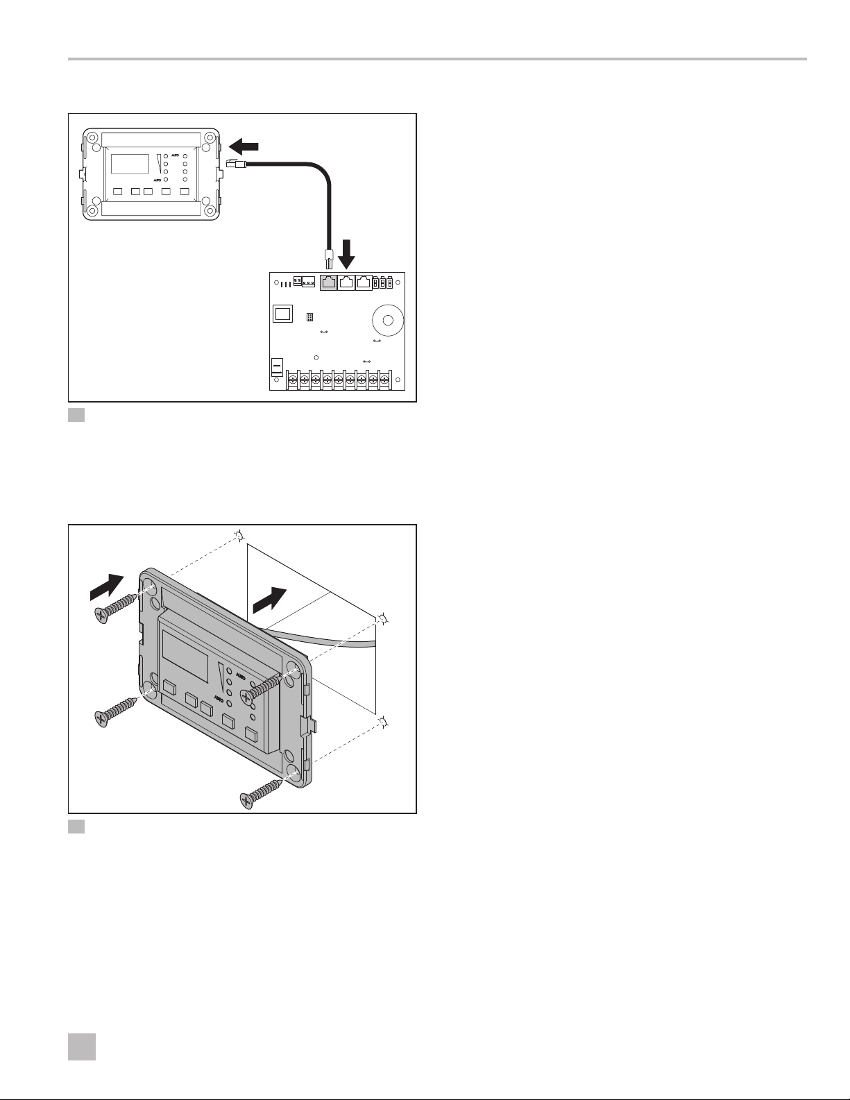
6.4 Mounting the Display Panel
PRESS SWT
MA DISPLAY CA DISPLAY
DC
HP LP
RES
SEL
LPF EMBLE
CW EMBLE
JP3
JP1 JP2
JP5
JP4
AUX HEAT
GATE
TRM-1
COMPL2FANL2PUMP
6 Plugging in the Display Cable
1. Plug the display cable 8-pin connector into the
upper-right jack on the circuit board.
2. Insert the other end of the display cable into the
display jack on the back of the display panel.
INSIDE H20INH20
J2 J3
J1
PSNB
JP6
VSNB
JP8
COMP
VALVEL1FAN
PUMP
L1L2
L2
L1
L1
P4 P5 P6
6.5 Testing the Display
NOTICE: For DX units only: do not turn the circuit
breaker or power supplied to the unit OFF and then
immediately turn it back ON. Allow at least five minutes
for the refrigerant pressure to equalize. Failure to obey
this notice could result in damage to the air conditioning
unit.
1. Open the seawater-intake ball valve (seacock).
OAT
OUT
L1
2. Turn the display OFF. Wait a minimum of five minutes.
3. Turn the air conditioner circuit breaker ON.
If the seawater pump is on a separate circuit
I
breaker, be sure to turn it ON.
4. Turn the display ON.
5. Press the Fan button.
6. Verify that the fan is running and that a steady airflow
is coming out of the supply-air grille.
7. Select a temperature set point lower than the current
cabin temperature.
8. Verify that a steady, solid stream of water is coming
out from the overboard discharge.
q
e
r
7 Securing the Display
Cutout
q
Display Panel
w
3. Use the four screws provided to secure the display
panel to the bulkhead. Do not use a screw gun or
overtighten the screws.
4. Snap the bezel onto the display panel frame.
w
e
r
Bezel
Screw
9. Verify that a steady airflow is continues to flow out of
the supply-air grille.
If the unit is not functioning as expected, refer to
I
“Troubleshooting” on page 25.
7 Operation
NOTICE: If the unit is cool-only, change parameter P-33
to CL, then select AUTO mode. Do not set the unit to
AUTOMATIC mode before changing parameter P-33 to
CL. Cool-only units do not heat unless equipped with
auxiliary heating. Failure to obey this notice will cause
the unit to cool in both modes. Refer to “Selecting a
Parameter” on page 16.
When used with optional auxiliary electric heater,
I
the fan remains ON for four minutes aer the heater
cycles OFF, even if the fan is set to cycled operation.
The images in this section show the Elite Control
I
display, unless otherwise indicated.
This section describes the cycle, programming, and
functions for the Elite Control.
EN
9
Page 10

Operation Elite Control
7.1 Understanding the Heating and Cooling Cycles
The heating and cooling cycles operate differently
depending on the system installed. This section
describes the possible cycles.
7.1.1 Normal Heating or Cooling Cycle
In AUTOMATIC mode, heating and cooling are supplied
as required to meet the cabin temperature set point.
• The system starts a cooling cycle once the cabin
temperature exceeds the temperature set point by
2°F (1°C) and starts a heating cycle once the cabin
temperature falls below the temperature set point by
2°F (1°C). The system continues the cycle until the
cabin temperature equals the set point.
• During a cycle, the cabin temperature must drop
below the set point by at least 4°F (2°C) before the
system switches from cooling to heating or exceed
the set point by at least 4°F (2°C) before the system
switches from heating to cooling. This behavior
prevents small temperature overshoots from causing
the system to switch between heating and cooling
when it is not necessary.
COOL mode supplies cooling only and HEAT mode
supplies heating only.
• The cabin temperature for either mode is maintained
within 2°F (1°C) of the set point by default.
• When the heating or cooling set point is satisfied,
the compressor cycles OFF and the fan returns to low
speed.
To view the current water temperature, press and hold
Power and Down. Refer to “Using the Control Display
Panel” on page 13. The fan remains on low speed
until the adequate water temperature is available.
To provide heat when the required water
I
temperature is not available, install the optional
auxiliary electric heater and program parameter
P-13. Refer to “Programming the Control” on page
14.
7.1.3 Air and Water Temperature
Differential (CW Systems Only)
The electric heater and the chilled-water heat can affect
the CW system.
The optional auxiliary electric heater overlaps with the
chilled-water heat by 22 °F (12° C). The heater turns on
when required and remains on until the chilled-water
temperature exceeds the ambient air temperature by
22 °F (12° C) or until the room temperature is satisfied.
During very cold conditions, the auxiliary electric heat
overlaps the chilled-water heat to supplement heating.
Water Temperature Differential
in °F
Default is 15 °F (-9°C)
22°F (-6°C) Open Off
15°F (-9°C) Open On
7 to 15 °F (-14 to 9 °C) Hysteresis On
7°F (-14°C) Close On
7 to 0 °F (-14 to -18 °C) Close On
0°F (-18°C) Close Off
Valve
Auxiliary
Heater
In Manual Fan Mode, the fan speed remains constant.
7.1.2 Chilled-Water System Operation
(CW Systems Only)
In CW systems, the water valve does not open unless the
water temperature is adequate to heat or cool the cabin.
The adequate heating or cooling water temperature is
defined by the water temperature differential setting in
the control parameters. Refer to “Selecting a Parameter”
on page 16.
10
0 to -7 °F (-18 to -22°C) Close Off
-7°F (-22°C) Close Off
-7 to -15 °F (-22 to -26°C) Hysteresis Off
-15°F (-26°C) Open Off
EN
Page 11

Elite Control Operation
7.1.4 Reversing-Valve Operation (DX
Systems Only)
COOL mode or HEAT mode is determined by the
position of the reversing valve. The reversing valve is
programmed to automatically toggle in these situations:
• When the system is running and an opposite cycle is
needed to maintain the temperature, the reversing
valve will toggle to the opposite position to initiate
the opposite cycle and reduce the starting surge of
the compressor.
• When a cooling or heating cycle is initiated aer the
system has been OFF for less than five minutes.
• When a cycle is interrupted by changing the display
mode to OFF or changing the set point from the
display panel.
To reduce reversing-valve noise, unnecessary valve
toggling is limited by default. Program the minimum
compressor staging delay (parameter P-3) to five
minutes or greater, to eliminate valve toggling. Refer to
“Programming the Control” on page 14.
When the system is powered up, a power-on-reset
I
always initiates a valve toggle.
and by periodic HEAT mode cycles with the fan turned off.
The de-icing cycle algorithm initiates periodic
compressor shutdowns every 10 minutes if the inside
temperature is at or below 69 °F (20 °C). The lower the
temperature, the longer the compressor shutdown will
last. In addition, the de-icing cycle algorithm will perform
brief reverse cycle runs (with the fan purposely turned
off) if the cooling cycle runs for 40 minutes without any
cooling progress or if the cooling cycle runs for more
than 60 minutes, regardless of cooling progress.
The parameter setting for the de-icing feature
depends on whether you are using the
optional inside air temperature sensor or the
display built-in temperature sensor. Installation of an
optional inside air temperature sensor (located in the
return air path) greatly increases the effectiveness of the
de-icing feature, and this option should be considered
whenever the display sensor cannot read the room
temperature accurately.
For additional details on parameter settings and
navigation options, refer to “Selecting a Parameter” on
page 16 and “Navigation Tree” on page 24.
7.2 Choosing the Control Operation
7.1.5 De-icing Cycle (DX Systems Only)
DX systems have a de-icing cycle option to prevent ice
buildup on the evaporator coil during extended periods
of cooling operation. Installation variables, such as
grille sizes, length of ducting, insulation, and ambient
temperatures, determine the runtime required to achieve
the set point.
Factors that substantially increase the runtime include
operating the system with hatches and doors open and
programming an unrealistic set point (e.g. 65 °F/18 °C).
Such situations can cause the evaporator to form ice on
warm humid days.
De-icing is accomplished by closely monitoring the room
air temperature in 10-minute intervals during a cooling
cycle. Depending on the parameter value and the change
in room temperature during these monitoring intervals,
the control performs various actions to prevent ice from
forming or to melt ice that has already formed. This is
accomplished by short compressor shutdown periods
combined with a one-speed increase in the fan speed,
The four Mode indicators represent the different modes
of the control: COOL, DEHUMIDIFICATION, HEAT, and
AUXILIARY HEAT. Refer to “Using the Control Display
Panel” on page 13.
8 Choosing the Control Operation
1. Press and release the Mode button to select a
mode. Refer to “Available Modes and Options for
Operation” on page 12.
EN
11
Page 12

Operation Elite Control
– Display LEDs illuminate to indicate the selected
mode.
– To indicate an OFF state, all the display LEDs turn off.
– When the display is making a call for heating,
– The display locks into the last mode selected aer
five seconds of inactivity, then displays the room
temperature. The selected mode LED remains lit.
– Aer 3 seconds of inactivity, the display shows the
room temperature and enters the IDLE state.
2. Press the Power button to wake up the control from
the OFF state.
Available Modes and Options for Operation
Icon Description/Mode Function
The AUTOMATIC mode LED illuminates, together with the HEAT or COOL mode LED, when the
AUTOMATIC
AUTO
AUTOMATIC with
Auxiliary Heat
COOL
HEAT
DEHUMIDIFICATION
system is in AUTOMATIC mode, switching to cooling or heating as required to satisfy the temperature
set-point. When AUTOMATIC mode is selected, the system provides both heating and cooling, as
required.
The AUTOMATIC mode LED flashes when the optional auxiliary electric heater is in operation.
• The control’s display will indicate AAH.
• The HEAT mode or COOL mode LED also illuminates to indicate whether the unit is cooling or
heating.
• In CW systems, these LEDs indicate the water-valve operating status (open or closed). No watervalve status is indicated when the system is in manual HEAT or COOL modes.
The COOL mode LED illuminates when the COOL mode is selected or when the unit is in an
AUTOMATIC mode cooling cycle. Only the cooling system operates. If the ambient temperature drops
below the set point, the system will not automatically switch to the HEAT mode.
The HEAT mode LED illuminates when the HEAT mode is selected or when the unit is in an
AUTOMATIC mode heating cycle. Only the heating system operates. If the ambient temperature rises
above the set point, the system will not automatically switch to the COOL mode. When the unit is
heating with auxiliary heat, the HEAT mode LED will flash to differentiate from reverse cycle heating.
The DEHUMIDIFICATION mode LED illuminates when the DEHUMIDIFICATION mode is selected.
This mode controls humidity during periods when the vessel is unoccupied and prevents the cabin
temperature from dropping below the minimum default temperature setting.
During humidity control:
• The fan circulates air for 30 minutes.
• Air temperature is sampled and recorded.
• Aer 30 minutes, a cooling cycle starts and continues until the temperature is lowered 2°F (1°C) or
until the cooling cycle runs a maximum of one hour.
• Four hours aer the temperature is satisfied or the cooling cycle times out, the cycle repeats.
For temperature control:
• Aer the 30-minute fan circulation, if the sampled temperature is at or above the factory default
setting 50°F (10°C), a cooling cycle begins and runs for humidity control.
• If the temperature is below 50°F (10°C), a heating cycle begins. The heating cycle continues until
the temperature reaches 50°F (10°C) or until the heating cycle runs a maximum of one hour.
• Four hours aer the temperature is satisfied or the cooling/heating cycle times out, the cycle
repeats, each time determining whether cooling or heating is required.
cooling, auxiliary heat, or humidity, the appropriate
Mode indicator illuminates (and flashes for auxiliary
heat).
12
ON
For DX systems only: the DEHUMIDIFICATION mode heat cycle will not run when the ambient
I
temperature is below 40°F (4°C). This protects the condenser coil from freezing. Systems
configured with electric heat will run the DEHUMIDIFICATION mode heat cycle regardless of
the cabin temperature.
All control outputs are on and the display indicates the current state of operation. The display shows
the cabin temperature. All parameters operate as set.
EN
Page 13

Elite Control Operation
Available Fan Modes and Options for Operation
Press and release the Fan button to select a fan mode.
Refer to “Available Modes and Options for Operation”
– Display LEDs illuminate to indicate the selected
mode.
on page 12.
Indicator Description/Mode Function
The automatic fan mode balances the most efficient temperature control with a slower, quieter fan
speed. This mode selects the fan speed automatically based on the temperature differential.
To select automatic fan mode, press and release the Fan button until the AUTO LED below the Manual
Fan indicator illuminates on the display.
• The auto fan speeds are automatic based on default and programmed values. Program menu
parameter settings P-1, P-2, and P-32 determine the maximum, minimum, and middle fan speed
AUTO Automatic Fan
Manual Fan
Fan-Only
CYN / CON
Cycled / Continuous
Fan
settings.
• Fan speed decreases as the temperature set-point is approached in COOL mode and operates at
low speed when the set point is reached.
• The automatic fan speed operation can be reversed for HEAT mode when parameter P-12 is set to
rEF. Refer to “Programming the Control” on page 14.
Refer to “Selecting a Parameter” on page 16. Once high and low fan speed limits are set, the
I
unit automatically readjusts the remaining fan speeds in both automatic and manual fan modes.
The manual fan LED illuminates to indicate the current fan speed. There are three manual fan speeds
available. The number of bars illuminate (1=low, 2=medium, and 3=high) on the display when
selected.
• Press and release the Fan button to advance from automatic to manual fan operation.
• Press and release the Fan button to cycle through the manual fan speeds, from low to high.
• Press and release the Fan button to return to automatic fan operation.
Use fan-only to operate the fan for air circulation when no cooling or heating is desired.
• From the OFF mode, press and release the Fan button to select a desired fan speed.
Turning the control ON reverts the fan to the AUTOMATIC mode or the last selected manual fan
I
setting.
The fan can be set to run continuously whenever the system is turned ON, or it can be set to cycle ON
and OFF in conjunction with the cooling or heating cycles.
• Press and hold the Fan button for five seconds.
– CYC displays when the operational setting is set to cycled. When used with an optional
auxiliary electric heater, the fan remains on for 4 minutes aer the heater cycles off.
– CON displays when the operational setting is set to continuous.
7.3 Using the Control Display Panel
The following table details the button combinations to
use to achieve different functions on the control.
Button Combinations Button Names Function
Fan, Up, & Down
& &
EN
Lock and unlock the keypad:
Press simultaneously to toggle the keypad lock on or off. The display shows LC
when the keypad is locked, or UL when the keypad is unlocked.
For soware revisions B28 and newer, view some indicators even if the keypad
is locked:
• (CW only) To view the chilled-water-inlet temperature, simultaneously press
the Power & Up buttons
• (DX only) To view the pump sentry water temperature, simultaneously press
the Power & Up buttons (P-8 must be on)
• (DX only) To view the sea water low-limit temperature, simultaneously press
the Power & Down buttons
13
Page 14

Operation Elite Control
Button Combinations Button Names Function
&
&
&
&
&
, ,
& ,
Up & Down
Power & Down
Power & Up
Mode & Up
Up & Down
AC Power set to Off &
then Mode, Power, or
Down
Power & Mode
Display the outdoor temperature: Press simultaneously and hold.
The display shows the outdoor temperature reading while this combination is
held.
(CW only)
Display the chilled-water-inlet temperature: Press simultaneously and hold.
(DX only)
Display the pump sentry water temperature: Press simultaneously and hold.
Enter the programming menu:
• With the control in OFF mode, press the following buttons in this order:
Mode, Up, Down, and Mode. P1 appears on the display. The display will
alternate between the parameter number and the current setting.
• Navigate using the Mode and Fan buttons and adjust a parameter setting
using the Up and Down buttons.
• Press the Power button once to save changes and return to OFF mode.
Set new default parameters:
While in PROGRAM mode, press simultaneously and hold for three seconds.
Disconnect the AC power, then press the specified button immediately aer
reconnecting the AC power and while all LEDs are illuminated during power-on
reset for the following information.
• View the fault history log: press the MODE button.
• Exit the fault history log: press the POWER or MODE button once, and wait
30 seconds.
• Clear the fault history log: press simultaneously the POWER and DOWN
buttons while viewing the fault history log.
• Display the compressor run-time hour meter: press the DOWN button. This
meter displays hours of compressor usage, with a maximum capture time of
65,536 hours.
• Enter the self-test program: press the POWER button. Use the self-test
program to diagnose problems and test the air conditioning system.
Restore factory default settings:
• Turn off the air conditioning unit.
• Press simultaneously and hold the POWER and MODE buttons.
• Turn the air conditioning unit on, and then release the buttons when the
display reads IP.
7.4 Programming the Control
If your AC has a Shaded-Pole (SP) fan motor
I
instead of a Split-Capacitor (SC) High-Velocity
(HV) fan motor, you must change the parameter
P-14 setting to shaded-pole (SP) before operating
the equipment. SP units are recognizable by an
overhanging blower motor. Only reprogram the
fan motor type parameter if you do not have an HV
blower.
14
For CW Only: Standard air handlers come
I
equipped with chilled-water bypass valves.
However, for no-valve air handlers, the fan must be
set to cycle on demand (CYC).
For DX Only: If your air conditioning unit is cool-
I
only (if it does not have a reversing valve), you
must change the parameter P-33 setting from heat
pump (HP) to cool only (CL). Refer to “Selecting a
Parameter” on page 16.
– You must change the parameter before setting the
Automatic mode for a cool-only unit.
EN
Page 15

Elite Control Operation
– Once this parameter is set, the only allowable
modes are OFF, COOL, AUXILIARY HEAT, and
DEHUMIDIFICATION.
– If the AUTOMATIC mode is selected and the
thermostat calls for heat, the compressor will
run. Since there is no reversing valve, the air
conditioning unit will supply cool air when
heating is desired. Cool-only units do not heat
unless equipped with auxiliary heating.
Parameter settings are used to program and fine-tune
the system for the most efficient operation within an
installation and to adjust operating parameters for your
particular needs. Aer new values are entered and
memorized, the factory defaults are overwritten and the
new parameters become the default values.
Should the Elite lose power, the operating parameters
are retained. When power is restored, the control
resumes operating as last programmed.
The control has factory default values stored in
permanent memory (memorized factory default settings)
that can be recalled if you have any programming
difficulties. You can restore the original factory default
parameters manually. Refer to “Selecting a Parameter”
on page 16 for a summary of the parameters, the
permitted values, and original factory default settings.
7.4.1 Entering Programming Mode
1. While the control is in the OFF mode, press the
following buttons in this order: Mode, Up, Down,
and Mode to enter the programming menu. P-1
appears on the display. The display will alternate
between the parameter number and the current
setting.
2. Use the Mode and Fan buttons to navigate to
different parameters (P-1, P-2, P-3, etc.).
3. Press the Up and Down buttons to adjust a
parameter setting.
4. Press the Power button once to save any changes
and to return to OFF mode. If no button is pressed for
50 seconds, the system will exit the Program mode
and return to OFF mode automatically.
EN
15
Page 16

Operation Elite Control
7.4.2 Selecting a Parameter
The following table describes the parameters available
for the Elite Control.
Parameter Name DX CW Factory Default Parameter Range
x x 95 51–95
P-1 High Fan Limit
Select a higher number to increase the fan speed, a lower number to decrease the fan speed.
The 35-95 parameter range setting is applicable to soware revision #B24 and newer.
I
P-2 Low Fan Limit
P-3
P-4
P-5 Failsafe Level
P-6 Low Voltage Monitor
Compressor Staging
Time Delay
Inside Air Temperature
Sensor Calibration
x x 50 30–50
Select a higher number to increase the fan speed, a lower number to decrease the fan speed.
x 15 5–135 seconds
Use for installations where more than one system operates from the same power source. Different
staging delays allow compressors to start at different times when the power is interrupted. Stage the
units at least five seconds apart.
x x Ambient Temperature Ambient Temperature ±10°F (6°C)
Calibrate the sensor to display the correct room temperature reading.
The setting increments are in °F even when the control is set to display °C.
0 = Minimal Protection
x 3
1Part of the functionality of this setting is only applicable to soware revision #C40 and newer.
I
2The setting is applicable to soware revision #C39 and older.
Refer to “Fail Safe Levels” on page 23.
x OFF OFF, 95 VAC/195 VAC
Set the built-in voltmeter circuit that monitors the AC input voltage prior to each cooling or heating
cycle when set to 95 VAC or 195 VAC.
• For 100–120 VAC input power, set to OFF or 95.
• For 208–240 VAC input power, set to OFF or 195.
The setting is applicable to soware revision #A15 and newer.
1 = Continuous No Display
2 = Continuous With Display
3 = Four Failures, Reset Required
1
2
2
I
16
EN
Page 17

Elite Control Operation
Parameter Name DX CW Factory Default Parameter Range
OFF
1 = ON with 5°F (3°C) Display Sensor Differential
2 = ON with 7°F (4°C) Display Sensor Differential
OFF
ON = Select 100°F to 150°F
(38°C and 66°C)
P-7 De-icing Cycle
P-8 Optional Pump Sentry
x OFF
Select the parameter setting for the de-icing feature depending on whether you are using the
display built-in temperature sensor or the optional inside air temperature sensor.
• If using an optional inside air temperature sensor., set this parameter to 1 to turn the de-icing feature
ON, or to OFF to disable.
• If using the display built-in temperature sensor, choose one of the two selectable behavior modes:
– 1: assumes the display built-in temperature sensor may be reading the room temperature as
much as 5°F (3°C) greater than the actual evaporator temperature (standard).
– 2: for more extreme installations - assumes the display built-in temperature sensor may be
reading the room temperature as much as 7°F (4°C) greater than the actual evaporator
temperature.
• The setting of 2 should only be used if a setting of 1 does not prevent evaporator ice from forming.
The following applies to soware revision #A13 and older.
I
De-icing is accomplished by switching the reversing valve to HEAT mode while the system
is cooling. The valve remains energized for the programmed cycle time. The cycle is
programmable to OFF or to a period of one, two,or three minutes.
The following applies to soware revision #A15 and newer.
I
De-icing is accomplished by closely monitoring the room air temperature in 10-minute intervals
during a cooling cycle. Depending on the parameter value and the change in room temperature
during these monitoring intervals, the control performs various actions to prevent ice from
forming or to melt ice that has already formed. These actions include short compressor shutdown
periods combined with a one-speed increase in fan speed and by periodic HEAT mode cycles
with the fan turned off.
x OFF
Set this parameter setting when the optional pump sentry water sensor is installed to monitor the
condenser coil temperature and to shut down the pump and compressor when the coil temperature
rises above the programmed value. This sensor is plugged into the H2O OUT sensor jack on the
control board.
P-9
P-10
P-11
P-12
Display Brightness
Control
Fahrenheit or Celsius
Selection
Cycle Pump with
Compressor
Reverse Automatic Fan
Speeds During Heating
Program a temperature between 100°F and 150°F (38°C and 66°C), depending on seawater
temperature and the system type. Refer to the sensor installation instructions for detail. The setting
increments are in °F even when the control is set to display °C.
x x 4 (Dimmest)–18 (Brightest)
Set this parameter setting between 4 and 18.
A dark cabin requires a setting of 4. A very bright cabin requires a setting of 12–18.
F = Fahrenheit Displayed
x x F
Select °C for Celsius. (Celsius readings are displayed in tenths, for example 22.2°). The default setting is °F.
x CYC
Select cycled or continuous pump operation:
• CYC: increases the pump life and conserves electricity by cycling ON and OFF with the compressor.
• Con: programs the pump to operate continuously whenever the system is on.
x x rEF
Reverse the automatic fan speeds during HEAT mode to improve heat output in cooler climates.
• When set to rEF, the fan speeds up as the set point is approached. The fan switches to low speed
when the set point is satisfied and the water valve or compressor cycles OFF.
• When set to nOr, the fan operates the same as during cooling, which represents normal fan operation.
C = Celsius Displayed
A = Automatic Selection Based on Voltage
50 Hz = Celsius
60 Hz = Fahrenheit
CYC = Cycle with Compressor
Con = Continuous Pump
nOr = Normal Fan Operation
rEF = Reversed Fan in HEAT Mode
EN
17
Page 18

Operation Elite Control
Parameter Name DX CW Factory Default Parameter Range
nOr = Disable
A-H = Auxiliary Electric Heat
SC = Split Capacitor Fan Motor
SP = Shaded Pole Fan Motor
rST = Reset Defaults
nOr = Normal
OPn = Valve Forced Open
nOr = Normal Operation
P-13 Auxiliary Heat Enable
P-14 Fan Motor Selection
P-15
P-16
P-17
Restore Factory Default
Settings
Hydronic Water Valve
Forced Open
Water Temperature
Differential
x x nOr
Enable the operation of an optional auxiliary electric heater that if installed, can heat an individual cabin
when the chiller system is in cooling mode. Refer to “Wiring Diagrams” on page 6.
The following is applicable to soware revision #A13 and older.
I
When this parameter is programmed for auxiliary electric heat, only the electric-heat relay located
toward the middle of the circuit board is energized during a heating cycle.
The following is applicable to soware revision #A15 - #C30.
I
When programmed for auxiliary electric heat, both the electric-heater relay and the valve relay
are energized. This change supports newer circuit board revisions without the electric-heat
relay. Please consult with Dometic Customer Service or with an authorized service technician for
assistance.
– For CW systems: Circuit boards that do not have electric-heat relays require a display with
soware revision A15 or newer to properly energize the compressor relay. Also, when using
this configuration, the electric heater L-1 connection must be connected to the COMP L-1
terminal on the AH-Passport I/O or U-board.
– For DX systems: Circuit boards that do not have electric-heat relays require a display with
soware revision A15 or newer to properly energize the valve relay. Also, since the valve-relay
output only supports a maximum of 15 amps at 115VAC or 10 amps at 230 VAC (PPIO circuit
boards revision F and newer) of resistive load, when installing an optional electric heater that
exceeds this load, it is necessary to install an additional contactor that is rated to handle the
full load of the electric heater.”
x x SC
Set to SC for AC switch high-velocity blowers. Set to SP if your unit has a Shaded Pole fan motor. Refer
to “Programming the Control” on page 14.
x x nOr
To reset all programming parameters, set this parameter to rST. This restores all programmable
parameters to the factory default values.
x nOr
Open the water valve to bleed air from the system.
• OPn: forces the valve open for four hours while the control is turned OFF. If the control is turned ON
or if AC power is interrupted during this four-hour period, the valve override is canceled.
• nOr: returns the valve to normal operation.
x 15°F (8°C) 5°F to 25°F (3° C to 14°C)
Set the temperature differential between the ambient air temperature and the hydronic water
temperature that controls the water valve. For example, selecting 10 °F (-12 °C) opens the valve when
the water temperature is 10 °F (-12 °C ) less than the ambient temperature in the cooling mode and 10
°F (-12 °C ) greater than the ambient temperature in the heating mode.
Careful selection of the temperature differential can fully utilize the ship’s heating and cooling resources.
For example, while in cooling mode and using a 10° F (-12 °C ) value, the valve will open to allow some
cooling while the hydronic system is coming down to temperature. Refer to “Air and Water Temperature
Differential (CW Systems Only)” on page 10 for a graphical explanation of this parameter.
18
EN
Page 19

Elite Control Operation
Parameter Name DX CW Factory Default Parameter Range
10–250
Displays the elapsed time (in hours x10) since the timer
was started or reset.
P-18
Air Filter Cleaning/
Replacement Timer
Setting
x x 0
Establish a reminder to clean or replace the air filter. FIL flashes briefly on the LED display every
10 seconds until it is cleared. The FIL reminder can only be cleared and the timer reset via the
programmable parameter P-19.
• The parameter entered represents that number times 10 hours. Select the number of operating
hours until the filter reminder appears.
• Parameter choices are between 10 (100 hours) and 250 (2500 hours).
• Press the Down button to reset the value to 0, restart the timer, and clear the reminder.
This setting is applicable to soware revision #A15 and newer.
I
Dometic recommends checking the air filter at least every 500 hours of operation.
I
P-19
P-20 CAN Bus Unit ID
P-21 CAN Bus Group ID
Filter Cleaning/
Replacement Timer
Value & Reset
x x 0
Display the current elapsed time (in hours x 10) since the timer was started or reset. When this parameter
value reaches the value set in parameter P-18, FIL flashes on the display every 10 seconds until cleared.
Press the Down button to reset the value to 0, restart the timer, and clear the reminder.
This setting is applicable to soware revision #A15 and newer.
Displays the elapsed time
(in hours x10) since the timer was started or reset.
I
x x
Enables all units with a CAN Bus adapter installed to be networked together and communicate with
each other or the ship’s CAN Bus system (with additional translator equipment in some cases).
• The Elite must be plugged into networked Passport I/O and U-boards (this parameter does not
display if the Elite is plugged into a standard board). Each control on the same CAN bus network
must be assigned a unique Unit ID (0 - 255).
• Enter the unit’s CAN Bus Unit ID number.
This setting is applicable to soware revision #A16 and newer.
dIS Unit ID = 59
(aer enabling and
power cycling)
0–255
I
x x
Enables all units with a CAN Bus adapter installed to be grouped together in a network system and
communicate with the ship’s CAN Bus system (with additional translator equipment in some cases).
• The Elite must be plugged into networked Passport I/O and U-boards (this parameter does not
display if the Elite is plugged into a standard board). Each control on the same CAN bus network
must be assigned a unique Unit ID (0 - 255)
• Enter the unit’s CAN Bus Group ID number.
This setting is applicable to soware revision #A16 and newer.
58 (aer enabling
and power cycling)
0–255
I
P-22 Voltage Calibration
EN
x x AC Voltage Adjust to match the accurate voltage reading.
Displays a live reading of the voltage being read by the circuit board. Use the Up and Down buttons
to calibrate for a more accurate voltage level when calculating low voltage for parameter P-6. Use a
reliable voltmeter during adjustment.
This setting is applicable to soware revision #A15 and newer.
I
19
Page 20

Operation Elite Control
Parameter Name DX CW Factory Default Parameter Range
1 = 1°F (.6°C) Differential
2 = 2°F (1°C) Differential
P-23
Set Point Temperature
Differential
x x 2
Set the temperature differential in Fahrenheit for all modes of operation: AUTOMATIC, COOL, HEAT, or
AUXILIARY HEAT. Refer to “Choosing the Control Operation” on page 11.
• 1: maintains the room temperature ±1°F (0.6°C) from the desired set point.
• 2: maintains the room temperature ±2°F (1°C) from the desired set point.
This setting is applicable to soware revision #B23 and newer.
I
x x 50°F (10°C) 40°F to 75°F (4°C to 24°C)
Set the minimum room temperature (in Fahrenheit) for which DEHUMIDIFICATION mode initiates a
cooling cycle to remove moisture from the air. If the room temperature is below this parameter setting,
DEHUMIDIFICATION mode runs a heating cycle. Refer to “Choosing the Control Operation” on page
11.
This setting is applicable to soware revision #B23 and newer.
P-24
Dehumidification Mode
Minimum Temperature
I
x x 2°F (1°C) 1°F to 3°F (0.6°C to 2°C)
Set the incremental differential (with cumulative steps) between the ambient temperature and the set
point temperature at which the fan speed will increment to the next speed.
P-25
Auto Fan Speed
Temperature Differential
A 1°F (0.6°C) hysteresis in the auto fan speed differential prevents the speed from changing if
I
the room temperature changes. In addition, programming parameters P-12 and P-23 both have
an effect on the operation of the auto fan speed.
This setting is applicable to soware revision #B24 and newer.
I
P-26
P-27
Supply Air High
Temperature Limit
Seawater Low-Limit
Adjustment
x x OFF
Set the maximum supply air-discharge temperature allowed.
• Enabling this parameter has no effect unless parameter P-13 is enabled and set to A-H.
• Use of this parameter requires that the OAT sensor be placed in the supply air stream immediately
downstream of the blower discharge.
• HEAT mode shuts down if the temperature of this sensor exceeds the setting. HEAT mode is
restored when a 10°F (6°C ) hysteresis is satisfied or when power is cycled to the control and the
OAT sensor temperature is less than the setting but still within the hysteresis. SAH is displayed when
this fault occurs.
• Display the discharge temperature by pressing the Up and Down buttons simultaneously (same as
viewing the outside air temperature).
This setting is applicable to soware revision #B24 and newer.
OFF
95°F to 140°F in 5° increments
(35°C to 60°C in 2.8° increments)
I
x 40°F (4.4 °C) 35 °F to 50 °F (2°C to 10°C)
If the optional seawater low-limit adjustment sensor is connected to the control board H2O Out 2-pin
plug, set the system to switch from reverse-cycle heat to auxiliary electric heat (if an auxiliary electric
heater is installed and enabled).
• When the seawater temperature drops below 40°F (4°C) (default) and the reverse-cycle heat
has operated more than five minutes. Once the seawater rises 3°F above the seawater low-limit
adjustment sensor temperature set point, the system returns to reverse-cycle heating.
• If an auxiliary electric heater is not installed, the system will shut down and flash LSF when the
seawater drops below 40 °F (4.4 °C). Once the seawater rises 3 °F above the seawater low limit
temperature, the system automatically goes back into reverse-cycle heating and stops flashing LSF.
This setting is applicable to soware revision #C39 and newer.
I
20
EN
Page 21

Elite Control Operation
Parameter Name DX CW Factory Default Parameter Range
P-28
Relative Humidity
Enable
x x OFF 50–80
Enable the optional room temperature/relative humidity combination sensor. This allows the system to
dehumidify using auxiliary electric heat (if an auxiliary electric heater is installed and enabled) when the
cabin humidity rises above the selected relative humidity (RH).
• For DX applications: Relative humidity enabled. If the optional room temperature/relative humidity
combination sensor is connected to the control board and senses that the humidity has increased,
the compressor run time will extend by operating to 1°F lower than the set point to remove the
humidity. If an auxiliary electric heater is installed, it will cycle ON and OFF to maintain the set point
while the compressor stays on longer to dehumidify.
There could be a period of overlap when the compressor and the auxiliary electric heater are on
I
at the same time. This cycle continues until the cabin’s relative humidity is less than less than the
humidity set point.
• For CW applications: Relative humidity enabled. If the optional room temperature/relative humidity
combination sensor is connected to the control board, this feature allows the system to dehumidify
with electric heat (if an auxiliary electric heater is installed and enabled) when the cabin humidity
rises above the humidity set point. The auxiliary electric heater will cycle ON and OFF to maintain
the set point while the bypass valve opens to allow cold loop water to enter the air handler coil to
dehumidify. This operation continues until the cabin’s relative humidity is less than the humidity set
point. If an auxiliary electric heater is not installed, the ON time of the bypass valve will extend by
operating to 1°F lower than the set point. This cycle continues until the cabin’s relative humidity is
less than the humidity set point. The range of adjustment for the relative humidity is 50% to 80% RH.
This setting is applicable to soware revision #C39 and newer only.
I
P-29
P-30
P-31 Reserved
P-32 Medium Fan Speed
High-Pressure Switch
Test
Low-Pressure Switch
Test
x x DIS
Allow a test on the high-pressure circuit to identify an overcharged system or loss of water flow.
• The unit will operate in COOL mode at high fan speed, and display nOr (closed circuit) if the highpressure switch circuit is OK. If the high-pressure switch circuit has a fault, is over-charged, or has a
loss of water flow, the system will display OPn (open circuit).
• Press the MODE button to enter the low-pressure switch test, and press the FAN button to exit the
test mode.
This setting is applicable to soware revision #C39 and newer only.
nOr = closed circuit (OK)
OPn = open circuit (fault/overcharged/low water flow)
I
x x DIS
Allow a test on the low-pressure circuit to identify a fault or a low charge. This test can also be used to
charge a system.
• The unit will operate in COOL mode at high fan speed, and display nOr (closed circuit) if the lowpressure switch circuit is OK. If the low-pressure switch circuit has a fault or the system is low on
charge, the system will display OPn (open circuit).
• Press the MODE button to enter the low-pressure switch test, and press the FAN button to exit the
test mode.
This setting is applicable to soware revision #C39 and newer only.
nOr = closed circuit (OK)
OPn = open circuit (fault/undercharged)
I
x x 75 33 to 95
Adjust the speed assigned to the medium fan setting. Set a higher number to increase the fan speed or
a lower number to slow the fan speed.
This setting is applicable to soware revision #C39 and newer only.
I
EN
21
Page 22

Operation Elite Control
Parameter Name DX CW Factory Default Parameter Range
HP = heat pump mode
CL = cool or (optional) electric heat mode
P-33 Cool-Only Mode
x HP
Select heat pump or cool-only operation.
• Selecting HP operates the unit in the default heat pump mode, which allows for cooling, reverse
cycle heating, or (optional) auxiliary electric heat.
• Selecting CL operates the unit in COOL or (optional) AUXILIARY HEAT modes. AUXILIARY HEAT
mode is available only if the unit is equipped with an auxiliary electric heater.
Selecting CL initiates a five-minute compressor delay whenever the compressor shuts down on
I
the set point, a fault, or a power outage. The delay begins immediately aer compressor shuts
down. The display will show a flashing pixel in the bottom right corner every second during the
five minute countdown period. If the five-minute delay period has passed before the compressor
is called to operate, the compressor will come on with no delay.
This setting is applicable to soware revision #C39 and newer only.
I
7.4.3 Exiting programming mode
To exit the programming menu manually, press the
Power button to return to OFF mode. Alternatively, the
display automatically exits the programming menu aer
50 seconds of inactivity.
7.4.4 Identifying the Soware Version
The control’s soware version (such as “39”) appears
in the display for three seconds prior to the manual or
automatic exit from the programming mode. The control
enters OFF mode aer exit.
7.4.5 Identifying Programming Fault Codes
To protect the unit, certain fault conditions trigger a lockout
that shuts down the control. The control will not restart until
the fault is repaired. The type of lockout associated with
the fault depends on the type of fault detected (refer to the
Fault and Status Codes table) in combination with the level
of protection (refer to the Fail Safe Levels table) that was
programmed in the P-5 parameter (refer to ”Selecting a
Parameter” on page 16).
Fault and Status Codes
Code Description DX CW
High Pressure Switch Fault: indicates
HPF
high refrigerant pressure. This fault is not
applicable in HEAT mode.
Low Pressure Switch Fault: indicates low
refrigerant pressure. This fault has a three-
LPF
minute shutdown delay (for display firmware
#41 and newer).
Low Pump Flow Fault: indicates high-water
PLF
temperature in the condensing coil or low
pump flow.
Inside Sensor: indicates the
ASF
display built-in temperature sensor is
damaged or not connected.
Indicates the air filter replacement timer has
FIL
expired.
SAH Indicates a high supply air temperature limit. x x
Indicates a locked or unlocked display
LC/UL
mode, although some buttons do function.
Refer to “Using the Control Display Panel”
on page 13.
LSF Indicates a seawater low limit. x
Low Voltage Fault: indicates low voltage.
This fault offers extra protection for the
LAC
compressor and components within the
system during low-voltage (brownout)
conditions.
x
x
x
x x
x x
x x
x
22
EN
Page 23

Elite Control Operation
Fail Safe Levels
Lvl Description DX Only
Fail Safe Level 0: Temporary failsafe, limited to
five-minutes (only in display firmware #C40 and
newer). Provides minimal failsafe protection
and is not recommended.
• The system will automatically switch back
to Level 3 aer five minutes (for display
firmware #C40 and newer. Any older
0
display firmware will not revert to full
detection).
• Only the ASF fault is detected and displayed.
• The control shuts down and will not restart
until the fault is repaired.
• Once repaired, the control restarts aer a
two-minute delay.
Fail Safe Level 1 (only for display firmware #C39
and older): includes the failsafe actions of the
previous level and detects all other faults, but
they are not displayed.
1
• The system shuts down for two minutes or
until the fault is cleared, whichever is longer.
• The system restarts when the fault is cleared.
Fail Safe Level 2 (only in display firmware #C39
and older): includes the failsafe actions of the
previous levels and displays all other faults.
2
• The system shuts down for two minutes or
until the fault is cleared, whichever is longer.
• The system restarts when the fault is cleared.
Fail Safe Level 3: includes the failsafe actions of
previous levels and the system will lockout aer
four consecutive HPF, LPF or PLF faults. In
addition, the lockout can be cleared.
3
• The system shuts down for two minutes or
until the fault is cleared, whichever is longer.
• To clear the lockout, enter OFF mode.
Then, return to ON mode.
x
EN
23
Page 24

Operation Elite Control
7.5 Navigation Tree
This section shows the menu navigation for the Elite
Control.
DISPLAY ICONS
Fan Fan Modes
Mode Operating Modes
Mode+Down Fault Log
Mode+Up Programming Menu
Fan+Up Seawater Temp.
Up+Down+Mode Relative Humidity
(DX) Fan+Down Compressor
Run-Time Meter
OPERATING MODES
Cool Mode
Heat Mode
Dehumidification Mode
Aux Heat Mode
Automatic Mode
FAULT HELP
Air Sensor Fault
High Pressure Fault
Low Pressure Fault
Low AC Fault
Pump Sentry Fault
FAN MODES
Fan Mode
Manual Fan Mode
Fan-Only Mode
Cycled/Continuous Fan Mode
FAULT CODES
HPF High Pressure Fault
LPF Low Pressure Fault
PLF Pump Sentry Fault
ASF Inside Sensor Failure
FIL Clean/Replace Filter
SAH High Supply Air Temp
SAH High Supply Air Temp
LC/UL Lock/Unlock Keypad
LSF Sea Water Low Limit
LAC Low AC Voltage
DX PROGRAMMABLE PARAMETERS
P-1 High Fan Limit
P-2 Low Fan Limit
P-3 Compressor Staging Time Delay
P-4 Inside Air Temperature Sensor Calibration
P-5 Failsafe Level
P-6 Low Voltage Monitor
P-7 De-Icing Cycle
P-8 Optional Pump Sentry
P-9 Display Brightness Control
P-10 Fahrenheit or Celsius Selection
P-11 Cycle Pump with Compressor
P-12 Reverse Automatic Fan Speeds During Heating
P-13 Auxiliary Heat Enable
P-14 Fan Motor Selection
P-15 Restore Factory Default Settings
P-16 Reserved
P-17 Reserved
P-18 Air Filter Cleaning/Replacement Timer Setting
P-19 Filter Cleaning/Replacement Timer Value & Reset
P-20 CAN Bus Unit ID
P-21 CAN Bus Group ID
P-22 Voltage Calibration
P-23 Set Point Temperature Differential
P-24 Dehumidification Mode Minimum Temperature
P-25 Auto Fan Speed Temperature Differential
P-26 Supply Air High Temperature Limit
P-27 Seawater Low Limit Adjustment
P-28 Relative Humidity Enable
P-29 High-Pressure Switch Test
P-30 Low-Pressure Switch Test
P-31 Reserved
P-32 Medium Fan Speed
P-33 Cool-Only Mode
CW PROGRAMMABLE PARAMETERS
P-1 High Fan Limit
P-2 Low Fan Limit
P-3 Reserved
P-4 Inside Air Temperature Sensor Calibration
P-5 Reserved
P-6 Reserved
P-7 Reserved
P-8 Reserved
P-9 Display Brightness Control
P-10 Fahrenheit or Celsius Selection
P-11 Reserved
P-12 Reverse Automatic Fan Speeds During Heating
P-13 Auxiliary Heat Enable
P-14 Fan Motor Selection
P-15 Restore Factory Default Settings
P-16 Hydronic Water Valve Forced Open
P-17 Water Temperature Differential
P-18 Air Filter Cleaning/Replacement Timer Setting
P-19 Filter Cleaning/Replacement Timer Value & Reset
P-20 CAN Bus Unit ID
P-21 CAN Bus Group ID
P-22 Voltage Calibration
P-23 Set Point Temperature Differential
P-24 Dehumidification Mode Minimum Temperature
P-25 Auto Fan Speed Temperature Differential
P-26 Supply Air High Temperature Limit
P-27 Reserved
P-28 Relative Humidity Enable
P-29 High-Pressure Switch Test
P-30 Low-Pressure Switch Test
P-31 Reserved
P-32 Medium Fan Speed
P-33 Reserved
24
EN
Page 25

Elite Control Troubleshooting
8 Troubleshooting
The following table describes some common
occurrences that are not a result of defective
workmanship or materials.
Problem Possible Causes Recommended Solution
The system does
not power up.
The air conditioning unit circuit breaker is off.
The display is not turned on.
The terminal strip is miswired.
Turn on the air conditioning unit circuit breaker at the ship’s panel.
Turn on the display.
Check the wiring diagram and correct if necessary.
The system runs
continuously.
There is a lack of
airflow.
The fan coil is iced.
The input-line voltage is insufficient. 7
An electrical component has failed.
The unit is not able to reach the set point.
The seawater temperature is too high for
cooling or too low for heating.
The optional inside air temperature sensor is
not located properly.
The de-icing feature is not enabled.
The airflow is blocked or restricted.
The fan speed is set to manual low.
The fan coil may be iced.
The humidity level is set too high.
The supply air is short-cycling.
The airflow is blocked or restricted
The fan runs too slow.
The system runs continuously.
• Check the power source (shore/generator) for proper voltage.
• Check the wiring and terminals for proper sizes and connections.
• Verify with a voltmeter that the power at the unit is the same as the
power source.
A technician should inspect the display, cable, and circuit board. Look for
a red light on the circuit board.
Close all the port holes and hatches. Adjust the set point so it is not too
low for cooling or too high for heating.
Seawater temperature will directly affect the air conditioning unit’s
efficiency. This air conditioning unit can effectively cool your boat in water
temperatures up to 90°F (32°C) and heat (if reverse-cycle option is
installed) in water as low as 40°F (4°C).
• Verify the display location with the criteria found in the installation
section of this manual.
• Install an optional inside air temperature sensor if necessary. If an
optional inside air temperature sensor is already installed in the air
stream, ensure it does not touch anything warm (like the condenser
coil).
Enable de-icing in the parameters. If ice still forms immediately, revisit the
above possible causes.
Ice on a fan coil can be removed quickly by running the unit in HEAT
I
mode.
• Remove any obstructions in the return-air stream.
• Clean the return-air filter and grille.
• Check for crushed or restricted ducting. Ducting must be as straight,
smooth, and taut as possible.
• If the fan speed is set to manual low, raise the speed to a higher setting
or set to automatic mode.
• Or, increase the minimum low speed in the program parameters.
Refer to “The fan coil is iced.” in this table.
Close the hatches and doors.
• Redirect the supply air so that is not blowing in or near the return-air
stream.
• Seal any air leaks on the duct.
Refer to “There is a lack of airflow.”in this table.
Set the fan speed to automatic mode or increase the manual fan speed.
Or, increase the minimum low speed in the program parameters.
Close hatches and doors, raise set point, turn on de-icing.
EN
25
Page 26

Troubleshooting Elite Control
Problem Possible Causes Recommended Solution
The condenser
coil is iced while in
HEAT mode.
The fan does
not run or runs
continuously.
The unit does not
heat.
The unit does not
cool.
The unit switches
to heat while in
COOL mode.
The seawater temperature is below 40°F
(4°C).
The digital control is set for either fan cycling
with compressor or for continuous fan
operation.
The circuit board on the unit is defective.
Typically, the compressor and pump are still
running.
The unit does not have a heating cycle.
The display is set to cool-only or auxiliary
electric heat.
The reversing valve is stuck.
The seawater temperature is too low.
There is a loss of refrigerant gas.
(For CW systems only)
The chilled-water loop is inadequately heated,
the chiller system is not in the proper mode
of operation, or the auxiliary electric heater is
disabled.
The display is set to heat-only.
The seawater temperature is too high.
There is a loss of refrigerant gas.
(For CW systems only)
The chilled-water loop is inadequately cooled
or the chiller system is not in the proper mode
of operation.
The de-icing feature is enabled due to the coil
possibly icing up during long run times.
• Shut down the system to prevent damage to the condenser.
• Allow the coil to defrost.
Change the fan operation to continuous fan operation or fan cycling with
compressor.
When configured for auxiliary electric heat, the fan will stay on for
I
four minutes aer a heat cycle ends even if the fan is set to cycled
operation.
Call for service to replace the board.
A shorted relay or triac may cause the fan to never shut off or never
I
turn on. If the fan never shuts off, the fan may be set to ‘continuous’
on the display.
Most units have a reverse cycle to create heat, but some units may not
have this function.
Change the parameters on the display or press the Mode button to
activate heating or automatic. The auxiliary electric heat will not function
if the display is set to auxiliary electric heat and the unit does not have an
auxiliary electric heater added.
• Lightly press on the valve with a rubber mallet while the unit is in HEAT
mode.
• Call a service technician if that does not correct the problem.
Seawater temperature directly affects the unit’s efficiency. For the unit to
heat (if the reverse-cycle option is available), water temperatures must be
40 °F (4 °C) or higher.
• Check the air conditioning unit for a refrigerant oil leak.
• Call for service.
• Be sure the chiller is in HEAT mode.
• If the air handler system is equipped with water-temperature sensors,
check the water temperature at the digital control.
• If the water temperature is not at least 15 °F warmer for HEAT mode,
the water valve will not open.
• If the air handler system is equipped with an auxiliary electric heater,
ensure that the auxiliary electric heat is enabled.
Change the parameters on the display or press the Mode button to
activate cool or automatic mode.
Seawater temperature will directly affect the air conditioning unit’s
efficiency. This air conditioning unit can effectively cool your boat in water
temperatures up to 90 °F (32 °C). The unit may still work at higher water
temperatures, but not as efficiently.
• Check the air conditioning unit for a refrigerant oil leak.
• Call for service.
• Be sure the chiller is in COOL mode.
• If the air handler system is equipped with water-temperature sensors,
check the water temperature at the digital control.
• If the water temperature is not at least 15 °F cooler for COOL mode,
the water valve will not open.
Reprogram the de-icing cycle under the parameter settings.
26
EN
Page 27

Elite Control Troubleshooting
Problem Possible Causes Recommended Solution
The pump does
not shut off.
The pump does
not run.
The compressor
does not shut off.
The compressor
does not run.
A low-pressure fault
is present.
The circuit board is shorted.
The pump parameter on the display is set for
the pump to run continuously.
A high-pressure fault may be present.
A relay on the circuit board has shorted
closed.
A relay on the circuit board has shorted open.
There is an open overload on the compressor.
The unit does not have a low-pressure switch,
but the JP2 jumper on the circuit board has
been removed or a parameter, if applicable,
has been enabled on the display.
The low-pressure switch is open due to low
seawater and/or low return-air temperatures.
The low-pressure switch is open due to a loss
of refrigerant.
The low-pressure switch is defective or a wire
is loose.
• Call service to verify if a relay on the circuit board is shorted or if the
pump relay board is defective, if applicable.
• Replace any board that is shorted.
Change the parameter on the display so the pump cycles with the
compressor.
Refer to “A high pressure fault is present.” in this table.
Call service to verify and replace the board.
Call service to verify and replace the board.
• Call service to verify and repair.
• If the overload on the compressor is internal, wait several hours for it to
cool before testing.
• If the unit does not have a low-pressure switch, ensure the JP2 jumper
on the board is in place over both pins.
• Disable the parameter, if applicable.
Try to restart the air conditioning unit. The optional low-pressure switch
has a ten-minute shutdown time delay that may be in effect.
• Check the air conditioning unit for a refrigerant oil leak.
• Call for service.
• Contact a servicing dealer to test the low-pressure switch and to
ensure the wires are properly connected and seated in the orange
plug on the circuit board.
• Ensure the orange plug is not installed backwards on the circuit
board.
EN
27
Page 28

Troubleshooting Elite Control
Problem Possible Causes Recommended Solution
A high pressure
fault is present.
A low-AC voltage
fault is present.
The seawater flow is obstructed. The
condenser coil may be too hot to touch.
The high-pressure switch is open (in heating)
due to improper airflow.
The high-pressure switch is open (in heating)
due to a high seawater temperature.
The high-pressure switch is defective or a wire
is loose.
The seawater pump may be air-locked.
The seawater pump is not running.
The supply voltage is too low.
The voltage is improperly calibrated, if
applicable.
• Water should be flowing strongly out of the overflow. Be sure the
seacock is open and water is flowing to the pump.
• Clean the seawater strainer.
• Check for obstructions at the speed scoop thru-hull inlet.
• Check for a strong, steady flow from the overboard discharge.
• Remove any obstructions in the return-air stream.
• Clean the air filter and grille.
• Check for crushed or restricted ducting. The ducting must be as
straight, smooth, and as taut as possible.
• If the problem persists, reprogram the low fan speed limit for
maximum value.
• Set the low fan limit to 75, and set the reverse fan speeds during
HEAT mode by changing the reverse fan speed in Heat under general
settings, or manually set the fan speed to high.
The system may cycle on high-pressure if the seawater temperature is
above 55 °F (13 °C).
• Contact a servicing dealer to test the high-pressure switch and to
ensure the wires are properly connected and seated in the orange
plug on the circuit board.
• Ensure the orange plug is not installed backwards on the circuit
board.
• Ensure that the seawater plumbing is installed according to the
guidelines in the Installation Manual included with the air conditioning
unit.
• Remove the hose from the pump discharge to purge air from the line.
• Water should be strongly flowing out of the overflow .
• Ensure the pump is not damaged from being run dry.
• Check if the pump is receiving voltage.
• Check the pump circuit breaker or the relay board, if applicable.
Use a multimeter to verify that constant, steady power is available to the
unit.
• Use a multimeter to verify that the voltage reading to the unit matches
the voltage calibration in the parameters.
• Adjust the voltage calibration if necessary.
28
EN
Page 29

Elite Control Troubleshooting
Problem Possible Causes Recommended Solution
The air
conditioning unit
does not respond
to the changes
entered on the
display.
The display does
not show the
correct room
temperature.
A low pump-flow
fault is present, if
applicable.
The display is experiencing a power
interruption, voltage frequency fluctuation,
electromagnetic interference from other
equipment, or similar power-related issue.
The circuit board is recognizing previously
connected displays.
The display-cable plugs are not making
contact (for example, the plugs are
unplugged, dirty, bent, or have broken pins).
The display may show ‘999’ or ‘- - -‘ if unable
to communicate with the unit.
The display buttons do not function.
The display and the circuit board are not
compatible.
The display is showing a code for a faulty
air sensor, typically because there is a
failed: display built-in temperature sensor,
optional inside air temperature sensor, or
display cable.
The temperature displayed is too high.
The temperature displayed is too low.
The temperature adjusts too quickly or still
does not read correctly.
The condenser coil is too hot.
The thermistor is damaged.
There is a damaged jack/socket on the circuit
board.
Perform a factory reset of the display:
1. Turn the power off.
2. Disconnect the cable from the display.
3. Turn the power on, wait 20 seconds, and turn the power off.
4. Reconnect the cable to the display.
5. Turn the power on.
This will cause all the parameters to reset to the factory default
I
settings.
• With the power off at the circuit breaker, remove the connector and
inspect it.
• Clean the socket and the cable with electrical contact cleaner.
• Work the cable in and out of the socket. If damaged, replace the
connector or the display cable.
The display is locked. Unlock the display.
• Ensure the compatibility between the circuit board and the display.
Some older boards will not work with newer displays and some newer
boards will not work with older displays.
• If the rebooted circuit board and display unit continue to act oddly,
replace the display cable.
• Replace the optional inside air temperature sensor.
• If using the display built-in temperature sensor, replace the display or
add an optional inside air temperature sensor.
• Install a different display cable.
• Ensure that the damaged jack/socket in the display head or on the
circuit board is not damaged.
• If the temperature displayed is within 50 °F above the actual
temperature, use calibration parameter 4 to adjust.
• If the temperature displayed is hotter than 50 °F above the actual
temperature, adjust the JP5 jumper on the unit’s circuit board.
• Refer to the optional inside air temperature sensor note.
• If the temperature displayed is within 50 °F below the actual
temperature, use calibration parameter 4 to adjust.
• If the temperature displayed is colder than 50 °F below the actual
temperature, adjust the JP5 jumper on the unit’s circuit board.
• Refer to the optional inside air temperature sensor note.
Relocate the display or the optional inside air temperature sensor.
The supply air should not blow on or near a sensor. Locate the
optional inside air temperature sensor in the return air stream, not
physically touching any part of the unit.
Optional inside air temperature sensor note:
I
if the unit uses an optional inside air temperature sensor, it will be
either an RJ11 4-pin 3,000 K sensor or an RJ12 6-pin 10,000 K sensor.
If the 6-pin sensor is installed, the JP5 jumper must be removed
from the board. If neither sensor is installed on the circuit board, the
display reads from its own built-in sensor, if applicable.
Verify the unit receives water flow and the condenser is not fouled.
• Unplug the water sensor if installed.
• Install another thermistor if one is available.
Visually check to verify the pins inside the socket are not bent or corroded.
Repair or replace the circuit board if needed.
EN
29
Page 30

Disposal Elite Control
Problem Possible Causes Recommended Solution
A filter reminder is
presented.
The timer setting to clean or replace the filter
has been reached.
Clean or replace the filter and reset the filter hours.
9 Disposal
Place the packaging material in the appropriate
recycling waste bins, whenever possible. Consult
M
a local recycling center or specialist dealer for
details about how to dispose of the product in
accordance with all applicable national and local
regulations.
10 Warranty Information
LIMITED WARRANTY AVAILABLE AT WWW.DOMETIC.
COM/WARRANTY.
IF YOU HAVE QUESTIONS, OR TO OBTAIN A COPY
OF THE LIMITED WARRANTY FREE OF CHARGE,
CONTACT:
DOMETIC CORPORATION
MARINE CUSTOMER SUPPORT CENTER
2000 NORTH ANDREWS AVENUE
POMPANO BEACH, FLORIDA, USA 33069
1-800-542-2477
30
EN
Page 31

Elite Control
EN
31
Page 32

Mobile living made easy.
dometic.com
YOUR LOCAL
DEALER
dometic.com/dealer
A complete list of Dometic companies, which comprise the Dometic Group, can be found in the public filings of:
DOMETIC GROUP AB Hemvärnsgatan 15 SE-17154 Solna Sweden
YOUR LOCAL
SUPPORT
dometic.com/contact
YOUR LOCAL
SALES OFFICE
dometic.com/sales-offices
 Loading...