

Page 1
1
6x
5
1x
2
1x
1
1x
3
a
90°
10°
a
––
a = 45 cm
a = 60 cm 24 mm
∅ ∅
24 mm
–
–
4
1x
a
≥
30
30 cm
C
A
B
6x
6
6x
7
Click!
10 – 20 cm
10 – 30 cm
10 – 20 cm
35 – 40 cm 35 – 40 cm30 – 40 cm 30 – 40 cm
35 – 40 cm35 – 40 cm 5 – 10 cm30 – 40 cm 30 – 40 cm
35 – 40 cm 35 – 40 cm
55 cm
55 cm
30 cm 30 cm
1
2
3 4
5
61
2 3 4
5
6
1
2
3 4
5
6
MWE7006
1
3
5
4
2
6
8
7
EN: 7
DE: 21
FR: 36
ES: 51
PT: 66
IT: 81
NL: 96
DA: 110
SV: 124
NO: 137
FI: 151
RU: 165
PL: 180
SK: 194
CS: 208
HU: 222
EN: 7
DE: 21
FR: 36
ES: 51
PT: 66
IT: 81
NL: 96
DA: 110
SV: 124
NO: 137
FI: 151
RU: 165
PL: 180
SK: 194
CS: 208
HU: 222
EN: 7
DE: 21
FR: 36
ES: 51
PT: 66
IT: 81
NL: 96
DA: 110
SV: 124
NO: 137
FI: 151
RU: 165
PL: 180
SK: 194
CS: 208
HU: 222
EN: 6
DE: 20
FR: 35
ES: 50
PT: 65
IT: 80
NL: 95
DA: 109
SV: 123
NO: 136
FI: 150
RU: 164
PL: 179
SK: 193
CS: 179
HU: 221
EN: 5
DE: 19
FR: 34
ES: 49
PT: 64
IT: 79
NL: 94
DA: 108
SV: 122
NO: 135
FI: 149
RU: 163
PL: 178
SK: 192
CS: 206
HU: 220
Page 2
2
Dometic WAECO International GmbH
Hollefeldstrasse 63
D-48282 Emsdetten
www.dometic.com
1
2
br
rt/gr
bl/sw
gebl
5
6
7
4
9
31
21 9 3 156142
2
8
3
sw
sw
1
15
R
93,5
45 – 75 cm
45 – 75 cm
45 – 75 cm
B
C
A
1
2
3 4
5
6
15
2
R
3
4
1.
2.
2.
1.
654321
ON!
0
b
EN DE FR ES PT IT NL DA
bl Blue Blau Bleu Azul Azul Blu Blauw Blå
br Brown Braun Marron Marrón Castanho Marrone Bruin Brun
ge Yellow Gelb Jaune Amarillo Amarelo Giallo Geel Gul
gr Grey Grau Gris Gris Cinzento Grigio Grijs Grå
rt Red Rot Rouge Rojo Ve rme lho Rosso Rood Rød
sw Black Schwarz Noir Negro Preto Nero Zwart Sort
SV NO FI PL RU SK CS HU
bl Blå Blå Sininen Niebieski Синий Modrá Modrá Kék
br Brun Brun Ruskea Brązowy Коричневый Hnedá Hněda Barna
ge Gul Gul Kelta inen Żółty Желтый Žltá Žlutá Sárga
gr Grå Grå Harmaa Zielony Зеленый Zel ená Zelená Szürke
rt Röd Rød Punain en Czerwony Красный Červená Červená Piros
sw Svart Svart Musta Czarny Черн ый Čierna Černá Fekete
9
a
c
EN: 8
DE: 23
FR: 38
ES: 53
PT: 68
IT: 83
NL: 97
DA: 111
SV: 125
NO: 138
FI: 152
RU: 167
PL: 181
SK: 195
CS: 209
HU: 223
EN: 9
DE: 24
FR: 39
ES: 54
PT: 69
IT: 84
NL: 98
DA: 112
SV: 126
NO: 139
FI: 153
RU: 168
PL: 182
SK: 196
CS: 210
HU: 224
4445101742 08/2016
Page 3
ENDEFRESPTITNL
DA
SV
NOFIRUPLSKCSHU
SAFETY & SECURITY
MAGICWATCH
Parkeringshjälp
Monterings- och bruksanvisning . . . . . . . 120
Parkeringshjälp
Monterings- og bruksanvisning. . . . . . . . 133
Parkkitutka
Asennus- ja käyttöohje . . . . . . . . . . . . . . . 147
Парковочный радар
Инструкция по монтажу и эксплуатации 161
System parkowania
Instrukcja montażu i obsługi. . . . . . . . . . . 176
MWE7006
Parking aid
Installation and Operating Manual. . . . . . . .3
Einparkhilfe
Montage- und Bedienungsanleitung . . . . . 17
Aide au stationnement
Instructions de montage
et de service . . . . . . . . . . . . . . . . . . . . . . . . .32
Sistema de ayuda para aparcar
Instrucciones de montaje y de uso. . . . . . .47
Sistema de ajuda de parqueamento
Instruções de montagem e manual de
instruções . . . . . . . . . . . . . . . . . . . . . . . . . . .62
Ausilio per il parcheggio
Istruzioni di montaggio e d’uso . . . . . . . . .77
Inparkeerhulp
Montagehandleiding en
gebruiksaanwijzing . . . . . . . . . . . . . . . . . . .92
Parkovací asistent
Návod na montáž a uvedenie
do prevádzky. . . . . . . . . . . . . . . . . . . . . . . 190
Parkovací asistent
Návod k montáži a obsluze . . . . . . . . . . . 204
Parkolósegéd
Szerelési és használati útmutató . . . . . . . 218
Parkeringshjælp
Monterings- og betjeningsvejledning . . .106
Page 4
Page 5

EN
MWE7006
Please read this instruction manual carefully before installation and first
use, and store it in a safe place. If you pass on the product to another
person, hand over this instruction manual along with it.
Table of contents
1 Explanation of symbols. . . . . . . . . . . . . . . . . . . . . . . . . . . . . . . . . . . . . . . . . . .4
2 Safety and installation instructions . . . . . . . . . . . . . . . . . . . . . . . . . . . . . . . . . .4
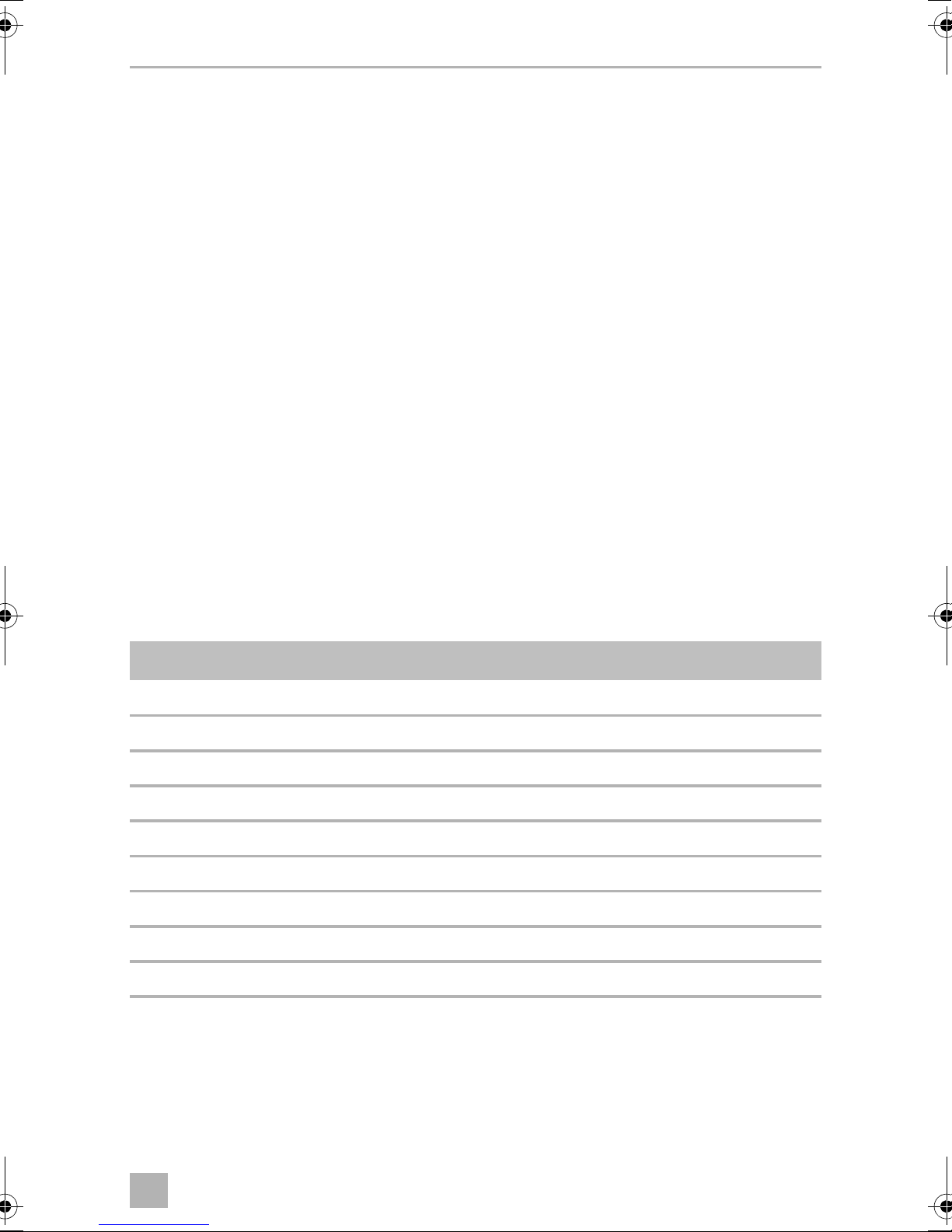
3 Scope of delivery . . . . . . . . . . . . . . . . . . . . . . . . . . . . . . . . . . . . . . . . . . . . . . .5
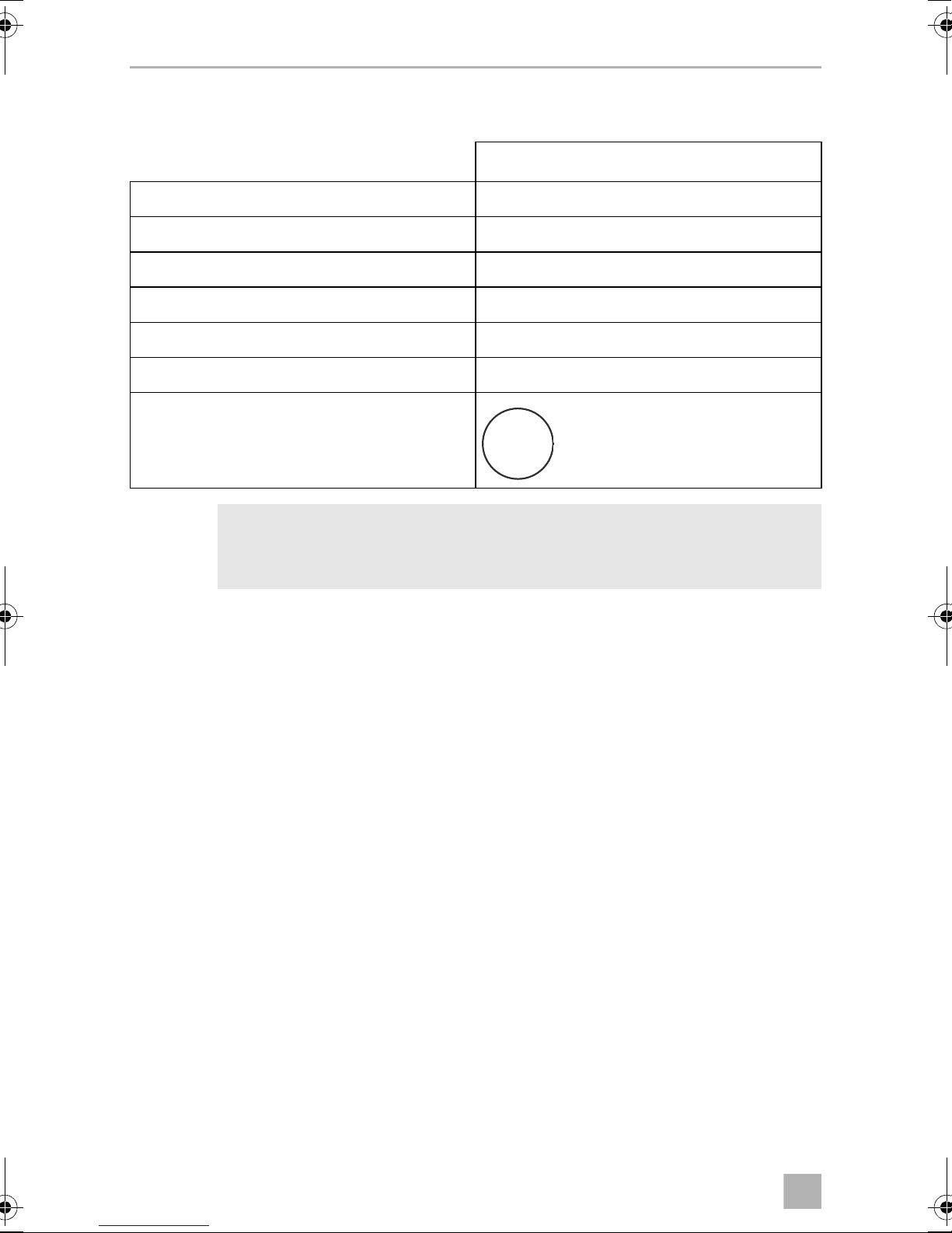
4 Accessories . . . . . . . . . . . . . . . . . . . . . . . . . . . . . . . . . . . . . . . . . . . . . . . . . . . .6
5 Intended use . . . . . . . . . . . . . . . . . . . . . . . . . . . . . . . . . . . . . . . . . . . . . . . . . . .6
6 Instructions before installation . . . . . . . . . . . . . . . . . . . . . . . . . . . . . . . . . . . . .6
7 Fitting the parking aid . . . . . . . . . . . . . . . . . . . . . . . . . . . . . . . . . . . . . . . . . . . .7
8 Connecting the parking aid . . . . . . . . . . . . . . . . . . . . . . . . . . . . . . . . . . . . . . .8
9 Registering and identifying sensors . . . . . . . . . . . . . . . . . . . . . . . . . . . . . . . . .9
10 Detection range . . . . . . . . . . . . . . . . . . . . . . . . . . . . . . . . . . . . . . . . . . . . . . .10
11 Setting the system. . . . . . . . . . . . . . . . . . . . . . . . . . . . . . . . . . . . . . . . . . . . . . 11
12 Performing a functional test . . . . . . . . . . . . . . . . . . . . . . . . . . . . . . . . . . . . . .12
13 Using the parking aid . . . . . . . . . . . . . . . . . . . . . . . . . . . . . . . . . . . . . . . . . . .13
14 Troubleshooting . . . . . . . . . . . . . . . . . . . . . . . . . . . . . . . . . . . . . . . . . . . . . . .13
15 Warranty . . . . . . . . . . . . . . . . . . . . . . . . . . . . . . . . . . . . . . . . . . . . . . . . . . . . .15
16 Disposal. . . . . . . . . . . . . . . . . . . . . . . . . . . . . . . . . . . . . . . . . . . . . . . . . . . . . .15
17 Technical data . . . . . . . . . . . . . . . . . . . . . . . . . . . . . . . . . . . . . . . . . . . . . . . . .16
3
Page 6
EN
Explanation of symbols MWE7006
1 Explanation of symbols
WARNING!
!
A
Safety instruction: Failure to observe this instruction can cause fatal or
serious injury.
NOTICE!
Failure to observe this instruction can cause material damage and impair
the function of the product.
NOTE
Supplementary information for operating the product.
I
2 Safety and installation instructions
The following texts only complete the figures on the supplementary sheet.
They do not contain the full installation and operating instructions. Please
observe the figures on the supplementary sheet.
Please observe the prescribed safety instructions and stipulations from the
vehicle manufacturer and service workshops.
Observe the applicable legal regulations.
The manufacturer accepts no liability for damage in the following cases:
• Damage to the product resulting from mechanical influences and excess voltage
• Alterations to the product without express permission from the manufacturer
• Use for purposes other than those described in the operating manual
WARNING!
!
• Secure the parts of the parking aid installed in the vehicle in such a way
that they cannot become loose under any circumstances (sudden
braking, accidents) and cause injuries to the occupants of the
vehicle.
• Do not fit the parts of the parking aid installed where an airbag may
open. This could cause injury if the airbag opens.
• The parking aid is intended as an additional aid, which means it does
not relieve you of the obligation to take due care when manoeuvring.
4
Page 7
EN
MWE7006 Scope of delivery
NOTICE!
A
• Installing the parking aid can cause problems on vehicles with LED tail
lights.
• If you would like to install the sensors on metal bumpers, you require
suitable adapters (not included in the scope of delivery).
• Do not expose the control electronics to dampness.
• The control electronics must not be installed near other control
modules.
• The sensors may not cover signal lamps.
• When fitting the sensors, make sure there are no objects fixed to the
vehicle (such as a bicycle rack) that are in the detection range of the
sensors.
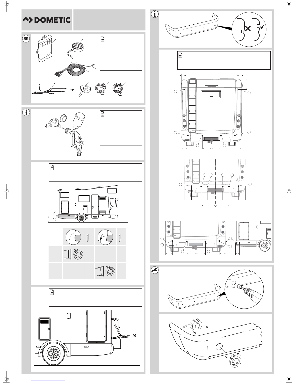
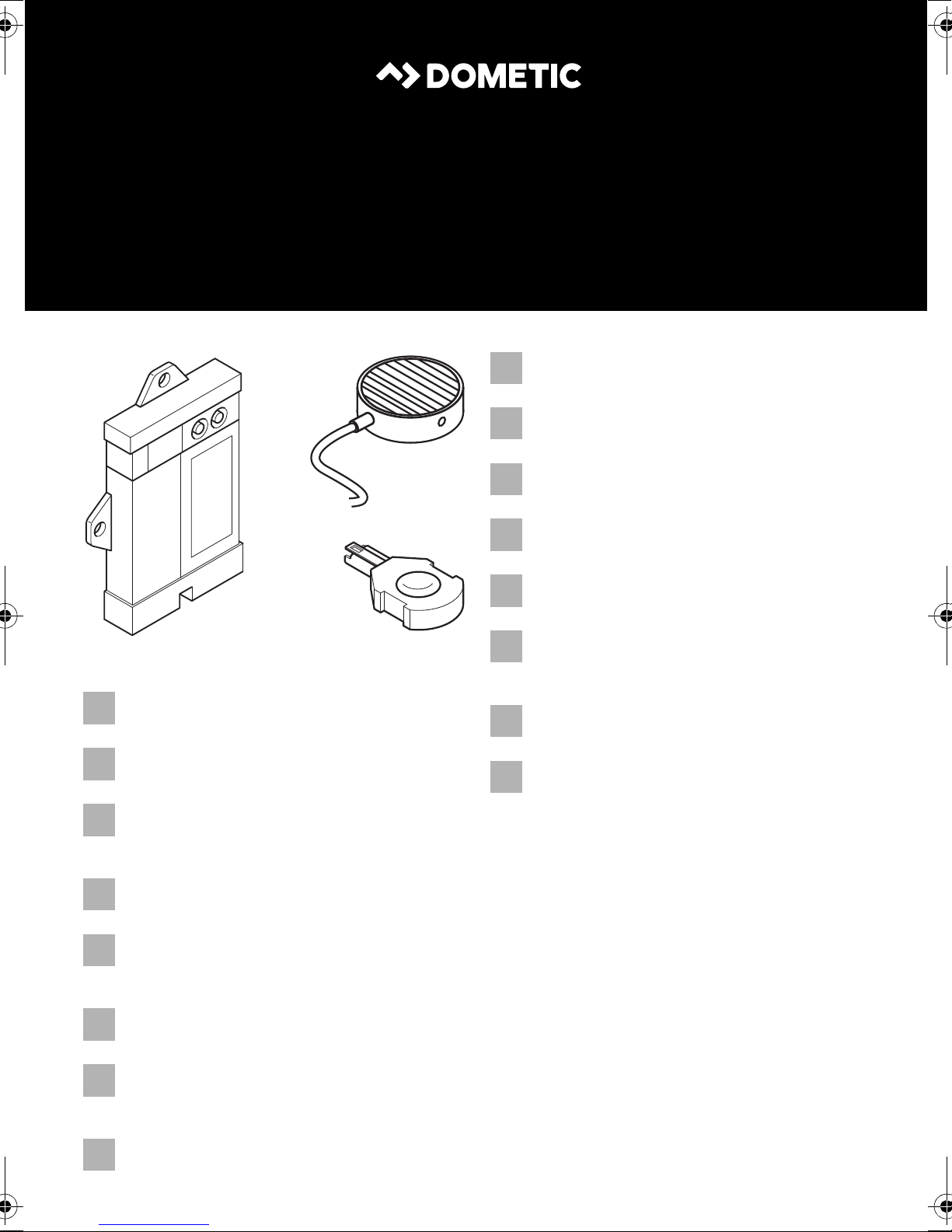
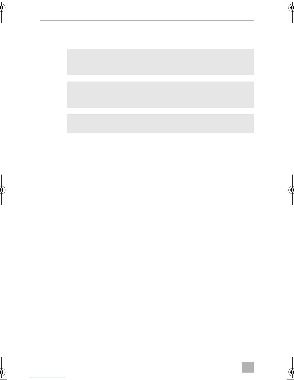
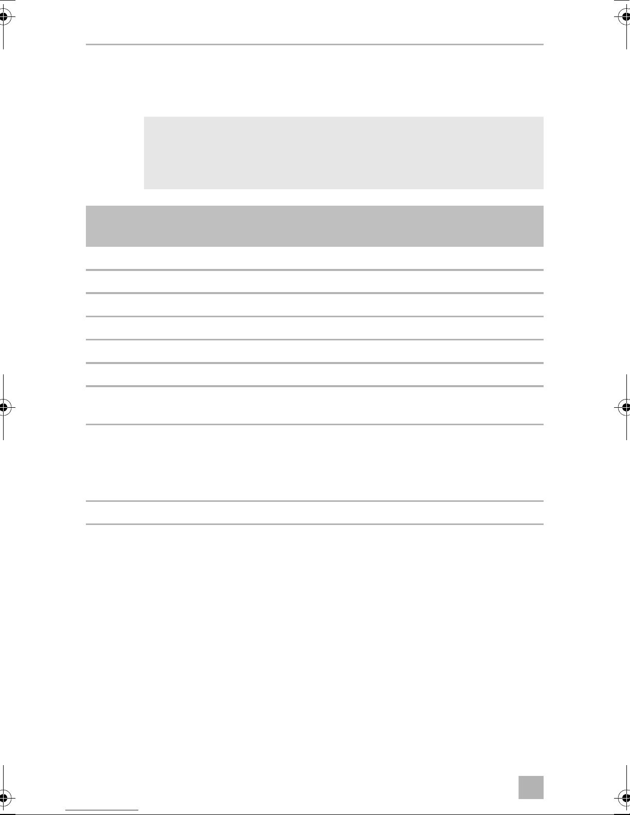
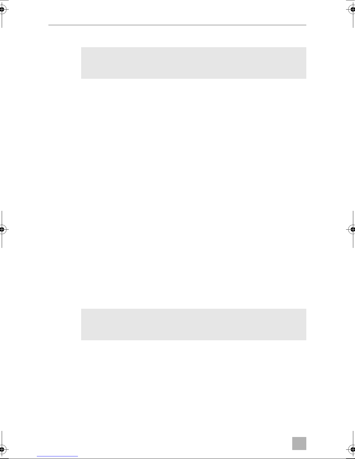
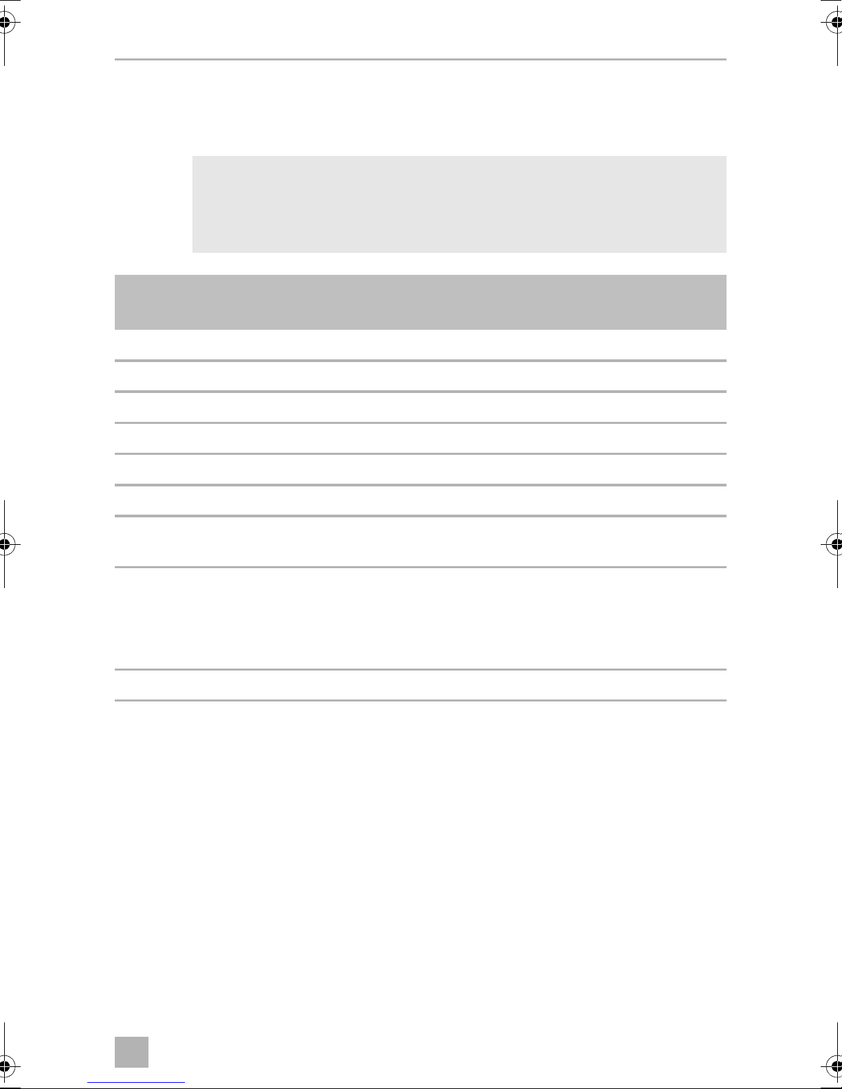
3Scope of delivery
See fig. 1
No. Quantity Designation Ref. no.
1 1 Control electronics 9101500069
21Loudspeaker
3 1 Control electronics connection cable
4 1 Sensor distributor 9101500067
5 6 Ultrasonic sensors with connection cable 9101500070
6 6 0° sensor holder with cover ring
7 6 10° sensor holder with cover ring
– 2 Extension cable, 3 m
– 1 Fastening material
5
Page 8
EN
Accessories MWE7006
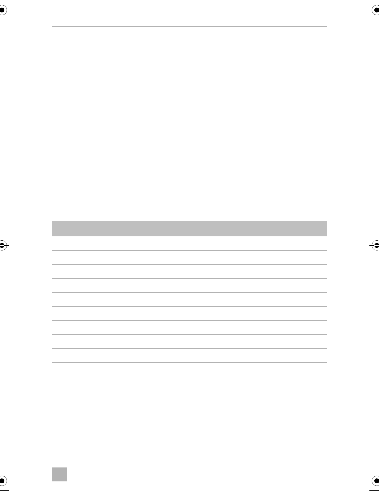
4Accessories
Available as accessories (not included in the scope of delivery):
Designation Ref. no.
Sensor holder for metal bumper 9101500015
Sensor extension cable, 1.5 m 9103555747
Subframe sensor holder (fig. c 1) 9101500078
Rubber sensor holder for surface mounting (fig. c 2) 9101500071
Loudspeaker MWD-900
LED display 9101500079
5 Intended use
Dometic MWE7006 (ref. no. 9600000359) is a parking aid based on ultrasound.
When manoeuvring, it monitors the space behind the vehicle and provides an audible and visible warning signal for any obstacles it detects.
MWE7006 is designed for installation in motor homes.
6 Instructions before installation
6.1 Painting the sensors
See fig. 2
NOTE
I
The sensors may be painted. The manufacturer recommends having the
sensors painted by a specialist workshop.
6
Page 9
EN
MWE7006 Fitting the parking aid
6.2 Determining the place of installation for the sensors
See fig. 3 to fig. 6
NOTE
I
Note the following during installation:
• The area around the sensors must be free from other objects.
• The distance from the sensors to the ground should be at least 45 cm and a
maximum of 60 cm (fig. 3).
• Note that the installation angle depends on the installation height.
Select the right sensor holder and the appropriate drill diameter by consulting
the table in fig. 3.
The sensors must be correctly aligned for the device to work properly.
If they point to the ground, irregularities and bumps on the surface may
be interpreted as obstacles. If they point too far up, obstacles will not be
detected at all.
• If a bicycle rack has been fitted, then install the sensors at least 30 cm below it
(fig. 4).
Supplement to fig. 6
➤ Observe the intervals between sensors.
NOTE
You can also distribute the sensors as shown in alternative B and C.
I
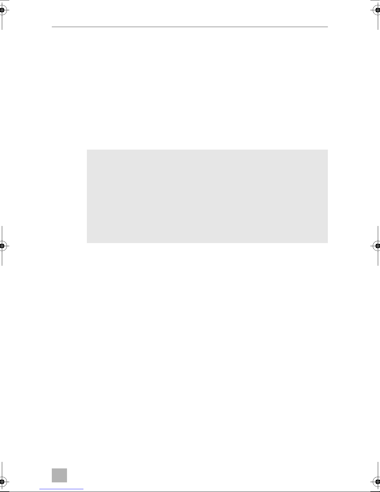
7 Fitting the parking aid
See fig. 7 to fig. 0
Supplement to fig. 8
NOTICE! Risk of malfunction!
A
Align the sensor holders so that the fastening lugs are horizontal. Otherwise, there is no guarantee the parking aid will function correctly.
➤ Push the sensor holders into the holes until they lock into place.
Supplementary to fig. 0
➤ Ensure that the loudspeaker is switched on (Middle or High position).
7
Page 10
EN
Connecting the parking aid MWE7006
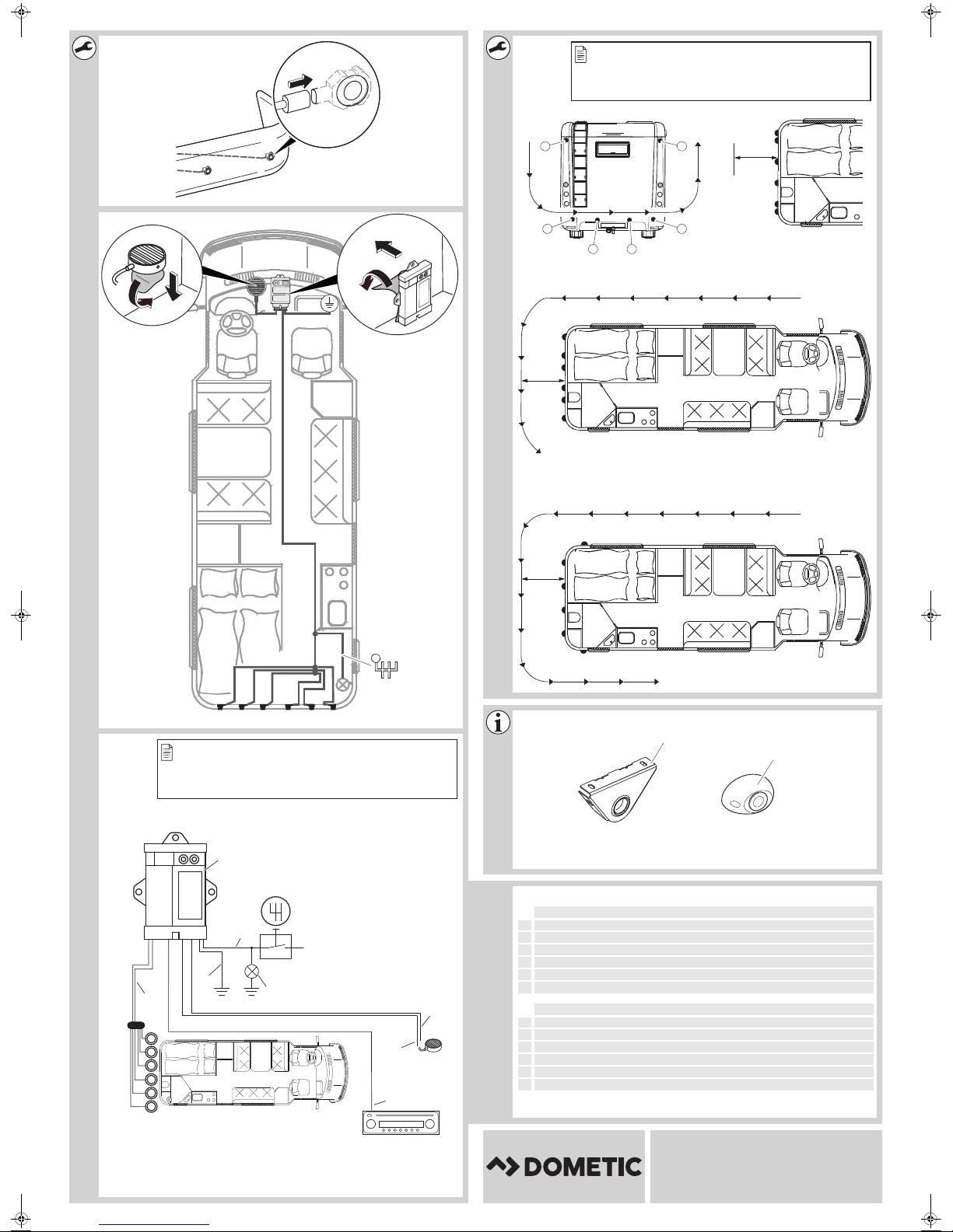
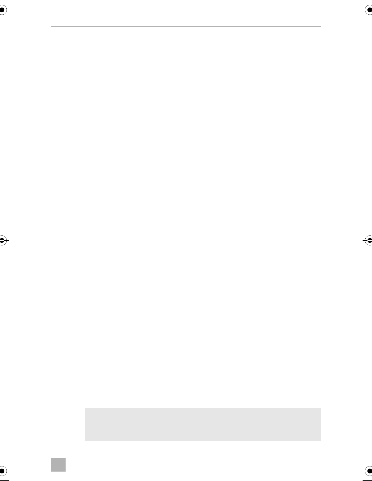
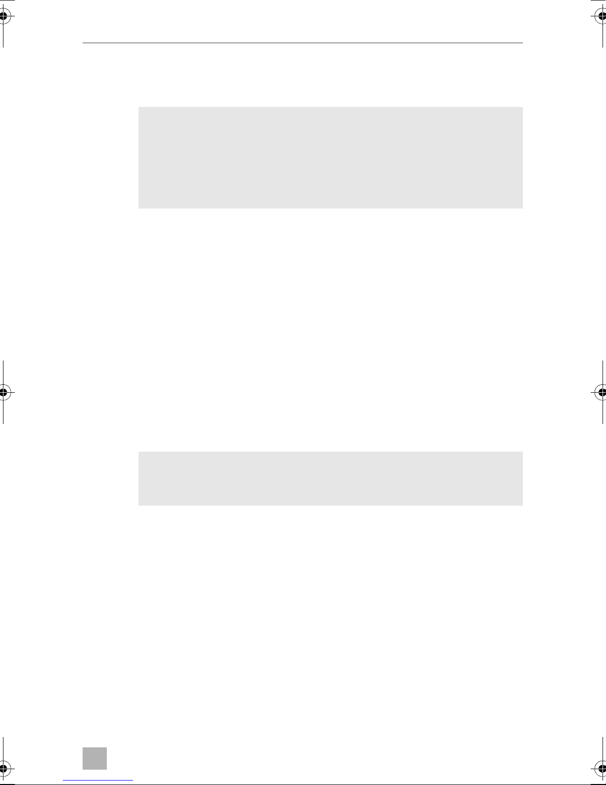
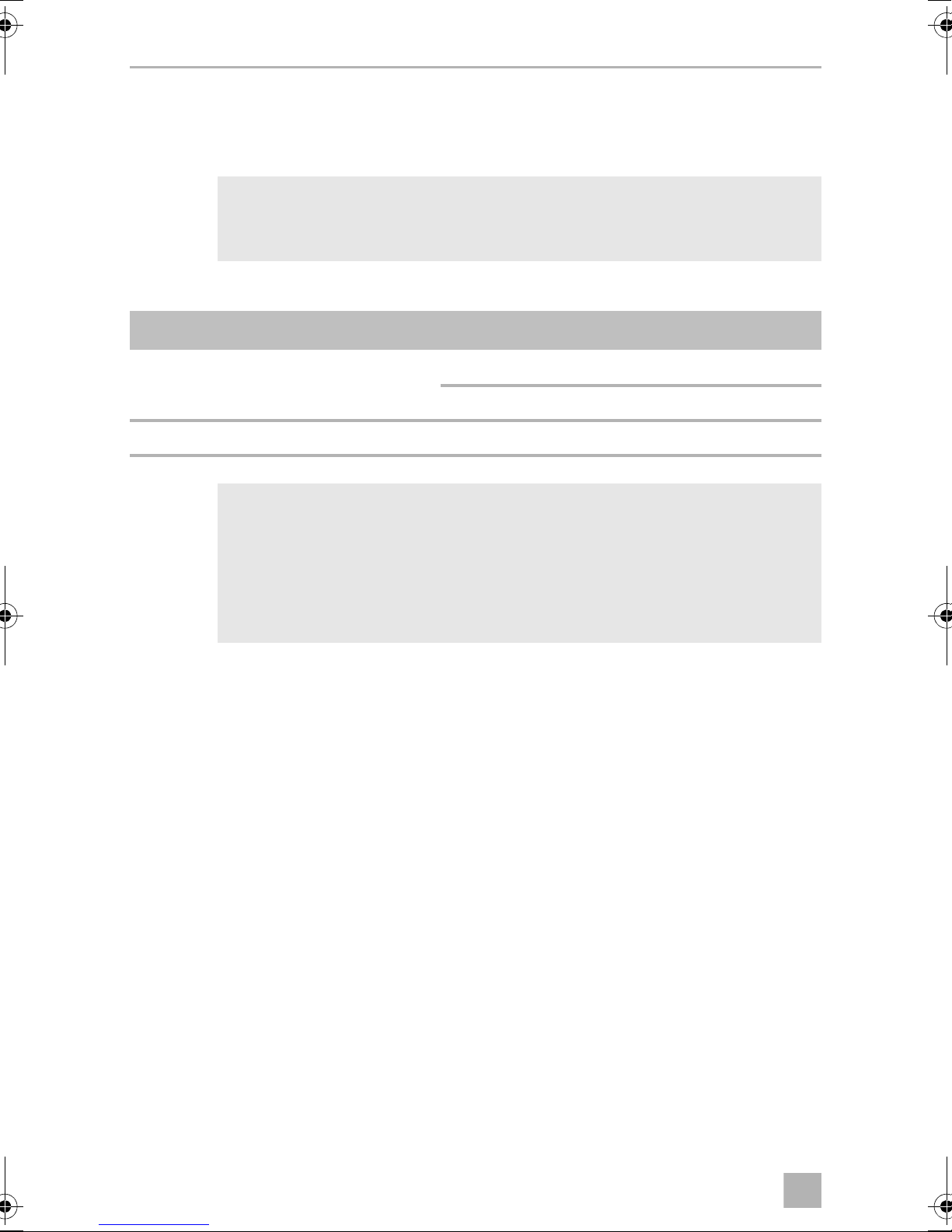
8 Connecting the parking aid
See fig. a
NOTE
I
On some vehicles, the reversing light only works when the ignition is
switched on. In this case, you must switch on the ignition to identify the
positive and earth cables.
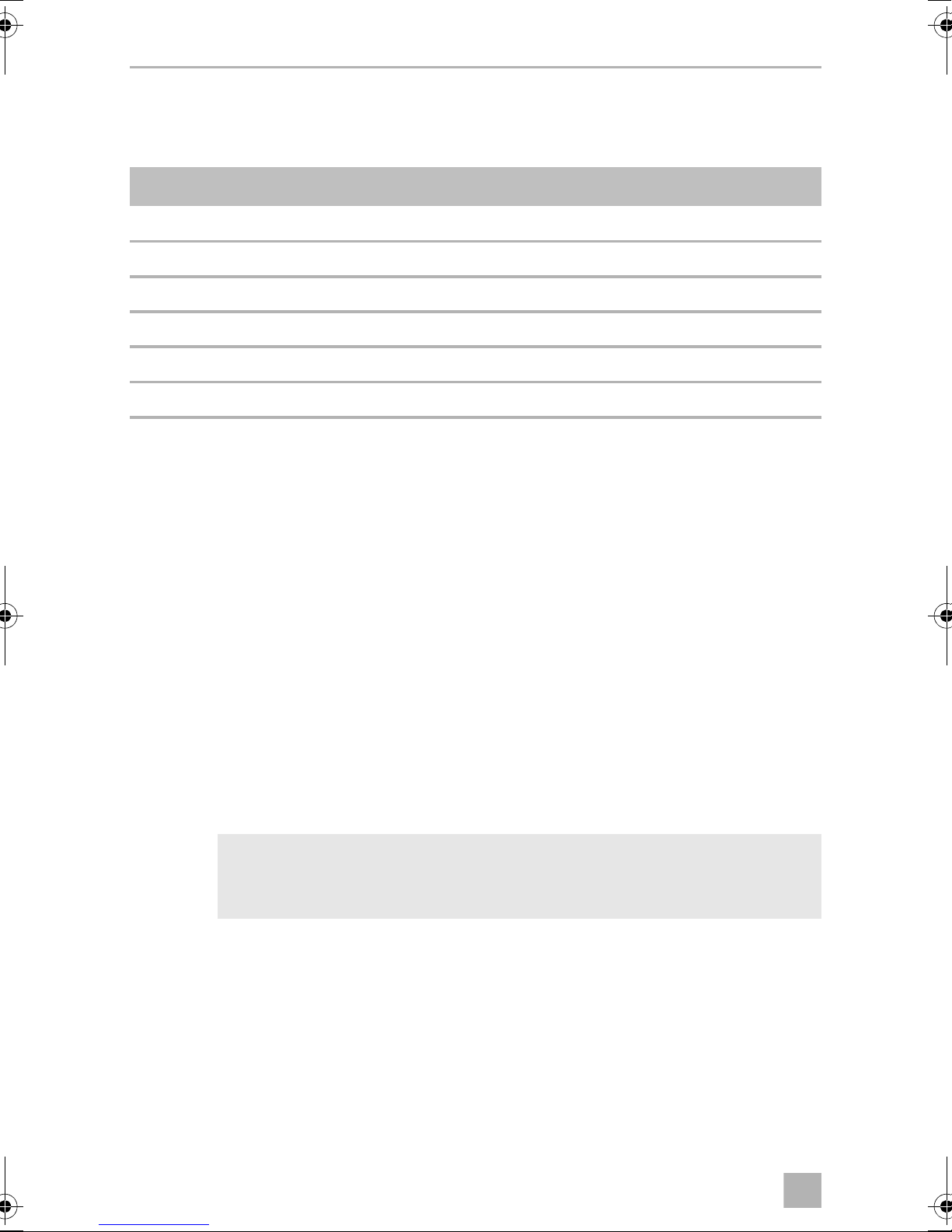
No. Designation
1 Control electronics –
2 Reversing light –
3 Blue/black cable: connection to the reversing light 14
4 Brown cable: connection to earth 2
5 Yellow wire from the loudspeaker 15
6 Blue wire from the loudspeaker 3
7 Red/grey cable: connection to the radio's mute connection
(optional)
8 Sensors connection cable 9/21
9 Sensors –
Plug socket
for plug
(12/24)
(10/22)
(11/23)
6
8
Page 11
EN
MWE7006 Registering and identifying sensors
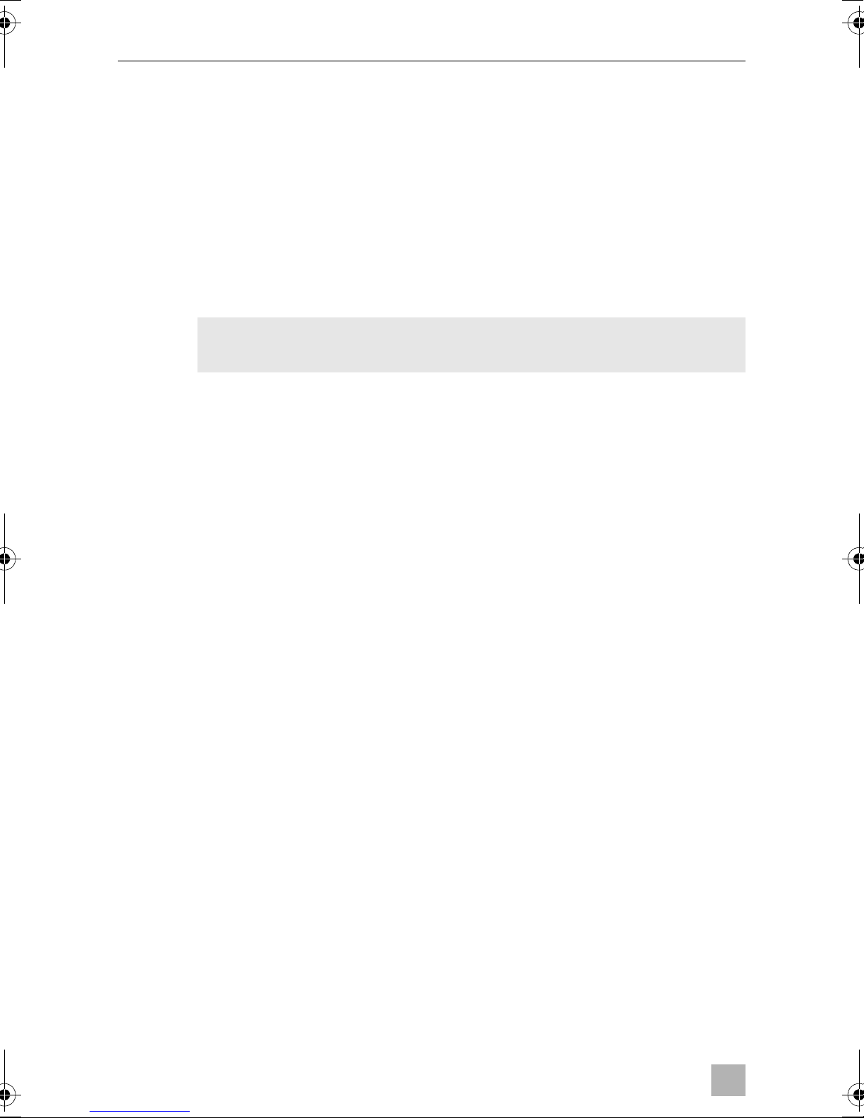
9 Registering and identifying sensors
The sensors and their position must be registered by the control unit. To do this,
proceed as follows:
➤ Switch on the ignition.
➤ Engage the reverse gear.
✓ The control unit registers the sensors connected.
✓ The display on the control unit shows LE.
✓ The loudspeaker emits short acoustic signals repeatedly.
Once the registration is complete, LE flashes on the display. The sensors must now
be identified by the control unit.
➤ Park the vehicle so that it is surrounded by at least 1.5 m of free space to ensure
the sensors cannot detect any obstacles.
➤ Switch the ignition off and on again.
➤ Engage the reverse gear.
➤ Press both buttons on the control unit for more than three seconds.
✓ The control unit registers the sensors connected.
Once the registration is complete, the loudspeaker emits a long acoustic signal. The
sensors must now be identified by the control unit.
The display shows a running light and the loudspeaker emits short acoustic signals
repeatedly.
➤ Proceed as follows in accordance with the installation alternative you selected
(fig. 6):
– Alternative A: Use a large object approx. 0.5 m² in size (e.g. a piece of sturdy
paper) and go to sensors 1 to 6 successively (fig. b A)
– Alternatives B and C: Starting at the driver's door, walk around the vehicle
from the first to the last sensor (fig. b B and C).
✓ The loudspeaker acknowledges each sensor detected with a short acoustic
signal.
Once identification is complete, the loudspeaker emits a long acoustic signal.
NOTE
I
If an error occurs during this procedure, you can restart the procedure
by pressing both buttons together for longer than three seconds.
9
Page 12
EN
Detection range MWE7006
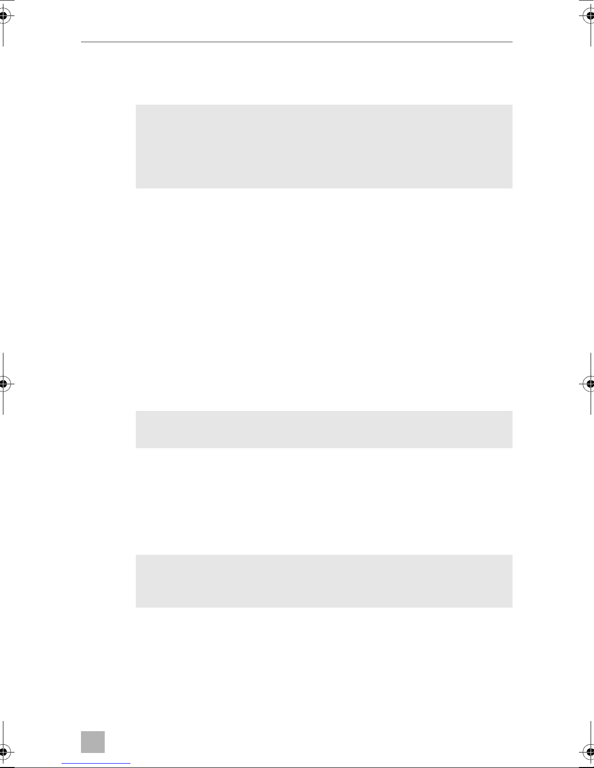
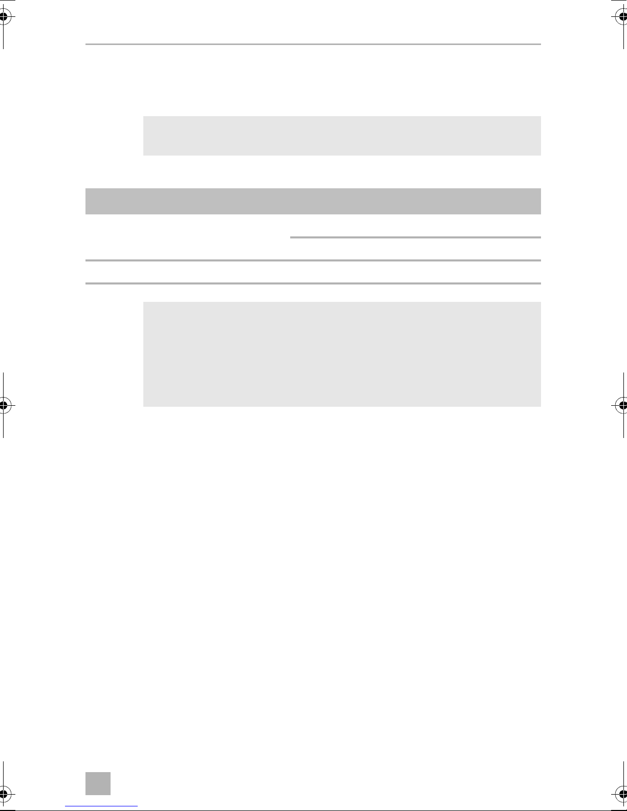
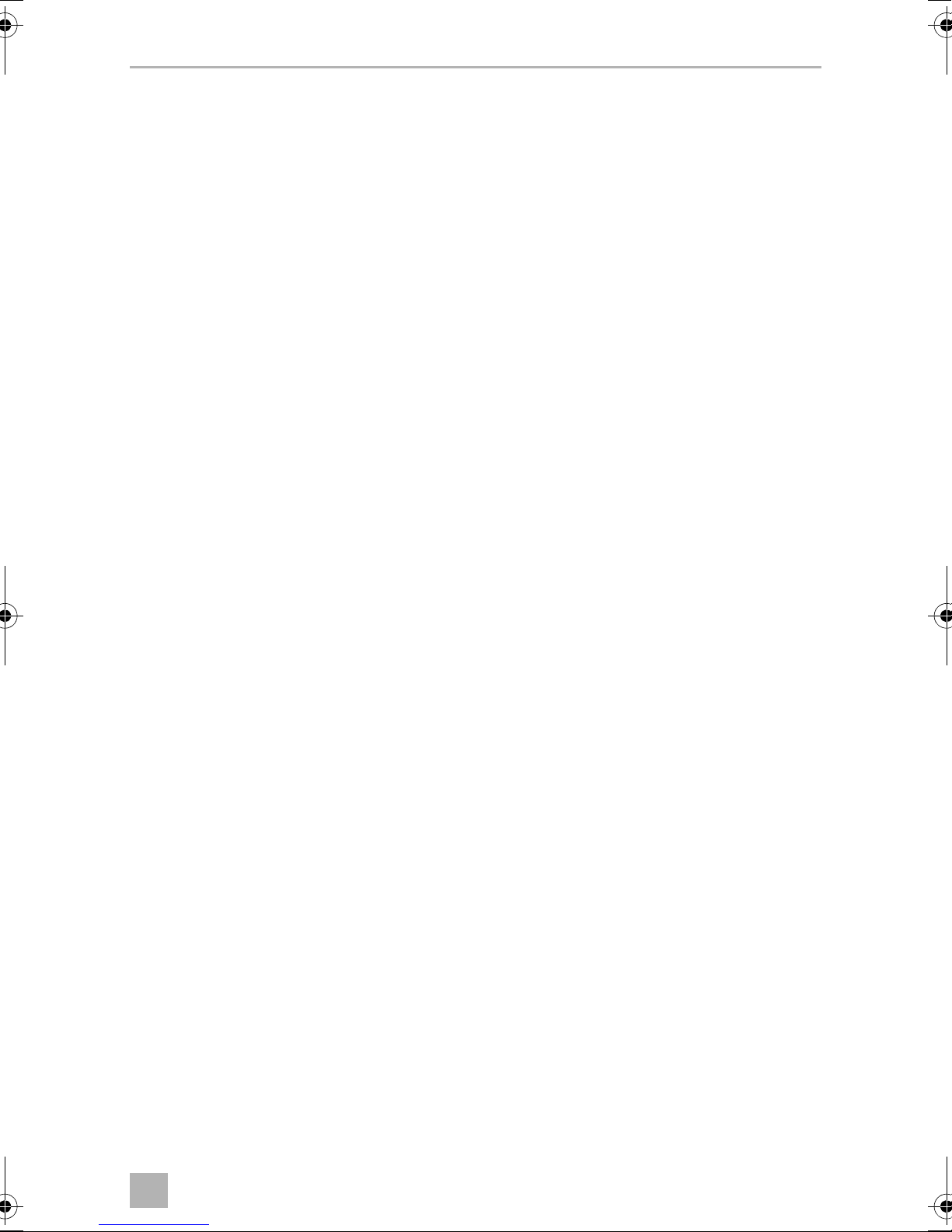
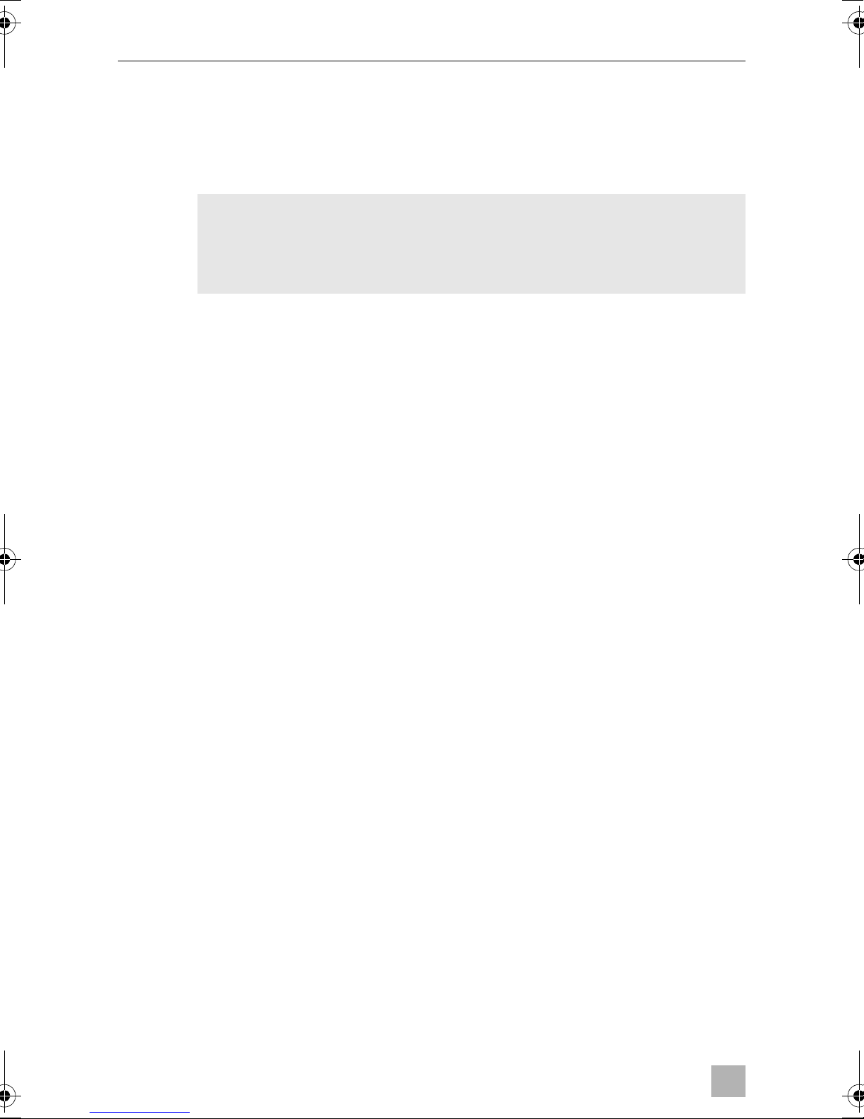
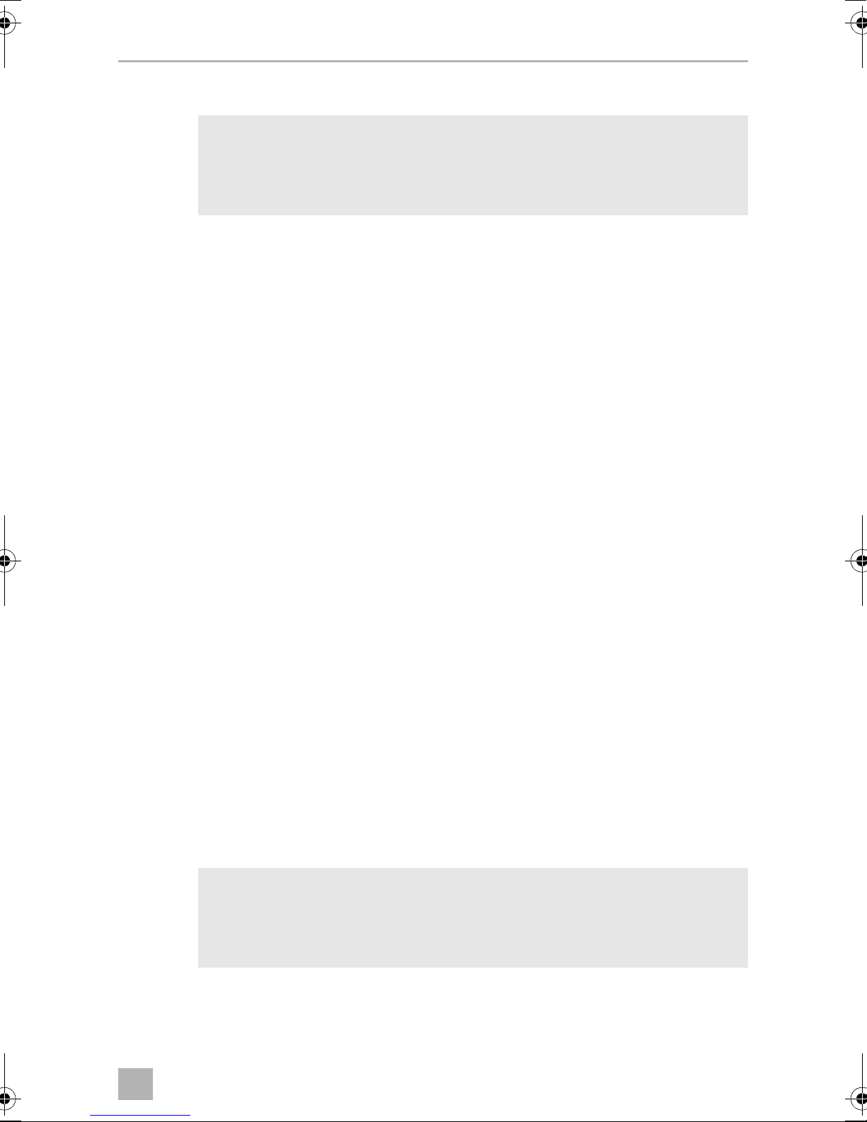
10 Detection range
See fig. d
The detection range of the parking aid is divided into four zones:
• Zone 1
This zone is the first limit range. Small objects or those with poor reflective
characteristics may not be detected here.
• Zone 2
Nearly all objects in this zone are displayed.
• Zone 3
Virtually all objects are displayed in this zone, but some objects may end up in the
blind spot of the sensors.
• Stop zone (4)
If there are objects in this zone, the parking aid emits a continuous tone warning
you to stop.
Virtually all objects are displayed in this zone, but some objects may end up in
the blind spot of the sensors.
There must be no objects such as bicycle racks or spare wheels in the detection
range of the sensors, as this would result in an incorrect display.
The display of fixed objects, such as a trailer coupling or a part of the spare
wheel, can be suppressed (parameters 51, 52 and 53).
10
Page 13
EN
MWE7006 Setting the system
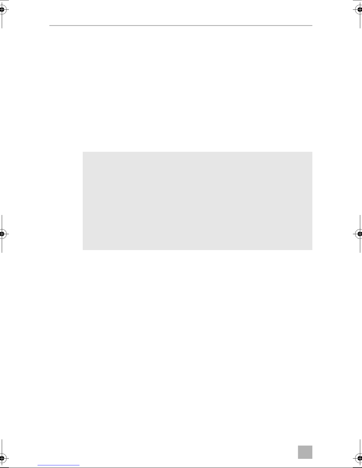
11 Setting the system
See fig. d to fig. g
WARNING!
Incorrect settings can impair operational safety.
!
The control electronics have the following control elements:
No. in fig. e Designation
1DisplayF5 Factory settings activated
C5 Your own settings
2, 3 Buttons for setting the system
NOTE
I
• To save the settings, disengage and engage the reverse gear and
wait for 2 s.
• To cancel setting the parameters without saving your changes,
or to stop the entire setting process: refrain from pressing any
buttons for a while.
Restoring the factory settings
➤ Press the right-hand button for longer than 2 s to access programming mode.
➤ The display now shows 01.
➤ Press both buttons for longer than two seconds.
✓ The display shows F5.
11
Page 14
EN
Performing a functional test MWE7006
Suppressing use of a bicycle rack or trailer
NOTE
I
You can use an external switch (not included in the scope of delivery) to:
• Switch over the standard stop zone (parameters 47, 48 and 49) to a higher stop
zone (parameters 61, 62 and 63) if you are using a bicycle rack and this is being
folded out.
• Deactivate the parking aid while you are using a trailer.
To do this, proceed as follows:
➤ Connect pin 17 of the connection cable plug to earth using the external switch.
➤ For trailers only: Set parameter 56 to 00.
You can program PIN 17 either for switching over the stop zones or for
deactivation when using a trailer.
Suppressing the display of a trailer coupling or an external spare wheel
➤ Set the parameters 51, 52 and 53 to suit your trailer coupling or your spare wheel.
12 Performing a functional test
Conduct the functional test of the sensors as follows:
➤ Switch on the ignition and engage the reverse gear.
Be very careful when you operate the device for the first time, and make sure that you
familiarize yourself with the various sequences of beeps.
WARNING!
!
In zone 4, some obstacles may not be detected, because they are no
longer within range of the sensors (design-related characteristic).
12
Page 15
EN
MWE7006 Using the parking aid
13 Using the parking aid
The sensors are activated automatically when you engage the reverse gear with the
ignition on or the engine running. An activation signal is emitted (two short tones).
As soon as there is an obstacle within the detection range, a repeated signal tone is
emitted.
As you approach, the tone sequence changes, depending on the zone in which the
obstacle is, thereby indicating the distance.
Be very careful the first time you use the system, until you are familiar with the various
sequences of beeps.
WARNING!
!
Stop the vehicle immediately and investigate the situation (getting out if
necessary), if the following happens while you are manoeuvring:
the device first indicates an obstacle and the tone sequence speeds up
normally (e.g. from slow to medium) when manoeuvring. the signal tone
suddenly slows down, or no obstacle is indicated at all.
This means that the original obstacle is in the blind spot of the sensors
(construction-related characteristic), and there is still a potential for
collision.
14 Troubleshooting
The device shows no function.
The cables to the reversing light are not connected or are not properly connected.
The plugs for the sensors are not connected or are not correctly plugged into the
control electronics.
➤ Check the plugs and make sure they lock into place.
13
Page 16
EN
Troubleshooting MWE7006
Low error tone for three seconds after engaging reverse gear
One or more sensors are defective or no longer connected to the control
electronics. The display shows the defective sensor:
• for example, E1 for sensor 1
Sensor 1 has the shortest connection cable, sensor 6 the longest.
• If more than one sensor is defective, they are shown in succession.
➤ Check the plugs and make sure they lock into place.
➤ Replace the defective sensor(s).
NOTICE!
The system does not work if one or more sensors are defective.
A
No acoustic signals
The loudspeaker is switched off, or incorrectly connected.
➤ Check whether the loudspeaker is switched on.
➤ Check whether the loudspeaker is connected correctly.
➤ Set parameter 01 to “1” or “2” (see chapter “Setting the system” on page 11).
Device indicates obstacles incorrectly
False alarms may have the following causes:
• Dirt or frost on the sensors.
➤ Clean the sensors.
• The sensors were incorrectly installed.
➤ Adjust the position of the sensors (fig. 3).
➤ If necessary, use parameters 41, 42 and 43 to adjust the sensitivity of the sensors
(see chapter “Setting the system” on page 11).
• The sensors are in contact with the vehicle chassis.
➤ Separate the sensors from the chassis.
The spare wheel is causing false alarms
➤ Set the parameters 51, 52 and 53 to suit your spare wheel (see chapter “Setting the
system” on page 11).
14
Page 17
EN
MWE7006 Warranty
Objects on the vehicle (e.g. spare wheel) are causing false alarms
➤ Set parameters 51, 52 and 53 to suit your object to 00 or 01 (see chapter “Setting
the system” on page 11).
➤ Adjust the stop zone using the parameters 47, 48 and 49 to suit your object (see
chapter “Setting the system” on page 11).
15 Warranty
The statutory warranty period applies. If the product is defective, please contact the
manufacturer's branch in your country (see the back of the instruction manual for the
addresses) or your retailer.
For repair and guarantee processing, please send the following items:
• Defect components
• A copy of the receipt with purchasing date
• A reason for the claim or description of the fault
16 Disposal
➤ Place the packaging material in the appropriate recycling waste bins wherever
possible.
If you wish to finally dispose of the product, ask your local recycling centre
or specialist dealer for details about how to do this in accordance with the
M
applicable disposal regulations.
15
Page 18
EN
Technical data MWE7006
E8
17 Technical data
MWE7006
Ref. no.: 9600000359
Detection range: approx. 0.60 m up to 3 m
Ultrasound frequency: 58 kHz
Supply voltage: 10 – 32 V
Current: Max. 350 mA
Operating temperature: –35 °C to 70 °C
Certification:
I
NOTE
The sensors may be painted. The manufacturer recommends having the
sensors painted by a specialist workshop.
16
Page 19

DE
MWE7006
Bitte lesen Sie diese Anleitung vor Einbau und Inbetriebnahme sorgfältig
durch und bewahren Sie sie auf. Geben Sie sie im Falle einer Weitergabe
des Produktes an den Nutzer weiter.
Inhaltsverzeichnis
1 Erklärung der Symbole . . . . . . . . . . . . . . . . . . . . . . . . . . . . . . . . . . . . . . . . . .18
2 Sicherheits- und Einbauhinweise . . . . . . . . . . . . . . . . . . . . . . . . . . . . . . . . . .18
3 Lieferumfang . . . . . . . . . . . . . . . . . . . . . . . . . . . . . . . . . . . . . . . . . . . . . . . . . .19
4 Zubehör. . . . . . . . . . . . . . . . . . . . . . . . . . . . . . . . . . . . . . . . . . . . . . . . . . . . . 20
5 Bestimmungsgemäßer Gebrauch . . . . . . . . . . . . . . . . . . . . . . . . . . . . . . . . 20
6 Hinweise vor dem Einbau. . . . . . . . . . . . . . . . . . . . . . . . . . . . . . . . . . . . . . . 20
7 Einparkhilfe montieren . . . . . . . . . . . . . . . . . . . . . . . . . . . . . . . . . . . . . . . . . 22
8 Einparkhilfe anschließen . . . . . . . . . . . . . . . . . . . . . . . . . . . . . . . . . . . . . . . . 23
9 Sensoren registrieren und identifizieren . . . . . . . . . . . . . . . . . . . . . . . . . . . 24
10 Erfassungsbereich. . . . . . . . . . . . . . . . . . . . . . . . . . . . . . . . . . . . . . . . . . . . . 25
11 System einstellen. . . . . . . . . . . . . . . . . . . . . . . . . . . . . . . . . . . . . . . . . . . . . . 26
12 Funktion testen . . . . . . . . . . . . . . . . . . . . . . . . . . . . . . . . . . . . . . . . . . . . . . . 27
13 Einparkhilfe benutzen . . . . . . . . . . . . . . . . . . . . . . . . . . . . . . . . . . . . . . . . . . 28
14 Fehler suchen . . . . . . . . . . . . . . . . . . . . . . . . . . . . . . . . . . . . . . . . . . . . . . . . 28
15 Gewährleistung. . . . . . . . . . . . . . . . . . . . . . . . . . . . . . . . . . . . . . . . . . . . . . . 30
16 Entsorgung . . . . . . . . . . . . . . . . . . . . . . . . . . . . . . . . . . . . . . . . . . . . . . . . . . 30
17 Technische Daten . . . . . . . . . . . . . . . . . . . . . . . . . . . . . . . . . . . . . . . . . . . . . .31
17
Page 20

DE
Erklärung der Symbole MWE7006
1 Erklärung der Symbole
WARNUNG!
!
A
Sicherheitshinweis: Nichtbeachtung kann zu Tod oder schwerer
Verletzung führen.
ACHTUNG!
Nichtbeachtung kann zu Materialschäden führen und die Funktion des
Produktes beeinträchtigen.
HINWEIS
Ergänzende Informationen zur Bedienung des Produktes.
I
2 Sicherheits- und Einbauhinweise
Die folgenden Texte ergänzen die Abbildungen auf dem Beiblatt lediglich.
Sie alleine sind keine vollständigen Einbau- und Bedienhinweise! Bitte
beachten Sie unbedingt die Abbildungen auf dem Beiblatt!
Beachten Sie die vom Fahrzeughersteller und vom Kfz-Handwerk
vorgeschriebenen Sicherheitshinweise und Auflagen!
Beachten Sie die geltenden gesetzlichen Vorschriften.
Der Hersteller übernimmt in folgenden Fällen keine Haftung für Schäden:
• Beschädigungen am Produkt durch mechanische Einflüsse und Überspannungen
• Veränderungen am Produkt ohne ausdrückliche Genehmigung vom Hersteller
• Verwendung für andere als die in der Anleitung beschriebenen Zwecke
WARNUNG!
!
• Befestigen Sie die im Fahrzeug montierten Teile der Einparkhilfe so,
dass sie sich unter keinen Umständen (scharfes Abbremsen, Verkehrsunfall) lösen und zu Verletzungen der Fahrzeuginsassen führen
können.
• Montieren Sie die im Fahrzeug montierten Teile der Einparkhilfe nicht
im Wirkungsbereich eines Airbags. Sonst besteht Verletzungsgefahr,
wenn der Airbag auslöst.
18
Page 21
DE
MWE7006 Lieferumfang
• Die Einparkhilfe soll Sie zusätzlich unterstützen, d. h. das Gerät
entbindet Sie nicht von Ihrer besonderen Vorsichtspflicht beim
Rangieren.
ACHTUNG!
A
• Bei Fahrzeugen mit LED-Rücklichtern kann der Einbau der Einparkhilfe
zu Störungen führen.
• Wenn Sie die Sensoren in Metall-Stoßfänger montieren möchten,
benötigen Sie geeignete Adapter (nicht im Lieferumfang enthalten).
• Die Steuerelektronik darf keiner Feuchtigkeit ausgesetzt sein.
• Die Steuerelektronik darf nicht in der Nähe von anderen Steuer-
modulen montiert werden.
• Die Sensoren dürfen keine Signallampen verdecken.
• Achten Sie bei der Montage der Sensoren darauf, dass sich keine am
Fahrzeug festangebauten Objekte (z. B. Fahrradträger) im Erfassungsbereich der Sensoren befinden.
3 Lieferumfang
Siehe Abb. 1
Nr. Menge Bezeichnung Art.-Nr.
1 1 Steuerelektronik 9101500069
2 1 Lautsprecher
3 1 Anschlusskabel Steuerelektronik
4 1 Verteiler Sensoren 9101500067
5 6 Ultraschall-Sensoren mit Anschlusskabel 9101500070
6 6 Sensorhalter 0° mit Abdeckring
7 6 Sensorhalter 10° mit Abdeckring
– 2 Verlängerungskabel 3 m
– 1 Befestigungsmaterial
19
Page 22

DE
Zubehör MWE7006
4Zubehör
Als Zubehör erhältlich (nicht im Lieferumfang enthalten):
Bezeichnung Art.-Nr.
Sensorhalter für Stoßfänger aus Metall 9101500015
Verlängerungskabel Sensor 1,5 m 9103555747
Unterbausensorhalter (Abb. c 1) 9101500078
Gummisensorhalter für Aufbaumontage (Abb. c 2) 9101500071
Lautsprecher MWD-900
LED-Display 9101500079
5 Bestimmungsgemäßer Gebrauch
Dometic MWE 7006 (Art.-Nr. 9600000359) ist eine Einparkhilfe auf Ultraschallbasis.
Sie überwacht beim Rangieren den Raum hinter dem Fahrzeug und warnt akustisch
vor Hindernissen, die durch das Gerät erfasst werden.
MWE7006 ist zum Einbau in Wohnmobile ausgelegt.
6 Hinweise vor dem Einbau
6.1 Sensoren lackieren
Siehe Abb. 2
HINWEIS
I
Die Sensoren dürfen lackiert werden. Der Hersteller empfiehlt, die
Lackierung der Sensoren von einer Fachwerkstatt vornehmen zu lassen.
20
Page 23
DE
MWE7006 Hinweise vor dem Einbau
6.2 Einbauort für die Sensoren festlegen
Siehe Abb. 3 bis Abb. 6
HINWEIS
I
Beachten Sie Folgendes bei der Montage:
• Der Bereich um die Sensoren muss frei von anderen Objekten sein.
• Der Abstand der Sensoren zum Boden sollte mindestens 45 cm und maximal
60 cm betragen (Abb. 3).
• Beachten Sie, dass der Montagewinkel von der Montagehöhe abhängt.
Wählen Sie entsprechend der Tabelle in Abb. 3 den passenden Sensorhalter
sowie den zugehörigen Bohrdurchmesser.
Wichtig für die einwandfreie Funktion des Gerätes ist die korrekte
Ausrichtung der Sensoren.
Wenn diese auf den Boden zeigen, werden z. B. Bodenunebenheiten
als Hindernis angezeigt. Wenn sie zu weit nach oben zeigen, werden
vorhandene Hindernisse nicht erkannt.
• Wenn ein Fahrradträger montiert ist, montieren Sie die Sensoren mindestens
30 cm darunter (Abb. 4).
Ergänzung zu Abb. 6
➤ Beachten Sie die Abstände der Sensoren.
HINWEIS
I
Sie können die Sensoren auch so verteilen wie in Alternative B und C
gezeigt.
21
Page 24
DE
Einparkhilfe montieren MWE7006
7 Einparkhilfe montieren
Siehe Abb. 7 bis Abb. 0
Ergänzung zu Abb. 8
ACHTUNG! Gefahr von Funktionsstörung!
A
➤ Schieben Sie die Sensorhalter in die Bohrungen, bis sie einrasten.
Ergänzung zu Abb. 0
➤ Stellen Sie sicher, dass der Lautsprecher eingeschaltet ist (Stellung „Middle“
oder „High“).
Richten Sie die Sensorhalter so aus, dass die Befestigungsnasen waagerecht stehen. Anderenfalls ist die richtige Funktion der Einparkhilfe nicht
gewährleistet.
22
Page 25
DE
MWE7006 Einparkhilfe anschließen
8 Einparkhilfe anschließen
Siehe Abb. a
HINWEIS
I
Bei manchen Fahrzeugen funktioniert der Rückfahrscheinwerfer nur bei
eingeschalteter Zündung. In diesem Fall müssen Sie die Zündung einschalten, um die Plus- und die Masseleitung zu bestimmen.
Nr. Bezeichnung
1 Steuerelektronik –
2 Rückfahrscheinwerfer –
3 Blau/schwarze Ader: Anschluss an den Rückfahrscheinwerfer 14
4 Braune Ader: Anschluss an Masse 2
5 Gelbe Ader vom Lautsprecher 15
6 Blaue Ader vom Lautsprecher 3
7 Rot/Graue Ader: Anschluss an den Mute-Anschluss des Radios
(optional)
8 Anschlusskabel Sensoren 9/21
9 Sensoren –
Steckplatz
Stecker
(12/24)
(10/22)
(11/23)
6
23
Page 26

DE
Sensoren registrieren und identifizieren MWE7006
9 Sensoren registrieren und identifizieren
Die Sensoren und ihre Position müssen vom Steuergerät registriert werden. Gehen
Sie hierzu wie folgt vor:
➤ Schalten Sie die Zündung ein.
➤ Legen Sie den Rückwärtsgang ein.
✓ Das Steuergerät registriert die angeschlossenen Sensoren.
✓ Das Display am Steuergerät zeigt LE an.
✓ Der Lautsprecher gibt wiederholt kurze akustische Töne aus.
Wenn die Registrierung abgeschlossen ist, blinkt die Anzeige LE auf dem Display.
Nun müssen die Sensoren vom Steuergerät identifiziert werden.
➤ Stellen Sie das Fahrzeug so, dass rundum mindestens 1,5 m Platz frei bleibt,
damit die Sensoren keine Hindernisse erfassen können.
➤ Schalten Sie die Zündung aus und wieder ein.
➤ Legen Sie den Rückwärtsgang ein.
➤ Drücken Sie beide Tasten am Steuergerät zusammen länger als drei Sekunden.
✓ Das Steuergerät registriert die angeschlossenen Sensoren.
Wenn die Registrierung abgeschlossen ist, gibt der Lautsprecher einen langen Ton
aus. Nun müssen die Sensoren vom Steuergerät identifiziert werden.
Das Display zeigt ein Lauflicht, und der Lautsprecher gibt wiederholt kurze akustische Töne aus.
➤ Gehen Sie entsprechend Ihrer gewählten Montage-Alternative (Abb. 6) wie
folgt vor:
– Alternative A: Verwenden Sie ein ca. 0,5 m² großes Objekt (z. B. ein Stück
stabiler Pappe) und gehen die Sensoren 1 bis 6 nacheinander ab (Abb. b A)
– Alternative B und C: Gehen Sie von der Fahrertür aus um das Fahrzeug herum
vom ersten bis bis zum letzten Sensor (Abb. b B und C).
✓ Der Lautsprecher quittiert jeden erkannten Sensor mit einem kurzen Ton.
Wenn die Identifizierung abgeschlossen ist, gibt der Lautsprecher einen langen Ton
aus.
24
Page 27

DE
MWE7006 Erfassungsbereich
HINWEIS
I
Wenn während des Vorgangs ein Fehler auftritt, können Sie den Vorgang neu starten, indem Sie beide Tasten zusammen länger als drei
Sekunden drücken.
10 Erfassungsbereich
Siehe Abb. d
Der Erfassungsbereich der Einparkhilfe ist in vier Zonen aufgeteilt:
• Zone 1
Diese Zone ist der erste Grenzbereich. Hier werden kleine oder schlecht reflektierende Gegenstände unter Umständen nicht erfasst.
• Zone 2
In dieser Zone werden nahezu alle Objekte angezeigt.
• Zone 3
In dieser Zone werden nahezu alle Objekte angezeigt, aber es können Gegenstände in den toten Winkel der Sensoren geraten.
• Stoppzone (4)
Objekte in dieser Zone führen dazu, dass die Einparkhilfe durch einen Dauerton
„Stopp“ signalisiert.
In dieser Zone werden nahezu alle Objekte angezeigt, aber es können Gegenstände in den toten Winkel der Sensoren geraten.
Objekte wie z. B. Fahrradträger oder Ersatzräder dürfen sich nicht im Erfassungsbereich der Sensoren befinden, da sie zu einer fehlerhaften Anzeige führen würden.
Die Anzeige von festen Objekten wie z. B. einer Anhängerkupplung oder eines
Teils des Reserverades kann unterdrückt werden (Parameter 51, 52 und 53).
25
Page 28
DE
System einstellen MWE7006
11 System einstellen
Siehe Abb. d bis Abb. g
WARNUNG!
!
Die Steuerelektronik besitzt folgende Bedienelemente:
Nr. in Abb. e Bezeichnung
I
Unsachgemäße Einstellungen können die sichere Funktion
beeinträchtigen.
1DisplayF5 Werkseinstellungen aktiviert
C5 Eigene Einstellungen vorgenommen
2, 3 Tasten zum Einstellen des Systems
HINWEIS
• Um die Einstellungen zu speichern, kuppeln Sie aus, legen Sie den
Rückwärtsgang ein und warten Sie 2 s.
• Um die Einstellung des Parameters abzubrechen, ohne zu
speichern, oder um den gesamten Einstellvorgang zu beenden:
Betätigen Sie längere Zeit keine Taste.
Werkseinstellung wiederherstellen
➤ Drücken Sie die rechte Taste länger als 2 s, um in den Programmiermodus zu
gelangen.
➤ Das Display zeigt 01 an.
➤ Drücken Sie beide Tasten zusammen länger als zwei Sekunden.
✓ Das Display zeigt F5 an.
26
Page 29
DE
MWE7006 Funktion testen
Verwendung eines Fahrradträgers oder eines Anhängers unterdrücken
HINWEIS
I
Sie können über einen externen Schalter (nicht im Lieferumfang enthalten)
verwenden, um:
• die Standard-Stoppzone (Parameter 47, 48 und 49) auf eine höhere Stoppzone
(Parameter 61, 62 und 63) umschalten, wenn Sie einen Fahrradträger verwenden
und diesen ausklappen.
• die Einparkhilfe zu deaktivieren, während Sie einen Anhänger benutzen.
Gehen Sie hierzu wie folgt vor:
➤ Verbinden Sie Pin 17 des Steckers vom Anschlusskabel über den externen
Schalter mit Masse.
Sie können PIN 17 entweder für das Umschalten der Stoppzonen
oder für die Deaktivierung bei Verwendung eines Anhängers
programmieren.
➤ Nur für Anhänger: Stellen Sie die Parameter 56 auf den Wert 00.
Anzeige einer Anhängerkupplung oder eines externen Reserverades
unterdrücken
➤ Stellen Sie die Parameter 51, 52 und 53 passend zu Ihrer Anhängerkupplung oder
zu Ihrem Reserverad ein.
12 Funktion testen
Gehen Sie beim Funktionstest der Sensoren wie folgt vor:
➤ Schalten Sie die Zündung ein, und legen Sie den Rückwärtsgang ein.
Gehen Sie bei der Erstinbetriebnahme mit äußerster Vorsicht vor und machen Sie
sich mit den verschiedenen Tonfolgen vertraut.
WARNUNG!
!
In Zone 4 kann es passieren, dass Hindernisse nicht mehr erkannt
werden, da sie sich nicht mehr im Erfassungsbereich der Sensoren
befinden (bauartbedingt).
27
Page 30
DE
Einparkhilfe benutzen MWE7006
13 Einparkhilfe benutzen
Die Sensoren werden automatisch durch Einlegen des Rückwärtsgangs aktiviert,
wenn die Zündung eingeschaltet ist oder der Motor läuft. Ein Aktivierungssignal
ertönt (zwei kurze Töne).
Sobald sich ein Hindernis im Erfassungsbereich befindet, ertönt ein sich gleichmäßig wiederholender Signalton.
Beim Heranfahren wird, je nachdem in welcher Zone sich das Hindernis gerade
befindet, die Tonfolge geändert und somit eine Entfernung signalisiert.
Gehen Sie bei der Erstinbetriebnahme äußerst vorsichtig vor, um sich mit der
Entfernungsangabe durch die verschiedenen Tonfolgen vertraut zu machen.
WARNUNG!
!
Halten Sie das Fahrzeug sofort an und prüfen Sie die Situation (ggf.
aussteigen), wenn beim Rangieren Folgendes geschieht:
Beim Rangieren zeigt das Gerät zunächst ein Hindernis an, und die Tonfolge wird ganz normal schneller (z. B. Wechsel von der langsamen in
die mittlere Tonfolge). Plötzlich springt der Signalton auf die langsame
Tonfolge um oder zeigt überhaupt kein Hindernis mehr an.
Dies bedeutet, dass sich das ursprüngliche Hindernis nicht mehr im
Erfassungsbereich der Sensoren befindet (bauartbedingt), aber immer
noch angefahren werden kann.
14 Fehler suchen
Gerät zeigt keine Funktion
Die Anschlusskabel zum Rückfahrscheinwerfer haben keinen Kontakt oder sind
vertauscht.
Die Stecker der Sensoren sind nicht oder nicht richtig in die Steuerelektronik
eingesteckt.
➤ Prüfen Sie die Stecker und stecken Sie sie ggf. so auf, dass sie einrasten.
28
Page 31

DE
MWE7006 Fehler suchen
Tiefer Fehlerton für drei Sekunden nach Einlegen des Rückwärtsganges
Ein oder mehrere Sensoren sind defekt oder nicht mehr mit der Steuerelektronik
verbunden. Das Display zeigt den defekten Sensor an:
• zum Beispiel E1 für Sensor 1
Sensor 1 hat das kürzeste Anschlusskabel, Sensor 6 das längste.
• Wenn mehr als ein Sensor defekt ist, werden diese nacheinander angezeigt.
➤ Prüfen Sie die Stecker und stecken Sie sie ggf. so auf, dass sie einrasten.
➤ Tauschen Sie den oder die defekten Sensoren aus.
ACHTUNG!
A
Keine akustischen Signale
Der Lautsprecher ist ausgeschaltet oder falsch angeschlossen.
Das System funktioniert nicht, wenn ein oder mehrere Sensoren defekt
sind.
➤ Prüfen Sie, ob der Lautsprecher eingeschaltet ist.
➤ Prüfen Sie, ob der Lautsprecher korrekt angeschlossen ist.
➤ Setzen Sie den Parameter 01 auf den Wert „1“ oder „2“ (siehe Kapitel „System
einstellen“ auf Seite 26).
Gerät meldet Hindernisse falsch
Folgende Ursachen können zu Fehlalarmen führen:
• Schmutz oder Frost auf den Sensoren.
➤ Reinigen Sie die Sensoren.
• Die Sensoren wurden falsch montiert.
➤ Passen Sie die Lage der Sensoren an (Abb. 3).
➤ Stellen Sie ggf. mit den Parametern 41, 42 und 43 die Empfindlichkeit der
Sensoren ein (siehe Kapitel „System einstellen“ auf Seite 26).
• Die Sensoren haben Kontakt mit dem Fahrzeugchassis.
➤ Trennen Sie die Sensoren vom Chassis.
29
Page 32

DE
Gewährleistung MWE7006
Das Ersatzrad führt zu Fehlalarmen
➤ Stellen Sie die Parameter 51, 52 und 53 passend zu Ihrem Ersatzrad ein (siehe
Kapitel „System einstellen“ auf Seite 26).
Objekte am Fahrzeug (z. B. Anhängerkupplung) führen zu Fehlalarmen
➤ Stellen Sie die Parameter 51, 52 und 53 zu Ihrem Objekt passend auf den Wert 00
oder 01 (siehe Kapitel „System einstellen“ auf Seite 26).
➤ Verschieben Sie die Stoppzone über die Parameter 47, 48 und 49 passend zu
dem Objekt ein (siehe Kapitel „System einstellen“ auf Seite 26).
15 Gewährleistung
Es gilt die gesetzliche Gewährleistungsfrist. Sollte das Produkt defekt sein, wenden
Sie sich bitte an die Niederlassung des Herstellers in Ihrem Land (Adressen siehe
Rückseite der Anleitung) oder an Ihren Fachhändler.
Zur Reparatur- bzw. Gewährleistungsbearbeitung müssen Sie Folgendes einschicken:
• defekte Komponenten,
• eine Kopie der Rechnung mit Kaufdatum,
• einen Reklamationsgrund oder eine Fehlerbeschreibung.
16 Entsorgung
➤ Geben Sie das Verpackungsmaterial möglichst in den entsprechenden
Recycling-Müll.
Wenn Sie das Produkt endgültig außer Betrieb nehmen, informieren Sie
sich bitte beim nächsten Recyclingcenter oder bei Ihrem Fachhändler
M
über die zutreffenden Entsorgungsvorschriften.
30
Page 33

DE
MWE7006 Technische Daten
E8
17 Technische Daten
MWE7006
Art.-Nr.: 9600000359
Erfassungsbereich: ca. 0,60 m bis zu 3 m
Ultraschallfrequenz: 58 kHz
Versorgungsspannung: 10 – 32 V
Stromaufnahme: maximal 350 mA
Betriebstemperatur: –35 °C bis +70 °C
Zulassung:
I
HINWEIS
Die Sensoren dürfen lackiert werden. Der Hersteller empfiehlt, die
Lackierung der Sensoren von einer Fachwerkstatt vornehmen zu lassen.
31
Page 34

FR
MWE7006
Veuillez lire attentivement cette notice avant le montage et la mise en
service. Veuillez ensuite la conserver. En cas de passer le produit, veuillez
le transmettre au nouvel acquéreur.
Table des matières
1 Explication des symboles . . . . . . . . . . . . . . . . . . . . . . . . . . . . . . . . . . . . . . . 33
2 Consignes de sécurité et instructions de montage . . . . . . . . . . . . . . . . . . . 33
3 Contenu de la livraison . . . . . . . . . . . . . . . . . . . . . . . . . . . . . . . . . . . . . . . . . 34
4 Accessoires . . . . . . . . . . . . . . . . . . . . . . . . . . . . . . . . . . . . . . . . . . . . . . . . . . 35
5 Usage conforme . . . . . . . . . . . . . . . . . . . . . . . . . . . . . . . . . . . . . . . . . . . . . . 35
6 Consignes préalables au montage. . . . . . . . . . . . . . . . . . . . . . . . . . . . . . . . 35
7 Montage de l'aide au stationnement . . . . . . . . . . . . . . . . . . . . . . . . . . . . . . 37
8 Raccordement de l'aide au stationnement . . . . . . . . . . . . . . . . . . . . . . . . . 38
9 Enregistrer et identifier les détecteurs . . . . . . . . . . . . . . . . . . . . . . . . . . . . . 39
10 Zone de détection . . . . . . . . . . . . . . . . . . . . . . . . . . . . . . . . . . . . . . . . . . . . 40
11 Réglage du système . . . . . . . . . . . . . . . . . . . . . . . . . . . . . . . . . . . . . . . . . . . .41
12 Test du fonctionnement . . . . . . . . . . . . . . . . . . . . . . . . . . . . . . . . . . . . . . . . 42
13 Utilisation de l'aide au stationnement . . . . . . . . . . . . . . . . . . . . . . . . . . . . . 43
14 Recherche des pannes . . . . . . . . . . . . . . . . . . . . . . . . . . . . . . . . . . . . . . . . . 43
15 Garantie. . . . . . . . . . . . . . . . . . . . . . . . . . . . . . . . . . . . . . . . . . . . . . . . . . . . . 45
16 Retraitement . . . . . . . . . . . . . . . . . . . . . . . . . . . . . . . . . . . . . . . . . . . . . . . . . 45
17 Caractéristiques techniques . . . . . . . . . . . . . . . . . . . . . . . . . . . . . . . . . . . . . 46
32
Page 35

FR
MWE7006 Explication des symboles
1 Explication des symboles
AVERTISSEMENT !
!
A
Consigne de sécurité : le non-respect de ces consignes peut entraîner
la mort ou de graves blessures.
AVIS !
Le non-respect de ces consignes peut entraîner des dommages
matériels et des dysfonctionnements du produit.
REMARQUE
Informations complémentaires sur l'utilisation du produit.
I
2 Consignes de sécurité et instructions de
montage
Les textes suivants ne font que compléter les illustrations en annexe. Il ne
s'agit pas d'instructions complètes de montage et d'utilisation ! Veuillez
impérativement respecter les illustrations en annexe !
Respectez les consignes de sécurité et autres prescriptions imposées par
le fabricant du véhicule et par les professionnels de l'automobile !
Respectez les consignes légales en vigueur.
Le fabricant décline toute responsabilité pour des dommages dans les cas suivants :
• des influences mécaniques et des surtensions ayant endommagé le matériel
• des modifications apportées au produit sans autorisation explicite de la part du
fabricant
• une utilisation différente de celle décrite dans la notice
AVERTISSEMENT !
!
• Fixez les pièces de l'aide au stationnement installées dans le véhicule
de manière à ce qu’elles ne puissent en aucun cas se desserrer (freinage abrupt, accident) et risquer de causer des blessures aux
occupants du véhicule.
• N'installez pas les pièces de l'aide au stationnement dans le champ
d'action d'un airbag, sans quoi elles risqueraient de blesser les
passagers en cas d'enclenchement de l'airbag.
33
Page 36

FR
Contenu de la livraison MWE7006
• L'aide au stationnement doit vous apporter une aide supplémentaire,
c’est-à-dire que l’appareil ne vous dégage pas du devoir de prudence
qui vous incombe lorsque vous faites une manœuvre.
AVIS !
A
• Sur les véhicules équipés de feux arrière LED, le montage de l'aide au
stationnement peut entraîner des dysfonctionnements.
• Si vous souhaitez monter les détecteurs sur un pare-chocs métallique,
il vous faut les adaptateurs adéquats (non compris dans la livraison).
• Tout montage du système de commande électronique à proximité
d'autres modules de commande est formellement interdit.
• Veillez à ce que les électroniques de commande ne soient pas exposées à l'humidité.
• Veillez à ce qu'aucun détecteur ne cache les lampes de signalisation.
• Lors du montage des détecteurs, assurez-vous qu'aucun objet fixé sur
le véhicule (comme un porte-vélos) ne se trouve dans la zone de
détection.
3 Contenu de la livraison
Voir fig. 1
Nº Quantité Désignation N° d'article
1 1 Electronique de commande 9101500069
2 1 Haut-parleur
3 1 Câbles de raccordement de l'électronique de
commande
4 1 Détecteurs du répartiteur 9101500067
5 6 Détecteurs à ultrasons avec câble de
raccordement
6 6 Support détecteur 0° avec anneau de couverture
7 6 Support détecteur 10° avec anneau de
couverture
– 2 Rallonge de câble de 3 m
– 1 matériel de fixation
9101500070
34
Page 37

FR
MWE7006 Accessoires
4Accessoires
Disponibles en accessoires (non compris dans la livraison) :
Désignation N° d'article
Support détecteur pour pare-chocs en métal 9101500015
Rallonge de câble du détecteur de 1,5 m 9103555747
Support pour détecteurs encastrés (fig. c 1) 9101500078
Support détecteur en caoutchouc pour montage (fig. c 2) 9101500071
Haut-parleur MWD-900
Affichage LED 9101500079
5Usage conforme
Dometic MWE7006 (n° d'article 9600000359) est une aide au stationnement
utilisant les ultrasons. Elle surveille l’espace restant derrière le véhicule lors d’une
manœuvre et émet un avertissement sonore lorsque des obstacles sont détectés par
l’appareil.
MWE7006 est conçu pour être installé dans les caravanes.
6 Consignes préalables au montage
6.1 Peindre les détecteurs
Voir fig. 2
REMARQUE
I
Les détecteurs peuvent être peints. Le fabricant recommande de faire
effectuer la peinture des détecteurs dans un garage spécialisé.
35
Page 38

FR
Consignes préalables au montage MWE7006
6.2 Déterminer l'emplacement de montage pour les
détecteurs
Voir fig. 3 à fig. 6
REMARQUE
I
Veuillez respecter les consignes suivantes lors du montage :
• La zone autour des détecteurs doit être libre et dépourvue d'autres objets.
• La distance séparant les détecteurs du sol doit être de 45 cm au minimum et de
60 cm au maximum (fig. 3).
• Veuillez noter que l'angle de montage varie selon la hauteur de montage.
Dans le tableau de la fig. 3, sélectionnez le support détecteur adapté ainsi que
le diamètre de perçage correspondant.
Afin de permettre un fonctionnement parfait de l’appareil, il est
important que les détecteurs soient correctement orientés.
S’ils sont orientés vers le sol, par exemple, les irrégularités du sol seront
signalées comme obstacles. S'ils sont trop orientés vers le haut, les
obstacles existants risquent de ne pas être détectés.
• Si un porte-vélos est installé, les détecteurs doivent être montés 30 cm au mini-
mum en-dessous (fig. 4).
Complément defig. 6
➤ Tenez compte de la distance entre les détecteurs.
REMARQUE
I
Vous avez la possibilité de répartir les détecteurs comme indiqué dans
l'alternative B et C.
36
Page 39

FR
MWE7006 Montage de l'aide au stationnement
7 Montage de l'aide au stationnement
Voir fig. 7 à fig. 0
Complément defig. 8
AVIS ! Risque de dysfonctionnement !
A
➤ Faites glisser les supports de détecteurs dans les trous, jusqu'à ce qu'ils
s'enclenchent.
Complément de la fig. 0
➤ Assurez-vous que le haut-parleur est allumé (position « Middle » ou « High »).
Orientez les supports de détecteurs de telle sorte que les taquets de
fixation soient à l'horizontale. Dans le cas contraire, le fonctionnement
correct de l'aide au stationnement n'est pas garanti.
37
Page 40

FR
Raccordement de l'aide au stationnement MWE7006
8 Raccordement de l'aide
au stationnement
Voir fig. a
REMARQUE
I
Sur certains véhicules, le feu de recul ne fonctionne que lorsque le
contact est mis. Dans ce cas, vous devez mettre le contact pour
déterminer la ligne positive et la ligne de masse.
Nº Désignation
1 Electronique de commande –
2 Feu de recul –
3 Fil bleu/noir : raccordement au feu de recul 14
4 Fil marron : raccordement à la masse 2
5 Fil jaune du haut-parleur 15
6 Fil bleu du haut-parleur 3
7 Fil rouge/gris : raccordement au raccord mute de la radio
(en option)
8 Câbles de raccordement des détecteurs 9/21
9 Détecteurs –
Emplacement
connecteur
(12/24)
(10/22)
(11/23)
6
38
Page 41

FR
MWE7006 Enregistrer et identifier les détecteurs
9 Enregistrer et identifier les détecteurs
Les détecteurs et leur position doivent être enregistrés par l'unité de commande.
Procédez comme suit :
➤ Mettez le contact.
➤ Enclenchez la marche arrière.
✓ L'unité de commande enregistre les détecteurs raccordés.
✓ L'écran de l'unité de commande affiche le message LE.
✓ Le haut-parleur émet de façon répétitive de brefs signaux sonores.
Lorsque l'enregistrement est terminé, l'affichage LE clignote sur l'écran. Maintenant
les détecteurs doivent être identifiés par l'unité de commande.
➤ Positionnez le véhicule de telle sorte qu'il y ait un espace libre de 1,5 m au mini-
mum tout autour, afin que les détecteurs ne puissent saisir aucun obstacle.
➤ éteignez et rallumez l'allumage.
➤ Enclenchez la marche arrière.
➤ Appuyez simultanément sur les deux touches de l'unité de commande pendant
plus de trois secondes.
✓ L'unité de commande enregistre les détecteurs raccordés.
Lorsque l'enregistrement est terminé, le haut-parleur émet un long signal. Mainte-
nant les détecteurs doivent être identifiés par l'unité de commande.
Un défilement lumineux apparaît sur l'écran et le haut-parleur émet à nouveau de
façon répétitive de brefs signaux sonores.
➤ Selon l'alternative de montage que vous avez choisie, veuillez procéder comme
suit (fig. 6):
– Alternative A : Utilisez un objet d'un volume de 0,5 m² environ (p. ex. un mor-
ceau de carton rigide) et les détecteurs passent successivement de 1 à 6
(fig. b A)
– Alternative B et C : Dirigez-vous de la portière du conducteur tout autour du
véhicule, du premier jusqu'au dernier détecteur (fig. b B et C).
✓ Le haut-parleur confirme chaque détecteur reconnu avec un signal bref.
Lorsque l'identification est terminée, le haut-parleur émet un long signal.
39
Page 42

FR
Zone de détection MWE7006
REMARQUE
I
Si une erreur survient durant la procédure, vous pouvez recommencer
en appuyant simultanément sur les deux touches pendant plus de
trois secondes.
10 Zone de détection
Voir fig. d
La zone de détection de l'aide au stationnement est répartie en quatre zones :
• Domaine 1
Cette zone est la première zone limite. Ici, les objets de petite taille ou se réfléchissant mal ne sont pas toujours détectés.
• Domaine 2
Dans cette zone, presque tous les objets sont signalés.
• Domaine 3
Dans cette zone, presque tous les objets sont signalés, mais il est possible que
des objets se retrouvent dans l’angle mort des détecteurs.
• Zone d'arrêt (zone 4)
Les objets présents dans cette zone déclenchent un signal sonore permanent de
l'aide au stationnement, signifiant « Stop ».
Dans cette zone, presque tous les objets sont signalés, mais il est possible que
des objets se retrouvent dans l’angle mort des détecteurs.
Les objets tels que des porte-vélos ou des roues de secours ne doivent pas se
trouver dans la zone de détection des détecteurs, car ils risquent d'entraîner un
affichage erroné.
Il est possible de supprimer l'affichage d'objets fixes, par exemple un attelage
de la remorque ou une partie de la roue de secours (paramètre 51, 52 et 53).
40
Page 43

FR
MWE7006 Réglage du système
11 Réglage du système
Voir fig. d à fig. g
AVERTISSEMENT !
!
L'électronique de commande dispose des éléments suivants :
N° sur la fig. e Désignation
I
Des réglages non conformes peuvent affecter la sûreté du fonctionnement.
1Écran F5 réglages d'usine activés
C5 réglages personnalisés effectués
2, 3 Touches permettant le réglage du système :
REMARQUE
• Pour enregistrer les paramètres, débrayez, enclenchez la marche
arrière et attendez 2 sec.
• Pour annuler le réglage du paramètre, sans le mémoriser, ou pour
terminer la procédure de réglage : n'actionnez aucune touche
pendant une durée prolongée.
Rétablissement du réglage d'usine
➤ Appuyez sur la touche de droite pendant plus de 2 sec. pour accéder au mode
Programmation.
➤ L’affichage indique « 01 ».
➤ Appuyez simultanément sur les deux touches pendant plus de deux secondes.
✓ L'affichage indique F5.
41
Page 44

FR
Test du fonctionnement MWE7006
Suppression de l'utilisation d'un porte-vélos ou d'une remorque
REMARQUE
I
Vous pouvez utiliser un commutateur externe (non compris dans la livraison) afin de :
• commuter les zones d'arrêt standard (paramètre 47, 48 et 49) sur une zone d'arrêt
supérieure (paramètre 61, 62 et 63), si vous utilisez un porte-vélos que vous
dépliez.
• désactiver l'aide au stationnement, en cas d'utilisation d'une remorque
Procédez comme suit :
➤ Raccordez Pin 17 du connecteur du câble de raccordement par l'interrupteur
externe à la masse.
Vous pouvez programmer PIN 17 soit pour la commutation des zones
d'arrêt soit pour la désactivation lors de l'utilisation d'une remorque.
➤ Uniquement pour la remorque : Réglez le paramètre 56 sur la valeur 00.
Suppression d'affichage d'un attelage de la remorque ou d'une roue de
secours externe
➤ Réglez le paramètre 51, 52 et 53 pour l'adapter à votre attelage de la remorque ou
à votre roue de secours.
12 Test du fonctionnement
Procédez comme suit pour tester le fonctionnement des détecteurs :
➤ Mettez le contact et passez en marche arrière.
Lors de la mise en service initiale, vous devez agir avec prudence et vous familiariser
avec les différentes fréquences d'émission des bips sonores.
AVERTISSEMENT !
!
Dans la zone 4, il peut arriver que des obstacles ne soient plus détectés,
ceux-ci ne se trouvant plus dans la zone de détection des détecteurs (en
raison de la forme des détecteurs).
42
Page 45

FR
MWE7006 Utilisation de l'aide au stationnement
13 Utilisation de l'aide au stationnement
Lorsque l'allumage est en marche ou que le moteur tourne, les détecteurs sont automatiquement activés dès que la marche arrière est enclenchée. Un signal d'activation retentit (deux bips brefs).
Un signal sonore retentit et se reproduit à intervalles réguliers dès qu'un obstacle se
trouve dans la zone de détection.
Lorsque vous vous rapprochez de l’obstacle, la fréquence d'émission des bips
sonores change en fonction de la zone dans laquelle se trouve l'obstacle et vous
indique ainsi la distance restante.
Soyez prudent lors de la mise en service initiale afin de vous familiariser avec les distances qui correspondent aux différentes fréquences d'émission des bips sonores.
AVERTISSEMENT !
!
Arrêtez le véhicule et contrôlez immédiatement la situation (si nécessaire, descendez du véhicule) si les événements suivants se produisent
lors d’une manœuvre :
Lors d’une manœuvre, l’appareil indique d'abord un obstacle et la
fréquence des bips sonores augmente comme prévu (par exemple,
passage de la fréquence lente à la fréquence moyenne). Le signal sonore
passe tout à coup à la fréquence d'émission lente ou n’indique plus
aucun obstacle.
Ceci signifie que l’obstacle initial ne se trouve plus dans la zone de
détection des détecteurs (en raison de la forme des détecteurs), mais
qu’une collision reste possible.
14 Recherche des pannes
L’appareil ne semble pas fonctionner.
Les câbles de raccordement au feu de recul ne sont pas raccordés ou sont inversés.
Les connecteurs mâles des détecteurs ne sont pas enfichés ou sont mal enfichés
dans l’électronique de commande.
➤ Contrôlez les fiches et, si nécessaire, enfichez-les de manière à ce qu’elles soient
enclenchées.
43
Page 46

FR
Recherche des pannes MWE7006
Bip d'erreur plus grave de trois secondes après le passage en marche
arrière
Un ou plusieurs détecteurs sont défectueux ou ne sont plus reliés à l'électronique de
commande. L'affichage indique le détecteur défectueux :
• par exemple E1 pour le détecteur 1
Le détecteur 1 a le câble de raccordement le plus court, le détecteur 6 le plus
long.
• Si plus d'un détecteur sont défectueux, ils seront affichés successivement.
➤ Contrôlez les fiches et, si nécessaire, enfichez-les de manière à ce qu’elles soient
enclenchées.
➤ Remplacez le ou les détecteurs défectueux.
AVIS !
A
Le système ne fonctionne pas lorsqu'un ou plusieurs détecteurs sont
défectueux.
Pas de signal sonore
Le haut-parleur est éteint ou mal raccordé.
➤ Vérifiez que le haut-parleur soit allumé.
➤ Vérifiez que le haut-parleur soit correctement raccordé.
➤ Réglez le paramètre 01 sur la valeur « 1 » ou « 2 » (voir chapitre « Réglage du
système », page 41).
Le signalement des obstacles par l'appareil est erroné
Les causes suivantes peuvent entraîner de fausses alarmes :
• Saleté ou glace sur les détecteurs.
➤ Nettoyez les détecteurs.
• Les détecteurs sont mal montés.
➤ Adaptez la position des détecteurs (fig. 3).
➤ Le cas échéant, à l'aide des paramètres 41, 42 et 43 réglez la sensibilité des détec-
teurs (voirchapitre « Réglage du système », page 41).
• Les détecteurs sont en contact avec le châssis du véhicule.
➤ Séparez les détecteurs du châssis.
44
Page 47

FR
MWE7006 Garantie
La roue de secours entraîne de fausses alarmes
➤ Réglez les paramètres 51, 52 et 53 pour l'adapter à votre roue de secours (voir cha-
pitre « Réglage du système », page 41).
Des objets au niveau du véhicule (p.ex. attelage de la remorque)
entraînent de fausses alarmes
➤ Réglez les paramètres 51, 52 et 53 pour l'adapter à votre objet sur la valeur 00 ou
01 (voir chapitre « Réglage du système », page 41).
➤ Décalez la zone d'arrêt sur les paramètres 47, 48 et 49 pour l'adapter à l'objet
(voirchapitre « Réglage du système », page 41).
15 Garantie
Le délai légal de garantie s'applique. Si le produit s'avérait défectueux, veuillez vous
adresser à la filiale du fabricant située dans votre pays (voir adresses au verso du présent manuel) ou à votre revendeur spécialisé.
Pour toute réparation ou autre prestation de garantie, veuillez joindre à l'appareil les
documents suivants :
• composants défectueux,
• une copie de la facture avec la date d'achat,
• le motif de la réclamation ou une description du dysfonctionnement.
16 Retraitement
➤ Jetez les emballages dans les conteneurs de déchets recyclables prévus à cet
effet.
Lorsque vous mettrez votre produit définitivement hors service, informezvous auprès du centre de recyclage le plus proche ou auprès de votre
M
revendeur spécialisé sur les prescriptions relatives au retraitement des
déchets.
45
Page 48

FR
Caractéristiques techniques MWE7006
E8
17 Caractéristiques techniques
MWE7006
N° d'article : 9600000359
Zone de détection : 0,60 m environ jusqu'à 3 m
Fréquence d’ultrasons : 58 kHz
Tension d’alimentation : 10 – 32 V
Intensité absorbée : maximum 350 mA
Température de fonctionnement : –35 °C à 70 °C
Certification :
I
REMARQUE
Les détecteurs peuvent être peints. Le fabricant recommande de faire
effectuer la peinture des détecteurs dans un garage spécialisé.
46
Page 49

ES
MWE7006
Lea detenidamente estas instrucciones antes de llevar a cabo la instalación
y puesta en funcionamiento, y consérvelas en un lugar seguro. En caso de
vender o entregar el producto a otra persona, entregue también estas
instrucciones.
Índice
1 Explicación de los símbolos . . . . . . . . . . . . . . . . . . . . . . . . . . . . . . . . . . . . . 48
2 Indicaciones de seguridad y montaje . . . . . . . . . . . . . . . . . . . . . . . . . . . . . 48
3 Volumen de entrega . . . . . . . . . . . . . . . . . . . . . . . . . . . . . . . . . . . . . . . . . . . 49
4 Accesorios. . . . . . . . . . . . . . . . . . . . . . . . . . . . . . . . . . . . . . . . . . . . . . . . . . . 50
5 Uso adecuado. . . . . . . . . . . . . . . . . . . . . . . . . . . . . . . . . . . . . . . . . . . . . . . . 50
6 Indicaciones previas al montaje . . . . . . . . . . . . . . . . . . . . . . . . . . . . . . . . . . 50
7 Montaje del sistema de ayuda para aparcar . . . . . . . . . . . . . . . . . . . . . . . . 52
8 Conexión del sistema de ayuda para aparcar . . . . . . . . . . . . . . . . . . . . . . . 53
9 Registrar e identificar los sensores . . . . . . . . . . . . . . . . . . . . . . . . . . . . . . . . 54
10 Área de detección . . . . . . . . . . . . . . . . . . . . . . . . . . . . . . . . . . . . . . . . . . . . 55
11 Ajuste del sistema . . . . . . . . . . . . . . . . . . . . . . . . . . . . . . . . . . . . . . . . . . . . . 56
12 Comprobación del funcionamiento. . . . . . . . . . . . . . . . . . . . . . . . . . . . . . . 57
13 Uso del sistema de ayuda para aparcar . . . . . . . . . . . . . . . . . . . . . . . . . . . . 58
14 Localización de averías . . . . . . . . . . . . . . . . . . . . . . . . . . . . . . . . . . . . . . . . . 58
15 Garantía legal . . . . . . . . . . . . . . . . . . . . . . . . . . . . . . . . . . . . . . . . . . . . . . . . 60
16 Gestión de residuos . . . . . . . . . . . . . . . . . . . . . . . . . . . . . . . . . . . . . . . . . . . 60
17 Datos técnicos. . . . . . . . . . . . . . . . . . . . . . . . . . . . . . . . . . . . . . . . . . . . . . . . .61
47
Page 50

ES
Explicación de los símbolos MWE7006
1 Explicación de los símbolos
¡ADVERTENCIA!
!
A
Indicación de seguridad: su incumplimiento puede acarrear la
muerte o graves lesiones.
¡AVISO!
Su incumplimiento puede acarrear daños materiales y perjudicar el
correcto funcionamiento del producto.
NOTA
Información adicional para el manejo del producto.
I
2 Indicaciones de seguridad y montaje
Los siguientes textos únicamente complementan las figuras de la hoja
adjunta. ¡Estos textos de por sí no constituyen unas instrucciones
completas de montaje y uso! ¡Es absolutamente necesario tener en cuenta
las figuras representadas en la hoja adjunta!
¡Tenga en cuenta las indicaciones de seguridad y la documentación
suministrada por el fabricante y el taller del vehículo!
Cumpla siempre las normas legales vigentes.
El fabricante declina toda responsabilidad ante daños ocurridos en los siguientes
casos:
• daños en el producto debido a influencias mecánicas y sobretensiones
• modificaciones realizadas en el producto sin el expreso consentimiento del
fabricante
• utilización del aparato para fines distintos a los descritos en las instrucciones
¡ADVERTENCIA!
!
• Fije bien las piezas del sistema de ayuda para aparcar montadas en el
vehículo de modo que no se puedan soltar bajo ninguna circunstancia
(frenadas bruscas, accidentes) ocasionando heridas a los
ocupantes del vehículo.
• No monte en el área de acción de un airbag las piezas del sistema de
ayuda para aparcar que se vayan a montar en el vehículo. De lo contrario, se correría peligro de sufrir lesiones si el airbag llegara a abrirse.
48
Page 51

ES
MWE7006 Volumen de entrega
• El sistema de ayuda para aparcar sólo es una ayuda adicional, es decir,
el aparato no le exime de tomar las debidas precauciones al
maniobrar.
¡AVISO!
A
• En vehículos con luces LED de marcha atrás, el montaje del sistema de
ayuda para aparcar puede provocar fallos.
• Si desea montar los sensores en el parachoques metálico, necesita
adaptadores adecuados (no incluidos en el volumen de entrega).
• Las electrónicas de control no deben quedar expuestas a la humedad.
• La electrónica de control no se debe montar cerca de otros módulos
de control.
• Los sensores no deben cubrir las luces de señalización.
• Al montar los sensores, asegúrese de que no haya accesorios monta-
dos en el vehículo (por ejemplo, soportes para bicicleta) en la zona de
detección de los sensores.
3 Volumen de entrega
Véase fig. 1
N.° Cantidad Denominación N.° de artículo
1 1 Electrónica de control 9101500069
2 1 Altavoz
3 1 Cable de conexión de la electrónica de control
4 1 Sensores del distribuidor 9101500067
5 6 Sensores de ultrasonido con cable de conexión 9101500070
6 6 Soporte de sensores a 0° con anilla
7 6 Soporte de sensores a 10° con anilla
– 2 Cable alargador de 3 m
– 1 Material de fijación
49
Page 52

ES
Accesorios MWE7006
4Accesorios
Disponibles como accesorio (no incluidos en el volumen de entrega):
Denominación N.° de artículo
Soporte de sensores para parachoques metálico 9101500015
Cable alargador del sensor de 1,5 m 9103555747
Base del soporte del sensor (fig. c 1) 9101500078
Soporte de goma del sensor para montaje (fig. c 2) 9101500071
Altavoz MWD-900
Pantalla LED 9101500079
5Uso adecuado
Dometic MWE7006 (n.º de artículo 9600000359) es un sistema de ayuda para
aparcar que funciona con ultrasonido. Su función es vigilar durante la maniobra el
espacio situado detrás del vehículo y de avisar acústicamente de los obstáculos que
detecta.
MWE7006 está diseñado para su montaje en autocaravanas.
6 Indicaciones previas al montaje
6.1 Pintar los sensores
Véase fig. 2
NOTA
I
Los sensores se pueden pintar. El fabricante recomienda que se
encargue esta tarea a un taller especializado.
50
Page 53

ES
MWE7006 Indicaciones previas al montaje
6.2 Determinar el lugar de montaje de los sensores
Véase de la fig. 3 a la fig. 6
NOTA
I
Para el montaje tenga en cuenta los siguientes puntos:
• El área alrededor de los sensores debe estar libre de otros objetos.
• La distancia entre los sensores y el suelo debería ser de 45 cm como mínimo y
60 cm como máximo (fig. 3).
• Tenga en cuenta que el ángulo de montaje depende de la altura de montaje.
Elija conforme a la tabla de la fig. 3 el soporte de sensores adecuado y el
diámetro de broca que corresponda.
La colocación correcta de los sensores es importante para que el
aparato funcione sin problemas.
Si los sensores señalan hacia el suelo, cualquier irregularidad del mismo
se indicará como obstáculo. Si señalan demasiado hacia arriba, no se
detectarán los obstáculos existentes.
• Cuando está montado un soporte para bicicletas, instale los sensores al menos
30 cm por debajo del mismo (fig. 4).
Complementa la fig. 6
➤ Tenga en cuenta las distancias entre sensores.
NOTA
I
También puede distribuir los sensores como muestran las alternativas B
y C.
51
Page 54

ES
Montaje del sistema de ayuda para aparcar MWE7006
7 Montaje del sistema de ayuda para
aparcar
Véase de la fig. 7 a la fig. 0
Complementa la fig. 8
¡AVISO! ¡Peligro de fallo de funcionamiento!
A
➤ Introduzca los soportes de sensores en las perforaciones hasta que encajen.
Complementa la fig. 0
➤ Asegúrese de que el altavoz esté encendido (posición “Middle” o “High”).
Dirija los soportes de sensores de forma que las pestañas de fijación
queden en posición horizontal. De otro modo, no queda garantizado el
correcto funcionamiento del sistema de ayuda para aparcar.
52
Page 55

ES
MWE7006 Conexión del sistema de ayuda para aparcar
8 Conexión del sistema de ayuda para
aparcar
Véase fig. a
NOTA
I
En algunos vehículos, la luz de marcha atrás funciona solo con el encendido del vehículo conectado. En ese caso, deberá conectar el encendido para reconocer el cable positivo y el de masa.
N.° Denominación
1 Electrónica de control –
2 Luz de marcha atrás –
3 Hilo conductor azul/negro: para conectar a la luz de marcha atrás 14
4 Hilo conductor marrón: conexión a masa 2
5 Hilo amarillo del altavoz 15
6 Hilo azul del altavoz 3
7 Hilo conductor rojo/gris: para conectar a la conexión Mute de la
radio (opcional)
8 Cable de conexión de sensores 9/21
9 Sensores –
Conexión de
la clavija
(12/24)
(10/22)
(11/23)
6
53
Page 56

ES
Registrar e identificar los sensores MWE7006
9 Registrar e identificar los sensores
El dispositivo de control debe registrar los sensores y su posición. Para ello proceda
de la siguiente manera:
➤ Conecte el encendido.
➤ Engrane la marcha atrás.
✓ El dispositivo de control registra los sensores conectados.
✓ La pantalla del dispositivo de control indica LE.
✓ El altavoz emite tonos breves de forma repetida.
Cuando se ha finalizado el registro, parpadea la indicación LE en la pantalla. Ahora,
el dispositivo de control debe identificar los sensores.
➤ Coloque el vehículo de forma que tenga alrededor al menos 1,5 m de espacio
libre para que los sensores no detecten obstáculos.
➤ Apague y vuelva a conectar el encendido.
➤ Engrane la marcha atrás.
➤ Pulse simultáneamente las dos teclas durante más de tres segundos.
✓ El dispositivo de control registra los sensores conectados.
Cuando haya concluido el registro, el altavoz emite un tono largo. Ahora, el dispositivo de control debe identificar los sensores.
La pantalla muestra un parpadeo lineal y el altavoz emite tonos breves repetidamente.
➤ Proceda como sigue, según la alternativa de montaje que haya seleccionado
(fig. 6):
– Alternativa A: Utilice un objeto de aprox. 0,5 m² de tamaño (por ejemplo, un
trozo de cartón duro) y vaya pasando sucesivamente por los sensores del 1 al
6 (fig. b A)
– Alternativa B y C: Dé la vuelta al vehículo desde la puerta del conductor
pasando del primer al último sensor (fig. b B y C).
✓ El altavoz confirma cada sensor detectado con un tono breve.
Cuando haya concluido la identificación, el altavoz emite un tono largo.
NOTA
I
Si se produce un error durante el proceso, lo puede volver a iniciar
accionado ambos pulsadores a la vez durante más de tres segundos.
54
Page 57

ES
MWE7006 Área de detección
10 Área de detección
Véase fig. d
El área de detección del sistema de ayuda para aparcar está dividida en cuatro
zonas.
• Zona 1
Se trata de la primera zona límite. Dependiendo de las circunstancias, puede ser
que en esta zona no se detecten obstáculos pequeños o con escasa capacidad
de reflexión.
• Zona 2
En esta zona se muestran casi todos los objetos.
• Zona 3
En esta zona se muestran casi todos los objetos, aunque puede ocurrir que
alguno se encuentre en el radio del ángulo muerto de los sensores.
• Zona de parada (4)
Los objetos que se encuentran en esta zona provocan que el sistema de ayuda
para aparcar indique “parada” con una señal acústica constante.
En esta zona se muestran casi todos los objetos, aunque puede ocurrir que
alguno se encuentre en el radio del ángulo muerto de los sensores.
Objetos como los soportes para bicicletas, por ejemplo, no pueden estar en la
zona de detección de los sensores, ya que causarían una indicación equivocada.
La indicación de objetos fijos, como un enganche del remolque o una parte de
la rueda de repuesto se puede suprimir (parámetros 51, 52 y 53).
55
Page 58

ES
Ajuste del sistema MWE7006
11 Ajuste del sistema
Véase de la fig. d a la fig. g
¡ADVERTENCIA!
!
La electrónica de control dispone de los siguientes elementos de mando:
N.º en fig. e Denominación
I
Los ajustes que se realicen de forma indebida pueden afectar a la
seguridad de funcionamiento.
1 Pantalla F5 Ajustes de fábrica activados
C5 Ajustes propios realizados
2, 3 Teclas para ajustar el sistema
NOTA
• Para guardar los ajustes, desembrague, engrane la marcha atrás y
espere 2 segundos.
• Para interrumpir el ajuste del parámetro sin guardarlo o para
finalizar el proceso de ajuste: no active durante cierto tiempo
ninguna tecla.
Restablecer el ajuste de fábrica
➤ Pulse la tecla derecha durante más de dos segundos para acceder al modo de
programación.
➤ En la pantalla se visualiza 01.
➤ Pulse simultáneamente las dos teclas durante más de dos segundos.
✓ En la pantalla se visualiza F5.
56
Page 59

ES
MWE7006 Comprobación del funcionamiento
Supresión de la utilización del soporte para bicicletas o remolque
NOTA
I
Lo puede usar mediante un interruptor externo (no incluido) para:
• cambiar la zona de parada estándar (parámetros 47, 48 y 49) a otra más alta (pará-
metros 61, 62 y 63) cuando use un soporte para bicicletas y lo abra;
• desactivar el sistema de ayuda para aparcar cuando use un remolque.
Para ello proceda de la siguiente manera:
➤ Conecte el PIN 17 de la clavija del cable de conexión mediante un interruptor a
masa.
➤ Solo para remolques: Ajuste el parámetro 56 al valor 00.
Puede programar el PIN 17 para cambiar las zonas de parada o para
desactivar en caso de uso de un remolque.
Suprimir la indicación del enganche del remolque o de una rueda de
repuesto colocada fuera
➤ Ajuste los parámetros 51, 52 y 53 de forma adecuada a su enganche del remolque
o su rueda de repuesto.
12 Comprobación del funcionamiento
En la prueba de funcionamiento de los sensores proceda de la siguiente manera:
➤ Conecte el encendido y engrane la marcha atrás.
Durante la primera puesta en funcionamiento proceda con especial cuidado y fami-
liarícese con las distintas señales acústicas.
¡ADVERTENCIA!
!
En la zona 4 puede ocurrir que no se detecten los obstáculos si se
encuentran fuera del área de detección de los sensores (depende del
modelo).
57
Page 60

ES
Uso del sistema de ayuda para aparcar MWE7006
13 Uso del sistema de ayuda para aparcar
Los sensores se activan automáticamente al engranar la marcha atrás si se ha accionado el encendido o si el motor está en marcha. Suena una señal de activación (dos
señales acústicas cortas).
Cuando se detecta un obstáculo en la zona de detección, suena una señal que se
repite a intervalos constantes.
Al acercarse por detrás, dependiendo de la zona en la que se encuentre el obstáculo
en ese momento, la secuencia de señales acústicas cambiará indicando de esa
forma la distancia.
Durante la primera puesta en funcionamiento preste especial atención para familiarizarse con las distintas señales acústicas que indican las distancias.
¡ADVERTENCIA!
!
Detenga el vehículo inmediatamente y compruebe la situación (salga
del vehículo, si es necesario), si ocurre lo siguiente:
durante la maniobra, el aparato indicará primero un obstáculo y la
frecuencia de la señal es cada vez más rápida (por ejemplo, cambio de
la frecuencia lenta a la media). De repente, la señal cambia a secuencia
lenta o deja de indicar un obstáculo.
Esto significa que el obstáculo original ya no se encuentra dentro de la
zona de detección de los sensores (según el modelo), pero todavía se
puede chocar con él.
14 Localización de averías
El aparato no funciona.
Los cables de conexión conectados a la luz de marcha atrás no están conectados o
están mal conectados.
Las clavijas de los sensores no están conectadas a la electrónica de control o están
mal conectadas.
➤ Compruebe las clavijas y conéctelas bien encajadas.
58
Page 61

ES
MWE7006 Localización de averías
Sonido grave de error durante tres segundos tras haber engranado la
marcha atrás
Uno o más sensores están averiados o ya no están conectados a la electrónica de
control. La pantalla indica el sensor averiado:
• por ejemplo, E1 para el sensor 1
El sensor 1 tiene el cable de conexión más corto y el sensor 6, el más largo.
• Cuando más de un sensor está averiado, estos se indican sucesivamente.
➤ Compruebe las clavijas y conéctelas bien encajadas.
➤ Cambie los sensores averiados.
¡AVISO!
El sistema no funciona si uno o más sensores están averiados.
A
Sin señales acústicas
El altavoz está apagado o mal conectado.
➤ Compruebe que el altavoz está encendido.
➤ Compruebe que el altavoz está conectado correctamente.
➤ Defina los parámetros 01 con el valor “1” o “2” (véase capítulo “Ajuste del sis-
tema” en la página 56).
El aparato comunica obstáculos incorrectamente
Las siguientes causas pueden provocar falsas alarmas:
• Suciedad o helada en los sensores.
➤ Limpie los sensores.
• Los sensores están mal montados.
➤ Corrija la posición de los sensores (fig. 3).
➤ Si es necesario, ajuste con los parámetros 41, 42 y 43 la sensibilidad de los senso-
res (véase capítulo “Ajuste del sistema” en la página 56).
• Los sensores están en contacto con el chasis del vehículo.
➤ Separe los sensores del chasis.
59
Page 62

ES
Garantía legal MWE7006
La rueda de repuesto causa alarmas falsas
➤ Ajuste los parámetros 51, 52 y 53 de forma adecuada a su rueda de repuesto
(véase capítulo “Ajuste del sistema” en la página 56).
Los objetos del vehículo (por ejemplo, enganche del remolque) provocan
falsas alarmas
➤ Ajuste los parámetros 51, 52 y 53 de forma adecuada al objeto con el valor 00 o 01
(véase capítulo “Ajuste del sistema” en la página 56).
➤ Desplace la zona de parada con los parámetros 47, 48 y 49 de forma adecuada al
objeto (véase capítulo “Ajuste del sistema” en la página 56).
15 Garantía legal
Rige el plazo de garantía legal. Si el producto presenta algún defecto, diríjase a la
sucursal del fabricante de su país (ver direcciones en el dorso de estas instrucciones)
o a su establecimiento especializado.
Para la tramitación de la reparación y de la garantía debe enviar lo siguiente:
• componentes defectuosos,
• una copia de la factura con fecha de compra,
• el motivo de la reclamación o una descripción de la avería.
16 Gestión de residuos
➤ Deseche el material de embalaje en el contenedor de reciclaje correspondiente.
Cuando vaya a desechar definitivamente el producto, infórmese en el
centro de reciclaje más cercano o en un comercio especializado sobre las
M
normas pertinentes de eliminación de materiales.
60
Page 63

ES
MWE7006 Datos técnicos
E8
17 Datos técnicos
MWE7006
N.° de artículo: 9600000359
Zona de detección: aprox. 0,60 m hasta 3 m
Frecuencia ultrasónica: 58 kHz
Tensión de alimentación: 10 – 32 V
Consumo de corriente: máximo 350 mA
Temperatura de funcionamiento: –35 °C hasta +70 °C
Homologación:
I
NOTA
Los sensores se pueden pintar. El fabricante recomienda que se
encargue esta tarea a un taller especializado.
61
Page 64

PT
MWE7006
Por favor, leia atentamente este manual antes da montagem e colocação
em funcionamento do aparelho e guarde-o em local seguro. Em caso de
transmissão do produto, entregue o manual ao novo utilizador.
Índice
1 Explicação dos símbolos . . . . . . . . . . . . . . . . . . . . . . . . . . . . . . . . . . . . . . . 63
2 Indicações de segurança e de montagem . . . . . . . . . . . . . . . . . . . . . . . . . 63
3 Material fornecido. . . . . . . . . . . . . . . . . . . . . . . . . . . . . . . . . . . . . . . . . . . . . 64
4 Acessórios . . . . . . . . . . . . . . . . . . . . . . . . . . . . . . . . . . . . . . . . . . . . . . . . . . . 65
5 Utilização adequada . . . . . . . . . . . . . . . . . . . . . . . . . . . . . . . . . . . . . . . . . . . 65
6 Indicações prévias à montagem. . . . . . . . . . . . . . . . . . . . . . . . . . . . . . . . . . 65
7 Montar o sistema de ajuda de parqueamento. . . . . . . . . . . . . . . . . . . . . . . 67
8 Ligar o sistema de ajuda de parqueamento. . . . . . . . . . . . . . . . . . . . . . . . . 68
9 Registar e identificar os sensores . . . . . . . . . . . . . . . . . . . . . . . . . . . . . . . . . 69
10 Área de deteção . . . . . . . . . . . . . . . . . . . . . . . . . . . . . . . . . . . . . . . . . . . . . . 70
11 Configurar o sistema . . . . . . . . . . . . . . . . . . . . . . . . . . . . . . . . . . . . . . . . . . . .71
12 Testar o funcionamento . . . . . . . . . . . . . . . . . . . . . . . . . . . . . . . . . . . . . . . . 72
13 Utilizar o sistema de ajuda de parqueamento . . . . . . . . . . . . . . . . . . . . . . . 73
14 Resolução de problemas . . . . . . . . . . . . . . . . . . . . . . . . . . . . . . . . . . . . . . . 73
15 Garantia . . . . . . . . . . . . . . . . . . . . . . . . . . . . . . . . . . . . . . . . . . . . . . . . . . . . . 75
16 Eliminação . . . . . . . . . . . . . . . . . . . . . . . . . . . . . . . . . . . . . . . . . . . . . . . . . . . 75
17 Dados técnicos . . . . . . . . . . . . . . . . . . . . . . . . . . . . . . . . . . . . . . . . . . . . . . . 76
62
Page 65

PT
MWE7006 Explicação dos símbolos
1 Explicação dos símbolos
AVISO!
!
A
Indicação de segurança: o incumprimento pode provocar a morte ou
ferimentos graves.
NOTA!
O incumprimento pode causar danos materiais e pode prejudicar o
funcionamento do produto.
OBSERVAÇÃO
Informações suplementares sobre a operação do produto.
I
2 Indicações de segurança e de
montagem
Os seguintes textos apenas complementam as figuras no suplemento. Em
separado, não constituem instruções de montagem e operação completas! Tenha impreterivelmente em consideração as figuras no suplemento!
Cumpra as indicações de segurança e o especificado na literatura do
fabricante automóvel e das associações profissionais!
Preste atenção às normas legais em vigor.
O fabricante não se responsabiliza por danos nos seguintes casos:
• Danos no produto resultantes de influências mecânicas e sobretensões
• Alterações ao produto sem autorização expressa do fabricante
• Utilização para outras finalidades que não as descritas no manual de instruções
AVISO!
!
• Fixe as peças do sistema de ajuda de parqueamento montadas no
veículo de forma a que não se soltem em circunstância alguma
(travagem busca, acidente de viação) o que poderia causar
ferimentos aos ocupantes do veículo.
• Não monte as peças do sistema de ajuda de parqueamento montadas
no veículo na área de atuação de um airbag. Caso contrário, podem
ser provocados ferimentos se o airbag for ativado.
63
Page 66

PT
Material fornecido MWE7006
• O sistema de ajuda de parqueamento deve prestar-lhe um apoio
adicional, ou seja, o aparelho não o dispensa de exercer especial prudência ao realizar manobras.
NOTA!
A
• Em veículos com faróis traseiros LED, a montagem do sistema de
ajuda de parqueamento pode provocar falhas.
• Se quiser montar os sensores em para-choques de metal, é necessário
um adaptador adequado (não incluído no material fornecido).
• As eletrónicas de controlo não podem ser expostas a nenhum tipo de
humidade.
• O sistema eletrónico de controlo não pode ser montado próximo de
outros módulos de controlo.
• Os sensores não podem cobrir nenhumas lâmpadas de sinalização.
• Durante a montagem dos sensores, preste atenção para que nenhum
objeto montado no veículo (por ex. suporte para bicicletas) se encontre na área de deteção dos sensores.
3 Material fornecido
Ver fig. 1
N.º Quantidade Designação N.º de artigo
1 1 Eletrónica de controlo 9101500069
2 1 Altifalante
3 1 Cabo de conexão da eletrónica de controlo
4 1 Distribuidor dos sensores 9101500067
5 6 Sensores ultra-sónicos com cabo de conexão 9101500070
6 6 Suporte de sensor 0° com anel de cobertura
7 6 Suporte de sensor 10° com anel de cobertura
– 2 Cabo de extensão 3 m
– 1 Material de fixação
64
Page 67

PT
MWE7006 Acessórios
4Acessórios
Disponível como acessório (não consta do material fornecido):
Designação N.º de artigo
Suporte de sensor para para-choques em metal 9101500015
Cabo de extensão do sensor com 1,5 m 9103555747
Suporte de sensor de montagem inferior (fig. c 1) 9101500078
Suporte de sensor em borracha para montagem saliente (fig.c 2) 9101500071
Altifalante MWD-900
Mostrador LED 9101500079
5Utilização adequada
O Dometic MWE7006 (n.º de artigo 9600000359) é um sistema de ajuda de
parqueamento baseado em ultrassom. O sistema monitoriza o espaço existente
atrás do veículo durante as manobras e assinala obstáculos detetados pelo aparelho
através de um sinal sonoro.
O MWE7006 foi concebido para a montagem em autocaravanas.
6 Indicações prévias à montagem
6.1 Pintar os sensores
Ver fig. 2
OBSERVAÇÃO
I
Os sensores podem ser pintados. O fabricante recomenda que a
pintura dos sensores seja realizada por uma oficina.
65
Page 68

PT
Indicações prévias à montagem MWE7006
6.2 Determinar o local de montagem dos sensores
Ver fig. 3 até fig. 6
OBSERVAÇÃO
I
Durante a montagem, respeite o seguinte:
• A área à volta dos sensores não pode conter outros objetos.
• A distância dos sensores em relação ao solo deve ser, no mínimo, 45 cm e, no
máximo, 60 cm (fig. 3).
• Atenção: o ângulo de montagem depende da altura de montagem.
Selecione, de acordo com a tabela em fig. 3, o suporte de sensor adequado e
o respetivo diâmetro de perfuração.
É importante para o funcionamento adequado do aparelho que os
sensores estejam alinhados corretamente.
Se estes apontarem para o chão, por exemplo as irregularidades do
solo serão indicadas como obstáculo. Se apontarem demasiado para
cima, os obstáculos existentes não serão reconhecidos.
• Se estiver montado um suporte para bicicletas, monte os sensores, pelo menos,
30 cm abaixo do mesmo (fig. 4).
Complemento para fig. 6
➤ Preste atenção às distâncias dos sensores.
OBSERVAÇÃO
I
Os sensores também podem ser distribuídos como ilustrado na
alternativa B e C.
66
Page 69

PT
MWE7006 Montar o sistema de ajuda de parqueamento
7 Montar o sistema de ajuda de
parqueamento
Ver fig. 7 até fig. 0
Complemento para fig. 8
NOTA! Perigo de falha de funcionamento!
A
➤ Insira os suportes dos sensores nos furos até encaixarem.
Complemento para fig. 0
➤ Certifique-se de que o altifalante está ligado (posição “Middle” ou “High”).
Posicione os suportes dos sensores para que os ganchos de fixação
estejam na horizontal. Caso contrário, não está garantido o funcionamento correto do sistema de ajuda de parqueamento.
67
Page 70

PT
Ligar o sistema de ajuda de parqueamento MWE7006
8 Ligar o sistema de ajuda
de parqueamento
Ver fig. a
OBSERVAÇÃO
I
N.º Designação
1 Eletrónica de controlo –
2 Faróis de marcha atrás –
em certo tipo de veículos os faróis de marcha-atrás apenas funcionam
com a ignição ligada. Neste caso, deverá ligar a ignição para determinar
o cabo positivo e o cabo terra.
Local de
encaixe da
ficha
3 Fio azul/preto: conexão aos faróis de marcha-atrás 14
4 Fio castanho: conexão à terra 2
5 Fio amarelo do altifalante 15
6 Fio azul do altifalante 3
7 Fio vermelho/cinzento: conexão à conexão mute do rádio
(opcional)
8 Cabo de conexão dos sensores 9/21
9 Sensores –
6
(12/24)
(10/22)
(11/23)
68
Page 71

PT
MWE7006 Registar e identificar os sensores
9 Registar e identificar os sensores
Os sensores e as suas posições têm de ser registados pelo aparelho de comando.
Para esse efeito, proceda do seguinte modo:
➤ Ligue a ignição.
➤ Engate a marcha-atrás.
✓ O aparelho de comando regista os sensores conetados.
✓ O mostrador no aparelho de comando exibe LE.
✓ O altifalante emite breves sinais acústicos repetidamente.
Quando o registo estiver concluído, no mostrador pisca a indicação LE. Agora, os
sensores têm de ser identificados pelo aparelho de comando.
➤ Posicione o veículo de modo a existir um espaço livre de, pelo menos, 1,5 m à
volta do veículo para os sensores não detetarem obstáculos.
➤ Desligue e volte a ligar a ignição.
➤ Engate a marcha-atrás.
➤ Prima ambas as teclas no aparelho de comando mais tempo do que três segun-
dos.
✓ O aparelho de comando regista os sensores conetados.
Quando o registo estiver concluído, o altifalante emite um som prolongado. Agora,
os sensores têm de ser identificados pelo aparelho de comando.
O mostrador exibe uma luz sequencial e o altifalante emite breves sinais acústicos
repetidamente.
➤ Proceda de acordo com a alternativa de montagem (fig. 6) escolhida:
– Alternativa A: Utilize um objeto grande com aprox. 0,5 m² (p.ex. uma folha
de cartão resistente) e percorra sucessivamente os sensores de 1 a 6
(fig. b A)
– Alternativa B e C: A partir da porta do condutor dê a volta ao veículo, desde
o primeiro até ao último sensor (fig. b B e C).
✓ O altifalante confirma cada sensor detetado com um breve sinal acústico.
Quando a identificação estiver concluída, o altifalante emite um som prolongado.
OBSERVAÇÃO
I
Se durante o procedimento ocorrer uma erro, a identificação pode ser
reiniciada premindo ambos os botões durante mais de três segundos.
69
Page 72

PT
Área de deteção MWE7006
10 Área de deteção
Ver fig. d
A área de deteção do sistema de ajuda de parqueamento está dividida em quatro
zonas:
• Zona 1
Esta zona é a primeira área limítrofe. Aqui não são detetados objetos pequenos
ou pouco refletores em algumas circunstâncias.
• Zona 2
Nesta zona são assinalados quase todos os objetos.
• Zona 3
Nesta zona são assinalados quase todos os objetos, mas é possível que alguns
objetos fiquem nos ângulos mortos dos sensores.
• Zona de paragem (4)
Os objetos nesta zona fazem com que o sistema de auxílio ao estacionamento
emita um sinal sonoro contínuo indicando “parar”.
Nesta zona são assinalados quase todos os objetos, mas é possível que alguns
objetos fiquem nos ângulos mortos dos sensores.
Os objetos como, p.ex. suportes para bicicletas ou rodas sobressalentes não
podem se encontrar na área de deteção dos sensores, pois podem causar indicações erradas.
A indicação de objetos sólidos como, p.ex. um gancho de reboque ou uma
peça da roda sobressalente pode ser suprimida (parâmetro 51, 52 e 53).
70
Page 73

PT
MWE7006 Configurar o sistema
11 Configurar o sistema
Ver fig. d até fig. g
AVISO!
!
A eletrónica de controlo possui os seguintes elementos de comando:
N.º na fig. e Designação
I
Configurações incorretas podem comprometer o correto funcionamento.
1 Mostrador F5 Configurações de fábrica ativadas
C5 Próprias configurações efetuadas
2, 3 Teclas para configurar o sistema
OBSERVAÇÃO
• Para memorizar os ajustes, pise a embreagem, engrene a marcha
atrás e aguarde 2 segundos.
• Para interromper a configuração dos parâmetros, sem guardar, ou
para terminar todo o processo de configuração: não acione nenhum
botão durante um longo período de tempo.
Restaurar a configuração de fábrica
➤ Prima a tecla direita durante mais de 2 segundos para ativar o modo de
programação.
➤ O mostrador apresenta a indicação 01.
➤ Prima ambas as teclas mais tempo do que dois segundos.
✓ O mostrador apresenta a indicação F5.
71
Page 74

PT
Testar o funcionamento MWE7006
Suprimir a utilização de um suporte para bicicletas ou um atrelado
OBSERVAÇÃO
I
Através da utilização de um interruptor externo (não incluído) pode-se:
• comutar a zona de paragem standard (parâmetro 47, 48 e 49) para uma zona de
paragem superior (parâmetro 61, 62 e 63) se utilizar um suporte para bicicletas ou
se bascular o mesmo para baixo.
• desativar o sistema de ajuda de parqueamento durante a utilização de um
atrelado.
Para esse efeito, proceda do seguinte modo:
➤ Conete o Pin 17 da ficha do cabo de conexão através do interruptor externo à
massa.
O PIN 17 pode ser programado para a comutação das zonas de paragem ou para a desativação se utilizar um atrelado.
➤ Apenas para atrelados: Configure o parâmetro 56 para o valor 00.
Suprimir um acoplamento de reboque ou uma roda sobressalente externa
➤ Configure os parâmetros 51, 52 e 53 de acordo com o seu acoplamento de
reboque ou a sua roda sobressalente.
12 Testar o funcionamento
Realize o teste de funcionamento dos sensores do seguinte modo:
➤ ligue a ignição e engate a marcha-atrás.
Durante a primeira colocação em funcionamento, proceda com extremo cuidado e
familiarize-se com as diferentes sequências de sinais sonoros.
AVISO!
!
Na zona 4, pode suceder que os obstáculos deixem de ser detetados,
uma vez que deixam de se encontrar na área de deteção dos sensores
(conforme a estrutura).
72
Page 75

PT
MWE7006 Utilizar o sistema de ajuda de parqueamento
13 Utilizar o sistema de ajuda
de parqueamento
Os sensores são ativados automaticamente ao engrenar a marcha atrás se a ignição
estiver ligada e o motor estiver em funcionamento. Ouve-se um sinal acústico (dois
breves sons).
Assim que um obstáculo é detetado na área de deteção, é emitido um sinal sonoro
que se repete de forma regular.
Ao recuar, dependendo da zona em que o obstáculo se encontra, a sequência de
sinais sonoros é alterada para indicar o distanciamento.
Durante a primeira colocação em funcionamento, proceda com extremo cuidado
para se familiarizar com os indicações de distância através das diversas sequências
de sinais sonoros.
AVISO!
!
Pare o veículo imediatamente e verifique a situação (se necessário, saia
do veículo) se, ao realizar manobras, acontecer o seguinte:
o aparelho indica primeiro um obstáculo e a sequência de sinais sonoros
torna-se mais rápida, como é normal (por exemplo, passagem de uma
sequência de sinais sonoros lenta para uma média). De repente, a
sequência de sinais sonoros fica lenta ou deixa de ser indicado um obstáculo.
Isto significa que o obstáculo original saiu da área de deteção dos
sensores (conforme estiverem instalados) mas que ainda pode ser
atingido.
14 Resolução de problemas
O aparelho não funciona
Os cabos de ligação ao farol de marcha-atrás não estão em contacto ou estão trocados.
Os conectores dos sensores não estão inseridos ou não estão inseridos corretamente na eletrónica de controlo.
➤ Verifique os conectores e insira-os, se necessário, até que encaixem.
73
Page 76

PT
Resolução de problemas MWE7006
Som de erro grave durante três segundos depois de engrenar a marcha
atrás
Um ou mais sensores possuem uma avaria ou já não estão ligados à eletrónica de
controlo. O mostrador indica o sensor com defeito:
• por exemplo, E1 para o sensor 1
O sensor 1 possui o cabo de conexão mais curto e o sensor 6 o mais longo.
• Se mais que um sensor estiverem avariados, os mesmos são indicados sucessivamente.
➤ Verifique os conectores e insira-os, se necessário, até que encaixem.
➤ Substitua o sensor ou os sensores com avaria.
NOTA!
O sistema não funciona se um ou mais sensores possuírem uma avaria.
A
Sem sinais acústicos
O altifalante está desligado ou conetado incorretamente.
➤ Verifique se o altifalante está ligado.
➤ Verifique se o altifalante está corretamente conetado.
➤ Configure o parâmetro 01 para o valor “1” ou “2” (ver capítulo “Configurar o sis-
tema” na página 71).
O aparelho identifica obstáculos incorretamente
As seguintes situações podem provocar avisos incorretos:
• sujidade ou geada nos sensores.
➤ Limpe os sensores.
• Os sensores foram montados incorretamente.
➤ Configure a posição dos sensores (fig. 3).
➤ Eventualmente, com os parâmetros 41, 42 e 43 configure a sensibilidade dos sen-
sores (ver capítulo “Configurar o sistema” na página 71).
• Os sensores estão em contacto com o chassis do veículo.
➤ Separe os sensores do chassis.
74
Page 77

PT
MWE7006 Garantia
A roda sobressalente provoca avisos incorretos
➤ Configure os parâmetros 51, 52 e 53 de acordo com a sua roda sobressalente (ver
capítulo “Configurar o sistema” na página 71).
Objetos no veículo (por exemplo acoplamento de reboque) provocam avisos incorretos
➤ Configure os parâmetros 51, 52 e 53, de acordo com o objeto, para o valor 00 ou
01 (ver capítulo “Configurar o sistema” na página 71).
➤ Desloque a zona de paragem através dos parâmetros 47, 48 e 49 de acordo com
o objeto (ver capítulo “Configurar o sistema” na página 71).
15 Garantia
É válido o prazo de garantia legal. Se o produto estiver com defeito, por favor, dirijase à representação do fabricante no seu país (endereços, ver verso do manual) ou ao
seu revendedor.
Para fins de reparação ou de garantia, terá de enviar os seguintes documentos:
• componentes com defeito,
• uma cópia da fatura com a data de aquisição,
• um motivo de reclamação ou uma descrição da falha.
16 Eliminação
➤ Sempre que possível, coloque o material de embalagem no respectivo
contentor de reciclagem.
Para colocar o aparelho definitivamente fora de funcionamento, por
favor, informe-se junto do centro de reciclagem mais próximo ou
M
revendedor sobre as disposições de eliminação aplicáveis.
75
Page 78

PT
Dados técnicos MWE7006
E8
17 Dados técnicos
MWE7006
N.º de artigo: 9600000359
Área de deteção: aprox. 0,60 m a 3 m
Frequência de ultrassom: 58 kHz
Tensão de alimentação: 10 – 32 V
Consumo de corrente: no máximo 350 mA
Temperatura de funcionamento: –35 °C a +70 °C
Certificação:
I
OBSERVAÇÃO
Os sensores podem ser pintados. O fabricante recomenda que a
pintura dos sensores seja realizada por uma oficina.
76
Page 79

IT
MWE7006
Prima di effettuare il montaggio e la messa in funzione leggere accuratamente questo manuale di istruzioni, conservarlo e in caso di trasmissione
del prodotto, consegnarlo all'utente successivo.
Indice
1 Spiegazione dei simboli . . . . . . . . . . . . . . . . . . . . . . . . . . . . . . . . . . . . . . . . 78
2 Indicazioni di sicurezza e di montaggio. . . . . . . . . . . . . . . . . . . . . . . . . . . . 78
3 Dotazione . . . . . . . . . . . . . . . . . . . . . . . . . . . . . . . . . . . . . . . . . . . . . . . . . . . 79
4 Accessori . . . . . . . . . . . . . . . . . . . . . . . . . . . . . . . . . . . . . . . . . . . . . . . . . . . . 80
5 Conformità d’uso . . . . . . . . . . . . . . . . . . . . . . . . . . . . . . . . . . . . . . . . . . . . . 80
6 Indicazioni prima del montaggio . . . . . . . . . . . . . . . . . . . . . . . . . . . . . . . . . 80
7 Montaggio dell'ausilio per il parcheggio . . . . . . . . . . . . . . . . . . . . . . . . . . 82
8 Collegamento dell'ausilio per il parcheggio . . . . . . . . . . . . . . . . . . . . . . . . 83
9 Registrazione e identificazione dei sensori . . . . . . . . . . . . . . . . . . . . . . . . . 84
10 Campo di rilevamento . . . . . . . . . . . . . . . . . . . . . . . . . . . . . . . . . . . . . . . . . 85
11 Impostazione del sistema . . . . . . . . . . . . . . . . . . . . . . . . . . . . . . . . . . . . . . . 86
12 Controllo del funzionamento . . . . . . . . . . . . . . . . . . . . . . . . . . . . . . . . . . . . 87
13 Utilizzo dell'ausilio per il parcheggio. . . . . . . . . . . . . . . . . . . . . . . . . . . . . . 88
14 Ricerca dei guasti . . . . . . . . . . . . . . . . . . . . . . . . . . . . . . . . . . . . . . . . . . . . . 88
15 Garanzia . . . . . . . . . . . . . . . . . . . . . . . . . . . . . . . . . . . . . . . . . . . . . . . . . . . . 90
16 Smaltimento . . . . . . . . . . . . . . . . . . . . . . . . . . . . . . . . . . . . . . . . . . . . . . . . . 90
17 Specifiche tecniche. . . . . . . . . . . . . . . . . . . . . . . . . . . . . . . . . . . . . . . . . . . . .91
77
Page 80

IT
Spiegazione dei simboli MWE7006
1 Spiegazione dei simboli
AVVERTENZA!
!
A
Avviso di sicurezza: la mancata osservanza di questo avviso può
causare ferite gravi anche mortali.
AVVISO!
La mancata osservanza di questa nota può causare danni materiali e
compromettere il funzionamento del prodotto.
NOTA
Informazioni integranti relative all'impiego del prodotto.
I
2 Indicazioni di sicurezza e di montaggio
Le seguenti istruzioni costituiscono unicamente un'integrazione alle
figure allegate. Da sole non sono da considerarsi delle istruzioni per I'uso
e il montaggio complete! Osservare sempre le figure allegate!
Osservare le indicazioni di sicurezza e le direttive previste dal produttore
del veicolo e dagli specialisti del settore!
Attenersi alle prescrizioni di legge vigenti.
Il produttore non si assume nessuna responsabilità per danni nei seguenti casi:
• danni al prodotto dovuti a influenze meccaniche o a sovratensioni
• modifiche al prodotto senza esplicita autorizzazione del produttore
• impiego per altri fini rispetto a quelli descritti nel manuale di istruzioni
AVVERTENZA!
!
• Fissare i componenti dell'ausilio per il parcheggio montati nel veicolo
in modo che non possano staccarsi, (ad es. in caso di frenate brusche
o incidenti) e non possano portare al ferimento dei passeggeri.
• Non montare i componenti dell'ausilio per il parcheggio montati nel
veicolo nella zona di attivazione dell'airbag. Altrimenti sussiste pericolo di ferimento se l'airbag scatta.
• L'ausilio per il parcheggio costituisce un aiuto ulteriore per il conducente, questo significa che l'uso dell'apparecchio non esula il
conducente dal dovere di guidare con particolare prudenza durante
l'esecuzione delle manovre.
78
Page 81

IT
MWE7006 Dotazione
AVVISO!
A
• In caso di veicoli con luci posteriori a LED, l’installazione dell’ausilio
per il parcheggio può causare disturbi.
• Se si desidera montare i sensori nel paraurti in metallo, è necessario un
adattatore adeguato (non in dotazione).
• I sistemi di controllo elettronico non devono essere esposti
all'umidità.
• Il sistema di controllo elettronico non deve essere montato nelle
vicinanze di altri moduli di controllo.
• I sensori non devono coprire le lampade di segnalazione.
• Durante il montaggio dei sensori, assicurarsi che gli oggetti fissati al
veicolo (ad es. portabiciclette) non si trovino nel campo di rilevamento
dei sensori.
3Dotazione
Vedi fig. 1
N. Quantità Denominazione N. articolo
1 1 Sistema di controllo elettronico 9101500069
2 1 Altoparlante
3 1 Cavo di collegamento del sistema di controllo
elettronico
4 1 Ripartitore per sensori 9101500067
5 6 Sensori a ultrasuoni con cavo di collegamento 9101500070
6 6 Supporti per sensori 0° con anello di copertura
7 6 Supporti per sensori 10° con anello di copertura
– 2 Cavo di prolunga 3 m
– 1 Materiale di fissaggio
79
Page 82

IT
Accessori MWE7006
4Accessori
Disponibili come accessori (non in dotazione):
Denominazione N. articolo
Supporto per sensori per paraurti in metallo 9101500015
Cavo di prolunga per sensore, 1,5 m 9103555747
Supporto per sensori (fig. c 1) 9101500078
Supporto in gomma per sensori per montaggio di sovrastrutture
(fig. c 2)
Altoparlante MWD-900
Display a LED 9101500079
9101500071
5Conformità d’uso
Dometic MWE7006 (n. articolo 9600000359) è un ausilio per il parcheggio a ultrasuoni. Durante le manovre di retromarcia monitora lo spazio a disposizione dietro al
veicolo avvertendo, tramite un segnale acustico, la presenza di ostacoli rilevati
dall'apparecchio.
MWE7006 è realizzato per essere installato in camper.
6 Indicazioni prima del montaggio
6.1 Laccatura dei sensori
Vedi fig. 2
NOTA
I
I sensori possono essere verniciati. Il produttore raccomanda di fare
verniciare i sensori da un'officina specializzata.
80
Page 83

IT
MWE7006 Indicazioni prima del montaggio
6.2 Scelta del luogo di installazione per i sensori
Vedi da fig. 3 a fig. 6
NOTA
I
Osservare le seguenti indicazioni per il montaggio.
• La zona intorno ai sensori deve essere libera da altri oggetti.
• I sensori devono avere una distanza dal suolo minima di almeno 45 cm e massima
di 60 cm (fig. 3).
• Tenere presente che l'angolo di montaggio è in funzione dell'altezza di
montaggio.
Sulla base della tabella in fig. 3 scegliere il supporto del sensore e il relativo
diametro della punta.
Di estrema importanza per un funzionamento perfetto dell'apparecchio
è il corretto allineamento dei sensori.
Se questi sono direzionati verso il basso, vengono indicati come ostacoli
ad es. le aplanarità del terreno. Se sono direzionati troppo verso l'alto,
gli ostacoli presenti non verranno riconosciuti.
• Se è montato un portabiciclette, montare i sensori almeno 30 cm sotto a
quest'ultimo (fig. 4).
Integrazione a fig. 6
➤ Osservare le distanze dei sensori.
NOTA
I
È possibile distribuire i sensori anche come indicato nell'alternativa B
eC.
81
Page 84

IT
Montaggio dell'ausilio per il parcheggio MWE7006
7 Montaggio dell'ausilio per il
parcheggio
Vedi da fig. 7 a fig. 0
Integrazione a fig. 8
AVVISO! Rischio di disturbo di funzionamento.
A
➤ Inserire i supporti dei sensori nei fori finché non sono innestati.
Integrazione a fig. 0
➤ Assicurarsi che l'altoparlante sia acceso (posizione “Middle” o “High”).
Orientare i supporti dei sensori in modo che i nottolini di fissaggio
restino in posizione orizzontale. Altrimenti non è possibile garantire il
corretto funzionamento dell'ausilio per il parcheggio.
82
Page 85

IT
MWE7006 Collegamento dell'ausilio per il parcheggio
8 Collegamento dell'ausilio per
il parcheggio
Vedi fig. a
NOTA
I
N. Denominazione Slot per spina
1 Sistema di controllo elettronico –
2 Proiettore di retromarcia –
3 Filo blu/nero: collegamento al proiettore di retromarcia 14
In alcuni veicoli il proiettore di retromarcia funziona solamente se
l’accensione è inserita. In questo caso, per determinare il conduttore
positivo e il conduttore di massa, è necessario inserire l’accensione.
4 Filo marrone: collegamento a massa 2
5 Filo giallo dell'altoparlante 15
6 Filo blu dell'altoparlante 3
7 Filo rosso/grigio: allacciamento al collegamento Mute della
radio (opzione)
8 Sensori per il cavo di collegamento 9/21
9 Sensori –
6
(12/24)
(10/22)
(11/23)
83
Page 86

IT
Registrazione e identificazione dei sensori MWE7006
9 Registrazione e identificazione dei
sensori
I sensori e la rispettiva posizione devono essere registrati dalla centralina. A questo
scopo procedere come segue.
➤ Inserire l’accensione.
➤ Inserire la retromarcia.
✓ La centralina registra i sensori collegati.
✓ Il display indica LE sulla centralina.
✓ L’altoparlante emette ripetutamente brevi segnali acustici.
Se la registrazione è conclusa, sul display lampeggia LE. Ora i sensori devono essere
identificati dalla centralina.
➤ Posizionare il veicolo in modo tale da consentire almeno uno spazio libero di
1,5 m affinché i sensori non rivelino ostacoli.
➤ Disinserire l'accensione e reinserirla.
➤ Inserire la retromarcia.
➤ Premere entrambi i tasti contemporaneamente sulla centralina per più di tre
secondi.
✓ La centralina registra i sensori collegati.
A registrazione conclusa, l'altoparlante emette un suono lungo. Ora i sensori
devono essere identificati dalla centralina.
Sul display appare una luce a scorrimento e l'altoparlante emette ripetuti segnali acu-
stici brevi.
➤ Procedere come suggerisce l'alternativa di montaggio selezionata (fig. 6):
– alternativa A: utilizzare un oggetto di ca. 0,5 m² (ad es. un pezzo di cartone
stabile) e passare i sensori in sequenza da 1 a 6 (fig. b A)
– alternative B e C: Partendo dalla portiera del conducente passare intorno al
veicolo dal primo sensore fino all'ultimo (fig. b B e C).
✓ L'altoparlante conferma ogni sensore riconosciuto con un breve segnale
acustico.
A registrazione conclusa, l'altoparlante emette un segnale acustico lungo.
84
Page 87

IT
MWE7006 Campo di rilevamento
NOTA
I
Se durante questa operazione si presenta un errore è possibile riavviare
la procedura premendo entrambi i tasti contemporaneamente per più di
tre secondi.
10 Campo di rilevamento
Vedi fig. d
Il campo di rilevamento dell'ausilio per il parcheggio è suddiviso in quattro zone.
• Zona 1
Questa zona rappresenta il primo campo limite. In questa zona non vengono rilevati gli oggetti di piccole dimensioni o che eventualmente si riflettono male.
• Zona 2
In questa zona vengono visualizzati quasi tutti gli oggetti.
• Zona 3
In questa zona vengono visualizzati quasi tutti gli oggetti, ma è possibile che
alcuni ricadano nel punto morto dei sensori.
• Zona di arresto (4)
La presenza di oggetti in questa zona induce l'ausilio per il parcheggio a segnalare “Stop” con un segnale acustico continuo.
In questa zona vengono visualizzati quasi tutti gli oggetti, ma è possibile che
alcuni ricadano nel punto morto dei sensori.
Oggetti, come ad es. portabiciclette o ruote di scorta, non devono trovarsi nel
campo di rilevamento dei sensori, perché causerebbero una visualizzazione non
corretta.
L'indicazione di oggetti fissi come ad es. di un gancio per rimorchio o di una
parte della ruota di scorta può essere disattivata (parametri 51, 52 e 53).
85
Page 88

IT
Impostazione del sistema MWE7006
11 Impostazione del sistema
Vedi da fig. d a fig. g
AVVERTENZA!
!
Il sistema di controllo elettronico possiede i seguenti elementi di comando:
N. nella fig. e Denominazione
I
Impostazioni non corrette possono compromettere un funzionamento
sicuro.
1DisplayF5 Impostazioni di default attivate
C5 Esecuzione delle impostazioni proprie
2, 3 Tasti per l'impostazione del sistema
NOTA
• Per memorizzare le impostazioni, premere la frizione, inserire la
retromarcia e attendere 2 s.
• Per interrompere l'impostazione del parametro, senza memoriz-
zarlo, o per terminare il processo di impostazione completo: non
premere per un certo intervallo di tempo alcun tasto.
Ripristino delle impostazioni di default
➤ Per accedere alla modalità di programmazione, premere il tasto a destra per più
di 2 s.
➤ Il display indica 01.
➤ Premere entrambi i tasti contemporaneamente per più di due secondi.
✓ Sul display viene visualizzato F5.
86
Page 89

IT
MWE7006 Controllo del funzionamento
Utilizzo di un portapacchi o disattivazione di un rimorchio
NOTA
I
È possibile utilizzare un interruttore esterno (non in dotazione), per:
• la zona di arresto standard (parametro 47, 48 e 49) su una zona di arresto più alta
(parametri 61, 62 e 63), se si utilizza un portabagagli e lo si vuole aprire.
• per disattivare un ausilio per il parcheggio mentre di utilizza un rimorchio.
A questo scopo procedere come segue.
➤ Collegare il pin 17 della spina dal cavo di collegamento alla massa mediante un
interruttore esterno.
➤ Solo per rimorchio: Impostare il parametro 56 sul valore 00.
È possibile programmare il PIN 17 o per commutare le zone di arresto o
per la disattivazione quando si utilizza un rimorchio.
Disattivazione dell'indicazione di un gancio per rimorchio o di una ruota
di riserva esterna
➤ Impostare i parametri 51, 52 e 53 adatti per il gancio per rimorchio o la ruota di
scorta.
12 Controllo del funzionamento
Per eseguire il test di funzionamento dei sensori procedere come segue:
➤ Inserire l'accensione e innestare la retromarcia.
Durante la prima messa in funzione procedere con la massima cautela cercando di
acquisire familiarità con le diverse sequenze di segnali acustici.
AVVERTENZA!
!
Nella zona 4 può capitare che gli ostacoli non vengano più riconosciuti
poiché non si trovano più nel campo di rilevamento dei sensori (per
costruzione).
87
Page 90

IT
Utilizzo dell'ausilio per il parcheggio MWE7006
13 Utilizzo dell'ausilio per il parcheggio
I sensori vengono attivati automaticamente inserendo la retromarcia, quando
l'accensione è inserita o il motore è in funzione. Un segnale di attivazione emette un
segnale acustico (due brevi segnali).
Appena un ostacolo si trova nel campo di rilevamento, viene emesso un segnale acustico che si ripete a intervalli regolari.
Durante l'avvicinamento, a seconda della zona in cui si trova l'ostacolo in quel
momento, viene modificata la sequenza del segnale acustico e in questo modo
viene segnalata una distanza.
Durante la prima messa in funzione procedere con la massima cautela per acquistare
familiarità con l'indicazione della distanza mediante le diverse sequenze di segnali
acustici.
AVVERTENZA!
!
Arrestare immediatamente il veicolo e controllare la situazione
(eventualmente scendere), se durante le manovre si presentano le
seguenti situazioni.
Durante le manovre l'apparecchio visualizza in primo luogo un ostacolo
e la sequenza del segnale acustico diventa automaticamente più veloce
(ad es. passaggio dalla sequenza lenta a quella media). Improvvisamente il segnale acustico passa a una sequenza lenta del segnale
acustico oppure non indica più la presenza di ostacoli.
Questo significa che l'ostacolo iniziale non si trova più nel campo di
rilevamento dei sensori (per caratteristiche di costruzione), ma che può
essere ancora urtato.
14 Ricerca dei guasti
L'apparecchio non funziona
I cavi di allacciamento del proiettore di retromarcia non sono collegati fra di loro o
sono stati scambiati.
Le spine dei sensori non sono inserite, oppure non sono inserite correttamente nel
sistema di controllo elettronico.
➤ Controllare le spine ed eventualmente inserirle fino allo scatto.
88
Page 91

IT
MWE7006 Ricerca dei guasti
Segnale acustico di errore profondo della durata di tre secondi una volta
inserita la retromarcia
Uno o più sensori sono guasti o non sono più collegati al sistema di controllo elettronico. Sul display viene visualizzato il sensore guasto:
• ad esempio E1 per il sensore 1
Il sensore 1 ha il cavo di allacciamento più corto, il sensore 6 quello più lungo.
• Se più di un sensore è guasto, verranno visualizzati uno dopo l'altro.
➤ Controllare le spine ed eventualmente inserirle fino allo scatto.
➤ Sostituire il sensore o i sensori guasto/i.
AVVISO!
Il sistema non funziona se risultano guasti uno o più sensori.
A
Nessun segnale acustico
L'altoparlante è spento o collegato non correttamente.
➤ Controllare se l'altoparlante è acceso.
➤ Controllare se l'altoparlante è collegato correttamente.
➤ Impostare il parametro 01 sul valore “1” o “2” (vedi capitolo “Impostazione del
sistema” a pagina 86).
L'apparecchio segnala gli ostacoli non correttamente
Le seguenti cause possono portare ad un falso allarme.
• Sporcizia o gelo sui sensori.
➤ Pulire i sensori.
• I sensori non sono stati montati correttamente.
➤ Adattare la posizione dei sensori (fig. 3).
➤ Impostare la sensibilità dei sensori eventualmente con i parametri 41, 42 e 43 (vedi
capitolo “Impostazione del sistema” a pagina 86).
• I sensori sono in contatto con il telaio del veicolo.
➤ Separare i sensori dal telaio.
89
Page 92

IT
Garanzia MWE7006
La ruota di scorta causa falsi allarmi
➤ Impostare i parametri 51, 52 e 53 adatti per la ruota di scorta (vedi capitolo “Impo-
stazione del sistema” a pagina 86).
Oggetti posti sul veicolo (ad es. un gancio per rimorchio) causano falsi
allarmi
➤ Impostare i parametri 51, 52 e 53 per l'oggetto in questione adattandoli al valore
00 o 01 (vedi capitolo “Impostazione del sistema” a pagina 86).
➤ Spostare la zona di arresto mediante i parametri 47, 48 e 49 adatti per l'oggetto
(vedi capitolo “Impostazione del sistema” a pagina 86).
15 Garanzia
Vale il termine di garanzia previsto dalla legge. Qualora il prodotto risultasse difettoso, La preghiamo di rivolgersi alla filiale del produttore del suo Paese (l'indirizzo si
trova sul retro del manuale di istruzioni), oppure al rivenditore specializzato di riferimento.
Per la riparazione o il disbrigo delle condizioni di garanzia è necessario inviare
quanto segue:
• i componenti difettosi,
• una copia della fattura con la data di acquisto del prodotto,
• un motivo su cui fondare il reclamo, oppure una descrizione del guasto.
16 Smaltimento
➤ Raccogliere il materiale di imballaggio possibilmente negli appositi contenitori di
riciclaggio.
Quando il prodotto viene messo fuori servizio definitivamente, informarsi
al centro di riciclaggio più vicino, oppure presso il proprio rivenditore
M
specializzato, sulle prescrizioni adeguate concernenti lo smaltimento.
90
Page 93

IT
MWE7006 Specifiche tecniche
E8
17 Specifiche tecniche
MWE7006
N. articolo: 9600000359
Campo di rilevamento: da ca. 0,60 m a 3 m
Frequenza ultrasonora: 58 kHz
Tensione di alimentazione: 10 – 32 V
Corrente assorbita: massimo 350 mA
Temperatura di esercizio: da –35 °C a +70 °C
Omologazione:
I
NOTA
I sensori possono essere verniciati. Il produttore raccomanda di fare
verniciare i sensori da un'officina specializzata.
91
Page 94

NL
MWE7006
Lees deze handleiding voor de montage en de ingebruikname zorgvuldig
door en bewaar hem. Geef de handleiding bij het doorgeven van het
product aan de gebruiker.
Inhoudsopgave
1 Verklaring van de symbolen . . . . . . . . . . . . . . . . . . . . . . . . . . . . . . . . . . . . . 93
2 Veiligheids- en montage-instructies. . . . . . . . . . . . . . . . . . . . . . . . . . . . . . . 93
3 Omvang van de levering . . . . . . . . . . . . . . . . . . . . . . . . . . . . . . . . . . . . . . . 94
4 Toebehoren. . . . . . . . . . . . . . . . . . . . . . . . . . . . . . . . . . . . . . . . . . . . . . . . . . 95
5 Gebruik volgens de voorschriften . . . . . . . . . . . . . . . . . . . . . . . . . . . . . . . . 95
6 Aanwijzingen vóór de inbouw . . . . . . . . . . . . . . . . . . . . . . . . . . . . . . . . . . . 95
7 Parkeerhulp monteren . . . . . . . . . . . . . . . . . . . . . . . . . . . . . . . . . . . . . . . . . 96
8 Parkeerhulp aansluiten . . . . . . . . . . . . . . . . . . . . . . . . . . . . . . . . . . . . . . . . . 97
9 Sensoren registreren en identificeren . . . . . . . . . . . . . . . . . . . . . . . . . . . . . 98
10 Detectiebereik. . . . . . . . . . . . . . . . . . . . . . . . . . . . . . . . . . . . . . . . . . . . . . . . 99
11 Systeem instellen. . . . . . . . . . . . . . . . . . . . . . . . . . . . . . . . . . . . . . . . . . . . . .100
12 Werking testen . . . . . . . . . . . . . . . . . . . . . . . . . . . . . . . . . . . . . . . . . . . . . . . 101
13 Parkeerhulp gebruiken . . . . . . . . . . . . . . . . . . . . . . . . . . . . . . . . . . . . . . . . .102
14 Storingen zoeken . . . . . . . . . . . . . . . . . . . . . . . . . . . . . . . . . . . . . . . . . . . . .102
15 Garantie. . . . . . . . . . . . . . . . . . . . . . . . . . . . . . . . . . . . . . . . . . . . . . . . . . . . .104
16 Afvoer . . . . . . . . . . . . . . . . . . . . . . . . . . . . . . . . . . . . . . . . . . . . . . . . . . . . . .104
17 Technische gegevens. . . . . . . . . . . . . . . . . . . . . . . . . . . . . . . . . . . . . . . . . .105
92
Page 95

NL
MWE7006 Verklaring van de symbolen
1 Verklaring van de symbolen
WAARSCHUWING!
!
A
Veiligheidsaanwijzing: Het niet naleven kan leiden tot overlijden of
ernstig letsel.
LET OP!
Het niet naleven ervan kan leiden tot materiële schade en de werking
van het product beperken.
INSTRUCTIE
Aanvullende informatie voor het bedienen van het product.
I
2 Veiligheids- en montage-instructies
De volgende teksten vullen de afbeeldingen in de bijlage slechts aan.
Alleen vormen ze geen volledige montage- en gebruiksaanwijzing! Neem
de bijgevoegde afbeeldingen in acht!
Leef de veiligheidsinstructies en voorschriften van de voertuigfabrikant
en het garagebedrijf na!
Neem de geldende wettelijke voorschriften in acht.
De fabrikant kan in de volgende gevallen niet aansprakelijk worden gesteld voor
schade:
• beschadiging van het product door mechanische invloeden en overspanningen
• veranderingen aan het product zonder uitdrukkelijke toestemming van de
fabrikant
• gebruik voor andere dan de in de handleiding beschreven toepassingen
WAARSCHUWING!
!
• Bevestig de in het voertuig te monteren delen van de parkeerhulp
zodanig, dat deze in geen geval (hard remmen, verkeersongeval) los
kunnen raken en tot verwondingen bij de inzittenden van het
voertuig kunnen leiden.
• Monteer de in het voertuig gemonteerde onderdelen van de parkeerhulp niet in het werkingsbereik van een airbag. Anders bestaat er
verwondingsgevaar als de airbag opengaat.
93
Page 96

NL
Omvang van de levering MWE7006
• De parkeerhulp dient ter ondersteuning, d.w.z. dat het toestel u niet
ontslaat van de plicht bijzonder voorzichtig te zijn bij het
manoeuvreren.
LET OP!
A
• Bij voertuigen met LED-achterlichten kan de montage van de parkeer-
hulp tot storingen leiden.
• Als u de sensoren in metalen bumpers wilt monteren, heeft u een
geschikte adapters (niet bij de levering inbegrepen) nodig.
• De dubbele besturingselektronica mag niet aan vocht blootgesteld
zijn.
• De besturingselektronica mag niet in de omgeving van andere besturingsmodules gemonteerd worden.
• De sensoren mogen geen signaallampen bedekken.
• Let er bij de montage van de sensoren op dat zich geen aan het voer-
tuig vastgemonteerde objecten (bijv. fietsenrek) in het detectiebereik
van de sensoren bevinden.
3 Omvang van de levering
Zie afb. 1
Nr. Aantal Omschrijving Artikelnr.
1 1 Besturingselektronica 9101500069
21Luidspreker
3 1 Aansluitkabel besturingselektronica
4 1 Verdeler sensoren 9101500067
5 6 Ultrasone sensoren met aansluitkabel 9101500070
6 6 Sensorhouder 0° met afdekring
7 6 Sensorhouder 10° met afdekring
– 2 Verlengkabel 3 m
– 1 Bevestigingsmateriaal
94
Page 97

NL
MWE7006 Toebehoren
4Toebehoren
Als toebehoren verkrijgbaar (niet bijgeleverd):
Omschrijving Artikelnr.
Sensorhouder voor bumper van metaal 9101500015
Verlengkabel sensor 1,5 m 9103555747
Onderbouw-sensorhouder (afb. c 1) 9101500078
Rubberen sensorhouder voor opbouwmontage (afb. c 2) 9101500071
Luidspreker MWD-900
Leddisplay 9101500079
5 Gebruik volgens de voorschriften
Dometic MWE7006 (artikelnr. 9600000359) is een parkeerhulp op ultrasone basis.
Het apparaat bewaakt bij het rangeren de ruimte achter het voertuig en waarschuwt
akoestisch voor hindernissen die door de sensoren worden gedetecteerd.
MWE7006 is ontworpen voor de montage in campers.
6 Aanwijzingen vóór de inbouw
6.1 Sensoren lakken
Zie afb. 2
INSTRUCTIE
I
De sensoren mogen gelakt worden. De fabrikant adviseert om de
sensoren door een vakkundige werkplaats te laten lakken.
95
Page 98

NL
Parkeerhulp monteren MWE7006
6.2 Montageplek voor de sensoren bepalen
Zie afb. 3 tot afb. 6
INSTRUCTIE
I
Neem bij de montage het volgende in acht:
• Het bereik rond de sensoren moet vrij zijn van andere objecten.
• De afstand van de sensoren tot de grond moet minstens 45 cm en mag maximaal
60 cm bedragen (afb. 3).
• Denk eraan dat de montagehoek van de montagehoogte afhangt.
Kies volgens de tabel in afb. 3 de passende sensorhouder en de bijbehorende
boordiameter.
Voor een goede werking van het toestel is het belangrijk dat de
sensoren juist afgesteld zijn.
Als deze naar de grond wijzen, worden bijv. bodemoneffenheden als
obstakel aangegeven. Als ze te ver naar boven wijzen, worden
aanwezige obstakels niet herkend.
• Als een fietsenrek gemonteerd is, monteer dan de sensoren minstens 30 cm
eronder (afb. 4).
Aanvulling bij afb. 6
➤ Houd rekening met de afstanden van de sensoren.
INSTRUCTIE
U kunt de sensoren ook zo verdelen als in alternatief B en C getoond.
I
7 Parkeerhulp monteren
Zie afb. 7 tot afb. 0
Aanvulling bij afb. 8
LET OP! Gevaar voor functiestoring!
A
Stel de sensorhouders zo af dat de bevestigingspennen horizontaal
staan. Anders is de goede werking van de parkeerhulp niet
gegarandeerd.
➤ Schuif de sensorhouders in de boringen tot deze vastklikken.
Aanvulling bij afb. 0
➤ Zorg ervoor dat de luidspreker ingeschakeld is (stand „Middle” of „High”).
96
Page 99

NL
MWE7006 Parkeerhulp aansluiten
8 Parkeerhulp aansluiten
Zie afb. a
INSTRUCTIE
I
Bij sommige voertuigen functioneert het achteruitrijlicht alleen bij
ingeschakeld contact. In dit geval dient u het contact in te schakelen
om de plus- en de massaleiding te bepalen.
Nr. Omschrijving
1 Besturingselektronica –
2 Achteruitrijlicht –
3 Blauw/zwarte ader: Aansluiting op het achteruitrijlicht 14
4 Bruine draad: aansluiting op massa 2
5 Gele ader van de luidspreker 15
6 Blauwe ader van de luidspreker 3
7 Rood/grijze ader: Aansluiting op de mute-aansluiting van de
radio (optioneel)
8 Aansluitkabel sensoren 9/21
9 Sensoren –
Steekplaats
stekker
(12/24)
(10/22)
(11/23)
6
97
Page 100

NL
Sensoren registreren en identificeren MWE7006
9 Sensoren registreren en identificeren
De sensoren en de positie ervan moeten door het stuurapparaat geregistreerd
worden. Ga hiervoor als volgt te werk:
➤ Schakel het contact in.
➤ Zet het voertuig in de achteruitversnelling.
✓ Het stuurapparaat registreert de aangesloten sensoren.
✓ Het display aan het stuurapparaat geeft LE aan.
✓ Uit de luidspreker weerklinken meermaals korte akoestische signalen.
Als de registratie afgesloten is, knippert de indicatie LE op het display. Nu moeten de
sensoren door het stuurapparaat geïdentificeerd worden.
➤ Plaats het voertuig zodanig dat rondom minstens 1,5 m plaats blijft, zodat de
sensoren geen hindernissen kunnen raken.
➤ Schakel het contact uit en weer in.
➤ Zet het voertuig in de achteruitversnelling.
➤ Druk beide toetsen aan het stuurapparaat samen langer dan drie seconden in.
✓ Het stuurapparaat registreert de aangesloten sensoren.
Als de registratie afgesloten is, weerklinkt een lang signaal uit de luidspreker. Nu
moeten de sensoren door het stuurapparaat geïdentificeerd worden.
Het display toont een looplicht en uit de luidspreker weerklinken meermaals korte
akoestische signalen.
➤ Ga overeenkomstig uw gekozen montage-alternatief (afb. 6) als volgt te werk:
– Alternatief A: gebruik een ca. 0,5 m² groot object (bijv. een stevig karton) en
ga de sensoren 1 tot 6 na elkaar af (afb. b A)
– Alternatief B en C: ga van de bestuurdersdeur uit rond het voertuig van de
eerste tot de laatste sensor (afb. b B en C).
✓ De luidspreker bevestigt elke herkende sensor met een kort signaal.
Als de identificatie afgesloten is, weerklinkt een lang signaal uit de luidspreker.
INSTRUCTIE
I
Als tijdens de procedure een fout optreedt, kunt u de procedure
opnieuw starten door beide toetsen samen langer dan drie seconden in
te drukken.
98
 Loading...