

Page 1
1
2
3
4
5
6
7
1
8
9
11
12
10
14
13
15
16
17
18
+ 12V
rt
sw
15 A
30
31
15
gn
ge
sw/ws
sw/gn
sw
or
1
6
7
2
5
4
3
rt/sw
bl/ge
bl/rt
rt/ge
gn
bl
gr/ge
gr/rt
2
3
4
5
6
7
8
9
15
17
18
14
1
11
12
10
13
16
+12 V
100 mA
ML-11
100 mA
+12 V
+12 V
rt/sw
bl/ge
bl/rt
rt/ge
gr/ge
gr/rt
2
3
4
5
6
7
1
8
9
11
12
10
13
15
16
17
18
14
1
23
rt/sw
bl/ge
bl/rt
rt/ge
gr/ge
gr/rt
2
3
5
6
7
1
8
9
11
12
10
13
15
16
17
18
14
4
+12 V
100 mA
+12 V
+12 V
1
23
2.
A
B
1.
1
2
3
MagicTouch MT400
EN: 8
DE: 28
FR: 48
ES: 70
PT: 92
IT: 113
NL: 135
DA: 155
SV: 175
NO: 195
FI: 215
RU: 236
PL: 259
SK: 280
CS: 300
HU: 320
EN: 4
DE: 24
FR: 44
ES: 66
PT: 88
IT: 109
NL: 131
DA: 151
SV: 171
NO: 191
FI: 211
RU: 231
PL: 255
SK: 276
CS: 296
HU: 316
EN: 5
DE: 25
FR: 45
ES: 67
PT: 89
IT: 110
NL: 132
DA: 152
SV: 172
NO: 192
FI: 212
RU: 233
PL: 256
SK: 277
CS: 297
HU: 317
EN: 7
DE: 27
FR: 47
ES: 69
PT: 91
IT: 112
NL: 134
DA: 154
SV: 174
NO: 194
FI: 214
RU: 235
PL: 258
SK: 279
CS: 299
HU: 319
EN: 7
DE: 27
FR: 47
ES: 69
PT: 91
IT: 112
NL: 134
DA: 154
SV: 174
NO: 194
FI: 214
RU: 235
PL: 258
SK: 279
CS: 299
HU: 319
EN: 4
DE: 24
FR: 44
ES: 66
PT: 88
IT: 109
NL: 131
DA: 151
SV: 171
NO: 191
FI: 211
RU: 232
PL: 255
SK: 276
CS: 296
HU: 316
EN DE FR ES PT IT NL DA
bl Blue Blau Bleu Azul Azul Blu Blauw Blå
br Brown Braun Marron Marrón Castanho Marrone Bruin Brun
ge Yellow Gelb Jaune Amarillo Amarelo Giallo Geel Gul
gn Green Grün Vert Ve rde Ve rde Ver de Groen Grøn
gr Grey Grau Gris Gris Cinzento Grigio Grijs Grå
or Orange Orange Orange Naranja Cor de laranja Arancione Oranje Orange
pk Pink Pink Rosa Rose Cor de rosa Rosa Roze Lyserøde
rt Red Rot Rouge Rojo Vermelho Rosso Rood Rød
sw Black Schwarz Noir Negro Preto Nero Zwart Sort
ws White Weiß Blanc Blanco Branco Bianco Wit Hvid
SV NO FI RU PL SK CS HU
bl Blå Blå Sininen Синий N iebieski Modrá Modrá Kék
br Brun Brun Ruskea Коричневый Brązowy Hnedá Hněda Barna
ge Gul Gul Keltainen Желтый Żółty Žltá Žlutá Sárga
gn Grön Grønn Vihreä Зеленый Zielony Zelená Zelená Zöld
gr Grå Grå Harmaa Серый Szary Sivá Šedá Szürke
or Orange Oransje Oranssi Оранжевый Pomarańczowy Oranžová Oranžová Narancs
pk Rosa Rosa Pinkki Розовый Różowy Ružová Růžová Rózsaszín
rt Röd Rød Punainen Красный Czerwony Červená Červená Piros
sw Svart Svart Musta Черный Czarny Čierna Černá Fekete
ws Vit Hvit Valko ine n Белый Biały Biela Bílá Fehér
1
2
4
3
5
6
7
8
9
Page 2
2
Dometic WAECO International GmbH
Hollefeldstrasse 63
D-48282 Emsdetten
www.dometic.com
+ COMFORT
COMFORT
AUTOLOCK
1x
2x
1min
COMFORT
ON
ON
+ OFF
2s
10x
rt/sw
bl/ge
bl/rt
rt/ge
gr/ge
gr/rt
2
3
4
5
6
7
1
8
9
11
12
10
13
15
16
17
18
14
1
23
rt/sw
bl/ge
bl/rt
+12 V
rt/ge
gr/ge
gr/rt
2
3
4
5
6
7
1
8
9
11
12
10
13
15
16
17
18
14
1
2
3
magic lock
Pi
n5
Pi
n10
rt/sw
bl/ge
bl/rt
rt/ge
gr/ge
gr/rt
2
3
4
5
6
7
1
8
9
11
12
10
13
15
16
17
18
14
rt/sw
bl/ge
bl/rt
rt/ge
gr/ge
gr/rt
2
3
4
5
6
7
1
8
9
11
12
10
13
15
16
17
18
14
+12 V
+12 V
32
1
56b
br
pk
31
13
15
16
17
18
14
30
56b
10 A
br
pk
13
15
16
17
18
14
ON
ON
+ OFF
COMFORT
0,7s
COMFORT
3s 1x1x
2x
1x
2x
1x
2x
1x
2x
2x
3x
4x
1x
3x
3x
2x
A
B
EN: 17
DE: 37
FR: 59
ES: 81
PT: 102
IT: 124
NL: 144
DA: 164
SV: 184
NO: 204
FI: 224
RU: 248
PL: 269
SK: 289
CS: 309
HU: 329
EN: 18
DE: 38
FR: 60
ES: 82
PT: 103
IT: 125
NL: 145
DA: 165
SV: 185
NO: 205
FI: 225
RU: 249
PL: 270
SK: 290
CS: 310
HU: 330
EN: 20
DE: 40
FR: 62
ES: 84
PT: 105
IT: 127
NL: 147
DA: 167
SV: 187
NO: 207
FI: 227
RU: 251
PL: 272
SK: 292
CS: 312
HU: 332
EN: 9
DE: 29
FR: 49
ES: 71
PT: 93
IT: 114
NL: 136
DA: 156
SV: 176
NO: 196
FI: 216
RU: 237
PL: 260
SK: 281
CS: 301
HU: 321
EN DE FR ES PT IT NL DA
bl Blue Blau Bleu Azul Azul Blu Blauw Blå
br Brown Braun Marron Marrón Castanho Marrone Bruin Brun
ge Ye l l o w Gelb Ja une Amarillo Amarelo Giallo Geel Gul
gn Green Grün Vert Ver de Ve rde Ve rde Groen Grøn
gr Grey Grau Gris Gris Cinzento Grigio Grijs Grå
or Orange Orange Orange Naranja Cor de laranja Arancione Oranje Orange
pk Pink Pink Rosa Rose Cor de rosa Rosa Roze Lyserøde
rt Red Rot Rouge Rojo Vermelho Rosso Rood Rød
sw Black Schwarz Noir Negro Preto Nero Zwart Sort
ws White Weiß Blanc Blanco Branco Bianco Wit Hvid
SV NO FI RU PL SK CS HU
bl Blå Blå Sininen Синий Niebieski Modrá Modrá Ké k
br Brun Brun Ruskea Коричневый Brązowy Hnedá Hněda Barna
ge Gul Gul Keltainen Желтый Żółty Žltá Žlutá Sárga
gn Grön Grønn Vihreä Зеленый Zielony Zelená Zelen á Zöld
gr Grå Grå Harmaa Серый Szary Sivá Šedá Szürke
or Orange Oransje Oranssi Оранжевый Pomarańczowy Oranžová Oranžová Narancs
pk Rosa Rosa Pinkki Розовый Różowy Ružová Růžová Rózsaszín
rt Röd Rød Punainen Красный Czerwony Červená Červená Piros
sw Svart Svart Musta Черный Czarny Čierna Černá Fekete
ws Vit Hvit Valk oin en Белый Biały Biela Bílá Fehér
a
b
d
e
f
g
0
c
4445101746 08/2016
Page 3
MT400
EN
DE
FRESPTITNLDASV
NO
FIRUPLSKCS
HU
DRIVING SUPPORT
MAGICTOUCH
Radio-fjernkontrol
Monterings- og bruksanvisning . . . . . . 190
Radiokauko-ohjain
Asennus- ja käyttöohje. . . . . . . . . . . . . . 210
Система дистанционного
радиоуправления
Инструкция по монтажу
и эксплуатации. . . . . . . . . . . . . . . . . . . . 230
Moduł sterowania radiowego
Instrukcja montażu i obsługi . . . . . . . . . 254
Radio Remote Control
Installation and Operating Manual . . . . . . 3
Funk-Fernbedienung
Montage- und Bedienungsanleitung . . . 23
Radiotélécommande
Instructions de montage
et de service . . . . . . . . . . . . . . . . . . . . . . . 43
Mando a distancia por radio
Instrucciones de montaje y de uso . . . . . 65
Controle remoto sem fio
Instruções de montagem e manual de
instruções . . . . . . . . . . . . . . . . . . . . . . . . . 87
Radiotelecomando
Istruzioni di montaggio e d’uso . . . . . . . 108
Draadloze afstandsbediening
Montagehandleiding en
gebruiksaanwijzing. . . . . . . . . . . . . . . . . 130
Radio-fjernbetjening
Monterings- og betjeningsvejledning. . 150
Diaľkové ovládanie
Návod na montáž a uvedenie
do prevádzky . . . . . . . . . . . . . . . . . . . . . 275
Dálkové ovládání
Návod k montáži a obsluze . . . . . . . . . . 295
Vezeték nélküli távirányító
Szerelési és használati útmutató . . . . . . 315
Radio – fjärrkontroll
Monterings- och bruksanvisning . . . . . . 170
Page 4

Page 5

MT400 Explanation of symbols
EN
Please read this instruction manual carefully before installation and first use, and store
it in a safe place. If you pass on the product to another person, hand over this instruction manual along with it.
Table of contents
1 Explanation of symbols. . . . . . . . . . . . . . . . . . . . . . . . . . . . . . . . . . . . . . . . . . . . . . . . . . . . . . . 3
2 Safety and installation instructions . . . . . . . . . . . . . . . . . . . . . . . . . . . . . . . . . . . . . . . . . . . . . .4
3 Scope of delivery . . . . . . . . . . . . . . . . . . . . . . . . . . . . . . . . . . . . . . . . . . . . . . . . . . . . . . . . . . .4
4 Intended use . . . . . . . . . . . . . . . . . . . . . . . . . . . . . . . . . . . . . . . . . . . . . . . . . . . . . . . . . . . . . . . 4
5 Instructions before installation . . . . . . . . . . . . . . . . . . . . . . . . . . . . . . . . . . . . . . . . . . . . . . . . . 5
6 Installing MT400. . . . . . . . . . . . . . . . . . . . . . . . . . . . . . . . . . . . . . . . . . . . . . . . . . . . . . . . . . . .7
7 Connecting MT400 . . . . . . . . . . . . . . . . . . . . . . . . . . . . . . . . . . . . . . . . . . . . . . . . . . . . . . . . . 7
8 Programming MagicTouch . . . . . . . . . . . . . . . . . . . . . . . . . . . . . . . . . . . . . . . . . . . . . . . . . . 17
9 Operating MagicTouch . . . . . . . . . . . . . . . . . . . . . . . . . . . . . . . . . . . . . . . . . . . . . . . . . . . . . 18
10 MagicTouch care and cleaning . . . . . . . . . . . . . . . . . . . . . . . . . . . . . . . . . . . . . . . . . . . . . . . 21
11 Guarantee . . . . . . . . . . . . . . . . . . . . . . . . . . . . . . . . . . . . . . . . . . . . . . . . . . . . . . . . . . . . . . . . 21
12 Disposal. . . . . . . . . . . . . . . . . . . . . . . . . . . . . . . . . . . . . . . . . . . . . . . . . . . . . . . . . . . . . . . . . . 21
13 Technical data. . . . . . . . . . . . . . . . . . . . . . . . . . . . . . . . . . . . . . . . . . . . . . . . . . . . . . . . . . . . .22
1 Explanation of symbols
WARNING!
!
!
A
Safety instruction: Failure to observe this instruction can cause fatal or serious injury.
CAUTION!
Safety instruction: Failure to observe this instruction can lead to injury.
NOTICE!
Failure to observe this instruction can cause material damage and impair the function
of the product.
NOTE
I
Supplementary information for operating the product.
3
Page 6
Safety and installation instructions MT400
EN
2 Safety and installation instructions
Please observe the prescribed safety instructions and stipulations from the vehicle
manufacturer and service workshops.
The manufacturer accepts no liability for damage in the following cases:
• Damage to the product resulting from mechanical influences and excess voltage
• Alterations to the product without express permission from the manufacturer
• Use for purposes other than those described in the operating manual
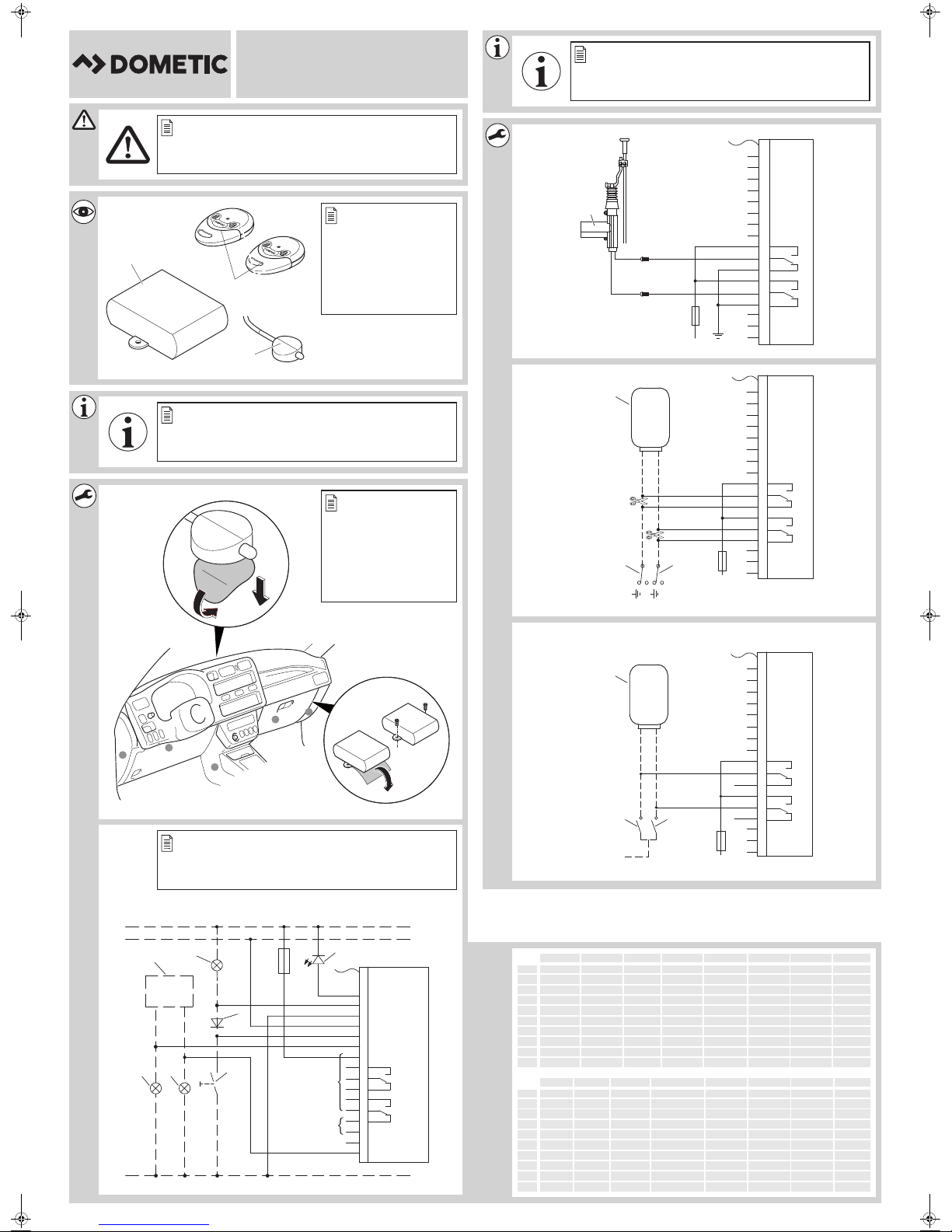
3Scope of delivery
See fig. 2
No. in
fig. 2
1 1 Controller 9101300011
2 2 Hand-held transmitter 9600000372
3 1 Status LED
– 1 Control unit connection cable
––Fastening material
Quantity Designation Item no.
4Intended use
The MagicTouch MT400 radio remote control (item no. 9600000389) supplements the central
locking system of your vehicle. You open and close the doors of your vehicle using a hand-held
transmitter.
The following can be operated by remote control using the convenience function, e. g.
• the dipped headlights can be switched on for 10 sec. (coming home function) or
• electric power windows and sliding roof can be activated
(as long as this is factory-set and operable by key).
4
Page 7

MT400 Instructions before installation
EN
5 Instructions before installation
NOTE
I
Your vehicle should meet the following requirements to be able to open and close it with
MagicTouch:
• 12 V operating voltage
• Central locking system
5.1 Setting the configuration
Clarify the following before installing and programming the system:
• Is the driver's door equipped with its own servo motor for locking?
If no: retrofit a servo motor (e. g. ML-11).
Some manufacturers equip their vehicles with a power-saving central locking system. In these
vehicles, there is no servo motor in the driver's door; there is an electrical switch instead.
If you do not have sufficient technical knowledge for installing and connecting
components in vehicles, you should have a specialist install the radio remote control in
your vehicle.
• Do the door contacts have a negative or positive charge?
The system must be programmed accordingly, see chapter “Programming MagicTouch” on
page 17.
• Is it permitted by law in your country for the warning system to flash when opening and
closing the central locking system?
The system must be programmed accordingly, see chapter “Programming MagicTouch” on
page 17.
• What should the convenience function control, e. g.:
– the dipped headlights for 10 sec. (coming home function)
In this case, clarify whether the dipped headlights are positively or negatively charged.
– electric power windows and sliding roof.
The system must be connected and set up accordingly, see chapter “Setting up the conveni-
ence function” on page 9.
Is the maximum power of 10 A sufficient?
If no, an additional relay must be used.
5
Page 8

Instructions before installation MT400
EN
• What type of switching function does the original central locking system have?
The system must be programmed accordingly, see chapter “Connecting MT400 to the central locking system” on page 8.
You will require the circuit diagram for the central locking system to do so. You can obtain this
from your vehicle dealership. There is corresponding information for some vehicle in chapter
“Vehicle-specific data” on page 9.
If no original circuit diagrams are available and you cannot find your vehicle in the table in
chapter “Vehicle-specific data” on page 9, you will need to determine the function of the
control cables that run from the control unit for the central locking system to the vehicle
doors.
NOTICE!
A
Only connect MagicTouch using the control cables for the central locking and not
using other cables.
Connection to other cables than the control cables or using an incorrect circuit plan
can lead to defects in the central locking system and the remote control.
• How long does the central locking system have to be activated for?
The activation time for MagicTouch was set to 0.7 sec. at the factory.
In some vehicles, forexample Mercedes, an activation time of 0.7 sec. might not be sufficient
to completely activate the central locking system.
To program the system to 3 sec., see chapter “Programming MagicTouch” on page 17.
5.2 Determining the installation location for the control unit
Select the installation location for the control unit:
• in the vehicle interior,
• not in areas where strong electrical fields could cause interference, e. g. ignition cables or
central control electronics,
• not in the immediate vicinity of other control units, in order to prevent the devices from
interfering with each other (which could cause malfunctions and reduce the range of the radio
remote control),
• not directly next to ventilator nozzles.
5.3 Determining the installation location for the status LED
Select a position on the dashboard.
6
Page 9
MT400 Installing MT400
EN
6 Installing MT400
See fig. 4
➤ Screw the control unit firmly to the vehicle with the screws supplied (B) or use double-sided
adhesive tape (A).
➤ Fix the status LED to the dashboard with double-sided adhesive tape.
7 Connecting MT400
7.1 Connecting MT400 to the power
See fig. 5
No. Designation
1 Indicator relay
2Interior lighting
3 Diode 1N4002
4Status LED
5 Door contact switch
6 Right-hand indicator
7Left-hand indicator
The control unit has the following connections:
Te r m i na l Connection Te r m i n a l Connection
1 Antenna 8 Left-hand indicator
2 (not assigned) 9 Battery, +12 V, terminal 30
3 Status LED 10, 11, 12 Closed
4 Interior lighting 13, 14, 15 Open
5 Earth, terminal 31 16 Convenience output
6 Ignition, +12 V, terminal 15 17 Convenience input
7 Door contact +/– 18 Right-hand indicator
7
Page 10
Connecting MT400 MT400
EN
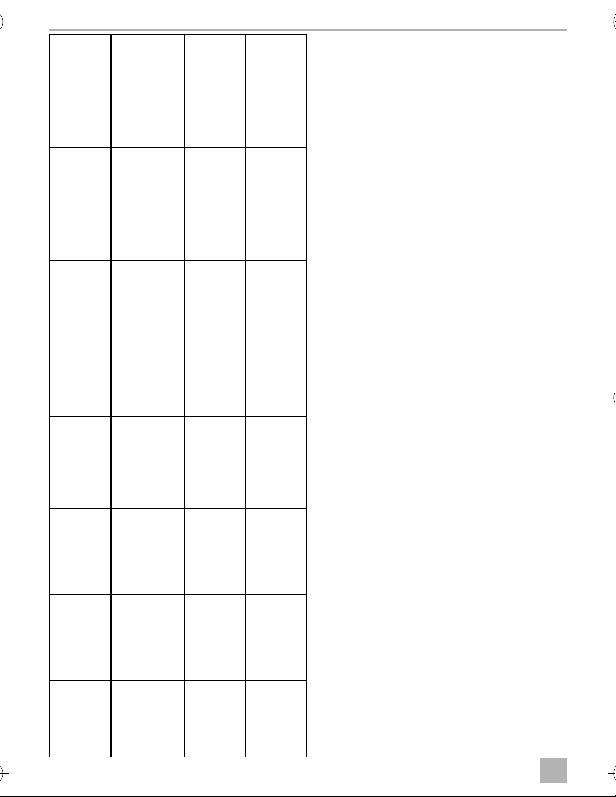
7.2 Connecting MT400 to the central locking system
➤ Connect MagicTouch in accordance with the corresponding circuit diagram (for details, see
table chapter “Keys for the circuit diagrams” on page 8):
• Vehicles without a servo motor in the driver's door (driver's door cannot be locked and
unlocked from the passenger's door) or with pressure vacuum central locking without electrical
control cable: fig. 7
In these cases, you will require an additional servo motor, type no. ML-11 for the driver's door.
• Two cables switching from negative to +12 V: fig. 8
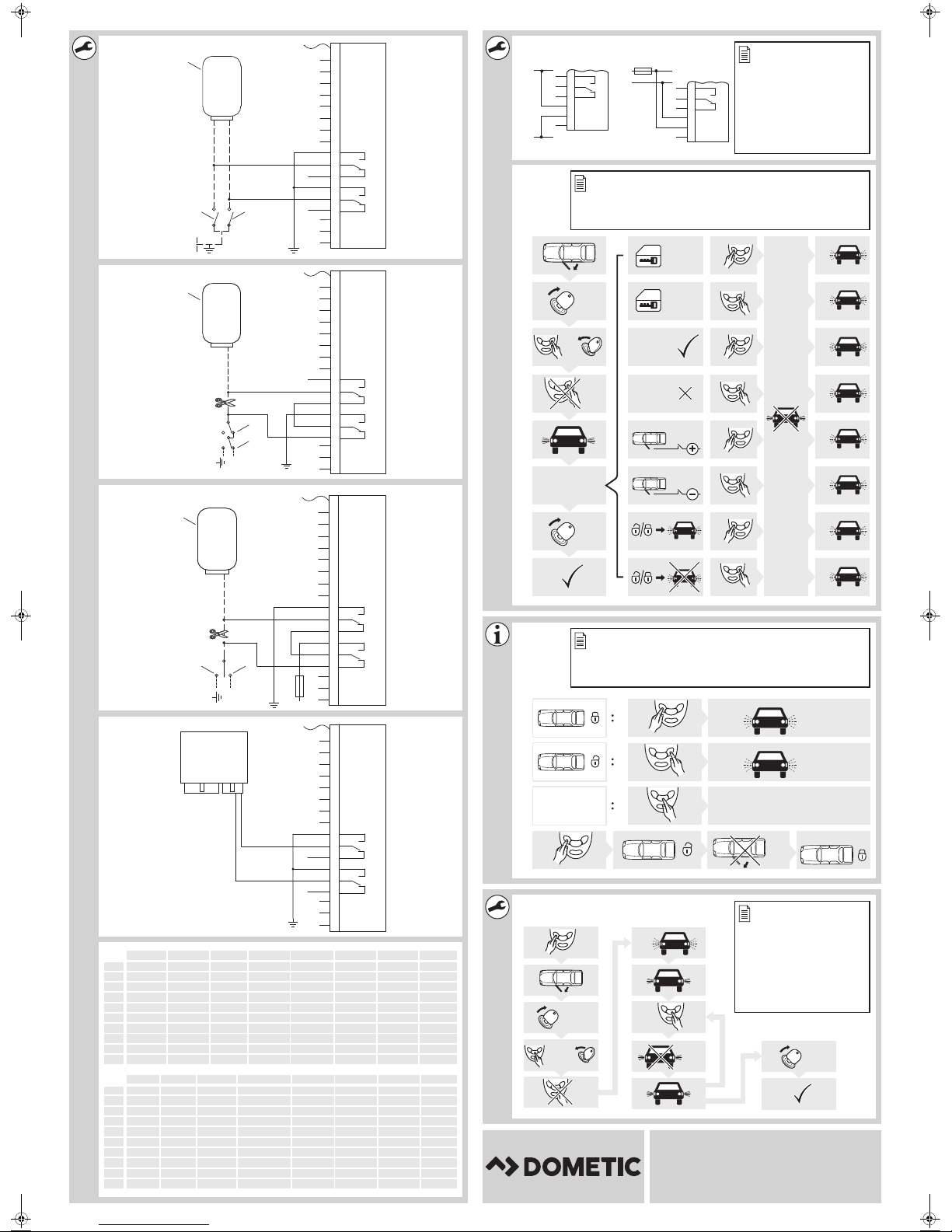
• Two +12 V pulse control cables: fig. 9
• Two negative pulse control cables: fig. 0
• One open and negative pulse control cable: fig. a
• One +12 V and negative pulse control cable: fig. b
• Connection to the central locking system ML-44(22): fig. c
NOTE
I
Keys for the circuit diagrams
No. in fig. 7
Check whether the indicators flash once upon locking with the remote control.
If they flash twice, you will need to reconnect the grey/yellow cable to pin 12 and the
blue/yellow cable to pin 13 of the control unit.
to fig. c
1 Control unit for the vehicle's own central locking system
2 Control switch (driver's door) for the original central locking system,
3 Control switch (driver's door) for the original central locking system,
Designation
central locking closed
central locking open
8
Page 11

MT400 Connecting MT400
EN
7.3 Setting up the convenience function
See fig. d
NOTICE! Risk of damage
A
You can also set the convenience function to be a “coming home function”, for example: during
locking, the dimmed headlight is switched on for 10 sec. The function has to be programmed
(chapter “Programming MagicTouch” on page 17). You can also switch the dipped headlights on
by pressing the “Comfort” button for 10 sec (factory setting). While the convenience function is
running, this can be switched off at any time by pressing the “Comfort” button again.
➤ Connect the pink cable to the original vehicle cable which originates from the light switch and
which connects the positive signal for the dipped headlights (terminal 56b, fig. d).
➤ Negatively-connected dipped headlights (fig. d A):
Connect the brown cable to the vehicle earth (Terminal 31).
The maximum output current of 10 A for the convenience function may not be
exceeded.
If you would like to activate larger consumers, you will need to use an additional relay
(operating current relay) with a recovery diode.
➤ Positively-connected dipped headlights (fig. d B):
Connect the brown cable to +12 V (Terminal 30), which must be protected with at least 10 A.
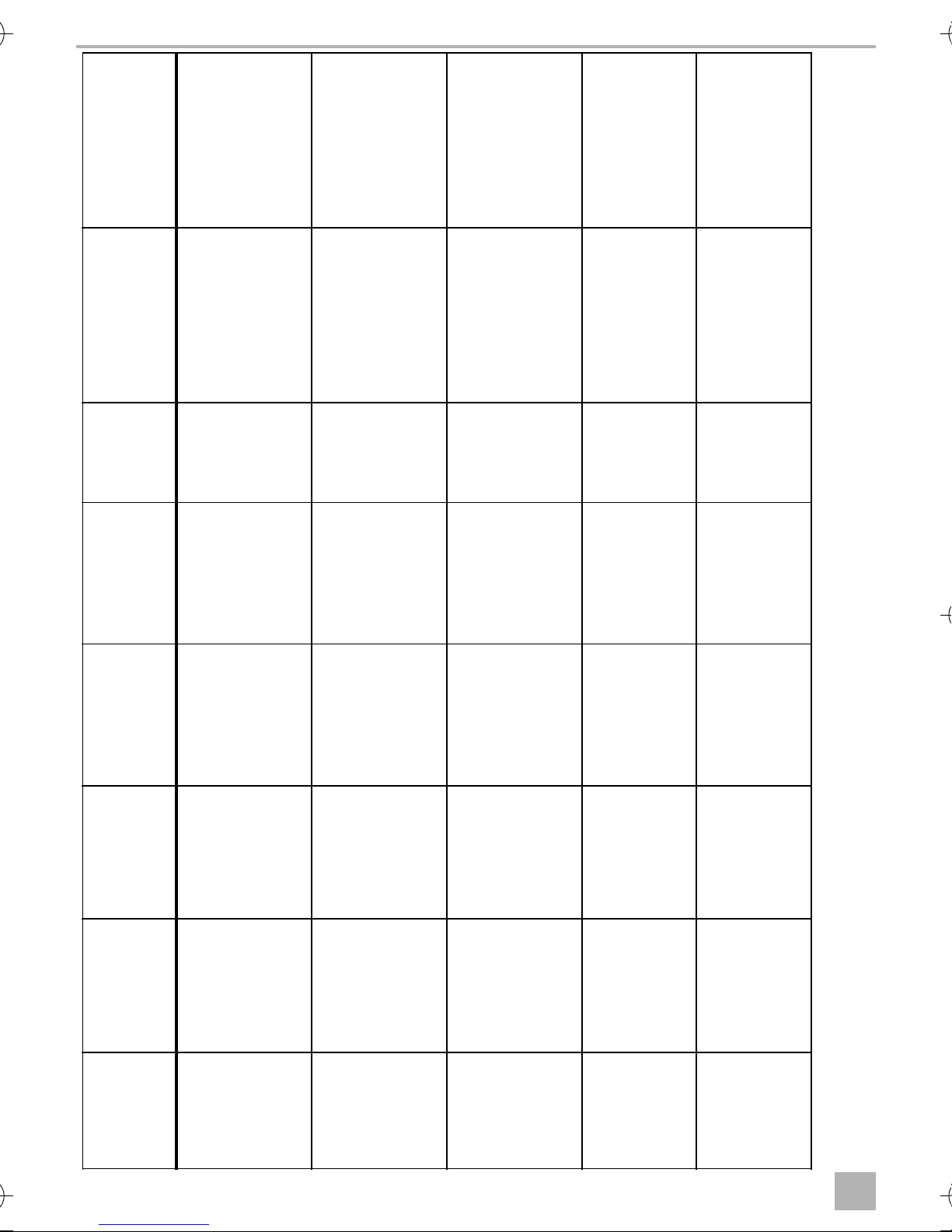
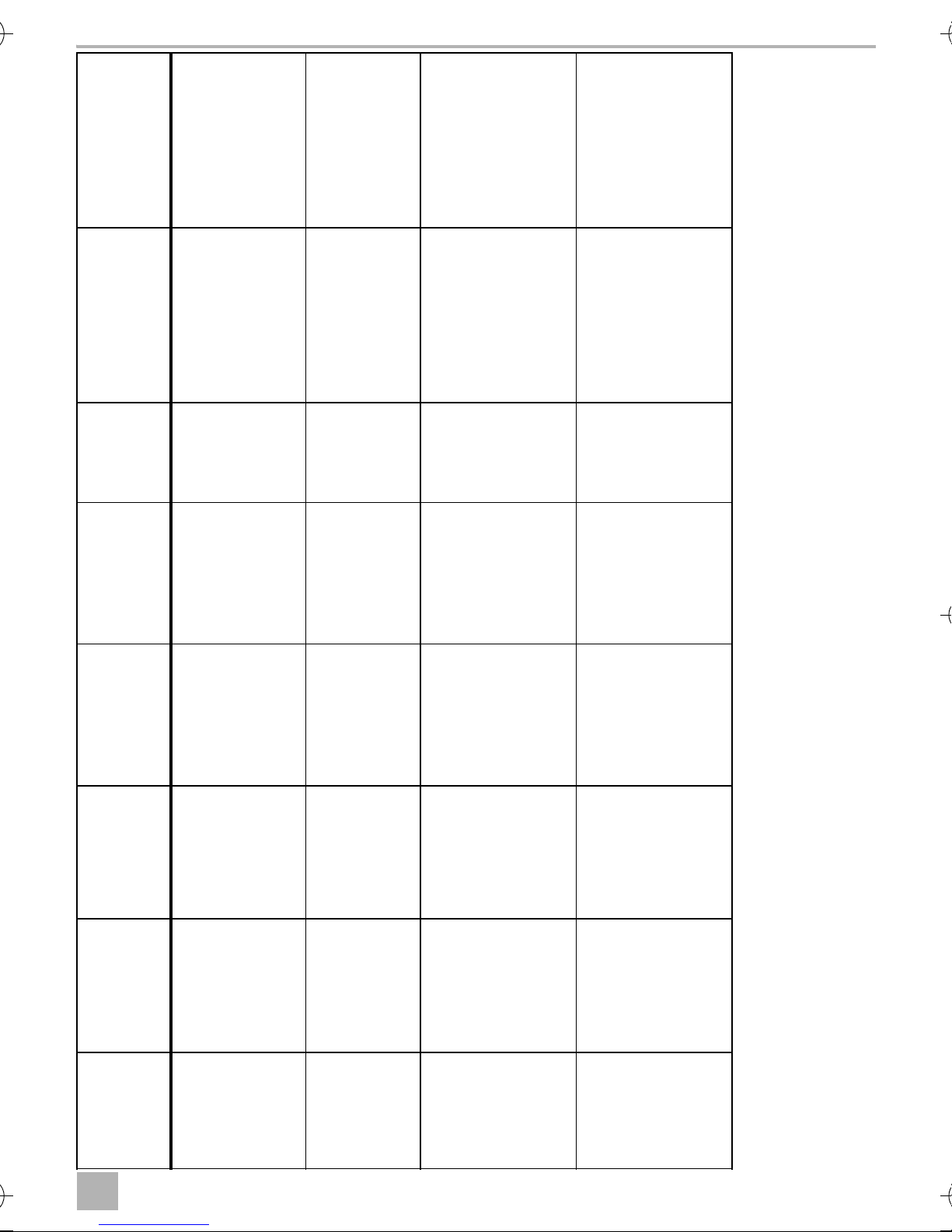
7.4 Vehicle-specific data
NOTICE! Risk of damage
A
The following table does not claim to be exhaustive. You can obtain information on other vehicles
on request from Dometic (see address on the back).
We reserve the right to make alterations.
CL = central locking
Check the polarity before connecting.
9
Page 12
Connecting MT400 MT400
EN
Door contact, cable
Circuit
CL closed,
Remarks
cable colour,
colour, position
diagram
position
connect the blue/red
control cable in the
direction of the door
and the grey/yellow
cable in the direction
of the CL-pump
door contact front left
on the A pillar, door
contact is negatively
charged
fig. b Brown/white, on the
Green/blue,
A pillar left
door contact front left
on the A pillar, door
contact is negatively
charged
fig. 0 Brown/yellow, on the
Brown/grey,
A pillar left,
coming out of
the driver's door
connect the blue/red
control cable in the
direction of the door
and the grey/yellow
cable in the direction
of the CL-pump
door contact front left
on the A pillar, door
contact is negatively
charged
fig. b Brown/yellow on the
Green/blue,
A pillar left,
coming out of
the driver's door
door contact front left
on the A pillar, door
contact is negatively
charged
fig. 0 Brown/white, on the
Brown/red or
grey,
A pillar left,
coming out of
fig. 0 Brown/white, on the
the driver's door
Brown/grey,
door contact front left
on the A pillar, door
contact is negatively
charged
A pillar left,
coming out of
the driver's door
CL open, cable
colour,
position
Green/blue,
A pillar left
Indicator
right, cable
colour,
position
Black/green,
cable strand left
on the sill
Indicator left,
cable colour,
position
Black/white,
cable strand left
on the sill
MT400--IO--16s.book Seite 10 Donnerstag, 25. August 2016 2:37 14
Veh icle
Audi 80 type
89 and B4,
constr. year:
86–94
10
Brown/green,
A pillar left,
coming out of
Black/green,
cable strand left
on the sill
Black/white,
cable strand left
on the sill
Audi 100 And
A6 type C4,
constr. year:
the driver's door
90–97 with
theft
protection
Green/blue,
A pillar left,
coming out of
Black/green,
cable strand left
on the sill
Black/white,
cable strand left
on the sill
Audi 100 And
A6 type C4,
constr. year:
the driver's door
90–97
without theft
protection
Grey/black,
A pillar left,
coming out of
the driver's door
Black/green,
cable strand left
on the sill
Black/white,
cable strand left
on the sill
Audi A3 type
8L, constr.
year: 96–01
Grey/white,
A pillar left,
coming out of
the driver's door
Black/green,
cable strand left
on the sill
Black/white,
cable strand left
on the sill
Audi A4 type
with theft
B5 constr.
year: 94–...
protection
Page 13
MT400 Connecting MT400
EN
connect the blue/red
control cable in the
direction of the door
and the grey/yellow
cable in the direction
of the CL-pump
CL control unit is on
the left side in the A
Remarks
Door contact, cable
pillar
contact front left on
the A pillar, door
contact is negatively
colour, position
charged
door contact front left
on the A pillar, door
contact is negatively
A contact pin from
BMW with the part
no. 61130005199
charged
on the door contact
front left on the B
may be required, CL
control unit is behind
the glove
compartment
A contact pin from
BMW with the part
pillar, door contact is
negatively charged
on the door contact
no. 61130005199
may be required, CL
control unit is behind
the glove
compartment
front left on the B
pillar, door contact is
negatively charged
CL closed,
CL open, cable
Indicator
Circuit
diagram
cable colour,
position
colour,
position
right, cable
colour,
fig. b Grey, on the door
Green/blue,
Green/blue,
Black/green,
position
A pillar left,
coming out of
the driver's door
A pillar left,
coming out of
the driver's door
cable strand left
on the sill
fig. 0 Brown/yellow, on the
Yellow/blue,
Green/blue,
Black/green
CL control unit
pin 7
CL control unit
pin 6
30-pin white
plug under the
fig. 9 Brown/grey/yellow,
Pin 17, yellow
26-pin plug for
the CL control
unit
Pin 4, yellow
26-pin plug for
the CL control
unit
dashboard
Blue/brown,
cable strand left
on the sill
fig. 9 Brown/grey/yellow,
Pin 24, white
26-pin plug for
the CL control
unit
Pin 25, white
26-pin plug for
the CL control
unit
Blue/brown,
cable strand left
on the sill
Black/white,
cable strand left
Indicator left,
cable colour,
position
MT400--IO--16s.book Seite 11 Donnerstag, 25. August 2016 2:37 14
Veh icle
on the sill
Audi A4 type
B5, constr.
year: 94–...
without theft
protection
Green/blue
30-pin white
plug under the
BMW 3 series
E30, constr.
year: 82–90
dashboard
Blue/green,
cable strand left
BMW 3 series
E36, constr.
on the sill
year: 91–…
Blue/green,
cable strand left
BMW 3 series
E36, constr.
on the sill
year: 91–…
11
Page 14
Connecting MT400 MT400
EN
A contact pin from
BMW with the part
no. 61131393704
may be required, CL
control unit is behind
the glove
compartment
A contact pin from
BMW with the part
no. 61131393704
may be required, CL
control unit is behind
the rear seat
A contact pin from
BMW with the part
no. 61131393704
may be required, CL
control unit is behind
Remarks
Door contact, cable
the rear seat
on the door contact
front left on the B
pillar, door contact is
colour, position
negatively charged
door contact left on
the B pillar
door contact front left
on the B pillar, door
contact is negatively
charged
connect the blue/red
control cable in the
direction of the door
and the grey/yellow
cable in the direction
of the CL-pump
door contact front left
on the A pillar, door
contact is negatively
charged
CL closed,
CL open, cable
Indicator
Circuit
diagram
cable colour,
position
colour,
position
right, cable
colour,
fig. 9 Brown/grey/yellow,
Pin 19, white
26-pin plug for
the CL control
unit
Pin 25, white
26-pin plug for
the CL control
unit
Blue/brown,
cable strand left
position
on the sill
fig. 9 Brown/violet, on the
Pin 7, yellow
26-pin plug for
the CL control
unit
Pin 16, yellow
26-pin plug for
the CL control
unit
Blue/brown,
cable strand left
on the sill
fig. 9 Brown/violet, on the
(until 9/91) Pin 1,
white 26-pin
plug for the CL
control unit
(until 9/91) Pin 2
or 6, white
26-pin plug from
CL control unit
Blue/brown,
cable strand left
on the sill
(from 9/91)
Pin 24, white
26-pin plug for
the CL control
(from 9/91)
Pin 25, white
26-pin plug for
the CL control
fig. b Brown/white, on the
unit
Blue, A pillar left,
unit
Blue, A pillar left,
Black/green,
coming out of
the driver's door
coming out of
the driver's door
cable strand left
on the sill
Blue/green,
cable strand left
MT400--IO--16s.book Seite 12 Donnerstag, 25. August 2016 2:37 14
Indicator left,
cable colour,
position
Veh icle
BMW 3 series
E36, constr.
on the sill
year: 93–…
with alarm
12
Blue/green,
cable strand left
BMW 5 series
E34, constr.
on the sill
year: 88–95
Blue/green,
cable strand left
BMW 5 series
E34, constr.
on the sill
year: 88–95
Black/white,
Mercedes
cable strand left
on the sill
190 W201,
constr. year:
…–94
Page 15
MT400 Connecting MT400
EN
connect the blue/red
control cable in the
direction of the door
and the grey/yellow
cable in the direction
contact is negatively
charged
of the CL-pump
door contact front left
on the B pillar, door
contact is negatively
charged
door contact front left
on the A pillar, door
contact is negatively
charged
contact front left on
the A pillar, door
contact is negatively
charged
contact front left on
the A pillar, door
contact is negatively
charged
Remarks
Door contact, cable
door contact front left
colour, position
on the A pillar, door
CL closed,
CL open, cable
Indicator
Circuit
diagram
cable colour,
position
colour,
position
right, cable
colour,
fig. b Brown/white, on the
Blue, A pillar left,
Blue, A pillar left,
Black/green,
position
coming out of
the driver's door
coming out of
the driver's door
cable strand left
on the sill
fig. 0 Brown/white, on the
Black, A pillar
left, coming out
of the driver's
door
Blue, A pillar left,
coming out of
the driver's door
Black/green,
cable strand left
on the sill
fig. 0 Brown/white, on the
Brown/red, A
pillar left, coming
out of the driver's
Brown/white,
A pillar left,
coming out of
Black/green,
cable strand left
on the sill
door
the driver's door
fig. 0 Grey, on the door
Brown/red, A
pillar left, coming
out of the driver's
door
Brown/white,
A pillar left,
coming out of
the driver's door
Black/green,
cable strand left
on the sill
fig. 0 Grey, on the door
Brown/red, A
pillar left, coming
out of the driver's
door
Brown/white,
A pillar left,
coming out of
the driver's door
Black/green,
cable strand left
on the sill
Black/white,
cable strand left
Mercedes
on the sill
200 W124,
constr. year:
…–95
Indicator left,
cable colour,
position
MT400--IO--16s.book Seite 13 Donnerstag, 25. August 2016 2:37 14
Veh icle
Black/white,
cable strand left
on the sill
Mercedes
C180 W202,
constr. year:
94–…
Black/white,
Opel Astra F
cable strand left
on the sill
and G,
constr. year:
92–…
Black/white,
Opel Calibra,
cable strand left
on the sill
constr. year:
90–…
Black/white,
Opel Corsa
cable strand left
on the sill
A, B, constr.
year:
93–2000
13
Page 16
Connecting MT400 MT400
EN
The door control unit
is on the window
regulator underneath
Remarks
Door contact, cable
contact front left on
the A pillar, door
contact is negatively
colour, position
charged
contact front left on
the A pillar, door
contact is negatively
charged
brown/white, on the
door contact front left
on the A pillar, door
contact is negatively
charged
door contact front left
on the A pillar, door
contact is negatively
charged
the door panel
door contact front left
on the A pillar, door
contact is negatively
charged
CL closed,
CL open, cable
Indicator
Circuit
diagram
cable colour,
position
colour,
position
right, cable
colour,
fig. 0 Green, on the door
Brown/red, A
pillar left, coming
out of the driver's
Brown/white,
A pillar left,
coming out of
Black/green,
cable strand left
position
on the sill
door
the driver's door
fig. 0 Grey, on the door
Brown/red, A
pillar left, coming
out of the driver's
door
Brown/white,
A pillar left,
coming out of
the driver's door
Black/green,
cable strand left
on the sill
fig. 0 Grey/white or
Brown/red, A
pillar left, coming
out of the driver's
Brown/white,
A pillar left,
coming out of
Black/green,
cable strand left
on the sill
door
the driver's door
fig. 9 Brown/white, on the
Grey, A pillar left,
coming out of
the driver's door
Green, A pillar
left, coming out
of the driver's
door
Black/green,
cable strand left
on the sill
fig. 0 Brown/white, on the
Yellow/blue pin
4, on the door
control unit,
driver's side
Yellow/green pin
24, on the door
control unit,
driver's side
Black/green,
cable strand left
on the sill
Black/white,
cable strand left
MT400--IO--16s.book Seite 14 Donnerstag, 25. August 2016 2:37 14
Opel Kadett
on the sill
E, constr.
year: 90–…
Indicator left,
cable colour,
position
Veh icle
Black/white,
Opel Omega
14
cable strand left
on the sill
A and B,
constr. year:
90–…
Black/white,
Opel Vectra A
cable strand left
on the sill
and B
Black/white,
VW Golf lll
cable strand left
on the sill
and Vento
type 1HXO,
Black/white,
cable strand left
on the sill
constr. year:
91–…
VW Golf lV,
constr. year:
97–… with
electric
windows
Page 17
MT400 Connecting MT400
EN
CL control unit is on
the left, next to the
steering column; the
cable colours can also
be found on the A
Remarks
Door contact, cable
pillar
control unit on pin 18,
door contact is
colour, position
negatively charged
cable duct of the A
pillar, door contact is
negatively charged
door contact front left
on the A pillar, door
contact is negatively
charged
door contact front left
on the A pillar, door
contact is negatively
Central locking is
charged
earth controlled. A
200 Ω resistor must
be inserted in the
blue/red cable, CL
control unit is in a
black box in the
driver's feet area
cable duct of the A
pillar, door contact is
negatively charged
under the carpet
CL closed,
CL open, cable
Indicator
Circuit
diagram
cable colour,
position
colour,
position
right, cable
colour,
fig. 0 Blue/grey, on the CL
Yellow/blue or
Yellow/green,
Black/green,
position
blue, CL control
unit grey 24 pin
plug underneath
the dashboard
CL control unit
grey 24 pin plug
underneath the
dashboard
cable strand left
on the sill
fig. 0 Brown/white, in the
Grey/yellow, A
pillar left, coming
out of the driver's
Blue/violet,
A pillar left,
coming out of
Black/green,
cable strand left
on the sill
fig. 9 Brown/white, on the
door
Red/yellow, A
the driver's door
Black/white,
Black/green,
pillar left, coming
out of the driver's
door
A pillar left,
coming out of
the driver's door
cable strand left
on the sill
fig. 9 Brown/white, on the
Grey, A pillar left,
coming out of
the driver's door
Green, A pillar
left, coming out
of the driver's
door
Black/green,
cable strand left
on the sill
fig. 0 Brown/white, in the
Brown/blue, pin
2 from the
original CL
Red/blue, pin 4
from the original
CL control unit
Black/green,
cable strand left
on the sill
control unit
Black/white,
cable strand left
VW Golf lV.
on the sill
constr. year:
97 –…
without
electric
windows
Indicator left,
cable colour,
position
MT400--IO--16s.book Seite 15 Donnerstag, 25. August 2016 2:37 14
Veh icle
Black/white,
VW Lupo,
cable strand left
on the sill
constr. year:
98–…
Black/white,
VW Passat
cable strand left
on the sill
35i, constr.
year: 88–92
Black/white,
VW Passat
cable strand left
on the sill
35i, constr.
year: 93–96
Black/white,
VW Passat
cable strand left
on the sill
3B, constr.
year:
9/97–…
15
Page 18
Connecting MT400 MT400
EN
Remarks
door contact front left
on the A pillar, door
contact is negatively
Door contact, cable
colour, position
charged
cable duct of the A
pillar, door contact is
negatively charged
the fuse box, door
contact is negatively
charged
CL closed,
CL open, cable
Indicator
Circuit
diagram
cable colour,
position
colour,
position
right, cable
colour,
position
fig. 9 Brown/white, on the
Grey/red, A pillar
left, coming out
of the driver's
Grey/black,
A pillar left,
coming out of
Black/green,
cable strand left
on the sill
door
the driver's door
fig. 9 Brown/white, in the
Grey, A pillar left,
coming out of
the driver's door
Green, A pillar
left, coming out
of the driver's
door
Black/green,
cable strand left
on the sill
fig. 9 Brown/white, behind
White, A pillar
left, coming out
Yellow, A pillar
left, coming out
Black/green,
cable strand left
of the driver's
door
of the driver's
door
on the sill
Black/white,
cable strand left
MT400--IO--16s.book Seite 16 Donnerstag, 25. August 2016 2:37 14
VW Polo 6N,
on the sill
constr. year:
95–…
Indicator left,
cable colour,
position
Veh icle
Black/white,
VW Sharan
16
cable strand left
on the sill
7M, constr.
year: 96–…
Black/white,
VW T4,
cable strand left
on the sill
constr. year:
93–…
Page 19
MT400 Programming MagicTouch
EN
8 Programming MagicTouch
See fig. e
8.1 Programmable functions
The standard settings are printed in bold.
Function Values Press button
Activation time for central
locking system
Convenience function activated
Control for door contact switch positive connection
Control for hazard lights system activated
3sec.
0.7 sec.
deactivated
negative connection
deactivated
8.2 Programming functions
➤ Open the vehicle door.
➤ Switch on the ignition.
➤ Press and hold the “Open” button and switch the ignition off.
➤ Let go of the button.
✓ The status LED and the hazard lights are lit continually.
✓ The system is now in programming mode.
1 x “Close” button
1 x “Open” button
2 x “Close” button
2 x “Open” button
3 x “Close” button
3 x “Open” button
4 x “Close” button
4 x “Open” button
➤ Select the corresponding setting in accordance with the table, see chapter “Programmable
functions” on page 17.
✓ The status LED and the hazard lights go out while the value is being saved.
✓ After 2 sec. you will receive a confirmation:
– After pressing the “Close” button: status LED and hazard lights flash once.
– After pressing the “Open” button: status LED and hazard lights flash twice.
✓ When the status LED and hazard lights are lit continually, the function has been programmed.
You can now program other functions or exit programming mode.
To exit programming mode:
➤ Switch on the ignition.
17
Page 20

Operating MagicTouch MT400
EN
9 Operating MagicTouch
9.1 Using the remote control
See fig. f
Observe the following instructions when you use MagicTouch:
CAUTION! Danger of crushing!
!
• To ensure the remote control functions properly, a disturbance-free connection between the
hand-held transmitter and the control unit is required.
• Depending on where the control unit is installed, and the transmission power of nearby sources
of interference, the range is up to 20m.
• Each time the hand-held transmitter is used, it sends a new code (rolling code). For this reason,
the control unit might not recognise the hand-held transmitter immediately if you use the
hand-held transmitter too frequently without the control unit receiving the transmission signal.
In this event, press the hand-held transmitter again another one to three times; after the third
attempt at the latest, the control unit will detect the hand-held transmitter again.
Never allow the electric windows to be closed while they are unattended.
To close the central locking:
➤ Press the “Close” button on the hand-held transmitter.
✓ If the ignition is switched off, the hazard light flashes once for confirmation.
✓ When set: the convenience function is activated.
✓ The interior light is switched off.
✓ The status LED starts flashing.
To open the central locking:
➤ Press the “Open” button on the hand-held transmitter.
✓ If the ignition is switched off, the hazard light flashes twice for confirmation.
✓ In vehicles with a negatively connected door contact: the interior lighting is switched on and
goes out again when the ignition is switched on.
✓ The status LED goes out.
Using the convenience function
If the vehicle is locked, pressing the middle button on the hand-held transmitter activates the
convenience output. Depending on the setting, the convenience output is connected when the
central locking is closed, or by pressing the “Comfort” button.
✓ The hazard lights flash once for confirmation.
18
Page 21

MT400 Operating MagicTouch
EN
Automatically re-locking the central locking system
If the hand-held transmitter is pressed unintentionally (central locking opens) without any door
being opened, the central locking system closes again after approx. one minute.
Safety locking
If the ignition is switched on, the central locking system can be locked using the hand-held
transmitter. In doing so, the indicators are not activated.
The central locking system can be re-opened using the hand-held transmitter or by switching off
the ignition. This function is not supported by all vehicle models.
9.2 Replacing the battery
You must replace the batteries:
• when the range of the hand-held transmitter decreases distinctly, or
• when the control LED flickers during transmission or
• when, after opening, the hazard lights flash quickly 5 times. In this case, replace the battery
within one month.
Please observe the following instructions for batteries:
WARNING!
!
• Only use leak-proof batteries that are suitable for electronic devices.
• Never attempt to do the following with batteries:
– recharge them,
–open them or
–throw them in fires.
To replace the batteries, proceed as follows:
➤ Remove the screw on the back of the hand-held transmitter and open the transmitter.
➤ Replace the battery.
Make sure that the polarity is correct when you insert the battery (battery type CR 2032 3 V).
The positive terminal is at the top.
Batteries are available e.g. in photo shops, clock shops, etc.
➤ Refit the lid on the hand-held transmitter and re-insert the screw.
Keep the batteries out of reach of children.
19
Page 22

Operating MagicTouch MT400
EN
9.3 Learning or deprogramming the hand-held transmitter
See fig. g
MagicTouch can be operated using up to 10 hand-held transmitters. If a new hand-held transmitter
is to be learned, all other transmitters will have to be paired again.
Proceed as follows for learning a new hand-held transmitter:
To switch to learning mode:
➤ Use a hand-held transmitter to open the vehicle.
➤ Take a seat in the vehicle and leave the door open.
➤ Switch on the ignition.
➤ Press and hold the “comfort” button on a hand-held transmitter already paired.
➤ Switch the ignition off.
➤ Let go of the button.
✓ The status LED and the hazard light flash 10 times, after which they are continually lit.
✓ The system is now in learning mode.
NOTE
I
Learning the hand-held transmitter
Learn all the hand-held transmitters which you would like to use during this learning phase. This
also applies for the hand-held transmitters which you have already been using!
➤ Press the “Comfort” button on the hand-held transmitter.
✓ The status LED and the hazard lights go out while the value is being saved.
✓ If the status LED and the hazard lights light up continually again after 2 sec., then the hand-held
transmitter has been paired and you can now learn the next one.
I
To exit learning mode:
If you do not press a button within 10 seconds, you will exit the learning mode.
NOTE
Only exit learning mode when you have paired all hand-held transmitters which you
wish to use. Hand-held transmitters which you do not learn during this pairing phase
will be automatically deprogrammed from the system. They can only be used again
once they have been relearned.
➤ Switch on the ignition.
Testing the hand-held transmitter
➤ Test the new hand-held transmitter.
If a hand-held transmitter does not function, then they must all be learned again.
20
Page 23

MT400 MagicTouch care and cleaning
EN
10 MagicTouch care and cleaning
NOTICE!
A
11 Guarantee
The statutory warranty period applies. If the product is defective, please contact the
manufacturer's branch in your country (see the back of the instruction manual for the addresses) or
your retailer.
For repair and guarantee processing, please send the following items:
• Defect components
• A copy of the receipt with purchasing date
• A reason for the claim or description of the fault
Do not use sharp or hard objects to clean the device as these may damage the
components.
12 Disposal
➤ Place the packaging material in the appropriate recycling waste bins wherever possible.
If you wish to finally dispose of the product, ask your local recycling centre or specialist
dealer for details about how to do this in accordance with the applicable disposal
M
B
regulations.
Protect the environment!
Do not dispose of any batteries with general household waste.
Return defective or used batteries to your retailer or dispose of them at collection points.
21
Page 24
Technical data MT400
EN
12
13 Technical data
Central locking switching current: max. 10 A
Indicator activation switching current: max. 2 x 5 A
Interior light switching current: max. 1 A
Convenience output switching current: max. 10 A
Central locking control time: optionally 0.7 s/3.0 s
Indicator control time (On/Off): 1 x 2 s/2 x 0.75 s
Controller
Operating voltage: 9–15 Vg
Standby current consumption without LED: approx. 3 mA
Standby current consumption with LED: approx. 8 mA
Operating temperature: –40 °C to +85 °C
Dimensions (L x W x H): 86 x 74 x 24 mm
Hand-held transmitter
Frequency: 433.92 MHz
Range: 10 m–20 m
Battery type: CR2032, 3 V
Operating temperature: –20 °C to +60 °C
Dimensions (L x W x H): 54 x 39 x 12 mm
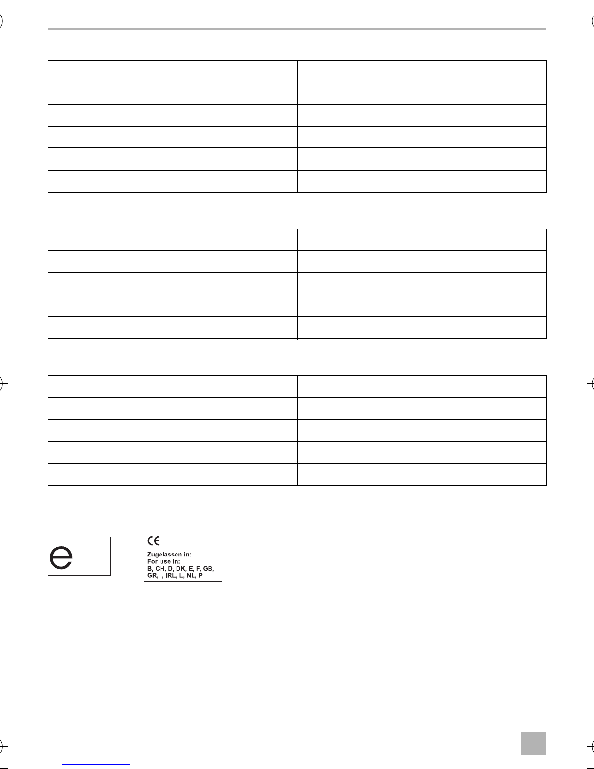
Certifications
The device has e12 certification and R&TTE certification.
22
Page 25
MT400 Erklärung der Symbole
DE
Bitte lesen Sie diese Anleitung vor Einbau und Inbetriebnahme sorgfältig durch und
bewahren Sie sie auf. Geben Sie sie im Falle einer Weitergabe des Produktes an den
Nutzer weiter.
Inhaltsverzeichnis
1 Erklärung der Symbole. . . . . . . . . . . . . . . . . . . . . . . . . . . . . . . . . . . . . . . . . . . . . . . . . . . . . .23
2 Sicherheits- und Einbauhinweise. . . . . . . . . . . . . . . . . . . . . . . . . . . . . . . . . . . . . . . . . . . . . .24
3 Lieferumfang . . . . . . . . . . . . . . . . . . . . . . . . . . . . . . . . . . . . . . . . . . . . . . . . . . . . . . . . . . . . . .24
4 Bestimmungsgemäßer Gebrauch . . . . . . . . . . . . . . . . . . . . . . . . . . . . . . . . . . . . . . . . . . . . .24
5 Hinweise vor dem Einbau . . . . . . . . . . . . . . . . . . . . . . . . . . . . . . . . . . . . . . . . . . . . . . . . . . .25
6 MT400 montieren. . . . . . . . . . . . . . . . . . . . . . . . . . . . . . . . . . . . . . . . . . . . . . . . . . . . . . . . . .27
7 MT400 Anschließen . . . . . . . . . . . . . . . . . . . . . . . . . . . . . . . . . . . . . . . . . . . . . . . . . . . . . . . .27
8 MagicTouch programmieren. . . . . . . . . . . . . . . . . . . . . . . . . . . . . . . . . . . . . . . . . . . . . . . . .37
9 MagicTouch bedienen. . . . . . . . . . . . . . . . . . . . . . . . . . . . . . . . . . . . . . . . . . . . . . . . . . . . . .38
10 MagicTouch pflegen und reinigen . . . . . . . . . . . . . . . . . . . . . . . . . . . . . . . . . . . . . . . . . . . . 41
11 Gewährleistung . . . . . . . . . . . . . . . . . . . . . . . . . . . . . . . . . . . . . . . . . . . . . . . . . . . . . . . . . . . 41
12 Entsorgung . . . . . . . . . . . . . . . . . . . . . . . . . . . . . . . . . . . . . . . . . . . . . . . . . . . . . . . . . . . . . . . 41
13 Technische Daten . . . . . . . . . . . . . . . . . . . . . . . . . . . . . . . . . . . . . . . . . . . . . . . . . . . . . . . . . .42
1 Erklärung der Symbole
WARNUNG!
!
!
A
Sicherheitshinweis: Nichtbeachtung kann zu Tod oder schwerer Verletzung führen.
VORSICHT!
Sicherheitshinweis: Nichtbeachtung kann zu Verletzungen führen.
ACHTUNG!
Nichtbeachtung kann zu Materialschäden führen und die Funktion des Produktes
beeinträchtigen.
HINWEIS
I
Ergänzende Informationen zur Bedienung des Produktes.
23
Page 26

Sicherheits- und Einbauhinweise MT400
DE
2 Sicherheits- und Einbauhinweise
Beachten Sie die vom Fahrzeughersteller und vom Kfz-Handwerk vorgeschriebenen
Sicherheitshinweise und Auflagen!
Der Hersteller übernimmt in folgenden Fällen keine Haftung für Schäden:
• Beschädigungen am Produkt durch mechanische Einflüsse und Überspannungen
• Veränderungen am Produkt ohne ausdrückliche Genehmigung vom Hersteller
• Verwendung für andere als die in der Anleitung beschriebenen Zwecke
3Lieferumfang
Siehe Abb. 2
Nr. in
Abb. 2
1 1 Steuergerät 9101300011
2 2 Handsender 9600000372
31Status-LED
– 1 Anschlusskabel Steuergerät
––Befestigungsmaterial
Menge Bezeichnung Artikel-Nr.
4 Bestimmungsgemäßer Gebrauch
Die Funk-Fernbedienung MagicTouch MT400 (Art.-Nr. 9600000389) ist eine Ergänzung zu der
Zentralverriegelung Ihres Fahrzeugs. Mit einem Handsender öffnen und schließen Sie die Türen
Ihres Fahrzeugs.
Mit der Komfortfunktion kann folgendes ferngesteuert werden, z B.:
• Abblendlicht für 10 s einschalten (Coming-Home-Funktion) oder
• elektrisch angetriebene Fenster und Schiebedach ansteuern
(sofern ab Werk vorgesehen und per Schlüssel bedienbar).
24
Page 27

MT400 Hinweise vor dem Einbau
DE
5 Hinweise vor dem Einbau
HINWEIS
I
Folgende Voraussetzungen muss Ihr Fahrzeug erfüllen, damit Sie es mit MagicTouch öffnen und
schließen können:
• 12-V-Betriebsspannung
• Zentralverriegelung
5.1 Konfiguration festlegen
Klären Sie vor Einbau und Programmierung der Anlage folgendes:
• Ist die Fahrertür mit einem eigenen Stellmotor für die Verriegelung ausgerüstet?
Falls nein: Rüsten Sie einen Stellmotor nach (z. B. ML-11).
Einige Hersteller rüsten ihre Fahrzeuge mit einer Spar-Zentralverriegelung aus. In diesen Fahrzeugen befindet sich in der Fahrertür kein Stellmotor, sondern nur ein elektrischer Schalter.
Wenn Sie nicht über ausreichende technische Kenntnisse für das Einbauen und
Anschließen von Komponenten in Fahrzeugen verfügen, sollten Sie sich die
Funk-Fernbedienung von einem Fachmann ins Fahrzeug einbauen lassen.
• Sind die Türkontakte minus- oder plusgeschaltet?
Das System muss entsprechend programmiert werden, siehe Kapitel „MagicTouch programmieren“ auf Seite 37.
• Ist es in Ihrem Land gesetzlich erlaubt, dass die Warnanlage beim Öffnen und Schließen
der Zentralverriegelung blinkt?
Das System muss entsprechend programmiert werden, siehe Kapitel „MagicTouch programmieren“ auf Seite 37.
• Was soll die Komfortfunktion ansteuern, z. B.:
– Abblendlicht für 10 s (Coming-Home-Funktion)
Klären Sie in diesem Fall, ob das Abblendlicht positiv oder negativ geschaltet ist.
– elektrisch angetriebene Fenster und Schiebedach
Das System muss entsprechend angeschlossen und eingerichtet werden, siehe Kapitel „Kom-
fort-Funktion einrichten“ auf Seite 29.
Reicht der maximale Strom von 10 A dafür aus?
Falls nein, muss ein Zusatzrelais verwendet werden.
25
Page 28

Hinweise vor dem Einbau MT400
DE
• Wie ist die Schaltfunktion der originalen Zentralverriegelung?
Das System muss entsprechend angeschlossen werden, siehe Kapitel „MT400 An die Zentralverriegelung anschließen“ auf Seite 28.
Hierzu benötigen Sie den Schaltplan der Zentralverriegelung, den Sie bei Ihrem Fahrzeughändler erhalten. Im Kapitel „Fahrzeugspezifische Angaben“ auf Seite 29 finden Sie zu
einigen Fahrzeugen die entsprechenden Angaben.
Wenn keine Originalschaltpläne zur Verfügung stehen und Sie in der Tabelle im Kapitel „Fahrzeugspezifische Angaben“ auf Seite 29 Ihr Fahrzeug nicht finden, müssen Sie die Funktion
der Steuerleitungen, die von dem Steuergerät der Zentralverriegelung zu der Fahrzeugtür
verlaufen, ausmessen.
ACHTUNG!
A
Schießen Sie MagicTouch nur über die Steuerleitungen der Zentralverriegelung und
nicht über andere Leitungen an.
Der Anschluss an andere Leitungen als die Steuerleitungen oder die Verwendung
eines falschen Schaltplans kann zum Defekt der Zentralverriegelung und der
Fernbedienung führen.
• Wie lange muss die Zentralverriegelung angesteuert werden?
Die Ansteuerungszeit von MagicTouch ist werkseitig auf 0,7 s eingestellt.
Bei einigen Fahrzeugen, z. B. Mercedes, kann es sein, dass die Ansteuerungszeit von 0,7 s
nicht ausreicht, um die Zentralverriegelung voll anzusteuern.
Programmieren Sie das System auf 3 s, siehe Kapitel „MagicTouch programmieren“ auf
Seite 37.
5.2 Einbauort für das Steuergerät festlegen
Wählen Sie den Einbauort für das Steuergerät:
• im Fahrgastinnenraum,
• nicht im Einflussbereich starker elektrischer Felder, z. B. Zündleitungen oder Zentral-
steuerelektronik,
• nicht direkt neben anderen Steuergeräten, um gegenseitige Störungen der Geräte zu
verhindern (dadurch können Fehlfunktionen auftreten, und die Reichweite der
Funk-Fernbedienung kann vermindert werden)
• nicht direkt an Luftaustrittsdüsen.
5.3 Einbauort für die Status-LED festlegen
Wählen Sie einen Platz auf dem Armaturenbrett.
26
Page 29
MT400 MT400 montieren
DE
6 MT400 montieren
Siehe Abb. 4
➤ Schrauben Sie das Steuergerät mit den beiliegenden Schrauben fest (B) oder verwenden Sie
doppelseitiges Klebeband (A).
➤ Befestigen Sie die Status-LED mit doppelseitigem Klebeband am Armaturenbrett.
7 MT400 Anschließen
7.1 MT400 elektrisch anschließen
Siehe Abb. 5
Nr. Bezeichnung
1 Blinkerrelais
2 Innenraumleuchte
3 Diode 1N4002 (muss eingesetzt werden, wenn die Innenraumleuchte beim Öffnen
des Fahrzeugs mit dem Schlüssel eingeschaltet wird)
4Status-LED
5 Türkontaktschalter
6Blinker rechts
7Blinker links
Das Steuergerät ist wie folgt beschaltet:
Klemme Beschaltung Klemme Beschaltung
1 Antenne 8 Blinker links
2 (nicht belegt) 9 Batterie, +12 V, Klemme 30
3 Status-LED 10, 11, 12 Zu
4 Innenraumleuchte 13, 14, 15 Auf
5 Masse, Klemme 31 16 Komfort Ausgang
6 Zündung, +12 V, Klemme 15 17 Komfort Eingang
7 Türkontakt +/– 18 Blinker rechts
27
Page 30

MT400 Anschließen MT400
DE
7.2 MT400 An die Zentralverriegelung anschließen
➤ Schließen Sie MagicTouch gemäß passendem Schaltplan an (Erklärung siehe Tabelle Kapitel
„Legende zu den Schaltplänen“ auf Seite 28):
• Fahrzeuge ohne Stellmotor in der Fahrertür (Fahrertür lässt sich nicht von der Beifahrertür aus
ver- und entriegeln) oder für Unterdruck-Zentralverriegelungen ohne elektrische Steuerleitung:
Abb. 7
Hierfür benötigen Sie zusätzlich den Stellmotor Art.-Nr. ML-11 für die Fahrertür.
• Zwei von minus auf +12 V schaltende Leitungen: Abb. 8
• Zwei +12 V impulssteuernde Leitungen: Abb. 9
• Zwei minusimpulssteuernde Leitungen: Abb. 0
• Eine offen und minusimpulssteuernde Leitung: Abb. a
• Eine +12 V und minusimpulssteuernde Leitung: Abb. b
• Anschluss an Zentralverriegelung ML-44(22): Abb. c
HINWEIS
I
Legende zu den Schaltplänen
Nr. in Abb. 7
bis Abb. c
Kontrollieren Sie, ob die Blinkleuchten beim Schließen mit der Fernbedienung einmal
blinken.
Wenn sie zweimal blinken, müssen Sie das grau/gelbe Kabel auf Pin 12 und das
blau/gelbe Kabel auf Pin 13 des Steuergerätes tauschen.
Bezeichnung
1 Steuergerät der fahrzeugeigenen Zentralverriegelung
2 Steuerschalter (Fahrzeugtür) der Original-Zentralverriegelung,
Zentralverriegelung zu
3 Steuerschalter (Fahrzeugtür) der Original-Zentralverriegelung,
Zentralverriegelung auf
28
Page 31

MT400 MT400 Anschließen
DE
7.3 Komfort-Funktion einrichten
Siehe Abb. d
ACHTUNG! Beschädigungsgefahr!
A
Sie können die Komfortfunktion z. B. als „Coming-Home-Funktion“ einrichten: beim Schließvorgang wird das Abblendlicht für 10 s eingeschaltet. Diese Funktion muss programmiert werden
(Kapitel „MagicTouch programmieren“ auf Seite 37). Außerdem können Sie das Abblendlicht
durch Drücken der Taste „Comfort“ für 10 s einschalten (Werkseinstellung). Während der Laufzeit
der Komfortfunktion kann diese durch erneutes Drücken der Taste „Comfort“ jederzeit ausgeschaltet werden.
➤ Schließen Sie die pinke Leitung an die Original-Leitung des Fahrzeugs an, die vom Licht-
schalter kommt und das Plus-Signal des Ablendlichts schaltet (Klemme 56b, Abb. d).
➤ Negativ geschaltetes Abblendlicht (Abb. d A):
Schließen Sie die braune Leitung an die Fahrzeugmasse (Klemme 31) an.
Der maximale Ausgangsstrom für die Komfortfunktion darf 10 A nicht übersteigen.
Wenn Sie größere Verbraucher ansteuern möchten, müssen Sie ein Zusatzrelais
(Arbeitsstromrelais) mit einer Freilaufdiode einsetzen.
➤ Positiv geschaltetes Abblendlicht (Abb. d B):
Schließen Sie die braune Leitung an +12 V (Klemme 30) an, die mit mindestens 10 A
abgesichert sein muss.
7.4 Fahrzeugspezifische Angaben
ACHTUNG! Beschädigungsgefahr
A
Die folgende Tabelle erhebt keinen Anspruch auf Vollständigkeit. Informationen über weitere
Fahrzeuge erhalten Sie auf Anfrage bei Dometic (Adresse siehe Rückseite).
ZV = Zentralverriegelung
Prüfen Sie vor dem Anschluss die Polarität.
29
Page 32

MT400 Anschließen MT400
DE
Anmerkung
Türkontakt Kabel-
Schalt-
ZV zu, Kabel-
farbe, Position
plan
farbe, Position
blau/rote Steuer-
Abb. b braun/weiß, am Tür-
grün/blau,
grau/gelbe Leitung
leitung Richtung Tür–
kontakt vorne links an
der A-Säule, Tür-
A-Säule links
Richtung ZV-Pumpe
anschließen
kontakt ist minus
geschaltet
Abb. 0 braun/gelb, am Tür-
braun/grau,
kontakt vorne links an
A-Säule links, aus
der A-Säule, Tür-
kontakt ist minus
geschaltet.
der Fahrertür
kommend
blau/rote Steuer-
leitung Richtung Tür–
kontakt vorne links an
Abb. b braun/gelb am Tür-
grün/blau,
A-Säule links, aus
grau/gelbe Leitung
Richtung ZV-Pumpe
anschließen
der A-Säule, Tür-
kontakt ist minus
geschaltet
der Fahrertür
kommend
kontakt vorne links an
der A-Säule, Tür-
kontakt ist minus
geschaltet.
Abb. 0 braun/weiß, am Tür-
braun/rot oder
grau, A-Säule
links, aus der
Fahrertür
kommend
Abb. 0 braun/weiß, am Tür-
braun/grau,
kontakt vorne links an
der A-Säule, Tür-
A-Säule links, aus
der Fahrertür
blau/rote Steuer-
leitung Richtung Tür–
kontakt ist minus
geschaltet
kommend
vorne links an der
Abb. b grau, am Türkontakt
grün/blau,
A-Säule links, aus
grau/gelbe Leitung
Richtung ZV-Pumpe
A-Säule, Türkontakt ist
minus geschaltet
der Fahrertür
kommend
anschließen
MT400--IO--16s.book Seite 30 Donnerstag, 25. August 2016 2:37 14
30
ZV auf, Kabel-
farbe, Position
Blinker rechts,
Kabelfarbe,
Blinker links,
Kabelfarbe,
Fahrzeug
grün/blau,
Position
schwarz/grün,
Position
schwarz/weiß,
Audi 80 Typ
A-Säule links
Kabelstrang links
am Schweller
Kabelstrang links
am Schweller
89 und B4,
Baujahr:
86–94
braun/grün,
A-Säule links, aus
der Fahrertür
kommend
schwarz/grün,
Kabelstrang links
am Schweller
schwarz/weiß,
Kabelstrang links
am Schweller
Audi 100
und A6 Typ
C4, Bau-
jahr: 90–97
grün/blau,
schwarz/grün,
schwarz/weiß,
mit DWA
Audi 100
A-Säule links, aus
der Fahrertür
Kabelstrang links
am Schweller
Kabelstrang links
am Schweller
und A6 Typ
C4, Bau-
kommend
jahr: 90–97
grau/schwarz,
schwarz/grün,
schwarzweiß,
ohne DWA
Audi A3 Typ
A-Säule links, aus
der Fahrertür
kommend
Kabelstrang links
am Schweller
Kabelstrang links
am Schweller
8L, Baujahr:
96–01
grau/weiß,
A-Säule links, aus
der Fahrertür
kommend
schwarz/grün,
Kabelstrang links
am Schweller
schwarz/weiß,
Kabelstrang links
am Schweller
Audi A4 Typ
B5 Baujahr:
94–mit
DWA
grün/blau,
A-Säule links, aus
der Fahrertür
kommend
schwarz/grün,
Kabelstrang links
am Schweller
schwarz/weiß,
Kabelstrang links
am Schweller
Audi A4 Typ
B5, Baujahr:
94–… ohne
DWA
Page 33

MT400 MT400 Anschließen
DE
ZV-Steuergerät
befindet sich auf der
linken Seite in der
Anmerkung
Türkontakt Kabel-
farbe, Position
kontakt vorne links an
der A-Säule, Tür-
A-Säule
kontakt ist minus
Evtl. werden Kontakt-
geschaltet
stifte von BMW mit
der Teile-Nr.
61130005199
Türkontakt vorne links
an der B-Säule, Tür-
kontakt ist minus
benötigt, ZV-Steuer-
gerät befindet sich
hinter dem Hand-
schuhfach
geschaltet
Evtl. werden Kontakt-
stifte von BMW mit
der Teile-Nr.
61130005199
Türkontakt vorne links
an der B-Säule, Tür-
kontakt ist minus
benötigt, ZV-Steuer-
gerät befindet sich
hinter dem Hand-
schuhfach
geschaltet
Evtl. werden Kontakt-
stifte von BMW mit
der Teile-Nr.
61131393704
Tür-kontakt vorne links
an der B-Säule, Tür-
kontakt ist minus
benötigt, ZV-Steuer-
gerät befindet sich
hinter dem Hand-
schuhfach
geschaltet
Schalt-
plan
ZV zu, Kabel-
farbe, Position
ZV auf, Kabel-
farbe, Position
Blinker rechts,
Kabelfarbe,
Abb. 0 braun/gelb, am Tür-
gelb/blau,
grün/blau,
schwarz/grün,
Position
ZV-Steuergerät
ZV-Steuergerät
30-poliger
Pin 7
Pin 6
weißer Stecker
Abb. 9 braun/grau/gelb, am
Pin 17, gelber
26-pol. Stecker
vom
ZV-Steuergerät
Pin 4, gelber
26-pol. Stecker
vom
ZV-Steuergerät
unter dem
Armaturenbrett
blau/braun,
Kabelstrang links
am Schweller
Abb. 9 braun/grau/gelb, am
Pin 24, weißer
Pin 25, weißer
blau/braun,
26-pol. Stecker
vom
26-pol. Stecker
vom
Kabelstrang links
am Schweller
ZV-Steuergerät
ZV-Steuergerät
Abb. 9 braun/grau/gelb, am
Pin 19, weißer
Pin 25, weißer
blau/braun,
26-pol. Stecker
vom
26-pol. Stecker
vom
Kabelstrang links
am Schweller
ZV-Steuergerät
ZV-Steuergerät
grün/blau,
30-poliger
weißer Stecker
unter dem
Armaturenbrett
blau/grün,
Blinker links,
Kabelfarbe,
Position
BMW 3er
E30,
Baujahr:
MT400--IO--16s.book Seite 31 Donnerstag, 25. August 2016 2:37 14
Fahrzeug
82–90
Kabelstrang links
BMW 3er
E36,
am Schweller
Baujahr:
91–…
blau/grün,
Kabelstrang links
am Schweller
BMW 3er
E36,
Baujahr:
91–…
blau/grün,
Kabelstrang links
am Schweller
BMW 3er
E36,
Baujahr:
93–…
mit Alarm
31
Page 34

MT400 Anschließen MT400
DE
Evtl. werden Kontakt-
stifte von BMW mit
der Teile-Nr.
61131393704
benötigt, ZV-Steuer-
gerät befindet sich
unter der Rücksitz-
bank
Evtl. werden Kontakt-
stifte von BMW mit
der Teile-Nr.
61131393704
benötigt, ZV-Steuer-
gerät befindet sich
unter der Rücksitz-
Anmerkung
Türkontakt Kabel-
farbe, Position
kontakt vorne links an
der B-Säule
kontakt vorne links an
der B-Säule, Tür-
kontakt ist minus
geschaltet
bank
blau/rote Steuer-
leitung Richtung Tür u.
kontakt vorne links an
die grau/gelbe
Leitung Richtung
ZV-Pumpe
der A-Säule, Tür-
kontakt ist minus
geschaltet
anschließen
blau/rote Steuer-
leitung Richtung Tür u.
kontakt vorne links an
die grau/gelbe
Leitung Richtung
ZV-Pumpe
der A-Säule, Tür-
kontakt ist minus
geschaltet
anschließen
Schalt-
plan
ZV zu, Kabel-
farbe, Position
ZV auf, Kabel-
farbe, Position
Blinker rechts,
Kabelfarbe,
Position
Abb. 9 braun/violett, am Tür-
Pin 7, gelber
26-pol. Stecker
vom
Pin 16, gelber
26-pol. Stecker
vom
blau/braun,
Kabelstrang links
am Schweller
ZV-Steuergerät
ZV-Steuergerät
Abb. 9 braun/violett, am Tür-
(bis 9/91) Pin 1,
(bis 9/91) Pin 2
blau/braun,
weißer 26-pol.
Stecker vom
oder 6, weißer
26-pol. Stecker
Kabelstrang links
am Schweller
ZV-Steuergerät
vom
ZV-Steuergerät
(ab 9/91) Pin 24,
weißer 26-pol.
(ab 9/91) Pin 25,
Abb. b braun/weiß, am Tür-
Stecker vom
ZV-Steuergerät
weißer 26-pol.
Stecker vom
blau, A-Säule
ZV-Steuergerät
blau, A-Säule
schwarz/grün,
links, aus der
Fahrertür
kommend
links, aus der
Fahrertür
kommend
Kabelstrang links
am Schweller
Abb. b braun/weiß, am Tür-
blau, A-Säule
links, aus der
Fahrertür
kommend
blau, A-Säule
links, aus der
Fahrertür
kommend
schwarz/grün,
Kabelstrang links
am Schweller
blau/grün,
Kabelstrang links
am Schweller
BMW 5er
E34,
Baujahr:
88–95
MT400--IO--16s.book Seite 32 Donnerstag, 25. August 2016 2:37 14
Blinker links,
Kabelfarbe,
Position
Fahrzeug
32
blau/grün,
Kabelstrang links
am Schweller
BMW 5er
E34,
Baujahr:
88–95
schwarz/weiß,
Mercedes
Kabelstrang links
am Schweller
190 W201,
Baujahr:
schwarz/weiß,
Kabelstrang links
am Schweller
…–94
Mercedes
200 W124,
Baujahr:
…–95
Page 35

MT400 MT400 Anschließen
DE
Anmerkung
kontakt vorne links an
der B-Säule, Tür-
kontakt ist minus
Türkontakt Kabel-
farbe, Position
geschaltet
kontakt vorne links an
der A-Säule, Tür-
kontakt ist minus
geschaltet
vorne links an der
A-Säule, Türkontakt ist
minus geschaltet
vorne links an der
A-Säule, Türkontakt ist
minus geschaltet
vorne links an der
A-Säule, Türkontakt ist
minus geschaltet
vorne links an der
A-Säule, Türkontakt ist
minus geschaltet
Schalt-
plan
ZV zu, Kabel-
farbe, Position
ZV auf, Kabel-
farbe, Position
Blinker rechts,
Kabelfarbe,
Abb. 0 braun/weiß, am Tür-
schwarz, A-Säule
blau, A-Säule
schwarz/grün,
Position
links, aus der
Fahrertür
kommend
links, aus der
Fahrertür
kommend
Kabelstrang links
am Schweller
Abb. 0 braun/weiß, am Tür-
braun/rot,
A-Säule links, aus
der Fahrertür
kommend
braun/weiß,
A-Säule links, aus
der Fahrertür
kommend
schwarz/grün,
Kabelstrang links
am Schweller
Abb. 0 grau, am Türkontakt
braun/rot,
A-Säule links, aus
der Fahrertür
kommend
braun/weiß,
A-Säule links, aus
der Fahrertür
kommend
schwarz/grün,
Kabelstrang links
am Schweller
Abb. 0 grau, am Türkontakt
braun/rot,
A-Säule links, aus
der Fahrertür
kommend
braun/weiß,
A-Säule links, aus
der Fahrertür
kommend
schwarz/grün,
Kabelstrang links
am Schweller
Abb. 0 grün, am Türkontakt
braun/rot,
A-Säule links, aus
der Fahrertür
kommend
braun/weiß,
A-Säule links, aus
der Fahrertür
kommend
schwarz/grün,
Kabelstrang links
am Schweller
Abb. 0 grau, am Türkontakt
braun/rot,
A-Säule links, aus
der Fahrertür
kommend
braun/weiß,
A-Säule links, aus
der Fahrertür
kommend
schwarz/grün,
Kabelstrang links
am Schweller
schwarz/weiß,
Kabelstrang links
Mercedes
am Schweller
C180
W202,
Baujahr:
Blinker links,
Kabelfarbe,
Position
MT400--IO--16s.book Seite 33 Donnerstag, 25. August 2016 2:37 14
Fahrzeug
94–…
schwarz/weiß,
Opel Astra F
Kabelstrang links
und G,
am Schweller
Baujahr:
92–…
schwarz/weiß,
Kabelstrang links
Opel
Calibra,
am Schweller
Baujahr:
90–…
schwarz/weiß,
Kabelstrang links
am Schweller
Opel Corsa
A, B Baujahr:
93–2000
schwarz/weiß,
Kabelstrang links
am Schweller
Opel Kadett
E, Baujahr:
90–…
schwarz/weiß,
Kabelstrang links
Opel
Omega A
am Schweller
und B,
Baujahr:
90–…
33
Page 36

MT400 Anschließen MT400
DE
Das Türsteuergerät
befindet sich am
Fensterheber
unterhalb der
Anmerkung
Türkontakt Kabel-
farbe, Position
braun/weiß, am Tür-
kontakt vorne links an
der A-Säule, Tür-
kontakt ist minus
geschaltet
kontakt vorne links an
der A-Säule, Tür-
kontakt ist minus
geschaltet
kontakt vorne links an
der A-Säule, Tür-
Türverkleidung
kontakt ist minus
geschaltet
ZV-Steuergerät ist
links neben der Lenk-
ZV-Steuergerät auf
säule; die Kabelfarben
findet man auch in der
A-Säule
Pin 18, Türkontakt ist
minus geschaltet
Kabeldurchführung an
der A-Säule, Tür-
kontakt ist minus
geschaltet
Schalt-
plan
ZV zu, Kabel-
farbe, Position
ZV auf, Kabel-
farbe, Position
Blinker rechts,
Kabelfarbe,
Abb. 0 grau/weiß oder
braun/rot,
braun/weiß,
schwarz/grün,
Position
A-Säule links, aus
der Fahrertür
A-Säule links, aus
der Fahrertür
Kabelstrang links
am Schweller
kommend
kommend
Abb. 9 braun/weiß, am Tür-
grau, A-Säule
links, aus der
Fahrertür
kommend
grün, A-Säule
links, aus der Fah-
rertür kommend
schwarz/grün,
Kabelstrang links
am Schweller
Abb. 0 braun/weiß, am Tür-
gelb/blau Pin 4,
am Türsteuer-
gerät, Fahrerseite
gelb/grün
Pin 24, am Tür-
steuergerät,
Fahrerseite
schwarz/grün,
Kabelstrang links
am Schweller
Abb. 0 blau/grau, am
gelb/blau oder
blau, ZV-Steuer-
gerät grauer
Stecker 24-pol.
gelb/grün,
ZV-Steuergerät
grauer Stecker
24-pol. unterhalb
schwarz/grün,
Kabelstrang links
am Schweller
Abb. 0 braun/weiß, in der
unterhalb der
Armaturentafel
grau/gelb,
der Armaturen-
tafel
blau/violett,
schwarz/grün,
A-Säule links, aus
der Fahrertür
A-Säule links, aus
der Fahrertür
Kabelstrang links
am Schweller
kommend
kommend
schwarz/weiß,
Kabelstrang links
MT400--IO--16s.book Seite 34 Donnerstag, 25. August 2016 2:37 14
Opel Vectra
A und B
am Schweller
Blinker links,
Kabelfarbe,
Position
Fahrzeug
schwarz/weiß,
VW Golf lll
34
Kabelstrang links
und Vento
am Schweller
Typ 1HXO,
Baujahr:
91–…
schwarz/weiß,
Kabelstrang links
VW Golf lV,
Baujahr:
am Schweller
97–… mit
elektrischen
Fenster-
schwarz/weiß,
hebern
VW Golf lV.
Kabelstrang links
am Schweller
Baujahr:
97–… ohne
elektrische
Fenster-
schwarz/weiß,
Kabelstrang links
am Schweller
heber
VW Lupo,
Baujahr:
98–…
Page 37

MT400 MT400 Anschließen
DE
Zentralverriegelung
ist Masse gesteuert. In
die blau/rote Leitung
muss ein
200-Ω-Widerstand
eingesetzt werden,
ZV--Steuergerät ist in
einer schwarzen Box
im Fahrerfußraum
Anmerkung
Türkontakt Kabel-
farbe, Position
kontakt vorne links an
der A-Säule, Tür-
kontakt ist minus
geschaltet
kontakt vorne links an
der A-Säule, Tür-
kontakt ist minus
geschaltet
Kabeldurchführung an
der A-Säule, Tür-
kontakt ist minus
geschaltet
unter dem Teppich
Schalt-
plan
ZV zu, Kabel-
farbe, Position
ZV auf, Kabel-
farbe, Position
Blinker rechts,
Kabelfarbe,
Abb. 9 braun/weiß, am Tür-
rot/gelb,
schwarz/weiß,
schwarz/grün,
Position
A-Säule links, aus
der Fahrertür
A-Säule links, aus
der Fahrertür
Kabelstrang links
am Schweller
kommend
kommend
Abb. 9 braun/weiß, am Tür-
grau, A-Säule
links, aus der
Fahrertür
kommend
grün, A-Säule
links, aus der
Fahrertür
kommend
schwarz/grün,
Kabelstrang links
am Schweller
Abb. 0 braun/weiß, in der
braun/blau,
Pin 2 vom
originalen
ZV-Steuergerät
rot/blau, Pin 4
vom originalen
ZV-Steuergerät
schwarz/grün,
Kabelstrang links
am Schweller
schwarz/weiß,
Kabelstrang links
Blinker links,
Kabelfarbe,
Position
MT400--IO--16s.book Seite 35 Donnerstag, 25. August 2016 2:37 14
Fahrzeug
am Schweller
VW Passat
35i, Baujahr:
88–92
schwarz/weiß,
Kabelstrang links
VW Passat
35i, Baujahr:
am Schweller
93–96
schwarz/weiß,
VW Passat
Kabelstrang links
am Schweller
3B,
Baujahr:
9/97–…
35
Page 38

MT400 Anschließen MT400
DE
Anmerkung
kontakt vorne links an
der A-Säule, Tür-
kontakt ist minus
Türkontakt Kabel-
farbe, Position
geschaltet
Kabeldurchführung an
der A-Säule, Tür-
kontakt ist minus
geschaltet
dem Sicherungs-
kasten, Türkontakt ist
minus geschaltet
Schalt-
plan
ZV zu, Kabel-
farbe, Position
ZV auf, Kabel-
farbe, Position
Blinker rechts,
Kabelfarbe,
Abb. 9 braun/weiß, am Tür-
grau/rot, A-Säule
grau/schwarz,
schwarz/grün,
Position
links, aus der
Fahrertür
kommend
A-Säule links, aus
der Fahrertür
kommend
Kabelstrang links
am Schweller
Abb. 9 braun/weiß, in der
grau, A-Säule
links, aus der
Fahrertür
kommend
grün, A-Säule
links, aus der
Fahrertür
kommend
schwarz/grün,
Kabelstrang links
am Schweller
Abb. 9 braun/weiß, hinter
weiß, A-Säule
links, aus der
Fahrertür
kommend
gelb, A-Säule
links, aus der
Fahrertür
kommend
schwarz/grün,
Kabelstrang links
am Schweller
schwarz/weiß,
Kabelstrang links
MT400--IO--16s.book Seite 36 Donnerstag, 25. August 2016 2:37 14
Blinker links,
Kabelfarbe,
Position
Fahrzeug
am Schweller
VW Polo
6N, Baujahr:
95–…
schwarz/weiß,
VW Sharan
Kabelstrang, links
7M,
36
am Schweller
Baujahr:
96–…
schwarz/weiß,
Kabelstrang links
VW T4,
Baujahr:
am Schweller
93–…
Page 39

MT400 MagicTouch programmieren
DE
8 MagicTouch programmieren
Siehe Abb. e
8.1 Programmierbare Funktionen
Die Standardeinstellungen sind fett hervorgehoben.
Funktion Werte Tas te dr üc ke n
Ansteuerungszeit für die Zentralverriegelung
Komfortfunktion aktiviert
Ansteuerung der Türkontaktschalter
Ansteuerung der
Warnblinkanlage
3s
0,7 s
deaktiviert
plusgeschaltet
minusgeschaltet
aktiviert
deaktiviert
1x Taste „Schließen“
1x Taste „Öffnen“
2x Taste „Schließen“
2x Taste „Öffnen“
3x Taste „Schließen“
3x Taste „Öffnen“
4x Taste „Schließen“
4x Taste „Öffnen“
8.2 Funktionen programmieren
➤ Öffnen Sie die Fahrzeugtür.
➤ Schalten Sie die Zündung ein.
➤ Halten Sie die Taste „Öffnen“ gedrückt und schalten Sie dabei die Zündung aus.
➤ Lassen Sie die Taste los.
✓ Die Status-LED und die Warnblinkanlage leuchten ständig.
✓ Die Anlage befindet sich im Programmiermodus.
➤ Wählen Sie gemäß Tabelle die entsprechende Einstellung, siehe Kapitel „Programmierbare
Funktionen“ auf Seite 37.
✓ Die Status-LED und die Warnblinkanlage erlöschen, während der Wert gespeichert wird.
✓ Nach 2 s erhalten Sie eine Bestätigung:
– Nach Drücken der Taste „Schließen“: Status-LED und Warnblinkanlage blinken einmal.
– Nach Drücken der Taste „Öffnen“: Status-LED und Warnblinkanlage blinken zweimal.
✓ Wenn Status-LED und Warnblinkanlage wieder ständig leuchten, ist die Funktion
programmiert.
Sie können nun weitere Funktionen programmieren oder den Programmiermodus verlassen
Programmiermodus verlassen:
➤ Schalten Sie die Zündung ein.
37
Page 40

MagicTouch bedienen MT400
DE
9 MagicTouch bedienen
9.1 Fernbedienung verwenden
Siehe Abb. f
Beachten Sie folgende Hinweise bei der Benutzung von MagicTouch:
VORSICHT! Quetschgefahr!
!
• Zur einwandfreien Funktion der Fernbedienung ist eine störungsfreie Funkverbindung
zwischen Handsender und Steuergerät erforderlich.
• Die Reichweite beträgt je nach Einbausituation des Steuergeräts und der Sendeleistung von
Störquellen in der Umgebung bis zu 20 m.
• Der Handsender sendet bei jeder Betätigung einen neuen Code (Wechselcode). Deshalb kann
es passieren, dass das Steuergerät den Handsender nicht sofort erkennt, wenn Sie den Handsender zu häufig betätigen, ohne dass das Steuergerät das Sendersignal empfängt. Betätigen
Sie dann den Handsender noch ein- bis dreimal; spätestens beim dritten Mal erkennt das
Steuergerät den Handsender wieder.
Lassen Sie die Fensterheber nie unbeaufsichtigt schließen.
Zentralverriegelung schließen
➤ Betätigen Sie die Taste „Schließen“ des Handsenders.
✓ Wenn die Zündung ausgeschaltet ist, blinkt die Warnblinkanlage einmal zur Bestätigung.
✓ Wenn eingerichtet: Die Komfortfunktion wird aktiviert.
✓ Die Innenraumbeleuchtung wird ausgeschaltet.
✓ Die Status-LED beginnt zu blinken.
Zentralverriegelung öffnen
➤ Betätigen Sie die Taste „Öffnen“ des Handsenders.
✓ Wenn die Zündung ausgeschaltet ist, blinkt die Warnblinkanlage zweimal zur Bestätigung.
✓ Bei Fahrzeugen mit minusgeschaltetem Türkontakt: Das Innenraumlicht wird eingeschaltet
und erlischt mit dem Einschalten der Zündung.
✓ Die Status-LED erlischt.
Komfortfunktion benutzen
Bei verriegeltem Fahrzeug wird durch Betätigen der mittleren Taste des Handsenders der
Komfortausgang aktiviert. Je nach Einstellung wird der Komfortausgang beim Schließen der
Zentralverriegelung oder durch Betätigen der Taste „Comfort“ geschaltet.
✓ Die Warnblinkanlage blinkt einmal zur Bestätigung.
Zentralverriegelung automatisch wiederverschließen
Wenn der Handsender aus Versehen betätigt (Zentralverriegelung öffnet), aber keine Tür geöffnet
wird, dann wird die Zentralverriegelung nach ca. einer Minute wieder geschlossen.
38
Page 41

MT400 MagicTouch bedienen
DE
Sicherheitsverriegelung
Die Zentralverriegelung kann bei eingeschalteter Zündung über den Handsender geschlossen
werden. Hierbei werden die Blinker nicht angesteuert.
Die Zentralverriegelung läßt sich über den Handsender oder durch Ausschalten der Zündung
wieder öffnen. Diese Funktion wird nicht von allen Fahrzeugtypen unterstützt.
9.2 Batterie wechseln
Sie müssen die Batterie tauschen:
• Wenn die Reichweite des Handsenders merklich nachlässt oder
• wenn die Kontroll-LED beim Senden flackert oder
• wenn nach dem Öffnen die Warnblinkanlage 5 Mal schnell blinkt. Wechseln Sie die Batterie in
diesem Fall innerhalb eines Monats.
Beachten Sie folgende Hinweise für Batterien:
WARNUNG!
!
Kinder können die Batterien verschlucken. Halten Sie die Batterien außer Reichweite
von Kindern.
• Verwenden Sie nur auslaufsichere und für elektronische Geräte geeignete Batterien.
• Versuchen Sie nie Batterien
–wieder aufzuladen,
– zu öffnen oder
– ins Feuer zu werfen.
Gehen Sie wie folgt vor, um die Batterien auszutauschen:
➤ Drehen Sie die Schraube auf der Unterseite des Handsenders heraus und öffnen Sie den
Handsender.
➤ Tauschen Sie die Batterie.
Achten Sie beim Einlegen der Batterie auf die richtige Polung (Batterietyp CR 2032 3 Volt).
Der Pluspol ist oben.
Erhältlich ist die Batterie z.B. in Fotoläden, Uhrengeschäften, usw.
➤ Setzen Sie den Deckel des Handsenders wieder auf und drehen Sie die Schraube wieder
herein.
39
Page 42

MagicTouch bedienen MT400
DE
9.3 Handsender anlernen oder abmelden
Siehe Abb. g
MagicTouch kann mit bis zu 10 Handsender bedient werden. Wenn ein Handsender neu
angelernt werden soll, müssen alle anderen Handsender erneut angemeldet werden.
Gehen Sie wie folgt vor, um einen neuen Handsender anzulernen:
In den Anlernmodus wechseln
➤ Öffnen Sie das Fahrzeug mit einem Handsender.
➤ Setzen Sie sich in das Fahrzeug und lassen Sie die Fahrertür offen.
➤ Schalten Sie die Zündung ein.
➤ Drücken Sie die Taste „Comfort“ eines bereits angemeldeten Handsenders und halten Sie sie
gedrückt.
➤ Schalten Sie die Zündung aus.
➤ Lassen Sie die Taste los.
✓ Die Status-LED und die Warnblinkanlage blinken 10 Mal und leuchten danach ständig.
✓ Die Anlage befindet sich im Anlernmodus.
HINWEIS
I
Handsender anlernen
Lernen Sie alle Handsender, die Sie benutzen möchten, in dieser Anlernphase an. Das gilt auch für
die Handsender, die Sie bisher schon benutzt haben!
➤ Drücken Sie die Taste „Comfort“ des Handsenders.
✓ Die Status-LED und die Warnblinkanlage erlöschen, während der Wert gespeichert wird.
✓ Wenn Status-LED und Warnblinkanlage nach 2 s wieder ständig leuchten, ist der Handsender
angelernt und Sie können den nächsten anlernen.
I
Wenn Sie innerhalb von 10 s keine Taste drücken, wird der Anlernmodus wieder
verlassen.
HINWEIS
Verlassen Sie den Anlernmodus erst, wenn Sie alle Handsender angelernt haben, die
Sie benutzen möchten. Handsender, die Sie in dieser Anlernphase nicht anlernen,
werden automatisch vom System abgemeldet. Sie können erst wieder benutzt
werden, nachdem sie erneut angelernt wurden.
Anlernmodus verlassen:
➤ Schalten Sie die Zündung ein.
Handsender testen
➤ Testen Sie die Handsender.
Wenn ein Handsender nicht funktioniert, müssen Sie alle erneut anlernen.
40
Page 43

MT400 MagicTouch pflegen und reinigen
DE
10 MagicTouch pflegen und reinigen
ACHTUNG!
A
Keine scharfen oder harten Mittel zur Reinigung verwenden, da dies zu einer
Beschädigung der Komponenten führen kann.
11 Gewährleistung
Es gilt die gesetzliche Gewährleistungsfrist. Sollte das Produkt defekt sein, wenden Sie sich bitte
an die Niederlassung des Herstellers in Ihrem Land (Adressen siehe Rückseite der Anleitung) oder
an Ihren Fachhändler.
Zur Reparatur- bzw. Gewährleistungsbearbeitung müssen Sie Folgendes einschicken:
• defekte Komponenten,
• eine Kopie der Rechnung mit Kaufdatum,
• einen Reklamationsgrund oder eine Fehlerbeschreibung.
12 Entsorgung
➤ Geben Sie das Verpackungsmaterial möglichst in den entsprechenden Recycling-Müll.
Wenn Sie das Produkt endgültig außer Betrieb nehmen, informieren Sie sich bitte beim
nächsten Recyclingcenter oder bei Ihrem Fachhändler über die zutreffenden
M
B
Entsorgungsvorschriften.
Schützen Sie Ihre Umwelt!
Akkus und Batterien gehören nicht in den Hausmüll.
Geben Sie bitte Ihre defekten Akkus oder verbrauchten Batterien beim Händler oder bei
einer Sammelstelle ab.
41
Page 44

Technische Daten MT400
DE
12
13 Technische Daten
Schaltstrom Zentralverriegelung: max. 10 A
Schaltstrom Blinkeransteuerung: max. 2 x 5 A
Schaltstrom Innenlicht: max. 1 A
Schaltstrom Komfortausgang: max. 10 A
Zentralverriegelungssteuerzeit: wahlweise 0,7 s/3,0 s
Blinkersteuerzeit (Ein/Aus): 1 x 2 s/2 x 0,75 s
Steuergerät
Betriebsspannung: 9 – 15 Vg
Ruhestromaufnahme ohne LED: ca. 3 mA
Ruhestromaufnahme mit LED: ca. 8 mA
Betriebstemperatur: –40 °C bis +85 °C
Abmessungen (L x B x H): 86 x 74 x 24 mm
Handsender
Sendefrequenz: 433,92 MHz
Reichweite: 10 m – 20 m
Batterietyp: CR2032, 3 V
Betriebstemperatur: –20 °C bis +60 °C
Abmessungen (L x B x H): 54 x 39 x 1 mm
Zulassungen
Das Gerät hat die e12-Zulassung und die R&TTE-Zulassung.
42
Page 45

MT400 Explication des symboles
FR
Veuillez lire attentivement cette notice avant le montage et la mise en service. Veuillez
ensuite la conserver. En cas de passer le produit, veuillez le transmettre au nouvel
acquéreur.
Table des matières
1 Explication des symboles . . . . . . . . . . . . . . . . . . . . . . . . . . . . . . . . . . . . . . . . . . . . . . . . . . . .43
2 Consignes de sécurité et instructions de montage. . . . . . . . . . . . . . . . . . . . . . . . . . . . . . . .44
3 Contenu de la livraison . . . . . . . . . . . . . . . . . . . . . . . . . . . . . . . . . . . . . . . . . . . . . . . . . . . . . .44
4 Usage conforme . . . . . . . . . . . . . . . . . . . . . . . . . . . . . . . . . . . . . . . . . . . . . . . . . . . . . . . . . . .44
5 Consignes préalables au montage . . . . . . . . . . . . . . . . . . . . . . . . . . . . . . . . . . . . . . . . . . . .45
6 Montage de MT400 . . . . . . . . . . . . . . . . . . . . . . . . . . . . . . . . . . . . . . . . . . . . . . . . . . . . . . . .47
7 Raccordement de MT400 . . . . . . . . . . . . . . . . . . . . . . . . . . . . . . . . . . . . . . . . . . . . . . . . . . .47
8 Programmation de MagicTouch . . . . . . . . . . . . . . . . . . . . . . . . . . . . . . . . . . . . . . . . . . . . . .59
9 Utilisation de MagicTouch . . . . . . . . . . . . . . . . . . . . . . . . . . . . . . . . . . . . . . . . . . . . . . . . . . .60
10 Entretien et nettoyage de MagicTouch . . . . . . . . . . . . . . . . . . . . . . . . . . . . . . . . . . . . . . . . .63
11 Garantie. . . . . . . . . . . . . . . . . . . . . . . . . . . . . . . . . . . . . . . . . . . . . . . . . . . . . . . . . . . . . . . . . .63
12 Retraitement . . . . . . . . . . . . . . . . . . . . . . . . . . . . . . . . . . . . . . . . . . . . . . . . . . . . . . . . . . . . . .63
13 Caractéristiques techniques. . . . . . . . . . . . . . . . . . . . . . . . . . . . . . . . . . . . . . . . . . . . . . . . . .64
1 Explication des symboles
AVERTISSEMENT !
!
!
Consigne de sécurité : le non-respect de ces consignes peut entraîner la mort ou de
graves blessures.
ATTENTION !
Consigne de sécurité : le non-respect de ces consignes peut entraîner des bles-
sures.
AVIS !
A
I
Le non-respect de ces consignes peut entraîner des dommages matériels et des
dysfonctionnements du produit.
REMARQUE
Informations complémentaires sur l'utilisation du produit.
43
Page 46

Consignes de sécurité et instructions de montage MT400
FR
2 Consignes de sécurité et instructions de montage
Respectez les consignes de sécurité et autres prescriptions imposées par le fabricant
du véhicule et par les professionnels de l'automobile !
Le fabricant décline toute responsabilité pour des dommages dans les cas suivants :
• des influences mécaniques et des surtensions ayant endommagé le matériel
• des modifications apportées au produit sans autorisation explicite de la part du fabricant
• une utilisation différente de celle décrite dans la notice
3 Contenu de la livraison
Voir fig. 2
N° dans
fig. 2
1 1 Unité de commande 9101300011
2 2 Emetteur manuel 9600000372
31LED d'état
– 1 Câble de raccordement de l'unité de commande
– – Matériel de fixation
Quantité Désignation N° d'article
4Usage conforme
La télécommande radio MagicTouch MT400 (n° de réf. 9600000389) est un complément du
verrouillage centralisé de votre véhicule. L'émetteur manuel vous permet d'ouvrir et de fermer les
portières de votre véhicule.
La fonction de confort vous permet d'activer à distance p. ex. :
• la mise en marche des feux de croisement pendant 10 s (fonction Coming Home)
• la commande des fenêtres et du toit ouvrant électriques
(si cette fonction fait partie des réglages ex usine et est accessible par la clé)
44
Page 47

MT400 Consignes préalables au montage
FR
5 Consignes préalables au montage
REMARQUE
I
Votre véhicule doit remplir les conditions suivantes afin que vous puissiez l'ouvrir et le fermer à
l'aide de MagicTouch :
• Tension de service 12 V
• Verrouillage centralisé
5.1 Détermination de la configuration
Clarifiez les points suivants avant le montage et la programmation :
• La portière du conducteur est-elle équipée d'un moteur de commande propre pour
le verrouillage ?
Si ce n'est pas le cas: faites installer un moteur de commande (p. ex. ML-11).
Certains fabricants équipent leurs véhicules d'un verrouillage centralisé économique. Dans ces
véhicules, il n'y a pas de moteur de commande dans la portière du conducteur, mais
uniquement un interrupteur électrique.
Si vos connaissances techniques en matière d'installation et de raccordement
d'éléments dans un véhicule sont insuffisantes, nous vous recommandons de faire
installer la télécommande radio par un spécialiste.
• Les contacteurs de portière disposent-ils de raccordements négatifs et positifs ?
Le système doit être programmé de manière adéquate, voir chapitre « Programmation de
MagicTouch », page 59.
• Le clignotement du dispositif d'alarme à l'ouverture et à la fermeture du verrouillage
centralisé est-il légal dans votre pays ?
Le système doit être programmé de manière adéquate, voir chapitre « Programmation de
MagicTouch », page 59.
• Quelles options doivent-elles être commandées par la fonction de confort, p. ex. :
– Mise en marche des feux de croisement pendant 10 s (fonction Coming Home)
Dans ce cas, déterminez si les feux de croisement disposent d'un raccordement positif ou
négatif.
– Commande des fenêtres et du toit ouvrant électriques
Le système doit être raccordé et paramétré de manière adéquate, voir chapitre « Réglage de
la fonction de confort », page 49.
Une intensité maximale du courant de 10 A est-elle suffisante ?
Si ce n'est pas le cas, utilisez un relais auxiliaire.
45
Page 48

Consignes préalables au montage MT400
FR
• Comment fonctionne le verrouillage centralisé d'origine ?
Le système doit être raccordé de manière adéquate, voir chapitre « Raccordement de
MT400 Au verrouillage centralisé », page 48.
Vous avez besoin du schéma du circuit du verrouillage centralisé, disponible auprès de votre
concessionnaire automobile. Vous trouverez les données correspondantes pour certains
véhicules au chapitre « Données spécifiques relatives au véhicule », page 49.
Si vous ne disposez pas des schémas d'origine et que vous ne trouvez pas votre véhicule
dans le tableau du chapitre « Données spécifiques relatives au véhicule », page 49, vous
devez mesurer la fonction des lignes de commande qui vont de l'unité de commande du
verrouillage centralisé à la portière du conducteur.
AVIS !
A
Ne raccordez MagicTouch que par le biais des lignes de commande du verrouillage
centralisé et non par le biais d'autres lignes.
Le raccordement à d'autres lignes que les lignes de commande ou l'utilisation du
mauvais schéma du circuit peut causer la défaillance du verrouillage centralisé et de la
télécommande.
• Pendant combien de temps le verrouillage centralisé doit-il être commandé ?
La durée de commande de MagicTouch est réglée en usine sur 0,7 s.
Il est possible que pour certaines voitures telles que les Mercedes, la durée de commande de
0,7 s ne suffise pas pour commander complètement le verrouillage centralisé.
Programmez le système sur 3 s, voir chapitre « Programmation de MagicTouch », page 59.
5.2 Détermination de l'emplacement de montage de l'unité de
commande
Choisissez un emplacement de montage pour l'unité de commande :
• à l'intérieur du véhicule
• en dehors de l'influence de champs électriques, p. ex. circuits d'allumage ou électronique de
commande centrale
• pas à proximité directe d'autres unités de commande afin d'éviter des interférences entre
les appareils (ceci pourrait provoquer des dysfonctionnements et réduire la portée de la
télécommande radio)
• pas directement devant les tuyères de sortie d'air
5.3 Détermination de l'emplacement de montage des LED d'état
Choisissez un emplacement sur le tableau de bord.
46
Page 49

MT400 Montage de MT400
FR
6 Montage de MT400
Voir fig. 4
➤ Vissez et fixez l'unité de commande à l'aide des vis livrées (B) ou d'une bande adhésive à
double face (A).
➤ Fixez les LED d'état au tableau de bord à l'aide d'une bande adhésive à double face.
7 Raccordement de MT400
7.1 Raccordement électrique de MT400
Voir fig. 5
Nº Désignation
1Relais clignotant
2Eclairage intérieur
3 Diode 1N4002
4LED d'état
5 Contacteur de portière
6 Clignotant droit
7 Clignotant gauche
L'unité de commande est raccordée de la manière suivante :
Borne Raccordement Borne Raccordement
1 Antenne 8 Clignotant gauche
2(libre) 9Batterie, +12V, borne 30
3 LED d'état 10, 11, 12 Fermé
4 Eclairage intérieur 13, 14, 15 Ouvert
5 Masse, borne 31 16 Sortie confort
6 Allumage, +12 V, borne 15 17 Entrée confort
7 Contacteur de portière +/– 18 Clignotant droit
47
Page 50

Raccordement de MT400 MT400
FR
7.2 Raccordement de MT400 Au verrouillage centralisé
➤ Raccordez MagicTouch conformément au schéma du circuit correspondant (voir tableau cha-
pitre « Légende des schémas du circuit », page 48 pour les explications) :
• Véhicules sans moteur de commande dans la portière du conducteur (la portière du conducteur
ne peut pas être verrouillée et déverrouillée depuis la portière du passager) ou pour les
verrouillages centralisés à dépression sans ligne de commande électrique : fig. 7
Dans ce cas, vous devez installer le moteur de commande réf. ML-11 pour la portière du
conducteur.
• Deux lignes commutant du négatif à +12 V : fig. 8
• Deux lignes de commande par impulsion de +12 V : fig. 9
• Deux lignes de commande par impulsion négative : fig. 0
• Une ligne de commande par impulsion négative ouverte : fig. a
• Une ligne de commande par impulsion négative et +12 V : fig. b
• Raccordement au système de verrouillage centralisé ML-44(22) : fig. c
REMARQUE
I
Légende des schémas du circuit
N° dans fig. 7
Contrôlez si les clignotants clignotent une fois lors de la fermeture avec la
télécommande.
S'ils clignotent deux fois, vous devez changer les raccordements et raccorder le câble
gris/jaune à la broche 12 et le câble bleu/jaune à la borne 13 de l'unité de commande.
à fig. c
1 Unité de commande du verrouillage centralisé intégré au véhicule
2 Commutateur de commande (portière du véhicule) du verrouillage
3 Commutateur de commande (portière du véhicule) du verrouillage
Désignation
centralisé d'origine, verrouillage centralisé fermé
centralisé d'origine, verrouillage centralisé ouvert
48
Page 51

MT400 Raccordement de MT400
FR
7.3 Régl age de la fonction de confort
Voir fig. d
AVIS ! Risque d'endommagement !
A
Vous pouvez également régler la fonction de confort, p. ex. « fonction Coming Home » : les feux
de croisement s'allument pendant 10 s lors de la fermeture. Cette fonction doit être programmée
(chapitre « Programmation de MagicTouch », page 59). Vous pouvez en outre allumer les feux de
croisement pendant 10 s en appuyant sur la touche « Comfort » (réglages d'usine). Vous pouvez
les éteindre à tout moment pendant la durée de fonctionnement de la fonction de confort en
appuyant à nouveau sur la touche « Comfort ».
➤ Raccordez la ligne rose à la ligne d'origine du véhicule qui vient du commutateur d'éclairage
et connecte le signal positif des feux de croissement (borne 56b, fig. d).
➤ Feux de croissement connectés au pôle négatif (fig. d A):
raccordez la ligne marron à la masse du véhicule (borne 31).
Le courant maximal de sortie pour la fonction de confort ne doit pas dépasser 10 A.
Si vous souhaitez commander de plus gros consommateurs d'énergie, vous devez
utiliser un relais auxiliaire (relais à courant de travail) avec une diode de marche à vide.
➤ Feux de croissement connectés au pôle positif (fig. d B):
raccordez la ligne marron à +12 V (borne 30) d'une intensité d'au moins 10 A.
7.4 Données spécifiques relatives au véhicule
AVIS ! Risque d'endommagement
A
Le tableau suivant ne prétend pas être complet. Vous pouvez obtenir des informations concernant
d'autres véhicules sur demande auprès de Dometic (voir adresse au verso).
Sous réserve de modifications.
VC = Verrouillage Centralisé
Vérifiez la polarité avant d'effectuer le raccordement.
49
Page 52

Raccordement de MT400 MT400
FR
Remarque
Contacteur de
portière, couleur
du câble, position
Schéma
du
circuit
VC fermé,
couleur du
câble, position
Raccordez la ligne de
commande
bleu/rouge vers la
niveau du contacteur
de la portière avant
fig. b marron/blanc, au
vert/bleu,
montant A
gauche
porte et le câble
gris/jaune vers la
pompe VC
gauche au niveau du
montant A,
branchement négatif
du contacteur de la
portière
niveau du contacteur
fig. 0 marron/jaune, au
marron/gris, à
gauche du
de la portière avant
gauche au niveau du
montant A,
branchement négatif
du contacteur de la
montant A, par
rapport à la
portière du
conducteur
Raccordez la ligne de
portière
fig. b marron/jaune, au
vert/bleu, à
commande
bleu/rouge vers la
porte et le câble
gris/jaune vers la
niveau du contacteur
de la portière avant
gauche au niveau du
montant A,
gauche du
montant A, par
rapport à la
portière du
pompe VC
branchement négatif
du contacteur de la
portière
conducteur
MT400--IO--16s.book Seite 50 Donnerstag, 25. August 2016 2:37 14
50
Clignotant
Clignotant
VC ouvert,
droit, couleur
gauche,
couleur du
Véh icu le
câble, position
vert/bleu,
montant A
du câble,
position
noir/vert,
faisceau de
couleur du
câble, position
noir/blanc,
faisceau de
Audi 80
Type 89 et
gauche
câbles à gauche
du seuil de porte
câbles à gauche
du seuil de porte
B4, année-
modèle :
86–94
marron/vert, à
gauche du
montant A, par
noir/vert,
faisceau de
câbles à gauche
noir/blanc,
faisceau de
câbles à gauche
Audi 100 et
A6 Type C4,
année-
rapport à la
portière du
conducteur
du seuil de porte
du seuil de porte
modèle :
90–97 avec
protection
anti-vol
vert/bleu, à
gauche du
montant A, par
noir/vert,
faisceau de
câbles à gauche
noir/blanc,
faisceau de
câbles à gauche
Audi 100 et
A6 Type C4,
année-
rapport à la
portière du
conducteur
du seuil de porte
du seuil de porte
modèle :
90–97 sans
protection
anti-vol
Page 53

MT400 Raccordement de MT400
FR
Raccordez la ligne de
commande
bleu/rouge vers la
porte et le câble
gris/jaune vers la
Contacteur de
Remarque
portière, couleur
du câble, position
niveau du contacteur
de la portière avant
gauche au niveau du
montant A,
branchement négatif
du contacteur de la
portière
niveau du contacteur
de la portière avant
gauche au niveau du
montant A,
branchement négatif
du contacteur de la
portière
contacteur de la
portière avant gauche
au niveau du montant
pompe VC
A, branchement
négatif du contacteur
de la portière
Le contrôleur VC se
trouve du côté
gauche dans le
niveau du contacteur
de la portière avant
montant A
gauche au niveau du
montant A,
branchement négatif
du contacteur de la
portière
Schéma
du
VC fermé,
couleur du
VC ouvert,
couleur du
Clignotant
droit, couleur
du câble,
fig. 0 marron/blanc, au
circuit
marron/rouge ou
câble, position
câble, position
position
gris, à gauche du
gris/noir, à
gauche du
noir/vert,
faisceau de
montant A, par
rapport à la
portière du
conducteur
montant A, par
rapport à la
portière du
conducteur
câbles à gauche
du seuil de porte
fig. 0 marron/blanc, au
marron/gris, à
gauche du
montant A, par
rapport à la
portière du
gris/blanc, à
gauche du
montant A, par
rapport à la
portière du
noir/vert,
faisceau de
câbles à gauche
du seuil de porte
conducteur
conducteur
fig. b gris, au niveau du
vert/bleu, à
gauche du
montant A, par
rapport à la
vert/bleu, à
gauche du
montant A, par
rapport à la
noir/vert,
faisceau de
câbles à gauche
du seuil de porte
portière du
conducteur
portière du
conducteur
fig. 0 marron/jaune, au
jaune/bleu,
contrôleur VC
broche 7
vert/bleu,
contrôleur VC
broche 6
noir/vert, fiche
blanche à 30
pôles au-des-
sous du tableau
de bord
noir/blanc,
faisceau de
câbles à gauche
Type 8L,
du seuil de porte
année-
modèle :
96–01
Clignotant
gauche,
couleur du
câble, position
MT400--IO--16s.book Seite 51 Donnerstag, 25. August 2016 2:37 14
Véh icu le
Audi A3
noir/blanc,
faisceau de
câbles à gauche
Audi A4
Type B5,
année-
du seuil de porte
modèle :
94–...
avec
protection
noir/blanc,
anti-vol
Audi A4
faisceau de
câbles à gauche
du seuil de porte
Type B5,
année-
modèle :
94–…
sans
protection
vert/bleu, fiche
anti-vol
BMW série
blanche à 30
pôles au-des-
sous du tableau
de bord
3, E30,
année-
modèle :
82–90
51
Page 54

Raccordement de MT400 MT400
FR
Vous avez
éventuellement
besoin de fiches de
contact de BMW,
n° d'article
61130005199. Le
contrôleur VC se
trouve derrière la
boîte à gants.
Vous avez
éventuellement
besoin de fiches de
contact de BMW,
n° d'article
61130005199. Le
contrôleur VC se
trouve derrière la
boîte à gants.
Vous avez
éventuellement
besoin de fiches de
contact de BMW,
n° d'article
61131393704. Le
contrôleur VC se
trouve derrière la
Contacteur de
Remarque
portière, couleur
du câble, position
au niveau du
contacteur de la
portière avant gauche
au niveau du montant
B, branchement
négatif du contacteur
de la portière
au niveau du
contacteur de la
portière avant gauche
au niveau du montant
B, branchement
négatif du contacteur
de la portière
au niveau du
contacteur de la
portière avant gauche
au niveau du montant
B, branchement
négatif du contacteur
boîte à gants.
de la portière
Schéma
du
VC fermé,
couleur du
VC ouvert,
couleur du
Clignotant
droit, couleur
du câble,
circuit
câble, position
câble, position
position
fig. 9 marron/gris/jaune,
broche 17, fiche
jaune à 26 pôles
de l'appareil de
commande VC
broche 4, fiche
jaune à 26 pôles
du contrôleur VC
bleu/marron,
faisceau de
câbles à gauche
du seuil de porte
fig. 9 marron/gris/jaune,
broche 24, fiche
blanche à 26
pôles du
contrôleur VC
broche 25, fiche
blanche à 26
pôles du
contrôleur VC
bleu/marron,
faisceau de
câbles à gauche
du seuil de porte
fig. 9 marron/gris/jaune,
broche 19, fiche
blanche à 26
pôles du
contrôleur VC
broche 25, fiche
blanche à 26
pôles du
contrôleur VC
bleu/marron,
faisceau de
câbles à gauche
du seuil de porte
bleu/vert,
faisceau de
câbles à gauche
du seuil de porte
3, E36,
année-
modèle :
91–…
MT400--IO--16s.book Seite 52 Donnerstag, 25. August 2016 2:37 14
Clignotant
gauche,
Véh icu le
couleur du
câble, position
BMW série
52
bleu/vert,
faisceau de
câbles à gauche
du seuil de porte
BMW série
3, E36,
année-
modèle :
91–…
bleu/vert, fais-
ceau de câbles à
gauche du seuil
de porte
BMW série
3, E36,
année-
modèle :
93–… avec
alarme
Page 55

MT400 Raccordement de MT400
FR
Vous avez
éventuellement
besoin de fiches de
contact de BMW,
n° d'article
61131393704. Le
contrôleur VC se
trouve sous la ban-
quette arrière.
Vous avez
éventuellement
besoin de fiches de
contact de BMW,
n° d'article
61131393704. Le
contrôleur VC se
trouve sous la ban-
Contacteur de
Remarque
portière, couleur
du câble, position
niveau du contacteur
de la portière avant
gauche au niveau du
montant B
niveau du contacteur
de la portière avant
gauche au niveau du
montant B,
branchement négatif
du contacteur de la
portière
quette arrière.
Raccordez la ligne de
commande
bleu/rouge vers la
niveau du contacteur
de la portière avant
porte et le câble
gris/jaune vers la
pompe VC
gauche au niveau du
montant A,
branchement négatif
du contacteur de la
portière
Schéma
du
VC fermé,
couleur du
VC ouvert,
couleur du
Clignotant
droit, couleur
du câble,
fig. 9 marron/violet, au
circuit
broche 7, fiche
câble, position
câble, position
position
jaune à 26 pôles
broche 16, fiche
jaune à 26 pôles
bleu/marron,
faisceau de
du contrôleur VC
du contrôleur VC
câbles à gauche
du seuil de porte
fig. 9 marron/violet, au
(jusqu'à 9/91)
broche 1, fiche
blanche à 26
pôles du
contrôleur VC
(à partir de 9/91)
(jusqu'à 9/91)
broche 2 ou 6,
fiche blanche à
26 pôles du
contrôleur VC
(à partir de 9/91)
bleu/marron,
faisceau de
câbles à gauche
du seuil de porte
broche 24, fiche
blanche à 26
pôles du
contrôleur VC
broche 25, fiche
blanche à 26
pôles du
contrôleur VC
fig. b marron/blanc, au
bleu, à gauche
du montant A,
par rapport à la
portière du
conducteur
bleu, à gauche
du montant A,
par rapport à la
portière du
conducteur
noir/vert,
faisceau de
câbles à gauche
du seuil de porte
bleu/vert,
faisceau de
câbles à gauche
Clignotant
gauche,
couleur du
câble, position
MT400--IO--16s.book Seite 53 Donnerstag, 25. August 2016 2:37 14
Véh icu le
BMW série
du seuil de porte
5, E34,
année-
modèle :
88–95
bleu/vert,
faisceau de
câbles à gauche
du seuil de porte
BMW série
5, E34,
année-
modèle :
noir/blanc,
faisceau de
câbles à gauche
du seuil de porte
88–95
Mercedes
190 W201,
année-
modèle :
…–94
53
Page 56

Raccordement de MT400 MT400
FR
Raccordez la ligne de
commande
bleu/rouge vers la
porte et le câble
gris/jaune vers la
pompe VC
gauche au niveau du
montant A,
branchement négatif
du contacteur de la
portière
niveau du contacteur
de la portière avant
gauche au niveau du
montant B,
branchement négatif
du contacteur de la
portière
niveau du contacteur
de la portière avant
gauche au niveau du
montant A,
branchement négatif
du contacteur de la
portière
contacteur de la
portière avant gauche
au niveau du montant
A, branchement
négatif du contacteur
de la portière
Contacteur de
Remarque
portière, couleur
du câble, position
niveau du contacteur
de la portière avant
Schéma
du
VC fermé,
couleur du
VC ouvert,
couleur du
Clignotant
droit, couleur
du câble,
fig. b marron/blanc, au
circuit
bleu, à gauche
câble, position
bleu, à gauche
câble, position
noir/vert,
position
du montant A,
par rapport à la
portière du
du montant A,
par rapport à la
portière du
faisceau de
câbles à gauche
du seuil de porte
conducteur
conducteur
fig. 0 marron/blanc, au
noir, à gauche du
montant A, par
rapport à la
portière du
conducteur
bleu, à gauche
du montant A,
par rapport à la
portière du
conducteur
noir/vert,
faisceau de
câbles à gauche
du seuil de porte
fig. 0 marron/blanc, au
marron/rouge, à
gauche du
montant A, par
rapport à la
portière du
marron/blanc, à
gauche du
montant A, par
rapport à la por-
tière du conduc-
noir/vert,
faisceau de
câbles à gauche
du seuil de porte
conducteur
teur
fig. 0 gris, au niveau du
marron/rouge, à
gauche du
montant A, par
rapport à la
portière du
marron/blanc, à
gauche du
montant A, par
rapport à la
portière du
noir/vert,
faisceau de
câbles à gauche
du seuil de porte
conducteur
conducteur
noir/blanc,
faisceau de
câbles à gauche
MT400--IO--16s.book Seite 54 Donnerstag, 25. August 2016 2:37 14
Clignotant
gauche,
Véh icu le
couleur du
câble, position
Mercedes
200 W124,
du seuil de porte
année-
modèle :
…–95
54
noir/blanc,
faisceau de
câbles à gauche
Mercedes
C180
W202,
du seuil de porte
année-
modèle :
94–…
noir/blanc,
faisceau de
câbles à gauche
Opel Astra F
et G,
année-
du seuil de porte
modèle :
92–…
noir/blanc,
faisceau de
câbles à gauche
Opel
Calibra,
année-
du seuil de porte
modèle :
90–…
Page 57

MT400 Raccordement de MT400
FR
Remarque
contacteur de la
portière avant gauche
au niveau du montant
A, branchement
négatif du contacteur
Contacteur de
portière, couleur
du câble, position
de la portière
contacteur de la
portière avant gauche
au niveau du montant
A, branchement
négatif du contacteur
de la portière
contacteur de la
portière avant gauche
au niveau du montant
A, branchement
négatif du contacteur
de la portière
marron/blanc, au
niveau du contacteur
de la portière avant
gauche au niveau du
montant A,
branchement négatif
du contacteur de la
portière
Schéma
du
VC fermé,
couleur du
VC ouvert,
couleur du
Clignotant
droit, couleur
du câble,
fig. 0 gris, au niveau du
circuit
marron/rouge, à
câble, position
marron/blanc, à
câble, position
noir/vert,
position
gauche du
montant A, par
rapport à la
portière du
gauche du
montant A, par
rapport à la
portière du
faisceau de
câbles à gauche
du seuil de porte
conducteur
conducteur
fig. 0 vert, au niveau du
marron/rouge, à
gauche du
montant A, par
rapport à la
portière du
marron/blanc, à
gauche du
montant A, par
rapport à la
portière du
noir/vert,
faisceau de
câbles à gauche
du seuil de porte
conducteur
conducteur
fig. 0 gris, au niveau du
marron/rouge, à
gauche du
montant A, par
rapport à la
portière du
marron/blanc, à
gauche du
montant A, par
rapport à la
portière du
noir/vert,
faisceau de
câbles à gauche
du seuil de porte
conducteur
conducteur
fig. 0 gris/blanc ou
marron/rouge, à
gauche du
montant A, par
rapport à la
portière du
marron/blanc, à
gauche du
montant A, par
rapport à la
portière du
noir/vert,
faisceau de
câbles à gauche
du seuil de porte
conducteur
conducteur
noir/blanc,
faisceau de
câbles à gauche
Clignotant
gauche,
couleur du
câble, position
MT400--IO--16s.book Seite 55 Donnerstag, 25. August 2016 2:37 14
Véh icu le
Opel Corsa
du seuil de porte
A, B, année-
modèle :
93–2000
noir/blanc,
faisceau de
câbles à gauche
Opel Kadett
E, année-
modèle :
du seuil de porte
90–…
noir/blanc,
faisceau de
câbles à gauche
Opel
Omega A et B,année-
du seuil de porte
modèle :
90–…
noir/blanc,
faisceau de
câbles à gauche
Opel Vectra
A et B
du seuil de porte
55
Page 58

Raccordement de MT400 MT400
FR
Le système de
commande des
portières se trouve au
niveau du lève-vitres,
sous l'habillage de la
Contacteur de
Remarque
portière, couleur
du câble, position
niveau du contacteur
de la portière avant
gauche au niveau du
montant A,
branchement négatif
du contacteur de la
portière
niveau du contacteur
de la portière avant
gauche au niveau du
portière
montant A,
branchement négatif
du contacteur de la
Le contrôleur VC se
trouve du côté
gauche, à côté de la
colonne de direction ;
on trouve aussi les
couleurs de câbles
dans le montant A
portière
du contrôleur VC sur
la broche 18,
branchement négatif
du contacteur de la
portière
traversée de câble au
niveau du montant A,
branchement négatif
du contacteur de la
portière
Schéma
du
VC fermé,
couleur du
VC ouvert,
couleur du
Clignotant
droit, couleur
du câble,
circuit
câble, position
câble, position
position
fig. 9 marron/blanc, au
gris, à gauche du
montant A, par
rapport à la
portière du
vert, à gauche du
montant A, par
rapport à la
portière du
noir/vert,
faisceau de
câbles à gauche
du seuil de porte
conducteur
conducteur
fig. 0 marron/blanc, au
jaune/bleu,
broche 4, au
niveau du
système de
jaune/vert
broche 24, au
niveau du
système de
noir/vert,
faisceau de
câbles à gauche
du seuil de porte
commande de la
porte, côté du
conducteur
commande de la
porte, côté du
conducteur
fig. 0 bleu/gris, au niveau
jaune/bleu ou
bleu, contrôleur
VC fiche grise à
24 pôles, sous le
tableau de bord
jaune/vert,
contrôleur VC
fiche grise à 24
pôles, sous le
tableau de bord
noir/vert,
faisceau de
câbles à gauche
du seuil de porte
fig. 0 marron/blanc, dans la
gris/jaune, à
gauche du
montant A, par
bleu/violet, à
gauche du
montant A, par
noir/vert,
faisceau de
câbles à gauche
rapport à la
portière du
conducteur
rapport à la
portière du
conducteur
du seuil de porte
noir/blanc,
faisceau de
câbles à gauche
MT400--IO--16s.book Seite 56 Donnerstag, 25. August 2016 2:37 14
Clignotant
gauche,
Véh icu le
couleur du
câble, position
VW Golf lll
et Vento
Type 1HXO,
du seuil de porte
année-
modèle :
91–…
56
noir/blanc,
faisceau de
câbles à gauche
VW Golf lV,
année-
modèle :
du seuil de porte
97 –…
avec lève-
vitres
électriques
noir/blanc,
faisceau de
câbles à gauche
VW Golf lV,
année-
modèle :
du seuil de porte
97 –…
sans lève-
vitres
noir/blanc,
faisceau de
électriques
VW Lupo,
année-
câbles à gauche
modèle :
du seuil de porte
98–…
Page 59

MT400 Raccordement de MT400
FR
Le verrouillage
centralisé des portes
est commandé par la
masse. Une résistance
de 200-Ω doit être
installée dans la ligne
bleu/rouge, le
contrôleur VC se
trouve dans le boîtier
noir situé dans
l'espace pour les
pieds du conducteur,
sous le tapis de sol
Contacteur de
Remarque
portière, couleur
du câble, position
niveau du contacteur
de la portière avant
gauche au niveau du
montant A,
branchement négatif
du contacteur de la
portière
niveau du contacteur
de la portière avant
gauche au niveau du
montant A,
branchement négatif
du contacteur de la
portière
traversée de câble au
niveau du montant A,
branchement négatif
du contacteur de la
portière
Schéma
du
VC fermé,
couleur du
VC ouvert,
couleur du
Clignotant
droit, couleur
du câble,
circuit
câble, position
câble, position
position
fig. 9 marron/blanc, au
rouge/jaune, à
gauche du
montant A, par
noir/blanc, à
gauche du
montant A, par
noir/vert,
faisceau de
câbles à gauche
rapport à la
portière du
conducteur
rapport à la
portière du
conducteur
du seuil de porte
fig. 9 marron/blanc, au
gris, à gauche du
montant A, par
rapport à la
portière du
vert, à gauche du
montant A, par
rapport à la
portière du
noir/vert,
faisceau de
câbles à gauche
du seuil de porte
conducteur
conducteur
fig. 0 marron/blanc, dans la
marron/bleu,
broche 2 du
contrôleur VC
d'origine
rouge/bleu,
broche 4 du
contrôleur VC
d'origine
noir/vert,
faisceau de
câbles à gauche
du seuil de porte
noir/blanc,
faisceau de
câbles à gauche
Clignotant
gauche,
couleur du
câble, position
MT400--IO--16s.book Seite 57 Donnerstag, 25. August 2016 2:37 14
Véh icu le
VW Passat
du seuil de porte
35i, année-
modèle :
88–92
noir/blanc,
faisceau de
câbles à gauche
VW Passat
35i, année-
modèle :
du seuil de porte
93–96
noir/blanc,
faisceau de
câbles à gauche
VW Passat
3B, année-
modèle :
du seuil de porte
9/97–…
57
Page 60

Raccordement de MT400 MT400
FR
Remarque
niveau du contacteur
de la portière avant
gauche au niveau du
montant A,
branchement négatif
du contacteur de la
Contacteur de
portière, couleur
du câble, position
portière
traversée de câble au
niveau du montant A,
branchement négatif
du contacteur de la
portière
derrière la boîte à
fusibles, branchement
négatif du contacteur
de la portière
Schéma
du
VC fermé,
couleur du
VC ouvert,
couleur du
Clignotant
droit, couleur
du câble,
circuit
câble, position
câble, position
position
fig. 9 marron/blanc, au
gris/rouge, à
gauche du
montant A, par
gris/noir, à
gauche du
montant A, par
noir/vert,
faisceau de
câbles à gauche
rapport à la
portière du
conducteur
rapport à la
portière du
conducteur
du seuil de porte
fig. 9 marron/blanc, dans la
gris, à gauche du
montant A, par
rapport à la
portière du
vert, à gauche du
montant A, par
rapport à la
portière du
noir/vert,
faisceau de
câbles à gauche
du seuil de porte
conducteur
conducteur
fig. 9 marron/blanc,
blanc, à gauche
du montant A,
par rapport à la
portière du
conducteur
jaune, à gauche
du montant A,
par rapport à la
portière du
conducteur
noir/vert,
faisceau de
câbles à gauche
du seuil de porte
noir/blanc,
faisceau de
câbles à gauche
du seuil de porte
6N, année-
modèle :
95–…
MT400--IO--16s.book Seite 58 Donnerstag, 25. August 2016 2:37 14
Clignotant
gauche,
Véh icu le
couleur du
câble, position
VW Polo
58
noir/blanc,
faisceau de
câbles à gauche
VW Sharan
7M, année-
modèle :
du seuil de porte
96–…
noir/blanc,
faisceau de
câbles à gauche
VW T4,
année-
modèle :
du seuil de porte
93–…
Page 61

MT400 Programmation de MagicTouch
FR
8 Programmation de MagicTouch
Voir fig. e
8.1 Fonctions programmables
Les réglages standard sont indiqués en gras.
Fonctionnement Valeurs Appuyez sur la touche
Durée de commande du verrouillage centralisé
Fonction de confort activé
Commande du contacteur de
portière
Commande des feux de
détresse
3s
0,7 s
désactivé
raccordement positif
raccordement négatif
activé
désactivé
8.2 Programmation des fonctions
➤ Ouvrez la portière du véhicule.
➤ Mettez le contact.
➤ Maintenez la touche « Ouvrir » enfoncée et coupez le contact.
➤ Relâchez la touche.
✓ La LED d'état et les feux de détresse sont allumés en continu.
✓ Le système est en mode de programmation.
1x touche « Fermer »
1x touche « Ouvrir »
2x touche « Fermer »
2x touche « Ouvrir »
3x touche « Fermer »
3x touche « Ouvrir »
4x touche « Fermer »
4x touche « Ouvrir »
➤ Sélectionnez le réglage adéquat conformément au tableau, voir chapitre « Fonctions
programmables », page 59.
✓ La LED d'état et les feux de détresse s'éteignent et la valeur est enregistrée.
✓ Au bout de 2 s, vous obtenez une confirmation :
– Après avoir appuyé sur la touche « Fermer » : la LED d'état et les feux de détresse clignotent
une fois.
– Après avoir appuyé sur la touche « Ouvrir » : la LED d'état et les feux de détresse clignotent
deux fois.
✓ Quand la LED d'état et les feux de détresse sont à nouveau allumés en continu, la fonction est
programmée.
Vous pouvez alors programmer d'autres fonctions ou quitter le mode de programmation.
Sortie du mode de programmation :
➤ Mettez le contact.
59
Page 62

Utilisation de MagicTouch MT400
FR
9 Utilisation de MagicTouch
9.1 Utilisation de la télécommande
Voir fig. f
Veillez à respecter les remarques suivantes lors de l'utilisation de MagicTouch :
ATTENTION ! Risque d'écrasement !
!
• Une liaison radio sans interférence entre l'émetteur manuel et l'unité de commande est
nécessaire afin d'assurer le bon fonctionnement de la télécommande.
• Selon la situation de montage de l'unité de commande et la puissance des sources
d'interférences à proximité, la portée peut aller jusqu'à 20 m.
• A chaque actionnement, l'émetteur manuel émet un nouveau code (code changeant). Il peut
donc arriver que l'unité de commande ne reconnaisse pas tout de suite l'émetteur manuel si
vous actionnez trop souvent l'émetteur manuel sans que l'unité de commande reçoive le
message de l'émetteur. Actionnez alors l'émetteur manuel une à trois fois; l'unité de
commande reconnaît l'émetteur manuel au plus tard la troisième fois.
Ne fermez jamais les lève-vitres sans surveillance.
Fermeture du verrouillage centralisé
➤ Appuyez sur la touche « Fermer » sur l'émetteur manuel.
✓ Si le contact est éteint, les feux de détresse s'allument une fois pour confirmation.
✓ Une fois le réglage terminé : la fonction de confort est activée.
✓ L'éclairage intérieur s'éteint.
✓ La LED d'état commence à clignoter.
Ouverture du verrouillage centralisé
➤ Appuyez sur la touche « Ouvrir » sur l'émetteur manuel.
✓ Si le contact est éteint, les feux de détresse s'allument deux fois pour confirmation.
✓ Pour les véhicules avec contacteur de porte à raccordement négatif : l'éclairage intérieur
s'allume, puis s'éteint lorsque le contact est mis en marche.
✓ La LED d'état s'allume.
Utilisation de la fonction de confort
Lorsque le véhicule est verrouillé, l'actionnement de la touche du milieu de l'émetteur manuel
permet d'activer la sortie de confort. En fonction du réglage, la sortie de confort est activée en
fermant le verrouillage centralisé ou en appuyant sur la touche « Comfort ».
✓ Les feux de détresse clignotent une fois pour confirmation.
Fermeture automatique du verrouillage centralisé
Lorsque l'émetteur manuel est actionné par inadvertance (verrouillage centralisé ouvert), mais
qu'aucune porte n'est ouverte, le verrouillage centralisé se referme au bout d'une minute environ.
60
Page 63

MT400 Utilisation de MagicTouch
FR
Verrouillage de sécurité
Il est possible de fermer le verrouillage centralisé à l'aide de l'émetteur manuel lorsque le contact
est mis. Les clignotants ne sont pas commandés dans ce cas.
Il est possible d'ouvrir de nouveau le verrouillage centralisé à l'aide de l'émetteur manuel ou en
coupant le contact. Cette fonction n'est pas compatible avec tous les types de véhicules.
9.2 Changement des piles
Vous devez changer les piles :
• quand la portée de l'émetteur manuel diminue nettement,
• quand la LED de contrôle clignote lors de l'émission,
• quand les feux de détresse clignotent rapidement 5 fois après l'ouverture. Si une de ces
situations se présente, changez les piles dans le mois qui suit.
Tenez compte des remarques suivantes concernant les piles :
AVERTISSEMENT !
!
Conservez les piles hors de portée des enfants.
• Utilisez uniquement des piles étanches et adaptées aux appareils électroniques.
• N'essayez jamais
– de recharger des piles,
–de les ouvrir,
– de les jeter dans le feu.
Procédez de la manière suivante pour remplacer les piles :
➤ Dévissez la vis située sur le dessous de l'émetteur manuel et ouvrez l'émetteur.
➤ Changez la pile.
Lors de l'installation de la pile, respectez la polarité (type de pile CR 2032 3 volts). Le pôle
positif se trouve en haut.
Cette pile est disponible dans le commerce, p. ex. photographes, horlogers, etc.
➤ Replacez le couvercle de l'émetteur manuel et revissez la vis.
61
Page 64

Utilisation de MagicTouch MT400
FR
9.3 Apprentissage et déconnexion de l'émetteur manuel
Voir fig. g
MagicTouch peut être utilisé avec 10 télécommandes. Lorsqu'on effectue un nouvel
apprentissage sur un émetteur manuel, tous les autres émetteurs manuels doivent être à nouveau
connectés.
Procédez de la manière suivante pour effectuer l'apprentissage d'un nouvel émetteur manuel :
Passage en mode d'apprentissage
➤ Ouvrez le véhicule avec un émetteur manuel.
➤ Asseyez-vous dans le véhicule et laissez la porte ouverte.
➤ Mettez le contact.
➤ Appuyez sur la touche « Comfort » d'un émetteur manuel déjà connecté et maintenez-la
enfoncée.
➤ Coupez le contact.
➤ Relâchez la touche.
✓ La LED d'état et les feux de détresse clignotent 10 fois, puis s'allument en continu.
✓ Le système est en mode d'apprentissage.
REMARQUE
I
Apprentissage des émetteurs manuels
Soumettez tous les émetteurs manuels que vous souhaitez utiliser à un apprentissage au cours de
cette phase d'apprentissage. Ceci est également valable pour les émetteurs manuels que vous
avez déjà utilisé !
➤ Appuyez sur la touche « Comfort » sur l'émetteur manuel.
✓ La LED d'état et les feux de détresse s'éteignent et la valeur est enregistrée.
✓ Quand la LED d'état et les feux de détresse sont à nouveau allumés en continu au bout de 2 s,
l'apprentissage de l'émetteur manuel est terminé et vous pouvez commencer l'apprentissage
de l'émetteur suivant.
I
Si vous n'appuyez sur aucune touche dans un intervalle de 10 s, vous quittez le mode
d'apprentissage.
REMARQUE
Ne quittez le mode d'apprentissage qu'une fois que tous les émetteurs que vous
souhaitez utiliser ont été soumis à un apprentissage. Les émetteurs manuels qui n'ont
pas été soumis à un apprentissage dans cette phase d'apprentissage sont
automatiquement déconnectés du système. Ils ne pourront être utilisés qu'une fois
qu'ils auront été soumis à un apprentissage.
62
Page 65

MT400 Entretien et nettoyage de MagicTouch
FR
Sortie du mode d'apprentissage
➤ Mettez le contact.
Test des émetteurs manuels
➤ Testez les émetteurs manuels.
Quand un émetteur manuel ne fonctionne pas, tous les émetteurs doivent à nouveau être
soumis à un apprentissage.
10 Entretien et nettoyage de MagicTouch
AVIS !
A
N’utilisez aucun objet coupant ou dur pour le nettoyage. Ceci pourrait endommager
des composants.
11 Garantie
Le délai légal de garantie s'applique. Si le produit s'avérait défectueux, veuillez vous adresser à la
filiale du fabricant située dans votre pays (voir adresses au verso du présent manuel) ou à votre
revendeur spécialisé.
Pour toute réparation ou autre prestation de garantie, veuillez joindre à l'appareil les documents
suivants :
• composants défectueux,
• une copie de la facture avec la date d'achat,
• le motif de la réclamation ou une description du dysfonctionnement.
12 Retraitement
➤ Jetez les emballages dans les conteneurs de déchets recyclables prévus à cet effet.
Lorsque vous mettrez votre produit définitivement hors service, informez-vous auprès
du centre de recyclage le plus proche ou auprès de votre revendeur spécialisé sur les
M
B
prescriptions relatives au retraitement des déchets.
Protégez l'environnement !
Les piles et les batteries usagées ne sont pas des déchets ménagers.
Rapportez les piles défectueuses ou les batteries usagées à votre revendeur ou à un
centre de collecte.
63
Page 66

Caractéristiques techniques MT400
FR
13 Caractéristiques techniques
Courant de commutation verrouillage
centralisé : max. 10 A
Courant de commutation commande
clignotants : max. 2 x 5 A
Courant de commutation éclairage intérieur : max. 1 A
Courant de commutation sortie confort : max. 10 A
Durée de commande du verrouillage
centralisé : 0,7 s/3,0 s au choix
Durée de commande des clignotants
(marche/arrêt) : 1 x 2 s/2 x 0,75 s
Unité de commande
Tension de service : 9 – 15 Vg
Intensité absorbée au repos sans LED : env. 3 mA
Intensité absorbée au repos avec LED : env. 8 mA
Température de fonctionnement : –40 °C à +85 °C
Dimensions (l x L x h) : 86 x 74 x 24 mm
Emetteur manuel
Fréquence d'émission : 433,92 MHz
Portée : 10 m – 20 m
Type de piles : CR2032, 3 V
Température de fonctionnement : –20 °C à +60 °C
Dimensions (l x L x h) : 54 x 39 x 12 mm
Certifications
Cet appareil possède les certifications e12 et R&TTE.
12
64
Page 67

MT400 Aclaración de los símbolos
ES
Lea detenidamente estas instrucciones antes de llevar a cabo la instalación y puesta en
funcionamiento, y consérvelas en un lugar seguro. En caso de vender o entregar el producto a otra persona, entregue también estas instrucciones.
Índice
1 Aclaración de los símbolos . . . . . . . . . . . . . . . . . . . . . . . . . . . . . . . . . . . . . . . . . . . . . . . . . .65
2 Modo de instalación y seguridad . . . . . . . . . . . . . . . . . . . . . . . . . . . . . . . . . . . . . . . . . . . . .66
3 Volumen de entrega. . . . . . . . . . . . . . . . . . . . . . . . . . . . . . . . . . . . . . . . . . . . . . . . . . . . . . . .66
4 Uso adecuado. . . . . . . . . . . . . . . . . . . . . . . . . . . . . . . . . . . . . . . . . . . . . . . . . . . . . . . . . . . . .66
5 Indicaciones antes del montaje . . . . . . . . . . . . . . . . . . . . . . . . . . . . . . . . . . . . . . . . . . . . . . .67
6 Montar el MT400 . . . . . . . . . . . . . . . . . . . . . . . . . . . . . . . . . . . . . . . . . . . . . . . . . . . . . . . . . .69
7 Conectar el MT400 . . . . . . . . . . . . . . . . . . . . . . . . . . . . . . . . . . . . . . . . . . . . . . . . . . . . . . . .69
8 Programar el MagicTouch . . . . . . . . . . . . . . . . . . . . . . . . . . . . . . . . . . . . . . . . . . . . . . . . . . . 81
9 Manejar el MagicTouch . . . . . . . . . . . . . . . . . . . . . . . . . . . . . . . . . . . . . . . . . . . . . . . . . . . . .82
10 Mantenimiento y limpieza del MagicTouch . . . . . . . . . . . . . . . . . . . . . . . . . . . . . . . . . . . . .85
11 Garantía legal . . . . . . . . . . . . . . . . . . . . . . . . . . . . . . . . . . . . . . . . . . . . . . . . . . . . . . . . . . . . .85
12 Gestión de residuos . . . . . . . . . . . . . . . . . . . . . . . . . . . . . . . . . . . . . . . . . . . . . . . . . . . . . . . .85
13 Datos técnicos . . . . . . . . . . . . . . . . . . . . . . . . . . . . . . . . . . . . . . . . . . . . . . . . . . . . . . . . . . . .86
1 Aclaración de los símbolos
¡ADVERTENCIA!
!
!
A
Indicación de seguridad: su incumplimiento puede acarrear la muerte o graves
lesiones.
¡ATENCIÓN!
Indicación de seguridad: su incumplimiento puede acarrear lesiones.
¡AVISO!
Su incumplimiento puede acarrear daños materiales y perjudicar el correcto funcionamiento del producto.
NOTA
I
Información adicional para el manejo del producto.
65
Page 68

Modo de instalación y seguridad MT400
ES
2 Modo de instalación y seguridad
Tenga en cuenta las indicaciones de seguridad y la documentación suministrada por el
fabricante y el taller del vehículo.
El fabricante declina toda responsabilidad ante daños ocurridos en los siguientes casos:
• daños en el producto debido a influencias mecánicas y sobretensiones
• modificaciones realizadas en el producto sin el expreso consentimiento del fabricante
• utilización del aparato para fines distintos a los descritos en las instrucciones
3 Volumen de entrega
Véase la fig. 2.
N.º en
fig. 2
1 1 Dispositivo de control 9101300011
2 2 Transmisor portátil 9600000372
3 1 LED de estado
– 1 Cable de conexión del dispositivo de control
– – Material de fijación
Cantidad Denominación N.° de artículo
4Uso adecuado
El control remoto por radio MagicTouch MT400 (art. n.° 9600000389) es un complemento para
el cierre centralizado de su vehículo. Con el transmisor portátil puede abrir y cerrar las puertas de
su vehículo.
Con la función de confort puede controlar a distancia funciones como las que siguen:
• encender las luces de cruce durante 10 s (función “Coming Home”) o
• manejar el elevalunas eléctrico y el techo solar
(siempre y cuando esté equipado con esta función de fábrica y sea manejable con llave).
66
Page 69

MT400 Indicaciones antes del montaje
ES
5 Indicaciones antes del montaje
NOTA
I
Para que usted pueda abrirlo y cerrarlo con el MagicTouch, su vehículo debe disponer de:
• tensión de funcionamiento de 12 V
• cierre centralizado
5.1 Fijar la configuración
Asegúrese de lo siguiente antes del montaje y programación del equipo:
• ¿Está equipada la puerta del conductor con un servomotor propio para el cierre?
En caso negativo: instale un servomotor (p.ej. ML-11).
Algunos fabricantes equipan sus vehículos con cierre centralizado básico. En estos vehículos
no hay un servomotor en la puerta del conductor, sino sólo un interruptor eléctrico.
Si no dispone de conocimientos técnicos suficientes para llevar a cabo el montaje y las
conexiones de componentes en el vehículo, debería solicitar el montaje del control
remoto por radio a personal técnico cualificado.
• ¿Están los contactos de la puerta conectados a positivo o a negativo?
El sistema debe programarse correspondientemente, véase el capítulo “Programar el MagicTouch” en la página 81.
• ¿Está permitido legalmente en su país que las luces de advertencia parpadeen al abrir o
cerrar el cierre centralizado?
El sistema debe programarse correspondientemente, véase el capítulo “Programar el MagicTouch” en la página 81.
• Qué debe controlar la función de confort, p. ej.:
– luces de cruce durante 10 s (función “Coming Home”) o
infórmese en este caso, de si las luces de cruce están conectadas a positivo o a negativo.
– Elevalunas eléctrico y techo solar
El sistema debe conectarse y configurarse correspondientemente, véase el capítulo “Confi-
gurar la función de confort” en la página 71.
¿Es suficiente la corriente máxima de 10 A?
En caso negativo, debe utilizarse un relé adicional.
67
Page 70

Indicaciones antes del montaje MT400
ES
• ¿Cómo funciona el interruptor del cierre centralizado original?
El sistema debe conectarse correspondientemente, véase el capítulo “Conectar el MT400 Al
cierre centralizado” en la página 70.
Para ello, necesitará el esquema de conexiones del cierre centralizado, que podrá obtener en
el distribuidor oficial de su vehículo. En el capítulo “Datos específicos del vehículo” en la
página 71 puede encontrar los datos de algunos vehículos.
Si no dispone de esquemas de conexión originales y no encuentra su vehículo en la tabla del
capítulo “Datos específicos del vehículo” en la página 71, deberá examinar el funcionamiento
de los cables de control que llegan desde el dispositivo de control del cierre centralizado
hasta la puerta del vehículo.
¡AVISO!
A
Conecte el MagicTouch solamente a través de los cables de control del cierre
centralizado y no desde otros cables.
La conexión con otros cables distintos a los cables de control o la utilización de un
esquema de conexiones incorrecto puede llevar a un funcionamiento defectuoso del
cierre centralizado y del control remoto.
• ¿Cuánto tiempo debe tardar en activarse el cierre centralizado?
El tiempo de activación del MagicTouch está ajustado de fábrica a 0,7 s.
En algunos vehículos, p. ej. Mercedes, es posible que el tiempo de activación de 0,7 s no sea
suficiente para activar completamente el cierre centralizado.
Programe el sistema a 3 s, véase el capítulo “Programar el MagicTouch” en la página 81.
5.2 Determinar el lugar de montaje del dispositivo de control
Elija el lugar de montaje del dispositivo de control:
• en el interior del vehículo,
• alejado de la acción de campos eléctricos, por ejemplo, de cables del sistema de encendido
o del sistema electrónico del control central,
• no directamente junto a otros dispositivos de control, para evitar interferencias entre ellos
(que pueden producir un funcionamiento incorrecto y reducir el alcance del control remoto por
radio),
• no directamente en las toberas de salida de aire.
5.3 Determinar el lugar de montaje del LED de estado
Elija un lugar en el salpicadero.
68
Page 71

MT400 Montar el MT400
ES
6 Montar el MT400
Véase la fig. 4.
➤ Atornille el dispositivo de control con los tornillos adjuntos (B) o bien utilice cinta adhesiva por
las dos caras (A).
➤ Fije el LED de estado al salpicadero con cinta adhesiva por las dos caras.
7 Conectar el MT400
7.1 Conexión eléctrica del MT400
Véase la fig. 5.
N.° Denominación
1 Relé de intermitentes
2 Iluminación interior
3 Diodo 1N4002
4 LED de estado
5 Interruptor de contacto de la puerta
6 Intermitente derecho
7 Intermitente izquierdo
El circuito de amortiguación del dispositivo de control es como sigue:
Borne Circuito de amortiguación Borne Circuito de amortiguación
1 Antena 8 Intermitente izquierdo
2(no ocupado) 9Batería, +12V, borne 30
3 LED de estado 10, 11, 12 Cerrado
4 Iluminación interior 13, 14, 15 Abierto
5 Masa, borne 31 16 Salida de confort
6 Encendido, +12 V, borne 15 17 Entrada de confort
7 Contacto de puerta +/– 18 Intermitente derecho
69
Page 72

Conectar el MT400 MT400
ES
7.2 Conectar el MT400 Al cierre centralizado
➤ Conecte el MagicTouch de acuerdo con el esquema de conexiones apropiado (para explica-
ción, véase la tabla capítulo “Leyenda de los esquemas de conexión” en la página 70):
• vehículos sin servomotor en la puerta del conductor (la puerta del conductor no se puede
bloquear o desbloquear desde la puerta del copiloto) o para sistemas de cierre centralizado
mediante presión sin cables de control eléctrico: fig. 7
Para ello necesitará de forma adicional el servomotor art. n° ML-11 para la puerta del
conductor.
• Dos cables para pasar de menos a +12 V: fig. 8
• Dos cables de control de impulsos de +12 V: fig. 9
• Dos cables de control de impulsos negativos: fig. 0
• Un cable abierto y de control de impulsos negativos: fig. a
• Un cable de control de impulsos negativos y de +12 V: fig. b
• Conexión con el cierre centralizado ML-44(22) : fig.c
NOTA
I
Leyenda de los esquemas de conexión
N.º en fig. 7
hasta fig. c
Compruebe si las luces de intermitencia parpadean una vez al cerrar con el control
remoto.
Si parpadean dos veces, deberá cambiar el cable gris/amarillo al terminal 12 y el cable
azul/amarillo al terminal 13 del dispositivo de control.
Denominación
1 Dispositivo de control del cierre centralizado del vehículo
2 Interruptor de control (puerta del vehículo) del cierre centralizado
original, cierre centralizado cerrado
3 Interruptor de control (puerta del vehículo) del cierre centralizado
original, cierre centralizado abierto
70
Page 73

MT400 Conectar el MT400
ES
7.3 Configurar la función de confort
Véase la fig. d.
¡AVISO! Peligro de ocasionar daños materiales
A
También puede ajustar la función de confort, p. ej., como función “Coming Home”: al cerrar el
vehículo las luces de cruce se encienden durante 10 s. Esta función ha de ser programada (capítulo
“Programar el MagicTouch” en la página 81). Además, puede encender las luces de cruce durante
10 s presionando el pulsador “Confort” (configuración de fábrica). Se puede apagar en cualquier
momento la función de confort volviendo a presionar el pulsador “Confort”.
➤ Conecte el cable rosa al cable original del vehículo, que viene del interruptor de iluminación
y conmuta la señal positiva de las luces de cruce (borne 56 b, fig. d).
➤ Luces de cruce conectadas a negativo (fig. d A):
Conecte el cable marrón a la conexión a masa del vehículo (borne 31).
La corriente máxima de salida para la función de confort no debe superar los 10 A.
Si quiere activar aparatos conectados de mayor consumo, debe instalar un relé
adicional (relé de corriente de trabajo) con un diodo de marcha en vacío.
➤ Luces de cruce conectadas a positivo (fig. d B):
Conecte el cable marrón a +12 V (borne 30), que debe disponer de un fusible de al
menos 10 A.
7.4 Datos específicos del vehículo
¡AVISO! Peligro de ocasionar daños materiales
A
La siguiente tabla no pretende incluir todos los tipos de vehículos. Podrá obtener información
sobre otros vehículos solicitándola en Dometic (véase la dirección al dorso).
Queda reservado el derecho a realizar modificaciones.
cc = cierre centralizado
Compruebe la polaridad antes de realizar la conexión.
71
Page 74

Conectar el MT400 MT400
ES
Advertencia
Color del cable del
contacto de la
Esquema de
cc cerrado,
color del
puerta, posición
conexiones
cable,
posición
Conectar la línea de
control azul/roja en
dirección a la puerta
y la línea
gris/amarilla en
dirección a la bomba
contacto de la puerta
delantero izquierdo
de la columna A, el
contacto de la puerta
está conectado a
fig. b marrón/blanco, en el
verde/azul,
columna A a la
izquierda
del cc
negativo
fig. 0 marrón/amarillo, en
marrón/gris,
el contacto de la
puerta delantero
izquierdo de la
columna A, el
contacto de la puerta
columna A a la
izquierda,
saliendo de la
puerta del
conductor
Conectar la línea de
control azul/roja en
dirección a la puerta
está conectado a
negativo.
el contacto de la
puerta delantera
fig. b marrón/amarillo, en
verde/azul,
columna A a la
izquierda,
y la línea
gris/amarilla en
dirección a la bomba
izquierda en la
columna A, el
contacto de la puerta
saliendo de la
puerta del
conductor
del cc
está conectado a
negativo.
contacto de la puerta
delantera a la
fig. 0 marrón/blanco, en el
marrón/rojo o
gris, columna
A a la
izquierda en la
izquierda,
columna A, el
saliendo de la
contacto de la puerta
está conectado a
negativo.
puerta del
conductor
MT400--IO--16s.book Seite 72 Donnerstag, 25. August 2016 2:37 14
72
cc abierto,
Intermitente
Intermitente
color del
cable,
derecho, color
del cable,
izquierdo, color
del cable,
Veh ícu lo
posición
verde/azul,
posición
negro/verde, haz
posición
negro/blanco,
Audi 80
columna A a la
izquierda
de cables a la
izquierda en el
apoyapié
haz de cables a la
izquierda en el
apoyapié
modelo 89 y
B4, año de
fabricación:
86–94
marrón/verde,
columna A a la
izquierda,
saliendo de la
puerta del
negro/verde, haz
de cables a la
izquierda en el
apoyapié
negro/blanco,
haz de cables a la
izquierda en el
apoyapié
Audi 100 y
A6 modelo
C4, año de
fabricación:
90–97 con
conductor
alarma
antirrobo
verde/azul,
columna A a la
izquierda,
saliendo de la
puerta del
negro/verde, haz
de cables a la
izquierda en el
apoyapié
negro/blanco,
haz de cables a la
izquierda en el
apoyapié
Audi 100 y
A6 modelo
C4, año de
fabricación:
90–97 sin
conductor
alarma
antirrobo
gris/negro,
columna A a la
izquierda,
saliendo de la
puerta del
negro/verde, haz
de cables a la
izquierda en el
apoyapié
negro/blanco,
haz de cables a la
izquierda en el
apoyapié
Audi A3
modelo 8L,
año de
fabricación:
96–01
conductor
Page 75

MT400 Conectar el MT400
ES
Conectar la línea de
control azul/roja en
dirección a la puerta
y la línea
gris/amarilla en
dirección a la bomba
del cc
el dispositivo de
control del cc se
encuentra en la parte
izquierda en la
Advertencia
Color del cable del
contacto de la
puerta, posición
contacto de la puerta
delantero izquierdo
de la columna A, el
contacto de la puerta
está conectado a
negativo
la puerta delantero
izquierdo de la
columna A, el
contacto de la puerta
está conectado a
negativo
columna A
el contacto de la
puerta delantera
izquierda de la
columna A, el
contacto de la puerta
está conectado a
Es posible que sean
necesarias clavijas
de contacto de
BMW con el número
negativo
llo, en el contacto de
la puerta delantero
izquierdo de la
de referencia
61130005199, el
dispositivo de
control del cc se
columna B, el
contacto de la puerta
está conectado a
negativo.
encuentra detrás de
la guantera
cc cerrado,
cc abierto,
Intermitente
Esquema de
conexiones
color del
cable,
color del
cable,
derecho, color
del cable,
fig. 0 marrón/blanco, en el
marrón/gris,
posición
gris/blanco,
posición
negro/verde, haz
posición
columna A a la
izquierda,
saliendo de la
puerta del
conductor
columna A a la
izquierda,
saliendo de la
puerta del
conductor
de cables a la
izquierda en el
apoyapié
fig. b gris, en el contacto de
verde/azul,
columna A a la
izquierda,
saliendo de la
puerta del
conductor
verde/azul,
columna A a la
izquierda,
saliendo de la
puerta del
conductor
negro/verde, haz
de cables a la
izquierda en el
apoyapié
fig. 0 marrón/amarillo, en
amarillo/azul,
dispositivo de
control cc
verde/azul,
dispositivo de
control cc
negro/verde,
conector blanco
de 30 polos
terminal 7
terminal 6
debajo del
tablero de
instrumentos
fig. 9 marrón/gris/amari-
Terminal 17,
conector
amarillo de 26
polos del
dispositivo de
control del cc
Terminal 4,
conector
amarillo de 26
polos del
dispositivo de
control del cc
azul/marrón, haz
de cables a la
izquierda en el
apoyapié
negro/blanco,
haz de cables a la
izquierda en el
modelo B5,
año de
apoyapié
fabricación:
94–...con
alarma
antirrobo
Intermitente
izquierdo, color
del cable,
posición
MT400--IO--16s.book Seite 73 Donnerstag, 25. August 2016 2:37 14
Veh ícu lo
Audi A4
negro/blanco,
haz de cables a la
izquierda en el
apoyapié
Audi A4
modelo B5,
año de
fabricación:
94–... sin
alarma
antirrobo
verde/azul,
conector blanco
de 30 polos
debajo del
tablero de instru-
BMW 3º
E30, año de
fabricación:
82–90
mentos
azul/verde, haz
de cables a la
izquierda en el
apoyapié
BMW 3º
E36, año de
fabricación:
91–…
73
Page 76

Conectar el MT400 MT400
ES
Es posible que sean
necesarias clavijas
de contacto de
BMW con el número
de referencia
61130005199, el
dispositivo de
control del cc se
encuentra detrás de
la guantera
Es posible que sean
necesarias clavijas
de contacto de
BMW con el número
de referencia
61131393704, el
dispositivo de
control del cc se
encuentra detrás de
la guantera
Es posible que sean
necesarias clavijas
de contacto de
BMW con el número
de referencia
61131393704, el
dispositivo de
control del cc se
encuentra bajo el
Advertencia
Color del cable del
contacto de la
puerta, posición
en el contacto de la
puerta delantero
izquierdo de la
columna B, el
contacto de la puerta
está conectado a
negativo
en el contacto de la
puerta delantero
izquierdo de la
columna B, el
contacto de la puerta
está conectado a
negativo
contacto de la puerta
delantera izquierda en
la columna B
asiento de atrás
cc cerrado,
cc abierto,
Intermitente
Esquema de
conexiones
color del
cable,
color del
cable,
derecho, color
del cable,
fig. 9 marrón/gris/amarillo,
Terminal 24,
posición
Terminal 25,
posición
azul/marrón, haz
posición
conector
blanco de 26
polos del
dispositivo de
conector
blanco de 26
polos del
dispositivo de
de cables a la
izquierda en el
apoyapié
control del cc
control del cc
fig. 9 marrón/gris/amarillo,
Terminal 19,
conector
blanco de 26
Terminal 25,
conector
blanco de 26
azul/marrón, haz
de cables a la
izquierda en el
polos del
dispositivo de
control del cc
polos del
dispositivo de
control del cc
apoyapié
fig. 9 marrón/violeta, en el
Terminal 7,
conector
amarillo de 26
polos del
dispositivo de
control del cc
Terminal 16,
conector
amarillo de 26
polos del
dispositivo de
control del cc
azul/marrón, haz
de cables a la
izquierda en el
apoyapié
azul/verde, haz
de cables a la
izquierda en el
apoyapié
E36, año de
fabricación:
91–…
MT400--IO--16s.book Seite 74 Donnerstag, 25. August 2016 2:37 14
Intermitente
izquierdo, color
del cable,
posición
Veh ícu lo
BMW 3º
74
azul/verde, haz
de cables a la
izquierda en el
apoyapié
BMW 3º
E36, año de
fabricación:
93–...
con alarma
antirrobo
azul/verde, haz
de cables a la
izquierda en el
apoyapié
BMW 5º
E34, año de
fabricación:
88–95
Page 77

MT400 Conectar el MT400
ES
Es posible que sean
necesarias clavijas
de contacto de
BMW con el número
de referencia
61131393704, el
dispositivo de
control del cc se
encuentra bajo el
Advertencia
Color del cable del
contacto de la
puerta, posición
contacto de la puerta
delantero izquierdo
de la columna B, el
contacto de la puerta
está conectado a
negativo
asiento de atrás
Conectar la línea de
control azul/roja en
dirección a la puerta
y la línea
gris/amarilla en
dirección a la bomba
contacto de la puerta
delantero izquierdo
de la columna A, el
contacto de la puerta
está conectado a
del cc
Conectar la línea de
negativo
control azul/roja en
dirección a la puerta
y la línea
gris/amarilla en
dirección a la bomba
del cc
contacto de la puerta
delantero izquierdo
de la columna A, el
contacto de la puerta
está conectado a
negativo
cc cerrado,
cc abierto,
Intermitente
Esquema de
conexiones
color del
cable,
color del
cable,
derecho, color
del cable,
fig. 9 marrón/violeta, en el
(Hasta 9/91)
terminal 1,
conector
posición
(Hasta 9/91)
posición
azul/marrón, haz
posición
blanco de 26
terminal 2,
conector
blanco de 26
de cables a la
izquierda en el
apoyapié
polos del
dispositivo de
control del cc
polos del dis-
positivo de
control del cc
(desde 9/91)
terminal 24,
conector
blanco de 26
(desde 9/91)
terminal 25,
conector
blanco de 26
polos del
dispositivo de
control del cc
polos del dis-
positivo de
control del cc
fig. b marrón/blanco, en el
azul, columna
A izquierda,
azul, columna
A izquierda,
negro/verde, haz
de cables a la
saliendo de la
puerta del
conductor
saliendo de la
puerta del
conductor
izquierda en el
apoyapié
fig. b marrón/blanco, en el
azul, columna
A izquierda,
azul, columna
A izquierda,
negro/verde, haz
de cables a la
saliendo de la
puerta del
conductor
saliendo de la
puerta del
conductor
izquierda en el
apoyapié
azul/verde, haz
de cables a la
izquierda en el
Intermitente
izquierdo, color
del cable,
posición
MT400--IO--16s.book Seite 75 Donnerstag, 25. August 2016 2:37 14
Veh ícu lo
BMW 5º
apoyapié
E34, año de
fabricación:
88–95
negro/blanco,
haz de cables a la
izquierda en el
apoyapié
Mercedes
190 W201,
…–94
año de
fabricación:
negro/blanco,
haz de cables a la
izquierda en el
apoyapié
Mercedes
200 W124,
año de
fabricación:
…–95
75
Page 78

Conectar el MT400 MT400
ES
Advertencia
contacto de la puerta
delantero izquierdo
de la columna B, el
contacto de la puerta
está conectado a
Color del cable del
contacto de la
puerta, posición
negativo
contacto de la puerta
delantero izquierdo
de la columna A, el
contacto de la puerta
está conectado a
negativo
la puerta delantero
izquierdo de la
columna A, el
contacto de la puerta
está conectado a
negativo
la puerta delantero
izquierdo de la
columna A, el
contacto de la puerta
está conectado a
negativo
cc cerrado,
cc abierto,
Intermitente
Esquema de
conexiones
color del
cable,
color del
cable,
derecho, color
del cable,
fig. 0 marrón/blanco, en el
negro,
posición
azul, columna
posición
negro/verde, haz
posición
columna A
izquierda,
saliendo de la
puerta del
A izquierda,
saliendo de la
puerta del
conductor
de cables a la
izquierda en el
apoyapié
conductor
fig. 0 marrón/blanco, en el
marrón/rojo,
columna A a la
izquierda,
saliendo de la
puerta del
marrón/blanc
o, columna A a
la izquierda,
saliendo de la
puerta del
negro/verde, haz
de cables a la
izquierda en el
apoyapié
fig. 0 gris, en el contacto de
conductor
conductor
marrón/rojo,
marrón/blanc
negro/verde, haz
columna A a la
izquierda,
saliendo de la
puerta del
conductor
o, columna A a
la izquierda,
saliendo de la
puerta del
conductor
de cables a la
izquierda en el
apoyapié
fig. 0 gris, en el contacto de
marrón/rojo,
columna A a la
izquierda,
saliendo de la
puerta del
conductor
marrón/blanc
o, columna A a
la izquierda,
saliendo de la
puerta del
conductor
negro/verde, haz
de cables a la
izquierda en el
apoyapié
negro/blanco,
haz de cables a la
izquierda en el
apoyapié
C180-
W202, año
de
fabricación:
94–…
MT400--IO--16s.book Seite 76 Donnerstag, 25. August 2016 2:37 14
Intermitente
izquierdo, color
del cable,
posición
Veh ícu lo
Mercedes
76
negro/blanco,
haz de cables a la
izquierda en el
apoyapié
Opel Astra F
y G, año de
fabricación:
92–…
negro/blanco,
haz de cables a la
izquierda en el
apoyapié
Opel
Calibra, año
de
fabricación:
90–…
negro/blanco,
haz de cables a la
izquierda en el
apoyapié
Opel Corsa
A, B año de
fabricación:
93–2000
Page 79

MT400 Conectar el MT400
ES
Advertencia
de la puerta delantero
izquierdo de la
columna A, el
contacto de la puerta
está conectado a
Color del cable del
contacto de la
puerta, posición
negativo
la puerta delantero
izquierdo de la
columna A, el
contacto de la puerta
está conectado a
negativo
marrón/blanco, en el
contacto de la puerta
delantero izquierdo
de la columna A, el
contacto de la puerta
está conectado a
negativo
contacto de la puerta
delantero izquierdo
de la columna A, el
contacto de la puerta
está conectado a
negativo
cc cerrado,
cc abierto,
Intermitente
Esquema de
conexiones
color del
cable,
color del
cable,
derecho, color
del cable,
fig. 0 verde, en el contacto
marrón/rojo,
posición
posición
posición
columna A a la
marrón/blanc
o, columna A a
negro/verde, haz
de cables a la
izquierda,
la izquierda,
izquierda en el
saliendo de la
saliendo de la
apoyapié
puerta del
conductor
puerta del
conductor
fig. 0 gris, en el contacto de
marrón/rojo,
columna A a la
izquierda,
saliendo de la
puerta del
conductor
marrón/blanc
o, columna A a
la izquierda,
saliendo de la
puerta del
conductor
negro/verde, haz
de cables a la
izquierda en el
apoyapié
fig. 0 gris/blanco o
marrón/rojo,
columna A a la
izquierda,
saliendo de la
puerta del
marrón/blanc
o, columna A a
la izquierda,
saliendo de la
puerta del
negro/verde, haz
de cables a la
izquierda en el
apoyapié
conductor
conductor
fig. 9 marrón/blanco, en el
gris, columna
A izquierda,
verde,
columna A
negro/verde, haz
de cables a la
saliendo de la
puerta del
conductor
izquierda,
saliendo de la
puerta del
izquierda en el
apoyapié
conductor
negro/blanco,
haz de cables a la
izquierda en el
E,
año de
apoyapié
fabricación:
90–…
Intermitente
izquierdo, color
del cable,
posición
MT400--IO--16s.book Seite 77 Donnerstag, 25. August 2016 2:37 14
Veh ícu lo
Opel Kadett
negro/blanco,
haz de cables a la
izquierda en el
apoyapié
Opel
Omega A y
B, año de
fabricación:
90–…
negro/blanco,
haz de cables a la
izquierda en el
apoyapié
Opel Vectra
A y B
negro/blanco,
haz de cables a la
izquierda en el
apoyapié
VW Golf lll y
Vento
modelo
1HXO,
año de
fabricación:
91–…
77
Page 80

Conectar el MT400 MT400
ES
El dispositivo de
control de la puerta
se encuentra en el
elevalunas debajo
del revestimiento de
Advertencia
Color del cable del
contacto de la
puerta, posición
contacto de la puerta
delantero izquierdo
de la columna A, el
la puerta
contacto de la puerta
está conectado a
El dispositivo de
negativo
control del cc está a
la izquierda, al lado
de la columna de
dirección; los
colores de cable se
encuentran también
en la columna A
dispositivo de control
del cc en terminal 18,
el contacto de la
puerta está conec-
tado a negativo
pasapanel para cable
de la columna A, el
contacto de la puerta
está conectado a
negativo
contacto de la puerta
delantero izquierdo
de la columna A, el
contacto de la puerta
está conectado a
negativo
cc cerrado,
cc abierto,
Intermitente
Esquema de
conexiones
color del
cable,
color del
cable,
derecho, color
del cable,
fig. 0 marrón/blanco, en el
amarillo/ azul
posición
amari-
posición
negro/verde, haz
posición
terminal 4, en
el dispositivo
de control de
llo/verde
terminal 24, en
el dispositivo
de cables a la
izquierda en el
apoyapié
fig. 0 azul/gris, en el
la puerta, lado
del conductor
de control de
la puerta, lado
del conductor
amarillo/azul o
amari-
negro/verde, haz
azul, conector
gris de 24
polos del
dispositivo de
llo/verde,
conector gris
de 24 polos
del dispositivo
de cables a la
izquierda en el
apoyapié
control del cc
debajo del
cuadro de
mandos
de control del
cc debajo del
cuadro de
mandos
fig. 0 marrón/blanco, en el
gris/amarillo,
columna A a la
izquierda,
saliendo de la
azul/violeta,
columna A
izquierda,
saliendo de la
negro/verde, haz
de cables a la
izquierda en el
apoyapié
fig. 9 marrón/blanco, en el
puerta del
conductor
rojo/amarillo,
puerta del
conductor
negro/blanco,
negro/verde, haz
columna A a la
izquierda,
saliendo de la
puerta del
conductor
columna A a la
izquierda,
saliendo de la
puerta del
conductor
de cables a la
izquierda en el
apoyapié
negro/blanco,
haz de cables a la
izquierda en el
apoyapié
año de
fabricación:
97 –...
con
elevalunas
eléctricos
MT400--IO--16s.book Seite 78 Donnerstag, 25. August 2016 2:37 14
Intermitente
izquierdo, color
del cable,
posición
Veh ícu lo
VW Golf lV,
78
negro/blanco,
haz de cables a la
izquierda en el
apoyapié
VW Golf lV,
año de
fabricación:
97–... con
elevalunas
eléctricos
negro/blanco,
haz de cables a la
izquierda en el
apoyapié
VW Lupo,
año de
fabricación:
98–…
negro/blanco,
haz de cables a la
izquierda en el
apoyapié
VW Passat
35i, año de
fabricación:
88–92
Page 81

MT400 Conectar el MT400
ES
El sistema de cierre
centralizado está
conectado a masa.
En el cable azul/rojo
debe haber una
resistencia de 200
Ω, el dispositivo de
control del cc está
en una caja negra en
el espacio para los
pies del lado del
conductor debajo
Advertencia
Color del cable del
contacto de la
puerta, posición
contacto de la puerta
delantero izquierdo
de la columna A, el
contacto de la puerta
está conectado a
negativo
pasapanel para cable
de la columna A, el
contacto de la puerta
está conectado a
negativo
de la alfombrilla
cc cerrado,
cc abierto,
Intermitente
Esquema de
conexiones
color del
cable,
color del
cable,
derecho, color
del cable,
fig. 9 marrón/blanco, en el
gris, columna
posición
verde,
posición
negro/verde, haz
posición
A izquierda,
saliendo de la
puerta del
columna A
izquierda,
saliendo de la
de cables a la
izquierda en el
apoyapié
conductor
puerta del
conductor
fig. 0 marrón/blanco, en el
marrón/azul,
terminal 2 del
dispositivo de
control del cc
rojo/azul,
terminal 4 del
dispositivo de
control del cc
negro/verde, haz
de cables a la
izquierda en el
apoyapié
original
original
negro/blanco,
haz de cables a la
izquierda en el
Intermitente
izquierdo, color
del cable,
posición
MT400--IO--16s.book Seite 79 Donnerstag, 25. August 2016 2:37 14
Veh ícu lo
VW Passat
apoyapié
35i, año de
fabricación:
93–96
negro/blanco,
haz de cables a la
izquierda en el
apoyapié
VW Passat
3B,
año de
fabricación:
9/97–…
79
Page 82

Conectar el MT400 MT400
ES
Advertencia
contacto de la puerta
delantero izquierdo
de la columna A, el
contacto de la puerta
está conectado a
Color del cable del
contacto de la
puerta, posición
negativo
pasapanel para cable
de la columna A, el
contacto de la puerta
está conectado a
negativo
detrás de la caja de
fusibles, el contacto
de la puerta está
conectado a negativo
cc cerrado,
cc abierto,
Intermitente
Esquema de
conexiones
color del
cable,
color del
cable,
derecho, color
del cable,
fig. 9 marrón/blanco, en el
gris/rojo,
posición
gris/negro,
posición
negro/verde, haz
posición
columna A
izquierda,
saliendo de la
puerta del
columna A a la
izquierda,
saliendo de la
puerta del
de cables a la
izquierda en el
apoyapié
fig. 9 marrón/blanco, en el
conductor
conductor
gris, columna
verde,
negro/verde, haz
A izquierda,
saliendo de la
puerta del
columna A
izquierda,
saliendo de la
de cables a la
izquierda en el
apoyapié
conductor
puerta del
conductor
fig. 9 marrón/blanco,
blanco,
columna A
izquierda,
amarillo,
columna A
izquierda,
negro/verde, haz
de cables a la
izquierda en el
saliendo de la
puerta del
conductor
saliendo de la
puerta del
conductor
apoyapié
negro/blanco,
haz de cables a la
izquierda en el
MT400--IO--16s.book Seite 80 Donnerstag, 25. August 2016 2:37 14
Intermitente
izquierdo, color
del cable,
posición
Veh ícu lo
VW Polo
6N,
año de
apoyapié
fabricación:
95–…
80
negro/blanco,
haz de cables, a la
izquierda en el
VW Sharan
7M, año de
fabricación:
apoyapié
96–…
negro/blanco,
haz de cables a la
izquierda en el
apoyapié
VW T4,
año de
fabricación:
93–…
Page 83

MT400 Programar el MagicTouch
ES
8 Programar el MagicTouch
Véase la fig. e.
8.1 Funciones programables
Los ajustes estándar están resaltados en negrita.
Función Valores Presionar pulsador
Tiempo de activación del cierre centralizado
Función de confort activada
Activación del interruptor de
contacto de la puerta
Activación de las luces intermitentes de advertencia
3s
0,7 s
desactivada
conectado a positivo
conectado a negativo
activadas
desactivadas
1 vez pulsador “Cerrar”
1 vez pulsador “Abrir”
2 veces pulsador “Cerrar”
2 veces pulsador “Abrir”
3 veces pulsador “Cerrar”
3 veces pulsador “Abrir”
4 veces pulsador “Cerrar”
4 veces pulsador “Abrir”
8.2 Programar las funciones
➤ Abra la puerta del vehículo.
➤ Conecte el encendido.
➤ Mantenga el pulsador “Abrir” presionado y desconecte el encendido.
➤ Deje de presionar el pulsador.
✓ El LED de estado y las luces intermitentes de advertencia se iluminan ininterrumpidamente.
✓ El equipo se encuentra en modo de programación.
➤ Escoja el ajuste correspondiente según la tabla, véase el capítulo “Funciones programables”
en la página 81.
✓ El LED de estado y las luces intermitentes de advertencia se apagan, mientras que se guarda
el valor.
✓ Tras 2 s obtiene usted una confirmación:
– Tras presionar el pulsador “Cerrar”: el LED de estado y las luces intermitentes de
advertencia parpadean una vez.
– Tras presionar el pulsador “Abrir”: el LED de estado y las luces intermitentes de advertencia
parpadean dos veces.
✓ Cuando el LED de estado y las luces intermitentes de advertencia se iluminan
ininterrumpidamente, la función está programada.
Ahora puede programar más funciones o abandonar el modo de programación.
Abandonar el modo de programación:
➤ Conecte el encendido.
81
Page 84

Manejar el MagicTouch MT400
ES
9 Manejar el MagicTouch
9.1 Utilizar el control remoto
Véase la fig. f.
Al utilizar el MagicTouch, tenga en cuenta las siguientes indicaciones:
¡ATENCIÓN! Peligro de aplastamiento
!
• Para un funcionamiento correcto del control remoto no debe haber interferencias en la
conexión de radio entre el transmisor portátil y el dispositivo de control.
• Su alcance es, en función de la posición de montaje del dispositivo de control y de la potencia
de las fuentes de interferencias del entorno, de hasta 20 m.
• Cada vez que se pulsa, el transmisor portátil envía un nuevo código (código variable). Puede
pasar por ello que el dispositivo de control no reconozca inmediatamente el transmisor portátil
en caso de que lo accione demasiado a menudo sin que el dispositivo de control llegue a
recibir la señal. Pulse entonces el transmisor portátil de nuevo de una a tres veces; el dispositivo
de control lo reconocerá como mucho a la tercera vez.
No cierre nunca los elevalunas sin prestar atención.
Cerrar el cierre centralizado
➤ Presione el pulsador “Cerrar” del transmisor portátil.
✓ Cuando el encendido está desactivado, las luces intermitentes de advertencia parpadean una
vez como confirmación.
✓ Si está configurada: la función de confort se activa.
✓ La iluminación interior se apaga.
✓ El LED de estado comienza a parpadear.
Abrir el cierre centralizado
➤ Presione el pulsador “Abrir” del transmisor portátil.
✓ Cuando el encendido está desactivado, las luces intermitentes de advertencia parpadean dos
veces como confirmación.
✓ En vehículos con contacto de puerta conectado a negativo: la iluminación interior se enciende
y se apaga al activar el encendido.
✓ El LED de estado se ilumina.
Utilizar la función de confort
Cuando el vehículo está cerrado la salida de confort se activa presionando el pulsador central del
transmisor portátil. Dependiendo de la configuración, la salida de confort se activará al cerrar el
cierre centralizado o al presionar el pulsador “Confort”.
✓ Las luces intermitentes de advertencia parpadean una vez como confirmación.
82
Page 85

MT400 Manejar el MagicTouch
ES
Cierre automático de seguridad del cierre centralizado
Cuando se presiona el transmisor portátil por equivocación (se abre el cierre centralizado), pero
no se abre ninguna puerta, el cierre centralizado se cierra de nuevo después de aprox. un minuto.
Cierre de seguridad
Cuando el encendido está activado, el cierre centralizado se puede cerrar por medio del
transmisor portátil. En este caso no se activan los intermitentes.
El cierre centralizado se puede volver a abrir por medio del transmisor portátil o al desactivar el
encendido. Esta función no se encuentra disponible para todos los modelos de vehículos.
9.2 Cambiar la pila
Debe cambiar la pila:
• si el alcance del transmisor portátil se ha reducido apreciablemente o
• si el LED de control parpadea en la transmisión o
• si, tras abrir, las luces intermitentes de advertencia emiten 5 parpadeos rápidos. En este caso,
cambie la pila en el plazo de un mes.
Tenga en cuenta las siguientes indicaciones sobre las pilas:
¡ADVERTENCIA!
!
• Utilice únicamente pilas que no produzcan derrames y adecuadas para aparatos electrónicos.
• No trate nunca de
– volver a cargar las pilas,
–abrirlas o
–echarlas al fuego.
Para cambiar las pilas, proceda como se indica a continuación:
➤ Extraiga el tornillo de la parte inferior del transmisor portátil y ábralo.
➤ Cambie la pila.
Al colocarla, preste atención a la polaridad correcta (pila tipo CR 2032 3 voltios). El polo
positivo está arriba.
La pila se puede adquirir, p. ej., en tiendas de material fotográfico, relojerías, etc.
➤ Vuelva a colocar la tapa del transmisor portátil y vuelva a introducir el tornillo.
Manténgalas fuera de su alcance.
83
Page 86

Manejar el MagicTouch MT400
ES
9.3 Registrar o anular un transmisor portátil
Véase la fig. g.
El MagicTouch puede funcionar con hasta 10 transmisores portátiles. Cuando ha de registrarse un
nuevo transmisor portátil, el resto de transmisores portátiles debe registrarse de nuevo.
Para que se reconozca un nuevo transmisor portátil, proceda como se indica a continuación:
Cambiar al modo de registro
➤ Abra el vehículo con un transmisor portátil.
➤ Siéntese en el vehículo y deje la puerta del conductor abierta.
➤ Conecte el encendido.
➤ Presione el pulsador “Confort” de uno de los transmisores portátiles ya registrados y
manténgalo presionado.
➤ Desconecte el encendido.
➤ Deje de presionar el pulsador.
✓ El LED de estado y las luces intermitentes de advertencia parpadean 10 veces y después se
iluminan ininterrumpidamente.
✓ El equipo se encuentra en modo de registro.
NOTA
I
Registrar un transmisor portátil
Registre en esta fase de registro todos los transmisores que quiera utilizar. Esto se extiende a los
transmisores portátiles que ya ha utilizado hasta ahora.
➤ Presione el pulsador “Confort” del transmisor portátil.
✓ El LED de estado y las luces intermitentes de advertencia se apagan, mientras que se guarda
el valor.
✓ Cuando el LED de estado y las luces intermitentes de advertencia vuelven a iluminarse
ininterrumpidamente después de 2 s, el transmisor portátil ha sido registrado y ya puede
registrar los siguientes.
I
Si no presiona ningún pulsador durante los siguientes 10 s, se abandona el modo de
registro.
NOTA
Abandone el modo de registro sólo cuando haya registrado todos los transmisores
portátiles que desea utilizar. El sistema anulará automáticamente los transmisores
portátiles que no se registren en esta fase de registro. Sólo podrán volver a utilizarse
después de que se los vuelva a registrar.
84
Page 87

MT400 Mantenimiento y limpieza del MagicTouch
ES
Abandonar el modo de registro:
➤ Conecte el encendido.
Probar los transmisores portátiles
➤ Pruebe los transmisores portátiles.
Si un transmisor portátil no funciona, todos deben volver a registrarse.
10 Mantenimiento y limpieza del MagicTouch
¡AVISO!
A
No utilice ningún utensilio de limpieza afilado o duro, ya que podría dañar los
componentes.
11 Garantía legal
Rige el plazo de garantía legal. Si el producto presenta algún defecto, diríjase a la sucursal del
fabricante de su país (ver direcciones en el dorso de estas instrucciones) o a su establecimiento
especializado.
Para la tramitación de la reparación y de la garantía debe enviar lo siguiente:
• componentes defectuosos,
• una copia de la factura con fecha de compra,
• el motivo de la reclamación o una descripción de la avería.
12 Gestión de residuos
➤ Deseche el material de embalaje en el contenedor de reciclaje correspondiente.
Cuando vaya a desechar definitivamente el producto, infórmese en el centro de
reciclaje más cercano o en un comercio especializado sobre las normas pertinentes de
M
B
eliminación de materiales.
¡Proteja el medio ambiente!
Las baterías y pilas no son basura doméstica.
Entregue las baterías defectuosas o las pilas vacías en un establecimiento o deposítelas
en un contenedor especializado.
85
Page 88

Datos técnicos MT400
ES
13 Datos técnicos
Corriente de conexión del cierre centralizado: máx. 10 A
Corriente de conexión de los intermitentes: 2 x 5 A máx.
Corriente de conexión de la iluminación
interior: 1 A máx.
Corriente de conexión de la salida de confort: máx. 10 A
Tiempo de activación del cierre centralizado: opcional, 0,7 s/3,0 s
Tiempo de activación de los intermitentes
(encendido/apagado):
Dispositivo de control
Tensión de funcionamiento: 9 – 15 Vg
Consumo de corriente en reposo sin LED: aprox. 3 mA
Consumo de corriente en reposo con LED: aprox. 8 mA
Temperatura de funcionamiento: –40 °C hasta +85 °C
Dimensiones (L x A x H): 86 x 74 x 24 mm
Transmisor portátil
Frecuencia de transmisión: 433,92 MHz
Alcance: 10 m – 20 m
Tipo de pila: CR2032, 3 V
1 x 2 s/2 x 0,75 s
Temperatura de funcionamiento: –20 °C hasta +60 °C
Dimensiones (L x A x H): 54 x 39 x 12 mm
Autorizaciones
El aparato cuenta con las autorizaciones e12 y R&TTE.
12
86
Page 89

MT400 Explicação dos símbolos
PT
Por favor, leia atentamente este manual antes da montagem e colocação em funcionamento do aparelho e guarde-o em local seguro. Em caso de transmissão do produto,
entregue o manual ao novo utilizador.
Índice
1 Explicação dos símbolos . . . . . . . . . . . . . . . . . . . . . . . . . . . . . . . . . . . . . . . . . . . . . . . . . . . .87
2 Indicações de segurança e de montagem . . . . . . . . . . . . . . . . . . . . . . . . . . . . . . . . . . . . . .88
3 Material fornecido . . . . . . . . . . . . . . . . . . . . . . . . . . . . . . . . . . . . . . . . . . . . . . . . . . . . . . . . .88
4 Utilização adequada. . . . . . . . . . . . . . . . . . . . . . . . . . . . . . . . . . . . . . . . . . . . . . . . . . . . . . . .88
5 Indicações antes da montagem. . . . . . . . . . . . . . . . . . . . . . . . . . . . . . . . . . . . . . . . . . . . . . .89
6 Montar o MT400 . . . . . . . . . . . . . . . . . . . . . . . . . . . . . . . . . . . . . . . . . . . . . . . . . . . . . . . . . . 91
7 Efetuar a ligação do MT400. . . . . . . . . . . . . . . . . . . . . . . . . . . . . . . . . . . . . . . . . . . . . . . . . . 91
8 Programar o MagicTouch. . . . . . . . . . . . . . . . . . . . . . . . . . . . . . . . . . . . . . . . . . . . . . . . . . . 102
9 Operar o MagicTouch . . . . . . . . . . . . . . . . . . . . . . . . . . . . . . . . . . . . . . . . . . . . . . . . . . . . . 103
10 Conservar e limpar o MagicTouch. . . . . . . . . . . . . . . . . . . . . . . . . . . . . . . . . . . . . . . . . . . . 106
11 Garantia. . . . . . . . . . . . . . . . . . . . . . . . . . . . . . . . . . . . . . . . . . . . . . . . . . . . . . . . . . . . . . . . . 106
12 Eliminação. . . . . . . . . . . . . . . . . . . . . . . . . . . . . . . . . . . . . . . . . . . . . . . . . . . . . . . . . . . . . . . 106
13 Dados técnicos . . . . . . . . . . . . . . . . . . . . . . . . . . . . . . . . . . . . . . . . . . . . . . . . . . . . . . . . . . . 107
1 Explicação dos símbolos
AVISO!
!
!
A
Indicação de segurança: o incumprimento pode provocar a morte ou ferimentos
graves.
PRECAUÇÃO!
Indicação de segurança: o incumprimento pode provocar ferimentos.
NOTA!
O incumprimento pode causar danos materiais e pode prejudicar o funcionamento do
produto.
OBSERVAÇÃO
I
Informações suplementares sobre a operação do produto.
87
Page 90

Indicações de segurança e de montagem MT400
PT
2 Indicações de segurança e de montagem
Cumpra as indicações de segurança e o especificado na literatura do fabricante do
veículo e das associações profissionais do setor!
O fabricante não se responsabiliza por danos nos seguintes casos:
• Danos no produto resultantes de influências mecânicas e sobretensões
• Alterações ao produto sem autorização expressa do fabricante
• Utilização para outras finalidades que não as descritas no manual de instruções
3 Material fornecido
Ver fig. 2
N.º na
fig. 2
1 1 Aparelho de comando 9101300011
2 2 Telecomando 9600000372
3 1 LED de estado
– 1 Cabo de conexão do aparelho de comando
– – Material de fixação
Quantidade Designação N.º de artigo
4 Utilização adequada
O controlo remoto via rádio MagicTouch MT400 (n.º art. 9600000389) é um complemento para
o fecho central do seu veículo. Este permite-lhe abrir e fechar as portas do seu veículo com um
telecomando.
A função de conforto permite controlar de forma remota as seguintes ações:
• Ligar os médios durante 10 s (função Coming Home) ou
• ativar os vidros e o teto de abrir elétricos
(desde que previsto de fábrica e comandado por chave).
88
Page 91

MT400 Indicações antes da montagem
PT
5 Indicações antes da montagem
OBSERVAÇÃO
I
Para poder abrir e fechar o seu veículo com o MagicTouch, este deve cumprir os seguintes
requisitos:
• Tensão de funcionamento de 12 V
• Fecho central
5.1 Realizar a configuração
Antes da montagem e programação do sistema, esclareça o seguinte:
• A porta do condutor está equipada com um servomotor próprio para a trancar?
Em caso negativo: Instale um servomotor (p. ex., ML-11).
Alguns fabricantes equipam os seus veículos com um fecho central com função de poupança.
Nestes veículos, a porta do condutor não está equipada com um servomotor, mas apenas com
um interruptor elétrico.
Caso não disponha dos conhecimentos técnicos necessários para proceder à
montagem e conexão de componentes no veículo, entregue a montagem do controlo
remoto via rádio a um técnico competente nesta matéria.
• Os contactos da porta são de ligação negativa ou positiva?
O sistema deve ser programado em conformidade, ver capítulo “Programar o MagicTouch” na
página 102.
• No seu país é permitido por lei que o sistema de aviso pisque ao abrir e fechar o fecho
central?
O sistema deve ser programado em conformidade, ver capítulo “Programar o MagicTouch” na
página 102.
• Quais as opções que a função de conforto deve ativar, p. ex.:
– Ligar os médios durante 10 s (função Coming Home)
Neste caso, esclareça se os médios são de ligação positiva ou negativa.
– vidros e teto de abrir elétricos
O sistema deve ser ligado e equipado em conformidade, ver capítulo “Instalar a função de
conforto” na página 93.
A corrente máxima de 10 A é suficiente para esse efeito?
Em caso negativo, deve ser utilizado um relé adicional.
89
Page 92

Indicações antes da montagem MT400
PT
• Como é a função de comutação do fecho central original?
O sistema deve ser ligado em conformidade, ver capítulo “Ligar o MT400 ao fecho central”
na página 92.
Para isso, necessita do esquema de ligações do fecho central, o qual é fornecido pelo seu
concessionário. Em capítulo “Indicações específicas do veículo” na página 93 encontra as
respetivas indicações para alguns veículos.
Se não houver esquemas de ligações originais e não encontrar o seu veículo na tabela em
capítulo “Indicações específicas do veículo” na página 93, deve medir a função dos cabos de
controlo que passam pela porta do veículo a partir do aparelho de comando do fecho
central.
NOTA!
A
O MagicTouch apenas deve ser ligado através dos cabos de controlo do fecho central
e não mediante outros cabos.
A conexão a outros cabos que não sejam os cabos de controlo ou a utilização de um
esquema de ligações incorreto pode danificar o fecho central e o controlo remoto.
• Durante quanto tempo deve o fecho central ser ativado?
O tempo de ativação do MagicTouch está definido de fábrica em 0,7 s.
Em alguns veículos, por exemplo, Mercedes, é possível que o tempo de ativação de 0,7 s
não seja suficiente para acionar completamente o fecho central.
Para programar o sistema para 3 s, ver capítulo “Programar o MagicTouch” na página 102.
5.2 Determinar o local de montagem para o aparelho de comando
Escolha o local de montagem para o aparelho de comando:
• No habitáculo.
• Não na área de influência de fortes campos elétricos, p. ex. cabos de ignição ou no sistema
eletrónico do comando central,
• não diretamente ao lado de outros aparelhos de comando, para prevenir interferências de
ambas as partes (deste modo podem surgir irregularidades no funcionamento e o raio de
alcance do controlo remoto via rádio pode ficar diminuído)
• Não diretamente em bocais de saída de ar.
5.3 Determinar o local de montagem para o LED de estado
Escolha um local no painel de instrumentos.
90
Page 93

MT400 Montar o MT400
PT
6 Montar o MT400
Ver fig. 4
➤ Aparafuse o aparelho de comando com os parafusos fornecidos (B) ou use fita adesiva de
dupla face (A).
➤ Fixe o LED de estado com fita adesiva de dupla face ao painel de instrumentos.
7 Efetuar a ligação do MT400
7.1 Efetuar a ligação elétrica do MT400
Ver fig. 5
N.º Designação
1 Relé do pisca-pisca
2 Luzes do espaço interior
3 Díodo 1N4002 (deve ser utilizado quando as luzes do espaço interior são ligadas
ao abrir o veículo com a chave)
4 LED de estado
5 Botão de contacto da porta
6 Pisca-pisca do lado direito
7 Pisca-pisca do lado esquerdo
O aparelho de comando é conectado da seguinte forma:
Borne Circuito Borne Circuito
1 Antena 8 Pisca-pisca do lado esquerdo
2 (não ocupado) 9 Bateria, +12 V, borne 30
3 LED de estado 10, 11, 12 Fechado
4 Luzes do espaço interior 13, 14, 15 Aberto
5 Terra, borne 31 16 Saída de conforto
6 Ignição, +12 V, borne 15 17 Entrada de conforto
7 Contacto da porta +/– 18 Pisca-pisca do lado direito
91
Page 94

Efetuar a ligação do MT400 MT400
PT
7.2 Ligar o MT400 ao fecho central
➤ Ligue o MagicTouch de acordo com o esquema de ligações correspondente (ver explicação
na tabela capítulo “Legenda dos esquemas de ligações” na página 92):
• Veículos sem servomotor na porta do condutor (a porta do condutor não pode ser trancada ou
destrancada a partir da porta do acompanhante) ou para fechos centrais por vácuo sem cabo
de controlo elétrico: fig. 7
Para este efeito, necessita ainda do servomotor n.º art. ML-11 para a porta do condutor.
• Dois cabos com comutação variável de negativo para +12 V: fig. 8
• Dois cabos de controlo por impulsos de +12 V: fig. 9
• Dois cabos de controlo por impulsos negativo: fig. 0
• Um cabo aberto e de controlo por impulsos negativo: fig. a
• Um cabo de +12 V e de controlo por impulsos negativo: fig. b
• Conexão ao fecho central ML-44(22): fig. c
OBSERVAÇÃO
I
Legenda dos esquemas de ligações
N.º na fig. 7
até à fig. c
Verifique se as luzes intermitentes piscam uma vez ao fechar o veículo com o controlo
remoto.
Se piscarem duas vezes, deverá trocar o cabo cinzento/amarelo no pino 12 e o cabo
azul/amarelo no pino 13 do aparelho de comando.
Designação
1 Aparelho de comando do fecho central do próprio veículo
2 Comutador de controlo (porta do veículo) do fecho central original,
fecho central fechado
3 Comutador de controlo (porta do veículo) do fecho central original,
fecho central aberto
92
Page 95

MT400 Efetuar a ligação do MT400
PT
7.3 Instalar a função de conforto
Ver fig. d
NOTA! Perigo de danos!
A
Pode instalar a função de conforto, p. ex., como “função Coming Home”: ao fechar o veículo, os
médios são ligados durante 10 s. Esta função tem de ser programada (capítulo “Programar o
MagicTouch” na página 102). Pode ainda ligar os médios durante 10 s premindo o botão
“Comfort” (definição de fábrica). Durante o tempo de funcionamento da função de conforto, é
possível desligar os médios premindo novamente o botão “Comfort”.
➤ Ligue o cabo cor-de-rosa ao cabo original do veículo que vem do interruptor de luz e comuta
o sinal positivo dos médios (borne 56b, fig.d).
➤ Médios de ligação negativa (fig. d A):
Ligue o cabo castanho à massa do veículo (borne 31).
A corrente de saída máxima para a função de conforto não pode exceder 10 A.
Caso pretenda ativar consumidores de corrente superior, deverá utilizar um relé
adicional (relé de corrente de funcionamento) com um díodo de roda livre.
➤ Médios de ligação positiva (fig. d B):
Ligue o cabo castanho a +12 V (borne 30), que deve estar protegido com, pelo menos, 10 A.
7.4 Indicações específicas do veículo
NOTA! Perigo de danos
A
A tabela que se segue não pretende ser exaustiva. Consulte a Dometic para obter informações
sobre outros veículos (ver endereço no verso).
ZV = fecho central
Antes de realizar a conexão, verifique a polaridade.
93
Page 96

Efetuar a ligação do MT400 MT400
PT
Cor do cabo do
Esquema
ZV fechado,
Nota
contacto da porta,
posição
de
ligações
cor do cabo,
posição
Ligar cabo de
controlo azul/
vermelho sentido
porta–cabo
cinzento/amarelo
sentido bomba do ZV
contacto da porta na
parte frontal esquerda
do pilar A, o contacto
da porta é de ligação
negativa
fig. b castanho/branco, no
verde/azul, pilar
A esquerdo
contacto da porta na
parte frontal esquerda
do pilar A, o contacto
da porta é de ligação
negativa.
fig. 0 castanho/amarelo, no
castanho/
cinzento, pilar A
esquerdo, vindo
da porta do
condutor
Ligar cabo de
controlo azul/
vermelho sentido
porta–cabo
cinzento/amarelo
sentido bomba do ZV
contacto da porta na
parte frontal esquerda
do pilar A, o contacto
da porta é de ligação
negativa
fig. b castanho/amarelo, no
verde/azul, pilar
A esquerdo,
vindo da porta
do condutor
contacto da porta na
parte frontal esquerda
do pilar A, o contacto
da porta é de ligação
negativa.
fig. 0 castanho/branco, no
castanho/
vermelho ou
cinzento, pilar A
esquerdo, vindo
da porta do
condutor
contacto da porta na
parte frontal esquerda
do pilar A, o contacto
da porta é de ligação
negativa
fig. 0 castanho/branco, no
castanho/
cinzento, pilar A
esquerdo, vindo
da porta do
condutor
MT400--IO--16s.book Seite 94 Donnerstag, 25. August 2016 2:37 14
ZV aberto, cor
Pisca-pisca
Pisca-pisca
esquerdo, cor
94
do cabo,
posição
direito, cor do
cabo, posição
do cabo,
Veículo
verde/azul,
preto/verde,
posição
preto/branco,
Audi 80 tipo
pilar A
esquerdo
chicote de cabos
no lado
esquerdo na
embaladeira
chicote de cabos
no lado
esquerdo na
embaladeira
89 e B4, ano
de
construção:
86–94
casta-
nho/verde,
pilar A
preto/verde,
chicote de cabos
no lado
preto/branco,
chicote de cabos
no lado
Audi 100 e
A6 tipo C4,
ano de
esquerdo,
vindo da porta
do condutor
verde/azul,
esquerdo na
embaladeira
esquerdo na
embaladeira
construção:
90–97 com
DWA
preto/verde,
preto/branco,
Audi 100 e
pilar A
esquerdo,
vindo da porta
do condutor
chicote de cabos
no lado
esquerdo na
embaladeira
chicote de cabos
no lado
esquerdo na
embaladeira
A6 tipo C4,
ano de
construção:
90–97 sem
DWA
cin-
zento/preto,
pilar A
preto/verde,
chicote de cabos
no lado
preto/branco,
chicote de cabos
no lado
Audi A3 tipo
8L, ano de
construção:
esquerdo,
vindo da porta
do condutor
cin-
esquerdo na
embaladeira
esquerdo na
embaladeira
96–01
preto/verde,
preto/branco,
Audi A4 tipo
zento/branco,
pilar A
esquerdo,
vindo da porta
chicote de cabos
no lado
esquerdo na
embaladeira
chicote de cabos
no lado
esquerdo na
embaladeira
B5, ano de
construção:
94–com
DWA
do condutor
Page 97

MT400 Efetuar a ligação do MT400
PT
Ligar cabo de
controlo azul/
vermelho sentido
porta–cabo
cinzento/amarelo
sentido bomba do ZV
O aparelho de
comando do ZV
encontra-se no lado
Cor do cabo do
Nota
contacto da porta,
posição
da porta na parte
frontal esquerda do
pilar A, o contacto da
porta é de ligação
negativa
esquerdo no pilar A
contacto da porta na
parte frontal esquerda
do pilar A, o contacto
da porta é de ligação
negativa
Podem ser
necessários os pinos
de contacto da BMW
com o n.º de peça
61130005199, o
cinzento/amarelo, no
contacto da porta na
parte frontal esquerda
do pilar B, o contacto
aparelho de comando
do ZV encontra-se
por detrás do porta-
luvas
Podem ser
da porta é de ligação
negativa
necessários os pinos
de contacto da BMW
com o n.º de peça
61130005199, o
aparelho de comando
do ZV encontra-se
cinzento/amarelo, no
contacto da porta na
parte frontal esquerda
do pilar B, o contacto
da porta é de ligação
negativa
por detrás do porta-
luvas
Esquema
ZV fechado,
ZV aberto, cor
Pisca-pisca
de
cor do cabo,
do cabo,
direito, cor do
fig. b cinzento, no contacto
ligações
verde/azul, pilar
posição
verde/azul,
posição
preto/verde,
cabo, posição
A esquerdo,
vindo da porta
do condutor
pilar A
esquerdo,
vindo da porta
do condutor
chicote de cabos
no lado
esquerdo na
embaladeira
fig. 0 castanho/amarelo, no
amarelo/azul,
aparelho de
comando do ZV,
verde/azul,
aparelho de
comando do
preto/verde,
ficha branca de
30 polos por
fig. 9 castanho/
pino 7
ZV, pino 6
baixo do painel
de instrumentos
Pino 17, ficha
amarela de
26 polos do
Pino 4, ficha
amarela de
26 polos do
azul/castanho,
chicote de cabos
no lado
aparelho de
comando do ZV
aparelho de
comando do ZV
esquerdo na
embaladeira
fig. 9 castanho/
Pino 24, ficha
branca de
26 polos do
Pino 25, ficha
branca de
26 polos do
azul/castanho,
chicote de cabos
no lado
aparelho de
comando do ZV
aparelho de
comando do ZV
esquerdo na
embaladeira
preto/branco,
chicote de cabos
no lado
esquerdo na
construção:
94–… sem
embaladeira
DWA
Pisca-pisca
esquerdo, cor
do cabo,
posição
Audi A4 tipo
MT400--IO--16s.book Seite 95 Donnerstag, 25. August 2016 2:37 14
Veículo
B5, ano de
verde/azul, ficha
branca de 30
polos por baixo
do painel de
BMW 3 E30,
ano de
construção:
82–90
instrumentos
azul/verde,
chicote de cabos
no lado
BMW 3
E36, ano de
construção:
esquerdo na
embaladeira
91–…
azul/verde,
chicote de cabos
no lado
BMW 3
E36, ano de
construção:
esquerdo na
embaladeira
91–…
95
Page 98

Efetuar a ligação do MT400 MT400
PT
Podem ser
necessários os pinos
de contacto da BMW
com o n.º de peça
61131393704, o
aparelho de comando
do ZV encontra-se
por detrás do porta-
luvas
Podem ser
necessários os pinos
de contacto da BMW
com o n.º de peça
61131393704, o
aparelho de comando
do ZV encontra-se
por baixo do banco
traseiro
Podem ser
necessários os pinos
de contacto da BMW
com o n.º de peça
61131393704, o
aparelho de comando
do ZV encontra-se
por baixo do banco
traseiro
Cor do cabo do
Nota
contacto da porta,
posição
amarelo, no contacto
da porta na parte
frontal esquerda do
pilar B, o contacto da
porta é de ligação
negativa
contacto da porta na
parte frontal esquerda
no pilar B
contacto da porta na
parte frontal esquerda
do pilar B, o contacto
da porta é de ligação
negativa
Esquema
ZV fechado,
ZV aberto, cor
Pisca-pisca
de
cor do cabo,
do cabo,
direito, cor do
ligações
posição
posição
cabo, posição
fig. 9 castanho/cinzento/
Pino 19, ficha
branca de 26
polos do
Pino 25, ficha
branca de
26 polos do
azul/castanho,
chicote de cabos
no lado
aparelho de
comando do ZV
aparelho de
comando do ZV
esquerdo na
embaladeira
fig. 9 castanho/violeta, no
Pino 7, ficha
amarela de
26 polos do
Pino 16, ficha
amarela de
26 polos do
azul/castanho,
chicote de cabos
no lado
aparelho de
comando do ZV
aparelho de
comando do ZV
esquerdo na
embaladeira
fig. 9 castanho/violeta, no
(até 9/91) Pino 1,
ficha branca de
26 polos do
(até 9/91)
Pino 2 ou 6,
ficha branca de
azul/castanho,
chicote de cabos
no lado
aparelho de
comando do ZV
(a partir de 9/91)
Pino 24, ficha
26 polos do
aparelho de
comando do ZV
(a partir de
esquerdo na
embaladeira
branca de 26
polos do
9/91) Pino 25,
ficha branca de
aparelho de
comando do ZV
26 polos do
aparelho de
comando do ZV
azul/verde,
chicote de cabos
no lado
esquerdo na
MT400--IO--16s.book Seite 96 Donnerstag, 25. August 2016 2:37 14
Pisca-pisca
esquerdo, cor
do cabo,
posição
Veículo
BMW 3
E36, ano de
construção:
93–…
embaladeira
com alarme
96
azul/verde,
chicote de cabos
no lado
BMW 5
E34, ano de
construção:
esquerdo na
embaladeira
88–95
azul/verde,
chicote de cabos
no lado
BMW 5
E34, ano de
construção:
esquerdo na
embaladeira
88–95
Page 99

MT400 Efetuar a ligação do MT400
PT
Ligar cabo de
controlo azul/
vermelho sentido
porta e o cabo
cinzento/amarelo
sentido bomba do ZV
Ligar cabo de
controlo azul/
vermelho sentido
porta e o cabo
cinzento/amarelo
sentido bomba do ZV
do pilar A, o contacto
da porta é de ligação
negativa
contacto da porta na
parte frontal esquerda
do pilar B, o contacto
da porta é de ligação
negativa
contacto da porta na
parte frontal esquerda
do pilar A, o contacto
da porta é de ligação
negativa
da porta na parte
frontal esquerda do
pilar A, o contacto da
porta é de ligação
negativa
Cor do cabo do
Nota
contacto da porta,
posição
contacto da porta na
parte frontal esquerda
do pilar A, o contacto
da porta é de ligação
negativa
contacto da porta na
parte frontal esquerda
Esquema
ZV fechado,
ZV aberto, cor
Pisca-pisca
de
cor do cabo,
do cabo,
direito, cor do
ligações
posição
posição
cabo, posição
fig. b castanho/branco, no
azul, pilar A
esquerdo, vindo
da porta do
azul, pilar A
esquerdo,
vindo da porta
preto/verde,
chicote de cabos
no lado
condutor
do condutor
esquerdo na
fig. b castanho/branco, no
azul, pilar A
esquerdo, vindo
da porta do
condutor
azul, pilar A
esquerdo,
vindo da porta
do condutor
embaladeira
preto/verde,
chicote de cabos
no lado
esquerdo na
embaladeira
fig. 0 castanho/branco, no
preto, pilar A
esquerdo, vindo
da porta do
azul, pilar A
esquerdo,
vindo da porta
preto/verde,
chicote de cabos
no lado
condutor
do condutor
esquerdo na
fig. 0 castanho/branco, no
castanho/
vermelho, pilar A
esquerdo, vindo
da porta do
condutor
casta-
nho/branco,
pilar A
esquerdo,
vindo da porta
embaladeira
preto/verde,
chicote de cabos
no lado
esquerdo na
embaladeira
fig. 0 cinzento, no contacto
castanho/
vermelho, pilar A
do condutor
casta-
nho/branco,
preto/verde,
chicote de cabos
esquerdo, vindo
da porta do
condutor
pilar A
esquerdo,
vindo da porta
no lado
esquerdo na
embaladeira
do condutor
preto/branco,
chicote de cabos
no lado
esquerdo na
ano de
construção:
embaladeira
…–94
Pisca-pisca
esquerdo, cor
do cabo,
posição
Mercedes
MT400--IO--16s.book Seite 97 Donnerstag, 25. August 2016 2:37 14
Veículo
190 W201,
preto/branco,
chicote de cabos
no lado
Mercedes
200 W124,
ano de
esquerdo na
embaladeira
construção:
…–95
preto/branco,
chicote de cabos
no lado
Mercedes
C180
W202,
esquerdo na
embaladeira
ano de
construção:
94–…
preto/branco,
chicote de cabos
no lado
Opel Astra F
e G,
ano de
esquerdo na
embaladeira
construção:
92–…
preto/branco,
chicote de cabos
no lado
Opel Cali-
bra,
ano de
esquerdo na
embaladeira
construção:
90–…
97
Page 100

Efetuar a ligação do MT400 MT400
PT
Nota
da porta na parte
frontal esquerda do
pilar A, o contacto da
porta é de ligação
Cor do cabo do
contacto da porta,
posição
negativa
porta na parte frontal
esquerda do pilar A, o
contacto da porta é de
ligação negativa
da porta na parte
frontal esquerda do
pilar A, o contacto da
porta é de ligação
negativa
castanho/branco, no
contacto da porta na
parte frontal esquerda
do pilar A, o contacto
da porta é de ligação
negativa
contacto da porta na
parte frontal esquerda
do pilar A, o contacto
da porta é de ligação
negativa
Esquema
ZV fechado,
ZV aberto, cor
Pisca-pisca
de
cor do cabo,
do cabo,
direito, cor do
fig. 0 cinzento, no contacto
ligações
castanho/
posição
casta-
posição
preto/verde,
cabo, posição
vermelho, pilar A
esquerdo, vindo
da porta do
nho/branco,
pilar A
esquerdo,
chicote de cabos
no lado
esquerdo na
fig. 0 verde, no contacto da
condutor
vindo da porta
embaladeira
do condutor
castanho/
vermelho, pilar A
casta-
nho/branco,
preto/verde,
chicote de cabos
esquerdo, vindo
pilar A
no lado
fig. 0 cinzento, no contacto
da porta do
condutor
esquerdo,
vindo da porta
esquerdo na
embaladeira
do condutor
castanho/
casta-
preto/verde,
vermelho, pilar A
esquerdo, vindo
da porta do
nho/branco,
pilar A
esquerdo,
chicote de cabos
no lado
esquerdo na
fig. 0 cinzento/branco ou
condutor
vindo da porta
embaladeira
do condutor
castanho/
vermelho, pilar A
casta-
nho/branco,
preto/verde,
chicote de cabos
esquerdo, vindo
pilar A
no lado
da porta do
condutor
esquerdo,
vindo da porta
do condutor
esquerdo na
embaladeira
fig. 9 castanho/branco, no
cinzento, pilar A
esquerdo, vindo
da porta do
verde, pilar A
esquerdo,
vindo da porta
preto/verde,
chicote de cabos
no lado
condutor
do condutor
esquerdo na
embaladeira
preto/branco,
chicote de cabos
no lado
esquerdo na
MT400--IO--16s.book Seite 98 Donnerstag, 25. August 2016 2:37 14
Pisca-pisca
esquerdo, cor
do cabo,
posição
Veículo
Opel Corsa
A, B ano de
construção:
93–2000
embaladeira
98
preto/branco,
chicote de cabos
no lado
Opel Kadett
E, ano de
construção:
esquerdo na
embaladeira
90–…
preto/branco,
chicote de cabos
no lado
esquerdo na
Opel
Omega A e B,ano de
embaladeira
construção:
90–…
preto/branco,
chicote de cabos
no lado
Opel Vectra
A e B
esquerdo na
embaladeira
preto/branco,
chicote de cabos
no lado
VW Golf lll e
Vento tipo
1HXO,
esquerdo na
embaladeira
ano de
construção:
91–…
 Loading...