

Page 1
MSG150
ENDEFRESPTITNLDASV
NOFIRUPLSKCSHU
SAFETY SOLUTIONS
MAGICSAFE
Kaasuhälytin
Asennus- ja käyttöohje. . . . . . . . . . . . . . 126
Сигнализатор газа
Инструкция по монтажу
и эксплуатации. . . . . . . . . . . . . . . . . . . . 137
Detektor gazu
Instrukcja montażu i obsługi . . . . . . . . . 149
Plynový alarm
Návod na montáž a uvedenie
do prevádzky . . . . . . . . . . . . . . . . . . . . . .161
Gas detector
Installation and Operating Manual . . . . . 10
Gasmelder
Montage- und Bedienungsanleitung . . . 21
Détecteur de gaz
Instructions de montage
et de service . . . . . . . . . . . . . . . . . . . . . . . 33
Alarma de gas
Instrucciones de montaje y de uso . . . . . 45
Dispositivo de deteção de gás
Instruções de montagem e manual de
instruções . . . . . . . . . . . . . . . . . . . . . . . . . 57
Rilevatore di gas
Istruzioni di montaggio e d’uso . . . . . . . .69
Gasalarm
Montagehandleiding en
gebruiksaanwijzing. . . . . . . . . . . . . . . . . . 81
Gasalarm
Monterings- og betjeningsvejledning. . . 93
Hlásič plynu
Návod k montáži a obsluze . . . . . . . . . . 172
Gázjelző
Szerelési és használati útmutató . . . . . . 183
Gasvarnare
Monterings- och bruksanvisning . . . . . . 104
Gassalarm
Monterings- og bruksanvisning. . . . . . . 115
Page 2

Page 3
MSG150
1
45 6
23
1
1
2
2
3
Page 4
MSG150
4
1 2 3
4
5
6
1
2
3
4
Page 5
MSG150
5
6
7
1
3
4
2
8
5
Page 6
MSG150
12 V
(30)
1
2
(31)
0
12 V/24 V
RV-AMP-SW
or
ge
sw
rt
9
6
Page 7
MSG150
15
14
13
12 1011 9 8
978653421
ws/gr
ws
orge
rtsw
2
1
(31) (30)
12 V
MS660
1
2
a
7
Page 8
or
ge
sw
rt
gn/rt
sw/gr
P2
DVS90
1
2
b
MSG150
8
Page 9
MSG150
ge gn gr or rt sw ws
DE
EN
FR
ES
IT
NL
DA
SV
NO
FI
PT
RU
Gelb Grün Grau Orange Rot Schwarz Weiß
Yellow Green Grey Orange Red Black White
Jaune Vert Gris Orange Rouge Noir Blanc
Amarillo Verde Gris Naranja Rojo Negro Blanco
Giallo Verde Grigio Arancione Rosso Nero Bianco
Geel Groen Grijs Oranje Rood Zwart Wit
Gul Grøn Grå Orange Rød Sort Hvid
Gul Grön Grå Orange Röd Svart Vit
Gul Grønn Grå Oransje Rød Svart Hvit
Keltainen Vihreä Harmaa Oranssi Punainen Musta Valkoinen
Amarelo Verde Cinzento Cor de
Vermelho Preto Branco
laranja
Желтый Зеленый Серый ОранжевыйКрасный Черный Белый
PL
CS
SK
HU
Żółty Zielony Szary Pomarańc-
Czerwony Czarny Biały
zowy
Žlutá Zelená Šedá Oranžová Červená Černá Bílá
Žltá Zelená Sivá Oranžová Červená Čierna Biela
Sárga Zöld Szürke Narancs Piros Fekete Fehér
9
Page 10

MSG150
EN
Please read this instruction manual carefully before installation and first use, and store
it in a safe place. If you pass on the product to another person, hand over this instruction manual along with it.
Table of contents
1 Explanation of symbols. . . . . . . . . . . . . . . . . . . . . . . . . . . . . . . . . . . . . . . . . . . . . . . . . . . . . . 11
2 Safety and installation instructions . . . . . . . . . . . . . . . . . . . . . . . . . . . . . . . . . . . . . . . . . . . . . 11
3 Scope of delivery . . . . . . . . . . . . . . . . . . . . . . . . . . . . . . . . . . . . . . . . . . . . . . . . . . . . . . . . . . 12
4 Accessories/expansions . . . . . . . . . . . . . . . . . . . . . . . . . . . . . . . . . . . . . . . . . . . . . . . . . . . . 13
5 Intended use . . . . . . . . . . . . . . . . . . . . . . . . . . . . . . . . . . . . . . . . . . . . . . . . . . . . . . . . . . . . . . 13
6 Technical description . . . . . . . . . . . . . . . . . . . . . . . . . . . . . . . . . . . . . . . . . . . . . . . . . . . . . . . 13
7 Mounting the MagicSafe MSG150 . . . . . . . . . . . . . . . . . . . . . . . . . . . . . . . . . . . . . . . . . . . . 14
8 Connecting the gas detector. . . . . . . . . . . . . . . . . . . . . . . . . . . . . . . . . . . . . . . . . . . . . . . . . 14
9 Operating the MagicSafe MSG150. . . . . . . . . . . . . . . . . . . . . . . . . . . . . . . . . . . . . . . . . . . . 17
10 Alarm . . . . . . . . . . . . . . . . . . . . . . . . . . . . . . . . . . . . . . . . . . . . . . . . . . . . . . . . . . . . . . . . . . . . 18
11 Troubleshooting . . . . . . . . . . . . . . . . . . . . . . . . . . . . . . . . . . . . . . . . . . . . . . . . . . . . . . . . . . . 19
12 Maintaining and cleaning the gas detector. . . . . . . . . . . . . . . . . . . . . . . . . . . . . . . . . . . . . . 19
13 Warranty . . . . . . . . . . . . . . . . . . . . . . . . . . . . . . . . . . . . . . . . . . . . . . . . . . . . . . . . . . . . . . . . .20
14 Disposal. . . . . . . . . . . . . . . . . . . . . . . . . . . . . . . . . . . . . . . . . . . . . . . . . . . . . . . . . . . . . . . . . .20
15 Technical data. . . . . . . . . . . . . . . . . . . . . . . . . . . . . . . . . . . . . . . . . . . . . . . . . . . . . . . . . . . . .20
10
Page 11

MSG150 Explanation of symbols
EN
1 Explanation of symbols
WARNING!
!
!
A
I
Safety instruction: Failure to observe this instruction can cause fatal or serious injury.
CAUTION!
Safety instruction: Failure to observe this instruction can lead to injury.
NOTICE!
Failure to observe this instruction can cause material damage and impair the function
of the product.
NOTE
Supplementary information for operating the product.
2 Safety and installation instructions
The manufacturer accepts no liability for damage in the following cases:
• Damage to the product resulting from mechanical influences and excess voltage
• Alterations to the product without express permission from the manufacturer
• Use for purposes other than those described in the operating manual
2.1 General safety
WARNING!
• Only use the device as intended.
!
• Disconnect the device from the mains:
– Before cleaning and maintenance
–After use
– Before changing a fuse
• The device may not be used if the device itself or the connection cable are visibly
damaged.
• If the power cable for this device is damaged, it must be replaced by the manufacturer, customer service or a similarly qualified person in order to prevent safety
hazards.
• This device may only be repaired by qualified personnel. Inadequate repairs may
cause serious hazards.
• This device can be used by children aged 8 years or over, as well as by persons with
diminished physical, sensory or mental capacities or a lack of experience and
knowledge, providing they are supervised, or have been taught how to use the
device safely and are aware of the resulting risks.
11
Page 12

Scope of delivery MSG150
EN
• Electrical appliances are not toys.
Always keep and use the device out of the reach of children.
• Children must be supervised to ensure that they do not play with the device.
NOTICE!
A
• Before start-up, check that the voltage specification on the type plate is the same as
that of the power supply.
• Never pull the plug out of the socket by the connection cable.
• Store the device in a dry and cool place.
2.2 Operating the device safely
• Only operate the appliance in vehicles when the engine is switched off.
• Do not operate the device outdoors.
• Once a month and after longer periods of disuse, test the function of the device by pressing the
(fig. 8 4, page 5) pushbutton.
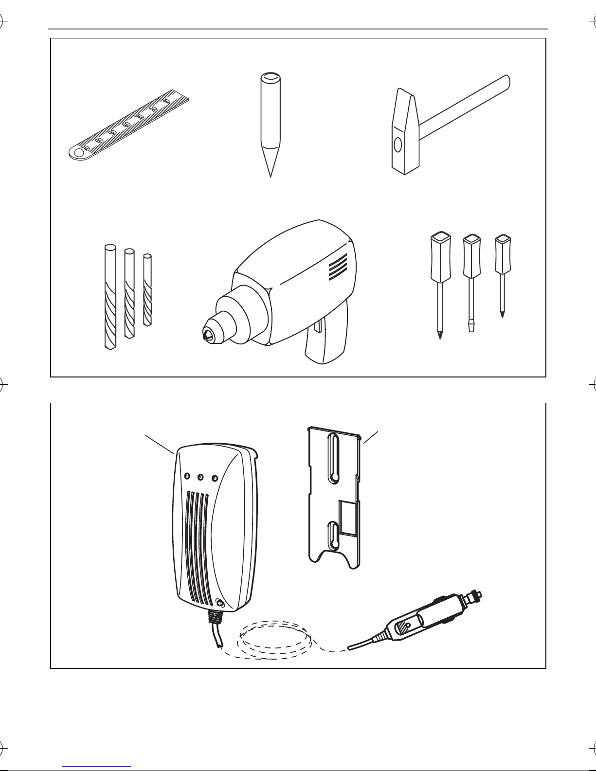
3Scope of delivery
No. in
fig. 2,
page 3
Quan-
tity
Description Ref. no.
1 1 Gas detector 9600000368
2 1 Installation panel
–1Fastening material
12
Page 13

MSG150 Accessories/expansions
EN
4 Accessories/expansions
Description Ref. no.
External siren 9101600008
Additional switch RV-AMP-SW
5Intended use
MagicSafe MSG150 (ref. no. 9600000368) is a gas detector which detects noxious gases before
they can take effect. MSG150 has been designed for use in vehicles to detect noxious gases which
have an ether, chloroform, butane, ethane or trichloroethane basis.
NOTE
I
With a voltage range of 10 to 32 Vg, the gas detector is suitable for use in both cars
and trucks.
6 Technical description
The MSG150 gas detector can be used as a warning device in many areas to detect gases with a
narcotic effect before they can take effect.
The gas detector contains a sensor and an acoustic signal generator and is connected to a
12/24 Vg voltage supply, e.g. the cigarette lighter in a vehicle.
In addition to this, the gas detector contains an internal relay. An external siren of signal lamp can
be connected to this.
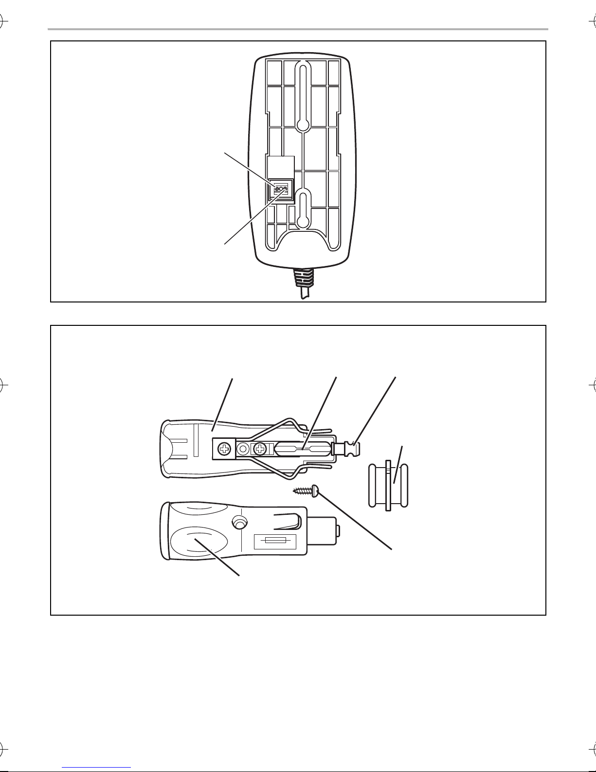
The connection terminal for the relay connection can be found on the back of the gas detector
(fig. 3, page 4).
No. in
fig. 3,
page 4
1 Relay contact 1
2 Relay contact 2
Description
You can operate the gas detector in three ways:
• As single device
• In combination with the external siren (ref. no. 9101600008)
• In combination with the MagicSafe alarm system MS660 or DVS90
13
Page 14

Mounting the MagicSafe MSG150 MSG150
EN
7 Mounting the MagicSafe MSG150
7.1 Tools required
For mounting you will require the following tools:
• Measuring ruler (fig. 1 1, page 3)
• Centre punch (fig. 1 2, page 3)
• Hammer (fig. 1 3, page 3)
• Drill bit set (fig. 1 4, page 3)
• Electric drill (fig. 1 5, page 3)
• Screwdriver (fig. 1 6, page 3)
7.2 Mounting the gas d etector
Note the following when selecting a place to fit the gas detector:
• Note the length of the cable.
• The gas detector should be mounted in the vicinity of the sleeping area at the height of the
mattress.
➤ Select a suitable installation location.
NOTICE!
A
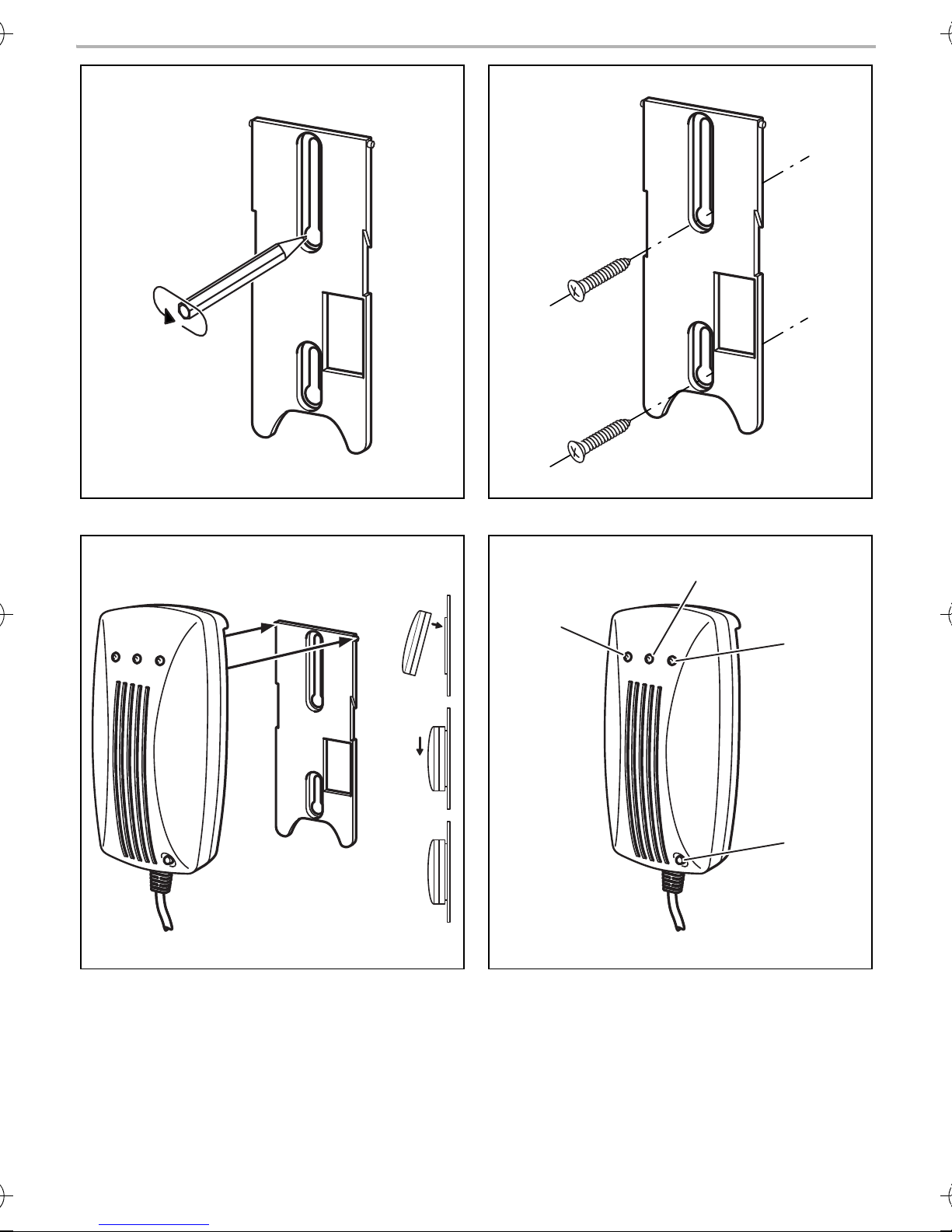
➤ Hold the mounting panel on the chosen location and mark the two drill holes (fig. 5, page 5).
➤ Screw the mounting panel tight with the two self-tapping screws (fig. 6, page 5).
➤ Insert the gas detector on the mounting panel (fig. 7, page 5).
➤ Insert the plug of the gas detector in the socket of your 12/24 Vg voltage supply.
✓ The green LED on the gas detector (fig. 8 1, page 5) flashes for approx. 10 min. The sensor is
then brought to the operating temperature.
When the green LED glows constantly, the gas detector is ready for operation.
Before making any drill holes, ensure that no electrical cables or other parts can be
damaged by drilling.
8 Connecting the gas detector
8.1 As a single device
If you use the gas detector as a single device, you can either
• Switch it on with the 12/24 Vg plug
• Switch it on with the RV-AMP-SW additional switch (accessory), if there is no 12/24 Vg socket
in the sleeping area.
14
Page 15

MSG150 Connecting the gas detector
EN
Connecting the gas detector using the 12/24 Vg plug
➤ Insert the 12/24 Vg plug into a socket with a constant 12/24 Vg supply.
This socket should be connected with the vehicle battery.
✓ An acoustic signal sounds and the green LED (fig. 8 1, page 5) flashes for approx. 10 minutes.
During this time the gas detector conducts a system test and the sensor is brought to operating
temperature.
Connecting the gas detector so that it is hardwired
If you wish to give the gas detector a permanently wired connection and switch it on with the
RV-AMP-SW additional switch, please use the circuit diagram fig. 9, page 6.
➤ Disconnect the 12/24 Vg plug from the cable.
➤ Remove around 10 cm of the outer insulation on the end of the cable.
➤ Connect the black, yellow and orange cable to the bodywork earth (terminal 31).
➤ Connect the red cable to the output of the RV-AMP-SW additional switch.
➤ Connect the input of the switch with a 1 A fuse to the positive battery pole.
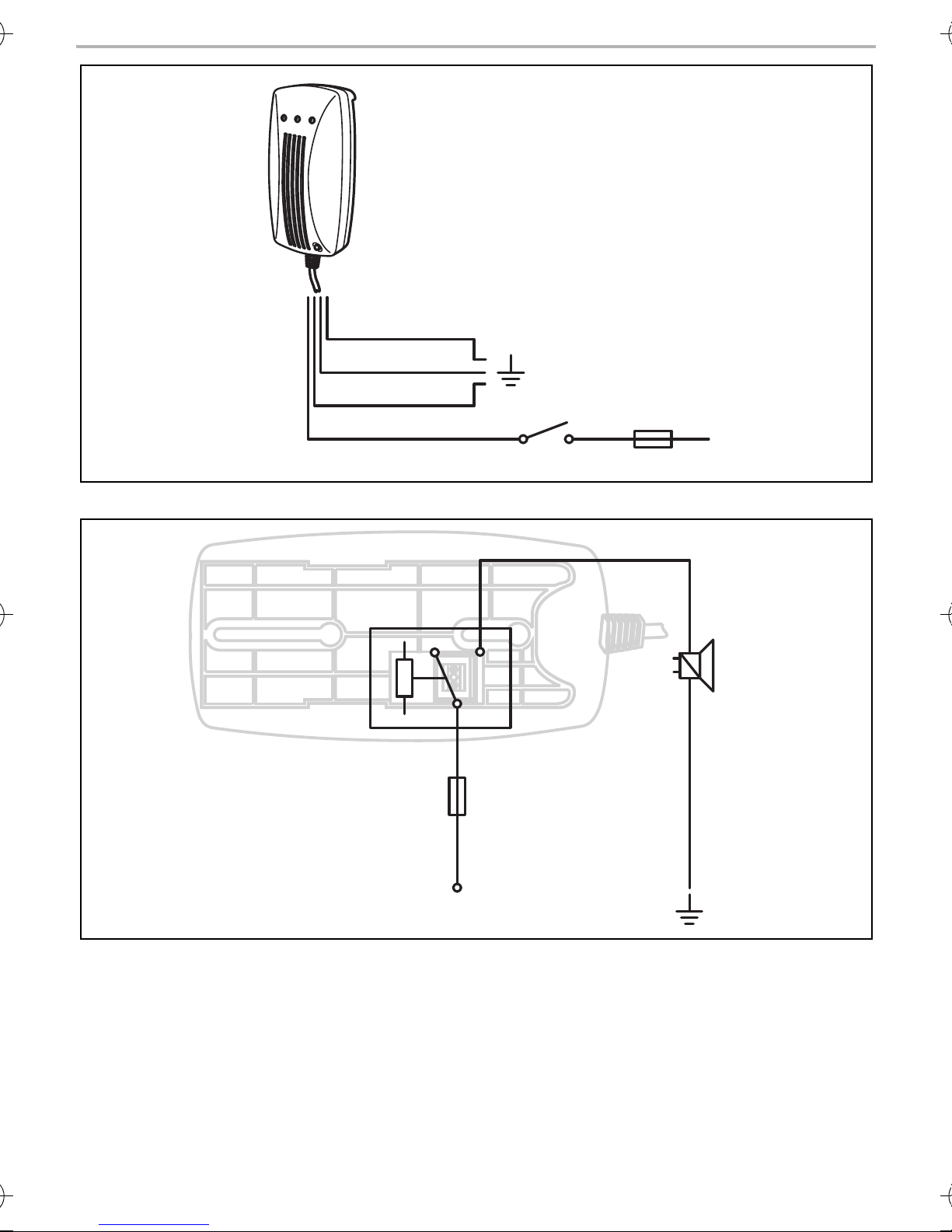
8.2 In combination with the external siren (ref. no. 9101600008)
If you wish to connect the gas detector with the external siren, please use the circuit diagram
fig. 0, page 6.
Mounting the external siren
The external siren can be mounted in the engine compartment.
When mounting it, ensure that the installation location is
• Not in an area exposed to splashing water
• Not near the exhaust system
• Cannot be accessed from underneath the vehicle, to ensure that it cannot be sabotaged.
➤ Mount the external siren with the acoustic horn facing downwards.
Connecting the alarm siren
NOTE
I
If your vehicle does not have a 12 Vg continuous positive cable in the mounting area,
you can also connect the input to the vehicle battery using a 1 A fuse.
➤ Connect the black cable of the siren to the bodywork earth (terminal 31).
➤ Connect the red cable of the siren to the relay contact 2 (fig. 3 2, page 4).
➤ Connect the relay contact 1 (fig. 3 1, page 4) to the 12 Vg continuous positive.
The cable must be fused with at least a 1 A fuse.
15
Page 16

Connecting the gas detector MSG150
EN
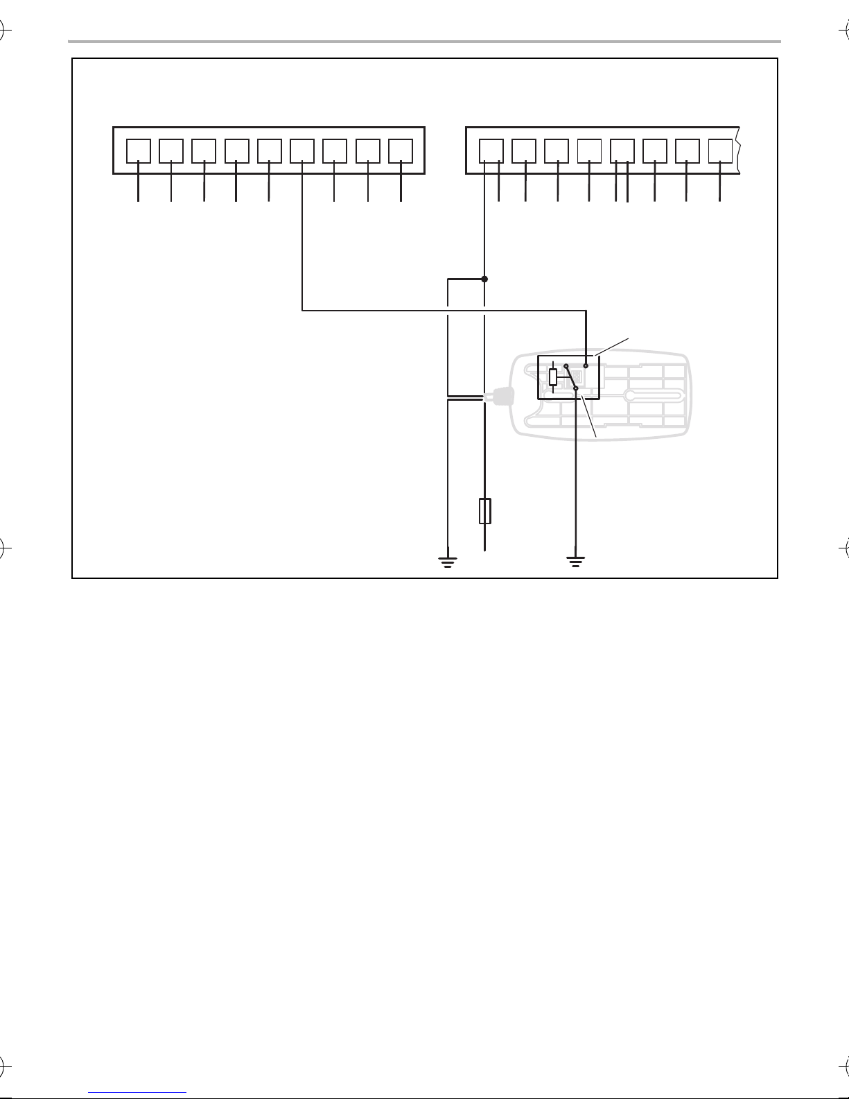
8.3 In combination with an MS660 or DVS90 alarm system
If you wish to use the gas detector in combination with
• the MS660 alarm system, please use the circuit diagram fig. a, page 7
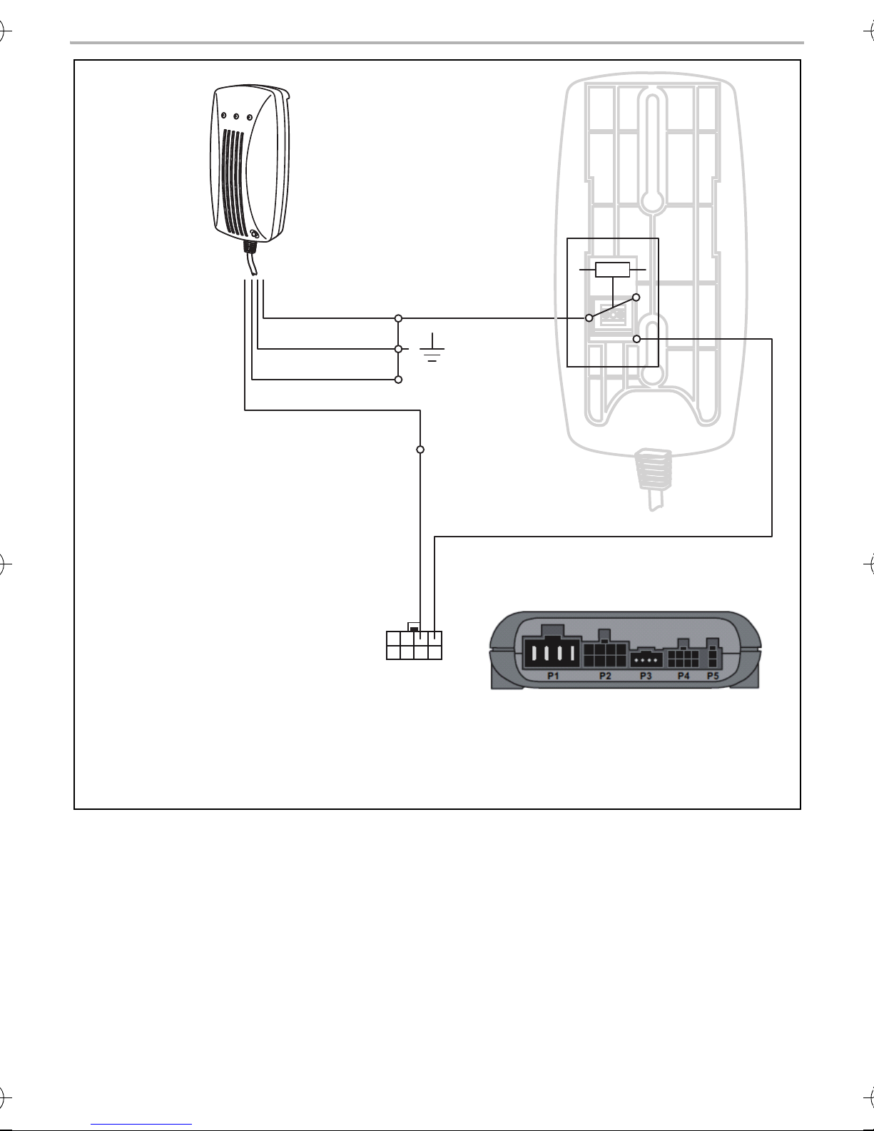
• the DVS90 alarm system, please use the circuit diagram fig. b, page 8
NOTICE!
A
Gas detector with MS660
➤ Disconnect the 12 Vg plug from the cable.
➤ Remove around 10 cm of the outer insulation on the end of the cable.
➤ Connect the black cable to the bodywork earth (terminal 31).
➤ Connect the yellow and orange cable (fig. a, page 7) with the white cable of the alarm
system (pin 15, 15-pin plug).
If you are combining the MagicSafe MSG150 with the DVS90 alarm system, you need
to configure the alarm system as follows:
• Set output 2.6 to “Status-Armed” and input 2.5 to “Trigger”.
➤ Connect the red cable with 12 Vg continuous positive.
The cable must be fused with at least a 1 A fuse.
➤ If the gas detector is to be switched as the main alarm on the MS660 external alarm system,
connect
– relay contact 1 (fig. a, page 7) to the bodywork earth (terminal 31) and
– relay contact 2 (fig. a, page 7) to the grey/white cable (pin 4, 9-pin plug) of the alarm
system.
Gas detector with DVS90
➤ Disconnect the 12/24 Vg plug from the cable.
➤ Remove around 10 cm of the outer insulation on the end of the cable.
➤ Connect the black, yellow and orange cable to the bodywork earth (terminal 31).
➤ Connect the red cable with the green/red cable (P2, pin 6 (fig. b, page 8).
The cable must be fused with at least a 1 A fuse.
➤ If the gas detector is to be switched as the main alarm on the DVS90 external alarm system,
connect
– relay contact 1 (fig. b, page 8) to the bodywork earth (terminal 31) and
– relay contact 2 (fig. b, page 8) to the black/grey cable (P2, pin 5) of the alarm system.
16
Page 17
MSG150 Operating the MagicSafe MSG150
EN
9 Operating the MagicSafe MSG150
To avoid false alarms caused by cooking, using deodorants, heavy smoking and alcohol consumption, the vehicle should be ventilated thoroughly before retiring to bed and then the gas detector
should be switched on.
No. in
fig. 8,
page 5
1 Green LED
2 Orange LED:
description
The green LED flashes for approx. 10 minutes after the gas detector has been
connected to a voltage supply or switched on with the RV-AMP-SW auxiliary
switch. While the LED is flashing, the sensor is brought to the operating
temperature.
When the green LED glows constantly, the gas detector is ready for operation.
The orange LED glows if a fault occurs.
3 Red LED (alarm)
The red LED flashes if an alarm has been triggered.
In addition to this, a siren sounds an alarm signal.
(See also chapter “Alarm” on page 18.)
4 Pushbutton
This pushbutton is a test button and also mutes the system.
Test pushbutton
➤ Press this pushbutton once a month or after extended periods of disuse to
check the system is functioning.
✓ The orange and red LEDs flash and a siren sounds.
Mute switch
➤ Press this pushbutton if you wish to switch off the sound during an alarm.
✓ The red LED continues flashing and a brief signal sounds every 45 seconds.
Then the system is armed again.
Switching on the MSG150 as a single device or in combination with the external siren
(ref. no. 9101600008)
➤ Insert the 12/24 Vg plug in a socket or switch on the gas detector with the RV-AMP-SW
auxiliary switch.
✓ An acoustic signal sounds and the green LED (fig. 8 1, page 5) flashes for approx. 10 minutes.
During this time the gas detector conducts a system test and the sensor is brought to operating
temperature.
If an alarm occurs, an acoustic signal sounds over the internal siren and the red LED (fig. 8 3,
page 5) glows. If the external siren is connected, an additional acoustic signal sounds over the
external siren.
➤ To interrupt the internal alarm, press the pushbutton (fig. 8 4, page 5).
17
Page 18

Alarm MSG150
EN
Switching on the MSG150 in combination with the MS660 or DVS90
➤ Switch the MS660 or DVS90 alarm system on as usual:
On the remote control of the respective device, press
– the lower button (MS660)
– the NO button of the vehicle or additional hand transmitter (DVS90).
✓ An acoustic signal sounds and the green LED (fig. 8 1, page 5) flashes for approx. 10 minutes.
During this time the gas detector conducts a system test and the sensor is brought to operating
temperature.
If an alarm occurs, an acoustic signal sounds over the internal siren and the red LED (fig. 8 3,
page 5) glows. The internal relay sends an earth signal to the alarm input of the external alarm
system. The external alarm system immediately triggers an external alarm using the vehicle
indicators and the vehicle horn or siren.
➤ To interrupt the internal alarm, press the pushbutton (fig. 8 4, page 5).
➤ To deactivate the external alarm, press the following on the remote control of the respective
device:
– The top button (MS660)
– The NC button of the vehicle or additional hand transmitter (DVS90).
10 Alarm
If an alarm is signalled, proceed as follows:
➤ Determine the cause of the alarm immediately.
➤ Instruct children and anybody still asleep to leave the vehicle or boat.
➤ Open all doors and windows as quickly as possible.
➤ Avoid striking matches or any naked flames and turn off any sources of combustion
immediately.
➤ Turn off all gas-powered devices.
➤ Avoid causing sparks (do not use any electrical switches).
➤ Rectify the cause or leave the vehicle or the boat.
False alarm
For your safety, the gas detector is set to be very sensitive. For this reason the sensor also reacts to
other gaseous media. Using aerosols (e.g. propellants in spray cans) or thick tobacco smoke,
heavy alcohol fumes or steam arising from cooking can trigger an alarm even though no gas or
anaesthetic gas is present.
18
Page 19

MSG150 Troubleshooting
EN
11 Troubleshooting
If the device is not ready for operation (the green LED does not glow), proceed as follows:
➤ Make sure the power supply is 12 or 24 Vg.
If the voltage is less than this, or the voltage supply has been interrupted, the gas detector
does not function.
➤ Check the fuse in the plug, if the gas detector is connected using a 12 Vg plug.
Checking the fuse in the 12/24 Vg plug
In the tip of the plug, there is a fuse to protect the gas detector.
If the thin metal connection in the middle between the two metal caps is broken, the fuse is
defective and must be replaced. Replacement fuses are available from customer service.
NOTICE!
A
Make sure that you only use the same fuse type (1 A / 250 V) in the plug. Damage to
the device resulting from using inappropriate fuse types is excluded from guarantee
claims under the terms of the warranty.
To replace the fuse, proceed as follows:
➤ Pull the adapter sleeve (fig. 4 4, page 4) off of the plug.
➤ Unscrew the screw (fig. 4 5, page 4) out of the upper half of the housing (fig. 4 1, page 4).
➤ Carefully lift the upper half of the housing off the lower half (fig. 4 6, page 4).
➤ Take out the contact pin (fig. 4 3, page 4).
➤ Replace the defective fuse (fig. 4 2, page 4) with a new fuse that has the same rating.
➤ Re-assemble the plug in the reverse order.
12 Maintaining and cleaning the gas detector
NOTICE!
A
➤ Occasionally clean the product with a damp cloth.
Do not use sharp or hard objects or cleaning agents for cleaning as these may damage
the product.
19
Page 20
Warranty MSG150
EN
13 Warranty
The statutory warranty period applies. If the product is defective, please contact the
manufacturer's branch in your country (see the back of the instruction manual for the addresses) or
your retailer.
For repair and guarantee processing, please include the following documents when you send in
the device:
• A copy of the receipt with purchasing date
• A reason for the claim or description of the fault
14 Disposal
➤ Place the packaging material in the appropriate recycling waste bins wherever possible.
If you wish to finally dispose of the product, ask your local recycling centre or specialist
dealer for details about how to do this in accordance with the applicable disposal
M
regulations.
15 Technical data
MagicSafe MSG150
Ref. no.: 9600000368
Dimensions (W x H x D): 80 x 156 x 51 mm
Input voltage range: 10 Vg to 32 Vg
Power consumption: 1.3 W
Operating temperature: 0 °C to +40 °C
Signal volume: Approx. 85 dB at a distance of 3 m
Protection class: IP 20
Replacement fuse: 1 A / 250 V
Approvals
20
Page 21

MSG150
DE
Bitte lesen Sie diese Anleitung vor Einbau und Inbetriebnahme sorgfältig durch und
bewahren Sie sie auf. Geben Sie sie im Falle einer Weitergabe des Produktes an den
Nutzer weiter.
Inhaltsverzeichnis
1 Erklärung der Symbole . . . . . . . . . . . . . . . . . . . . . . . . . . . . . . . . . . . . . . . . . . . . . . . . . . . . . .22
2 Sicherheits- und Einbauhinweise. . . . . . . . . . . . . . . . . . . . . . . . . . . . . . . . . . . . . . . . . . . . . .22
3 Lieferumfang . . . . . . . . . . . . . . . . . . . . . . . . . . . . . . . . . . . . . . . . . . . . . . . . . . . . . . . . . . . . . .23
4 Zubehör/Erweiterungen . . . . . . . . . . . . . . . . . . . . . . . . . . . . . . . . . . . . . . . . . . . . . . . . . . . .23
5 Bestimmungsgemäßer Gebrauch . . . . . . . . . . . . . . . . . . . . . . . . . . . . . . . . . . . . . . . . . . . . .24
6 Technische Beschreibung . . . . . . . . . . . . . . . . . . . . . . . . . . . . . . . . . . . . . . . . . . . . . . . . . . .24
7 MagicSafe MSG150 montieren. . . . . . . . . . . . . . . . . . . . . . . . . . . . . . . . . . . . . . . . . . . . . . .25
8 Gasmelder anschließen . . . . . . . . . . . . . . . . . . . . . . . . . . . . . . . . . . . . . . . . . . . . . . . . . . . . .26
9 MagicSafe MSG150 bedienen . . . . . . . . . . . . . . . . . . . . . . . . . . . . . . . . . . . . . . . . . . . . . . .28
10 Alarm . . . . . . . . . . . . . . . . . . . . . . . . . . . . . . . . . . . . . . . . . . . . . . . . . . . . . . . . . . . . . . . . . . . .30
11 Fehler suchen . . . . . . . . . . . . . . . . . . . . . . . . . . . . . . . . . . . . . . . . . . . . . . . . . . . . . . . . . . . . .30
12 Gasmelder pflegen und reinigen. . . . . . . . . . . . . . . . . . . . . . . . . . . . . . . . . . . . . . . . . . . . . . 31
13 Gewährleistung . . . . . . . . . . . . . . . . . . . . . . . . . . . . . . . . . . . . . . . . . . . . . . . . . . . . . . . . . . . 31
14 Entsorgung . . . . . . . . . . . . . . . . . . . . . . . . . . . . . . . . . . . . . . . . . . . . . . . . . . . . . . . . . . . . . . .32
15 Technische Daten . . . . . . . . . . . . . . . . . . . . . . . . . . . . . . . . . . . . . . . . . . . . . . . . . . . . . . . . . .32
21
Page 22

Erklärung der Symbole MSG150
DE
1 Erklärung der Symbole
WARNUNG!
!
!
A
I
Sicherheitshinweis: Nichtbeachtung kann zu Tod oder schwerer Verletzung führen.
VORSICHT!
Sicherheitshinweis: Nichtbeachtung kann zu Verletzungen führen.
ACHTUNG!
Nichtbeachtung kann zu Materialschäden führen und die Funktion des Produktes
beeinträchtigen.
HINWEIS
Ergänzende Informationen zur Bedienung des Produktes.
2 Sicherheits- und Einbauhinweise
Der Hersteller übernimmt in folgenden Fällen keine Haftung für Schäden:
• Beschädigungen am Produkt durch mechanische Einflüsse und Überspannungen
• Veränderungen am Produkt ohne ausdrückliche Genehmigung vom Hersteller
• Verwendung für andere als die in der Anleitung beschriebenen Zwecke
2.1 Grundlegende Sicherheit
WARNUNG!
• Benutzen Sie das Gerät nur zu seinem bestimmungsgemäßen Gebrauch.
!
• Trennen Sie das Gerät vom Netz
–vor jeder Reinigung und Pflege
– nach jedem Gebrauch
– vor einem Sicherungswechsel
• Wenn das Gerät oder das Anschlusskabel sichtbare Beschädigungen aufweisen,
dürfen Sie das Gerät nicht in Betrieb nehmen.
• Wenn das Anschlusskabel dieses Gerätes beschädigt wird, muss es durch den
Hersteller, seinen Kundendienst oder eine ähnlich qualifizierte Person ersetzt
werden, um Gefährdungen zu vermeiden.
• Reparaturen an diesem Gerät dürfen nur von Fachkräften durchgeführt werden.
Durch unsachgemäße Reparaturen können erhebliche Gefahren entstehen.
22
Page 23

MSG150 Lieferumfang
DE
• Dieses Gerät kann von Kindern ab 8 Jahren und darüber sowie von Personen mit
verringerten physischen, sensorischen oder mentalen Fähigkeiten oder Mangel an
Erfahrung und Wissen benutzt werden, wenn sie beaufsichtigt oder bezüglich des
sicheren Gebrauchs des Gerätes unterwiesen wurden und die daraus resultierenden
Gefahren verstehen.
• Elektrogeräte sind kein Kinderspielzeug!
Verwahren und benutzen Sie das Gerät außerhalb der Reichweite von Kindern.
• Kinder sollten beaufsichtigt werden, um sicherzustellen, dass sie nicht mit dem Gerät
spielen.
ACHTUNG!
A
• Vergleichen Sie vor der Inbetriebnahme die Spannungsangabe auf dem Typenschild
mit der vorhandenen Energieversorgung.
• Ziehen Sie den Stecker nie am Anschlusskabel aus der Steckdose.
• Lagern Sie das Gerät an einem trockenen und kühlen Ort.
2.2 Sicherheit beim Betrieb des Gerätes
• Betreiben Sie das Gerät in Fahrzeugen ausschließlich bei abgestelltem Motor.
• Betreiben Sie das Gerät nicht im Freien.
• Testen Sie einmal im Monat und nach längeren Ruhezeiten die Funktion des Gerätes durch
Drücken des Tasters (Abb. 8 4, Seite 5).
3Lieferumfang
Nr. in
Abb. 2,
Seite 3
Menge Bezeichnung Artikel-Nr.
1 1 Gasmelder 9600000368
21Montageplatte
–1Befestigungsmaterial
4 Zubehör/Erweiterungen
Bezeichnung Artikel-Nr.
Außensirene 9101600008
Zusatzschalter RV-AMP-SW
23
Page 24

Bestimmungsgemäßer Gebrauch MSG150
DE
5 Bestimmungsgemäßer Gebrauch
MagicSafe MSG150 (Art.-Nr. 9600000368) ist ein Gasmelder, der narkotisch wirkende Gase
erkennt, bevor sie ihre Wirkung erreichen. MSG150 ist konzipiert für die Verwendung in Fahrzeugen, um narkotisch wirkende Gase zu erkennen, die auf Äther, Chloroform, Butan, Ethan und
Triclorethene basieren.
HINWEIS
I
Durch einen Spannungsbereich von 10 bis 32 Vg ist der Gasmelder sowohl für den
Einsatz in Pkw als auch in Lkw geeignet.
6 Technische Beschreibung
Der Gasmelder MSG150 kann vielseitig als Warngerät eingesetzt werden, um narkotisch
wirkende Gase zu erkennen, bevor sie ihre Wirkung erreichen.
Der Gasmelder enthält einen Sensor sowie einen akustischen Signalgeber und wird an eine
12/24-Vg-Spannungsquelle angeschlossen, z. B. an den Zigarettenanzünder in Fahrzeugen.
Außerdem enthält der Gasmelder ein internes Relais, an das z. B. eine Außensirene oder eine
Signallampe angeschlossen werden kann.
Die Anschlussklemme für den Relaisanschluss befindet sich auf der Rückseite des Gasmelders
(Abb. 3, Seite 4).
Nr. in
Abb. 3,
Seite 4
1Relaiskontakt1
2Relaiskontakt2
Sie können Gasmelder auf drei Arten verwenden:
• als Einzelgerät
• in Kombination mit der Außensirene (Art.-Nr. 9101600008)
• in Kombination mit der MagicSafe Alarmanlage MS660 oder DVS90
Bezeichnung
24
Page 25

MSG150 MagicSafe MSG150 montieren
DE
7 MagicSafe MSG150 montieren
7.1 Benötigtes Werkzeug
Für die Montage benötigen Sie folgende Werkzeuge:
• Maßstab (Abb. 1 1, Seite 3)
• Körner (Abb. 1 2, Seite 3)
• Hammer (Abb. 1 3, Seite 3)
• Satz Bohrer (Abb. 1 4, Seite 3)
• Bohrmaschine (Abb. 1 5, Seite 3)
• Schraubendreher (Abb. 1 6, Seite 3)
7.2 Gasmelder montieren
Berücksichtigen Sie folgende Hinweise bei der Auswahl des Montageortes für den Gasmelder:
• Beachten Sie die Länge des Kabels.
• Der Gasmelder sollte in der Nähe des Schlafbereiches montiert werden und in der Höhe der
Matratze.
➤ Wählen Sie einen geeigneten Montageort.
ACHTUNG!
A
➤ Halten Sie die Montageplatte an den gewählten Montageort und markieren Sie die beiden
Bohrpunkte (Abb. 5, Seite 5).
➤ Schrauben Sie die Montageplatte mit den beiden Blechschrauben fest (Abb. 6, Seite 5).
➤ Stecken Sie den Gasmelder auf die Montageplatte (Abb. 7, Seite 5).
➤ Stecken Sie den Stecker des Gasmelders in die Buchse Ihrer 12/24-Vg-Spannungs-
versorgung.
✓ Die grüne LED am Gasmelder (Abb. 8 1, Seite 5) blinkt etwa 10 min lang. Der Sensor wird auf
Betriebstemperatur gebracht.
Wenn die grüne LED dauernd leuchtet, ist der Gasmelder betriebsbereit.
Bevor Sie Bohrungen vornehmen, stellen Sie sicher, dass keine elektrischen Kabel
oder andere Teile durch Bohren beschädigt werden.
25
Page 26

Gasmelder anschließen MSG150
DE
8 Gasmelder anschließen
8.1 Als Einzelgerät
Wenn Sie den Gasmelder als Einzelgerät benutzen, können Sie ihn entweder
• über den 12/24-Vg-Stecker einschalten
• über den als Zubehör erhältlichen Zusatzschalter RV-AMP-SW (Zubehör) einschalten, wenn
keine 12/24-Vg-Steckdose im Schlafbereich vorhanden ist.
Gasmelder über den 12/24-Vg-Stecker anschließen
➤ Stecken Sie den 12/24-Vg-Stecker in eine Steckdose, die 12/24-Vg-Dauerplus führt.
Diese Steckdose sollte mit der Fahrzeugbatterie verbunden sein.
✓ Ein akustisches Signal ertönt, und die grüne LED (Abb. 8 1, Seite 5) blinkt für etwa zehn
Minuten.
Während dieser Zeit führt der Gasmelder einen Systemtest durch, und der Sensor wird auf
Betriebstemperatur gebracht.
Gasmelder fest verdrahtet anschließen
Wenn Sie den Gasmelder fest verdrahtet anschließen und über den Zusatzschalter RV-AMP-SW
einschalten möchten, verwenden Sie den Schaltplan Abb. 9, Seite 6.
➤ Trennen Sie den 12/24-Vg-Stecker vom Kabel.
➤ Entfernen Sie etwa 10 cm der Außenisolierung am Ende des Kabels.
➤ Verbinden Sie jeweils das schwarze, gelbe und orangene Kabel mit der Karosseriemasse
(Klemme 31).
➤ Verbinden Sie die rote Leitung mit dem Ausgang des Zusatzschalters RV-AMP-SW.
➤ Verbinden Sie den Eingang des Schalters über eine 1-A-Sicherung mit dem Pluspol der
Batterie.
8.2 In Kombination mit der Außensirene (Art.-Nr. 9101600008)
Wenn Sie den Gasmelder in Kombination mit der Außensirene anschließen möchten, verwenden
Sie den Schaltplan Abb. 0, Seite 6.
Außensirene montieren
Die Außensirene kann im Motorraum montieren werden.
Achten Sie bei der Montage darauf, dass der Montageort
• nicht im Spritzwasserbereich liegt
• nicht in der Nähe der Auspuffanlage liegt
• nicht von der Unterseite zugänglich ist, um Sabotage von außen zu verhindern
➤ Montieren Sie die Außensirene mit dem Schalltrichter nach unten.
26
Page 27

MSG150 Gasmelder anschließen
DE
Alarmsirene anschließen
HINWEIS
I
➤ Verbinden das schwarze Kabel der Sirene mit der Karosseriemasse (Klemme 31).
➤ Verbinden Sie das rote Kabel der Sirene mit dem Relaiskontakt 2 (Abb. 3 2, Seite 4).
➤ Verbinden Sie den Relaiskontakt 1 (Abb. 3 1, Seite 4) mit 12-Vg-Dauerplus.
Die Leitung muss mit einer 1-A-Sicherung abgesichert sein.
Falls Ihr Fahrzeug im Montagebereich keine 12-Vg-Dauerplusleitung hat, können Sie
den Eingang auch über eine 1-A-Sicherung an die Fahrzeugbatterie anschließen.
8.3 In Kombination mit einer Alarmanlage MS660 oder DVS90
Wenn Sie den Gasmelder in Kombination mit
• der Alarmanlage MS660 anschließen möchten, verwenden Sie den Schaltplan Abb. a,
Seite 7
• der Alarmanlage DVS90 anschließen möchten, verwenden Sie den Schaltplan Abb. b,
Seite 8
ACHTUNG!
A
Gasmelder mit MS660
➤ Trennen Sie den 12-Vg-Stecker vom Kabel.
➤ Entfernen Sie etwa 10 cm der Außenisolierung am Ende des Kabels.
➤ Verbinden Sie die schwarze Leitung mit der Karosseriemasse (Klemme 31).
➤ Verbinden Sie die gelbe und die orangefarbene Leitung (Abb. a, Seite 7) mit der weißen
Leitung der Alarmanlage (Pin 15, 15-poliger Stecker).
➤ Verbinden Sie die rote Leitung mit 12-Vg-Dauerplus.
Die Leitung muss mit einer 1-A-Sicherung abgesichert sein.
➤ Wenn der Gasmelder auch als Hauptalarm auf die externe Alarmanlage MS660 geschaltet
werden soll, schließen Sie
– den Relaiskontakt 1 (Abb. a, Seite 7) an die Karosseriemasse (Klemme 31) an und
– den Relaiskontakt 2 (Abb. a, Seite 7) an die grau/weiße Leitung (Pin 4, 9-poliger Stecker)
Wenn Sie MagicSafe MSG150 mit der Alarmanlage DVS90 kombinieren, müssen Sie
die Software der Alarmanlage wie folgt konfigurieren:
• Setzen Sie den Ausgang 2.6 auf „Status-Scharf“ und den Eingang 2.5 auf
„Auslöser“.
der Alarmanlage an.
27
Page 28
MagicSafe MSG150 bedienen MSG150
DE
Gasmelder mit DVS90
➤ Trennen Sie den 12/24-Vg-Stecker vom Kabel.
➤ Entfernen Sie etwa 10 cm der Außenisolierung am Ende des Kabels.
➤ Verbinden Sie die schwarze, gelbe und orangefarbene Leitung mit der Karosseriemasse
(Klemme 31).
➤ Verbinden Sie die rote Leitung mit der grün/roten Leitung (P2, Pin 6) (Abb. b, Seite 8).
Die Leitung muss mit einer 1-A-Sicherung abgesichert sein.
➤ Wenn der Gasmelder auch als Hauptalarm auf die externe Alarmanlage DVS90 geschaltet
werden soll, schließen Sie
– den Relaiskontakt 1 (Abb. b, Seite 8) an die Karosseriemasse (Klemme 31) an und
– den Relaiskontakt 2 (Abb. b, Seite 8) an die schwarz/graue Leitung (P2, Pin 5) der
Alarmanlage an.
9 MagicSafe MSG150 bedienen
Um Fehlalarme durch Kochen, Verwendung von Deos, starken Tabak- oder Alkoholgenuss zu
vermeiden, sollte das Fahrzeug vor dem Schlafengehen erst gut durchlüftet werden und der
Gasmelder danach eingeschaltet werden.
Nr. in
Abb. 8,
Seite 5
1 Grüne LED
2 Orangene LED
3 Rote LED (Alarm)
Bezeichnung
Die grüne LED blinkt etwa 10 min lang, nachdem der Gasmelder an
Spannung angeschlossen oder über den Zusatzschalter RV-AMP-SW
eingeschaltet wurde. Während die LED blinkt, wird der Sensor auf
Betriebstemperatur gebracht.
Wenn die grüne LED dauernd leuchtet, ist der Gasmelder betriebsbereit.
Die orangene LED leuchtet, wenn eine Störung auftritt.
Die rote LED blinkt, wenn ein Alarm ausgelöst wird.
Zusätzlich ertönt ein Sirenenton als akustisches Alarmsignal.
(Siehe auch Kapitel „Alarm“ auf Seite 30.)
28
Page 29

MSG150 MagicSafe MSG150 bedienen
DE
Nr. in
Abb. 8,
Bezeichnung
Seite 5
4 Taster
Dieser Taster dient als Testtaster und als Stummschalter.
Testtaster
➤ Drücken Sie diesen Taster einmal im Monat oder nach längeren
Ruhezeiten, um die Funktion zu prüfen.
✓ Die orangene und die rote LED blinken, und ein Sirenenton ertönt.
Stummschalter
➤ Drücken Sie den Taster, wenn Sie den Signalton während eines Alarms
abstellen möchten.
✓ Die rote LED blinkt weiterhin, und nach 45 s ertönt ein kurzer Signalton.
Anschließend schaltet sich die Anlage wieder scharf.
MSG150 als Einzelgerät oder in Kombination mit der Außensirene (Art.-Nr.
9101600008) einschalten
➤ Stecken Sie den 12/24-Vg-Stecker in eine Steckdose oder schalten Sie den Gasmelder über
den Zusatzschalter RV-AMP-SW ein.
✓ Ein akustisches Signal ertönt, und die grüne LED (Abb. 8 1, Seite 5) blinkt für etwa zehn
Minuten.
Während dieser Zeit führt der Gasmelder einen Systemtest durch, und der Sensor wird auf
Betriebstemperatur gebracht.
Wenn ein Alarm auftritt, ertönt ein akustisches Signal über die interne Sirene und die rote LED
(Abb. 8 3, Seite 5) leuchtet auf. Falls die Außensirene angeschlossen ist, ertönt zusätzlich ein
akustischer Alarm über die Außensirene.
➤ Um den internen Alarm zu unterbrechen, drücken Sie den Taster (Abb. 8 4, Seite 5).
MSG150 in Kombination mit MS660 oder DVS90 einschalten
➤ Schalten Sie die Alarmanlage MS660 oder DVS90 wie gewohnt ein:
Betätigen Sie an deren Fernbedienung
– die untere Taste (MS660)
– die Schließer-Taste vom Fahrzeug- bzw. Zusatzhandsender (DVS90).
✓ Ein akustisches Signal ertönt, und die grüne LED (Abb. 8 1, Seite 5) blinkt für etwa zehn
Minuten.
Während dieser Zeit führt der Gasmelder einen Systemtest durch, und der Sensor wird auf
Betriebstemperatur gebracht.
Wenn ein Alarm auftritt, ertönt ein akustisches Signal über die interne Sirene und die rote LED
(Abb. 8 3, Seite 5) leuchtet auf. Das interne Relais schaltet ein Massesignal auf den Alarmeingang der externen Alarmanlage. Die externe Alarmanlage löst unmittelbar einen Außenalarm über
die Fahrzeugblinker und die Fahrzeughupe oder die Sirene aus.
➤ Um den internen Alarm zu unterbrechen, drücken Sie den Taster (Abb. 8 4, Seite 5).
29
Page 30

Alarm MSG150
DE
➤ Zur Deaktivierung der externen Alarmanlage betätigen Sie an deren Fernbedienung
– die obere Taste (MS660)
– die Öffner-Taste vom Fahrzeug- bzw. Zusatzhandsender (DVS90).
10 Alarm
Gehen Sie wie folgt vor, wenn ein Alarm signalisiert wird:
➤ Stellen Sie sofort die Ursache des Alarms fest.
➤ Veranlassen Sie Kinder und schlafende Personen zum Verlassen des Fahrzeugs oder des
Bootes.
➤ Öffnen Sie unverzüglich alle Fenster und Türen.
➤ Vermeiden Sie offenes Feuer und stellen Sie offene Brennstellen sofort ab.
➤ Stellen Sie alle gasbetriebenen Geräte ab.
➤ Vermeiden Sie Funkenbildung (betätigen Sie keine elektrischen Schalter).
➤ Beheben Sie die Ursache oder verlassen Sie das Fahrzeug oder das Boot.
Fehlalarm
Der Gasmelder ist für Ihre Sicherheit sehr empfindlich eingestellt. Deshalb spricht der Sensor auch
auf andere gasförmige Medien an. Der Gebrauch von Aerosolen (z. B. Treibgas in Sprays), aber
auch starker Tabakqualm, starke Alkoholausdünstungen oder Dampf beim Kochen können einen
Alarm auslösen, obwohl kein Gas oder Betäubungsgas vorhanden ist.
11 Fehler suchen
Wenn das Gerät nicht betriebsbereit ist (grüne LED leuchtet nicht), gehen Sie wie folgt vor:
➤ Stellen Sie sicher, dass die Versorgungsspannung 12 oder 24 Vg beträgt.
Wenn die Spannung geringer ist oder die Spannungszufuhr unterbrochen wurde, funktioniert
der Gasmelder nicht.
➤ Prüfen Sie die Sicherung im Stecker, falls der Gasmelder über den 12/24-Vg-Stecker
angeschlossen ist.
30
Page 31

MSG150 Gasmelder pflegen und reinigen
DE
Sicherung im 12/24-Vg-Stecker überprüfen
In der Spitze des Steckers befindet sich zum Schutz des Gasmelders eine Schmelzsicherung.
Wenn die dünne Metallverbindung in der Mitte zwischen den beiden Metallkappen unterbrochen
ist, dann ist die Sicherung defekt und muss ersetzt werden. Ersatzsicherungen sind beim Kundendienst erhältlich.
ACHTUNG!
A
Zum Austausch der Sicherung gehen Sie wie folgt vor:
➤ Ziehen Sie die Ausgleichshülse (Abb. 4 4, Seite 4) vom Stecker ab.
➤ Drehen Sie die Schraube (Abb. 4 5, Seite 4) aus der oberen Gehäusehälfte (Abb. 4 1,
Seite 4) heraus.
➤ Heben Sie vorsichtig die obere Gehäusehälfte von der unteren (Abb. 4 6, Seite 4) ab.
Achten Sie darauf, dass Sie ausschließlich den gleichen Sicherungstyp (1 A/250 V)
in den Stecker einsetzen. Geräteschäden, die durch das Einsetzen von falschen
Sicherungswerten entstehen, sind von jeglicher Gewährleistung und Ersatzleistung
ausgeschlossen.
➤ Nehmen Sie den Kontaktstift (Abb. 4 3, Seite 4) heraus.
➤ Tauschen Sie die defekte Sicherung (Abb. 4 2, Seite 4) gegen eine neue Sicherung mit
demselben Wert aus.
➤ Setzen Sie den Stecker in umgekehrter Reihenfolge wieder zusammen.
12 Gasmelder pflegen und reinigen
ACHTUNG!
A
➤ Reinigen Sie das Produkt gelegentlich mit einem feuchten Tuch.
Keine scharfen oder harten Gegenstände oder Reinigungsmittel zur Reinigung verwenden, da dies zu einer Beschädigung des Produktes führen kann.
13 Gewährleistung
Es gilt die gesetzliche Gewährleistungsfrist. Sollte das Produkt defekt sein, wenden Sie sich bitte
an die Niederlassung des Herstellers in Ihrem Land (Adressen siehe Rückseite der Anleitung) oder
an Ihren Fachhändler.
Zur Reparatur- bzw. Gewährleistungsbearbeitung müssen Sie folgende Unterlagen mitschicken:
• eine Kopie der Rechnung mit Kaufdatum,
• einen Reklamationsgrund oder eine Fehlerbeschreibung.
31
Page 32

Entsorgung MSG150
DE
14 Entsorgung
➤ Geben Sie das Verpackungsmaterial möglichst in den entsprechenden Recycling-Müll.
Wenn Sie das Produkt endgültig außer Betrieb nehmen, informieren Sie sich bitte beim
nächsten Recyclingcenter oder bei Ihrem Fachhändler über die zutreffenden
M
Entsorgungsvorschriften.
15 Technische Daten
MagicSafe MSG150
Artikelnummer: 9600000368
Maße (B x H x T): 80 x 156 x 51 mm
Eingangsspannungsbereich: 10 Vg bis 32 Vg
Leistungaufnahme: 1,3 W
Betriebstemperatur: 0 °C bis +40 °C
Signallautstärke: ca. 85 dB in einem Abstand von 3 m
Schutzklasse: IP 20
Ersatzsicherung: 1 A/250 V
Zulassungen
32
Page 33

MSG150
FR
Veuillez lire attentivement cette notice avant le montage et la mise en service. Veuillez
ensuite la conserver. En cas de passer le produit, veuillez le transmettre au nouvel
acquéreur.
Sommaire
1 Symboles. . . . . . . . . . . . . . . . . . . . . . . . . . . . . . . . . . . . . . . . . . . . . . . . . . . . . . . . . . . . . . . . .34
2 Consignes de sécurité et instructions de montage. . . . . . . . . . . . . . . . . . . . . . . . . . . . . . . .34
3 Contenu de la livraison. . . . . . . . . . . . . . . . . . . . . . . . . . . . . . . . . . . . . . . . . . . . . . . . . . . . . .35
4 Accessoires/Extensions . . . . . . . . . . . . . . . . . . . . . . . . . . . . . . . . . . . . . . . . . . . . . . . . . . . . .35
5 Usage conforme . . . . . . . . . . . . . . . . . . . . . . . . . . . . . . . . . . . . . . . . . . . . . . . . . . . . . . . . . . .36
6 Description technique . . . . . . . . . . . . . . . . . . . . . . . . . . . . . . . . . . . . . . . . . . . . . . . . . . . . . .36
7 Montage du MagicSafe MSG150 . . . . . . . . . . . . . . . . . . . . . . . . . . . . . . . . . . . . . . . . . . . . .37
8 Raccordement du détecteur de gaz . . . . . . . . . . . . . . . . . . . . . . . . . . . . . . . . . . . . . . . . . . .38
9 Utilisation du MagicSafe MSG150. . . . . . . . . . . . . . . . . . . . . . . . . . . . . . . . . . . . . . . . . . . . .40
10 Alarme. . . . . . . . . . . . . . . . . . . . . . . . . . . . . . . . . . . . . . . . . . . . . . . . . . . . . . . . . . . . . . . . . . .42
11 Recherche de pannes. . . . . . . . . . . . . . . . . . . . . . . . . . . . . . . . . . . . . . . . . . . . . . . . . . . . . . .42
12 Entretien et nettoyage du détecteur de gaz . . . . . . . . . . . . . . . . . . . . . . . . . . . . . . . . . . . . .43
13 Garantie. . . . . . . . . . . . . . . . . . . . . . . . . . . . . . . . . . . . . . . . . . . . . . . . . . . . . . . . . . . . . . . . . .43
14 Retraitement . . . . . . . . . . . . . . . . . . . . . . . . . . . . . . . . . . . . . . . . . . . . . . . . . . . . . . . . . . . . . .44
15 Caractéristiques techniques. . . . . . . . . . . . . . . . . . . . . . . . . . . . . . . . . . . . . . . . . . . . . . . . . .44
33
Page 34

Symboles MSG150
FR
1Symboles
AVERTISSEMENT !
!
!
A
I
Consigne de sécurité : le non-respect de ces consignes peut entraîner la mort ou de
graves blessures.
ATTENTION !
Consigne de sécurité : le non-respect de ces consignes peut entraîner des bles-
sures.
AVIS !
Le non-respect de ces consignes peut entraîner des dommages matériels et des dysfonctionnements du produit.
REMARQUE
Informations complémentaires sur l'utilisation du produit.
2 Consignes de sécurité et instructions de montage
Le fabricant décline toute responsabilité pour des dommages dans les cas suivants :
• des influences mécaniques et des surtensions ayant endommagé le matériel
• des modifications apportées au produit sans autorisation explicite de la part du fabricant
• une utilisation différente de celle décrite dans la notice
2.1 Consignes générales de sécurité
AVERTISSEMENT !
• Utilisez l'appareil conformément à l'usage pour lequel il a été conçu.
!
• Débranchez l'appareil du secteur
– avant tout nettoyage et entretien
– après chaque utilisation
– avant le changement d'un fusible
• Si l’appareil ou le câble de raccordement présentent des dommages visibles, il est
interdit de mettre l'appareil en service.
• Si le câble de raccordement de l'appareil est endommagé, il doit être remplacé par
le fabricant, son service après-vente ou une personne de qualification similaire, afin
d'éviter tout danger.
• Seul un personnel qualifié est habilité à effectuer des réparations sur l'appareil. Toute
réparation mal effectuée risquerait d'entraîner de graves dangers.
34
Page 35

MSG150 Contenu de la livraison
FR
• Les enfants âgés de 8 ans et plus ainsi que les personnes ayant des déficiences
physiques, sensorielles ou mentales ou un manque d'expérience ou de connaissances peuvent utiliser ce produit à condition d'être sous surveillance ou d'avoir reçu
des instructions concernant l'utilisation de l'appareil en toute sécurité et de comprendre les dangers qui en résultent.
• Les appareils électriques ne sont pas des jouets pour enfants !
Placez et utilisez l'appareil hors de leur portée.
• Les enfants doivent être surveillés pour s'assurer qu'ils ne jouent pas avec l'appareil.
AVIS !
A
• Avant la mise en service, vérifiez que la tension indiquée sur la plaque signalétique
correspond à l'alimentation électrique dont vous disposez.
• Ne tirez jamais sur le câble de raccordement pour sortir la fiche de la prise.
• Stockez l'appareil dans un endroit frais et sec.
2.2 Consignes de sécurité concernant le fonctionnement de l'appareil
• Faites fonctionner l'appareil dans les véhicules uniquement lorsque le moteur est arrêté.
• N'utilisez pas l'appareil en plein air.
• Procédez à un test de fonctionnement une fois par mois et après des périodes prolongées
d'inutilisation sur l'appareil en appuyant sur la touche (fig. 8 4, page 5).
3 Contenu de la livraison
N° dans
fig. 2,
page 3
Quan-
tité
Désignation N° d'article
1 1 Détecteur de gaz 9600000368
2 1 Plaque de montage
– 1 Matériel de fixation
4 Accessoires/Extensions
Désignation N° d'article
Sirène extérieure 9101600008
Interrupteur supplémentaire RV-AMP-SW
35
Page 36

Usage conforme MSG150
FR
5Usage conforme
Le MagicSafe MSG 150 (n° de produit 9600000368) est un détecteur de gaz décelant des gaz aux
propriétés narcotiques avant que ceux-ci n'agissent. Le MSG150 est conçu pour être utilisé dans
des véhicules et pour la détection de gaz aux propriétés narcotiques à base d'éther, de chloroforme, de butane, d'éthane et de trichloréthylène.
REMARQUE
I
Grâce à sa plage de tension comprise entre 10 et 32 Vg, le détecteur de gaz convient
pour les voitures aussi bien que les poids lourds.
6 Description technique
Le détecteur de gaz MSG150 peut être utilisé comme appareil de prévention polyvalent dans le
but de détecter des gaz aux propriétés narcotiques avant que ceux-ci n'agissent.
Le détecteur de gaz contient un capteur ainsi qu'un avertisseur acoustique et est raccordé à une
source de tension de 12/24 Vg, p. ex. à l'allume-cigares d'un véhicule.
En outre, le détecteur de gaz comporte un relais interne auquel peut être raccordée p. ex. une
sirène extérieure ou une lampe de signalisation.
Le câble servant au raccordement du relais se trouve à l'arrière du détecteur de gaz (fig. 3,
page 4).
N° dans
fig. 3, page 4
1 Contact relais 1
2 Contact relais 2
Vous pouvez utiliser le détecteur de gaz de trois manières différentes :
• appareil seul
• en conjonction avec la sirène extérieure (n° de produit 9101600008)
• en conjonction avec le système d’alarme MagicSafe MS660 ou DVS90
Désignation
36
Page 37

MSG150 Montage du MagicSafe MSG150
FR
7 Montage du MagicSafe MSG150
7.1 Outils nécessaires
Pour le montage, vous devez disposer des outils suivants :
• Règle graduée (fig. 1 1, page 3)
• Pointeau (fig. 1 2, page 3)
• Marteau (fig. 1 3, page 3)
• Jeu de mèches (fig. 1 4, page 3)
• Perceuse (fig. 1 5, page 3)
• Tournevis (fig. 1 6, page 3)
7.2 Montage du détecteur de gaz
Respectez les consignes suivantes lors du choix de l'emplacement de montage pour le détecteur
de gaz :
• Tenez compte de la longueur du câble.
• Le détecteur de gaz doit être installé à proximité de l'espace de sommeil et à la hauteur du
matelas.
➤ Choisissez un lieu d'installation adéquat.
AVIS !
A
➤ Placez la plaque de montage sur l'emplacement de montage choisi et inscrivez les deux points
de montage (fig. 5, page 5).
➤ Serrez la plaque de montage à l'aide des deux vis à tôle (fig. 6, page 5).
➤ Placez le détecteur de gaz sur la plaque de montage (fig. 7, page 5).
➤ Enfoncez la fiche du détecteur de gaz dans la douille de votre source d'alimentation électrique
12/24 Vg.
✓ La LED verte sur le détecteur de gaz (fig. 8 1, page 5) clignote pendant environ 10 minutes.
Le détecteur atteint la température de fonctionnement.
Lorsque la LED verte est allumée en permanence, cela indique que le détecteur de gaz est prêt
à l'emploi.
Avant de procéder à des perçages, assurez-vous qu’aucun câble électrique ou autre
composant ne risque d'être endommagé par le perçage.
37
Page 38

Raccordement du détecteur de gaz MSG150
FR
8 Raccordement du détecteur de gaz
8.1 Appareil seul
Si vous souhaitez utiliser le détecteur de gaz seul, vous pouvez
• le mettre en marche sur la prise 12/24 Vg
• le mettre en marche au moyen de l'interrupteur supplémentaire RV-AMP-SW (disponible en
accessoire), au cas où il n'y aurait aucune prise 12/24 Vg disponible dans l'espace de
sommeil.
Raccordement sur la prise 12/24 Vg
➤ Branchez la fiche 12/24 Vg sur une prise alimentée en 12/24 Vg positif permanent.
Cette prise doit être reliée à la batterie du véhicule.
✓ Un signal acoustique retentit et la LED verte (fig. 8 1, page 5) clignote pendant environ dix
minutes.
Pendant ce temps, le détecteur de gaz procède à un test du système et le capteur est porté à
la température de fonctionnement.
Raccordement fixe du détecteur de gaz
Si vous effectuez le raccordement fixe du détecteur de gaz et que vous souhaitez le mettre en
marche par l'interrupteur supplémentaire RV-AMP-SW, reportez-vous au schéma du circuit
fig. 9, page 6.
➤ Retirez le connecteur 12/24 Vg du câble.
➤ Dénudez l'extrémité du câble sur 10 cm environ.
➤ Raccordez respectivement les câbles noir, jaune et orange à la masse de la carrosserie
(borne 31).
➤ Connectez le câble rouge à la sortie de l'interrupteur supplémentaire RV-AMP-SW.
➤ Connectez l'entrée de l'interrupteur au pôle positif de la batterie à l'aide d'un fusible 1 A.
8.2 En conjonction avec la sirène extérieure (n° de produit
9101600008)
Si vous souhaitez raccorder le détecteur de gaz à la sirène extérieure, reportez-vous au schéma du
circuit fig. 0, page 6.
Installation de la sirène extérieure
La sirène extérieure peut être installée dans le compartiment du moteur.
Lors de l'installation, veillez à ce que le lieu d'installation ne se trouve
• pas dans une zone exposée à des projections d'eau,
• pas près du système d'échappement,
• pas accessible par la partie inférieure du véhicule, afin d'éviter tout sabotage de l'extérieur.
➤ Installez la sirène extérieure de manière à ce que le diffuseur soit dirigé vers le bas.
38
Page 39

MSG150 Raccordement du détecteur de gaz
FR
Raccordement de la sirène d'alarme
REMARQUE
I
➤ Raccordez le câble noir de la sirène à la masse de la carrosserie (borne 31).
➤ Raccordez le câble rouge de la sirène au contact de relais 2 (fig. 3 2, page 4).
➤ Raccordez le contact de relais 1 (fig. 3 1, page 4) au pôle positif permanent 12 Vg.
Le câble doit être sécurisé avec un fusible 1 A.
Si votre véhicule ne dispose d'aucune ligne positive permanente 12 Vg, vous pouvez
également raccorder l'entrée à la batterie du véhicule au moyen d'un fusible de 1 A.
8.3 En conjonction avec un système d’alarme MS660 ou DVS90
Si vous souhaitez raccorder le détecteur de gaz au
• système d’alarme MS660, reportez-vous au schéma du circuit fig. a, page 7
• système d’alarme DVS90, reportez-vous au schéma du circuit fig. b, page 8
AVIS !
A
Détecteur de gaz avec MS660
➤ Retirez le connecteur 12 Vg du câble.
➤ Dénudez l'extrémité du câble sur 10 cm environ.
➤ Raccordez la ligne noire à la masse de la carrosserie (borne 31).
➤ Raccordez les lignes jaune et orange (fig. a, page 7) à la ligne blanche du système d’alarme
(broche 15, connecteur à 15 pôles).
➤ Raccordez la ligne rouge au pôle positif permanent 12 Vg.
Le câble doit être sécurisé avec un fusible 1 A.
➤ Si le détecteur de gaz doit également être activé sur le système d'alarme extérieur MS660
comme alarme principale, raccordez
– le contact de relais 1 (fig. a, page 7) à la masse de carrosserie (borne 31) et
– le contact de relais 2 (fig. a, page 7) à la ligne grise/blanche (broche 4, connecteur à
Si vous combinez le MagicSafe MSG150 au système d'alarme DVS90, vous devez
configurer le logiciel du système d’alarme comme suit :
• Placez la sortie 2.6 sur « Statut activé » et l'entrée 2.5 sur « Déclencheur ».
9 pôles) du système d’alarme.
39
Page 40

Utilisation du MagicSafe MSG150 MSG150
FR
Détecteur de gaz avec DVS90
➤ Retirez le connecteur 12/24 Vg du câble.
➤ Dénudez l'extrémité du câble sur 10 cm environ.
➤ Raccordez les lignes noire, jaune et orange à la masse de la carrosserie (borne 31).
➤ Raccordez la ligne rouge à la ligne verte/rouge (P2, broche 6) (fig. b, page 8).
Le câble doit être sécurisé avec un fusible 1 A.
➤ Si le détecteur de gaz doit également être activé sur le système d'alarme extérieur DVS90
comme alarme principale, raccordez
– le contact de relais 1 (fig. b, page 8) à la masse de carrosserie (borne 31) et
– le contact de relais 2 (fig. b, page 8) à la ligne noire/grise (P2, broche 5) du système
d’alarme.
9 Utilisation du MagicSafe MSG150
Afin de prévenir tout signal d'alarme erroné lors de la cuisson, de l'utilisation de déodorants, de
forte consommation de tabac ou d'alcool, il convient de bien aérer le véhicule avant d'aller vous
coucher et d'activer le détecteur de gaz seulement après.
N° dans
fig. 8, page 5
1 LED verte
2 LED orange
3 LED rouge (alarme)
Désignation
La LED verte clignote pendant environ 10 min après le raccordement du
détecteur de gaz à la tension ou après l'activation de celui-ci par l'interrupteur supplémentaire RV-AMP-SW. Pendant que la LED clignote, le capteur
est porté à la température de fonctionnement.
Lorsque la LED verte est allumée en permanence, cela indique que le
détecteur de gaz est prêt à l'emploi.
La LED orange s'allume lorsqu'une panne survient.
La LED rouge clignote lorsqu'une alarme est déclenchée.
De plus, un son de sirène retentit, faisant office de signal d'alarme
acoustique.
(Voir également chapitre « Alarme », page 42.)
40
Page 41

MSG150 Utilisation du MagicSafe MSG150
FR
N° dans
fig. 8, page 5
Désignation
4 Touches
Cette touche sert de touche de test et de sourdine.
Touche de test
➤ Appuyez sur cette touche une fois par mois ou suite à de longues
périodes d'inutilisation afin de contrôler le fonctionnement.
✓ Les LED orange et rouge clignotent et un son de sirène retentit.
Sourdine
➤ Appuyez sur cette touche si vous souhaitez désactiver le signal sonore
pendant une alarme.
✓ La LED rouge continue de clignoter et un bref signal sonore retentit au
bout de 45 s. Le système se réactive ensuite.
Mise en marche du MSG150 seul ou en conjonction avec la sirène extérieure (n° de
produit 9101600008)
➤ Branchez le connecteur 12/24 Vg sur une prise ou allumez le détecteur de gaz par
l'interrupteur supplémentaire RV-AMP-SW.
✓ Un signal acoustique retentit et la LED verte (fig. 8 1, page 5) clignote pendant environ dix
minutes.
Pendant ce temps, le détecteur de gaz procède à un test du système et le capteur est porté à
la température de fonctionnement.
Lorsqu'une alarme est déclenchée, un signal acoustique retentit par la sirène interne et la LED
rouge (fig. 8 3, page 5) s'allume. Si la sirène extérieure est raccordée, une alarme acoustique
retentit en outre par la sirène extérieure.
➤ Pour interrompre l'alarme interne, appuyez sur la touche (fig. 8 4, page 5).
Mise en marche du MSG150 en conjonction avec le MS660 ou le DVS90
➤ Mettez en marche le système d'alarme MS660 ou DVS90 comme à l'accoutumée :
actionnez sur leur télécommande
– la touche inférieure (MS660)
– la touche de fermeture de l'émetteur manuel du véhicule ou de l'émetteur manuel
supplémentaire (DVS90).
✓ Un signal acoustique retentit et la LED verte (fig. 8 1, page 5) clignote pendant environ dix
minutes.
Pendant ce temps, le détecteur de gaz procède à un test du système et le capteur est porté à
la température de fonctionnement.
Lorsqu'une alarme est déclenchée, un signal acoustique retentit par la sirène interne et la LED
rouge (fig. 8 3, page 5) s'allume. Le relais interne déclenche un signal de masse sur l'entrée de
l'alarme du système d'alarme externe. Le système d'alarme externe déclenche immédiatement
une alarme externe par les clignotants et le klaxon du véhicule ou la sirène.
➤ Pour interrompre l'alarme interne, appuyez sur la touche (fig. 8 4, page 5).
41
Page 42

Alarme MSG150
FR
➤ Pour désactiver le système d'alarme externe, utilisez, sur la télécommande,
– la touche supérieure (MS660)
– la touche d'ouverture de l'émetteur manuel du véhicule ou de l'émetteur manuel supplé-
mentaire (DVS90).
10 Alarme
Procédez de la manière suivante lorsqu'une alarme est signalisée :
➤ Constatez immédiatement la cause de l'alarme.
➤ Enjoignez les enfants et les personnes endormies de quitter le véhicule ou le bateau.
➤ Ouvrez sans tarder toutes les portes et fenêtres.
➤ Évitez les flammes et éteignez toutes les sources de flammes directes.
➤ Éteignez tous les appareils fonctionnant au gaz.
➤ Évitez toute source d'étincelle (n'actionnez aucun appareil électrique).
➤ Maîtrisez la cause de l'incendie ou quittez le véhicule ou le bateau.
Signal d'alarme erroné
Afin d'assurer votre sécurité, le détecteur de gaz est réglé pour réagir de manière très sensible.
C'est pourquoi le capteur réagit également à d'autres substances à base de gaz. L'utilisation
d'aérosols (p. ex. agent propulseur dans les aérosols), mais aussi la fumée provoquée par le tabac
en grande quantité, de fortes vapeurs d'alcool ou de la vapeur d'eau provoquée par la cuisson
peuvent déclencher une alarme, même si aucun gaz ou gaz soporifique n'est détecté.
11 Recherche de pannes
Si l'appareil n'est pas prêt à l'emploi (la LED verte n'est pas allumée), procédez comme suit :
➤ Assurez-vous que la tension d'alimentation est bien de 12 ou 24 Vg.
Lorsque la tension est tombée ou que l'alimentation en tension a été interrompue, le détecteur
de gaz ne fonctionne pas.
➤ Dans le cas où le détecteur de gaz est raccordé à une prise 12/24 Vg, vérifiez le fusible dans
le connecteur.
42
Page 43

MSG150 Entretien et nettoyage du détecteur de gaz
FR
Vérification du fusible dans le connecteur 12/24 Vg
Un fusible coupe-circuit servant à la protection du détecteur de gaz se trouve à l'extrémité du
connecteur.
Si la fine jonction métallique située au centre des deux clapets métalliques est sectionnée, cela
signifie que le fusible est défectueux et qu'il doit être remplacé. Vous pouvez vous procurer des
fusibles de rechange en vous adressant à notre service après-vente.
AVIS !
A
Pour remplacer le fusible, procédez comme suit :
➤ Retirez le compensateur (fig. 4 4, page 4) du connecteur.
➤ Retirez la vis (fig. 4 5, page 4) de la partie supérieure du boîtier (fig. 4 1, page 4).
➤ Soulevez avec précaution la partie supérieure du boîtier de la partie inférieure (fig. 4 6,
page 4).
Veillez à utiliser exclusivement le même type de fusible (1 A/250 V) dans le
connecteur. Les dommages sur l'appareil découlant de l'installation d'un fusible à
valeur incorrecte ne peuvent faire l'objet d'un droit à la garantie ou d'un
dédommagement.
➤ Retirez la fiche de contact (fig. 4 3, page 4).
➤ Remplacez le fusible défectueux (fig. 4 2, page 4) par un nouveau fusible de même valeur.
➤ Remontez le connecteur en effectuant les opérations dans l'ordre inverse.
12 Entretien et nettoyage du détecteur de gaz
AVIS !
A
➤ Nettoyez le produit avec un tissu humide.
N’utilisez aucun objet coupant ou dur, ni de détergents pour le nettoyage. Cela pourrait endommager le produit.
13 Garantie
Le délai légal de garantie s'applique. Si le produit s'avérait défectueux, veuillez vous adresser à la
filiale du fabricant située dans votre pays (voir adresses au verso du présent manuel) ou à votre
revendeur spécialisé.
Veuillez y joindre les documents suivants pour la gestion des réparations et de la garantie :
• une copie de la facture avec la date d'achat,
• le motif de la réclamation ou une description du dysfonctionnement.
43
Page 44

Retraitement MSG150
FR
14 Retraitement
➤ Jetez les emballages dans les conteneurs de déchets recyclables prévus à cet effet.
Lorsque vous mettrez votre produit définitivement hors service, informez-vous auprès
du centre de recyclage le plus proche ou auprès de votre revendeur spécialisé sur les
M
prescriptions relatives au retraitement des déchets.
15 Caractéristiques techniques
MagicSafe MSG150
Numéro de produit : 9600000368
Dimensions (l x h x p) : 80 x 156 x 51 mm
Plage de tension d'entrée : 10 Vg à 32 Vg
Puissance absorbée : 1,3 W
Température de fonctionnement : de 0 °C à +40 °C
Volume sonore du signal : env. 85 dB à 3 m de distance
Type de protection : IP 20
Fusible de rechange : 1 A/250 V
Certifications
44
Page 45

MSG150
ES
Lea detenidamente estas instrucciones antes de llevar a cabo la instalación y puesta en
funcionamiento, y consérvelas en un lugar seguro. En caso de vender o entregar el producto a otra persona, entregue también estas instrucciones.
Índice
1 Explicación de los símbolos. . . . . . . . . . . . . . . . . . . . . . . . . . . . . . . . . . . . . . . . . . . . . . . . . .46
2 Indicaciones de seguridad y montaje . . . . . . . . . . . . . . . . . . . . . . . . . . . . . . . . . . . . . . . . . .46
3 Volumen de entrega. . . . . . . . . . . . . . . . . . . . . . . . . . . . . . . . . . . . . . . . . . . . . . . . . . . . . . . .47
4 Accesorios / ampliaciones. . . . . . . . . . . . . . . . . . . . . . . . . . . . . . . . . . . . . . . . . . . . . . . . . . .47
5 Uso adecuado. . . . . . . . . . . . . . . . . . . . . . . . . . . . . . . . . . . . . . . . . . . . . . . . . . . . . . . . . . . . .48
6 Descripción técnica . . . . . . . . . . . . . . . . . . . . . . . . . . . . . . . . . . . . . . . . . . . . . . . . . . . . . . . .48
7 Montaje del MagicSafe MSG150 . . . . . . . . . . . . . . . . . . . . . . . . . . . . . . . . . . . . . . . . . . . . .49
8 Conexión del detector de gas . . . . . . . . . . . . . . . . . . . . . . . . . . . . . . . . . . . . . . . . . . . . . . . .50
9 Manejo del MagicSafe MSG150 . . . . . . . . . . . . . . . . . . . . . . . . . . . . . . . . . . . . . . . . . . . . . .52
10 Alarma . . . . . . . . . . . . . . . . . . . . . . . . . . . . . . . . . . . . . . . . . . . . . . . . . . . . . . . . . . . . . . . . . . .54
11 Localización de averías. . . . . . . . . . . . . . . . . . . . . . . . . . . . . . . . . . . . . . . . . . . . . . . . . . . . . .55
12 Mantenimiento y limpieza del detector de gas. . . . . . . . . . . . . . . . . . . . . . . . . . . . . . . . . . .55
13 Garantía legal . . . . . . . . . . . . . . . . . . . . . . . . . . . . . . . . . . . . . . . . . . . . . . . . . . . . . . . . . . . . .56
14 Gestión de residuos . . . . . . . . . . . . . . . . . . . . . . . . . . . . . . . . . . . . . . . . . . . . . . . . . . . . . . . .56
15 Datos técnicos . . . . . . . . . . . . . . . . . . . . . . . . . . . . . . . . . . . . . . . . . . . . . . . . . . . . . . . . . . . .56
45
Page 46

Explicación de los símbolos MSG150
ES
1 Explicación de los símbolos
¡ADVERTENCIA!
!
!
A
I
Indicación de seguridad: su incumplimiento puede acarrear la muerte o graves
lesiones.
¡ATENCIÓN!
Indicación de seguridad: su incumplimiento puede acarrear lesiones.
¡AVISO!
Su incumplimiento puede acarrear daños materiales y perjudicar el correcto funcionamiento del producto.
NOTA
Información adicional para el manejo del producto.
2 Indicaciones de seguridad y montaje
El fabricante declina toda responsabilidad ante daños ocurridos en los siguientes casos:
• daños en el producto debido a influencias mecánicas y sobretensiones
• modificaciones realizadas en el producto sin el expreso consentimiento del fabricante
• utilización del aparato para fines distintos a los descritos en las instrucciones
2.1 Seguridad básica
¡ADVERTENCIA!
• Utilice el aparato solo conforme a su uso adecuado.
!
• Desconecte el aparato de la red
– antes de realizar cualquier tarea de limpieza o mantenimiento
– después de cada uso.
–antes de cambiar un fusible.
• Si el aparato o el cable de conexión presentan daños visibles, no se debe poner en
marcha el aparato.
• Si se daña el cable de conexión del aparato, el fabricante, su servicio de atención al
cliente o una persona cualificada debe reemplazarlo para evitar así posibles peligros.
• Solo personal especializado puede realizar reparaciones en el aparato. Una reparación incorrecta entraña riesgos considerables.
• Los niños mayores de 8 años y las personas de capacidad física, sensorial o mental
disminuida, así como aquellas personas con falta de experiencia y conocimientos
suficientes solo podrán utilizar este aparato bajo vigilancia o si han sido instruidos respecto al uso seguro del aparato y a los posibles peligros que pueden emanar de él.
46
Page 47

MSG150 Volumen de entrega
ES
• Los aparatos eléctricos no son juguetes.
Mantenga y utilice el aparato fuera del alcance de los niños.
• Se debe vigilar a los niños para asegurarse de que no jueguen con el aparato.
¡AVISO!
A
• Antes de la puesta en funcionamiento, compare el valor de tensión indicado en la
placa de características con el suministro de energía existente.
• No desenchufe nunca el cable de conexión tirando de él.
• Almacene el aparato en un lugar seco y fresco.
2.2 Seguridad durante el funcionamiento del aparato
• El aparato únicamente se puede poner en funcionamiento en vehículos cuando el motor está
parado.
• No use este aparato al aire libre.
• Después de periodos prolongados sin utilizar, asi como una vez al mes, compruebe si el
aparato funciona correctamente pulsando la tecla (fig. 8 4, página 5).
3 Volumen de entrega
N.º en
fig. 2,
página 3
Canti-
dad
Denominación N.° de artículo
1 1 Detector de gas 9600000368
2 1 Placa de montaje
– 1 Material de fijación
4 Accesorios / ampliaciones
Denominación N.° de artículo
Sirena externa 9101600008
Interruptor adicional RV-AMP-SW
47
Page 48

Uso adecuado MSG150
ES
5Uso adecuado
MagicSafe MSG150 (n.° de art. 9600000368) es un detector de gas que detecta gases
narcotizantes antes de que hagan efecto. MSG150 está concebido para su uso en vehículos a
fin de detectar gases narcotizantes compuestos a base de éter, cloroformo, butano, etano y
tricloretileno.
NOTA
I
Con un rango de tensión entre 10 y 32 Vg, el detector de gas se puede utilizar tanto
en turismos como en camiones.
6 Descripción técnica
El detector de gas MSG150 se puede emplear como dispositivo de aviso para alertar de gases
narcotizantes antes de que hagan efecto.
El detector de gas consta de un sensor y de un emisor de señal acústica, y se conecta a una fuente
de tensión de 12/24 Vg como, por ejemplo, el mechero del vehículo.
Además, el detector de gas está equipado con un relé interno que se puede conectar,
por ejemplo, a una sirena externa o a una lámpara indicadora.
El terminal para la conexión del relé se encuentra en la parte posterior del detector de gas (fig. 3,
página 4).
N.º en
fig. 3,
página 4
1 Contacto de relé 1
2 Contacto de relé 2
Los detectores de gas se pueden utilizar de tres maneras distintas:
• como unidad independiente
• en combinación con la sirena externa (n.° de art. 9101600008)
• en combinación con el sistema de alarma MagicSafe MS660 o DVS90
Denominación
48
Page 49

MSG150 Montaje del MagicSafe MSG150
ES
7 Montaje del MagicSafe MSG150
7.1 Herramientas necesarias
Para realizar la el montaje son necesarias las siguientes herramientas:
• Regla graduada (fig. 1 1, página 3)
• Punzón para marcar (fig. 1 2, página 3)
• Martillo (fig. 1 3, página 3)
• Juego de brocas (fig. 1 4, página 3)
• Taladradora (fig. 1 5, página 3)
• Destornillador (fig. 1 6, página 3)
7.2 Montaje del detector de gas
Tenga en cuenta las siguientes indicaciones para la elección del lugar de montaje del detector de
gas.
• Tenga en cuenta la longitud del cable.
• Conviene montar el detector de gas cerca del lugar para dormir y a la altura del colchón.
➤ Elija un lugar de montaje adecuado.
¡AVISO!
A
➤ Mantenga la placa de montaje en el lugar de montaje seleccionado y marque los dos puntos
de perforación (fig. 5, página 5).
➤ Atornille la placa de montaje con los dos tornillos para chapa (fig. 6, página 5).
➤ Introduzca el detector de gas en la placa de montaje (fig. 7, página 5).
➤ Inserte el enchufe del detector de gas en el conector de la fuente de tensión de 12/24 Vg.
✓ El LED verde del detector de gas (fig. 8 1, página 5) parpadea durante unos 10 minutos. El
sensor se pone a la temperatura de funcionamiento.
Cuando el LED verde permanece encendido, el detector de gas está listo para el
funcionamiento.
Antes de realizar cualquier perforación, asegúrese de que ningún cable eléctrico ni
otras piezas del vehículo puedan resultar dañados al taladrar.
49
Page 50

Conexión del detector de gas MSG150
ES
8 Conexión del detector de gas
8.1 Como unidad independiente
Si utiliza el detector de gas como unidad independiente, puede
• encenderlo mediante el enchufe de 12/24 Vg
• encenderlo a través del interruptor adicional RV-AMP-SW (accesorio) si en el dormitorio no hay
ninguna toma de 12/24 Vg.
Conexión a través el enchufe de 12/24 Vg
➤ Introduzca el enchufe de 12/24 g en una toma positiva permanente de 12/24 Vg.
Esta toma debe estar conectada a la batería del vehículo.
✓ Suena una señal acústica y el LED verde (fig. 8 1, página 5) parpadea durante unos
10 minutos.
Durante estos 10 minutos, el detector de gas realiza una prueba del sistema y el sensor alcanza
la temperatura de funcionamiento.
Conexión del detector de gas con cableado fijo
Si conecta el detector de gas por cableado fijo y lo desea en-SW, consulte el esquema de
conexiones fig. 9, página 6.
➤ Separe el enchufe 12/24 Vg del cable.
➤ Pele unos 10 cm del aislamiento externo del extremo del cable.
➤ Conecte el cable negro, el amarillo y el naranja con el cable a masa de la carrocería
(terminal 31).
➤ Conecte el cable rojo con la salida del interruptor adicional RV-AMP-SW.
➤ Conecte la entrada del interruptor a través de un fusible de 1 A con el polo positivo de la
batería.
8.2 En combinación con la sirena externa (n.° de art. 9101600008)
Cuando desee conectar el detector de gas en combinación con la sirena externa, consulte el
esquema de conexiones fig. 0, página 6.
Montaje de la sirena exterior
Puede montar la sirena exterior en el compartimento del motor.
Durante el montaje, preste atención a que el lugar elegido para el montaje
• no no esté dentro del ámbito que recibe salpicaduras de agua
• no esté cerca del sistema de escape de humos
• no quede accesible desde la parte inferior del vehículo, para evitar una manipulación externa
➤ Monte la sirena externa con la parte de la bocina hacia abajo.
50
Page 51

MSG150 Conexión del detector de gas
ES
Conexión de la sirena
NOTA
I
➤ Conecte el cable negro de la sirena con el cable a masa de la carrocería (terminal 31).
➤ Conecte el cable rojo de la sirena con el contacto de relé 2 (fig. 3 2página 4).
➤ Conecte el contacto de relé 1 (fig. 3 1, página 4) con el cable positivo permanente de
12 Vg.
La línea debe estar asegurada con un fusible de 1 A.
Si en su vehículo no se dispone de un cable positivo permanente de 12 Vg en el área
de montaje, puede entonces conectar la entrada a la batería del vehículo a través de
un fusible de 1 A.
8.3 En combinación con el sistema de alarma MS660 o DVS90
Si desea conectar el detector de gas en combinación con
• el sistema de alarma MS660, consulte el esquema de conexiones fig. a, página 7
• el sistema de alarma DVS90, consulte el esquema de conexiones fig. b, página 8
¡AVISO!
A
Detector de gas con MS660
➤ Separe el enchufe 12 Vg del cable.
➤ Pele unos 10 cm del aislamiento externo del extremo del cable.
➤ Conecte el cable negro al cable a masa de la carrocería (terminal 31).
➤ Conecte el cable amarillo y el naranja (fig. a, página 7) con el cable blanco del sistema de
alarma (pin 15, enchufe de 15 polos).
➤ Conecte el cable rojo con el cable positivo permanente de 12 Vg.
La línea debe estar asegurada con un fusible de 1 A.
➤ Si desea que el detector de gas esté conectado también como alarma principal MS660 al
sistema de alarma externa conecte
– el contacto del relé 1 (fig. a, página 7) al cable a masa de la carrocería (terminal 31) y
– el contacto de relé 2 (fig. a, página 7) al cable gris/blanco (pin 4, de 9 polos) del sistema
Si desea combinar MagicSafe MSG150 con el sistema de alarma DVS90, deberá
configurar el software del sistema de alarma de la siguiente manera:
• Configure la salida 2.6 a “Estado activado” y la entrada 2.5 a “Disparador”.
de alarma.
51
Page 52

Manejo del MagicSafe MSG150 MSG150
ES
Detector de gas con DVS90
➤ Separe el enchufe 12/24 Vg del cable.
➤ Pele unos 10 cm del aislamiento externo del extremo del cable.
➤ Conecte el cable negro, el amarillo y el naranja con el cable a masa de la carrocería
(terminal 31).
➤ Conecte el cable rojo al cable verde/rojo (P2, pin 6) (fig. b, página 8).
La línea debe estar asegurada con un fusible de 1 A.
➤ Si desea que el detector de gas esté conectado también como alarma principal DVS90 al
sistema de alarma externa conecte
– el contacto del relé 1 (fig. b, página 8) al cable a masa de la carrocería (terminal 31) y
– el contacto de relé 2 (fig. b, página 8) al cable negro/gris (P2, pin 5) del sistema de
alarma.
9 Manejo del MagicSafe MSG150
Para evitar que la alarma salte debido a causas como cocinar, uso de desodorante o un consumo
elevado de tabaco y alcohol, debe ventilar suficientemente el vehículo antes de acostarse y
seguidamente encender el detector de gas.
N.º en
fig. 8,
página 5
1 LED verde
2 LED naranja:
3 LED rojo (alarma)
Denominación
El LED verde parpadea durante unos 10 minutos después de haber conectado
el detector de gas a la tensión o de haber encendido el interruptor adicional
RV-AMP-SW. Mientras que el LED parpadea, se lleva el sensor a la temperatura
de funcionamiento.
Cuando el LED verde permanece encendido, el detector de gas está listo para
el funcionamiento.
El LED naranja se ilumina cuando hay una avería.
El LED rojo se ilumina cuando se activa la alarma.
Adicionalmente, se oye el tono de la sirena como señal acústica.
(Véase también capítulo “Alarma” en la página 54)
52
Page 53

MSG150 Manejo del MagicSafe MSG150
ES
N.º en
fig. 8,
Denominación
página 5
4 Pulsador
Esta tecla funciona como tecla de prueba y tecla de desconexión de sonido.
Tecla de prueba
➤ Pulse esta tecla una vez al mes o después de haber permanecido la alarma
sin usar durante mucho tiempo, para comprobar el funcionamiento.
✓ El LED naranja y rojo parpadean y se oye el tono de la sirena.
Desconexión del sonido
➤ Pulse la tecla cuando quiera desconectar la señal de sonido al haberse
activado la alarma.
✓ El LED rojo continúa parpadeando y después de 45 seg. se oye una señal
breve. Seguidamente, el sistema se vuelve a activar.
Conexión de MSG150 como unidad independiente o en combinación con la sirena
externa (n.° de art. 9101600008)
➤ Introduzca el enchufe de 12/24 Vg en la toma de enchufe o encienda el detector de gas con
el interruptor adicional RV-AMP-SW.
✓ Suena una señal acústica y el LED verde (fig. 8 1, página 5) parpadea durante unos
10 minutos.
Durante estos 10 minutos, el detector de gas realiza una prueba del sistema y el sensor alcanza
la temperatura de funcionamiento.
Cuando se produce una alarma, se oye una señal acústica a través de la sirena interna y el LED rojo
(fig. 8 3, página 5) se enciende. Si la sirena externa está conectada, se oye una alarma acústica a
través de la sirena externa.
➤ Para interrumpir la alarma interna, pulse la tecla (fig. 8 4, página 5).
53
Page 54

Alarma MSG150
ES
Conectar el MSG150 en combinación con MS660 o DVS90
➤ Encienda el sistema de alarma MS660 o DVS90 como siempre:
Pulse en el control remoto
– la tecla inferior (MS660)
– la tecla de cierre del vehículo o el emisor manual adicional (DVS90)
✓ Suena una señal acústica y el LED verde (fig. 8 1, página 5) parpadea durante unos
10 minutos.
Durante estos 10 minutos, el detector de gas realiza una prueba del sistema y el sensor alcanza
la temperatura de funcionamiento.
Cuando se produce una alarma, se oye una señal acústica a través de la sirena interna y el LED rojo
(fig. 8 3, página 5) se enciende. El relé interno envía una señal a masa a la entrada de alarma del
sistema de alarma externo. El sistema de alarma externo activa inmediatamente una alarma externa
a través de los intermitentes del vehículo, de la bocina o de la sirena.
➤ Para interrumpir la alarma interna, pulse la tecla (fig. 8 4, página 5).
➤ Para desactivar el sistema de alarma externa accione en el mando a distancia
– la tecla superior (MS660)
– la tecla de apertura del vehículo o el emisor manual adicional (DVS90).
10 Alarma
Proceda de la siguiente manera cuando se dispare la alarma:
➤ Determine inmediatamente la causa de la alarma.
➤ Haga que los niños y las personas que están durmiendo abandonen el vehículo o
embarcación.
➤ Abra inmediatamente todas las ventanas y las puertas.
➤ Evite las llamas vivas y apague inmediatamente todos los focos con fuego.
➤ Apague los aparatos que funcionen con gas.
➤ Evite que se formen chispas (no accione ningún interruptor eléctrico).
➤ Solucione el problema o abandone el vehículo o la embarcación.
Falsa alarma
Para garantizar su seguridad, el detector de gas tiene un ajuste de gran sensibilidad. Por esa razón,
el sensor reacciona a otros medios gaseosos. El uso de aerosoles (por ejemplo, el gas que contiene los sprays), pero también la concentración de humo de cigarros, de efluvios alcohólicos o el
vapor de cocinar pueden accionar la alarma, aunque no contengan gas o gas narcotizante.
54
Page 55

MSG150 Localización de averías
ES
11 Localización de averías
Cuando el aparato no esté listo para funcionar (el LED verde no se enciende), proceda de la
siguiente manera:
➤ Asegúrese de que la tensión de alimentación sea de 12 o 24 Vg.
Si la tensión es inferior o no hay alimentación de tensión, el detector de gas no funciona.
➤ Compruebe el fusible del enchufe, si la alarma de gas está conectada a través del enchufe de
12/24 Vg.
Comprobar el fusible del enchufe de 12/24 Vg
En la punta del enchufe universal hay un cortacircuitos fusible para proteger el detector de gas.
Cuando la fina unión de metal en el centro entre ambas cubiertas de metal está rota, el fusible está
averiado y deberá sustituirse. En el establecimiento de servicio de atención al cliente podrá
adquirir un fusible de repuesto.
¡AVISO!
A
Asegúrese de utilizar exclusivamente el mismo tipo de fusible (1 A/250 V) en el
enchufe. Los daños causados por utilizar fusible incorrectos no están contemplados en
los derechos de garantía y sustitución.
Para reemplazar el fusible, proceda como se indica a continuación:
➤ Saque el casquillo de compensación (fig. 4 4, página 4) del enchufe.
➤ Desatornille el tornillo (fig. 4 5, página 4) de la mitad superior de la carcasa (fig. 4 1,
página 4).
➤ Levante con cuidado la mitad superior de la carcasa separándola de la mitad inferior (fig. 4 6,
página 4).
➤ Extraiga la clavija de contacto (fig. 4 3, página 4).
➤ Cambie el fusible averiado (fig. 4 2, página 4) por otro nuevo del mismo valor.
➤ Vuelva a montar el enchufe procediendo en el orden inverso.
12 Mantenimiento y limpieza del detector de gas
¡AVISO!
A
➤ Limpie de vez en cuando el producto con un paño húmedo.
No utilice ningún objeto o producto de limpieza corrosivo o duro en la limpieza, ya
que podría dañar el producto.
55
Page 56

Garantía legal MSG150
ES
13 Garantía legal
Rige el plazo de garantía legal. Si el producto presenta algún defecto, diríjase a la sucursal del
fabricante de su país (ver direcciones en el dorso de estas instrucciones) o a su establecimiento
especializado.
Para la tramitación de la reparación y de la garantía debe enviar también los siguientes documentos:
• una copia de la factura con fecha de compra,
• el motivo de la reclamación o una descripción de la avería.
14 Gestión de residuos
➤ Deseche el material de embalaje en el contenedor de reciclaje correspondiente.
Cuando vaya a desechar definitivamente el producto, infórmese en el centro de
reciclaje más cercano o en un comercio especializado sobre las normas pertinentes de
M
eliminación de materiales.
15 Datos técnicos
MagicSafe MSG150
Número de artículo: 9600000368
Dimensiones (A x H x P): 80 x 156 x 51 mm
Rango de tensión de entrada: de 10 Vg a 32 Vg
Consumo de potencia: 1,3 W
Temperatura de funcionamiento: de 0 °C a 40 °C
Volumen de la señal: unos 85 dB a una distancia de 3 m
Clase de protección: IP 20
Fusible de repuesto: 1 A/250 V
Homologaciones
56
Page 57

MSG150
PT
Por favor, leia atentamente este manual antes da montagem e colocação em funcionamento do aparelho e guarde-o em local seguro. Em caso de transmissão do produto,
entregue o manual ao novo utilizador.
Índice
1 Explicação dos símbolos . . . . . . . . . . . . . . . . . . . . . . . . . . . . . . . . . . . . . . . . . . . . . . . . . . . .58
2 Indicações de segurança e de montagem . . . . . . . . . . . . . . . . . . . . . . . . . . . . . . . . . . . . . .58
3 Material fornecido . . . . . . . . . . . . . . . . . . . . . . . . . . . . . . . . . . . . . . . . . . . . . . . . . . . . . . . . .59
4 Acessórios/extensões . . . . . . . . . . . . . . . . . . . . . . . . . . . . . . . . . . . . . . . . . . . . . . . . . . . . . .59
5 Utilização adequada. . . . . . . . . . . . . . . . . . . . . . . . . . . . . . . . . . . . . . . . . . . . . . . . . . . . . . . .60
6 Descrição técnica . . . . . . . . . . . . . . . . . . . . . . . . . . . . . . . . . . . . . . . . . . . . . . . . . . . . . . . . . .60
7 Montar o dispositivo de deteção de gás MagicSafe MSG150 . . . . . . . . . . . . . . . . . . . . . . 61
8 Conetar o dispositivo de deteção de gás . . . . . . . . . . . . . . . . . . . . . . . . . . . . . . . . . . . . . . .62
9 Operar o dispositivo de deteção de gás MagicSafe MSG150 . . . . . . . . . . . . . . . . . . . . . .64
10 Alarme. . . . . . . . . . . . . . . . . . . . . . . . . . . . . . . . . . . . . . . . . . . . . . . . . . . . . . . . . . . . . . . . . . .66
11 Resolução de problemas . . . . . . . . . . . . . . . . . . . . . . . . . . . . . . . . . . . . . . . . . . . . . . . . . . . .66
12 Conservar e limpar o dispositivo de deteção de gás . . . . . . . . . . . . . . . . . . . . . . . . . . . . . .67
13 Garantia. . . . . . . . . . . . . . . . . . . . . . . . . . . . . . . . . . . . . . . . . . . . . . . . . . . . . . . . . . . . . . . . . .67
14 Eliminação. . . . . . . . . . . . . . . . . . . . . . . . . . . . . . . . . . . . . . . . . . . . . . . . . . . . . . . . . . . . . . . .68
15 Dados técnicos . . . . . . . . . . . . . . . . . . . . . . . . . . . . . . . . . . . . . . . . . . . . . . . . . . . . . . . . . . . .68
57
Page 58

Explicação dos símbolos MSG150
PT
1 Explicação dos símbolos
AVISO!
!
!
A
I
Indicação de segurança: o incumprimento pode provocar a morte ou ferimentos
graves.
PRECAUÇÃO!
Indicação de segurança: o incumprimento pode provocar ferimentos.
NOTA!
O incumprimento pode causar danos materiais e pode prejudicar o funcionamento do
produto.
OBSERVAÇÃO
Informações suplementares sobre a operação do produto.
2 Indicações de segurança e de montagem
O fabricante não se responsabiliza por danos nos seguintes casos:
• Danos no produto resultantes de influências mecânicas e sobretensões
• Alterações ao produto sem autorização expressa do fabricante
• Utilização para outras finalidades que não as descritas no manual de instruções
2.1 Princípios básicos de segurança
AVISO!
• Utilize o aparelho apenas para o fim previsto.
!
• Separe o aparelho da rede elétrica
– antes de cada limpeza e conservação
– após cada utilização
– antes da mudança de fusíveis
• Se o aparelho ou o cabo de conexão apresentar danos visíveis, o mesmo não deve
ser colocado em funcionamento.
• Se danificar o cabo de conexão deste aparelho, o mesmo tem de ser substituído
pelo fabricante, pela sua assistência técnica ou por uma pessoa com qualificações
equivalentes para evitar perigos.
• As reparações neste aparelho apenas devem ser realizadas por técnicos devidamente qualificados. As reparações inadequadas podem levar a perigos graves.
58
Page 59

MSG150 Material fornecido
PT
• Este aparelho pode ser utilizado por crianças a partir dos 8 anos, assim como por
pessoas com capacidades físicas, sensoriais ou mentais reduzidas ou com insuficiente experiência e conhecimento, quando supervisionadas ou quando tenham
recebido informação acerca da utilização segura do aparelho e compreendam os
perigos dele resultantes.
• Os aparelhos elétricos não são brinquedos!
Guarde e utilize o aparelho fora do alcance das crianças.
• As crianças devem ser supervisionadas para assegurar que não brincam com o
aparelho.
NOTA!
A
• Antes da colocação em funcionamento, compare a indicação da tensão na placa de
características com a alimentação de energia existente.
• Nunca retire a ficha da tomada elétrica puxando pelo cabo de conexão.
• Guarde o aparelho num local seco e fresco.
2.2 Segurança durante a utilização do aparelho
• Opere o aparelho em veículos exclusivamente com o motor desligado.
• Não utilize o aparelho no exterior.
• Teste a função do aparelho uma vez por mês, pressionando o botão (fig. 8 4, página 5).
3 Material fornecido
N.º na
fig. 2,
página 3
1 1 Dispositivo de deteção de gás 9600000368
Quan-
tidade
Designação N.º de artigo
2 1 Placa de montagem
– 1 Material de fixação
4 Acessórios/extensões
Designação N.º de artigo
Sirene exterior 9101600008
Interruptor adicional RV-AMP-SW
59
Page 60

Utilização adequada MSG150
PT
5 Utilização adequada
MagicSafe MSG150 (n.º art. 9600000368) é um dispositivo de deteção de gás que deteta gases
de efeito narcótico antes destes alcançarem o seu efeito. MSG150 foi concebido para a utilização
em veículos para detetar gases de efeito narcótico que se baseiam em éter, clorofórmio, butano,
etano e tricloroetilenos.
OBSERVAÇÃO
I
Graças a uma gama de tensões de 10 a 32 Vg, o dispositivo de deteção de gás é
adequado para a utilização no automóvel, assim como no camião.
6 Descrição técnica
O dispositivo de deteção de gás MSG150 pode ser utilizado como dispositivo de alerta para
detetar gases de efeito narcótico antes destes alcançarem o seu efeito.
O dispositivo de deteção de gás contém um sensor, assim como um gerador de sinal acústico e é
conetado a uma fonte de tensão de 12/24 Vg, p.ex., ao isqueiro em veículos.
Além disso, o dispositivo de deteção de gás contém um relé interno ao qual pode ser conetada,
p.ex., uma sirene exterior ou uma lâmpada de sinalização.
O terminal de conexão para a conexão do relé está localizado na parte traseira do dispositivo de
deteção de gás (fig. 3, página 4).
N.º na
fig. 3,
página 4
1 Contato do relé 1
2 Contato do relé 2
Poderá utilizar o dispositivo de deteção de gás das seguintes três formas:
• como aparelho individual
• em combinação com a sirene exterior (n.º art. 9101600008)
• em combinação com o sistema de alarme MagicSafe MS660 ou DVS90
Designação
60
Page 61

MSG150 Montar o dispositivo de deteção de gás MagicSafe MSG150
PT
7 Montar o dispositivo de deteção de gás MagicSafe MSG150
7.1 Ferramentas necessárias
Para a montagem são necessárias as seguintes ferramentas:
• Régua (fig. 1 1, página 3)
• Punções (fig. 1 2, página 3)
• Martelo (fig. 1 3, página 3)
• Conjunto de brocas (fig. 1 4, página 3)
• Berbequim (fig. 1 5, página 3)
• Chave de parafusos (fig. 1 6, página 3)
7.2 Montar o dispositivo de deteção de gás
Respeite as seguintes indicações aquando da escolha do local de montagem do dispositivo de
deteção de gás:
• Tenha em atenção o tamanho do cabo.
• O dispositivo de deteção de gás deve ser montado na proximidade da zona de descanso e à
altura do colchão.
➤ Escolha um local de montagem apropriado.
NOTA!
A
➤ Segure a placa de montagem no local de montagem selecionado e marque ambos os pontos
de perfuração (fig. 5, página 5).
➤ Aparafuse a placa de montagem com ambos os parafusos auto-roscantes (fig. 6, página 5).
➤ Encaixe o dispositivo de deteção de gás na placa de montagem (fig. 7, página 5).
➤ Insira a ficha do dispositivo de deteção de gás na tomada da sua alimentação de tensão de
12/24-Vg.
✓ O LED verde no dispositivo de deteção de gás (fig. 8 1, página 5) pisca durante aprox.
10 min. O sensor é regulado à temperatura de funcionamento.
Quando o LED verde acender de forma permanente, o dispositivo de deteção de gás está
operacional.
Antes de efetuar perfurações, certifique-se de que não são danificados cabos elétricos
ou outras peças devido a trabalhos de perfuração.
61
Page 62

Conetar o dispositivo de deteção de gás MSG150
PT
8 Conetar o dispositivo de deteção de gás
8.1 Como aparelho individual
Se utilizar o dispositivo de deteção de gás como aparelho individual, poderá ligá-lo
• através da ficha de 12/24-Vg
• através do interruptor adicional RV-AMP-SW (acessório) disponível como acessório quando
não existe qualquer tomada de 12/24 Vg na zona de descanso.
Conetar o dispositivo de deteção de gás através da ficha 12/24 Vg
➤ Insira a ficha de 12/24 Vg na tomada que conduz ao positivo permanente de 12/24 Vg.
Esta tomada deve estar conetada à bateria do veículo.
✓ Soa um sinal acústico e pisca o LED verde (fig. 8 1, página 5) durante aprox. dez minutos.
Durante este intervalo de tempo, o dispositivo de deteção de gás realiza o teste do sistema e
o sensor é regulado à temperatura de funcionamento.
Conetar o dispositivo de deteção de gás de modo fixo
Se conetar o dispositivo de deteção de gás de modo fixo e o pretender ligar através do interruptor
adicional RV-AMP-SW, utilize o esquema de ligações fig. 9, página 6.
➤ Separe a ficha de 12/24 Vg do cabo.
➤ Remova o isolamento exterior de aprox. 10 cm na extremidade do cabo.
➤ Conete respetivamente os cabos preto, amarelo, e cor de laranja à terra da carroçaria
(borne 31).
➤ Conete o cabo vermelho à saída do interruptor adicional RV-AMP-SW.
➤ Conete a entrada do interruptor através de um fusível de 1 A ao polo positivo da bateria.
8.2 Em combinação com a sirene exterior (n.º art. 9101600008)
Quando pretender conetar o dispositivo de deteção de gás em combinação com a sirene
exterior, utilize o esquema de ligações fig. 0, página 6.
Montar a sirene exterior
A sirene exterior pode ser montada no cárter do motor.
Aquando da montagem, preste atenção para que o local de montagem
• não se encontre na proximidade dos salpicos de água.
• não se encontre na proximidade do sistema de escape.
• não possa ser acedido a partir da parte inferior a fim de evitar uma sabotagem do exterior.
➤ Monte a sirene exterior com o sonofletor virado para baixo.
62
Page 63

MSG150 Conetar o dispositivo de deteção de gás
PT
Conetar a sirene de alarme
OBSERVAÇÃO
I
➤ Conete o cabo preto da sirene à terra da carroçaria (borne 31).
➤ Conete o cabo vermelho da sirene com o contato do relé 2 (fig. 3 2, página 4).
➤ Conete o contato do relé 1 (fig. 3 1, página 4) ao polo permanente de 12 Vg.
O cabo tem de estar protegido com um fusível de 1 A.
Se o seu veículo não possuir um cabo com positivo permanente de 12 Vg, também
poderá conetar a entrada á bateria do veículo, utilizando um fusível de 1 A.
8.3 Em combinação com o sistema de alarme MS660 ou DVS90
Quando pretender conetar o dispositivo de deteção de gás em combinação com
• o sistema de alarme MS660, utilize o esquema de ligações fig. a, página 7
• o sistema de alarme DVS90, utilize o esquema de ligações fig. b, página 8
NOTA!
A
Dispositivo de deteção de gás com sistema de alarme MS660
➤ Separe a ficha de 12 Vg do cabo.
➤ Remova o isolamento exterior de aprox. 10 cm na extremidade do cabo.
➤ Conete o cabo preto à terra da carroçaria (borne 31).
➤ Conete os cabos amarelo e cor de laranja (fig. a, página 7) ao cabo branco do sistema de
alarme (pino 15, ficha de 15 polos).
➤ Conete o cabo vermelho ao polo permanente de 12 Vg.
O cabo tem de estar protegido com um fusível de 1 A.
➤ Quando o dispositivo de deteção de gás também tiver de ser comutado como alarme
principal no sistema de alarme MS660, conete
– o contato do relé 1 (fig. a, página 7) à terra da carroçaria (borne 31) e
– o contato do relé 2 (fig. a, página 7) ao cabo cinzento/branco (pino 4, ficha de 9 polos)
Quando combinar o dispositivo de deteção de gás MSG150 com o sistema de alarme
DVS90, terá de configurar o software do sistema de alarme da seguinte forma:
• Configure a saída 2.6 no estado “Estado Forte” e a entrada 2.5 no estado
“Acionador”.
do sistema de alarme.
63
Page 64

Operar o dispositivo de deteção de gás MagicSafe MSG150 MSG150
PT
Dispositivo de deteção de gás com sistema de alarme DVS90
➤ Separe a ficha de 12/24 Vg do cabo.
➤ Remova o isolamento exterior de aprox. 10 cm na extremidade do cabo.
➤ Conete os cabos preto, amarelo e cor de laranja à terra da carroçaria (borne 31).
➤ Conete o cabo vermelho ao cabo verde/vermelho (P2, pino 6) (fig. b, página 8).
O cabo tem de estar protegido com um fusível de 1 A.
➤ Quando o dispositivo de deteção de gás também tiver de ser comutado como alarme
principal no sistema de alarme DVS90, conete
– o contato do relé 1 (fig. b, página 8) à terra da carroçaria (borne 31) e
– o contato do relé 2 (fig. b, página 8) ao cabo preto/cinzento (P2, pino 5) do sistema
de alarme.
9 Operar o dispositivo de deteção de gás MagicSafe MSG150
Para evitar falsos alarmes causados por fumos de cozinha, utilização de desodorizantes ou outras
situações associadas a forte fumo de tabaco ou de álcool, o veículo deverá ser primeiramente bem
arejado antes da hora de dormir e o dispositivo de deteção de gás deverá ser ligado depois.
N.º na
fig. 8,
página 5
1 LED verde
2 LED cor de laranja
3 LED vermelho (alarme)
Designação
O LED verde pisca aprox. durante 10 minutos depois do dispositivo de
deteção de gás ter sido conetado à tensão ou através do interruptor adicional
RV-AMP-SW. Enquanto o LED estiver a piscar, o sensor é regulado à temperatura de funcionamento.
Quando o LED verde acender de forma permanente, o dispositivo de deteção
de gás está operacional.
O LED cor de laranja acende quando ocorre uma falha.
O LED vermelho LED pisca quando é disparado um alarme.
Adicionalmente soa um som de sirene como sinal de alarme acústico.
(Ver também capítulo “Alarme” na página 66.)
64
Page 65

MSG150 Operar o dispositivo de deteção de gás MagicSafe MSG150
PT
N.º na
fig. 8,
Designação
página 5
4 Botão
Este botão serve como botão de reste e como supressor do som.
Botão de teste
➤ Prima este botão uma vez por mês ou após tempos de espera mais
demorados e verifique a função.
✓ Os LED´s cor de laranja e vermelho piscam e soa um som de sirene.
Supressor de som
➤ Prima o botão se pretender desativar o som de sinal durante a ocorrência
de um alarme.
✓ O LED vermelho continua a piscar e após 45 seg. soa um breve som de
sinal. Em seguida, o sistema volta a ser ativado.
Ligar o dispositivo de deteção de gás MSG150 como dispositivo individual ou em
combinação com a sirene exterior (n.º art. 9101600008)
➤ Insira a ficha de 12/24 Vg numa tomada ou ligue o dispositivo de deteção de gás através do
interruptor adicional RV-AMP-SW.
✓ Soa um sinal acústico e pisca o LED verde (fig. 8 1, página 5) durante aprox. dez minutos.
Durante este intervalo de tempo, o dispositivo de deteção de gás realiza o teste do sistema e
o sensor é regulado à temperatura de funcionamento.
Quando ocorrer um alarme, soa um sinal acústico através da sirene interna e o LED vermelho
(fig. 8 3, página 5) acende. Caso a sirene exterior estiver conetada, soa adicionalmente um sinal
acústico através da sirene exterior.
➤ Para interromper o alarme interno, prima o botão (fig. 8 4, página 5).
Ligar o dispositivo de deteção de gás MSG150 com sistema de alarme MS660 ou
DVS90
➤ Ligue o sistema de alarme MS660 ou DVS90 como de costume:
No respetivo controlo remoto, acione
– o botão inferior (MS660)
– o botão do contato NA do emissor do veículo ou do emissor manual adicional (DVS90).
✓ Soa um sinal acústico e pisca o LED verde (fig. 8 1, página 5) durante aprox. dez minutos.
Durante este intervalo de tempo, o dispositivo de deteção de gás realiza o teste do sistema e
o sensor é regulado à temperatura de funcionamento.
Quando ocorrer um alarme, soa um sinal acústico através da sirene interna e o LED vermelho
(fig. 8 3, página 5) acende. O relé interno emite um sinal de terra na entrada de alarme do
sistema de alarme externo. O sistema de alarme externo ativa um alarme exterior imediato através
dos piscas-piscas do veículo, da buzina do veículo ou da sirene.
➤ Para interromper o alarme interno, prima o botão (fig. 8 4, página 5).
65
Page 66

Alarme MSG150
PT
➤ Com vista a desativar o sistema de alarme externo, no respetivo controlo remoto, acione
– o botão superior (MS660)
– o botão do contato NF do emissor do veículo ou do emissor manual adicional (DVS90).
10 Alarme
Proceda da seguinte forma quando for sinalizado um alarme:
➤ Apure de imediato a causa do alarme.
➤ Providencie que as crianças e as pessoas adormecidas abandonem o veículo ou o barco.
➤ Abra imediatamente todas as janelas e portas.
➤ Evite chamas abertas e apague imediatamente qualquer foco de incêndio.
➤ Desligue todos os aparelhos operados a gás.
➤ Evite a formação de faúlhas (não acione quaisquer interruptores elétricos).
➤ Elimine a causa ou abandone o veículo ou o barco.
Alarme de erro
O dispositivo de deteção de gás foi configurado com a máxima sensibilidade a fim de preservar a
sua segurança. Por isso, o sensor reage também a outros meios gasosos. A utilização de aerossóis
(p.ex. gás carburante em sprays), assim como o forte fumo de tabaco, outras situações associadas
a forte fumo de tabaco ou de álcool ou vapores de cozinha poderão provocar um alarme apesar
de não haver a existência de qualquer gás nem de gás paralelizante.
11 Resolução de problemas
Se o aparelho não estiver operacional (o LED verde não acende), proceda da seguinte forma:
➤ Certifique-se de que a tensão de alimentação é inferior a 12 ou 24 Vg.
Quando a tensão é inferior ou a alimentação de tensão tiver sido interrompida, o dispositivo
de deteção de gás não funciona.
➤ Se o dispositivo de deteção de gás estiver conetado através da ficha de 12/24 Vg, verifique
o fusível na ficha.
66
Page 67

MSG150 Conservar e limpar o dispositivo de deteção de gás
PT
Verificar o fusível na ficha de 12/24 Vg
Na ponta da ficha encontra-se um fusível lento para a proteção do dispositivo de deteção de gás.
Quando a ligação metálica fina estiver interrompida no centro entre ambas as tampas metálicas, o
fusível está queimado e tem de ser substituído. Os fusíveis de substituição podem ser adquiridos
junto da assistência técnica.
NOTA!
A
Para substituir o fusível, proceda da seguinte forma:
➤ Retire a bucha compensadora (fig. 4 4, página 4) da ficha.
➤ Desaperte o parafuso (fig. 4 5, página 4) da metade superior da caixa (fig. 4 1, página 4).
➤ Afaste cuidadosamente a metade superior da caixa da metade inferior (fig. 4 6, página 4).
➤ Retire o pino de contato (fig. 4 3, página 4).
➤ Substitua o fusível queimado (fig. 4 2, página 4) por um fusível novo com as mesmas
características.
Preste atenção para que utilize o mesmo tipo de fusível (1 A/250 V) na ficha. Os danos
do aparelho provocados pela utilização de valores de fusíveis incorretos estão
excluídos do direito de garantia e substituição.
➤ Volte a montar a ficha na sequência inversa.
12 Conservar e limpar o dispositivo de deteção de gás
NOTA!
A
➤ De vez em quando, limpe o aparelho com um pano húmido.
Não utilizar objectos afiados ou duros ou agentes de limpeza para a limpeza, uma vez
que podem ser causados danos no produto.
13 Garantia
É válido o prazo de garantia legal. Se o produto estiver com defeito, por favor, dirija-se à representação do fabricante no seu país (endereços, ver verso do manual) ou ao seu revendedor.
Para fins de reparação ou de garantia, terá de enviar os seguintes documentos em conjunto:
• uma cópia da factura com a data de aquisição,
• um motivo de reclamação ou uma descrição da falha.
67
Page 68

Eliminação MSG150
PT
14 Eliminação
➤ Sempre que possível, coloque o material de embalagem no respectivo contentor de recicla-
gem.
Para colocar o aparelho definitivamente fora de funcionamento, por favor, informe-se
junto do centro de reciclagem mais próximo ou revendedor sobre as disposições de eli-
M
minação aplicáveis.
15 Dados técnicos
MagicSafe MSG150
Número de artigo: 9600000368
Dimensões (L x A x P): 80 x 156 x 51 mm
Gama da tensão de entrada: 10 Vg até 32 Vg
Consumo: 1,3 W
Temperatura de funcionamento: 0 °C a +40 °C
Volume do sinal: aprox. 85 dB numa distância de 3 m
Classe de proteção: IP 20
Fusível de substituição: 1 A/250 V
Certificações
68
Page 69

MSG150
IT
Prima di effettuare il montaggio e la messa in funzione leggere accuratamente questo
manuale di istruzioni, conservarlo e in caso di trasmissione del prodotto, consegnarlo
all'utente successivo.
Indice
1 Spiegazione dei simboli. . . . . . . . . . . . . . . . . . . . . . . . . . . . . . . . . . . . . . . . . . . . . . . . . . . . .70
2 Indicazioni di sicurezza e di montaggio . . . . . . . . . . . . . . . . . . . . . . . . . . . . . . . . . . . . . . . .70
3 Dotazione . . . . . . . . . . . . . . . . . . . . . . . . . . . . . . . . . . . . . . . . . . . . . . . . . . . . . . . . . . . . . . . . 71
4 Accessori/estensioni . . . . . . . . . . . . . . . . . . . . . . . . . . . . . . . . . . . . . . . . . . . . . . . . . . . . . . . 71
5 Uso conforme alla destinazione. . . . . . . . . . . . . . . . . . . . . . . . . . . . . . . . . . . . . . . . . . . . . . .72
6 Descrizione tecnica . . . . . . . . . . . . . . . . . . . . . . . . . . . . . . . . . . . . . . . . . . . . . . . . . . . . . . . .72
7 Montaggio di MagicSafe MSG150 . . . . . . . . . . . . . . . . . . . . . . . . . . . . . . . . . . . . . . . . . . . .73
8 Collegamento del rilevatore di gas . . . . . . . . . . . . . . . . . . . . . . . . . . . . . . . . . . . . . . . . . . . .74
9 Utilizzo di MagicSafe MSG150 . . . . . . . . . . . . . . . . . . . . . . . . . . . . . . . . . . . . . . . . . . . . . . .76
10 Allarme . . . . . . . . . . . . . . . . . . . . . . . . . . . . . . . . . . . . . . . . . . . . . . . . . . . . . . . . . . . . . . . . . .78
11 Ricerca dei guasti . . . . . . . . . . . . . . . . . . . . . . . . . . . . . . . . . . . . . . . . . . . . . . . . . . . . . . . . . .79
12 Cura e pulizia del rilevatore di gas . . . . . . . . . . . . . . . . . . . . . . . . . . . . . . . . . . . . . . . . . . . . .79
13 Garanzia . . . . . . . . . . . . . . . . . . . . . . . . . . . . . . . . . . . . . . . . . . . . . . . . . . . . . . . . . . . . . . . . .80
14 Smaltimento . . . . . . . . . . . . . . . . . . . . . . . . . . . . . . . . . . . . . . . . . . . . . . . . . . . . . . . . . . . . . .80
15 Specifiche tecniche . . . . . . . . . . . . . . . . . . . . . . . . . . . . . . . . . . . . . . . . . . . . . . . . . . . . . . . .80
69
Page 70

Spiegazione dei simboli MSG150
IT
1 Spiegazione dei simboli
AVVERTENZA!
!
!
A
I
Avviso di sicurezza: la mancata osservanza di questo avviso può causare ferite gravi
anche mortali.
ATTENZIONE!
Avviso di sicurezza: la mancata osservanza di questo avviso può essere causa di
lesioni.
AVVISO!
La mancata osservanza di questa nota può causare danni materiali e compromettere il
funzionamento del prodotto.
NOTA
Informazioni integranti relative all'impiego del prodotto.
2 Indicazioni di sicurezza e di montaggio
Il produttore non si assume nessuna responsabilità per danni nei seguenti casi:
• danni al prodotto dovuti a influenze meccaniche o a sovratensioni
• modifiche al prodotto senza esplicita autorizzazione del produttore
• impiego per altri fini rispetto a quelli descritti nel manuale di istruzioni
2.1 Sicurezza di base
AVVERTENZA!
• Utilizzare il dispositivo solo in conformità all'uso previsto.
!
• Scollegare il dispositivo dalla rete
– prima di effettuare la pulizia e la cura
– dopo ogni utilizzo
– prima di sostituire un fusibile
• Se il dispositivo o il cavo di collegamento presentano danni visibili, non mettere in
funzione il dispositivo.
• Se il cavo di collegamento di questo dispositivo viene danneggiato, esso deve
essere sostituito dal produttore, dal suo servizio assistenza clienti o da personale
ugualmente qualificato, al fine di evitare pericoli.
• Questo dispositivo può essere riparato solo da personale specializzato.
Le riparazioni effettuate in modo scorretto possono causare rischi enormi.
70
Page 71

MSG150 Dotazione
IT
• Il presente dispositivo può essere usato sia da bambini dagli 8 anni in su, sia da
persone con ridotte capacità fisiche, sensoriali o mentali o con poca esperienza o
conoscenze, se non lasciati soli o se istruiti sull’utilizzo sicuro dell’apparecchio e in
grado di capire i pericoli che possono sorgere.
• Gli elettrodomestici non sono giocattoli!
Conservare e utilizzare il dispositivo lontano dalla portata dei bambini.
• Sorvegliare i bambini per evitare che giochino con il dispositivo.
AVVISO!
A
• Prima della messa in funzione, confrontare i dati della tensione riportati sulla targhetta
con quelli delle prese e degli attacchi disponibili.
• Non estrarre mai la spina dalla presa tirando il cavo di collegamento.
• Immagazzinare il dispositivo in un luogo fresco e asciutto.
2.2 Sicurezza durante l’impiego del dispositivo
• Azionare il dispositivo all’interno di veicoli esclusivamente a motore spento.
• Non utilizzare il dispositivo all'aperto.
• Controllare una volta al mese e dopo un periodo di inattività prolungato il funzionamento del
dispositivo premendo il pulsante (fig. 8 4, pagina 5).
3Dotazione
N. in
fig. 2,
pagina 3
Quan-
tità
Denominazione N. articolo
1 1 Avvisatori di presenza gas 9600000368
2 1 Piastra di montaggio
–1Materiale di fissaggio
4 Accessori/estensioni
Denominazione N. articolo
Sirena esterna 9101600008
Interruttore supplementare RV-AMP-SW
71
Page 72

Uso conforme alla destinazione MSG150
IT
5 Uso conforme alla destinazione
MagicSafe MSG150 (N. art. 9600000368) è un rilevatore di gas in grado di individuare la presenza di gas narcotizzanti prima che possano esercitare il loro effetto. MSG150 è concepito per
essere utilizzato all'interno di veicoli, per rilevare la presenza di gas narcotizzanti composti da
etere, cloroformio, butano, etano e tricloroetilene.
NOTA
I
Grazie a una gamma di tensione da 10 a 32 Vg, questo dispositivo è adatto per l'uso
sia su automobili che su autocarri.
6 Descrizione tecnica
Il rilevatore di gas MSG150 può essere utilizzato in vari modi come dispositivo d'allarme,
per rilevare la presenza di gas narcotizzanti prima che essi possano esercitare il loro effetto.
Esso dispone di un sensore e di un avvisatore acustico e viene allacciato a un alimentatore da
12/24 Vg, ad es. all'accendisigari di un veicolo.
Il rilevatore di gas dispone inoltre di un relais interno, al quale può essere allacciata, ad es. una
sirena esterna o una lampada di segnalazione.
Il morsetto per il collegamento del relais si trova sul lato posteriore del rilevatore di gas (fig. 3,
pagina 4).
N. in
fig. 3,
pagina 4
1 Contatto del relais 1
2 Contatto del relais 2
Il rilevatore di gas può essere impiegato in tre modi diversi:
• come apparecchio singolo
• in combinazione con la sirena esterna (N. art. 9101600008)
• in combinazione con il sistema di allarme MagicSafe MS660 o DVS90
Denominazione
72
Page 73

MSG150 Montaggio di MagicSafe MSG150
IT
7 Montaggio di MagicSafe MSG150
7.1 Attrezzi nec essari
Per il montaggio sono necessari i seguenti attrezzi:
• metro (fig. 1 1, pagina 3)
• punzone (fig. 1 2, pagina 3)
• martello (fig. 1 3, pagina 3)
• set di punte da trapano (fig. 1 4, pagina 3)
• trapano (fig. 1 5, pagina 3)
• cacciaviti (fig. 1 6, pagina 3)
7.2 Montaggio del rilevatore di gas
Quando si sceglie il luogo di montaggio per il rilevatore, tenere presente le seguenti indicazioni:
• Fare attenzione alla lunghezza del cavo.
• Il rilevatore di gas deve essere montato in prossimità della zona notte e all'altezza del
materasso.
➤ Scegliere un luogo di montaggio idoneo.
AVVISO!
A
➤ Tenere la piastra di montaggio sul luogo di montaggio prescelto e contrassegnare i due punti
per la trapanatura (fig. 5, pagina 5).
➤ Serrare la piastra di montaggio con le due viti per lamiera (fig. 6, pagina 5).
➤ Applicare il rilevatore di gas sulla piastra di montaggio (fig. 7, pagina 5).
➤ Inserire la spina del rilevatore di gas nella boccola dell'alimentazione di tensione da
12/24 Vg.
✓ Il LED verde sul rilevatore di gas (fig. 8 1, pagina 5) lampeggia per circa 10 min.
Il sensore viene portato alla temperatura di esercizio.
Quando il LED verde è acceso con luce continua, il rilevatore di gas è pronto per il
funzionamento.
Prima di eseguire i fori, assicurarsi che nessun cavo elettrico o altri componenti
vengano danneggiati durante l'uso del trapano.
73
Page 74

Collegamento del rilevatore di gas MSG150
IT
8 Collegamento del rilevatore di gas
8.1 Come apparecchio singolo
Se si vuole utilizzare il rilevatore di gas come apparecchio singolo, è possibile
• accenderlo mediante la spina da 12/24 Vg
• accenderlo mediante l'interruttore supplementare RV-AMP-SW (accessorio), se non è
disponibile una presa di corrente da 12/24 Vg nella zona notte.
Collegamento del rilevatore di gas tramite presa da 12/24 Vg
➤ Inserire la spina da 12/24 Vg in una presa di corrente che conduce positivo permanente da
12/24 Vg.
Si consiglia di collegare questa presa alla batteria del veicolo.
✓ Viene emesso un segnale acustico e il LED verde (fig. 8 1, pagina 5) lampeggia per circa dieci
minuti durante i quali il dispositivo esegue un test del sistema e il sensore viene portato alla
temperatura di esercizio.
Collegamento permanente del rilevatore di gas
Se si desidera allacciare il rilevatore di gas con un cablaggio permanente e accenderlo tramite
l'interruttore supplementare RV-AMP-SW, utilizzare lo schema elettrico fig. 9, pagina 6.
➤ Staccare la spina da 12/24 Vg dal cavo.
➤ Rimuovere circa 10 cm dell'isolamento esterno all'estremità del cavo.
➤ Collegare il cavo nero, giallo e arancione alla massa della carrozzeria (morsetto 31).
➤ Collegare il cavo rosso all'uscita dell'interruttore supplementare RV-AMP-SW.
➤ Collegare l'ingresso dell'interruttore al polo positivo della batteria tramite un fusibile da 1 A.
8.2 In combinazione con la sirena esterna (N. art. 9101600008)
Se si desidera allacciare il rilevatore di gas in combinazione con la sirena esterna, utilizzare lo
schema elettrico fig. 0, pagina 6.
Montaggio della sirena esterna
La sirena esterna può essere montata nel vano motore.
Durante il montaggio assicurarsi che il luogo di installazione
• non si trovi nelle vicinanze di spruzzi d'acqua
• non si trovi nelle vicinanze di un impianto di scarico
• non sia accessibile dal lato inferiore per evitare atti di sabotaggio dall'esterno
➤ Montare la sirena esterna con il megafono rivolto verso il basso.
74
Page 75

MSG150 Collegamento del rilevatore di gas
IT
Collegamento alla sirena d'allarme
NOTA
I
➤ Collegare il cavo nero della sirena alla massa della carrozzeria (morsetto 31).
➤ Collegare il cavo rosso della sirena al contatto del relais 2 (fig. 3 2, pagina 4).
➤ Collegare il contatto del relais 1 (fig. 3 1, pagina 4) al positivo permanente da 12 Vg.
La linea deve essere protetta da un fusibile da 1 A.
Se il veicolo non dispone di un conduttore positivo permanente da 12 Vg nell'area
d'installazione, è possibile allacciare l'ingresso alla batteria del veicolo tramite un
fusibile da 1 A.
8.3 In combinazione con il sistema di allarme MS660 o DVS90
Se si desidera allacciare il rilevatore di gas in combinazione con
• il sistema di allarme MS660, utilizzare lo schema elettrico fig. a, pagina 7
• il sistema di allarme DVS90, utilizzare lo schema elettrico fig. b, pagina 8
AVVISO!
A
Rilevatore di gas con MS660
➤ Staccare la spina da 12 Vg dal cavo.
➤ Rimuovere circa 10 cm dell'isolamento esterno all'estremità del cavo.
➤ Collegare il cavo nero alla massa della carrozzeria (morsetto 31).
➤ Collegare il cavo giallo e quello arancione (fig. a, pagina 7) al cavo bianco del sistema di
allarme (pin 15, spina da 15 poli).
➤ Collegare il cavo rosso al positivo permanente da 12 Vg.
La linea deve essere protetta da un fusibile da 1 A.
➤ Se il rilevatore di gas deve essere collegato al sistema di allarme esterno MS660 anche come
allarme principale, allacciare
– il contatto del relais 1 (fig. a, pagina 7) alla massa della carrozzeria (morsetto 31) e
– il contatto del relais 2 (fig. a, pagina 7) al cavo grigio/bianco (pin 4, spina a 9 poli) del
Se si combina MagicSafe MSG150 con il sistema di allarme DVS90, è necessario
configurare il software del sistema di allarme in questo modo:
• impostare l'uscita 2.6 su “Stato attivo” e l'ingresso 2.5 su “Scatto”.
sistema di allarme.
75
Page 76

Utilizzo di MagicSafe MSG150 MSG150
IT
Rilevatore di gas con DVS90
➤ Staccare la spina da 12/24 Vg dal cavo.
➤ Rimuovere circa 10 cm dell'isolamento esterno all'estremità del cavo.
➤ Collegare i cavi nero, giallo e arancione alla massa della carrozzeria (morsetto 31).
➤ Collegare il cavo rosso al cavo verde/rosso (P2, pin 6) (fig. b, pagina 8).
La linea deve essere protetta da un fusibile da 1 A.
➤ Se il rilevatore di gas deve essere collegato al sistema di allarme esterno DVS90 anche come
allarme principale, allacciare
– il contatto del relais 1 (fig. b, pagina 8) alla massa della carrozzeria (morsetto 31) e
– il contatto del relais 2 (fig. b, pagina 8) al cavo nero/verde (P2, pin 5) del sistema di
allarme.
9 Utilizzo di MagicSafe MSG150
Per evitare falsi allarmi dovuti ai fumi della cucina, all'utilizzo di deodoranti e alla forte presenza di
fumo o alcol, prima di andare a dormire, aerare bene il veicolo e attivare poi il rilevatore di gas.
N. in
fig. 8,
pagina 5
1 LED verde
2 LED arancione
3 LED rosso (allarme)
Denominazione
Il LED verde lampeggia per circa 10 min, dopo che il rilevatore di gas è stato
allacciato alla tensione o acceso tramite l'interruttore supplementare
RV-AMP-SW. Quando il LED lampeggia, il sensore viene portato alla
temperatura di esercizio.
Quando il LED verde è acceso con luce continua, il rilevatore di gas è pronto
per il funzionamento.
Il LED arancione è acceso quando si verifica un guasto.
Il LED rosso lampeggia quando scatta l'allarme.
Inoltre, la sirena emette un segnale acustico di allarme.
(Vedi anche capitolo “Allarme” a pagina 78.)
76
Page 77

MSG150 Utilizzo di MagicSafe MSG150
IT
N. in
fig. 8,
Denominazione
pagina 5
4 Tasto
Questo tasto serve come tasto di prova e come interruttore Mute.
Tasto di prova
➤ Premere questo tasto una volta al mese o in seguito a un periodo
d'inattività prolungato per verificarne il funzionamento.
✓ Il LED arancione e il LED rosso lampeggiano e la sirena emette un segnale
acustico.
Interruttore Mute
➤ Premere questo tasto se si desidera disattivare il segnale acustico quando
l'allarme è in funzione.
✓ Il LED rosso continua a lampeggiare e dopo 45 secondi viene emesso un
breve segnale acustico. Di seguito il sistema di riattiva.
Accensione del rilevatore di gas MSG150 come dispositivo singolo o in combinazione
con la sirena esterna (N. art. 9101600008)
➤ Inserire la spina da 12/24 Vg in una presa di corrente o accendere il rilevatore di gas tramite
l'interruttore supplementare RV-AMP-SW.
✓ Viene emesso un segnale acustico e il LED verde (fig. 8 1, pagina 5) lampeggia per circa dieci
minuti durante i quali il dispositivo esegue un test del sistema e il sensore viene portato alla
temperatura di esercizio.
Quando scatta l'allarme, viene emesso un segnale acustico tramite la sirena interna e il LED rosso
(fig. 8 3, pagina 5) si accende. Se la sirena esterna è collegata, viene emesso un allarme acustico
anche tramite essa.
➤ Per interrompere l'allarme interno, premere il tasto (fig. 8 4, pagina 5).
77
Page 78

Allarme MSG150
IT
Accensione di MS 150 in combinazione con MS660 o DVS90
➤ Accendere il sistema di allarme MS660 o DVS90 come sempre:
premere nel telecomando
– il tasto inferiore (MS660)
– il tasto di chiusura del trasmettitore manuale del veicolo o quello supplementare (DVS90).
✓ Viene emesso un segnale acustico e il LED verde (fig. 8 1, pagina 5) lampeggia per circa dieci
minuti durante i quali il dispositivo esegue un test del sistema e il sensore viene portato alla
temperatura di esercizio.
Quando scatta l'allarme, viene emesso un segnale acustico tramite la sirena interna e il LED rosso
(fig. 8 3, pagina 5) si accende. Il relè interno attiva un segnale di massa sull'ingresso del sistema
di allarme esterno. Il sistema di allarme esterno fa scattare immediatamente un allarme tramite i
lampeggiatori e il clacson del veicolo o tramite la sirena.
➤ Per interrompere l'allarme interno, premere il tasto (fig. 8 4, pagina 5).
➤ Per disattivare il sistema di allarme esterno premere sul telecomando
– il tasto superiore (MS660)
– il tasto di apertura del trasmettitore manuale del veicolo o quello supplementare (DVS90).
10 Allarme
Quando viene segnalato l'allarme, procedere come segue:
➤ Stabilire subito la causa dell'allarme.
➤ Permettere ai bambini o alle persone che stanno dormendo di abbandonare il veicolo o la
barca.
➤ Aprire immediatamente tutte le finestre e le porte.
➤ Evitare fiamme libere e spegnere immediatamente eventuali fonti di combustione accese.
➤ Spegnere tutti agli apparecchi alimentati a gas.
➤ Evitare la formazione di scintille (non premere nessun interruttore elettrico).
➤ Eliminare la causa scatenante oppure abbandonare il veicolo o la barca.
Falso allarme
Il rilevatore di gas è dotato di un'elevata sensibilità per garantire la massima sicurezza. Pertanto, il
sensore scatta anche in presenza di altre sostanze gassose. L'impiego di aerosol (ad es. gas
propellente in bombolette spray), ma anche una forte presenza di fumo di tabacco, di forti vapori
dell'alcol o di quelli generati dalla cucina possono fare scattare l'allarme, anche senza la presenza
di un gas qualunque o di un gas anestetizzante.
78
Page 79

MSG150 Ricerca dei guasti
IT
11 Ricerca dei guasti
Se l'apparecchio non è pronto per il funzionamento (il LED verde non è acceso), procedere come
segue:
➤ assicurarsi che la tensione di alimentazione sia di 12 o 24 Vg.
Se la tensione è più bassa o l'alimentazione della tensione viene interrotta, il rilevatore di gas
non funziona.
➤ Controllare il fusibile nella spina nel caso in cui il rilevatore di gas sia collegato alla spina da
12/24 Vg.
Controllo del fusibile nella spina da 12/24 Vg
Sulla parte superiore della spina si trova una valvola a fusibile a protezione del rilevatore di gas.
Se il collegamento in metallo sottile al centro tra i due tappi in metallo è interrotto, significa che il
fusibile è guasto e deve essere sostituito. I fusibili di ricambio sono disponibili presso il Servizio
Assistenza Clienti.
AVVISO!
A
Assicurarsi che nella spina venga inserito esclusivamente lo stesso tipo di fusibile
(1 A/250 V). Sono esclusi dalla garanzia e dal risarcimento i danni a dispositivi
provocati dall'impiego di fusibili con valori errati.
Per sostituire il fusibile, procedere come segue:
➤ Estrarre il manicotto di compensazione (fig. 4 4, pagina 4) dalla spina.
➤ Svitare la vite (fig. 4 5, pagina 4) dalla metà superiore dell'alloggiamento (fig. 4 1,
pagina 4).
➤ Sollevare con cautela la metà superiore dell'alloggiamento da quella inferiore (fig. 4 6,
pagina 4).
➤ Estrarre il piedino di contatto (fig. 4 3, pagina 4).
➤ Sostituire il fusibile difettoso (fig. 4 2, pagina 4) con un nuovo fusibile dello stesso
amperaggio.
➤ Riassemblare la spina nell'ordine inverso.
12 Cura e pulizia del rilevatore di gas
AVVISO!
A
Per la pulizia non impiegare oggetti ruvidi o appuntiti, oppure detergenti perché
potrebbero danneggiare il prodotto.
➤ Pulire il prodotto di tanto in tanto con un panno umido.
79
Page 80

Garanzia MSG150
IT
13 Garanzia
Vale il termine di garanzia previsto dalla legge. Qualora il prodotto risultasse difettoso, La preghiamo di rivolgersi alla filiale del produttore del suo Paese (l'indirizzo si trova sul retro del manuale
di istruzioni), oppure al rivenditore specializzato di riferimento.
Per la riparazione e per il disbrigo delle condizioni di garanzia è necessario inviare la seguente
documentazione:
• una copia della fattura con la data di acquisto del prodotto,
• un motivo su cui fondare il reclamo, oppure una descrizione del guasto.
14 Smaltimento
➤ Raccogliere il materiale di imballaggio possibilmente negli appositi contenitori di riciclaggio.
Quando il prodotto viene messo fuori servizio definitivamente, informarsi al centro di
riciclaggio più vicino, oppure presso il proprio rivenditore specializzato, sulle prescri-
M
zioni adeguate concernenti lo smaltimento.
15 Specifiche tecniche
MagicSafe MSG150
Numero articolo: 9600000368
Dimensioni (LxAxP): 80 x 156 x 51 mm
Campo di tensione di ingresso: da 10 Vg a 32 Vg
Potenza assorbita: 1,3 W
Temperatura di esercizio: da 0 °C a + 40 °C
Volume del segnale: ca. 85 dB a una distanza di 3 m
Classe di protezione: IP 20
Fusibile di ricambio: 1 A/250 V
Omologazioni
80
Page 81

MSG150
NL
Lees deze handleiding voor de montage en de ingebruikname zorgvuldig door en
bewaar hem. Geef de handleiding bij het doorgeven van het product aan de gebruiker.
Inhoudsopgave
1 Verklaring van de symbolen. . . . . . . . . . . . . . . . . . . . . . . . . . . . . . . . . . . . . . . . . . . . . . . . . .82
2 Veiligheids- en montage-instructies. . . . . . . . . . . . . . . . . . . . . . . . . . . . . . . . . . . . . . . . . . . .82
3 Omvang van de levering . . . . . . . . . . . . . . . . . . . . . . . . . . . . . . . . . . . . . . . . . . . . . . . . . . . .83
4 Toebehoren/uitbreidingen . . . . . . . . . . . . . . . . . . . . . . . . . . . . . . . . . . . . . . . . . . . . . . . . . .83
5 Gebruik volgens de voorschriften . . . . . . . . . . . . . . . . . . . . . . . . . . . . . . . . . . . . . . . . . . . . .84
6 Technische beschrijving. . . . . . . . . . . . . . . . . . . . . . . . . . . . . . . . . . . . . . . . . . . . . . . . . . . . .84
7 MagicSafe MSG150 monteren . . . . . . . . . . . . . . . . . . . . . . . . . . . . . . . . . . . . . . . . . . . . . . .85
8 Gasmelder aansluiten. . . . . . . . . . . . . . . . . . . . . . . . . . . . . . . . . . . . . . . . . . . . . . . . . . . . . . .86
9 MagicSafe MSG150 bedienen . . . . . . . . . . . . . . . . . . . . . . . . . . . . . . . . . . . . . . . . . . . . . . .88
10 Alarm . . . . . . . . . . . . . . . . . . . . . . . . . . . . . . . . . . . . . . . . . . . . . . . . . . . . . . . . . . . . . . . . . . . .89
11 Storingen zoeken . . . . . . . . . . . . . . . . . . . . . . . . . . . . . . . . . . . . . . . . . . . . . . . . . . . . . . . . . .90
12 Gasmelder verzorgen en onderhouden . . . . . . . . . . . . . . . . . . . . . . . . . . . . . . . . . . . . . . . . 91
13 Garantie. . . . . . . . . . . . . . . . . . . . . . . . . . . . . . . . . . . . . . . . . . . . . . . . . . . . . . . . . . . . . . . . . . 91
14 Afvoer . . . . . . . . . . . . . . . . . . . . . . . . . . . . . . . . . . . . . . . . . . . . . . . . . . . . . . . . . . . . . . . . . . . 91
15 Technische gegevens. . . . . . . . . . . . . . . . . . . . . . . . . . . . . . . . . . . . . . . . . . . . . . . . . . . . . . .92
81
Page 82

Verklaring van de symbolen MSG150
NL
1 Verklaring van de symbolen
WAARSCHUWING!
!
!
A
I
Veiligheidsaanwijzing: Het niet naleven kan leiden tot overlijden of ernstig letsel.
VOORZICHTIG!
Veiligheidsaanwijzing: Het niet naleven kan leiden tot letsel.
LET OP!
Het niet naleven ervan kan leiden tot materiële schade en de werking van het product
beperken.
INSTRUCTIE
Aanvullende informatie voor het bedienen van het product.
2 Veiligheids- en montage-instructies
De fabrikant kan in de volgende gevallen niet aansprakelijk worden gesteld voor schade:
• beschadiging van het product door mechanische invloeden en overspanningen
• veranderingen aan het product zonder uitdrukkelijke toestemming van de fabrikant
• gebruik voor andere dan de in de handleiding beschreven toepassingen
2.1 Algemene veiligheid
WAARSCHUWING!
• Gebruik het toestel alleen volgens de voorschriften.
!
• Scheid het toestel van het net
– voor iedere reiniging en ieder onderhoud
–na elk gebruik
– voor het vervangen van een zekering
• Als het toestel of de aansluitkabel zichtbaar beschadigd zijn, mag u het toestel niet in
gebruik nemen.
• Als de aansluitkabel van dit toestel wordt beschadigd, moet deze, om gevaren te
vermijden, door de fabrikant, de betreffende klantenservice of een gelijkwaardig
gekwalificeerde persoon vervangen worden.
• Reparaties aan dit toestel mogen uitsluitend door vakmonteurs worden uitgevoerd.
Door onvakkundige reparaties kunnen grote gevaren ontstaan.
82
Page 83

MSG150 Omvang van de levering
NL
• Dit toestel kan door kinderen vanaf 8 jaar en ouder evenals door personen met verminderde fysieke, zintuiglijke of geestelijke vermogens of tekortschietende ervaring
en kennis gebruikt worden, als ze worden begeleid of hun is uitgelegd hoe ze het
toestel veilig kunnen gebruiken. Ook dienen ze inzicht te hebben in de gevaren die
het gebruik van het toestel met zich meebrengt.
• Elektrische toestellen zijn geen speelgoed!
Bewaar en gebruik het toestel buiten het bereik van kinderen.
• Er moet toezicht worden gehouden op kinderen om te voorkomen dat ze met het
toestel spelen.
LET OP!
A
• Vergelijk voor de ingebruikneming de spanning op het typeplaatje met de
aanwezige energievoorziening.
• Trek de stekker nooit aan de aansluitkabel uit het stopcontact.
• Bewaar het toestel op een droge en koele plaats.
2.2 Veiligheid tijdens gebruik van het toestel
• Gebruik het toestel in voertuigen uitsluitend als de motor uitgezet is.
• Gebruik het toestel niet buiten.
• Test één keer per maand en na langere rustperioden de werking van het toestel door indrukken
van de toets (afb. 8 4, pagina 5).
3 Omvang van de levering
Nr. in
afb. 2,
pagina 3
Aantal Omschrijving Artikelnr.
1 1 Gasmelder 9600000368
21Montageplaat
– 1 Bevestigingsmateriaal
4 Toebehoren/uitbreidingen
Omschrijving Artikelnr.
Buitensirene 9101600008
Extra schakelaar RV-AMP-SW
83
Page 84

Gebruik volgens de voorschriften MSG150
NL
5 Gebruik volgens de voorschriften
MagicSafe MSG150 (artikelnr. 9600000368) is een gasmelder die narcotisch werkende gassen
herkent voordat ze beginnen te werken. MSG150 is geconstrueerd voor het gebruik in voertuigen
om narcotisch werkende gassen te herkennen, die op ether, chloroform, butaan, ethaan en
trichlooretheen gebaseerd zijn.
INSTRUCTIE
I
Door een spanningsbereik van 10 tot 32 Vg is de gasmelder zowel geschikt voor
gebruik in personenauto's als in vrachtwagens.
6 Technische beschrijving
De gasmelder MSG150 kan op verschillende manieren worden gebruikt om narcotisch werkende
gassen te herkennen voordat ze beginnen te werken.
De gasmelder bevat een sensor en een akoestische signaalgever en wordt op een 12/24-Vg-
spanningsbron aangesloten, bijv. op de sigarettenaansteker in voertuigen.
Bovendien bevat de gasmelder een intern relais, waarop bijv. een buitensirene of een signaallamp
kan worden aangesloten.
De aansluitklem voor de relaisaansluiting bevindt zich op de achterkant van de gasmelder
(afb. 3, pagina 4).
Nr. in
afb. 3,
pagina 4
1Relaiscontact 1
2Relaiscontact 2
U kunt gasmelders op drie manieren gebruiken:
• als afzonderlijk toestel
• in combinatie met de buitensirene (artikelnr. 9101600008)
• in combinatie met de MagicSafe alarminstallatie MS660 of DVS90
Omschrijving
84
Page 85

MSG150 MagicSafe MSG150 monteren
NL
7 MagicSafe MSG150 monteren
7.1 Benodigd gereedschap
Voor de montage heeft u de volgende gereedschappen nodig:
• rolmaat (afb. 1 1, pagina 3)
• center (afb. 1 2, pagina 3)
• hamer (afb. 1 3, pagina 3)
• set boren (afb. 1 4, pagina 3)
• boormachine (afb. 1 5, pagina 3)
• schroevendraaier (afb. 1 6, pagina 3)
7.2 Gasmelder monteren
Neem de volgende instructies in acht bij de keuze van een montageplaats voor de gasmelder:
• Let op de lengte van de kabel.
• De gasmelder moet in de buurt van de slaapplaats worden gemonteerd en op de hoogte van
de matras.
➤ Kies een geschikte montageplaats.
LET OP!
A
➤ Houd de montageplaat op de gekozen montageplaats en markeer de beide boorpunten
(afb. 5, pagina 5).
➤ Schroef de montageplaat met de beide plaatschroeven vast (afb. 6, pagina 5).
➤ Steek de gasmelder op de montageplaat (afb. 7, pagina 5).
➤ Steek de stekker van de gasmelder in de bus van uw 12/24-Vg-spanningsvoorziening.
✓ De groene led op de gasmelder (afb. 8 1, pagina 5) knippert ongeveer 10 min. De sensor
wordt op bedrijfstemperatuur gebracht.
Als de groene led continu brandt, is de gasmelder bedrijfsklaar.
Zorg er voordat u gaat boren voor dat er geen elektrische kabels of andere onderdelen
door het boren beschadigd worden.
85
Page 86

Gasmelder aansluiten MSG150
NL
8 Gasmelder aansluiten
8.1 Als afzonderlijk toestel
Als u de gasmelder als afzonderlijk toestel gebruikt, kunt u het ofwel
• via de 12/24-Vg-stekker inschakelen
• via de als toebehoren verkrijgbare extra schakelaar RV-AMP-SW (toebehoren) inschakelen, als
er geen 12/24-Vg-stopcontact in de buurt van de slaapplaats aanwezig is.
Gasmelder via de 12/24-Vg-stekker aansluiten
➤ Steek de 12/24-Vg-stekker in een stopcontact dat geschikt is voor 12/24-Vg-continuplus.
Dit stopcontact moet met de voertuigaccu verbonden zijn.
✓ Er klinkt een akoestisch signaal en de groene led (afb. 8 1, pagina 5) knippert ongeveer tien
minuten.
Ondertussen voert de gasmelder een systeemtest uit en wordt de sensor op bedrijfstemperatuur gebracht.
Gasmelder met vaste bedrading aansluiten
Als u de gasmelder met vaste bedrading wilt aansluiten en via de extra schakelaar RV-AMP-SW wilt
inschakelen, gebruik dan het schakelschema afb. 9, pagina 6.
➤ Scheid de 12/24-Vg-stekker van de kabel.
➤ Verwijder ongeveer 10 cm van de buitenisolatie aan het einde van de kabel.
➤ Verbind de zwarte, gele en oranje kabel steeds met de carrosseriemassa (klem 31).
➤ Verbind de rode leiding met de uitgang van de extra schakelaar RV-AMP-SW.
➤ Verbind de ingang van de schakelaar via een 1-A-zekering met de pluspool van de accu.
8.2 In combinatie met de buitensirene (artikelnr. 9101600008)
Als u de gasmelder in combinatie met de buitensirene wilt aansluiten, gebruik dan het
schakelschema afb. 0, pagina 6.
Buitensirene monteren
De buitensirene kan in de motorruimte gemonteerd worden.
Let er bij de montage op dat de montageplaats
• niet binnen spatwaterbereik ligt
• niet in de buurt van de uitlaat ligt
• niet vanaf de onderkant toegankelijk is om sabotage van buiten te verhinderen
➤ Monteer de buitensirene met de geluidstrechter naar onderen.
86
Page 87

MSG150 Gasmelder aansluiten
NL
Alarmsirene aansluiten
INSTRUCTIE
I
➤ Verbind de zwarte kabel van de sirene met de carrosseriemassa (klem 31).
➤ Verbind de rode kabel van de sirene met het relaiscontact 2 (afb. 3 2, pagina 4).
➤ Verbind het relaiscontact 1 (afb. 3 1, pagina 4) met 12-Vg-continuplus.
De leiding moet met een 1-A-zekering zijn beveiligd.
Indien uw voertuig in het montagebereik geen 12-Vg-continuplusleiding heeft, kunt u
de ingang ook via een 1-A-zekering aan de extra accu aansluiten.
8.3 In combinatie met een alarminstallatie MS660 of DVS90
Als u de gasmelder in combinatie met
• de alarminstallatie MS660 wilt aansluiten, gebruik dan het schakelschema afb. a, pagina 7
• de alarminstallatie DVS90 wilt aansluiten, gebruik dan het schakelschema afb. b, pagina 8
LET OP!
A
Gasmelder met MS660
➤ Scheid de 12-Vg-stekker van de kabel.
➤ Verwijder ongeveer 10 cm van de buitenisolatie aan het einde van de kabel.
➤ Verbind de zwarte kabel met de carrosseriemassa (klem 31).
➤ Verbind de gele en de oranje kabel (afb. a, pagina 7) met de witte kabel van de
alarminstallatie (klem 15, 15-polige stekker).
➤ Verbind de rode kabel met 12-Vg-continuplus.
De kabel moet met een 1-A-zekering zijn beveiligd.
➤ Als de gasmelder ook als hoofdalarm op het externe alarmsysteem MS660 moet worden
geschakeld, sluit u
– het relaiscontact 1 (afb. a, pagina 7) op carrosseriemassa (klem 31) aan en
– het relaiscontact 2 (afb. a, pagina 7) op de grijs/witte leiding (klem 4, 9-polige stekker)
Als u MagicSafe MSG150 met de alarminstallatie DVS90 combineert, moet u de
software van de alarminstallatie als volgt configureren:
• Stel de uitgang 2.6 in op „Status-scherp” en de ingang 2.5 op „Activeer”.
van de alarminstallatie aan.
87
Page 88

MagicSafe MSG150 bedienen MSG150
NL
Gasmelder met DVS90
➤ Scheid de 12/24-Vg-stekker van de kabel.
➤ Verwijder ongeveer 10 cm van de buitenisolatie aan het einde van de kabel.
➤ Verbind de zwarte, gele en oranje kabel met de carrosseriemassa (klem 31).
➤ Verbind de rode kabel met de groen/gele kabel (P2, klem 6) (afb. b, pagina 8).
De kabel moet met een 1-A-zekering zijn beveiligd.
➤ Als de gasmelder ook als hoofdalarm op het externe alarmsysteem DVS90 moet worden
geschakeld, sluit u
– het relaiscontact 1 (afb. b, pagina 8) op carrosseriemassa (klem 31) aan en
– het relaiscontact 2 (afb. b, pagina 8) op de zwart/grijze kabel (P2, klem 5) van de
alarminstallatie aan.
9 MagicSafe MSG150 bedienen
Om valse alarmen door koken, gebruik van deodorants, sterke tabak- of alcoholconsumptie te
vermijden, moet het voertuig voor het slapen eerst goed geventileerd worden en de gasmelder
daarna ingeschakeld worden.
Nr. in
afb. 8,
pagina 5
1 Groene LED
2 Oranje LED
3 Rode LED (alarm)
4 Toets
Omschrijving
De groene led knippert 10 min. lang, nadat de gasmelder op spanning is
aangesloten of via de extra schakelaar RV-AMP-SW is ingeschakeld. Terwijl de
LED knippert, wordt de sensor op bedrijfstemperatuur gebracht.
Als de groene led continu brandt, is de gasmelder bedrijfsklaar.
De oranje LED brandt, als er een storing optreedt.
De rode LED knippert, als er een alarm is geactiveerd.
Bovendien klinkt er een sirenetoon als akoestisch alarmsignaal.
(zie ook hoofdstuk „Alarm” op pagina 89.)
Deze toets dient als testtoets en als mute-schakelaar.
Testtoets
➤ Druk deze toets één keer per maand in of na langere rustperioden om de
werking te controleren.
✓ De oranje en de rode LED knipperen en er klinkt een sirenetoon.
Mute-schakelaar
➤ Druk de toets in als u de signaaltoon tijdens een alarm wilt uitzetten.
✓ De rode led blijft knipperen en om de 45 sec klinkt een korte signaaltoon.
Vervolgens wordt de installatie weer scherp geschakeld.
88
Page 89

MSG150 Alarm
NL
MSG150 als afzonderlijk toestel of in combinatie met de buitensirene
(artikelnr. 9101600008) inschakelen
➤ Steek de 12/24-Vg-stekker in een stopcontact of schakel de gasmelder via de extra
schakelaar RV-AMP-SW in.
✓ Er klinkt een akoestisch signaal en de groene led (afb. 8 1, pagina 5) knippert ongeveer tien
minuten.
Ondertussen voert de gasmelder een systeemtest uit en wordt de sensor op bedrijfstemperatuur gebracht.
Als er een alarm optreedt, klinkt er een akoestisch signaal via de interne sirene en gaat de rode led
(afb. 8 3, pagina 5) branden. Indien de buitensirene is aangesloten, klinkt er bovendien een
akoestisch alarm via de buitensirene.
➤ Om het interne alarm te onderbreken, drukt u op de toets (afb. 8 4, pagina 5).
MSG150 in combinatie met MS660 of DVS90 inschakelen
➤ Schakel de alarminstallatie MS660 of DVS90 zoals gebruikelijk in:
Bedien op de afstandsbediening
– de onderste toets (MS660)
– de sluitertoets van het voertuig- resp. extra handzender (DVS90).
✓ Er klinkt een akoestisch signaal en de groene led (afb. 8 1, pagina 5) knippert ongeveer tien
minuten.
Ondertussen voert de gasmelder een systeemtest uit en wordt de sensor op bedrijfstemperatuur gebracht.
Als er een alarm optreedt, klinkt er een akoestisch signaal via de interne sirene en gaat de rode led
(afb. 8 3, pagina 5) branden. Het interne relais schakelt een massasignaal naar de alarmingang
van het externe alarmsysteem. Het externe alarmsysteem activeert onmiddellijk een buitenalarm
via de knipperlichten en de claxon van het voertuig of de sirene.
➤ Om het interne alarm te onderbreken, drukt u op de toets (afb. 8 4, pagina 5).
➤ Om het externe alarmsysteem te deactiveren, drukt u op de afstandsbediening
– op de bovenste toets (MS660)
– de openertoets van het voertuig- resp. extra handzender (DVS90).
10 Alarm
Ga als volgt te werk als er een alarm gesignaleerd wordt:
➤ Stel onmiddellijk de oorzaak van het alarm vast.
➤ Zorg ervoor dat kinderen en slapende personen het voertuig of de boot verlaten.
➤ Open onmiddellijk alle ramen en deuren.
➤ Vermijd open vuur en zet toestellen met open vuur onmiddellijk uit.
➤ Zet alle toestellen die op gas werken uit.
➤ Vermijd vonkvorming (bedien geen elektrische schakelaars).
➤ Verhelp de oorzaak of verlaat het voertuig of de boot.
89
Page 90

Storingen zoeken MSG150
NL
Vals alarm
De gasmelder is terwille van uw veiligheid zeer gevoelig ingesteld. Daarom reageert de sensor
ook op andere gasvormige media. Het gebruik van aërosolen (bijv. drijfgas in sprays), maar ook
sterke sigarettenrook, sterke alcoholdampen of damp bij het koken kunnen een alarm activeren,
hoewel er geen gas of narcosegas aanwezig is.
11 Storingen zoeken
Als het toestel niet bedrijfsklaar is (groene LED brandt niet), ga dan als volgt te werk:
➤ Zorg ervoor dat de voedingsspanning 12 of 24 Vg bedraagt.
Als de spanning lager is of de spanningtoevoer onderbroken was, functioneert de gasmelder
niet.
➤ Controleer de zekering in de stekker, indien de gasmelder via de 12/24-Vg-stekker is
aangesloten.
Zekering in de 12/24-Vg-stekker controleren
In de punt van de stekker bevindt zich ter beveiliging van de gasmelder een smeltzekering.
Als de dunne, metalen verbinding in het midden tussen de beide metalen kappen onderbroken
is, dan is de zekering defect en moet deze worden vervangen. Reservezekeringen zijn bij de
klantenservice verkrijgbaar.
LET OP!
A
Voor het vervangen van de zekering gaat u als volgt te werk:
➤ Trek de adapter (afb. 4 4, pagina 4) van de stekker.
➤ Draai de schroef (afb. 4 5, pagina 4) uit het bovenste deel van de behuizing (afb. 4 1,
pagina 4).
➤ Til voorzichtig het bovenste deel van de behuizing van het onderste deel (afb. 4 6,
pagina 4).
➤ Neem de contactpen (afb. 4 3, pagina 4) eruit.
➤ Vervang de defecte zekering (afb. 4 2, pagina 4) door een nieuwe zekering met dezelfde
waarde.
➤ Zet de stekker in omgekeerde volgorde weer in elkaar.
Plaats uitsluitend hetzelfde zekeringtype (1 A/250 V) in de stekker. Bij toestelschade,
die door het aanbrengen van verkeerde zekeringwaarden ontstaat, is elke aanspraak
op garantie en vervanging uitgesloten.
90
Page 91

MSG150 Gasmelder verzorgen en onderhouden
NL
12 Gasmelder verzorgen en onderhouden
LET OP!
A
➤ Reinig het product af en toe met een vochtige doek.
Geen scherpe of harde voorwerpen of reinigingsmiddelen bij het reinigen gebruiken.
Dit kan het product beschadigen.
13 Garantie
De wettelijke garantieperiode is van toepassing. Als het product defect is, wendt u zich tot het
filiaal van de fabrikant in uw land (adressen zie achterkant van de handleiding) of tot uw speciaalzaak.
Voor de afhandeling van de reparatie of garantie dient u de volgende documenten mee te sturen:
• een kopie van de factuur met datum van aankoop,
• reden van de klacht of een beschrijving van de storing.
14 Afvoer
➤ Laat het verpakkingsmateriaal indien mogelijk recyclen.
Als u het product definitief buiten bedrijf stelt, informeer dan bij het dichtstbijzijnde
recyclingcentrum of uw speciaalzaak naar de betreffende afvoervoorschriften.
M
91
Page 92

Technische gegevens MSG150
NL
15 Technische gegevens
MagicSafe MSG150
Artikelnummer: 9600000368
Afmetingen (b x h x d): 80 x 156 x 51 mm
Ingangsspanningsbereik: 10 Vg tot 32 Vg
Opgenomen vermogen: 1,3 W
Bedrijfstemperatuur: 0 °C tot +40 °C
Volume signaal: ca. 85 dB op een afstand van 3 m
Beschermklasse: IP 20
Reservezekering: 1 A/250 V
Certificaties
92
Page 93

MSG150
DA
Læs denne vejledning omhyggeligt igennem før installation og ibrugtagning, og
opbevar den. Giv den til brugeren, hvis du giver produktet videre.
Indholdsfortegnelse
1 Forklaring af symbolerne . . . . . . . . . . . . . . . . . . . . . . . . . . . . . . . . . . . . . . . . . . . . . . . . . . . .94
2 Sikkerheds- og monteringshenvisninger. . . . . . . . . . . . . . . . . . . . . . . . . . . . . . . . . . . . . . . .94
3 Leveringsomfang . . . . . . . . . . . . . . . . . . . . . . . . . . . . . . . . . . . . . . . . . . . . . . . . . . . . . . . . . .95
4 Tilbehør/udvidelser . . . . . . . . . . . . . . . . . . . . . . . . . . . . . . . . . . . . . . . . . . . . . . . . . . . . . . . .95
5 Korrekt brug . . . . . . . . . . . . . . . . . . . . . . . . . . . . . . . . . . . . . . . . . . . . . . . . . . . . . . . . . . . . . .96
6 Teknisk beskrivelse . . . . . . . . . . . . . . . . . . . . . . . . . . . . . . . . . . . . . . . . . . . . . . . . . . . . . . . . .96
7 Montering af MagicSafe MSG150. . . . . . . . . . . . . . . . . . . . . . . . . . . . . . . . . . . . . . . . . . . . .97
8 Tilslutning af gasmelderen . . . . . . . . . . . . . . . . . . . . . . . . . . . . . . . . . . . . . . . . . . . . . . . . . . .97
9 Betjening af MagicSafe MSG150. . . . . . . . . . . . . . . . . . . . . . . . . . . . . . . . . . . . . . . . . . . . . 100
10 Alarm . . . . . . . . . . . . . . . . . . . . . . . . . . . . . . . . . . . . . . . . . . . . . . . . . . . . . . . . . . . . . . . . . . . 101
11 Fejlsøgning . . . . . . . . . . . . . . . . . . . . . . . . . . . . . . . . . . . . . . . . . . . . . . . . . . . . . . . . . . . . . . 101
12 Vedligeholdelse og rengøring af gasmelderen . . . . . . . . . . . . . . . . . . . . . . . . . . . . . . . . . 102
13 Garanti. . . . . . . . . . . . . . . . . . . . . . . . . . . . . . . . . . . . . . . . . . . . . . . . . . . . . . . . . . . . . . . . . .102
14 Bortskaffelse . . . . . . . . . . . . . . . . . . . . . . . . . . . . . . . . . . . . . . . . . . . . . . . . . . . . . . . . . . . . . 102
15 Tekniske data . . . . . . . . . . . . . . . . . . . . . . . . . . . . . . . . . . . . . . . . . . . . . . . . . . . . . . . . . . . .103
93
Page 94

Forklaring af symbolerne MSG150
DA
1 Forklaring af symbolerne
ADVARSEL!
!
!
A
I
Sikkerhedshenvisning: Manglende overholdelse kan medføre død eller alvorlig
kvæstelse.
FORSIGTIG!
Sikkerhedshenvisning: Manglende overholdelse kan medføre kvæstelser.
VIGTIGT!
Manglende overholdelse kan medføre materielle skader og begrænse produktets
funktion.
BEMÆRK
Supplerende informationer om betjening af produktet.
2Sikkerheds- og monteringshenvisninger
Producenten påtager sig intet ansvar for skader i følgende tilfælde:
• Beskadigelser på produktet på grund af mekanisk påvirkning og overspænding
• Ændringer på produktet uden udtrykkelig tilladelse fra producenten
• Anvendelse til andre formål end dem, der er beskrevet i vejledningen
2.1 Grundlæggende sikkerhed
ADVARSEL!
• Anvend kun apparatet til det formål, som det er bestemt til.
!
• Afbryd apparatet fra nettet
– før rengøring og vedligeholdelse
–efter brug
– før et sikringsskift
• Hvis apparatet eller tilslutningskablet har synlige beskadigelser, må apparatet ikke
tages i brug.
• Hvis dette apparats tilslutningskabel beskadiges, skal det udskiftes af producenten,
dennes kundeservice eller en lignende kvalificeret person for at undgå farer.
• Reparationer på dette apparat må kun foretages af fagfolk. Ved ukorrekte
reparationer kan der opstå betydelige farer.
• Dette apparat kan anvendes af børn over 8 år og derudover af personer med
begrænsede fysiske, sanse- eller mentale evner eller uden erfaring eller viden, hvis de
er under opsyn eller blev instrueret i sikker brug af apparatet og forstår farerne, der
følger heraf.
94
Page 95

MSG150 Leveringsomfang
DA
• El-apparater er ikke legetøj!
Opbevar og anvend apparatet uden for børns rækkevidde.
• Børn bør være under opsyn for at sikre, at de ikke leger med apparatet.
VIGTIGT!
A
• Sammenlign forud for ibrugtagning spændingsangivelsen på typeskiltet med
energiforsyningen, der er til rådighed.
• Træk aldrig stikket ud af stikdåsen med tilslutningskablet.
• Opbevar apparatet på et tørt og køligt sted.
2.2 Sikkerhed under anvendelse af apparatet
• Apparatet må kun anvendes i køretøjer, hvis motoren er standset.
• Anvend ikke apparatet i det fri.
• Test apparatets funktion en gang om måneden og efter længere tid uden anvendelse ved at
trykke på tasten (fig. 8 4, side 5).
3 Leveringsomfang
Nr. på
fig. 2,
side 3
Mængde Betegnelse Artikel-nr.
1 1 Gasmelder 9600000368
21Monteringsplade
–1Fastgørelsesmateriale
4 Tilbehør/udvidelser
Betegnelse Artikel-nr.
Udvendig sirene 9101600008
Ekstra kontakt RV-AMP-SW
95
Page 96

Korrekt brug MSG150
DA
5Korrekt brug
MagicSafe MSG150 (art.nr. 9600000368) er en gasmelder, der registrerer gasser, der virker
bedøvende, før de når at virke. MSG150 er beregnet til anvendelse i køretøjer til at registrere
bedøvende gasser, der er baseret på æter, kloroform, butan, ethan og triclorethen.
BEMÆRK
I
På grund af et spændingsområde fra 10 til 32 Vg kan gasmelderen anvendes i både
personbiler og lastbiler.
6 Teknisk beskrivelse
Gasmelderen MSG150 kan anvendes på mange måder som advarselsudstyr til at registrere
gasser, der virker bedøvende, før de når at virke.
Gasmelderen indeholder en sensor samt en akustisk signalgiver og tilsluttes til en 12/24 Vg-
spændingskilde, f.eks. til cigarettænderen i køretøjer.
Derudover indeholder gasmelderen et internt relæ, som f.eks. en udvendig sirene, eller der kan
tilsluttes en signallampe.
Tilslutningsklemmen til relætilslutningen befinder sig på bagsiden af gasmelderen (fig. 3, side 4).
Nr. på
fig. 3,
side 4
1Relækontakt 1
2Relækontakt 2
Du kan anvende gasmelderen på tre måder:
• Som separat apparat
• I kombination med den udvendige sirene (art.nr. 9101600008)
• I kombination med MagicSafe-alarmanlægget MS660 eller DVS90
Betegnelse
96
Page 97

MSG150 Montering af MagicSafe MSG150
DA
7 Montering af MagicSafe MSG150
7.1 Nødvendigt værktøj
Til monteringen har du brug for følgende værktøj:
• Målestok (fig. 1 1, side 3)
• Kørner (fig. 1 2, side 3)
• Hammer (fig. 1 3, side 3)
• Sæt bor (fig. 1 4, side 3)
• Boremaskine (fig. 1 5, side 3)
• Skruetrækker (fig. 1 6, side 3)
7.2 Montering a f gasmelde ren
Tag højde for følgende henvisninger ved valg af monteringsstedet til gasmelderen:
• Vær opmærksom på kablets længde.
• Gasmelderen skal monteres i nærheden af soveområdet og i højde med madrassen.
➤ Vælg et egnet monteringssted.
VIGTIGT!
A
➤ Hold monteringspladen på det valgte monteringssted, og markér de to borepunkter (fig. 5,
side 5).
➤ Skru monteringspladen fast med de to pladeskruer (fig. 6, side 5).
➤ Sæt gasmelderen på monteringspladen (fig. 7, side 5).
➤ Sæt gasmelderens stik i 12/24 Vg-spændingsforsyningens bøsning.
✓ Den grønne lysdiode på gasmelderen (fig. 8 1, side 5) blinker i ca. 10 min.
Sensoren indstilles på driftstemperaturen.
Når den grønne lysdiode lyser konstant, er gasmelderen driftsklar.
Før du borer, skal du kontrollere, at elektriske kabler eller andre dele ikke beskadiges,
når der bores.
8 Tilslutning af gasmelderen
8.1 Som separat apparat
Hvis du anvender gasmelderen som separat apparat, kan du enten
• tilslutte den med 12/24 Vg-stikket
• tilslutte den med den ekstra kontakt RV-AMP-SW (tilbehør), hvis der ikke er en 12/24 Vg-stik-
dåse i soveområdet.
97
Page 98

Tilslutning af gasmelderen MSG150
DA
Tilslutning af gasmelderen med 12/24 Vg-stikket
➤ Sæt 12/24 Vg-stikket i en stikdåse, som har 12/24 Vg konstant plus.
Denne stikdåse bør være forbundet med køretøjets batteri.
✓ Der lyder et akustisk signal, og den grønne lysdiode (fig. 8 1, side 5) blinker i ca. ti minutter.
I dette tidsrum foretager gasmelderen en systemtest, og sensoren indstilles på
driftstemperaturen.
Tilslutning af gasmelderen med en fast forbindelse
Hvis du vil tilslutte gasmelderen med en fast forbindelse og tænde den med den ekstra kontakt
RV-AMP-SW, skal du anvende strømskemaet fig. 9, side 6.
➤ Afbryd 12/24 Vg-stikket fra kablet.
➤ Fjern ca. 10 cm af den udvendige isolering på kablets ende.
➤ Forbind det sorte, gule og orange kabel med karosseristel (klemme 31).
➤ Forbind den røde ledning med udgangen på den ekstra kontakt RV-AMP-SW.
➤ Forbind indgangen på kontakten med batteriets pluspol via en 1 A-sikring.
8.2 I kombination med den udvendige sirene (art.nr. 9101600008)
Hvis du vil tilslutte gasmelderen i kombination med den udvendige sirene MS-620SI, skal du
anvende strømskemaet fig. 0, side 6.
Montering af den udvendige sirene
Den udvendige sirene kan monteres i motorrummet.
Vær ved monteringen opmærksom på, at monteringsstedet
• ikke ligger, hvor der forekommer stænkvand
• ikke ligger i nærheden af udstødningssystemet
• ikke kan nås fra undersiden for at undgå ødelæggelse udefra
➤ Montér den udvendige sirene med hornet nedad.
Tilslutning af alarmsirenen
BEMÆRK
I
Hvis køretøjet ikke har en ledning med 12 Vg konstant pluus i monteringsområdet,
kan indgangen også tilsluttes til køretøjets batteri via en 1 A-sikring.
➤ Forbind sirenens sorte kabel med karosseristel (klemme 31).
➤ Forbind det røde kabel på sirenen med relækontakt 2 (fig. 3 2, side 4).
➤ Forbind relækontakt 1 (fig. 3 1, side 4) med 12 Vg konstant plus.
Ledningen skal være sikret med en 1 A-sikring.
98
Page 99

MSG150 Tilslutning af gasmelderen
DA
8.3 I kombination med et alarmanlæg MS660 eller DVS90
Hvis du vil tilslutte gasmelderen i kombination med
• alarmanlægget MS660, skal du anvende strømskemaet fig. a, side 7
• alarmanlægget DVS90, skal du anvende strømskemaet fig. b, side 8
VIGTIGT!
A
Gasmelder med MS660
➤ Afbryd 12 Vg-stikket fra kablet.
➤ Fjern ca. 10 cm af den udvendige isolering på kablets ende.
➤ Tilslut den sorte ledning til karosseristel (klemme 31).
➤ Tilslut den gule og den orangefarvede ledning (fig. a, side 7) til den hvide ledning på
alarmanlægget (stikben 15, stik med 15 ledere).
Hvis du kombinerer MagicSafe MSG150 med alarmanlægget DVS90, skal du
konfigurere alarmanlæggets software på følgende måde:
• Indstil udgangen 2.6 på „status aktiveret“ og indgangen 2.5 på „udløser“.
➤ Tilslut den røde ledning til 12 Vg konstant plus.
Ledningen skal være sikret med en 1 A-sikring.
➤ Hvis gasmelderen også skal tilkobles som hovedalarm til det eksterne alarmanlæg MS660,
skal du tilslutte
– relækontakt 1 (fig. a, side 7) til karosseristel (klemme 31) og
– relækontakt 2 (fig. a, side 7) til den grå/hvide ledning (stikben 4, stik med 9 ledere) på
alarmanlægget.
Gasmelder med DVS90
➤ Afbryd 12/24 Vg-stikket fra kablet.
➤ Fjern ca. 10 cm af den udvendige isolering på kablets ende.
➤ Tilslut den sorte, gule og orangefarvede ledning til karosseristel (klemme 31).
➤ Tilslut den røde ledning til den grønne/røde ledning (P2, stikben 6) (fig. b, side 8).
Ledningen skal være sikret med en 1 A-sikring.
➤ Hvis gasmelderen også skal tilkobles som hovedalarm til det eksterne alarmanlæg DVS90,
skal du tilslutte
– relækontakt 1 (fig. b, side 8) til karosseristel (klemme 31) og
– relækontakt 2 (fig. b, side 8) til den sorte/grå ledning (P2, stikben 5) på alarmanlægget.
99
Page 100

Betjening af MagicSafe MSG150 MSG150
DA
9 Betjening af MagicSafe MSG150
For at undgå falsk alarm ved madlavning, anvendelse af deodoranter, kraftig tobaksrøg eller
alkohol skal køretøjet udluftes grundigt, før du går i seng, og gasmelderen derefter tilkobles.
Nr. på
fig. 8,
side 5
1 Grøn lysdiode
2 Orange lysdiode
3 Rød lysdiode (alarm)
Betegnelse
Den grønne lysdiode blinker i ca. 10 min, efter at gasmelderen er blevet
tilsluttet til spænding eller tændt med den ekstra kontakt RV-AMP-SW. Mens
lysdioden blinker, indstilles sensoren på driftstemperaturen.
Når den grønne lysdiode lyser konstant, er gasmelderen driftsklar.
Den orange lysdiode lyser, hvis der forekommer en fejl.
Den røde lysdiode blinker, hvis der udløses en alarm.
Derudover lyder der en sirenetone som akustisk alarmsignal.
(Se også kapitlet „Alarm“ på side 101.)
4 Tast
Denne tast anvendes som testtast og til mutefunktionen.
Testtast
➤ Tryk på denne tast en gang om måneden eller efter længere tid uden
anvendelse for at kontrollere funktionen.
✓ Den orange og den røde lysdiode blinker, og der lyder en sirenetone.
Mutefunktion
➤ Tryk på tasten, hvis signaltonen skal frakobles under en alarm.
✓ Den røde lysdiode blinker fortsat, og efter 45 sek. lyder der en kort
signaltone. Derefter aktiveres anlægget igen.
Tilkobling af MSG150 som separat apparat eller i kombination med den udvendige
sirene (art.nr. 9101600008)
➤ Sæt 12/24 Vg-stikket i en stikdåse, eller tænd gasmelderen med den ekstra kontakt
RV-AMP-SW.
✓ Der lyder et akustisk signal, og den grønne lysdiode (fig. 8 1, side 5) blinker i ca. ti minutter.
I dette tidsrum foretager gasmelderen en systemtest, og sensoren indstilles på driftstemperaturen.
Hvis der forekommer en alarm, lyder der et akustisk signal fra den interne sirene, og den røde
lysdiode (fig. 8 3, side 5) lyser. Hvis den udvendige sirene er tilsluttet, lyder der derudover en
akustisk alarm fra den udvendige sirene.
➤ Tryk på tasten (fig. 8 4, side 5) for at afbryde den interne alarm.
100
 Loading...