

Page 1
Page 2

Information in this document is subject to change without notice. Reproduction of this document in any manner,
without the written permission of the D-Link Corpor ati on, is strictly forbidden.
Trademarks used in this text: D-Link and the D-Link logo are tr ademarks of the D-Link Corporation; Microsoft and
Windows are registered trademarks of the Microsoft Corporation.
Other trademarks and trade names may be used in this document to refer to either as the entities claiming the marks
and the names or their products. D-Link Corporation disclaims any proprietary interest in trademarks and trade
names other than its own.
© 2015 D-Link Corporation. All rights reserved.
September, 2015. P/N 651XS3632010G
Page 3

DXS-3600 Series Layer 3 Managed 10Gigabit Ethernet Switch Web UI Reference Guide
Table of Contents
1. Introduction ................................................................................................................................................................... 1
Audience ............................................................................................................................................................................ 1
Other Documentation ......................................................................................................................................................... 1
Conventions ....................................................................................................................................................................... 1
Notes, Notices, and Cautions ............................................................................................................................................ 1
2. Web-based Switch Configuration ................................................................................................................................ 3
Management Options ......................................................................................................................................................... 3
Connecting using the Web User Interface ......................................................................................................................... 3
Logging onto the Web Manager ........................................................................................................................................ 3
Web User Interface (Web UI) ............................................................................................................................................. 5
Areas of the User Interface ........................................................................................................................................... 5
3. System ............................................................................................................................................................................ 6
Device Information ............................................................................................................................................................. 6
Device Information ........................................................................................................................................................ 6
Temperature Status ...................................................................................................................................................... 7
CPU Status ................................................................................................................................................................... 8
System Log Entries ....................................................................................................................................................... 9
Fan Status................................................................................................................................................................... 11
Flash, SD Card, and Memory Status .......................................................................................................................... 12
System Information Settings ............................................................................................................................................ 13
Peripheral Settings ........................................................................................................................................................... 13
Port Configuration ............................................................................................................................................................ 14
Port Settings ............................................................................................................................................................... 14
Port Status .................................................................................................................................................................. 16
Port GBIC.................................................................................................................................................................... 17
Port Auto Negotiation .................................................................................................................................................. 18
Error Disable Settings ................................................................................................................................................. 19
Jumbo Frame .............................................................................................................................................................. 20
System Log ...................................................................................................................................................................... 21
System Log Settings ................................................................................................................................................... 21
System Log Discriminator Settings ............................................................................................................................. 23
System Log Server Settings ....................................................................................................................................... 24
System Log ................................................................................................................................................................. 25
System Attack Log ...................................................................................................................................................... 26
Time and SNTP ............................................................................................................................................................... 26
Clock Settings ............................................................................................................................................................. 26
Time Zone Settings ..................................................................................................................................................... 26
SNTP Settings ............................................................................................................................................................ 28
Time Range...................................................................................................................................................................... 29
4. Management ................................................................................................................................................................ 31
User Account Settings ..................................................................................................................................................... 31
Password Encryption ....................................................................................................................................................... 32
Login Method ................................................................................................................................................................... 32
SNMP ............................................................................................................................................................................... 33
i
Page 4

DXS-3600 Series Layer 3 Managed 10Gigabit Ethernet Switch Web UI Reference Guide
SNMP Global Settings ................................................................................................................................................ 35
SNMP Linkchange Trap Settings ............................................................................................................................... 36
SNMP View Table Settings ......................................................................................................................................... 36
SNMP Community Table Settings .............................................................................................................................. 37
SNMP Group Table Settings ...................................................................................................................................... 38
SNMP Engine ID Local Settings ................................................................................................................................. 40
SNMP User Table Settings ......................................................................................................................................... 40
SNMP Host Table Settings ......................................................................................................................................... 42
RMON .............................................................................................................................................................................. 43
RMON Global Settings ............................................................................................................................................... 43
RMON Statistics Settings ........................................................................................................................................... 43
RMON History Settings ............................................................................................................................................... 44
RMON Alarm Settings ................................................................................................................................................ 45
RMON Event Settings ................................................................................................................................................. 46
Telnet/Web ....................................................................................................................................................................... 47
Session Timeout .............................................................................................................................................................. 48
DHCP ............................................................................................................................................................................... 48
Service DHCP ............................................................................................................................................................. 48
DHCP Class Settings .................................................................................................................................................. 49
DHCP Server .............................................................................................................................................................. 50
DHCPv6 Server .......................................................................................................................................................... 57
DHCP Relay................................................................................................................................................................ 61
DHCPv6 Relay ............................................................................................................................................................ 66
DHCP Auto Configuration ................................................................................................................................................ 67
DNS .................................................................................................................................................................................. 68
DNS Global Settings ................................................................................................................................................... 68
DNS Name Server Settings ........................................................................................................................................ 69
DNS Host Settings ...................................................................................................................................................... 70
IP Source Interface .......................................................................................................................................................... 70
File System ...................................................................................................................................................................... 72
Physical Stac king ............................................................................................................................................................. 73
Virtual Stacking (SIM) ...................................................................................................................................................... 77
Single IP Settings ....................................................................................................................................................... 79
Topology ..................................................................................................................................................................... 80
Firmware Upgrade ...................................................................................................................................................... 86
Configuration File Backup/Restore ............................................................................................................................. 87
Upload Log File ........................................................................................................................................................... 87
SMTP Settings ................................................................................................................................................................. 88
NLB FDB Settings ............................................................................................................................................................ 89
5. Layer 2 Features .......................................................................................................................................................... 91
FDB .................................................................................................................................................................................. 91
Static FDB ................................................................................................................................................................... 91
MAC Address Table Settings...................................................................................................................................... 92
MAC Address Table .................................................................................................................................................... 93
MAC Notificat io n ......................................................................................................................................................... 94
VLAN ................................................................................................................................................................................ 96
802.1Q VLAN .............................................................................................................................................................. 96
802.1v Protocol VLAN ................................................................................................................................................ 96
ii
Page 5

DXS-3600 Series Layer 3 Managed 10Gigabit Ethernet Switch Web UI Reference Guide
GVRP .......................................................................................................................................................................... 98
MAC VLAN................................................................................................................................................................ 101
VLAN Interface ......................................................................................................................................................... 102
Subnet VLAN ............................................................................................................................................................ 109
Super VLAN .............................................................................................................................................................. 110
Private VLAN ............................................................................................................................................................ 111
VLAN Tunnel .................................................................................................................................................................. 113
Dot1q Tunnel ............................................................................................................................................................ 113
VLAN Mapping .......................................................................................................................................................... 114
VLAN Mapping Profile .............................................................................................................................................. 115
STP ................................................................................................................................................................................ 120
STP Global Settings ................................................................................................................................................. 120
STP Port Settings ..................................................................................................................................................... 122
MST Configuration Identification .............................................................................................................................. 123
STP Instance ............................................................................................................................................................ 124
MSTP Port Information ............................................................................................................................................. 125
ERPS (G.8032) .............................................................................................................................................................. 125
ERPS ........................................................................................................................................................................ 125
ERPS Profile ............................................................................................................................................................. 129
Loopback Detection ....................................................................................................................................................... 130
Link Aggregation ............................................................................................................................................................ 131
L2 Protocol Tunnel ......................................................................................................................................................... 134
L2 Multicast Control ....................................................................................................................................................... 136
IGMP Snooping ........................................................................................................................................................ 136
MLD Snooping .......................................................................................................................................................... 144
Multicast VLAN ......................................................................................................................................................... 152
Multicast Filtering ...................................................................................................................................................... 157
LLDP .............................................................................................................................................................................. 158
LLDP Global Settings ............................................................................................................................................... 158
LLDP Port Settings ................................................................................................................................................... 159
LLDP Management Address List .............................................................................................................................. 160
LLDP Basic TLVs Settings ........................................................................................................................................ 160
LLDP Dot1 TLVs Settings ......................................................................................................................................... 161
LLDP Dot3 TLVs Settings ......................................................................................................................................... 162
LLDP-MED Port Settings .......................................................................................................................................... 163
LLDP-DCBX Port Settings ........................................................................................................................................ 164
LLDP Statistics Information ...................................................................................................................................... 165
LLDP Local Port Information..................................................................................................................................... 166
LLDP Neighbor Port Information .............................................................................................................................. 168
6. Layer 3 Features ........................................................................................................................................................ 169
ARP ................................................................................................................................................................................ 169
ARP Aging Time ....................................................................................................................................................... 169
Static ARP................................................................................................................................................................. 169
Proxy ARP ................................................................................................................................................................ 170
ARP Table................................................................................................................................................................. 171
Gratuitous ARP .............................................................................................................................................................. 171
IPv6 Neighbor ................................................................................................................................................................ 172
Interface ......................................................................................................................................................................... 173
iii
Page 6

DXS-3600 Series Layer 3 Managed 10Gigabit Ethernet Switch Web UI Reference Guide
IPv4 Interface ............................................................................................................................................................ 173
IPv6 Interface ............................................................................................................................................................ 175
Loopback Interface ................................................................................................................................................... 179
Null Interface ............................................................................................................................................................. 180
UDP Helper .................................................................................................................................................................... 181
IP Forward Protocol .................................................................................................................................................. 181
IP Helper Address ..................................................................................................................................................... 182
IPv4 Static/Default Route ............................................................................................................................................... 182
IPv4 Route Table ........................................................................................................................................................... 183
IPv6 Static/Default Route ............................................................................................................................................... 184
IPv6 Route Table ........................................................................................................................................................... 185
Route Preference ........................................................................................................................................................... 186
ECMP Load Balancing Settings ..................................................................................................................................... 187
IPv6 General Prefix ........................................................................................................................................................ 188
IP Tunnel Settings .......................................................................................................................................................... 188
URPF Settings ............................................................................................................................................................... 190
VRF ................................................................................................................................................................................ 192
VRF Settings ............................................................................................................................................................. 192
VRF Interface Settings .............................................................................................................................................. 195
RIP ................................................................................................................................................................................. 196
RIP Settings .............................................................................................................................................................. 196
RIP Distribute List ..................................................................................................................................................... 198
RIP Interface Settings ............................................................................................................................................... 199
RIP Database ........................................................................................................................................................... 200
RIPng ............................................................................................................................................................................. 200
RIPng Settings .......................................................................................................................................................... 200
RIPng Interface Settings ........................................................................................................................................... 202
RIPng Database ....................................................................................................................................................... 203
OSPF ............................................................................................................................................................................. 203
OSPFv2 .................................................................................................................................................................... 203
OSPFv3 .................................................................................................................................................................... 218
IP Multicast Routing Protocol ......................................................................................................................................... 229
IGMP ......................................................................................................................................................................... 229
MLD .......................................................................................................................................................................... 232
IGMP Proxy............................................................................................................................................................... 236
MLD Proxy ................................................................................................................................................................ 239
DVMRP ..................................................................................................................................................................... 241
PIM ............................................................................................................................................................................ 243
IPMC ......................................................................................................................................................................... 266
IPv6MC ..................................................................................................................................................................... 271
BGP ................................................................................................................................................................................ 274
BGP Global Settings ................................................................................................................................................. 274
BGP Aggregate Address Settings ............................................................................................................................ 276
BGP Network Settings .............................................................................................................................................. 277
BGP Route Redistribution Settings .......................................................................................................................... 278
BGP Route Preference Settings ............................................................................................................................... 280
BGP Dampening Settings ......................................................................................................................................... 280
BGP Dampening Dampened Paths Table ................................................................................................................ 282
BGP Dampening Flap Statistics Table ..................................................................................................................... 283
iv
Page 7

DXS-3600 Series Layer 3 Managed 10Gigabit Ethernet Switch Web UI Reference Guide
BGP Reflector Settings ............................................................................................................................................. 284
BGP Confederation Settings..................................................................................................................................... 285
BGP AS Path Access List Settings ........................................................................................................................... 285
BGP Community List Settings .................................................................................................................................. 286
BGP Extended Communit y List Settings .................................................................................................................. 288
BGP Clear Settings ................................................................................................................................................... 289
BGP Summary Table ................................................................................................................................................ 290
BGP Routing Table ................................................................................................................................................... 291
BGP Labels Table ..................................................................................................................................................... 296
BGP Neighbor ........................................................................................................................................................... 297
IP Route Filter ................................................................................................................................................................ 309
IP Prefix List .............................................................................................................................................................. 309
Route Map ................................................................................................................................................................ 310
Policy Route ................................................................................................................................................................... 314
VRRP Settings ............................................................................................................................................................... 315
7. Quality of Service (QoS) ........................................................................................................................................... 318
Basic Settings ................................................................................................................................................................ 318
Port Default CoS ....................................................................................................................................................... 318
Port Scheduler Method ............................................................................................................................................. 318
Queue Settings ......................................................................................................................................................... 320
CoS to Queue Mapping ............................................................................................................................................ 321
Port Rate Limiting ..................................................................................................................................................... 321
Queue Rate Limiting ................................................................................................................................................. 322
Advanced Settings ......................................................................................................................................................... 324
DSCP Mutation Map ................................................................................................................................................. 324
Port Trust State and Mutation Binding ...................................................................................................................... 324
DSCP CoS Mapping ................................................................................................................................................. 325
CoS Color Mapping .................................................................................................................................................. 326
DSCP Color Mapping ............................................................................................................................................... 327
Class Map ................................................................................................................................................................. 328
Aggregate Policer ..................................................................................................................................................... 329
Policy Map ................................................................................................................................................................ 333
Policy Binding ........................................................................................................................................................... 333
QoS PFC ........................................................................................................................................................................ 334
Network QoS Class Map .......................................................................................................................................... 334
Network QoS Policy Map .......................................................................................................................................... 335
Network QoS Policy Binding ..................................................................................................................................... 337
WRED ............................................................................................................................................................................ 337
WRED Profile ............................................................................................................................................................ 337
WRED Queue ........................................................................................................................................................... 339
WRED Drop Counter ................................................................................................................................................ 340
ETS ................................................................................................................................................................................ 340
ETS Port Settings ..................................................................................................................................................... 340
ETS Recommend Settings ....................................................................................................................................... 341
QCN ............................................................................................................................................................................... 342
QCN CNPV Status .................................................................................................................................................... 342
QCN CNPV Settings ................................................................................................................................................. 343
QCN CNPV Interface Settings .................................................................................................................................. 345
v
Page 8

DXS-3600 Series Layer 3 Managed 10Gigabit Ethernet Switch Web UI Reference Guide
QCN CNPV Interface Simple .................................................................................................................................... 346
QCN CP Interface Settings ....................................................................................................................................... 346
QCN CP Counters .................................................................................................................................................... 348
QCN CPID Table ...................................................................................................................................................... 348
8. Access Control List (ACL) ........................................................................................................................................ 350
ACL Configuration Wizard ............................................................................................................................................. 350
Step 1 - Create/Update ............................................................................................................................................. 350
Step 2 - Select Packet Type ..................................................................................................................................... 351
Step 3 - Add Rule ..................................................................................................................................................... 351
Step 4 - Apply Port .................................................................................................................................................... 384
ACL Access List ............................................................................................................................................................. 384
Standard IP ACL ....................................................................................................................................................... 385
Extended IP ACL ...................................................................................................................................................... 388
Standard IPv6 ACL ................................................................................................................................................... 408
Extended IPv6 ACL .................................................................................................................................................. 412
Extended MAC ACL .................................................................................................................................................. 424
Extended Expert ACL ............................................................................................................................................... 428
ACL Interface Access Group ......................................................................................................................................... 456
ACL VLAN Access Map ................................................................................................................................................. 457
ACL VLAN Filter ............................................................................................................................................................. 459
CPU ACL ........................................................................................................................................................................ 460
9. Security ...................................................................................................................................................................... 464
Port Security................................................................................................................................................................... 464
Port Security Global Settings .................................................................................................................................... 464
Port Security Port Settings ........................................................................................................................................ 465
Port Security Address Entries ................................................................................................................................... 467
802.1X ............................................................................................................................................................................ 467
802.1X Global Settings ............................................................................................................................................. 472
802.1X Port Settings ................................................................................................................................................. 472
Authentication Sessions Information ........................................................................................................................ 474
Authenticator Statistics ............................................................................................................................................. 474
Authenticator Session Statistics ............................................................................................................................... 475
Authenticator Diagnostics ......................................................................................................................................... 475
AAA ................................................................................................................................................................................ 476
AAA Global Settings ................................................................................................................................................. 476
Application Authentication Settings .......................................................................................................................... 477
Application Accounting Settings ............................................................................................................................... 477
Authentication Settings ............................................................................................................................................. 479
Accounting Settings .................................................................................................................................................. 480
RADIUS .......................................................................................................................................................................... 482
RADIUS Global Settings ........................................................................................................................................... 482
RADIUS Server Settings ........................................................................................................................................... 483
RADIUS Group Server Settings ............................................................................................................................... 484
RADIUS Statistic ....................................................................................................................................................... 486
TACACS ......................................................................................................................................................................... 486
TACACS Server Settings .......................................................................................................................................... 486
TACACS Group Server Settings .............................................................................................................................. 487
TACACS Statistic ...................................................................................................................................................... 488
vi
Page 9

DXS-3600 Series Layer 3 Managed 10Gigabit Ethernet Switch Web UI Reference Guide
IMPB .............................................................................................................................................................................. 488
IPv4 ........................................................................................................................................................................... 488
IPv6 ........................................................................................................................................................................... 501
DHCP Server Screening ................................................................................................................................................ 506
DHCP Server Screening Global Settings ................................................................................................................. 506
DHCP Server Screening Port Setti ngs ..................................................................................................................... 507
ARP Spoofing Prevention .............................................................................................................................................. 508
BPDU Attack Protection ................................................................................................................................................. 509
MAC Authentication ....................................................................................................................................................... 511
Web-based Access Control ........................................................................................................................................... 512
Web Authentication ................................................................................................................................................... 514
WAC Port Settings .................................................................................................................................................... 515
WAC Customize Page .............................................................................................................................................. 515
Network Access Authentication ..................................................................................................................................... 516
Guest VLAN .............................................................................................................................................................. 516
Network Access Authentication Global Settings....................................................................................................... 517
Network Access Authentication Port Settings .......................................................................................................... 519
Network Access Authentication Sessions Information ............................................................................................. 520
Safeguard Engine .......................................................................................................................................................... 521
Safeguard Engine Settings ....................................................................................................................................... 522
CPU Protect Counters .............................................................................................................................................. 523
CPU Protect Sub-Interface ....................................................................................................................................... 523
CPU Protect Type ..................................................................................................................................................... 524
Trusted Host................................................................................................................................................................... 525
Traffic Segmentation Settings ........................................................................................................................................ 525
Storm Control ................................................................................................................................................................. 526
DoS Attack Prevention Settings ..................................................................................................................................... 530
SSH ................................................................................................................................................................................ 531
SSH Global Settings ................................................................................................................................................. 531
Host Key ................................................................................................................................................................... 532
SSH Server Connection ............................................................................................................................................ 533
SSH User Settings .................................................................................................................................................... 533
SSL ................................................................................................................................................................................ 534
SSL Global Settings .................................................................................................................................................. 535
Crypto PKI Trustpoint ............................................................................................................................................... 536
SSL Service Policy ................................................................................................................................................... 537
SFTP Server Settings .................................................................................................................................................... 537
10. OAM ............................................................................................................................................................................ 539
CFM ............................................................................................................................................................................... 539
CFM Settings ............................................................................................................................................................ 539
CFM Port Settings .................................................................................................................................................... 546
CFM Loopback Test ................................................................................................................................................. 547
CFM Linktrace Settings ............................................................................................................................................ 547
CFM Packet Counter ................................................................................................................................................ 549
CFM Counter CCM ................................................................................................................................................... 549
CFM MIP CCM Table ............................................................................................................................................... 550
CFM MEP Fault Table .............................................................................................................................................. 550
Cable Diagnostics .......................................................................................................................................................... 550
vii
Page 10

DXS-3600 Series Layer 3 Managed 10Gigabit Ethernet Switch Web UI Reference Guide
Ethernet OAM ................................................................................................................................................................ 551
Ethernet OAM Settings ............................................................................................................................................. 551
Ethernet OAM Configuration Settings ...................................................................................................................... 553
Ethernet OAM Event Log Table ................................................................................................................................ 556
Ethernet OAM Statistics Table.................................................................................................................................. 556
Ethernet OAM DULD Settings .................................................................................................................................. 557
DDM ............................................................................................................................................................................... 558
DDM Settings ............................................................................................................................................................ 559
DDM Temperature Threshold Settings ..................................................................................................................... 559
DDM Voltage Threshold Settings ............................................................................................................................. 560
DDM Bias Current Threshold Settings ..................................................................................................................... 561
DDM TX Power Threshold Settings .......................................................................................................................... 561
DDM RX Power Threshold Settings ......................................................................................................................... 562
DDM Status Table .................................................................................................................................................... 563
11. MPLS .......................................................................................................................................................................... 564
MPLS LDP Information Settings .................................................................................................................................... 564
MPLS LSP Trigger Information ...................................................................................................................................... 566
MPLS Forwarding Settings ............................................................................................................................................ 567
MPLS LDP Neighbor Password Settings ....................................................................................................................... 569
MPLS LDP Neighbor Targeted Settings ........................................................................................................................ 569
MPLS LDP Neighbor Information................................................................................................................................... 570
MPLS Global Settings .................................................................................................................................................... 571
MPLS LDP Interface Settings ........................................................................................................................................ 571
MPLS LDP Session Information .................................................................................................................................... 572
MPLS LDP Statistic ........................................................................................................................................................ 573
MPLS LDP Binding Table .............................................................................................................................................. 573
MPLS LDP Discov ery Information ................................................................................................................................. 573
MPLS QoS Settings ....................................................................................................................................................... 574
Ping MPLS ..................................................................................................................................................................... 577
Traceroute MPLS IPv4 ................................................................................................................................................... 578
12. MPLS L2VPN .............................................................................................................................................................. 580
VPWS Settings .............................................................................................................................................................. 580
L2VC Interface Description ............................................................................................................................................ 582
VPLS Settings ................................................................................................................................................................ 583
VPLS MAC Address Table ............................................................................................................................................. 586
13. Monitoring .................................................................................................................................................................. 588
Mirror Settings ................................................................................................................................................................ 588
Traffic ............................................................................................................................................................................. 590
Traffic Monitoring by Direction .................................................................................................................................. 590
Traffic Monitoring by Type ........................................................................................................................................ 591
Traffic Monitoring by Size ......................................................................................................................................... 591
Traffic Monitoring by Error ........................................................................................................................................ 592
sFlow .............................................................................................................................................................................. 593
sFlow Agent Information ........................................................................................................................................... 593
sFlow Receiver Settings ........................................................................................................................................... 593
sFlow Sampler Settings ............................................................................................................................................ 594
sFlow Poller Settings ................................................................................................................................................ 595
viii
Page 11

DXS-3600 Series Layer 3 Managed 10Gigabit Ethernet Switch Web UI Reference Guide
Device Environment ....................................................................................................................................................... 596
14. Green .......................................................................................................................................................................... 597
Power Saving ................................................................................................................................................................. 597
EEE ................................................................................................................................................................................ 598
15. Save and Tools .......................................................................................................................................................... 600
Save Configuration ........................................................................................................................................................ 600
Firmware Upgrade & Backup ......................................................................................................................................... 600
Firmware Upgrade from HTTP ................................................................................................................................. 600
Firmware Upgrade from TFTP .................................................................................................................................. 601
Firmware Upgrade from FTP .................................................................................................................................... 601
Firmware Upgrade from RCP ................................................................................................................................... 602
Firmware Backup to HTTP ....................................................................................................................................... 603
Firmware Backup to TFTP ........................................................................................................................................ 604
Firmware Backup to FTP .......................................................................................................................................... 604
Firmware Backup to RCP ......................................................................................................................................... 605
Configuration Restore & Backup ................................................................................................................................... 606
Configuration Restore from HTTP ............................................................................................................................ 606
Configuration Restore from TFTP ............................................................................................................................ 606
Configuration Restore from FTP ............................................................................................................................... 607
Configuration Restore from RCP .............................................................................................................................. 608
Configuration Backup to HTTP ................................................................................................................................. 609
Configuration Backup to TFTP ................................................................................................................................. 610
Configuration Backup to FTP.................................................................................................................................... 610
Configuration Backup to RCP ................................................................................................................................... 611
Log Backup .................................................................................................................................................................... 612
Log Backup to HTTP ................................................................................................................................................ 612
Log Backup to TFTP ................................................................................................................................................. 613
Log Backup to RCP .................................................................................................................................................. 613
Ping ................................................................................................................................................................................ 614
Trace Route ................................................................................................................................................................... 616
Reset .............................................................................................................................................................................. 618
Reboot System .............................................................................................................................................................. 618
DLMS Settings ............................................................................................................................................................... 619
Appendix A - Password Recovery Procedure ................................................................................................................ 621
Appendix B - System Log Entries ................................................................................................................................... 622
Appendix C - Trap Entries ................................................................................................................................................ 655
Appendix D - RADIUS Attributes Assignment ............................................................................................................... 665
Appendix E - IETF RADIUS Attributes Suppor t .............................................................................................................. 668
ix
Page 12

DXS-3600 Series Layer 3 Managed 10Gigabit Ethernet Switch Web UI Reference Guide
1. Introduction
This manual’s feature descriptions are based on the software release 2.40, running in the Enhanced
License (EI) Mode. The features listed here are the subset of features that are supported by the DXS3600 Series switch.
Audience
This reference manual is intended for network administrators and other IT networking professionals
responsible for managing the switch by using the Web User Interface (Web UI). The Web UI is the
secondary management interface to the DXS-3600 Series switch, which will be generally be referred to
simply as the “switch” within this manual. This manual is written in a way that assumes that you already
have the experience and knowledge of Ethernet and modern networking principles for Local Area
Networks.
Other Documentation
The documents below are a further source of information in regards to configuring and troubleshooting
the switch. All the documents are available either from the CD, bundled with this switch, or from the DLink website. Other documents related to this switch are:
• DXS-3600 Series Hardware Installation Guide
• DXS-3600 Series CLI Reference Guide
Conventions
Convention Description
Boldface Font
Initial capital letter Indicates a window name. Names of keys on the keyboard have initial
Menu Name > Menu Option Indicates the menu structure. Device > Port > Port Properties means
Blue Courier Font
Indicates a button, a toolbar icon, menu, or menu item. For example:
Open the File menu and choose Cancel. Used for emphasis. May also
indicate system messages or prompts appearing on screen. For
example: You have mail. Bold font is also used to represent
filenames, program names and commands. For example: use the
copy command.
capitals. For example: Click Enter.
the Port Properties menu option under the Port menu option that is
located under the Device menu.
This convention is used to represent an example of a screen console
display including example entries of CLI command input with the
corresponding output.
Notes, Notices, and Cautions
Below are examples of the three types of indicators used in this manual. When administering your switch
using the information in this document, you should pay special attention to these indicators. Each
example below provides an explanatory remark regarding each type of indicator.
1
Page 13

DXS-3600 Series Layer 3 Managed 10Gigabit Ethernet Switch Web UI Reference Guide
NOTE: A note indicates important information that helps you make better use of your device.
NOTICE: A notice indicates either potential damage to hardware or loss of data and tells you
how to avoid the problem.
CAUTION: A caution indicates a potential for property damage, personal injury, or death.
2
Page 14

DXS-3600 Series Layer 3 Managed 10Gigabit Ethernet Switch Web UI Reference Guide
2. Web-based Switch Configuration
Management Options
Connecting using the Web User Interface
Logging onto the Web Manager
Web User Interface (Web UI)
Management Options
This switch provides multiple access platforms that can be used to configure, manage and monitor
networking features available on this switch. Currently there are three management platforms available
and they are described below.
The Command Line Interface (CLI) through the Serial Port or remote Telnet
This switch can be managed, out-of-band, by using the console port on the front panel of the switch.
Alternatively, the switch can also be managed, in-band, by using a Telnet connection to any of the LAN
ports on this switch. The command line interface provides complete access to all switch management
features.
SNMP-based Management
The switch can be managed with an SNMP-compatible console program. The switch supports SNMP
version 1.0, version 2.0 and version 3.0. The SNMP agent decodes the incoming SNMP messages and
responds to requests with MIB objects stored in the database. The SNMP agent updates the MIB objects
to generate statistics and counters.
Web-based Management Interface
After successfully installing the switch, the user can configure the switch, monitor the LED panel, and
display statistics graphically using a Web browser, such as Microsoft
later), Mozilla Firefox (version 3 and later), Safari (version 5 a nd later) , Google Chrome (version 5 and
later), Opera (version 12 and later), or Netscape (version 8 and later).
®
Internet Explorer (version 6 and
Connecting using the Web User Interface
Most software functions of the DXS-3600 Series switches can be managed, configured and monitored via
the embedded web-based (HTML) interface. Manage the switch from remote stations anywhere on the
network through a standard web browser. The web browser acts as a universal access tool and can
communicate directly with the switch using the HTTP or HTTPS protocol.
NOTE: The Command Line Interface (CLI) provides the functionality of managing, configuring,
and monitoring all of the software features that are available on this switch.
Logging onto the Web Manager
To access the Web User Interface, simply open a standard web browser on the management PC and
enter the switch’s default IP address into the address bar of the browser and press the Enter key.
3
Page 15
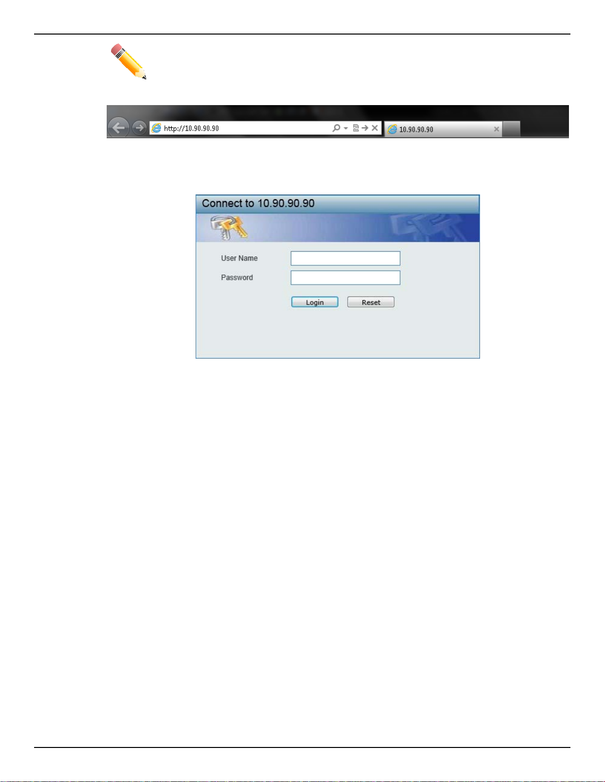
DXS-3600 Series Layer 3 Managed 10Gigabit Ethernet Switch Web UI Reference Guide
NOTE: The default IP address of this switch is 10.90.90.90, with a subnet mask of 255.0.0.0.
Figure 2-1 Displays entering the IP address in Internet Explorer
This will open the user authenticatio n wind o w, as seen bel o w.
Figure 2-2 User Authentication Window
By default, there is no username or password configured on this switch. When connecting to the Web UI
for the first time simply leave the User Name and Password fields blank and click the Login button.
4
Page 16
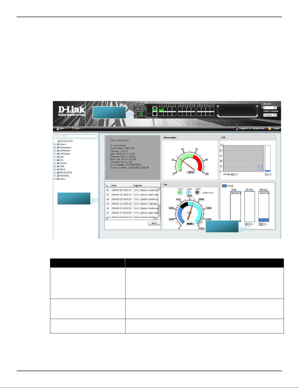
DXS-3600 Series Layer 3 Managed 10Gigabit Ethernet Switch Web UI Reference Guide
AREA 1
AREA 2
AREA 3
Web User Interface (Web UI)
The user interface provides access to various switch configuration and management windows, to view
performance statistics, and permits you to graphically monitor the system status.
Areas of the User Interface
The figure below shows the user interface. Three distinct areas that divide the user interface, as
described in the table.
Figure 2-3 Main Web UI Window
Area Number Description
AREA 1
AREA 2
AREA 3
In this area, a folder tree layout is displayed of functions that can be
configured using the Web UI. Open folders and click the hyperlinked
menu buttons to access each individual page for configuration. The
DXS-3600-32S link is the default page that will display basic
monitoring settings for this switch.
In this area, a graphical near real-time image of the front panel of the
switch is displayed. Some management functions, like Save and Tools
are accessible here.
In this area, the switch’s configuration page can be found, based on
the selection made in AREA 1.
5
Page 17
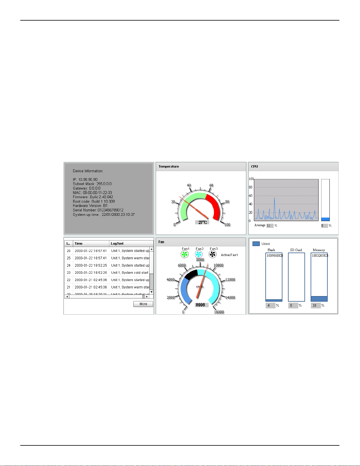
DXS-3600 Series Layer 3 Managed 10Gigabit Ethernet Switch Web UI Reference Guide
3. System
Device Information
System Information Settings
Peripheral Settings
Port Configuration
System Log
Time and SNTP
Time Range
Device Information
On this page, the Device Information, Temperature status, CPU, Usage status, System Log, Fan status,
and Memory usage status are displayed. It appears automatically when you log on to the switch. To
return to the Device Information window after viewin g other w in do ws, clic k the DXS-3600-32S link.
Device Information
In the Device Information section, the user can view a list of basic information regarding the switch.
Figure 3-1 Device Information Window
6
Page 18
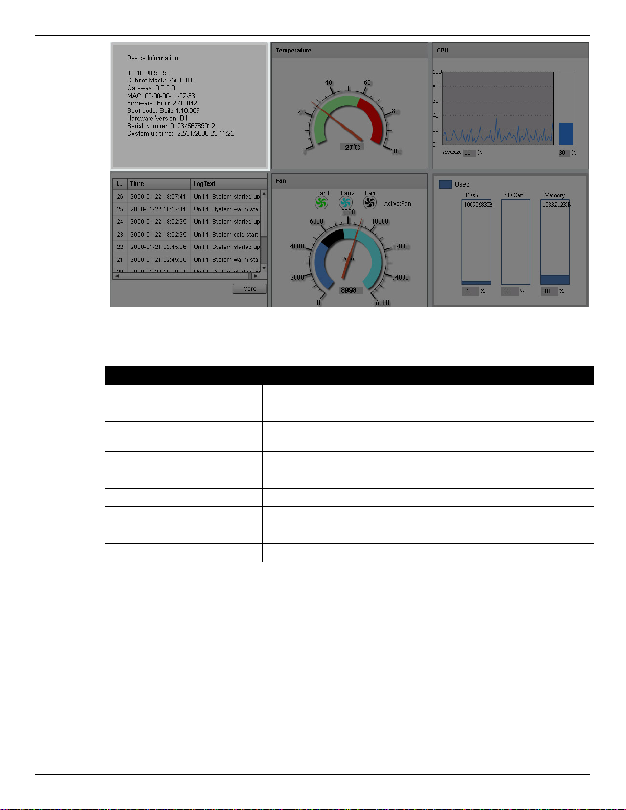
DXS-3600 Series Layer 3 Managed 10Gigabit Ethernet Switch Web UI Reference Guide
Figure 3-2 Device Information (Highlight) Window
In the Device Information section, the following display parameters are available:
Parameter Description
IP Address
Subnet Mask
Gateway
MAC Address
Firmware Version
Boot Code Version
Hardware Version
Serial Number
System Up Time
Temperature Status
In the Temperature section, the user can view a real-time display of the switch’s internal temperature.
The temperature of the switch is mainly influenced by two factors: (1) the environment, and (2) the
internal air-flow of the switch. In the DXS-3600 Seri es Hardware Installation Guide, there are some
guidelines that can ass is t t he us er with t he i ns tal la tio n of this s witc h i n a t emperature friendly environment.
The fan modules, installed in this switch, have temperature sensors built-in that automatically controls the
air-flow inside the switch.
Here the IP address of the switch’s main interface is displayed.
Here the Subnet Mask of the switch’s main interface is displayed.
Here the Gateway IP address of the switch’s main interface is
displayed.
Here the MAC address of the switch is displayed.
Here the Firmware version of the switch is displayed.
Here the Boot Code of the switch is displayed.
Here the Hardware version of the switch is displayed.
Here the Serial number of the switch is displayed.
Here the System’s up time is displayed.
7
Page 19
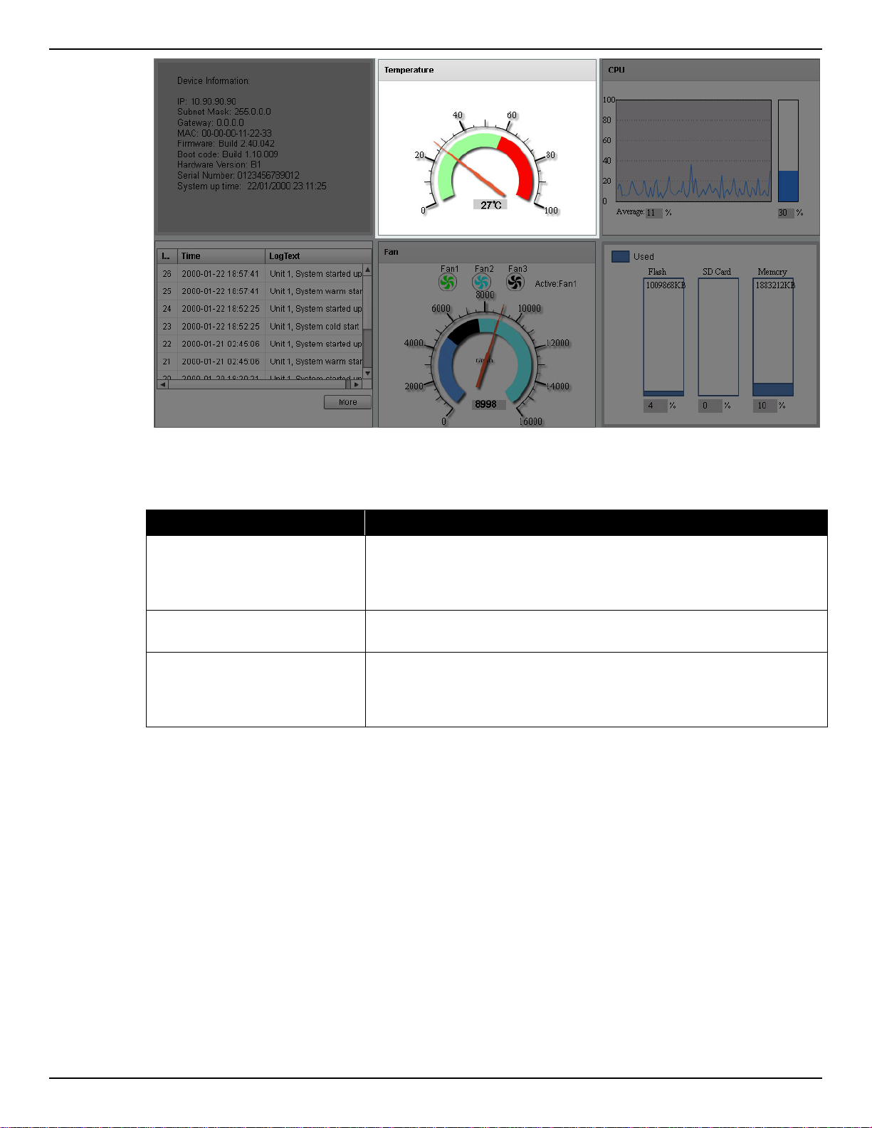
DXS-3600 Series Layer 3 Managed 10Gigabit Ethernet Switch Web UI Reference Guide
Figure 3-3 Temperature Status Window
In the Temperature section, the following display parameters are available:
Parameter Description
Percentage Display
Temperature
Warning Section
CPU Status
In the CPU section, the user can view a real-time display of the switch’s CPU usage. There are a number
of factors that can influence a depleted CPU usage. One of those factors is network broadcasts. In the
DXS-3600 Series CLI Reference Guide ther e is an abundance of features that can be enabled to prevent
this problem from occurring.
In this graphic, the reading is divided into percentage sections. The
green area is known as the ‘safe’ area. This area ranges from 0% to
60%. This is the optimum temperature range recommended for this
switch.
Below the percentage gauge needle, the accurate temperature
reading, for this switch, is displayed in degrees Celsius.
In this graphic, the reading is divided into percentage sections. The
red area is known as the ‘warning’ area. This area ranges from 60% to
100%. It is recommended not to allow the switch to run this hot, to
avoid component damage.
8
Page 20
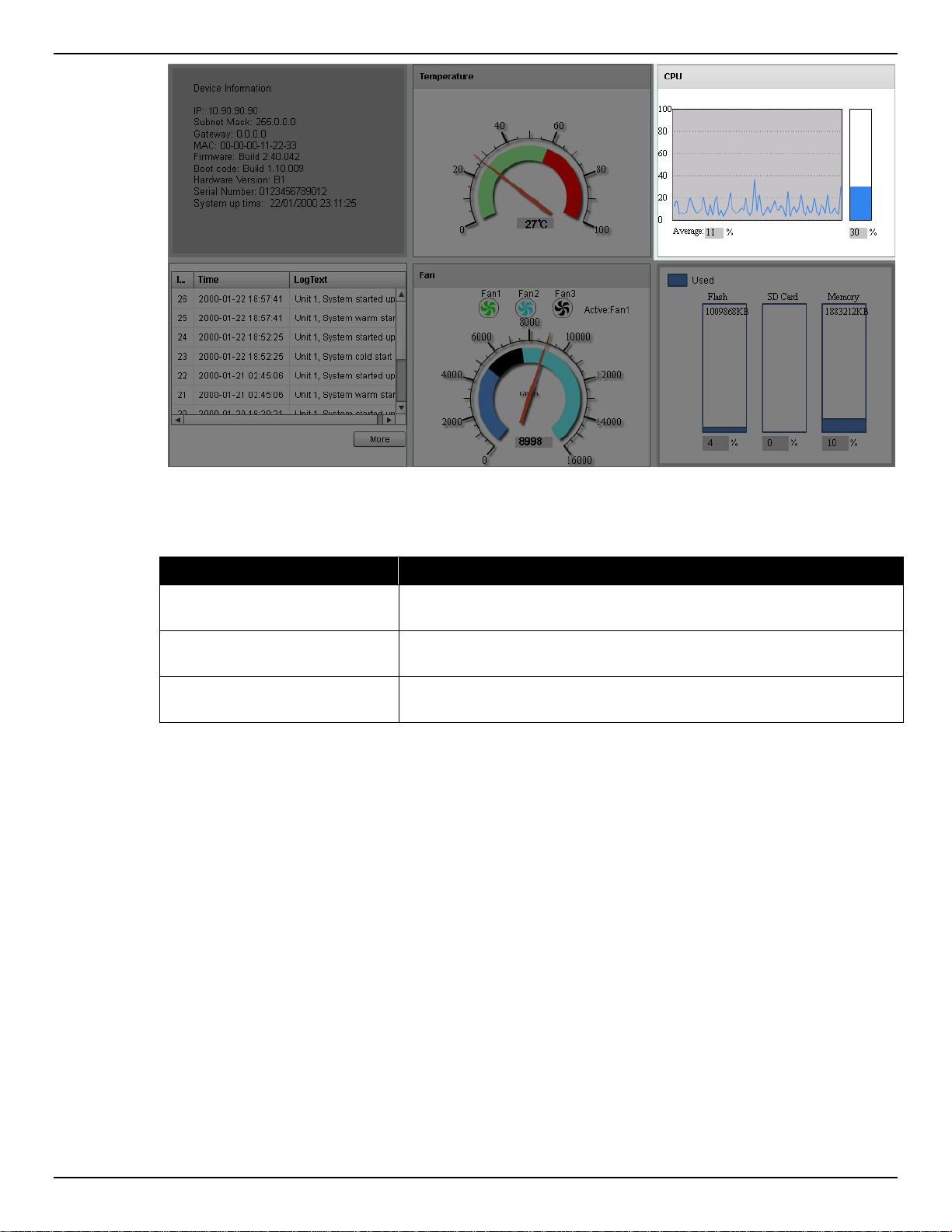
DXS-3600 Series Layer 3 Managed 10Gigabit Ethernet Switch Web UI Reference Guide
Figure 3-4 CPU Status Window
In the CPU section, the following display parameters are available:
Parameter Description
Percentage Display
Average
Percentage Bar
System Log Entries
In the System Log section, the user can view a list of System log entries, generated by the switch, when
certain events have occurred.
In this graphic, the reading is divided into percentage sections. This
area ranges from 0% to 100%.
Below the CPU percentage line chart, we find an accurate display of
the average CPU usage percentage.
In this graphic, an accurate reading of the real-time CPU usage
percentage is displayed.
9
Page 21
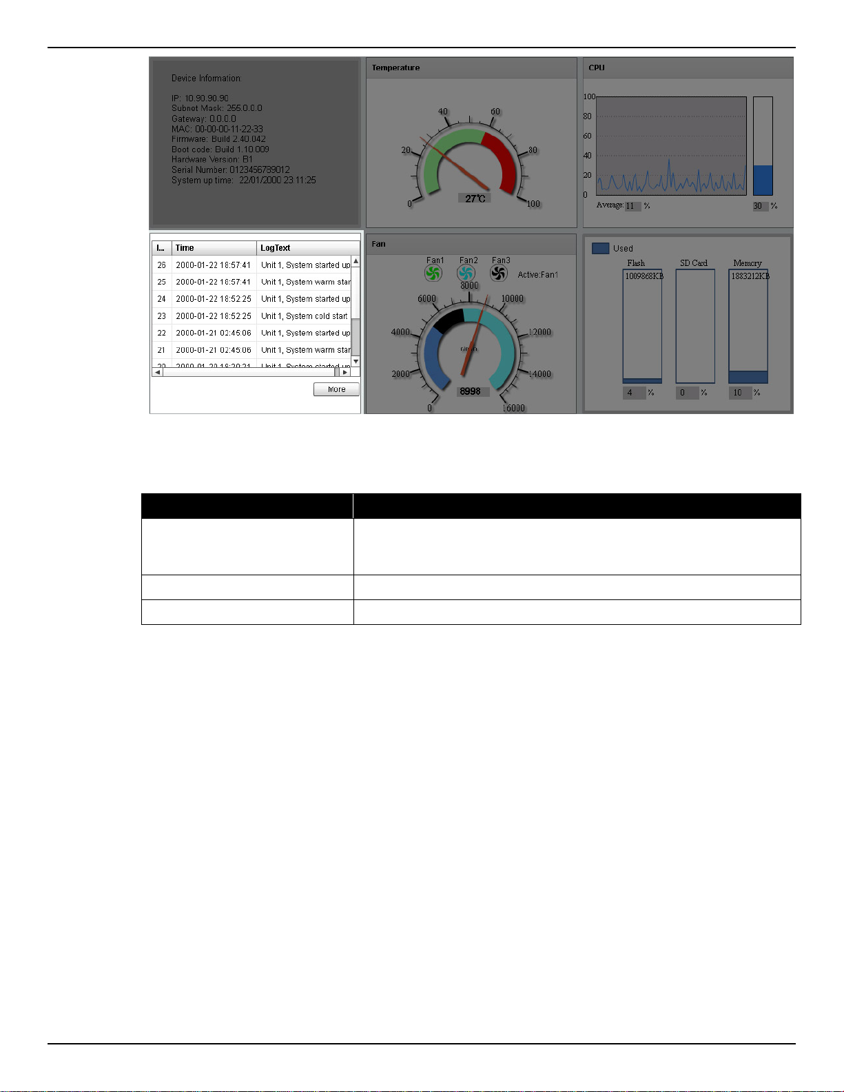
DXS-3600 Series Layer 3 Managed 10Gigabit Ethernet Switch Web UI Reference Guide
Figure 3-5 System Log Window
In the System Log section, the following display parameters are available:
Parameter Description
Entry Number
Every log entry has a specific entry number, generated when the log
entry was added to the System log entry display. Here the System log
entry number is displayed in reverse order.
Time
Log Text
Here the specific date and time of the log entry is displayed.
Here the log entry description is displa yed.
Click the More button to view a larger display of the complete System Log section.
After clicking the More button, the following windo w will appear :
10
Page 22
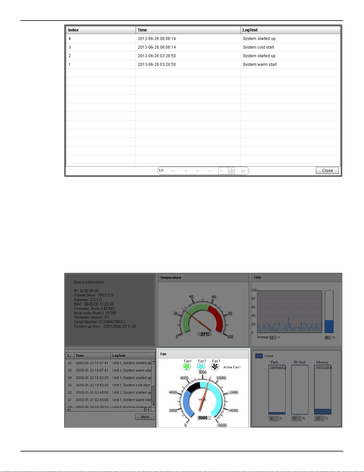
DXS-3600 Series Layer 3 Managed 10Gigabit Ethernet Switch Web UI Reference Guide
Figure 3-6 System Log (More) Window
Click the Close button to exit the larger display.
Fan Status
In the Fan section, the user can view a real-time display of the switch’s fan(s) status. A maximum of 3
fans can be installed in this switch. In this real-time graphic, we observe the status and speed of the three
fans installed.
Figure 3-7 Fan Status Window
11
Page 23
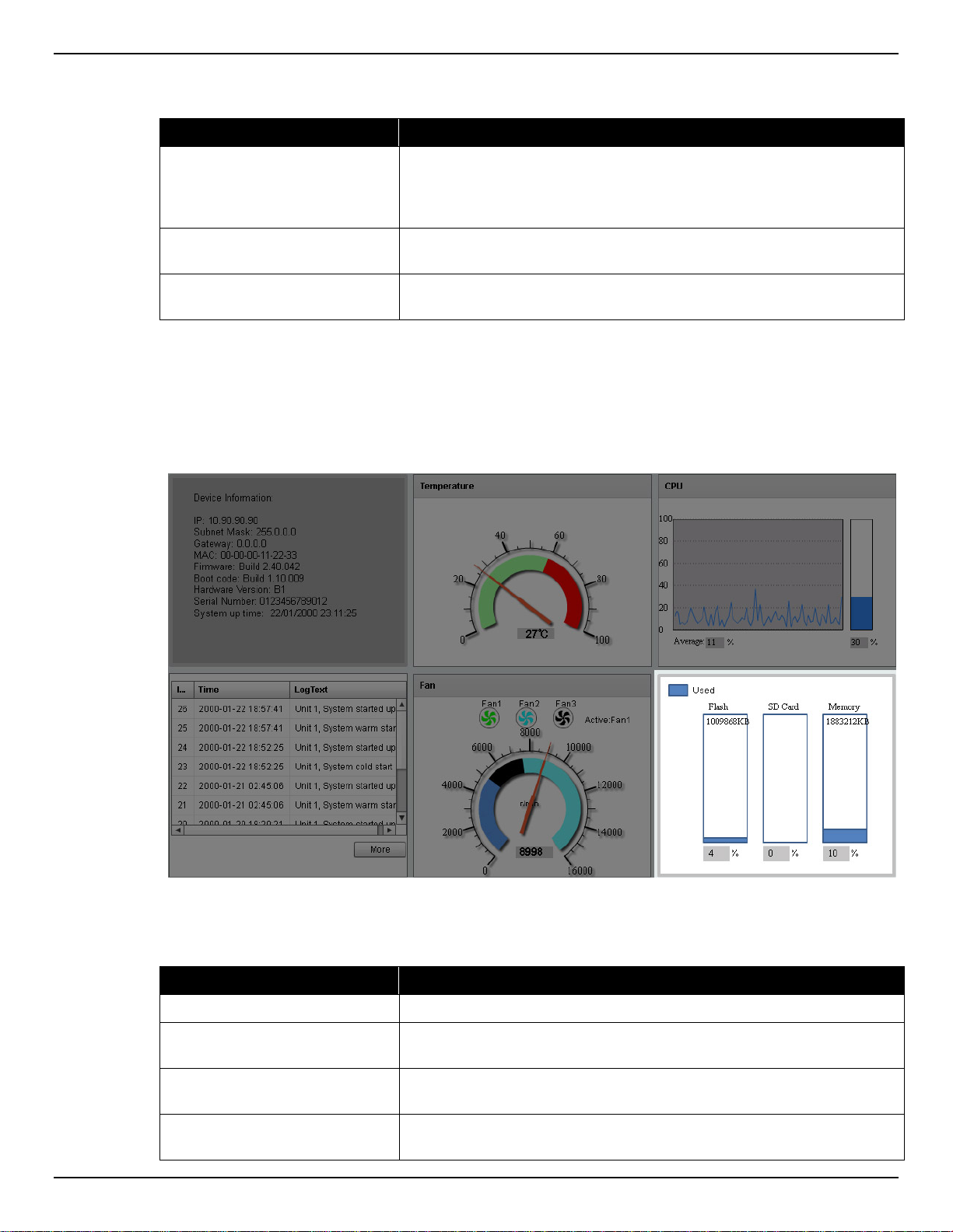
DXS-3600 Series Layer 3 Managed 10Gigabit Ethernet Switch Web UI Reference Guide
In the Fan section, the following display parameters are available:
Parameter Description
Fan Number
RPM Graph
RPM Reading
At the top of this graphic, the list of installed fans is displayed. After
clicking on any specific fan icon, the real-time RPM gauge of that fan
will be displayed. Also after clicking on a fan icon, the Active Fan
display parameter will change accordingly.
In this graph (gauge display), we observe the RPM speed at which the
selected fan is working at.
At the bottom of the graphics, we observe the accurate real-time
display of the RPM value for a specific fan.
Flash, SD Card, and Memory Status
In this section, the user can view a real-time graphic that represents the memory usage for the Flash, SD
Card, and RAM Memory.
Figure 3-8 Flash, SD Card, and Memory Status Window
In this section, the following display parameters are available:
Parameter Description
Used
Flash
SD Card
Memory
This displays the color that represents the used memory allocation.
This displays the used and unused space of the Flash. The more
accurate percentage display can be found below the graphic.
This displays the used and unused space of the SD Card. The more
accurate percentage display can be found below the graphic.
This displays the used and unused space of the Memory. The more
accurate percentage display can be found below the graphic.
12
Page 24
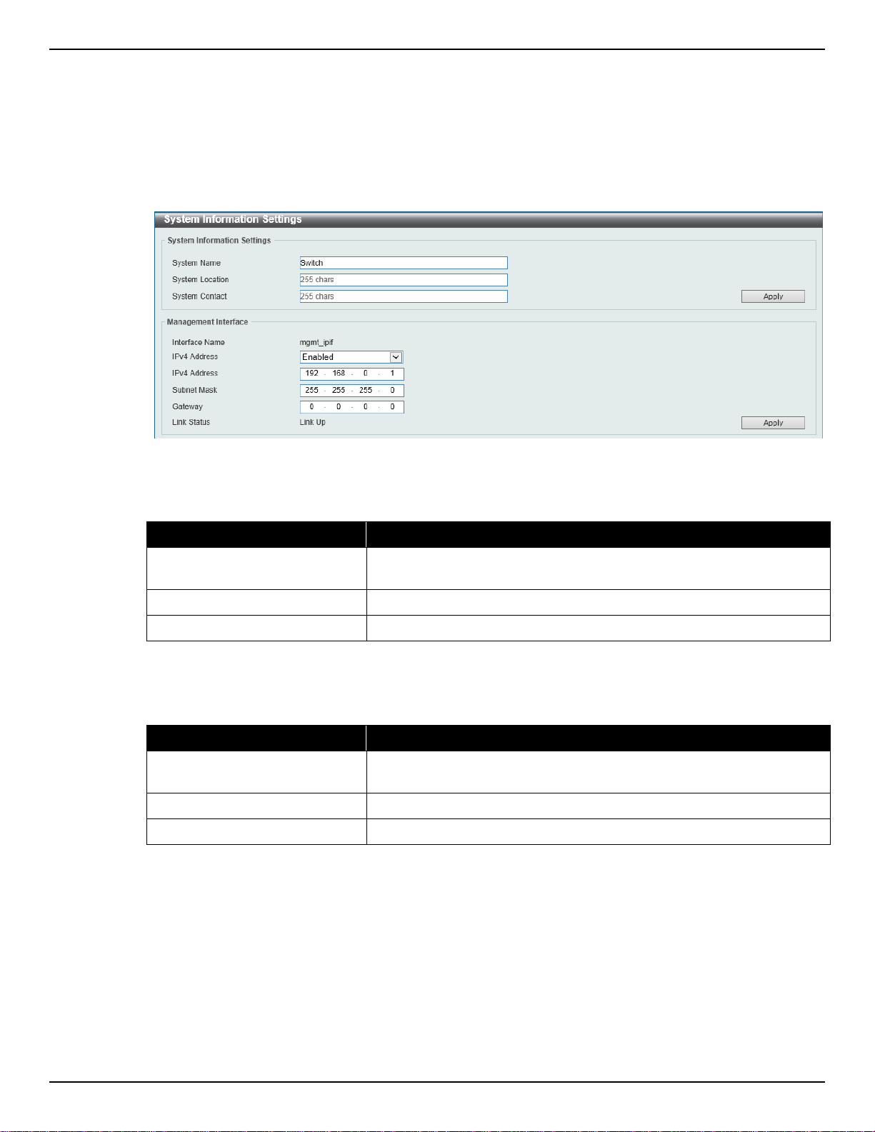
DXS-3600 Series Layer 3 Managed 10Gigabit Ethernet Switch Web UI Reference Guide
System Information Settings
This window is used to view and configure the system information settings and management interface
configuration settings.
To view the following window, click System > System Information Settings, as shown below:
Figure 3-9 System Information Settings Window
The fields that can be configured in System Information Settings are described below:
Parameter Description
System Name
System Location
System Contact
Click the Apply button to accept the changes made.
The fields that can be configured in Management Interface are described below:
Parameter Description
IPv4 Address
Subnet Mask
Gateway
Click the Apply button to accept the changes made.
Enter a system name for the Switch, if so desired. This name will
identify it in the Switch network .
Enter the location of the Switch, if so desired.
Enter a contact name for the Switch, if so desired.
Select to enable or disable this interface here. When enabled, enter
the IPv4 address for this interface here.
Enter the IPv4 subnet mask for this interface here.
Enter the gateway IPv4 address for this interface here.
Peripheral Settings
This window is used to view and configure the environment trap settings and environment temperature
threshold settings.
To view the following window, click System > Peripheral Settings, as shown below:
13
Page 25
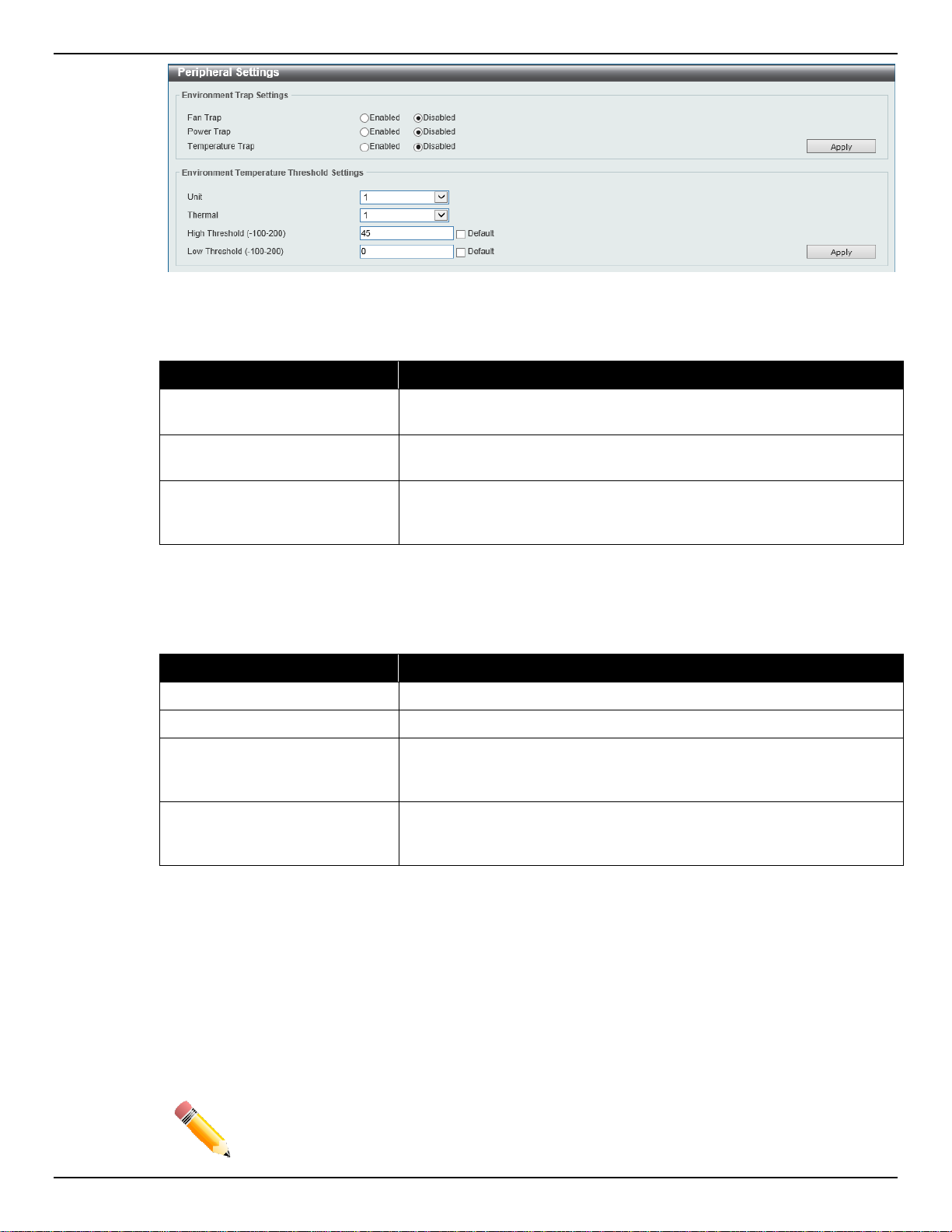
DXS-3600 Series Layer 3 Managed 10Gigabit Ethernet Switch Web UI Reference Guide
Figure 3-10 Peripheral Settings Window
The fields that can be configured in Environment Trap Settings are described below:
Parameter Description
Fan Trap
Power Trap
Temperature Trap
Click the Apply button to accept the changes made.
The fields that can be configured in Environment Temperature Threshold Settings are described
below:
Parameter Description
Unit
Thermal
High Threshold
Low Threshold
Click to enable or disable the fan trap state for waning fan event (fan
failed or fan recover).
Click to enable or disable the power trap state for waning power event
(power failed or power recover).
Click to enable or disable the temperature trap state for warning
temperature event (temperature exceeds the thresholds or
temperature recover).
Select the switch unit that will be used for this configuration here.
Select the thermal sensor ID.
Enter the high threshold value of the warning temperature setting. The
range is from -100 to 200 Celsius degree. Tick the Default check box
to return to the default value.
Enter the low threshold value of the warning temperature setting. The
range is from -100 to 200 Celsius degree. Tick the Default check box
to return to the default value.
Click the Apply button to accept the changes made.
Port Configuration
Port Settings
This window is used to view and configure the switch’s port settings.
NOTE: The 10M and 100M speed options are only applicable when connecting to the
Management Port (Mgmt 0) or when the DXS-3600-EM-8T expansion module is
used.
14
Page 26
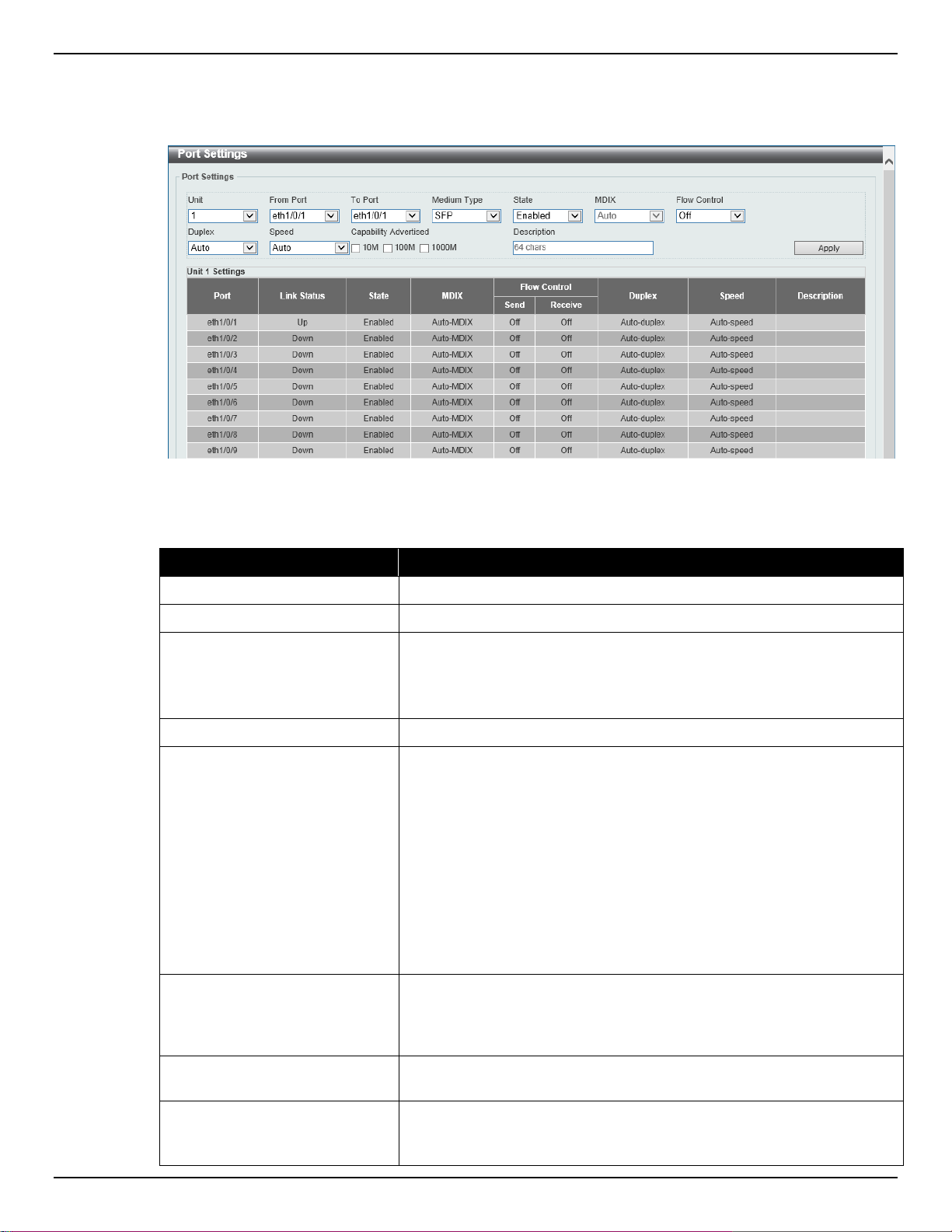
DXS-3600 Series Layer 3 Managed 10Gigabit Ethernet Switch Web UI Reference Guide
cable.
To view the following window, click System > Port Configuration > Port Settings, as shown below:
Figure 3-11 Port Settings Window
The fields that can be configured are described below:
Parameter Description
Unit
From Port ~ To Port
Select the stacking unit ID of the switch that will be configured here.
Select the appropriate port range used for the configuration here.
Medium Type Select the port medium type here. Options to choose from are RJ45
and SFP.
Note: Selecting the SFP option, includes the use of SFP+ transceivers
for 10G connectivity.
State
MDIX
Select this option to enable or disabled the physical port here.
Select the Medium Dependent Interface Crossover (MDIX) option
here. Options to choose from are Auto, Normal, and Cross.
• Auto - Select this option for auto-sensing of the optimal type of
cabling.
• Normal - Select this option for normal cabling. If this option is
selected, the port is in the MDIX mode and can be connected to
a PC’s NIC using a straight-through cable or a port (in the MDI
mode) on another switch through a cross-over cable.
• Cross - Select this option for cross cabling. If this option is
selected, the port is in the MDI mode and can be connected to a
port (in the MDIX mode) on another switch through a straight
Flow Control Select to either turn flow control On or Off here. Ports configured for
full-duplex use 802.3x flow control, half-duplex ports use backpressure flow control, and Auto ports use an automatic selection of the
two.
Duplex Select the duplex mode used here. Options to choose from are Auto,
Half, and Full.
Speed
Select the port speed option here. This option will manually force the
connection speed on the selected port to only connect at the speed
specified here.
15
Page 27

DXS-3600 Series Layer 3 Managed 10Gigabit Ethernet Switch Web UI Reference Guide
Options to choose from are Auto, 10M, 100M, 1000M, 1000M Master,
only available for 40Gbps fiber connections.
Parameter Description
1000M Slave, 10G, 10G Master, 10G Slave, and 40G.
The Master setting will allow the port to advertise capabilities related
to duplex, speed and physical layer type. The master setting will also
determine the master and slave relationship between the two
connected physical layers. This relationship is necessary for
establishing the timing control between the two physical layers. The
timing control is set on a master physica l layer by a local sourc e.
The Slave setting uses loop timing, where the timing comes from a
data stream received from the master. If one connection is set for
master, the other side of the connection must be set for slave. Any
other configuration will result in a link down status for both ports.
• Auto: Specifies that for copper ports, auto-negotiation will start
to negotiate the speed and flow control with its link partner. For
fiber ports, auto-negotiation will start to negotiate the clock and
flow control with its link partner.
• 10M: Specifies to force the port speed to 10Mbps. This option is
only available for 10Mbps copper connections.
• 100M: Specifies to force the port speed to 100Mbps. This option
is only available for 100Mbps copper connections.
• 1000M: Specifies to force the port speed to 1Gbps. This option is
only available for 1Gbps fiber connections.
• 1000M Master: Specifies to force the port speed to 1Gbps and
operates as the master, to facilitate the timing of transmit and
receive operations. This option is only available for 1Gbps
copper connections.
• 1000M Slave: Specifies to force the port speed to 1Gbps and
operates as the slave, to facilitate the timing of transmit and
receive operations. This option is only available for 1Gbps
copper connections.
• 10G: Specifies to force the port speed to 10Gbps. This option is
only available for 10Gbps fiber connections.
• 10G Master: Specifies to force the port speed to 10Gbps and
operates as the master, to facilitate the timing of transmit and
receive operations. This option is only available for 10Gbps
copper connections.
• 10G Slave: Specifies to force the port speed to 10Gbps and
operates as the slave, to facilitate the timing of transmit and
receive operations. This option is only available for 10Gbps
copper connections.
• 40G: Specifies to force the port speed to 40Gbps. This option is
Capability Advertised When the Speed is set to Auto, these capabilities are advertised
Description
Click the Apply button to accept the changes made.
Port Status
This window is used to view the switch’s ph ysical port status and settings.
To view the following window, click System > Port Configuration > Port Status, as shown below:
during auto-negotiation.
Enter a 64 characters description for the corresponding port here.
16
Page 28
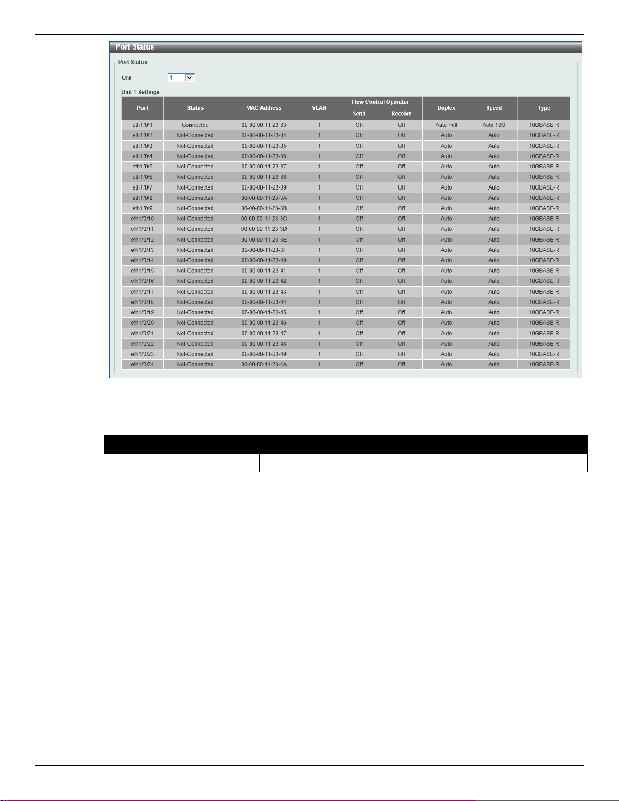
DXS-3600 Series Layer 3 Managed 10Gigabit Ethernet Switch Web UI Reference Guide
The fields that can be configured are described below:
Parameter Description
Unit
Port GBIC
This window is used to view active GBIC information found on each applicable physical port of this switch.
To view the following window, click System > Port Configuration > Port GBIC, as shown below:
Figure 3-12 Port Status Window
Select the stacking unit ID of the switch that will be displayed here.
17
Page 29
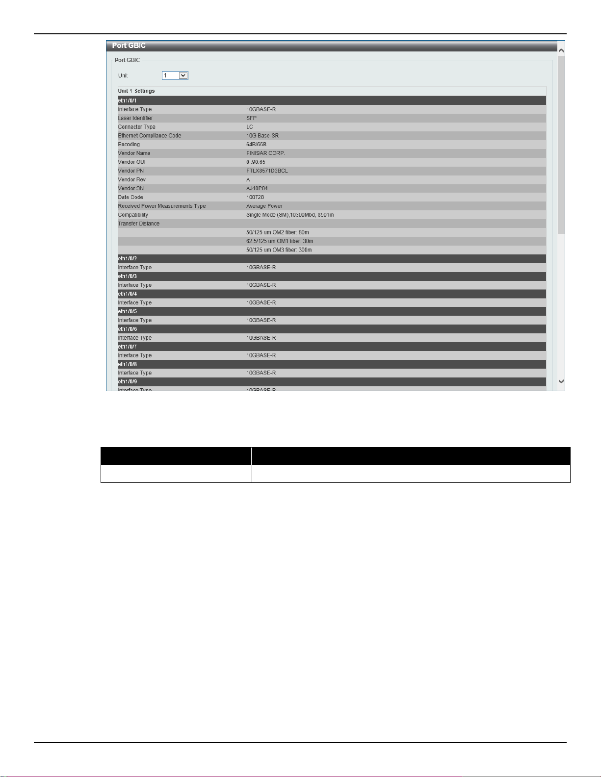
DXS-3600 Series Layer 3 Managed 10Gigabit Ethernet Switch Web UI Reference Guide
The fields that can be configured in Port GBIC are described below:
Parameter Description
Unit
Port Auto Negotiation
This window is used to view detailed port auto-negotiation information.
To view the following window, click System > Port Configuration > Port Auto Negotiation, as shown
below:
Figure 3-13 Port GBIC Window
Select the switch unit that will be used for this display here.
18
Page 30
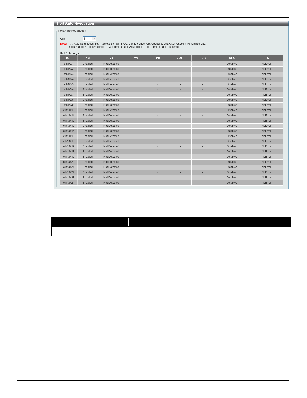
DXS-3600 Series Layer 3 Managed 10Gigabit Ethernet Switch Web UI Reference Guide
Figure 3-14 Port Auto Negotiation Window
The fields that can be configured are described belo w:
Parameter Description
Unit
Error Disable Settings
This window is used to view and configure the error recovery for causes and to configure the recovery
interval.
To view the following window, click System > Port Configuration > Error Disable Settings, as shown
below:
Select the stacking unit ID of the switch that will be displayed here.
19
Page 31

DXS-3600 Series Layer 3 Managed 10Gigabit Ethernet Switch Web UI Reference Guide
Figure 3-15 Error Disable Settings Window
The fields that can be configured in Error Disable Recovery Settings are described belo w:
Parameter Description
ErrDisable Cause Select the error disabled cause here. Options to choose from are Port
Security, Storm Control, BPDU Attack Protection, Dynamic ARP
Inspection, DHCP Snooping, and Loopback Detect.
State
Interval
Click the Apply button to accept the changes made.
Jumbo Frame
This window is used to view and configure the Jumbo Frame size and settings. The switch supports
jumbo frames. Jumbo frames are Ethernet frames with more than 1,518 bytes of payload. The switch
supports jumbo frames with a maximum frame size of up to 12288 bytes.
To view the following window, click System > Port Configuration > Jumbo Frame, as shown below:
Select the enable or disable the error disabled recovery feature here.
Enter the time, in seconds, to recover the port from the error state
caused by the specified module. The range is from 5 to 86400.
20
Page 32

DXS-3600 Series Layer 3 Managed 10Gigabit Ethernet Switch Web UI Reference Guide
The fields that can be c onf i gur ed are des c ribed be lo w:
Parameter Description
Unit
From Port ~ To Port
Maximum Receive Frame Size
Click the Apply button to accept the changes made.
System Log
System Log Settings
This window is used to view and configure the system’s log settings.
To view the following window, click System > System Log > System Log Settings, as shown below:
Figure 3-16 Jumbo Frame Window
Select the stacking unit ID of the switch that will be configured here.
Select the appropriate port range used for the configuration here.
Enter the maximum receive frame size value here. This value must be
between 64 and 12288 bytes. By default, this value is 1536 bytes.
21
Page 33

DXS-3600 Series Layer 3 Managed 10Gigabit Ethernet Switch Web UI Reference Guide
Options to choose from are 0 (Emergencies), 1 (Alerts), 2 (Critical),
Figure 3-17 System Log Settings Window
The fields that can be configured for Log State are described below:
Parameter Description
Log State
Select the enable or disable the system log feature’s global state here.
Click the Apply button to accept the changes made.
The fields that can be configured for Source Interface Settings are described belo w:
Parameter Description
Source Interface State
Select this option to enable or disable the source interface’s global
state.
Type
Select the type of interface that will be used. Options to choose from
are Loopback, Mgmt, and VLAN.
VID
Enter the interface’s VID used here. For loopback interfaces this ID
can be from 1 to 8. For the management (Mgmt) interface this value is
always 0. For VLAN interfaces this value is from 1 to 4094.
Click the Apply button to accept the changes made.
The fields that can be configured for Buffer Log Settings are described below:
Parameter Description
Buffer Log State
Select whether the enable or disable the buffer log’s global state here.
Options to choose from are Enable, Disabled, and Default. When
selecting the Default option, the buffer log’s global state will follow the
default behavior.
Severity
Select the severity value of the type of information that will be logged.
22
Page 34

DXS-3600 Series Layer 3 Managed 10Gigabit Ethernet Switch Web UI Reference Guide
3 (Errors), 4 (Warnings), 5 (Notifications), 6 (Informational), and 7
Parameter Description
(Debugging).
Discriminator Name
Write Delay
Click the Apply button to accept the changes made.
The fields that can be configured for Console Log Settings are described below:
Parameter Description
Console Log State
Severity
Discriminator Name
Click the Apply button to accept the changes made.
Enter the discriminator name used here. This name can be up to 15
characters long.
Enter the log’s write delay value here. This value must be between 0
and 65535 seconds. By default, this value is 300 seconds. Tick the
Infinite option, to disable the write delay feature.
Select whether the enable or disable the console log’s global state
here.
Select the severity value of the type of information that will be logged.
Options to choose from are 0 (Emergencies), 1 (Alerts), 2 (Critical),
3 (Errors), 4 (Warnings), 5 (Notifications), 6 (Informational), and 7
(Debugging).
Enter the discriminator name used here. This name can be up to 15
characters long.
The fields that can be configured for SMTP Log Settings are described below:
Parameter Description
SMTP Log State
Severity
Discriminator Name
Click the Apply button to accept the changes made.
Select whether the enable or disable the SMTP log’s global state here.
Select the severity value of the type of information that will be logged.
Options to choose from are 0 (Emergencies), 1 (Alerts), 2 (Critical),
3 (Errors), 4 (Warnings), 5 (Notifications), 6 (Informational), and 7
(Debugging).
Enter the discriminator name used here. This name can be up to 15
characters long.
System Log Discriminator Settings
This window is used to view and configure the system log’s discriminator settings.
To view the following window, click System > System Log > System Log Discriminator Settings, as
shown below:
23
Page 35

DXS-3600 Series Layer 3 Managed 10Gigabit Ethernet Switch Web UI Reference Guide
Figure 3-18 System Log Discriminator Settings Window
The fields that can be configured are described below:
Parameter Description
Discriminator Name
Action
Severity
Click the Apply button to accept the changes made.
Click the Delete button to delete the specified entry.
Enter the discriminator name here. This name can be up to 15
characters long.
Select the facility’s behavior option and the type of facility that will be
associated with the selected behavior here. Behavior options to
choose from are Drops and Includes.
Select the severity behavior option and the value of the type of
information that will be logged. Behavior options to choose from are
Drops and Includes. Severity value options to choose from are 0
(Emergencies), 1 (Alerts), 2 (Critical), 3 (Errors), 4 (Warnings), 5
(Notifications), 6 (Informational), and 7 (Debugging).
System Log Server Settings
This window is used to view and configure system log’s server settings.
To view the following window, click System > System Log > System Log Server Settings, as shown
below:
24
Page 36

DXS-3600 Series Layer 3 Managed 10Gigabit Ethernet Switch Web UI Reference Guide
Figure 3-19 System Log Server Settings Window
The fields that can be configured are described below:
Parameter Description
Host IPv4 Address
Host IPv6 Address
UDP Port
Severity
Facility
Discriminator Name
VRF Name
Click the Apply button to accept the changes made.
Click the Delete button to delete the specified entry.
System Log
This window is used to view and clear the system log.
Enter the system log server’s IPv4 address here.
Enter the system log server’s IPv6 address here.
Enter the system log server’s UDP port number here. This value must
be between 1024 and 65535. By default, this value is 514.
Select the severity value of the type of information that will be logged.
Options to choose from are 0 (Emergencies), 1 (Alerts), 2 (Critical),
3 (Errors), 4 (Warnings), 5 (Notifications), 6 (Informational), and 7
(Debugging).
Select the facility value here. Options to choose from are 0 to 23.
Enter the discriminator name here. This name can be up to 15
characters long.
Enter the VRF name that will be associated with th is conf igurat io n
here.
To view the following window, click System > System Log > System Log, as shown below:
Figure 3-20 System Log Window
Click the Clear Log button to clear the system log entries displayed in the table.
25
Page 37

DXS-3600 Series Layer 3 Managed 10Gigabit Ethernet Switch Web UI Reference Guide
System Attack Log
This window is used to view and clear the system attack log.
To view the following window, click System > System Log > System Attack Log, as shown below:
The fields that can be configured are described below:
Parameter Description
Figure 3-21 System Attack Log Window
Unit
Click the Clear Attack Log button to clear the system attack log entries displayed in the table.
Time and SNTP
Clock Settings
This window is used to view and configure the time settings for the Switch.
To view the following window, click System > Time and SNTP > Clock Settings, as shown below:
The fields that can be configured in Clock Settings are described below:
Select the stacking unit ID of the switch that will be displayed here.
Figure 3-22 Clock Settings Window
Parameter Description
Time
Date
Click the Apply button to accept the changes made.
Time Zone Settings
This window is used to view and configure time zones and Daylight Savings Time settings for SNTP.
Enter the current time in hours (HH), minutes (MM), and seconds (SS)
here. For example, 18:30:30.
Enter the current day (DD), month (MM), and year (YY) here. For
example, 30/04/2015.
26
Page 38

DXS-3600 Series Layer 3 Managed 10Gigabit Ethernet Switch Web UI Reference Guide
start and end on the specified date of the specified month.
To view the following window, click System > Time and SNTP > Time Zone Settings, as shown below:
Figure 3-23 Time Zone Settings Window
The fields that can be configured are described below:
Parameter Description
Summer Time State Select the summer time setting. Options to choose from are Disabled,
Recurring Setting, and Date Setting.
• Disabled - Select to disable the summer time setting.
• Recurring Setting - Select to configure the summer time that
should start and end on the specified week day of the specified
month.
• Date Setting - Select to configure the summer time that should
Time Zone
Select to specify your local time zone’s offset from Coordinated
Universal Time (UTC).
The fields that can be configured in Recurring Settings are described below:
Parameter Description
From: Week of the Month
Select week of the month that summer time will start.
From: Day of the Week
From: Month
From: Time
To: Week of the Month
Select the day of the week that summer time will start.
Select the month that summer time will start.
Select the time of the day that summer time will start.
Select week of the month that summer time will end.
27
Page 39

DXS-3600 Series Layer 3 Managed 10Gigabit Ethernet Switch Web UI Reference Guide
Parameter Description
To: Day of the Week
To: Month
To: Time
Offset
The fields that can be configured in Date Settings are described below:
Parameter Description
From: Date of the Month
From: Month
From: Year
From: Time
To: Date of the Month
To: Month
To: Year
To: Time
Offset
Select the day of the week that summer time will end.
Select the month that summer time will end.
Select the time of the day that summer time will end.
Enter the number of minutes to add during summer time. The default
value is 60. The range of this offset is 30, 60, 90 and 120.
Select date of the month that summer time will start.
Select the month that summer time will start.
Enter the year that the summer time will start.
Select the time of the day that summer time will start.
Select date of the month that summer time will end.
Select the month that summer time will end.
Enter the year that the summer time will end.
Select the time of the day that summer time will end.
Enter the number of minutes to add during summer time. The default
value is 60. The range of this offset is 30, 60, 90 and 120.
Click the Apply button to accept the changes made.
SNTP Settings
This window is used to view configure the SNTP settings for the switch.
To view the following window, click System > Time and SNTP > SNTP Settings, as shown below:
Figure 3-24 SNTP Settings Window
The fields that can be configured in SNTP Global Settings are described below:
Parameter Description
SNTP State
Poll Interval
Select this option to enable or disable SNTP.
Enter the synchronizing interval in seconds. The value is from 30 to
28
Page 40

DXS-3600 Series Layer 3 Managed 10Gigabit Ethernet Switch Web UI Reference Guide
99999 seconds. The default interval is 720 seconds.
Parameter Description
Click the Apply button to accept the changes made.
The fields that can be configured in SNTP Server Settings are described below:
Parameter Description
IPv4 Address
VRF Name
Click the Add button to add the SNTP server.
Click the Delete button to remove the specified entry.
Time Range
This window is used to view and configure the time profile settings.
To view the following window, click System > Time Range, as shown below:
Enter the IP address of the SNTP server which provides the clock
synchronization.
Enter the name of the VRF instance which the SNTP server belongs
to.
Figure 3-25 Time Range Window
The fields that can be configured are described below:
Parameter Description
Range Name
From Week ~ To Week
From Time ~ To Time
Click the Apply button to accept the changes made.
Click the Find button to locate a specific entry based on the information entered.
Enter the time profile’s range name here. This name can be up to 32
characters long.
Select the starting and ending days of the week that will be used for
this time profile. Tick the Daily option to use this time profile for every
day of the week. Tick the End Week Day option to use this time profile
from the starting day of the week until the end of the week, which is
Sunday.
Select the starting and ending time of the day that will be used for this
time profile. The first drop-down menu selects the hour and the second
drop-down menu selects the minute.
29
Page 41

DXS-3600 Series Layer 3 Managed 10Gigabit Ethernet Switch Web UI Reference Guide
Click the Delet e Per iod ic b utton to delete the periodic entry.
Click the Delete button to delete the specified entry.
30
Page 42

DXS-3600 Series Layer 3 Managed 10Gigabit Ethernet Switch Web UI Reference Guide
4. Management
User Account Settings
Password Encryption
Login Method
SNMP
RMON
Telnet/Web
Session Timeout
DHCP
DHCP Auto Configuration
DNS
IP Source Interface
File System
Physical Stacking
Virtual Stacking (SIM)
SMTP Settings
NLB FDB Settings
User Account Settings
On this page, user accounts can be created and configured. Also on this page active user account
sessions can be viewed.
There are several configuration options available in the Web User Interface (Web UI). The set of
configuration options avai la ble to the user dep ends on t he accou nt’s Privilege Level.
NOTE: By default, there is no user account created on this switch.
To view the following window, click Management > User Account Settings, as shown below:
After selecting the User Management Settings tab, the following page will appear.
Figure 4-1 User Management Settings Window
The fields that can be configured are described below:
Parameter Description
User Name
Privilege
Enter the user account name here. This name can be up to 32
characters long.
Enter the privilege level for this account here. This value must be
31
Page 43

DXS-3600 Series Layer 3 Managed 10Gigabit Ethernet Switch Web UI Reference Guide
between 1 and 15.
Parameter Description
Password Type
Password After selecting either Plain Text or Encrypted as the password type,
Click the Apply button to accept the changes made.
Click the Delete button to delete the specified user account entry.
After selecting the Session Table tab, the following page will appear.
On this page, a list of active user account session will be displayed.
Select the password type for this user account here. Options to choose
from are None, Plain Text, and Encrypted.
enter the password for this user account here.
Figure 4-2 Session Table Window
Password Encryption
This window is used to view and configure whether to save the encryption of the password in the
configuration file.
To view the following window, click Management > Password Encryption, as shown below:
Figure 4-3 Password Encryption Window
The fields that can be configured in Password Encryption Settings are described below:
Parameter Description
Password Encryption State
Click the Apply button to accept the changes made.
Login Method
Select this option to enable or disable the encryption of the password
before stored in the configuration file.
This window is used to view and configure the login method for each management interface that this
Switch supports.
To view the following window, click Management > Login Method, as shown below:
32
Page 44

DXS-3600 Series Layer 3 Managed 10Gigabit Ethernet Switch Web UI Reference Guide
Figure 4-4 Login Method Window
The Login Method section will only be available when Authentication, Authorization, and Accounting
(AAA) feature is disabled. The fields that can be configured in Login Method are described below:
Parameter Description
Login Method After clicking the Edit button this parameter can be configured. Select
the login method for the specified application here. Options to choose
from are No Login, Login and Login Local. No Login, as the name
implies, requires no login authentication to access the specified
application. Login will require the user to at least enter a password
when trying to access the application specified. Login Local requires
the user to enter a username and a password to access the specified
application.
SNMP
The fields that can be configured in Login Password are described below:
Parameter Description
Application
Password Type
Password
Click the Apply button to accept the changes made.
Click the Delete button to remove the password from the specified application.
Simple Network Management Protocol (SNMP) is an OSI Layer 7 (Application Layer) designed
specifically for managing and monitoring network devices. SNMP enables network management stations
to read and modify the settings of gateways, routers, switches, and other network devices. Use SNMP to
configure system features for proper operation, monitor performance and detect potential problems in the
Switch, switch group or network.
Select the application that will be configured here. Options to choose
from are Console, Telnet and SSH.
Select the password encryption type that will be used here. Options to
choose from are Plain Text and Encrypted.
Enter the password for the selected application here. This password
will be used when the Login Method for the specified application is set
as Login.
Managed devices that support SNMP include software (referred to as an agent), which runs locally on the
device. A defined set of variables (managed objects) is maintained by the SNMP agent and used to
manage the device. These objects are defined in a Management Information Base (MIB), which provides
33
Page 45

DXS-3600 Series Layer 3 Managed 10Gigabit Ethernet Switch Web UI Reference Guide
a standard presentation of the information controlled by the on-board SNMP agent. SNMP defines both
the format of the MIB specifications and the protocol used to access this information over the network.
The Switch supports the SNMP versions 1, 2c, and 3. The three versions of SNMP vary in the level of
security provided between the management station and the network device.
In SNMP v.1 and v.2, user authentication is accomplished using ‘community strings’, which function like
passwords. The remote user SNMP application and the Switch SNMP must use the same community
string. SNMP packets from any station that has not been authenticated are ignored (dropped).
The default community strings for the Switch used for SNMP v.1 and v.2 management access are:
• public - Allows authorized management stations to retrieve MIB objects.
• private - Allows authorized management stations to retrieve and modify MIB objects.
SNMPv3 uses a more sophisticated authentication process that is separated into two parts. The first part
is to maintain a list of users and their attributes that are allowed to act as SNMP managers. The second
part describes what each user on that list can do as an SNMP manager.
The Switch allows groups of users to be listed and configured with a shared set of privileges. The SNMP
version may also be set for a listed group of SNMP managers. Thus, you may create a group of SNMP
managers that are allowed to view read-only information or receive traps using SNMPv1 while assigning
a higher level of security to another group, granting read/write privileges using SNMPv3.
Using SNMPv3 individual users or groups of SNMP managers can be allowed to perform or be restricted
from performing specific SNMP management functions. The functions allowed or restricted are defined
using the Object Identifier (OID) associated with a specific MIB. An additional layer of security is available
for SNMPv3 in that SNMP messages may be encrypted. To read more about how to configure SNMPv3
settings for the Switch read the next section.
Traps
Traps are messages that alert network personnel of events that occur on the Switch. The events can be
as serious as a reboot (someone accidentally turned OFF the Switch), or less serious like a port status
change. The Switch generates traps and sends them to the trap recipient (or network manager). Typical
traps include trap messages for Authentication Failure, Topology Change and Broadcast\Multicast Storm.
MIBs
The Switch in the Management Information Base (MIB) stores management and counter information. The
Switch uses the standard MIB-II Management Information Base module. Consequently, values for MIB
objects can be retrieved from any SNMP-based network management software. In addition to the
standard MIB-II, the Switch also supports its own proprietary enterprise MIB as an extended Management
Information Base. Specifying the MIB Object Identifier may also retrieve the proprietary MIB. MIB values
can be either read-only or read-write.
The Switch incorporates a flexible SNMP management for the switching environment. SNMP
management can be customized to suit the needs of the networks and the preferences of the network
administrator. Use the SNMP V3 menus to select the SNMP version used for specific tasks.
The Switch supports the Simple Network Management Protocol (SNMP) versions 1, 2c, and 3. The
administrator can specify the SNMP version used to monitor and control the Switch. The three versions
of SNMP vary in the level of security provided between the management station and the network device.
34
Page 46

DXS-3600 Series Layer 3 Managed 10Gigabit Ethernet Switch Web UI Reference Guide
SNMP settings are configured using the menus located on the SNMP V3 folder of the Web manager.
Workstations on the network that are allowed SNMP privileged access to the Switch can be restricted with
the Management Station IP Address menu.
SNMP Global Settings
This window is used to view and configure the SNMP global settings and trap settings.
To view the following window, click Management > SNMP > SNMP Global Settings, as shown below:
Figure 4-5 SNMP Global Settings Window
The fields that can be configured in SNMP Global Settings are described below:
Parameter Description
SNMP Global State
SNMP Response Broadcast
Request
SNMP UDP Port
Trap Source Interface
The fields that can be configured in Trap Settings are described below:
Parameter Description
Trap Global State
SNMP Authentication Trap
Select this option to enable or disable the SNMP feature.
Select this option to enable or disable the server to response to
broadcast SNMP GetRequest packets.
Enter the SNMP UDP port number.
Enter the interface whose IP address will be used as the source
address for sending the SNMP trap packet.
Select this option to enable or disable the sending of all or specific
SNMP notifications.
Tick this option to control the sending of SNMP authentication failure
notifications. An authenticat ionF a i luretrap is generated when the
device receives an SNMP message that is not properly authenticated.
The authentication method depends on the version of SNMP being
used. For SNMPv1 or SNMPv2c, authentication failure occurs if
packets are formed with an incorrect community string. For SNMPv3,
authentication failure occurs if packets are formed with an incorrect
SHA/MD5 authentication key.
Port Link Up
Tick this option to control the sending of port link up notifications. A
linkup trap is generated when the device recognizes that one of the
communication links has come up.
35
Page 47

DXS-3600 Series Layer 3 Managed 10Gigabit Ethernet Switch Web UI Reference Guide
Parameter Description
Port Link Down
Coldstart
Warmstart
Click the Apply button to accept the changes made.
Tick this option to control the sending of port link down notificat ions. A
linkDown trap is generated when the de vice rec ogn i ze s a failure in one
of the communication links.
Tick this option to control the sending of SNMP coldStart notifications.
Tick this option to control the sending of SNMP warmStart
notifications.
SNMP Linkchange Trap Settings
This window is used to view and configure the SNMP link change trap settings.
To view the following window, click Management > SNMP > SNMP Linkchange Trap Settings, as
shown below:
Figure 4-6 SNMP Linkchange Trap Settings Window
The fields that can be configured in SNMP Linkchange Trap Settings are described below:
Parameter Description
Unit
From Port ~ To Port
Trap Sending
Trap State
Click the Apply button to accept the changes made.
Select the switch unit that will be used for this configuration here.
Select the appropriate port range used for the configuration here.
Select this option to enable or disable the sending of the SNMP
notification traps that is generated by the system.
Select this option to enable or disable the SNMP link change trap.
SNMP View Table Settings
This window is used to assign views to community strings that define which MIB objects can be accessed
by a remote SNMP manager. The SNMP Group created with this table maps SNMP users (identified in
the SNMP User Table) to the views created in the previous window.
To view the following window, click Management > SNMP > SNMP View Table Settings, as shown
below:
36
Page 48

DXS-3600 Series Layer 3 Managed 10Gigabit Ethernet Switch Web UI Reference Guide
that an SNMP manager can access.
Figure 4-7 SNMP View Table Settings Window
The fields that can be configured in SNMP View Settings are described below:
Parameter Description
View Name
Subtree OID
View Type Select the view type here. Options to choose from are Included, and
Click the Add button to add a new entry based on the information entered.
Click the Delete button to remove the specified entry.
Type an alphanumeric string of up to 32 characters. This is used to
identify the new SNMP view being created .
Type the Object Identifier (OID) sub-tree for the view. The OID
identifies an object tree (MIB tree) that will be included or excluded
from access by an SNMP manager.
Excluded.
• Included - Select to include this object in the list of objects that
an SNMP manager can access.
• Excluded - Select to exclude this object from the list of objects
SNMP Community Table Settings
This window is used to create an SNMP community string to define the relationship between the SNMP
manager and an agent. The community string acts like a password to permit access to the agent on the
Switch. One or more of the following characteristics can be associated with the community string:
• An Access List of IP addresses of SNMP managers that are permitted to use the community string
to gain access to the Switch’s SNMP agent.
• Any MIB view that defines the subset of all MIB objects will be accessible to the SNMP community.
• Read/write or read-only level permission for the MIB objects accessible to the SNMP community.
To view the following window, click Management > SNMP > SNMP Community Table Settings, as
shown below:
37
Page 49

DXS-3600 Series Layer 3 Managed 10Gigabit Ethernet Switch Web UI Reference Guide
MIBs on the Switch.
Figure 4-8 SNMP Community Table Settings Window
The fields that can be configured in SNMP Community Settings are described below:
Parameter Description
Key Type
Community Name
View Name
Access Right Select the access right here. Options to choose from are Read Only,
IP Access-List Name
Click the Add button to add a new entry based on the information entered.
Click the Delete button to remove the specified entry.
Select the key type for the SNMP community. Options to choose from
are Plain Text, and Encrypted.
Enter an alphanumeric string of up to 32 characters that is used to
identify members of an SNMP community. This string is used like a
password to give remote SNMP managers access to MIB objects in
the Switch’s SNMP agent.
Enter an alphanumeric string of up to 32 characters that is used to
identify the group of MIB objects that a remote SNMP manager is
allowed to access on the Switch. The view name must exist in the
SNMP View Table.
and Read Write.
• Read Only - SNMP community members using the community
string created can only read the contents of the MIBs on the
Switch.
• Read Write - SNMP community members using the community
string created can read from, and write to the contents of the
Enter the name of the standard access list to control the user to use
this community string to access to the SNMP agent.
SNMP Group Table Settings
An SNMP Group created with this table maps SNMP users (identified in the SNMP User Table) to the
views created in the previous window.
To view the following window, click Management > SNMP > SNMP Group Table Settings, as shown
below:
38
Page 50

DXS-3600 Series Layer 3 Managed 10Gigabit Ethernet Switch Web UI Reference Guide
security model.
will be encrypted.
Figure 4-9 SNMP Group Table Settings Window
The fields that can be configured in SNMP Group Settings are described below:
Parameter Description
Group Name
Enter the group name of a maximum of 32 characters. The syntax is
general string that does not allow space.
Read View Name
Enter the read view name that the group user can access.
User-based Security Model Select the security model here. Options to choose from are SNMPv1,
SNMPv2c, and SNMPv3.
• SNMPv1 - Select to allow the group user to use the SNMPv1
security model.
• SNMPv2c - Select to allow the group user to use the SNMPv2c
security model.
• SNMPv3 - Select to allow the group user to use the SNMPv3
Write View Name
Enter the write view name that the group user can access.
Security Level When selecting SNMPv3 in the User-based Security Model drop-
down list, this option is available.
• NoAuthNoPriv - Specify that there will be no authorization and
no encryption of packets sent between the Switch and a remote
SNMP manager.
• AuthNoPriv - Specify that authorization will be required, but
there will be no encryption of packets sent between the Switch
and a remote SNMP manager.
• AuthPriv - Specify that authorization will be required, and that
packets sent between the Switch and a remote SNMP manger
Notify View Name
Enter a write view name that the group user can access. The notify
view describes the object that can be reported its status via trap
packets to the group user.
IP Address-List Name
Enter the standard IP access control list (ACL) to associate with the
group.
Click the Add button to add a new entry based on the information entered.
Click the Delete button to remove the specified entry.
39
Page 51

DXS-3600 Series Layer 3 Managed 10Gigabit Ethernet Switch Web UI Reference Guide
SNMP Engine ID Local Settings
The Engine ID is a unique identifier used for SNMP V3 implementations on the Switch.
To view the following window, click Management > SNMP > SNMP Engine ID Local Settings, as shown
below:
Figure 4-10 SNMP Engine ID Local Settings Window
The fields that can be configured in SNMP Engine ID Local Settings are described below:
Parameter Description
Engine ID
Click the Default button to revert the engine ID to the default.
Click the Apply button to accept the changes made.
Enter the engine ID string with the maximum of 24 characters.
SNMP User Table Settings
This window is used to configure and display the SNMP users that are currently configured on the Switch.
To view the following window, click Management > SNMP > SNMP User Table Settings, as shown
below:
Figure 4-11 SNMP User Table Settings Window
The fields that can be configured in SNMP User Settings are described below:
Parameter Description
User Name
Group Name
Enter an alphanumeric string of up to 32 characters. This is used to
identify the SNMP users.
Enter the SNMP group name to which the user belongs. The syntax is
general string that does not allow spaces.
40
Page 52

DXS-3600 Series Layer 3 Managed 10Gigabit Ethernet Switch Web UI Reference Guide
key.
to enter a password or a key.
key.
to enter a password or a key.
Parameter Description
SNMP Version Select the SNMP version. Options to choose from are v1, v2c, and v3.
SNMP V3 Encryption When selecting v3 in the SNMP Version drop-down list, this option is
available. Options to choose from are None, Password, and Key.
Auth-Protocol by Password When selecting v3 in the SNMP Version drop-down list, and selecting
Password in the SNMP V3 Encryption drop-down list, this option is
available. Select the authentication level. Options to choose from are
the following:
• MD5 - Select to use the HMAC-MD5-96 authentication level. This
field will require the user to enter a password or a key.
• SHA - Specify that the HMAC-SHA authent ic ati on pro t ocol wil l
be used. This field will require the user to enter a password or a
Password Enter the authentication protoc ol pass word her e. For MD5 this
password must be between 8 and 16 characters long. For SHA this
password must be between 8 and 20 characters long.
Priv-Protocol by Password When selecting v3 in the SNMP Version drop-down list, and selecting
Password in the SNMP V3 Encryption drop-down list, this option is
available. Select the private protocol. Options to choose from are the
following:
• None - Specify that no authorization protocol is in use.
• DES56 - Specify that DES 56-bit encryption is in use, based on
the CBC-DES (DES-56) standard. This field will require the user
Password Enter the private protocol pass word here. For none, this field will be
disabled. For DES56 this password must be between 8 and 16
characters long.
Auth-Protocol by Key When selecting v3 in the SNMP Version drop-down list, and selecting
Key in the SNMP V3 Encryption drop-down list, this option is available.
Select the authentication level. Options to choose from are the
following:
• MD5 - Select to use the HMAC-MD5-96 authentication level. This
field will require the user to enter a password or a key.
• SHA - Specify that the HMAC-SHA authent ic ati on pro t ocol wil l
be used. This field will require the user to enter a password or a
Key Enter the authentication protoc ol k e y here. For MD5 this key must be
32 characters long. For SHA this key must be 40 characters long.
Priv-Protocol by Key When selecting v3 in the SNMP Version drop-down list, and selecting
Key in the SNMP V3 Encryption drop-down list, this option is available.
Select the private protocol. Options to choose from are the following:
• None - Specify that no authorization protocol is in use.
• DES56 - Specify that DES 56-bit encryption is in use, based on
the CBC-DES (DES-56) standard. This field will require the user
Key Enter the private protocol key here. For none, this field will be
disabled. For DES56 this key must be 32 characters long.
IP Address-List Name
Click the Add button to add a new entry based on the information entered.
Click the Delete button to remove the specified entry.
Enter the standard IP access control list (ACL) to associate with the
user.
41
Page 53

DXS-3600 Series Layer 3 Managed 10Gigabit Ethernet Switch Web UI Reference Guide
security model.
will be encrypted.
SNMP Host Table Settings
This window is used to view and configure the recipient of the SNMP not if icatio n.
To view the following window, click Management > SNMP > SNMP Host Table Settings, as shown
below:
Figure 4-12 SNMP Host Table Settings Window
The fields that can be configured in SNMP Host Settings are described below:
Parameter Description
Host IPv6 Address
Host IPv6 Address
VRF Name
User-based Security Model Select the security model here. Options to choose from are SNMPv1,
Security Level When selecting SNMPv3 in the User-based Security Model drop-
Enter the IPv4 address of the SNMP notification host.
Enter the IPv6 address of the SNMP notification host.
Enter the VRF instance’s nam e that will be used in this configuration
here. This name can be up to 12 characters long.
SNMPv2c, and SNMPv3.
• SNMPv1 - Select to allow the group user to use the SNMPv1
security model.
• SNMPv2c - Select to allow the group user to use the SNMPv2c
security model.
• SNMPv3 - Select to allow the group user to use the SNMPv3
down list, this option is available.
• NoAuthNoPriv - Specify that there will be no authorization and
no encryption of packets sent between the Switch and a remote
SNMP manager.
• AuthNoPriv - Specify that authorization will be required, but
there will be no encryption of packets sent between the Switch
and a remote SNMP manager.
• AuthPriv - Specify that authorization will be required, and that
packets sent between the Switch and a remote SNMP manger
UDP Port
Community String / SNMPv3
User Name
Click the Add button to add a new entry based on the information entered.
Enter the UDP port number. The default trap UDP port number is 162.
The range of UDP port numbers is from 0 to 65535. Some port
numbers may conflict with other protocols.
Enter the community string to be sent with the notification packet.
42
Page 54

DXS-3600 Series Layer 3 Managed 10Gigabit Ethernet Switch Web UI Reference Guide
Click the Delete button to remove the specified entry.
RMON
RMON Global Settings
This window is used to enable or disable remote monitoring (RMON) for the rising and falling alarm trap
feature for the SNMP function on the Switch.
To view the following window, click Management > RMON > RMON Global Settings, as shown below:
The fields that can be configured in RMON Global Settings are described below:
Parameter Description
Figure 4-13 RMON Global Settings Window
RMON Rising Alarm Trap
RMON Falling Alarm Trap
Click the Apply button to accept the changes made.
Select this option to enable or disable the RMON Rising Alarm Trap
Feature.
Select this option to enable or disable the RMON Falling Alarm Trap
Feature.
RMON Statistics Settings
This window is used to configure and display the RMON statistics on the specified port.
To view the following window, click Management > R M ON > RMON Statistics Settings, as shown below:
Figure 4-14 RMON Statistics Settings Window
The fields that can be configured in RMON Statistics Settings are described below:
Parameter Description
Unit
Port
Index
Owner
Click the Add button to add a new entry based on the information entered.
Select the switch unit that will be used for this configuration here.
Select to choose the port.
Enter the RMON table index. The value is from 1 to 65535
Enter the owner string. The string can be up to 127 characters.
43
Page 55

DXS-3600 Series Layer 3 Managed 10Gigabit Ethernet Switch Web UI Reference Guide
Click the Delete button to remove the specified entry.
Click the Show Detail button to see the detail information of the specific port.
Enter a page number and click the Go button to navigate to a specific page when multiple pages exist.
After clicking the Show Detail button, the following window will appear.
Figure 4-15 RMON Statistics Settings (Show Deta il) Window
Click the Back button to return to the previous window.
RMON History Settings
This window is used to view and configure RMON MIB history statistics gathered on the specified port.
To view the following window, click Management > RMON > RMON History Settings, as shown below:
Figure 4-16 RMON History Settings Window
The fields that can be configured in RMON History Settings are described below:
Parameter Description
Unit
Port
Index
Bucket Number
Select the switch unit that will be used for this configuration here.
Select the port that will be used here.
Enter the history group table index. The value is from 1 to 65535
Enter Specifies the number of buckets specified for the RMON
collection history group of statistics. The range is from 1 to 65535. The
default value is 50.
Interval
Owner
Click the Add button to add a new entry based on the information entered.
Click the Delete button to remove the specified entry.
Click the Show Detail button to see the detail information of the specific port.
Enter the time in seconds in each polling cycle. The range is from 1 to
3600.
Enter the owner string. The string can be up to 127 characters.
44
Page 56

DXS-3600 Series Layer 3 Managed 10Gigabit Ethernet Switch Web UI Reference Guide
Enter a page number and click the Go button to navigate to a specific page when multiple pages exist.
After clicking the Show Detail button, the following window will appear.
Figure 4-17 RMON History Settings (Show Detail) Window
Click the Back button to return to the previous window.
RMON Alarm Settings
This window is used to view and configure alarm entries to monitor an interface.
To view the following window, click Management > RMON > RMON Alarm Settings, as shown below:
Figure 4-18 RMON Alarm Settings Window
The fields that can be configured in RM ON Alarm Settings are described below:
Parameter Description
Index
Interval
Variable
Type Select the monitoring type. Options to choose from are Absolute and
Rising Threshold
Falling Threshold
Rising Event Number
Falling Event Number
Enter the alarm index. The range is from 1 to 65535.
Enter the interval in seconds for the sampling of the variable and
checking against the threshold. The valid range is from 1 to
2147483648 seconds.
Enter the object identifier of the variable to be sampled.
Delta.
Enter the rising threshold value between 0 and 2147483647.
Enter the falling threshold value between 0 and 2147483647.
Enter the index of the event entry that is used to notify the rising
threshold crossing event. The valid range is from 1 to 65535. If not
specified, no action is taken while crossing the ringing threshold.
Enter the index of the event entry that is used to notify the falling
threshold crossing event. The valid range is from 1 to 65535. If not
specified, no action is taken while crossing the falling threshold.
Owner
Enter the owner string up to 127 characters.
45
Page 57

DXS-3600 Series Layer 3 Managed 10Gigabit Ethernet Switch Web UI Reference Guide
Click the Add button to add a new entry based on the information entered.
Click the Delete button to remove the specified entry.
Enter a page number and click the Go button to navigate to a specific page when multiple pages exist.
RMON Event Settings
This window is used to view and configure event entries.
To view the following window, click Management > RMON > RMON Event Settings, as shown below:
Figure 4-19 RMON Event Settings Window
The fields that can be configured in RMON Event Settings are described below:
Parameter Description
Index
Description
Type Select the RMON event entry type. Options to choose from are None,
Community
Owner
Click the Add button to add a new entry based on the information entered.
Click the Delete button to remove the specified entry.
Click the View Logs button to see the detail information of the specific port.
Enter a page number and click the Go button to navigate to a specific page when multiple pages exist.
Enter the index of the alarm entry between 1 and 65535.
Enter a description for the RMON event entry. The string is up to 127
characters long.
Log, Trap, and Log and Trap.
Enter the community string. The string can be up to 127 characters.
Enter the owner string. The string can be up to 127 characters.
After clicking the View Logs button, the following window will appear.
Figure 4-20 RMON Event Settings (View Logs) Window
46
Page 58

DXS-3600 Series Layer 3 Managed 10Gigabit Ethernet Switch Web UI Reference Guide
Click the Back button to return to the previous window.
Telnet/Web
This window is used to view and configure Telnet and Web settings on the switch.
To view the following window, click Management > Telnet/Web, as shown below:
Figure 4-21 Telnet/Web Window
The fields that can be configured in Telnet Settings are described below:
Parameter Description
Telnet State
Port
Click the Apply button to accept the changes made.
The fields that can be configured in Source Interface are described below:
Parameter Description
Source Interface State
Type
VID
Click the Apply button to accept the changes made.
Select this option to enable or disable the configuration through Telnet.
Enter the TCP port number used for Telnet management of the Switch.
The “well-known” TCP port for the Telnet protocol is 23.
Select to enable or disable the source interface’s state here.
Select the type of source interface that will be used here. Options to
choose from are Loopback, Mgmt, and VLAN.
Enter the interface’s ID here. For loopback interfaces the range is from
1 to 8. For the management (Mgmt) interface this value can only be 0.
For VLAN interfaces the range is from 1 to 4094.
The fields that can be configured in Web Settings are described below:
Parameter Description
Web State
Port
Click the Apply button to accept the changes made.
Select this option to enable or disable the configuration through the
web.
Enter the TCP port number used for Telnet management of the Switch.
The “well-known” TCP port for the Telnet protocol is 80.
47
Page 59

DXS-3600 Series Layer 3 Managed 10Gigabit Ethernet Switch Web UI Reference Guide
Session Timeout
This window is used to view and configure the session timeout settings.
To view the following window, click Management > Session Timeout, as shown below:
The fields that can be configured in Session Timeout are described below:
Parameter Description
Web Session Timeout Enter the time in seconds of the web session timeout. Tick the Default
Figure 4-22 Session Timeout Window
check box to return to the default setting. The value is from 60 to
36000 seconds. The default value is 180 seconds.
Console Session Timeout Enter the time in minutes of the web session timeout. Tick the Default
Telnet Session Timeout
SSH Session Timeout Enter the time in minutes of the SSH session timeout. Tick the Default
Click the Apply button to accept the changes made.
DHCP
Service DHCP
This window is used to view and configure the DHCP relay service on the switch.
To view the following window, click Management > DHCP > Service DHCP, as shown below:
check box to return to the default setting. The value is from 0 to 1439
minutes. 0 means never timeout. The default value is 3 minutes.
Enter the time in minutes of the Telnet session timeout. Tick the
Default check box to return to the default setting. The value is from 0
to 1439 minutes. 0 means never timeout. The default value is 3
minutes.
check box to return to the default setting. The value is from 0 to 1439
minutes. 0 means never timeout. The default value is 3 minutes.
Figure 4-23 Service DHCP Window
48
Page 60

DXS-3600 Series Layer 3 Managed 10Gigabit Ethernet Switch Web UI Reference Guide
The fields that can be configured in Service DHCP are described below:
Parameter Description
Service DHCP State
Click the Apply button to accept the changes made.
The fields that can be configured in Service IPv6 DHCP are described below:
Parameter Description
Service IPv6 DHCP State
Click the Apply button to accept the changes made.
DHCP Class Settings
This window is used to view and configure the DHCP class and the DHCP option matching pattern for the
DCHP class.
To view the following window, click Management > DHCP > DHCP Class Settings, as shown below:
Select this option to enable or disable the DHCP relay service.
Select this option to enable or disable the IPv6 DHCP relay service.
Figure 4-24 DHCP Class Settings Window
The fields that can be configured in DHCP Class Settings are described below:
Parameter Description
Class Name
Click the Apply button to accept the changes made.
Click the Edit button to modify the DHCP option matching pattern for the corresponding DCHP class.
Click the Delete button to remove the specified entry.
Enter a page number and click the Go button to navigate to a specific page when multiple pages exist.
After clicking the Edit button, the following windo w will appe ar.
Enter the DHCP class name with a maximum of 32 characters.
Figure 4-25 DHCP Class Settings (Edit) Window
49
Page 61

DXS-3600 Series Layer 3 Managed 10Gigabit Ethernet Switch Web UI Reference Guide
The fields that can be configured in DHCP Class Option Settings are described belo w:
Parameter Description
Option
Hex Enter the hex pattern of the specified DHCP option. Tick the * check
Bitmask
Click the Apply button to accept the changes made.
Click the Delete button to remove the specified entry.
Click the Back button to return to the previous window.
DHCP Server
DHCP, or Dynamic Host Configuration Protocol, allows the switch to delegate IP addresses, subnet
masks, default gateways and other IP parameters to devices that request this information. This occurs
when a DHCP enabled device is booted on or attached to the locally attached network. This device is
known as the DHCP client and when enabled, it will emit query messages on the network before any IP
parameters are set. When the DHCP server receives this request, it returns a response to the client,
containing the previously mentioned IP information that the DHCP client then utilizes and sets on its local
configurations.
The user can configure many DHCP related parameters that it will utilize on its locally attached network,
to control and limit the IP settings of clients desiring an automatic IP configuration, such as the lease time
of the allotted IP address, the range of IP addresses that will be allowed in its DHCP pool, the ability to
exclude various IP addresses within the pool so as not to make identical entries on its network, or to
assign the IP address of an important device (such as a DNS s er ver or t he I P a dd r es s of the default route)
to another device on the network.
Enter the DHCP option number. The range is from 1 to 255.
box not to match the remaining bits of the option.
Enter the hex bit mask for masking of the pattern. The masked pattern
bits will be matched. If not specified, all bits entered in Hex will be
checked.
Users also have the ability to bind IP addresses within the DHCP pool to specific MAC addresses in order
to keep consistent the IP addresses of devices that may be important to the upkeep of the network that
require a static IP address.
DHCP Server Global Settings
This window is used to view and configure the DHCP server global parameters.
To view the following window, click Management > DHCP > DHCP Server > DHCP Server Global
Settings, as shown below:
Figure 4-26 DHCP Server Global Settings Window
The fields that can be configured in DHCP Use Class State are described below:
50
Page 62

DXS-3600 Series Layer 3 Managed 10Gigabit Ethernet Switch Web UI Reference Guide
Parameter Description
DHCP Use Class State
Click the Apply button to accept the changes made.
The fields that can be configured in DHCP Server Settings are described below:
Parameter Description
DHCP Ping Packet
DHCP Ping Timeout
Click the Apply button to accept the changes made.
Select to enable or disable the feature where the DHCP server uses a
class.
Enter the number of ping packet s that the switch will send out on the
network containing the IP address to be allotted. If the ping request is
not returned, the IP address is considered unique to the local network
and then allotted to the requesting client. 0 means there is no ping test.
The range is from 0 to 10. The default value is 2.
Enter the amount of time the DHCP server must waits before timing
out a ping packet. The range is from 100 to 10000 milliseconds. The
default value is 100 milliseconds.
DHCP Server Pool Settings
This window is used to view and configure the DHCP server pool settings.
To view the following window, click Management > DHCP > DHCP Server > DHCP Server Pool
Settings, as shown below:
Figure 4-27 DHCP Server Pool Settings Window
The fields that can be configured in DHCP Server Pool are described below:
Parameter Description
Pool Name
Click the Apply button to accept the changes made.
Click the Edit Class button to configure the DHCP class.
Click the Edit Option button to configure the DHCP server pool’s option settings.
Click the Configure button to configure the DHCP server pool’s settings.
Enter the DHCP server’s pool name here. This name can be up to 32
characters long.
Click the Delete button to remove the specified entry.
After clicking the Edit Class button, the following page will appear.
51
Page 63

DXS-3600 Series Layer 3 Managed 10Gigabit Ethernet Switch Web UI Reference Guide
Figure 4-28 DHCP Server Pool Settings (Edit Class) Window
The fields that can be configured in DHCP Server Pool Class Settings are described below:
Parameter Description
Class Name
Select an existing DHCP class’ name here that will be associated with
this DHCP pool.
Start Address
Enter the starting IPv4 address that will be associated with the DHCP
class in the DHCP pool here.
End Address
Enter the ending IPv4 address that will be associat ed with the D HC P
class in the DHCP pool here.
Click the Apply button to accept the changes made.
Click the Delete by Name button to remove the DHCP class association by name.
Click the Delete by Address button to remove the DHCP class association by address.
After clicking the Edit Option button, the following page will appear.
Figure 4-29 DHCP Server Pool Settings (Edit Option) Window
The fields that can be configured in DHCP Server Pool Option Settings are described below:
Parameter Description
Option
Enter the DHCP option number here. The range is from 1 to 254.
Type Select the DHCP option type here. Options to choose from are ASCII,
HEX, and IP. After selecting ASCII, enter the ASCII string in the space
provided. This string can be up to 255 characters long. After selecting
HEX, enter the hexadecimal string in the space provided. This string
can be up to 254 characters long. Select the None option to specify to
use a zero-length hexadecimal string. After selecting IP, enter the IPv4
address(es) in the space(s) provided. Up to 8 IPv4 address can be
entered.
52
Page 64

DXS-3600 Series Layer 3 Managed 10Gigabit Ethernet Switch Web UI Reference Guide
order of preference. If name servers are already configured, the name
Click the Apply button to accept the changes made.
Click the Delete button to remove the specified entry.
Click the Back button to return to the previous window.
After clicking the Configure button, the following page will appear.
Figure 4-30 DHCP Server Pool Settings (Configure) Window
The fields that can be configured in DHCP Server Pool Configure are described below:
Parameter Description
VRF Name
Enter the VRF instance’s nam e that will be used in this configur ati on
here. This name can be up to 12 characters long.
Boot File
Enter the boot file’s name here. This name can be up to 64 characters
long.
Domain Name
Enter the domain name for the DHCP client here. This name can be up
to 64 characters long.
Network (IP/Mask)
Enter the network IPv4 address and subnet mask for the DHCP client
here.
Next Server
Enter the next server’s IPv4 address here. This parameter is used to
specify the server IP address for the client to boot the image. The
server is typically a TFTP server. Only one boot server can be
specified.
Default Router
Enter the IPv4 address of the default router for the DHCP client here.
Up to 8 IPv4 address can be entered here. The IP address of the
router should be on the same subnet as the client’s subnet. Routers
are listed in the order of preference. If default routers are already
configured, the default routers configured later will be added to the
default interface list.
DNS Server
Enter the IPv4 address to be used by the DHCP client as the DNS
server here. Up to 8 IPv4 address can be entered here. Servers are
listed in the order of preference. If DNS servers are already configured,
the DNS servers configured later will be added to the DNS server list.
Netbios Name Server
Enter the WINS name server’s IPv4 address for the DHCP client here.
Up to 8 IPv4 address can be entered here. Servers are listed in the
53
Page 65

DXS-3600 Series Layer 3 Managed 10Gigabit Ethernet Switch Web UI Reference Guide
server configured later will be added to the default interface list.
Parameter Description
Netbios Node Type
Lease
Click the Apply button to accept the changes made.
Click the Back button to return to the previous window.
Select the NetBIOS node type for Microsoft DHCP clients here.
Options to choose from are Broadcast, Peer To Peer, Mixed, and
Hybrid. The node type of the h-node (Hybrid) is recommended. The
node type determines the method NetBIOS use to register and resolve
names. The broadcast system uses broadcasts. A p-node system uses
only point-to-point name queries to a name server (WINS). An m-node
system broadcasts first, and then queries the name server. A hybrid
system queries the name server first, and then broadcasts.
Enter and select the lease time for an IPv4 address that is assigned
from the address pool here. Enter the Days in the range from 0 to 365.
Select the Hours and Minutes from the drop-down menus.
Alternatively, the Infinite option can be selected to specify that the
lease time is unlimited.
DHCP Server Exclude Address
This window is used to view and exclude a range of IPv4 addresses from being allocated to the DHCP
client. The DHCP server automatically allocates addresses in DHCP address pools to DHCP clients. All
the addresses except the interface’s IP address on the router and the excluded address(es) specified
here are available for allocation. Multiple ranges of addresses can be excluded. To remove a range of
excluded addresses, administrators must specify the exact range of addresses previously configured.
To view the following window, click Management > DHCP > DHCP Server > DHCP Server Exclude
Address, as shown below:
Figure 4-31 DHCP Server Exclude Address Window
The fields that can be configured in DHCP Server Exclude Addre ss are described below:
Parameter Description
VRF Name
Begin Address
End Address
Enter the VRF instance’s nam e that will be used in this conf igurati on
here. This name can be up to 12 characters long.
Enter the first IPv4 address of a range of addresses to be excluded
here.
Enter the last IPv4 address of a range of addresses to be excluded
here.
Click the Apply button to accept the changes made.
Click the Delete button to remove the specified entry.
54
Page 66

DXS-3600 Series Layer 3 Managed 10Gigabit Ethernet Switch Web UI Reference Guide
DHCP Server Manual Binding
This window is used to view and configure the DHCP server feature’s manual binding settings. With a
manual binding entry, the IP address can be either be bound with a client-identifier or bound with the
hardware address of the host.
To view the following window, click Management > DHCP > DHCP Server > DHCP Server Manual
Binding, as shown below:
Figure 4-32 DHCP Server Manual Binding Window
The fields that can be configured in DHCP Server Manual Binding are described below:
Parameter Description
Pool Name
Host
Mask
Hardware Address
Client Identifier
Click the Apply button to accept the changes made.
Click the Delete button to remove the specified entry.
Enter the DHCP server’s pool name here. This name can be up to 32
characters long.
Enter the DHCP host’s IPv4 address here.
Enter the DHCP host’s network subnet mask here.
Enter the DHCP host’s MAC address here.
Enter the DHCP host's identifier in hexadecimal notation here. The
client identifier is formatted by the media type and the MAC address.
DHCP Server Dynamic Binding
This window is used to view and clear the DHCP server’s dynamic binding entries.
To view the following window, click Management > DHCP > DHCP Server > DHCP Server Dynamic
Binding, as shown below:
Figure 4-33 DHCP Server Dynamic Binding Window
The fields that can be configured in DHCP Server Dynamic Binding are described below:
55
Page 67

DXS-3600 Series Layer 3 Managed 10Gigabit Ethernet Switch Web UI Reference Guide
Parameter Description
VRF Name
IP Address
Pool Name
Click the Find button to locate a specific entry based on the information entered.
Click the Clear button to clear the entries based on the information specified.
Enter the VRF instance’s name that will be used here. This name can
be up to 12 characters long.
Enter the binding entry’s IPv4 address her e.
Enter the DHCP server’s pool name here. This name can be up to 32
characters long. Select the All option to clear the binding entries for all
pools.
DHCP Server IP Conflict
This window is used to view and clear the DHCP conflict entries from the DHCP server database.
To view the following window, click Management > DHCP > DHCP Server > DHCP Server IP Conflict,
as shown below:
Figure 4-34 DHCP Server IP Conflict Window
The fields that can be configured in DHCP Server IP Conflict are described below:
Parameter Description
VRF Name
IP Address
Pool Name
Click the Find button to locate a specific entry based on the information entered.
Click the Clear button to clear the entries based on the information specified.
Enter the VRF instance’s nam e that will be used here. T his name can
be up to 12 characters long.
Enter the IPv4 address of the conflict entry to be located or cleared.
Enter the DHCP server’s pool name here. This name can be up to 32
characters long. Select the All option to clear the conflict entries for all
pools.
DHCP Server Statistic
This window is used to display DHCP server statistics.
To view the following window, click Management > DHCP > DHCP Server > DHCP Server Statistic, as
shown below:
56
Page 68

DXS-3600 Series Layer 3 Managed 10Gigabit Ethernet Switch Web UI Reference Guide
Figure 4-35 DHCP Server Statistic Window
Click the Clear button to clear the statistics information displayed here.
DHCPv6 Server
DHCPv6 Server Pool Settings
This window is used to view and configure the DHCPv6 server pool settings.
To view the following window, click Management > DHCP > DHCPv6 Server > DHCPv6 Server Pool
Settings, as shown below:
Figure 4-36 DHCPv6 Server Pool Settings Window
The fields that can be configured in DHC Pv 6 Se rver Pool are described below:
Parameter Description
Pool Name
Click the Apply button to accept the changes made.
Click the Configure button to configure the DHCPv6 server pool’s settings.
Click the Delete button to remove the specified entry.
After clicking the Configure button, the following page will appear.
Enter the DHCPv6 server’s pool name here. This name can be up to
32 characters long.
57
Page 69

DXS-3600 Series Layer 3 Managed 10Gigabit Ethernet Switch Web UI Reference Guide
Figure 4-37 DHCPv6 Server Pool Settings (Configure) Window
The fields that can be configured in DHCPv6 Server Pool Configure are described below:
Parameter Description
Address Prefix
Select and enter the DHCPv6 server pool’s IPv6 network address and
prefix length here. For example, 2015::0/64.
Prefix Delegation Pool
Select and enter the DHCPv6 server pool’s prefix delegation name
here. This name can be up to 32 characters long.
Valid Lifetime
Enter the valid lifetime value here. The range is from 60 to
4294967295 seconds. The valid lifetime should be greater than
preferred lifetime. If this value is not specified, then the default valid
lifetime will be 2592000 seconds (30 days).
Preferred Lifetime
Enter the preferred lifetime value here. The range is from 60 to
4294967295 seconds. If this value is not specified, then the default
preferred lifetime will be 604800 seconds (7 days).
DNS Server
Enter the DNS server’s IPv6 address to be assigned to requesting
DHCPv6 clients here.
Domain Name
Enter the domain name to be assigned to requesting DHCPv6 clients
here.
Click the Apply button to accept the changes made.
Click the Back button to return to the previous window.
The fields that can be configured in Static Bindings are described below:
Parameter Description
Static Bindings Address
Static Bindings Prefix
Client DUID
IAID
Valid Lifetime
Enter the static binding IPv6 address assign to the specific client here.
Enter the static binding IPv6 network address and prefix length here.
Enter the client DHCP Unique Identifier (DUID) here. This string can
be up to 28 characters long.
Enter the Identity Association Identifier (IAID) here. The IAID here
uniquely identifies a collection of non-temporary addresses (IANA)
assigned on the client.
Enter the valid lifetime value here. The valid lifetime should be greater
58
Page 70

DXS-3600 Series Layer 3 Managed 10Gigabit Ethernet Switch Web UI Reference Guide
than the preferred lifetime. The range is from 60 to 4294967295
Parameter Description
seconds. By default, this value is 2592000 seconds (30 days).
Preferred Lifetime
Click the Apply button to accept the changes made.
Enter the preferred lifetime value here. The range is from 60 to
4294967295 seconds. By default, this value is 604800 seconds (7
days).
DHCPv6 Server Local Pool Settings
This window is used to view and configure the DHCPv6 server’s local pool settings.
To view the following window, click Management > DHCP > DHCPv6 Server > DHCPv6 Server Local
Pool Settings, as shown below:
Figure 4-38 DHCPv6 Server Local Pool Settings Window
The fields that can be configured in DHC Pv 6 Se rver Local Pool are described below:
Parameter Description
Pool Name
IPv6 Address / Prefix Length
Assigned Length
Click the Apply button to accept the changes made.
Click the Find button to locate a specific entry based on the information entered.
Click the User Detail button to view the user information displayed in the lower table.
Click the Delete button to remove the specified entry.
Enter a page number and click the Go button to navigate to a specific page when multiple pages exist.
Enter the DHCPv6 server’s pool name here. This name can be up to
32 characters long.
Enter the IPv6 prefix address and prefix length of the local pool here.
Enter the prefix length to be delegated to the user from the pool here.
The value of the assigned length cannot be less than the value of the
prefix length.
DHCPv6 Server Exclude Address
This window is used to specify IPv6 addresses that a DHCPv6 server should not assign to DHCPv6
clients. The DHCPv6 server assumes that all addresses (excluding the switch’s IPv6 address) can be
59
Page 71

DXS-3600 Series Layer 3 Managed 10Gigabit Ethernet Switch Web UI Reference Guide
assigned to clients. Use this window to exclude a single IPv6 address or a range of IPv6 addresses. The
excluded addresses are only applied to the pool(s) for address assignment.
To view the following window, click Management > DHCP > DHCPv6 Server > DHCPv6 Server
Exclude Address, as shown below:
Figure 4-39 DHCPv6 Server Exclude Address Window
The fields that can be configured in DHCPv 6 Se rv er E xclud e Addres s ar e desc r ibed bel o w:
Parameter Description
Low IPv6 Address
High IPv6 Address
Click the Apply button to accept the changes made.
Click the Delete button to remove the specified entry.
Enter the excluded IPv6 address or first IPv6 address in an excluded
address range here.
Optionally, enter the last IPv6 address in the excluded address range.
DHCPv6 Server Binding
This window is used to view and clear the DHCPv6 server’s binding entries.
To view the following window, click Management > DH CP > D HCPv 6 Server > D HCPv 6 Serv er Binding,
as shown below:
Figure 4-40 DHCPv6 Server Binding Window
The fields that can be configured in DHC Pv 6 Se rver Binding are described below:
Parameter Description
IPv6 Address
Click the Find button to locate a specific entry based on the information entered.
Click the Clear button to clear the entries based on the information specified.
Enter the binding entr y’s IPv6 address to be displayed or cleared here.
Select the All option to display or clear all DHCPv6 client prefix
bindings in or from the binding table.
DHCPv6 Server Interface Settings
This window is used to view and configure the DHCPv6 server’s interface settings.
60
Page 72

DXS-3600 Series Layer 3 Managed 10Gigabit Ethernet Switch Web UI Reference Guide
To view the following window, click Management > DHCP > DHCPv6 Server > DHCPv6 Server
Interface Settings, as shown below:
Figure 4-41 DHCPv6 Server Interface Settings Window
The fields that can be configured in DHCPv 6 Se rv er Int erface Set tin gs are described below:
Parameter Description
Interface VLAN
Pool Name
Rapid Commit
Preference Enter the preference value here. Select the Allow Hint option to allow
Interface Name
Click the Apply button to accept the changes made.
Click the Find button to locate a specific entry based on the information entered.
Click the Delete button to remove the sp ec if ied entry.
Enter the interface’s VLAN ID here. The range is from 1 to 4094.
Enter the DHCPv6 server’s pool name here. This name can be up to
32 characters long.
Select to allow the proceeding of two-message exchanges or not by
enabling or disabling this option. By default, two-message exchange is
not allowed.
hints.
Enter the interface’s name here.
DHCPv6 Server Operational Information
This window is used to display the DHCPv6 server’s operational information.
To view the following window, click Management > DHCP > DHCPv6 Server > DHCPv6 Server
Operational Information, as shown below:
Figure 4-42 DHCPv6 Server Operational Information Window
DHCP Relay
DHCP Relay Pool Settings
This window is used to view and configure the DHCP relay pool on a DHCP relay agent.
To view the following window, click Management > DHCP > DHCP Relay > DHCP Relay Pool Settings,
as shown below:
61
Page 73

DXS-3600 Series Layer 3 Managed 10Gigabit Ethernet Switch Web UI Reference Guide
Figure 4-43 DHCP Relay Pool Settings Window
The fields that can be configured in DHCP Relay Pool Settings are described below:
Parameter Description
Pool Name
Enter the address pool name with a maximum of 32 characters.
Click the Apply button to accept the changes made.
Click the Edit button to modify the corresponding information of the specific DHCP pool.
Click the Delete button to remove the specified entry.
Enter a page number and click the Go button to navigate to a specific page when multiple pages exist.
After clicking the Edit button under Source, the following window will appear.
Figure 4-44 DHCP Relay Pool Settings (Source Edit) Window
The fields that can be configured in DHCP Relay Pool Source Settings are described below:
Parameter Description
Source IP Address
Subnet Mask
Enter the source subnet of client packets.
Enter the network mask of the source subnet.
Click the Apply button to accept the changes made.
Click the Delete button to remove the specified entry.
Click the Back button to return to the previous window.
After clicking the Edit button under Destination, the following window will appear.
62
Page 74

DXS-3600 Series Layer 3 Managed 10Gigabit Ethernet Switch Web UI Reference Guide
Figure 4-45 DHCP Relay Pool Settings (Destination Edit) Windo w
The fields that can be configured in DHCP Relay Pool Destination Settings are described below:
Parameter Description
Relay Destination
Enter the relay destination DHCP server IP address.
Click the Apply button to accept the changes made.
Click the Delete button to remove the specified entry.
Click the Back button to return to the previous window.
After clicking the Edit button under Class, the follo win g windo w will ap pear.
Figure 4-46 DHCP Relay Pool Settings (Class Edit) Window
The fields that can be configured in DHCP Relay Pool Class Settings are described belo w:
Parameter Description
Class Name
Select the DHCP class name.
Click the Apply button to accept the changes made.
Click the Edit button to edit more information.
Click the Delete button to remove the specified entry.
Click the Back button to return to the previous window.
After clicking the Edit button, the following windo w will appe ar.
63
Page 75

DXS-3600 Series Layer 3 Managed 10Gigabit Ethernet Switch Web UI Reference Guide
• Drop - Select that the DHCP request packet that already has the
Figure 4-47 DHCP Relay Pool Settings (Class Edit, Edit) Window
The fields that can be configured in DHCP Relay Pool Class Edit Settings are described below:
Parameter Description
Relay Target
Click the Apply button to accept the changes made.
Click the Delete button to remove the specified entry.
Click the Back button to return to the previous window.
Enter the DHCP relay target for relaying packets that matches the
value pattern of the option defined in the DHCP class.
DHCP Relay Information Settings
This window is used to view and configure the DHCP relay information.
To view the following window, click Management > DHCP > DHCP Relay > DHCP Relay Information
Settings, as shown below:
Figure 4-48 DHCP Relay Information Settings Window
The fields that can be configured in DHCP Relay Information Global are described below:
Parameter Description
Information Trust All
information Check
Information Policy
Select this option to enable or disable the DHCP relay agent to trust
the IP DHCP relay information for all interfaces.
Select this option to enable or disable the DHCP relay agent to
validate and remove the relay agent information option in the received
DHCP reply packet.
Select the Option 82 re-forwarding policy for the DHCP relay agent.
Options to choose from are Keep, Drop, and Replace.
• Keep - Select to discard the packet that already has the relay
option.
64
Page 76

DXS-3600 Series Layer 3 Managed 10Gigabit Ethernet Switch Web UI Reference Guide
relay option is left unchanged and directly relayed to the DHCP
the relay option will be replaced by a new option.
• Vendor2 - Select to use vender 2 as the remote ID.
• Vendor1 - Select to use vender 1 as the circuit ID.
Parameter Description
server.
• Replace - Select that the DHCP request packet that already has
Information Option
Click the Apply button to accept the changes made.
Click the Edit button to modify the corresponding interface.
Enter a page number and click the Go button to navigate to a specific page when multiple pages exist.
Select this option to enable or disable the insertion of relay agent
information (Option 82) during the relay of DHCP request packets.
DHCP Relay Information Option Format Settings
This window is used to view and configure the DHCP information format.
To view the following window, click Management > DHCP > DHCP Relay > DHCP Relay Information
Option Format Settings, as shown below:
Figure 4-49 DHCP Relay Information Option Format Settings Window
The fields that can be configured in DHCP Relay Information Option Format Global are described
below:
Parameter Description
Information Format Remote
ID
Information Format Circuit ID
Click the Apply button to accept the changes made.
Select the DHCP information remote ID sub-option. Options to choose
from are Default, User Define, and Vendor2.
• Default - Select to use the Switch's system MAC address as the
remote ID.
• User Define - Select to use a user-defined remote ID. Enter the
user-defined string with the maximum of 32 characters in the text
box.
Select the DHCP information circuit ID sub-option. Options to choose
from are Default, User Define, and Vendor1.
• Default - Select to use the default circuit ID sub-option.
• User Define - Select to use a user-defined circuit ID. Enter the
user-defined string with the maximum of 32 characters in the text
box.
DHCP Local Relay VLAN
This window is used to view and configure local relay on a VLAN or a group of VLANs.
To view the following window, click Management > DHCP > DHCP Relay > DHCP Local Relay VLAN,
as shown below:
65
Page 77

DXS-3600 Series Layer 3 Managed 10Gigabit Ethernet Switch Web UI Reference Guide
256 characters in the text box.
relayed to the DHCPv6 server.
IPv6 DHCP Relay Remote ID
Select this option to enable or disable the insertion of the r ela y agent
Figure 4-50 DHCP Local Relay VLAN Window
The fields that can be configured in DHCP Local Relay VLAN Settings are described below:
Parameter Description
DHCP Local Relay VID List Enter the VLAN ID for DHCP local relay. Tick the All VLANs check
box to select all VLANs.
State
Click the Apply button to accept the changes made.
Select this option to enable or disable the DHCP local relay on the
specific VLAN(s).
DHCPv6 Relay
DHCPv6 Relay Global Settings
This window is used to view and configure the DHCPv6 relay remote ID settings.
To view the following window, click Management > DHCP > DHCPv6 Relay > DHCPv6 Relay Global
Settings, as shown below:
Figure 4-51 DHCPv6 Relay Global Settings Window
The fields that can be configured in DHCPv6 Relay Global Settings are described below:
Parameter Description
IPv6 DHCP Relay Remote ID
Format
IPv6 DHCP Relay Remote ID
UDF
IPv6 DHCP Relay Remote ID
Policy
Select to choose the sub-type of the remote ID. Options to choose
from are Default, CID with User Define, and User Define.
Select to choose the User Define Field (UDF) for remote ID. Options to
choose from are ASCII, and Hex.
• ASCII - Select to enter the ASCII string with a maximum of 128
characters in the text box.
• HEX - Select to enter the hexadecimal string with a maximum of
Select to choose Option 37 forwarding policy for the DHCPv6 relay
agent. Options to choose from are Keep, and Drop.
• Keep - Select to discard the packet that already has the relay
agent Remote-ID Opt ion 37.
• Drop - Select that the DHCPv6 request packet that already has
the relay agent Remote-ID option is left unchanged and directly
66
Page 78

DXS-3600 Series Layer 3 Managed 10Gigabit Ethernet Switch Web UI Reference Guide
Option
remote ID Option 37 during the relay of DHCP for IPv6 request
Parameter Description
packets.
Click the Apply button to accept the changes made.
DHCPv6 Relay Interface Settings
This window is used to view and configure the DHCPv6 relay interface settings.
To view the following window, click Management > DHCP > DHCPv6 Relay > DHCPv6 Relay Interface
Settings, as shown below:
Figure 4-52 DHCPv6 Relay Interface Settings Window
The fields that can be configured in DHCPv 6 Relay Interface Settings are described below:
Parameter Description
Interface VLAN
Destination IPv6 Address
Output Interface VLAN
Click the Apply button to accept the changes made.
Click the Find button to locate a specific entry based on the information entered.
Click the Delete button to remove the specified entry.
Enter a page number and click the Go button to navigate to a specific page when multiple pages exist.
Enter the interface’s VLAN ID used in the DHCPv6 relay here. The
range is from 1 to 4094.
Enter the DHCPv6 relay destination address.
Enter the output interfac e’s VLAN ID for the rela y dest i nati on here. The
range is from 1 to 4094.
DHCP Auto Configuration
This window is used to view and configure the DHCP auto-configuration function.
To view the following window, click Management > DHCP Auto Configuration, as shown below:
Figure 4-53 DHCP Auto Configuration Window
67
Page 79

DXS-3600 Series Layer 3 Managed 10Gigabit Ethernet Switch Web UI Reference Guide
The fields that can be configured in DHCP Auto Configuration are described below:
Parameter Description
DNS
Auto Configuration State
Click the Apply button to accept the changes made.
Computer users usually prefer to use text names for computers for which they may want to open a
connection. Computers themselves, require 32 bit IP addresses. Somewhere, a database of network
devices’ text names and their corresponding IP addresses must be maintained.
The Domain Name System (DNS) is used to map names to IP addresses throughout the Internet and has
been adapted for use within intranets. For two DNS servers to communicate across different subnets, the
DNS Relay of the Switch must be used. The DNS servers are identified by IP addresses.
Mapping Domain Names to Addresses
Name-to-address translation is performed by a program called a Name server. The client program is
called a Name resolver. A Name resolver may need to contact several Name servers to translate a name
to an address.
The Domain Name System (DNS) servers are organized in a somewhat hierarchical fashion. A single
server often holds names for a single network, which is connected to a root DNS server - usually
maintained by an ISP.
Select this option to enable or disable the auto-configuration function.
Domain Name Resolution
The domain name system can be used by contacting the name servers one at a time, or by asking the
domain name system to do the c omplete name translation. T he c lient makes a query containing the name,
the type of answer required, and a code specifying whether the domain name system should do the entire
name translation, or simply return the address of the next DNS server if the server receiving the query
cannot resolve the name.
When a DNS server receives a query, it checks to see if the name is in its sub domain. If it is, the server
translates the name and appends the answer to the query, and sends it back to the client. If the DNS
server cannot translate the name, it determines what type of name resolution the client requested. A
complete translation is called recursive resolution and requires the server to contact other DNS servers
until the name is resolved. Iterative resolution specifies that if the DNS server cannot supply an answer, it
returns the address of the next DNS server the client should contact.
Each client must be able to contact at least one DNS server, and each DNS server must be able to
contact at least one root server.
The address of the machine that supplies domain name service is often supplied by a DHCP or BOOTP
server, or can be entered manually and configured into the operating system at startup.
DNS Global Settings
This window is used to view and configure the DNS global settings.
To view the following window, click Management > DNS > DNS Global Settings, as shown below:
68
Page 80

DXS-3600 Series Layer 3 Managed 10Gigabit Ethernet Switch Web UI Reference Guide
Figure 4-54 DNS Global Settings Window
The fields that can be configured in DNS Global Settings are described below:
Parameter Description
IP DNS Lookup Static State
IP DNS Lookup Cache State
IP Domain Lookup
IP Name Server Timeout
IP DNS Server
Click the Apply button to accept the changes made.
Select to enable or disable the IP DNS lookup static state here.
Select to enable or disable the IP DNS lookup cache state here.
Select to enable or disable the IP domain lookup state here.
Enter the maximum time to wait for a response from a specified name
server. This value is between 1 and 60 seconds.
Select the globally enable or disable the DNS server feature here.
DNS Name Server Settings
This window is used to view and configure the IP address of a domain name server.
To view the following window, click Management > DNS > DNS Nam e Server Set tings, as shown below:
Figure 4-55 DNS Name Server Settings Window
The fields that can be configured in DNS Name Server Settings are described below:
Parameter Description
VRF Name
Name Server IPv4
Name Server IPv6
Click the Apply button to accept the changes made.
Click the Find button to locate a specific entry based on the information entered.
Click the Delete button to remove the specified entry.
Enter the VRF instance’s nam e that will be used in this conf igurati on or
search here. This name can be up to 12 characters long.
Select and enter the IPv4 address of the DNS server.
Select and enter the IPv6 address of the DNS server.
69
Page 81

DXS-3600 Series Layer 3 Managed 10Gigabit Ethernet Switch Web UI Reference Guide
DNS Host Settings
This window is used to view and configure the static mapping entry for the host name and the IP address
in the host table.
To view the following window, click Management > DNS > DNS Host Settings, as shown below:
Figure 4-56 DNS Host Settings Window
The fields that can be configured in Static Host Settings are described below:
Parameter Description
VRF Name
Host Name
IP Address
IPv6 Address
Click the Apply button to accept the changes made.
Click the Find button to locate a specific entry based on the information entered.
Click the Cl ear Al l button to clear the information entered in all the fields on this page.
Click the Delete button to remove the specified entry.
IP Source Interface
This window is used to view and configure the IP source interface settings.
Enter the VRF instance’s nam e that will be used in this conf igurati on or
search here. This name can be up to 12 characters long.
Enter the host name of the equipment.
Select and enter the IPv4 address of the equipment.
Select and enter the IPv6 address of the equipment.
To view the following window, click Management > IP Source Interface, as shown below:
70
Page 82

DXS-3600 Series Layer 3 Managed 10Gigabit Ethernet Switch Web UI Reference Guide
Figure 4-57 IP Source Interface Window
The fields that can be configured in IP TFTP Source Interface are described below:
Parameter Description
Source Interface State
Select to enable or disable the IP TFTP source interface’s state here.
Interface Type After enabling the Source Interface State option, select the interface
type here. Options to choose from are Loopback, Mgmt, and VLAN.
VID
Enter the interface’s ID here. For loopback interfaces this value is from
1 to 8. For the management interface (Mgmt) this value can only be 0.
For VLAN interfaces this value is from 1 to 4094.
Click the Apply button to accept the changes made.
The fields that can be configured in IP FTP Source Interface are described below:
Parameter Description
Source Interface State
Select to enable or disable the IP FTP source interface’s state here.
Interface Type After enabling the Source Interface State option, select the interface
type here. Options to choose from are Loopback, Mgmt, and VLAN.
VID
Enter the interface’s ID here. For loopback interfaces this value is from
1 to 8. For the management interface (Mgmt) this value can only be 0.
For VLAN interfaces this value is from 1 to 4094.
Click the Apply button to accept the changes made.
The fields that can be configured in IP RCP Source Interface are described below:
Parameter Description
Source Interface State
Select to enable or disable the IP RCP source interface’s state here.
Interface Type After enabling the Source Interface State option, select the interface
type here. Options to choose from are Loopback, Mgmt, and VLAN.
VID
Enter the interface’s ID here. For loopback interfaces this value is from
1 to 8. For the management interface (Mgmt) this value can only be 0.
For VLAN interfaces this value is from 1 to 4094.
Click the Apply button to accept the changes made.
71
Page 83

DXS-3600 Series Layer 3 Managed 10Gigabit Ethernet Switch Web UI Reference Guide
File System
This window is used to view, manage and configure the switch’s file system.
To view the following window, click Management > File System, as shown below:
The fields that can be configured are described below:
Parameter Description
Figure 4-58 File System Window
Unit
Path
Click the Go button to navigate to the path entered.
Click the c: hyperlink to navigate the C: drive
After clicking the c: hyperlink, the following window will appear:
Click the Previous button to return to the previous window.
Select the switch unit that will be used for this configuration here.
Enter the path string
Figure 4-59 File System (Drive) Window
Click the Create Directory to create a new directory within the file system of the Switch.
Click the Copy button to copy a specific file to the Switch.
Click the Boot Up button to set a specific runtime image as the boot up image.
Click the Rename button to rename a specific file’s name.
Click the Delete button to remove a specific file from the file system.
72
Page 84

DXS-3600 Series Layer 3 Managed 10Gigabit Ethernet Switch Web UI Reference Guide
NOTE: If the boot configuration file is damaged, the Switch will automatically revert back to
the default configuration.
NOTE: If the boot image file is damaged, the Switch will automatically use the backup image
file in the next boot up.
Click the Copy button to see the following window.
Figure 4-60 File System (Copy) Window
The fields that can be configured in Copy File are described below:
Parameter Description
Source Select the source file’s switch Unit ID. Select the type of source file
Destination Select the destination file’s switch Unit ID. Select the type of
Click the Apply button to initiate the copy.
Click the Cancel button the discard the process.
Physical Stacking
that will be copied next. Options to choose from are startup-config
and Source File. Only after selecting the Source File option can the
source file’s path and filename be entered in the space provided.
destination file that will be copied next. Options to choose from are
startup-config, running-config, and Destination File. Only after
selecting the Destination File option can the destination file’s path
and filename be entered in the space provided. Tick the Replace
check box to replace the current running configuration with the
indicated configuration file.
The switch supports stack ing 4 switc hes tog ether w hile bei ng m anaged b y one IP address through T elnet ,
the Web User Interface, the RJ45 console port or through SNMP. This cost effective switch provides an
affordable solution for administrators to upgrade their networks using either the DXS-3600-EM-Stack or
the DXS-3600-EM-4QXS modules to scale and stack the switches. This increases overall reliability,
serviceability, and availability.
• Duplex Chain - The duplex chain topology stacks switches together in a chain-link format. Using
this method, data transfer is only possible in one direction and if there is a break in the chain,
then data transfer will obvious ly be aff ec ted.
73
Page 85

DXS-3600 Series Layer 3 Managed 10Gigabit Ethernet Switch Web UI Reference Guide
• Duplex Ring - The duplex ring stacks switches in a ring or circle format where data can be
transferred in two directions. This topology is very resilient due to the fact that if there is a break
in the ring, data c an s t ill b e tr ans f err ed thr ou gh the s ta ck ing c ab les between switches in th e s tac k .
Figure 4-61 Switches stacked in a Duplex Chain
Figure 4-62 Switches stacked in a Duplex Ring
Within each of these topologies, each switch plays a role in the Switch stack. These roles can be set by
the user per individual Switch, or if desired, can be automatically determined by the Switch stack. Three
possible roles exist when stacking with the Switch.
Primary Master - The Primary Master is the leader of the stack. It will maintain normal operations,
monitor operations and the running topology of the Stack. This switch will also assign Stack Unit IDs,
synchronize configurations and transmit commands to remaining switches in the switch stack. The
Primary Master can be manually set by assigning this Switch the highest priority (a lower number denotes
a higher priority) before physically assembling the stack, or it can be determined automatically by the
stack through an election process which determines the lowest MAC address and then will assign that
switch as the Primary Master, if all priorities are the same. The Primary master are physically displayed
by the seven segment LED to the far right on the front panel of the switch where this LED will flash
between its given Box ID and ‘H’.
74
Page 86

DXS-3600 Series Layer 3 Managed 10Gigabit Ethernet Switch Web UI Reference Guide
Backup Master - The Backup Master is the backup to the Primary Master, and will take over the
functions of the Primary Master if the Primary Master fails or is removed from the Stack. It also monitors
the status of neighboring switches in the stack, will perform commands assigned to it by the Primary
Master and will monitor the running status of the Primary Master. The Backup Master can be set by the
user by assigning this Switch the second highest priority before physically assembling the stack, or it can
be determined automatically by the stack through an election process which determines the second
lowest MAC address and then will assign that switch as the Backup Master, if all priorities are the same.
The Backup master are physically displayed by the seven segment LED to the far right on the front panel
of the switch where this LED will flash between its given Box ID and ‘h’.
Slave - Slave switches constitute the rest of the switch stack and although not Primary or Backup Masters,
they can be placed into these roles when these other two roles fail or are removed from the stack. Slave
switches perform operations requested by the master, monitor the status of neighbor switches in the
stack and the stack topology and adhere to the Backup Master’s commands once it becomes a Primary
Master. Slave switches will do a self-check to determine if it is to become the Backup Master if the
Backup Master is promoted to the Primary Master, or if the Backup Master fails or is removed from the
switch stack. If both Primary and Backup masters fail, or are removed from the Switch stack, it will
determine if it is to become the Primary Master. These roles will be determined, first by priority and if the
priority is the same, the lowest MAC address.
Once switches have been assembled in the topology desired by the user and powered on, the stack will
undergo three processes until it reaches a functioning state.
• Initialization State - This is the first state of the stack, where the runtime codes are set and
initialized and the system conducts a peripheral diagnosis to determine each individual switch is
functioning properly.
• Master Election State - Once the codes are loaded and initialized, the stack will undergo the
Master Election State where it will discov er the t ype of topology used, elect a Primary Master and
then a Backup Master.
• Synchronization State - Once the Primary Master and the Backup Master have been
established, the Primary Master will assign Stacking Unit IDs to switches in the stack,
synchronize configurations for all switches and then transmit commands to the rest of the
switches based on the users configurations of the Primary Master.
Once these steps have been completed, the switch stack will enter a normal operating mode.
Stack Switch Swapping
The stacking feature of the Switch supports “hot swapping” of switches in and out of the running stack.
Users may remove or add switches to the stack without powering down or largely affecting the transfer of
data between switches in the stack, with a few minor provisions.
When switches are “hot inserted” into the running stack, the new switch may take on the Primary Master,
Backup Master or Slave role, depending on configurations set on the newly added switch, such as
configured priority or MAC address . Yet, if adding t wo stack s together that have both previously
undergone the election process, and therefore both have a Primary Master and a Backup master, a new
Primary Master will be elected from one of the already existing Primary Masters, based on priority or MAC
address. This Primary Master will take over all of the Primary Master’s roles for all new switches that were
hot inserted. This process is done using discovery packets that circulate through the switch stack every
1.5 seconds until the discovery process has been completed.
The “hot remove” action means removing a device from the stack while the stack is still running. The hot
removal is detected by the stack when it fails to receive heartbeat packets during its specified interval
from a device, or when one of the stacking ports links is down. Once the device has been removed, the
remaining switches will update their stacking topology database to reflect the change. Any one of the
three roles, Primary Master, Backup Master or Slave, may be removed from the stack, yet different
processes occur for each specific device removal.
If a Slave device has been removed, the Primary Master will inform other switches of the hot remove of
this device through the use of unit leave messages. Switches in the stack will clear the configurations of
the unit removed, and dynamically learned databases, such as ARP, will be cleared as well.
75
Page 87

DXS-3600 Series Layer 3 Managed 10Gigabit Ethernet Switch Web UI Reference Guide
must reconfigure Box IDs and reboot the stack.
If the Backup Master has been hot removed, a new Backup Master will be chosen through the election
process previously described. Switches in the stack will clear the configurations of the unit removed, and
dynamically learned databases, such as ARP, will be cleared as well. Then the Backup Master will begin
backing up the Primary Master when the database synchronization has been completed by the stack.
If the Primary Master is removed, the Backup Master will assume the Primary Master’s role and a new
Backup Master will be chosen using the election process. Switches in the stack will clear the
configurations of the unit removed, and dynamically learned databases, such as ARP, will be cleared as
well. The new Primary Master will inherit the MAC and IP address of the previous Primary Master to avoid
conflict within the stack and the network itself.
If both the Primary Master and the Backup Master are removed, the election process is immediately
processed, and a new Primary Master and Backup Master are determined. Switches in the stack will clear
the configurations of the units removed, and dynamically learned databases, such as ARP, will be cleared
as well. Static switch configurations still remain in the database of the remaining switches in the stack and
those functions will not be affected.
NOTE: If there is a Box ID conflict when the stack is in the discovery phase, the device will
enter a special standalone topology mode. Users can only get device information,
configure Box IDs, save and reboot. All stacking ports will be disabled and an error
message will be produced on the local console port of each device in the stack. Users
To view the following window, click Management > Physical Stacking, as shown below:
Figure 4-63 Physical Stacking Window
The fields that can be configured in Physical Stacking are described below:
Parameter Description
Stacking Mode
Stack Preempt
Trap State
Click the Apply button to accept the changes made.
Select this option to enable or disable the stacking mode.
Select this option to enable or disable preemption of the master role to
come into play when a unit with a better priority is added to t he S witc h
later.
Select this option to enable or disable sending of stacking related
traps.
76
Page 88

DXS-3600 Series Layer 3 Managed 10Gigabit Ethernet Switch Web UI Reference Guide
The fields that can be configured in Stack ID are described below:
Parameter Description
Current Unit ID
New Box ID Select the new box ID for the switch that is selected in the Current
Priority
Click the Apply button to accept the changes made.
Select the unit ID of the switch in the stack.
Unit ID. The user may choose any number between 1 and 4 to identify
the switch in the switch stack. Auto will automatically assign a box
number to the switch in the switch stack.
Enter the priority of the switch stacking unit. The range is from 1 to 63.
Virtual Stacking (SIM)
D-Link Single IP Management (SIM) is a concept that will stack switches together over Ethernet instead of
using stacking ports or modules. There are some advantages in implementing the Single IP Management
feature:
• SIM can simplify management of small workgroups or wiring closets while scaling the network to
handle increased bandwidth demand.
• SIM can reduce the number of IP address needed in your network.
• SIM can eliminate any specialized cables for stacking connectivity and remove the distance barriers
that typically limit your topology options when using other stacking technology.
Switches using D-Link Single IP Management (labeled here as SIM) must conform to the following rules:
• SIM is an optional feature on the Switch and can easily be enabled or disabled through the
Command Line Interface or Web Interface. SIM grouping has no effect on the normal operation of
the Switch in the user’s network.
• There are three classifications for switches using SIM. The Commander Switch (CS), which is the
master switch of the group, Member Switch (MS), which is a switch that is recognized by the CS a
member of a SIM group, and a Candidate Switch (CaS), which is a Switch that has a physical link
to the SIM group but has not been recognized by the CS as a member of the SIM group.
• A SIM group can only have one Commander Switch (CS).
• A SIM group accepts up to 32 switches (numbered 1-32), not including the Commander Switch
(numbered 0).
• Members of a SIM group cannot cross a router.
• There is no limit to the number of SIM groups in the same IP subnet (broadcast domain); however a
single switch can only belong to one group.
• If multiple VLANs are configured, the SIM group will only utilize the management VLAN on any
switch.
• SIM allows intermediate devices that do not support SIM. This enables the user to manage switches
that are more than one hop away from the CS.
The SIM group is a group of switches that are managed as a single entity. The Switch may take on three
different roles:
1. Commander Switch (CS) - This is a switch that has been manually configured as the controlling
device for a group, and takes on the following characteristics:
It has an IP Address.
It is not a command switch or member switch of another Single IP group.
It is connected to the member switches through its management VLAN.
2. Member Switch (MS) - This is a switch that has joined a single IP group and is accessible from the
CS, and it takes on the following characteristics:
It is not a CS or MS of another IP group.
77
Page 89

DXS-3600 Series Layer 3 Managed 10Gigabit Ethernet Switch Web UI Reference Guide
It is connected to the CS through the CS management VLAN.
3. Candidate Switch (CaS) - This is a switch that is ready to join a SIM group but is not yet a member
of the SIM group. The Candidate Switch may join the SIM group of the Switch by manually
configuring it to be a MS of a SIM group. A switch configured as a CaS is not a member of a SIM
group and will take on the following characteristics:
It is not a CS or MS of another Single IP group.
It is connected to the CS through the CS management VLAN
The following rules also apply to the above roles:
• Each device begins in a Candidate state.
• A CS must change its role to CaS and then to MS, to become a MS of a SIM group. Thus, the CS
cannot directly be converted to a MS.
• The user can manually configure a CS to become a CaS.
• A MS can become a CaS by:
Being configured as a CaS through the CS.
If report packets from the CS to the MS time out.
• The user can manually configure a CaS to become a CS
• The CaS can be configured through the CS to become a MS.
After configuring one switch to operate as the CS of a SIM group, additional DXS-3600 Series switches
may join the group by manually configuring the Switch to be a MS. The CS will then serve as the in band
entry point for access to the MS. The CS’s IP address will become the path to all MS’s of the group and
the CS’s Administrator’s password, and/or authentication will control access to all MS’s of the SIM group.
With SIM enabled, the applications in the CS will redirect the packet instead of executing the packets.
The applications will decode the packet from the administrator, modify some data, and then send it to the
MS. After execution, the CS may receive a response packet from the MS, which it will encode and send it
back to the administrator.
When a CaS becomes a MS, it automatically becomes a member of the first SNMP community (includes
read/write and read only) to which the CS belongs. However, if a MS has its own IP address, it can
belong to SNMP communities to which other switches in the group, including the CS, do not belong.
Upgrade to v1.61
To better improve SIM management, the DXS-3600 Series switches have been upgraded to version 1.61
in this release. Many improvements have been made, including the Commander Switch (CS) now has the
capability to automatically rediscover member switches that have left the SIM group, either through a
reboot or web malfunction. This feature is accomplished through the use of Discover packets and
Maintenance packets that previously set SIM members will emit after a reboot. Once a MS has had its
MAC address and password saved to the CS’s database, if a reboot occurs in the MS, the CS will keep
this MS information in its database and when a MS has been rediscovered, it will add the MS back into
the SIM tree automatically. No configuration will be necessary to rediscover these switches.
There are some instances where pre-saved MS switches cannot be rediscovered. For example, if the
Switch is still powered down, if it has become the member of another group, or if it has been configured to
be a Commander Switch, the rediscovery process cannot occur.
The topology map now includes new features for connections that are a member of a port trunking group.
It will display the speed and number of Ethernet connections creating this port trunk group, as shown in
the adjacent picture.
This version will support switc h uplo ad and do wnl oads f or firmware, configuration files and log files, as
follows:
• Firmware - The switch now supports MS firmware downloads from a TFTP server.
• Configu ration Files - This switch now supports downloading and uploading of configuration files
both to (for configurati on r e st oratio n) and f rom (f or configuration backup) MS’s, using a TFTP server.
• Log - The Switch now supports uploading MS log files to a TFTP server.
78
Page 90

DXS-3600 Series Layer 3 Managed 10Gigabit Ethernet Switch Web UI Reference Guide
also enable the Switch to be configured for SIM.
The user may zoom in and zoom out when uti lizi ng the topolo g y windo w to get a better, m ore define d
view of the configurations.
Single IP Settings
This window is used to view and configure the SIM settings. The switch is set as a Candidate (CaS) as
the factory default configuration and Single IP Management is disabled.
To view the following window, click Management > Virtual Stacking (SIM) > Single IP Settings, as
shown below:
Figure 4-64 Single IP Settings Window
The fields that can be configured in SIM State Configure are described below:
Parameter Description
SIM State
Click the Apply button to accept the changes made.
The fields that can be configured in SIM Role Configure are described below:
Parameter Description
Role State
Select this option to enable or disable the SIM state on the Switch.
Select Disabled to render all SIM functions on the Switch inoperable.
Select to change the SIM role of the Switch. Options to choose from
are Candidate, and Commander.
• Candidate - A Candidate Switch (CaS) is not the member of a
SIM group but is connected to a Commander Switch. This is the
default setting for the SIM role of the Switch.
• Commander - Select to make the Switch a Commander Switch
(CS). The user may join other switches to this Switch, over
Ethernet, to be part of its SIM group. Choosing this option will
Group Name
Click the Apply button to accept the changes made.
The fields that can be configured in SIM Settings are described below:
Parameter Description
Interval
Enter a group name. This is optional. This name is used to segment
switches into different SIM groups.
Enter the interval in seconds. The range is from 30 to 90.
79
Page 91

DXS-3600 Series Layer 3 Managed 10Gigabit Ethernet Switch Web UI Reference Guide
Parameter Description
Hold Time
Management VLAN
Click the Apply button to accept the changes made.
After enabling the Switch to be a Commander Switch (CS), the Single IP Management folder will then
contain four added links to aid the user in configuring SIM through the web, including Topology,
Firmware Upgrade, Configuration Backup/Restore and Upload Log File.
Topology
This window is used to view, manage and configure the switch within the SIM group and requires Java
script to function properly on your computer.
To view the following window, click Management > Virtual Stacking (SIM) > Topology, as shown below:
Enter the hold-time in seconds. The range is from 100 to255.
Enter the single IP management message VLAN ID.
Figure 4-65 Topology Window
The fields that can be configured are described below:
Parameter Description
Device Name
Display the Device Name of the switc hes in the SIM gr oup configured
by the user. If no device is configured by the name, it will be given the
name default and tagged with the last six digits of the MAC Address to
identify it.
80
Page 92

DXS-3600 Series Layer 3 Managed 10Gigabit Ethernet Switch Web UI Reference Guide
Parameter Description
Local Port
Display the number of the physical port on the CS that the MS or CaS
is connected to. The CS will have no entry in this field.
Speed
Remote Port
Display the connection speed between the CS and the MS or CaS.
Display the number of the physical port on the MS or CaS to which the
CS is connected. The CS will have no entry in this field.
MAC Address
Model Name
Display the MAC Address of the corresponding Switch.
Display the full Model Name of the corresponding Switch.
To view the Topolog y Vie w window, open the View drop-down menu in the toolbar and then click
Topology, which will open the following Topology Map. This window will refresh itself periodically (20
seconds by default).
Figure 4-66 Topology View
This window will display how the devices within the Single IP Management Group connect to other groups
and devices. Possible icons on this window are as follows:
Icon Description Icon Description
Group
Layer 3 member switch
81
Page 93

DXS-3600 Series Layer 3 Managed 10Gigabit Ethernet Switch Web UI Reference Guide
Icon Description Icon Description
Layer 2 commander switch
Layer 3 commander switch
Commander switch of other group
Layer 2 member switch
Member switch of other group
Layer 2 candidate switch
Layer 3 candidate switch
Unknown device
Non-SIM devices
Tool Tips
In the Topology view window, the mouse plays an important role in configuration and in viewing device
information. Setting the mouse cursor over a specific device in the topology window (tool tip) will display
the same information about a specific device as the Tree view does. See the window below for an
example.
Figure 4-67 Device Information Utilizing the Tool Tip
Setting the mouse cursor over a line between two devices will display the connection speed between the
two devices, as shown below.
82
Page 94

DXS-3600 Series Layer 3 Managed 10Gigabit Ethernet Switch Web UI Reference Guide
Figure 4-68 Port Speed Utilizing the Tool Tip
Right-Click
Right-clicking on a device will allow the user to perform various functions, depending on the role of the
Switch in the SIM group and the icon associated with it.
Group Icon
Figure 4-69 Right-Clicking a Group Icon
The following options may appear for the user to configure:
• Collapse - To collapse the group that will be represented by a single icon.
• Expand - To expand the SIM group, in detail.
• Property - To pop up a window to display the group information.
83
Page 95

DXS-3600 Series Layer 3 Managed 10Gigabit Ethernet Switch Web UI Reference Guide
Figure 4-70 Property Window
The fields that can be displayed are described below:
Parameter Description
Device Name
Display the Device Name of the switches in the SIM group configured
by the user. If no Device Name is configured by the name, it will be
given the name default and tagged with the last six digits of the MAC
Address to identify it.
Module Name
MAC Address
Remote Port No
Display the full module name of the switch that was right-clicked.
Display the MAC Address of the corresponding Switch.
Display the number of the physical port on the MS or CaS that the CS
is connected to. The CS will have no entry in this field.
Local Port No
Display the number of the physical port on the CS that the MS or CaS
is connected to. The CS will have no entry in this field.
Port Speed
Display the connection speed between the CS and the MS or CaS.
Click the Close button to close the property window.
Commander Switch Icon
Figure 4-71 Right-clicking a Command er Icon
The following options may appear for the user to configure:
• Collapse - To collapse the group that will be represented by a single icon.
• Expand - To expand the SIM group, in detail.
• Property - To pop up a window to display the group information.
Member Switch Icon
84
Page 96

DXS-3600 Series Layer 3 Managed 10Gigabit Ethernet Switch Web UI Reference Guide
Figure 4-72 Right-clicking a Member icon
The following options may appear for the user to configure:
• Collapse - To collapse the group that will be represented by a single icon.
• Expand - To expand the SIM group, in detail.
• Remove from group - Remove a member from a group.
• Configure - Launch the web management to configure the Switch.
• Property - To pop up a window to display the device inform ation.
Candidate Switch Icon
Figure 4-73 Right-clicking a Candidate icon
The following options may appear for the user to configure:
• Collapse - To collapse the group that will be represented by a single icon.
• Expand - To expand the SIM group, in detail.
• Add to group - Add a candidate to a group. Clicking this option will reveal the following dialog box
for the user to enter a password for authentication from the Candidate Switch before being added to
the SIM group. Click OK to enter the password or Cancel to exit the dialog box.
Figure 4-74 Input password Window
• Property - To pop up a window to display the device inform ation.
Menu Bar
The Single IP Management window contains a menu bar for device configurations, as seen below.
Figure 4-75 Menu Bar of the Topology View
85
Page 97

DXS-3600 Series Layer 3 Managed 10Gigabit Ethernet Switch Web UI Reference Guide
File
• Print Setup - Will view the image to be printed.
• Print Topology - Will print the topology map.
• Preference - Will set display properties, such as polling interval, and the views to open at SIM
startup.
Group
• Add to group - Add a candidate to a group. Clicking this option will reveal the following dialog box
for the user to enter a password for authentication from the Candidate Switch before being added to
the SIM group. Click OK to enter the password or Cancel to exit the dialog box.
Figure 4-76 Input password Window
• Remove from group - Remove an MS from the group.
Device
• Configure - Will open the Web manager for the specific device.
View
• Refresh - Update the views with the latest status.
• Topology - Display the Topology view.
Help
• About - Will display the SIM information, including the current SIM version.
Figure 4-77 About Window
Firmware Upgrade
This window is used to view and upgrade firmware from the Commander Switch to the Member Switch.
Member Switches will be listed in the table
To view the following window, click Management > Virtual Stacking (SIM) > Firmware Upgrade, as
shown below:
86
Page 98

DXS-3600 Series Layer 3 Managed 10Gigabit Ethernet Switch Web UI Reference Guide
Figure 4-78 Firmware Upgrade Window
The fields that can be configured in Firmware Upgrade are described below:
Parameter Description
TFTP Server IP
Path \ Filename
Click the Download button to update the firmware.
To specify a certain switch for firmware download, tick its corresponding check box.
Enter the TFTP server IP address.
Enter the path and file name.
Configuration File Backup/Restore
This window is used to view and upgrade configuration files from the Commander Switch to the Member
Switch using a TFTP server. Member Switches will be listed in the table.
To view the following window, click Management > Virtual Stacking (SIM) > Configuration File
Backup/Restore, as shown below:
Figure 4-79 Configuration File Backup/Restore Window
The fields that can be configured in Configuration File Backup/Restore are described below:
Parameter Description
TFTP Server IP
Path \ Filename
Click the Restore button to update the configuration from a TFTP server to the member switch.
Click the Backup button to back up the configuration file to a TFTP server.
Upload Log File
This window is used to view and upload log files from SIM member switches to a specified PC.
To view the following window, click Management > Virtual Stacking (SIM) > Upload Log File, as shown
below:
Enter the TFTP server IP address.
Enter the path and file name.
87
Page 99

DXS-3600 Series Layer 3 Managed 10Gigabit Ethernet Switch Web UI Reference Guide
Figure 4-80 Upload Log File Window
The fields that can be configured in Upload Log File are described below:
Parameter Description
TFTP Server IP
Path \ Filename
Click the Upload button to initiate the file transfer.
SMTP Settings
This window is used to view and configure the Simple Mail Transfer Protocol (SMTP) settings.
To view the following window, click Management > SMTP Settings, as shown below:
Enter the TFTP server IP address.
Enter the path and file name.
Figure 4-81 SMTP Settings Window
The fields that can be configured in SMTP Global Settings are described below:
88
Page 100

DXS-3600 Series Layer 3 Managed 10Gigabit Ethernet Switch Web UI Reference Guide
Parameter Description
SMTP IP
SMTP IPv4 Server Address After selecting IPv4 as the SMTP IP type enter the SMTP server’s
SMTP IPv6 Server Address After selecting IPv6 as the SMTP IP type enter the SMTP server’s
SMTP IPv4 Server Port After selecting IPv4 as the SMTP IP type enter the SMTP server’s port
SMTP IPv6 Server Port After selecting IPv6 as the SMTP IP type enter the SMTP server’s port
VRF Name
Self Mail Address
Send Interval
Click the Apply button to accept the changes made.
Select the SMTP server’s IP address type here. Options to choose
from are IPv4 and IPv6.
IPv4 address here.
IPv6 address here.
number here. The range is from 1 to 65535. By default, this value is
25.
number here. The range is from 1 to 65535. By default, this value is
25.
Enter the VRF instance’s nam e that will be used here. T his name can
be up to 12 characters long. This option is only available when IPv4
was selected as the SMTP IP type.
Enter the email address that represents the switch here. This string
can be up to 254 characters long.
Enter the sending interval value here. The range is from 0 to 65535
minutes. By default, this value is 30 minutes.
The fields that can be configured in SMTP Mail Receiver Address are described below:
Parameter Description
Add A Mail Receiver
Click the Add button to add a new SMTP email recipient.
The fields that can be configured in Send a Test Mail to All are described below:
Parameter Description
Subject
Content
Click the Apply button to accept the changes made.
Click the Delet e All button to delete all the entries found in the display table.
Click the Delete button to delete the specified entry.
Enter the email address of the receiver here. This string can be up to
254 characters long.
Enter the subject of the email here. This string can be up to 128
characters long.
Enter the content of the email here. This string can be up to 512
characters long.
NLB FDB Settings
This window is used to view and configure the Network Load Balancing (NLB) FDB settings.
The Network Load Balancing (NLB) function is used to support the Microsoft server load balancing
application where multiple servers can share the same IP address and MAC address. The requests from
89
 Loading...