

Page 1
DXS-1210 Series
L2 10 Gigabit Ethernet
Switch Series
Ver. 1.10
Page 2

Page 3

Table of Contents D-Link DXS-1210 Series User Manual
Table of Contents
Table of Contents ............................................................................................................................................. i
About This Guide ............................................................................................................................................. 1
Terms/Usage .................................................................................................................................................. 1
Copyright and Trademarks ............................................................................................................................ 1
1 Product Introduction ................................................................................................................................... 2
DXS-1210-10TS ............................................................................................................................................. 3
Front Panel ................................................................................................................................................. 3
Rear Panel .................................................................................................................................................. 3
DXS-1210-12TC ............................................................................................................................................. 3
Front Panel ................................................................................................................................................. 3
Rear Panel .................................................................................................................................................. 4
DXS-1210-12SC ............................................................................................................................................ 4
Front Panel ................................................................................................................................................. 4
Rear Panel .................................................................................................................................................. 4
2 Hardware Installation .................................................................................................................................. 5
Safety Cautions .............................................................................................................................................. 5
Step 1: Unpacking .......................................................................................................................................... 6
Step 2: Switch Installation .............................................................................................................................. 6
Desktop or Shelf Installation ....................................................................................................................... 6
Rack Installation ......................................................................................................................................... 6
Step 3 – Plugging in the AC Power Co rd ....................................................................................................... 7
Power Fai l u re ............................................................................................................................................. 7
3 Getting Started ............................................................................................................................................. 8
Management Options ..................................................................................................................................... 8
Using Web-based Management .................................................................................................................... 8
Supported Web Browsers .......................................................................................................................... 8
Connecting to the Switch ............................................................................................................................ 8
Login Web-based Manag e ment ................................................................................................................. 8
Smart Wizard ................................................................................................................................................. 9
Web-based Management ............................................................................................................................... 9
4 Configuration ............................................................................................................................................. 10
Smart Wizard Configuration ......................................................................................................................... 10
IPv4 Information ....................................................................................................................................... 10
SNMP Settings ......................................................................................................................................... 10
User Accounts Settings ............................................................................................................................ 11
Web-based Management ......................................................................................................................... 11
Tool Bar > Save Menu ................................................................................................................................. 12
Save Configuration ................................................................................................................................... 12
Tool Bar > Tool Menu .................................................................................................................................. 13
Firmware Information................................................................................................................................ 13
Configuration Informati on ......................................................................................................................... 13
Firmware Upgrade & Backup > Firmware U pg rade f rom HTTP .............................................................. 13
Firmware Upgrade & Backup > Firmware Upgrade from TFTP ............................................................... 14
Firmware Backup to HTTP & Backup > Firmwar e Back up to HTTP ........................................................ 14
Firmware Backup to HTTP & Backup > Firmware Backup to TFTP ........................................................ 14
Configuration Upgrade & Bac kup > Config ur ati on Res t ore from HT TP ................................................... 14
Configuration Upgrade & Backup > Configuration Restore from TFTP ................................................... 14
ii
Page 4

Table of Contents D-Link DXS-1210 Series User Manual
Configuration Upgrade & Bac kup > Config ur ati on Backup to HTTP ....................................................... 15
Configuration Upgrade & Backup > Configuration Backup to TFTP ........................................................ 15
Log Backup > Log Backup to HTTP ......................................................................................................... 15
Log Backup >Log Backup to TFTP .......................................................................................................... 15
Ping .......................................................................................................................................................... 16
Reset ........................................................................................................................................................ 16
Reboot System ......................................................................................................................................... 16
Tool Bar > Smart Wizard .............................................................................................................................. 16
Tool Bar > Online Help ................................................................................................................................. 16
Function Tree ............................................................................................................................................... 18
Device Information.................................................................................................................................... 18
System > System Information .................................................................................................................. 18
System > Port Configuration > Port Settings ........................................................................................... 19
System > Port Configuration > Port Status .............................................................................................. 19
System > Port Configuration > Error Disable Settings ............................................................................. 20
System > Port Configuration > Jumbo Frame .......................................................................................... 21
System > System Log > System Log Settings ......................................................................................... 21
System > System Log > System Log Server Settings ............................................................................. 21
System > System Log > System Log ....................................................................................................... 22
System > Time and SNTP > Clock Settings ............................................................................................ 22
System > Time and SNTP > Time Zone Settings .................................................................................... 22
System > Time and SNTP > SNTP Settings ............................................................................................ 24
System > Time Range .............................................................................................................................. 24
Management > User Accounts Settings ................................................................................................... 25
Management > Password Encryption ...................................................................................................... 25
Management > SNMP > SNMP Global Settings ...................................................................................... 26
Management > SNMP > SNMP View Table Settings .............................................................................. 27
Management > SNMP > SNMP Community Table Settings .................................................................... 27
Management > SNMP > SNMP Group Table Settings ............................................................................ 28
Management > SNMP > SNMP Engine ID Local Settings ....................................................................... 28
Management > SNMP > SNMP User Table Settings ............................................................................... 29
Management > SNMP > SNMP Host Table Setti ngs ............................................................................... 30
Management > RMON > RMON Global Settings ..................................................................................... 30
Management > RMON > RMON Statistics Settings ................................................................................. 30
Management > RMON > RMON Histor y Settings .................................................................................... 31
Management > RMON > RMON Alarm Settings ...................................................................................... 31
Management > RMON > RMON Event Settings ...................................................................................... 32
Management > Telnet/Web ...................................................................................................................... 33
Management > Session Timeout ............................................................................................................. 33
Management > D-Link Dis cover Protoc ol Settin gs ................................................................................... 34
L2 Features > FDB > Static FDB > Unicast Static FDB ........................................................................... 34
L2 Features > FDB > Static FDB > Multicast Static FDB ......................................................................... 35
L2 Features > FDB > MAC Address Table Settings ................................................................................ 35
L2 Features > FDB > MAC Address Table .............................................................................................. 36
L2 Features > 802.1Q VLAN .................................................................................................................... 36
L2 Features > Asymmetric VLAN ............................................................................................................. 37
L2 Features > VLAN Interface .................................................................................................................. 37
L2 Features > STP > STP Global Settings .............................................................................................. 38
L2 Features > STP > STP Port Settings .................................................................................................. 40
iiii
Page 5

Table of Contents D-Link DXS-1210 Series User Manual
L2 Features > STP > MST Configuration Identification............................................................................ 41
L2 Features > STP > STP Instance ......................................................................................................... 42
L2 Features > STP > MSTP Port Information .......................................................................................... 42
L2 Features > Loopback Detection .......................................................................................................... 42
L2 Features > Link Aggregation ............................................................................................................... 43
L2 Features > L2 Multicast Control > IGMP Snooping > IGMP Snooping Settings ................................. 44
L2 Features > L2 Multicast Control > IGMP Snooping > IGMP Snooping Groups Settings .................... 46
L2 Features > L2 Multicast Control > IGMP Snoo pi ng > IGMP Snoopi ng Mr out er Setti ngs ................... 46
L2 Features > L2 Multicast Control > IGMP Snooping > IGMP Snooping Statistics Settings ................ 47
L2 Features > L2 Multicast Control > MLD Snooping > MLD Snooping Setting ...................................... 48
L2 Features > L2 Multicast Control > MLD Snooping > MLD Snooping Groups Setting ......................... 50
L2 Features > L2 Multicast Control > MLD Snooping > MLD Snooping Mrouter Settings ...................... 50
L2 Features > L2 Multicast Control > MLD Snooping > MLD Snooping Statistics Settings .................... 51
L2 Features > L2 Multicast Control > Multicast Filtering .......................................................................... 51
L2 Features > LLDP > LLDP Global Settings .......................................................................................... 52
L2 Features > LLDP > LLDP Port Settings .............................................................................................. 53
L2 Features > LLDP > LLDP Management Address List ......................................................................... 54
L2 Features > LLDP > LLDP Basic TLVs Settings ................................................................................... 54
L2 Features > LLDP > LLDP Dot1 TLVs Settings .................................................................................... 55
L2 Features > LLDP > LLDP Dot3 TLVs Settings .................................................................................... 55
L2 Features > LLDP > LLDP-MED Port Settings ..................................................................................... 56
L2 Features > LLDP > LLDP Statistics Information ................................................................................. 56
L2 Features > LLDP > LLDP Local Port Information ................................................................................ 57
L2 Features > LLDP > LLDP Neighbor Port Inform ati o n.......................................................................... 58
L3 Features > ARP > ARP Aging Time .................................................................................................... 59
L3 Features > ARP > Static ARP ............................................................................................................. 59
L3 Features > ARP > ARP Table ............................................................................................................. 59
L3 Features > IPv4 Interface .................................................................................................................... 60
L3 Features > IPv4 Default Route ............................................................................................................ 61
L3 Features > IPv6 Interface .................................................................................................................... 61
L3 Features > IPv6 Neighbor ................................................................................................................... 63
L3 Features > IPv6 Default Route ............................................................................................................ 63
QoS > Port Default CoS ........................................................................................................................... 63
QoS > Port Scheduler Method ................................................................................................................. 64
QoS > Queue Settings ............................................................................................................................. 64
QoS > CoS to Queue Mapping ................................................................................................................ 65
QoS > Port Rate Limiting .......................................................................................................................... 65
QoS > Queue Rate Limiting ..................................................................................................................... 66
QoS > Port Trust State ............................................................................................................................. 67
QoS > DSCP CoS Mapping ..................................................................................................................... 68
ACL > ACL Configuration Wi zard ............................................................................................................. 68
ACL > ACL Access List ............................................................................................................................ 87
ACL > ACL Interface Access Group ......................................................................................................... 87
Security > Port Security > Port Securit y Global Setti ngs ......................................................................... 88
Security > Port Secu ri t y > Port Sec u ri t y Port Se tti n g s ............................................................................. 89
Security > Port Security > Port Securit y Add re ss Ent ri es ........................................................................ 89
Security > DHCP Server Screening > DHCP Se rve r Scree ni ng Glob al Settin gs .................................... 90
Security > DHCP Server Screeni ng > DHCP Se rve r Scree ning Po rt Setti n gs ........................................ 90
Security > Safeguard Engine.................................................................................................................... 91
iii
Page 6

Table of Contents D-Link DXS-1210 Series User Manual
Security > Trusted Host ............................................................................................................................ 91
Security > Traffic Segmentation Settings ................................................................................................. 92
Security > Storm Control Settings ............................................................................................................ 92
Security > DoS Attack Prevention Settin gs .............................................................................................. 93
Security > SSL > SSL Global Setting ....................................................................................................... 94
Security > SSL > SSL Service Policy ....................................................................................................... 94
OAM > Cable Diagnostics ........................................................................................................................ 95
Monitoring > Statistics > Port ................................................................................................................... 96
Monitoring > Statistics > Port Counters .................................................................................................... 97
Monitoring > Statistics > Counters ........................................................................................................... 97
Monitoring > Mirror Settings ..................................................................................................................... 98
Green > Power Saving ............................................................................................................................. 99
Green > EEE .......................................................................................................................................... 100
5 Command Line Interface ......................................................................................................................... 101
To connect a switch via TELNET: .............................................................................................................. 101
Logging on to the Command Line Interface: .............................................................................................. 101
CLI Commands: ......................................................................................................................................... 101
? .............................................................................................................................................................. 102
config ipif ................................................................................................................................................ 102
logout ...................................................................................................................................................... 103
ping ......................................................................................................................................................... 103
reboot ..................................................................................................................................................... 104
reset config ............................................................................................................................................. 104
show ipif .................................................................................................................................................. 105
show ipv6 ................................................................................................................................................ 105
show switch ............................................................................................................................................ 106
config account username ....................................................................................................................... 106
save ........................................................................................................................................................ 107
boot image .............................................................................................................................................. 107
debug info ............................................................................................................................................... 108
debug show tech-support ....................................................................................................................... 108
Appendix A - Technical Specifications ..................................................................................................... 110
Hardware Specificati ons ............................................................................................................................ 110
Key Components / Performance ............................................................................................................ 110
Port Functions ........................................................................................................................................ 110
Physical & Environment ......................................................................................................................... 110
Emission (EMI) Certifications ................................................................................................................. 110
Safety Certifications................................................................................................................................ 111
Features ..................................................................................................................................................... 111
L2 Features ............................................................................................................................................ 111
L3 Features ............................................................................................................................................ 111
D-Link Green Technology ...................................................................................................................... 111
VLAN ...................................................................................................................................................... 111
QoS (Quality of Service) ......................................................................................................................... 111
Security ................................................................................................................................................... 111
Management ........................................................................................................................................... 112
iivv
Page 7
About This Guide D-Link DXS-1210 Series User Manual
he model you have purchased may
detailed information about your switch, its
information that
About This Guide
This guide provides instal lation and instructions for the D-Link 10 Gigabit Ethernet L2 Switch (DXS-121012TC/12SC/10TS),
Note: T
appear slightly different from the illustrations
shown in the document. Refer to the Product
Instruction and Technical Specification sections
for
components, net work connections , and technical
specifications.
This guide is divided into four parts:
1. Hardware Installation: Ste p -by-step hardware installation procedures.
2. Getting Started: A startup guide for basic switch installation and settings.
3. D-Link Network Assistant: An introduction to the central configu rati on uti li t y.
4. Configuration: Information about the function descriptions and configuration settings.
Terms/Usage
In this guide, the term “Switch” (first letter capitalized) refers to the DSX-1210 Series switch and “switch” (first
letter lower case) refers t o other Ethernet s witches. Some t echnologi es use “switch”, “bridge ” and “s witching
hubs” interchangeably, and all are commonly accepted terms for Ethernet switches.
A NOTE indicates important
helps you make better use of the device.
A CAUTION indicates potential property for
property damage or personal injury.
Copyright and Trademarks
Information in this document is subjected to change without notice.
© 2016 D-Link Corporation. All rights reserved.
Reproduction in any manner whatever without the written permission of D-Link Corporation is strictly
forbidden.
Trademarks used in thi s text: D-Link and the D-LINK logo are trademarks of D-Li nk Corporation; Microsoft
and Windows are registered tradema rk s of Mic rosoft Cor po rati on .
Other trademarks and t rade names may be used i n this document to refe r to either the entities claiming the
marks and names or thei r products. D-Link Corpo ration discl aims any proprieta ry interest in trade marks and
trade names other than its own.
1
Page 8

1 Product Introduction D-Link DXS-1210 Series User Manual
1 Product Introduction
Thank you and congratulations on your purchase of D-Link DXS-1210 Series Switch.
D-Link's latest generation L2 10 Gigabit Ethernet switch series blends plug-and-play simplicity with
exceptional value and reliability for small and medium-sized business (SMB) networking. All models are
housed in a new st yle rack-mount metal case with easy-to-view front panel di agnostic LEDs, and provides
advance features including network security, traffic segmentation, QoS and versatile management.
Flexible Port Configurations: DXS-1210 Series is D-Link’s latest 10G s witc h whi c h provi des 8-port, 10-port
10GBASE-T and 12-port SFP+ models. The DXS-1210 Series switches, have the advantage of using
intuitive feature-rich software and utilizing a neat and simplified Web GUI allowing users to access and
configure the Switch from everywhere via a web browser. 10GBASE-T provides the requisite backward
compatibility that allo ws end us ers to transp arently upgrade from 10/100/ 1000Mb ps to 10 Gbps , using Cat 6,
6A, 7 unshielded and shielded twisted-pair cables. 10G SFP+ has the advantage of lower power
consumption, longe r cable distance, and better latency performance. Direct Attach Cabl es (DACs) can be
used to provide a cost effective way of connecting switc hes at 10 Gbps that a re in close proximit y to each
other.
D-Link Green Technology: D-Link Green devices aim to provide eco-friendly alternatives without
compromising perfo rmance. D-Link Green Tec hnology includes a number of innov ations to reduce energy
consumption on DXS-1210 series such as re ducing po wer when a por t does not have a device at tached, or
adjusting the power usage according to the l en gth of Ethernet cable connected to it.
Extensive Layer 2 Features: Implemented as c omplete L2 devi ces, these s witches include func tions such
as IGMP snooping, port mirroring, Spa nning Tree, 80 2.3ad LACP, SNTP, LLDP and Loopback Detection to
enhance performance and network resiliency.
Extensive Layer 3 Featur es: These switches include functions s uch as IP i nter f ace, stati c rout e, IPv6 Static
Route, and ARP to enhance performance and network resiliency.
QoS: The s witches support band width control and 80 2.1p priority queues, enabl ing users to run band widthsensitive applications such as streaming multimedia by prioritizing that traffic in network. These functions
allow switches to work seamlessl y wi th VLAN and 802.1p traffic and IPv6 traffic class priority to prioritize
traffic on the network.
Network Security: D-Link’s innovative Safeguard Engine function protects the switches against traffic
flooding c aused by virus attacks. Additi onal features such as Storm Cont rol can help to keep the net work
from being overwhelmed by abnormal traffic. Port Security is another simple but useful authentication
method to maintain the network dev ice integrity. Also suppo rts DHCP Server Sc reening, SSL and IP-MACPort Binding features.
Versatile Management: The new generation of D-Link 10 Gigabit Ethernet Switches provide growing
businesses with a simple a nd eas y management of their network, using a Web-Based manageme nt interface
that allows administrators to remotely control their network down to the port level.
Users can also access the switch v ia TELNET. Some basic task s can be performed such as changing the
Switch IP address, resetting the settings to factory defaults, setting the administrator password, rebooting the
Switch, or upgrading the Switch firmware by using the Command Line Interface (CLI).
In addition, users can utilize the SNMP MIB (Management Information Base) to poll the switches for
information about the statu s, or send out traps of abn ormal events. SNMP su pport allows use rs to integrate
the s witches with o ther third-party devi ces for manag ement in a n SNMP-enabl ed environment. D-Link DXS1210 Series also comes with the D-View plug-in module that works with D-View 6 SNMP Management
Software, and provides easy-to-use graphic interface and facil it ates the ope rati on effi c i ency.
2
Page 9
1 Product Introduction D-Link DXS-1210 Series User Manual
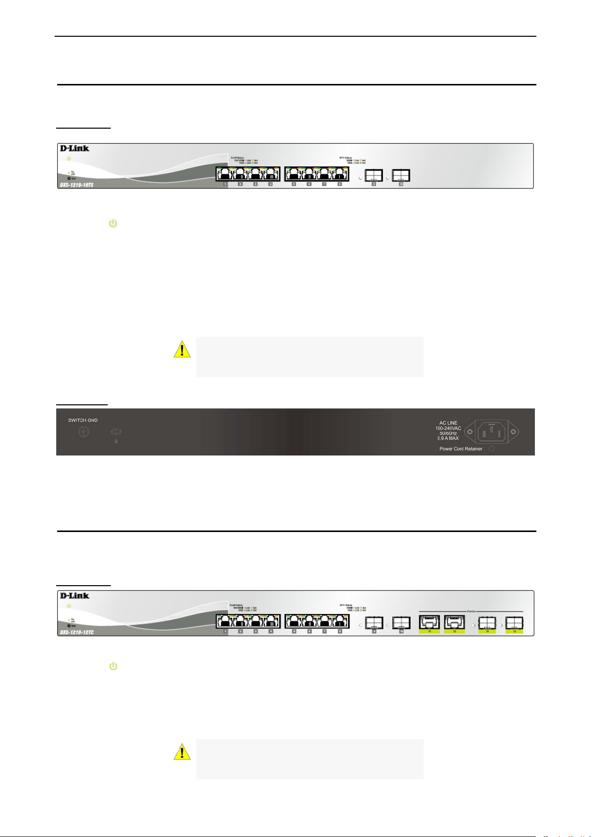
DXS-1210-10TS
8-Port 10GBASE-T and 2-Port SFP + Fiber port L2 10 Gigabit Ethernet Switch.
Front Panel
Figure 1.1 – DXS-1210-10TS Front Panel
Power LED
Fan error: The Fan error LED lights up when the fan has runtime failure and is brought offline.
Reset: By pressing the Reset button, the Switch will change back to the default configuration and all
changes will be lost.
Port Link/Act/Speed LED (1-8, 9F, 10F): The port L EDs indicate a network link thr ough the co rresponding
port. Blinking indic ates the Switch i s either sending or receiving da ta to the port. When the port LED glows
amber, it indicates the port is running at 100M or 1000M. When the port LE D glows green, it is running at
10Gbps.
: The Power LED lights up when the Switch is connected to a power source.
CAUTION: The MiniGBIC ports should use UL
listed Optical Transceiver product, Rated Laser
Class I. 3.3Vdc
Rear Panel
Figure 1.2 – DXS-1210-10TS Rear Panel
Power: Connect the AC power cord to this port.
DXS-1210-12TC
8-port 10GBASE-T and 2-port 10G SFP+ al so wi th additional 2-port 10GBASE-T/SFP+ combo port L2 10
Gigabit Ethernet Switch.
Front Panel
Figure 1.3 – DXS-1210-12TC Front Panel
Power LED : The Power LED lights up when the Switch is connected to a power source.
Fan error: The Fan error LED lights up when the fan has runtime failure and is brought offline.
Port Link/Act/Speed LED (1-8, 9F, 10F, 11F, 12F): The Link/Act/Speed LED flashes, which indicates a
network link through the c orresponding por t. Blinking indic ates that the Switch is either sending or recei ving
data to the port. W hen a port has an amber light, this indicates that the port is running at 100M or 1000M.
When it has a green light it is running on 10Gbps.
CAUTION: The MiniGBIC ports should use UL
listed Optical Transceiver product, Rated Laser
Class I. 3.3Vdc.
33
Page 10
1 Product Introduction D-Link DXS-1210 Series User Manual
Reset: By pressing the Reset button, the Switch will change back to the default configuration and all
changes will be lost.
Rear Panel
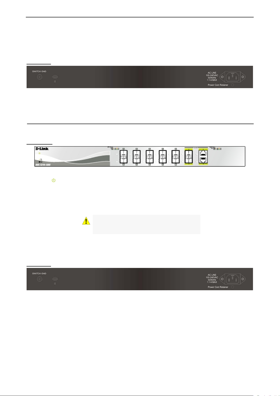
Figure 1.4 – DXS-1210-12TC Rear Panel
Power: Connect the AC power cord to this port.
DXS-1210-12SC
10-Port 10G SFP+ fiber port and 2-port 10GBASE-T/SFP + combo port L2 10 Gigabit Ethernet Switch.
Front Panel
Figure 1.5 – DXS-1210-12SC Front Panel
Power LED : The Power LED lights up when the Switch is connected to a power source.
Fan error: The Fan error LED lights up when the fan has runtime failure and is brought offline.
Port Link/Act/Speed LED (1-10, 11F, 12F): The Link/Act/Speed LED flashes, which indicates a network link
through the corresp onding port. Blinki ng indicates that the S witch is either sendi ng or receiving data t o the
port. When a port has an amber light, this indicates that the port is running on 100M or 1000M. When it has a
green light it is running on 10Gbps.
CAUTION: The MiniGBIC ports should use UL
listed Optical Transceiver product, Rated Laser
Class I. 3.3Vdc.
Reset: By pressing the Reset button, the Switch will change back to the default configuration and all
changes will be lost.
Rear Panel
Figure 1.6 – DXS-1210-12SC Rear Panel
Power: Connect the AC power cord to this port.
4
Page 11

2 Hardware Installation D-Link DXS-1210 Series User Manual
2 Hardware Installation
This chapter provides unpacking and installation information for the D-Link DXS-1210 Series Switch.
Safety Cautions
To reduce the risk of bodily i njury, elec trical s hock, fi re,and d amage to the equi pment, o bserve t he foll owing
precautions:
• Observe and follow service markings.
• Do not service any product except as explained in your system documentation.
• Opening or removing covers that are marked with the triangular symbol with a lightning bolt may
expose you to electrical shock.
• Only a trained service technician should service components inside these compartments.
• If any of the foll owing condi tions oc cur, unplug the pro duct from the electric al outlet an d replace t he part
or contact your trained service provider:
• The power cable, extension cable, or plug is damaged.
• An object has fallen into the product.
• The product has been exposed to water.
• The product has been dropped or damaged.
• The product does not operate correctly when you follow the operating instructions.
• Keep your system away from radiators and heat sources. Also, do not block cooling vents.
• Do not spill food or liquids on your system components, and never operate the product in a wet
environment. If the system gets wet, contact your trained service provider.
• Do not push an y objects into the op enings of your s ystem. Doing so ca n cause fire or elec tric shock b y
shorting out interior components.
• Use the product only with approved equi p men t.
• Allow the product to cool before removing covers or touching internal components.
• Operate the produc t onl y from the type of external p ower so urce indic ated on the el ectrical ratings l abel.
If you are not sure of the type of power source required, consult your service provider or local reseller.
• Also, be sure that attached devices are electrically rated to operate with the power available in your
location.
• Use only approved power c able(s). If you have n ot be en provide d with a po wer cable fo r your s ystem or
for any AC powered optio n intende d for your s ystem, purc hase a po wer ca ble tha t i s approved f or use i n
your country. The po wer cabl e must be rat ed for the product and for the voltage and current marked on
the product’s electric al ratings label. The voltage and current rat ing of the cable shoul d be greater than
the ratings marked on the product.
• To help prevent electric shock, plug the system and peripheral power cables into properly grounded
electrical outlets.
• These cables are eq uipped with three-prong plugs to help ensure proper grounding. Do not
use adapter plugs or remo ve the grounding prong f rom a cable. If you must us e an extension
cable, use a 3-wire cable with properly grounded plugs.
• Observe extensi on cable and power st rip ratings. M ake sure that the to tal ampere rating of al l
products plugged into th e extension cable or power strip does not exce ed 80 percent of the
ampere ratings limit for the extension cable or power strip.
• To help protect your system from sudden, transient increases and decreases in electrical
power, use a surge suppressor, line conditioner, or uninterruptible power supply (UPS).
• Position system cables and power cables carefully; route cables so that they cannot be
stepped on or tripped over. Be sure that nothing rests on any cables.
• Do not modify power cables or plugs. Consult a licensed electrician or your power company for
site modifications.
• Always follow your local/national wiring rules.
• When connecting or disc onnecti ng power to hot -plugg able powe r suppl ies, if off ered with your
system, observe the following guidelines:
55
Page 12
2 Hardware Installation D-Link DXS-1210 Series User Manual
• Install the power supply before connecting the power cable to the power supply.
• Unplug the power cable before removing the power supply.
• If the system has multiple sources of power, disconnect power from the system by
unplugging all power cables from the power supplies.
• Move products with care; ensure that all casters and/or stabilizers are firml y connected to the s ystem.
Avoid sudden stops and uneven surfaces.
Step 1: Unpacking
Open the shipping carton and carefully unpack its contents. Please c onsult the packing list located in the
User Manual to make sure al l items a re present and undamag ed. If an y item is mis sing or dam aged, please
contact your local D-Link reseller for replacement.
One D-Link DXS-1210 Series switch
One Multilingual Getting Started Guide
User Guide CD with DNA (D-Link Network Assistant ) Prog ra m
Power Cord and Power Cor d Retai ne r
Rack-mount kit and Rubber Feet
If any item is found missing or damaged, please contact the local reseller for replacement.
Step 2: Switch Installation
For safe switch installation and operation, it is recommended that you:
Visually inspect the power cord to see that it is secured fully to the AC power connector.
Make sure that there is proper heat dissipation and adequate ventilation around the switch.
Do not place heavy objects on the switch.
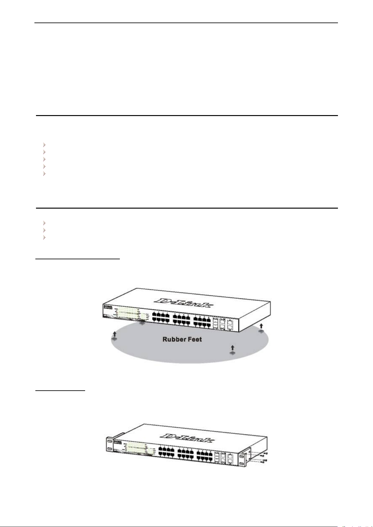
Desktop or Shelf Installation
When installing the s witch on a desktop or shelf, the rubber feet included wit h the device must be attac hed
on the bottom at each corn er of the device’s bas e. Allow enough ventilation s pace between the dev ice and
the objects around it.
Figure 2.1 – Attach the adhesive rubber pads to the bottom
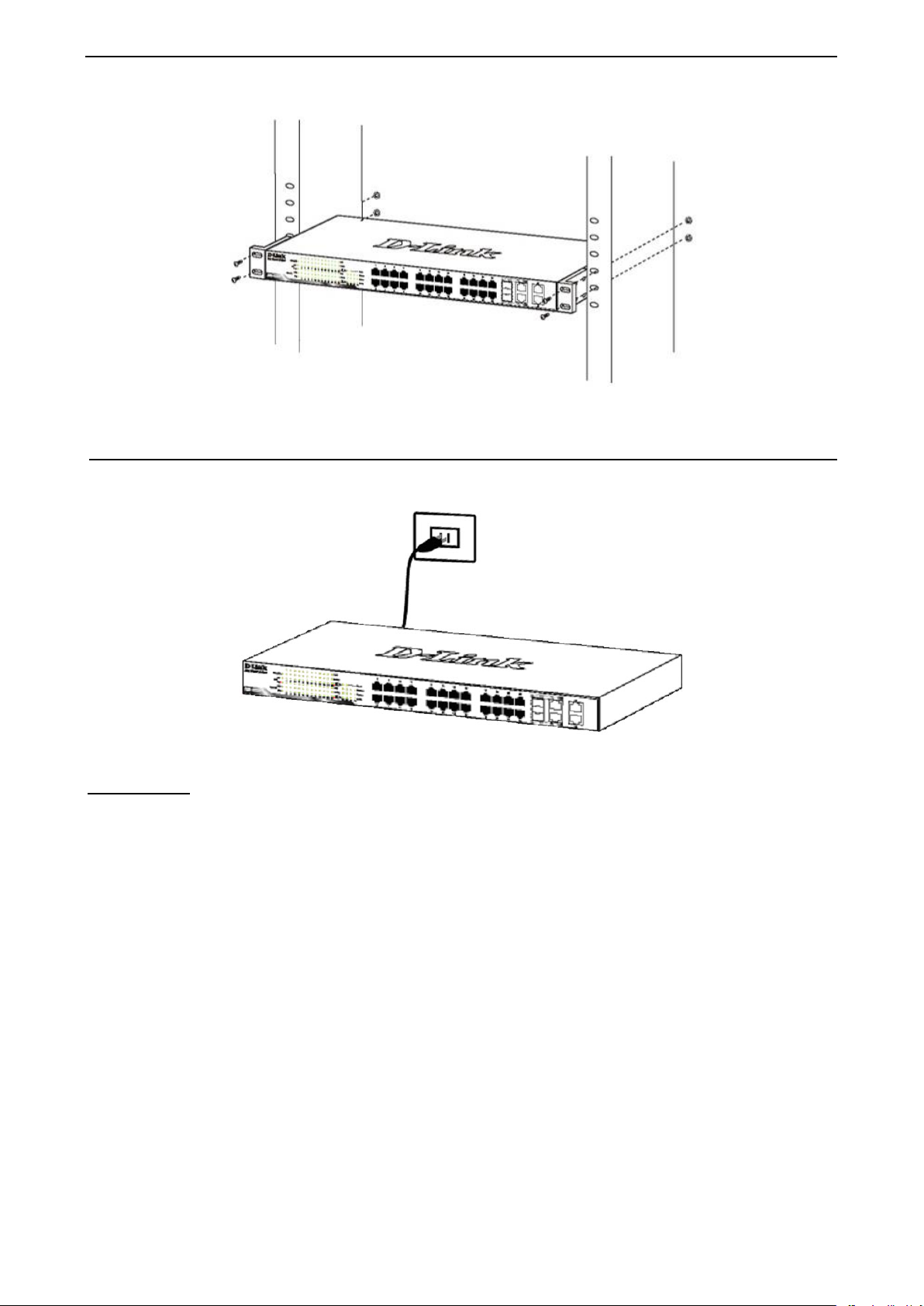
Rack Installation
The switch can be mounted in an E IA s t and ard s i z e 1 9-inc h r ac k, whic h c a n be p l ac ed i n a wi ring c l os et with
other equipment. To i nstall, attac h the mou nting br ackets to th e switc h’s si de panels (one on each si de) and
secure them with the screws provided (with 8 M3*6.0 size screws).
Figure 2.2 – Attach the mounting brackets to the Switch
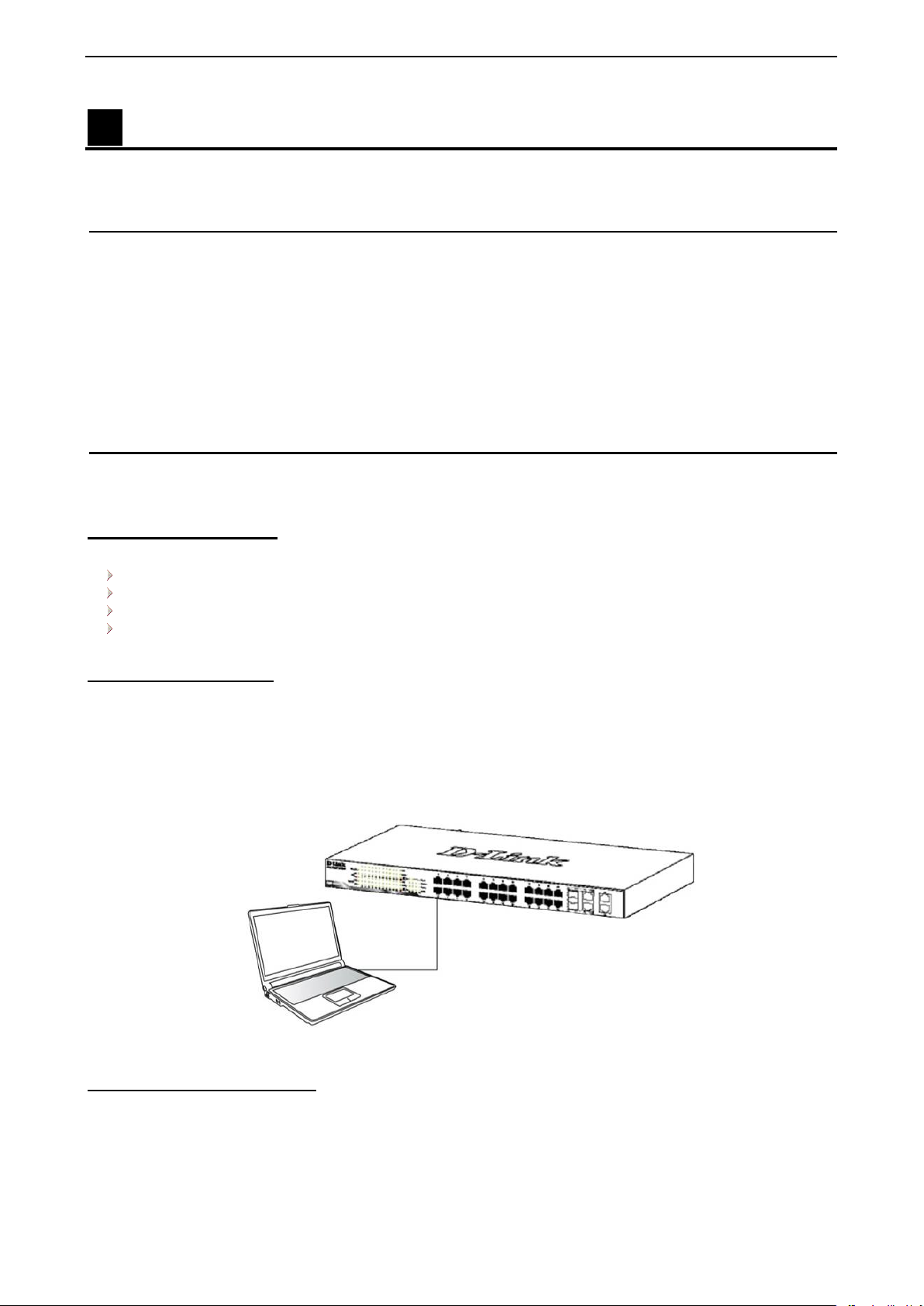
Then, use the screws provided with the equipment rack to mount the switch in the rack.
6
Page 13
2 Hardware Installation D-Link DXS-1210 Series User Manual
Figure 2.3 – Mount the Switch in the rack or chassis
Step 3 – Plugging in the AC Power Cord
The Switch can now be connected to the AC power. Connect the AC power cord to the rear of the switch and
to an electrical outlet (preferably one that is grounded and surge protected).
Figure 2.4 –Plugging the switch into an outlet
Power Failure
As a precaution, th e switch s hould be u nplugged in cas e of power f ailure. W hen po wer is resum ed, plug the
switch back in.
77
Page 14
3 Getting Started D-Link DXS-1210 Series User Manual
3 Getting Started
This chapter introduces the management interface of D-Link DXS-1210 Series Switch.
Management Options
The D-Link DXS-1210 Series. Switch can be managed through any port by using the Web-based
Management, or through any PC using CLI commands.
Each switch must b e assigned its own IP Address , which is used for communic ation with the Web-Based
Management or a SNMP network man ager. The PC s hould have an IP address in the sa me subnet as t he
switch. Each switch can allow up to four users to access the Web-Based Management concurrently.
Please refer to the following installation instructions for the Web-based Management.
Using Web-based Management
After a successful ph ysic al i ns tal l ati on, you can c on fi gure the S witch, monit o r the network status, and dis play
statistics using a web browser.
Supported Web Browsers
The embedded Web-based Management currently supports the following web browsers:
Internet Explorer 8 or later version
Chrome
Firefox
Safari
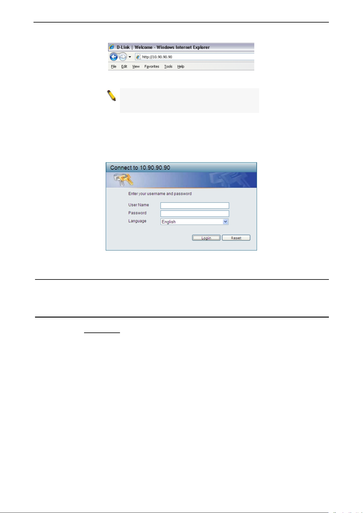
Connecting to the Switch
You will need the following equipment to begin the web configuration of your device:
1. A PC with a RJ-45 Ethernet connection
2. A standard Ethernet cable
Connect the Ethernet cable to any of the ports on the front panel of the switch and to the Ethernet port on the
PC.
Figure 3.1 – Connected Ethernet cable
Login Web-based Management
In order to login and config ure the s witch vi a Web-based GUI, th e PC must have an IP address in the same
subnet as the s witch. Fo r example, if the s witc h h as a n IP add ress of 10.90.90.90, the PC should have an IP
address of 10.x.y.z (where x/y is a num ber between 0 ~ 254 and z is a number between 1 ~ 254), and a
subnet mask of 255.0.0.0. There are two ways to launch the Web-based Management.
8
Page 15
3 Getting Started D-Link DXS-1210 Series User Manual
Figure 3.2 –Enter the IP address 10.90.90.90 in the web browser
NOTE: The s witch's fac tor y default IP addres s is
10.90.90.90 with a subne t mask of 255.0.0 .0 and
a default gateway of 0.0.0.0.
When the following login dialog box appears, enter the password and choose the language of the Webbased Management interface then click OK.
The switch supports 10 languages including English, Traditional Chinese, Simplified Chinese, German,
Spanish, French, Italian, Portuguese, Japanes e and Russian. By defa ult, the Username and P assword are
empty and the language is English.
Figure 3.3 – Login Dialog Box
Smart Wizard
After a successful logi n, the Smart Wizard will guide you through essential settings of the D-Link DXS-1210
Series Switc h. Pl eas e refer to the Smart Wizard Configuration section for details.
Web-based Management
By clicking the Exit button i n the Smart W i zard, you will enter the Web-based Management interface. Pleas e
refer to Chapter 4 Configuration
for detailed instructions.
99
Page 16
4 Configuration D-Link DXS-1210 Series User Manual
The IPv4 Information of Smart Wizard
4 Configuration
The features and functions of the D-Link DXS-1210 Series Switch can be configured for optimum use
through the Web-based Management Utili t y.
Smart Wizard Configuration
After a successful logi n, the Smart Wizard will guide you through essent ial settings of the D-Link DXS-1210
Series Switch. If you do not plan to change anything, click Exit to leave the Wizard and enter the Web
Interface. Yo u can also skip it by clicking Ignore the wizard next time for the next time you logon to th e
Web-based Management.
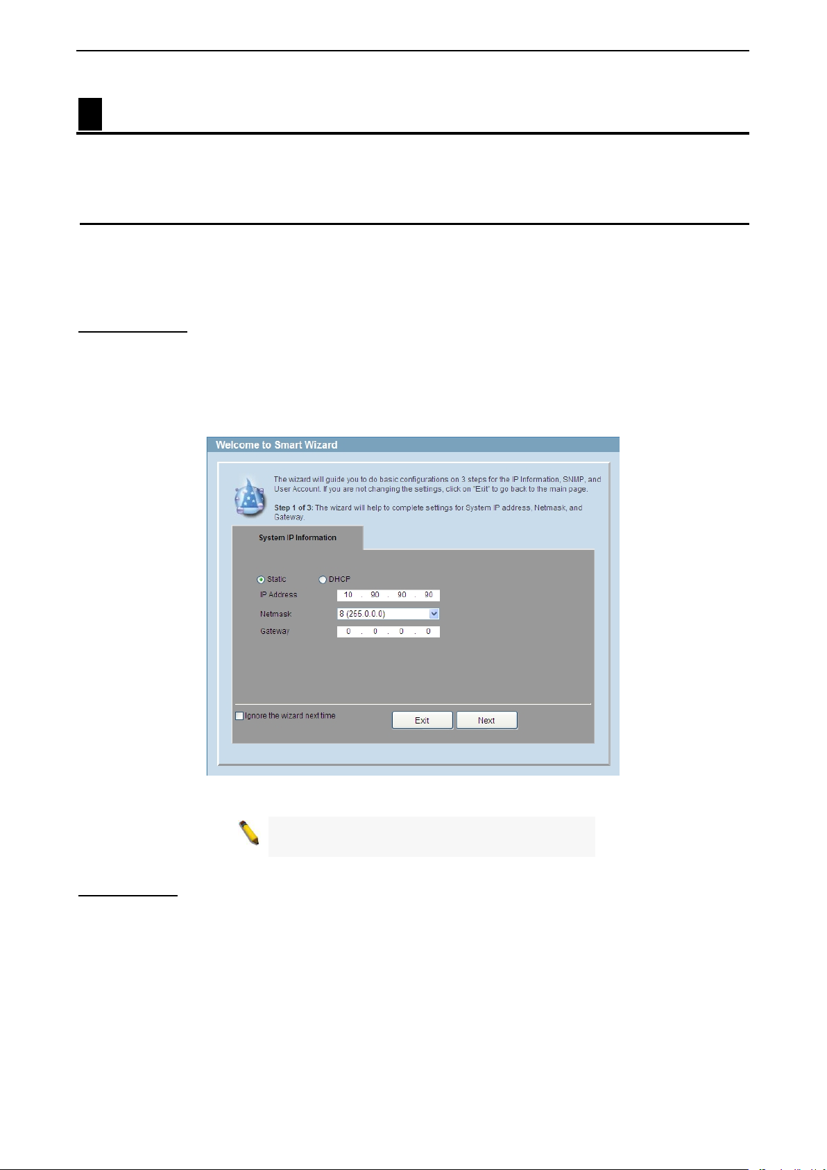
IPv4 Information
IPv4 Information will guide you to do basic configurations on 3 steps for the IP Information, access password,
and SNMP. Select Static, to manuall y enter a new IP Address, Netmask and Gateway address, o r select
DHCP to automatic ally receive IP settings from a DHCP se rver. Click the NEXT button to e nter the SNMP
settings page The I P addr e s s is all o wed for IPv4 and IPv 6 add ress . If you are not changing the settings, click
Exit button to go b ack to the main page. Or you can cli ck on Ignore the wizard next time to skip wizard
setting when the switch boots up.
Figure 4.1 – IPv4 Information in Smart Wizard
NOTE:
does not support IPv6 address.
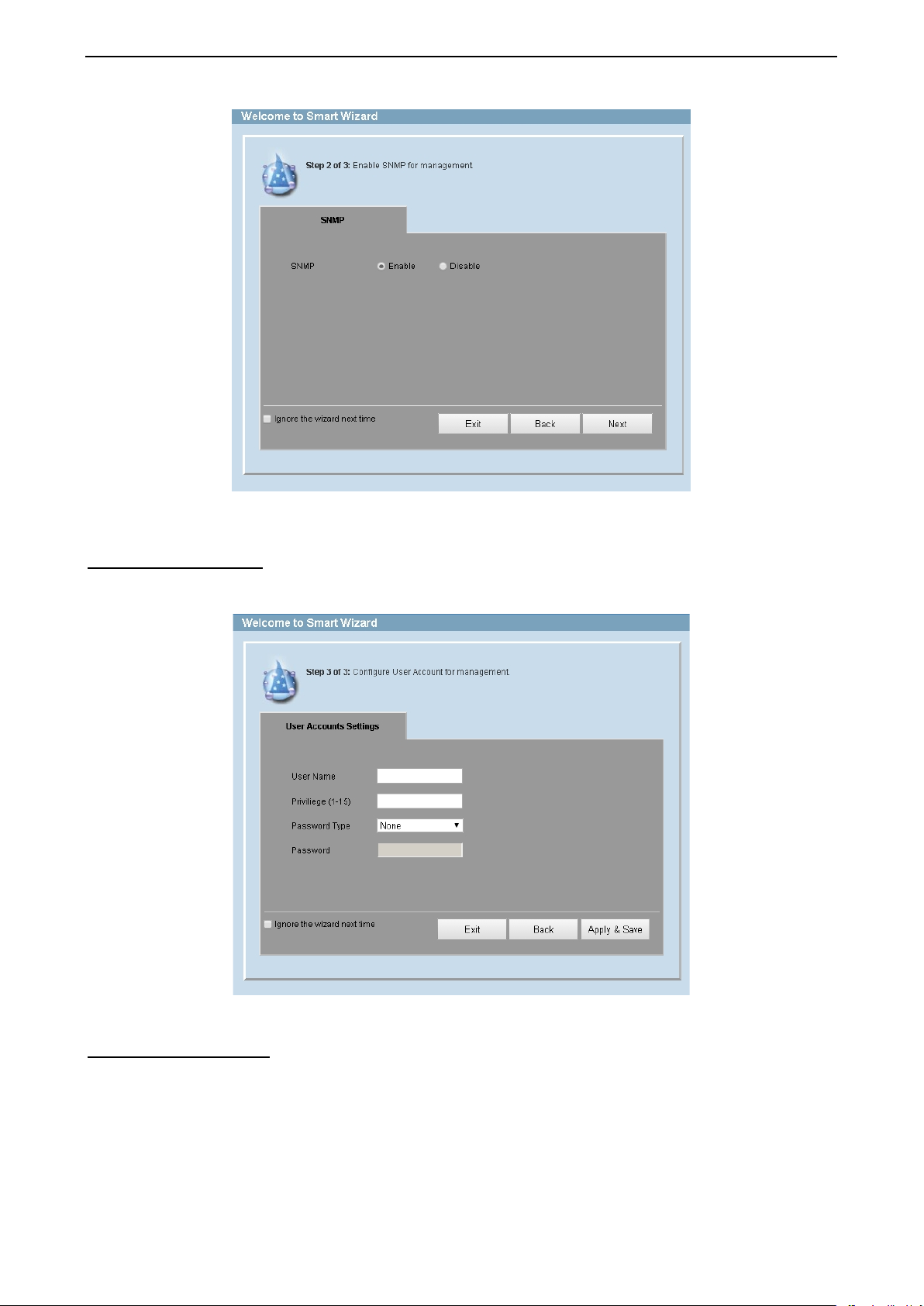
SNMP Settings
The SNMP Settings page allows you to quickly enable/disable the SNMP function. The default SNMP Setting
is Disabled. Click Enabled and then click Next, then it will enter the User Accounts Settings page.
10
Page 17
4 Configuration D-Link DXS-1210 Series User Manual
Figure 4.2 – SNMP Settings in Smart Wizard
User Accounts Settings The Use r Accounts Settings page allows you to quic kly specify the user account function. Enter the User
Name, Privilege, Password Type and Password. Click Apply & Save to save the configuration.
Figure 4.3 – User Accounts Setting in Smart Wiza rd
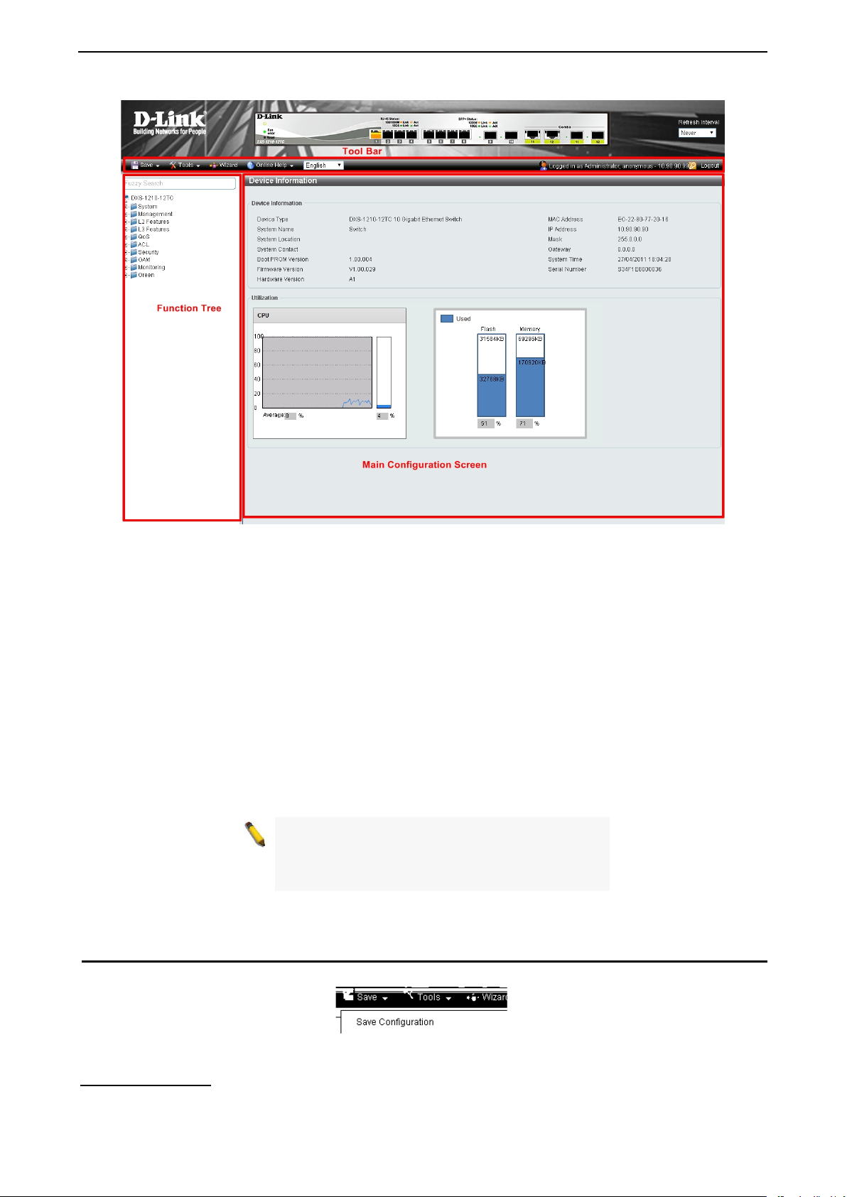
Web-based Management After clicking the Exit button in the Smart Wizard you will see the screen below:
1111
Page 18
4 Configuration D-Link DXS-1210 Series User Manual
If you close the web browser without
Figure 4.4 – Web-based Management
The above image is the Web-based Man agemen t screen. The th ree main areas are the Tool Bar on to p, the
Function Tree, and the Main Configuration Screen.
The Tool Bar provides a quick and convenient way for essential utility functions like firmware and
configuration manageme nt.
By choosing different functions in the Function Tree, you can change all the settings in the Main
Configuration Screen. The main configuration s cre e n wil l s ho w the c urr ent s tat us of you r S witch by clicking
the model name on top of the function tree.
At the upper right corner of the screen the username and current IP add ress will be displayed.
Under the username is the Logout button. Click this to end this session.
NOTE:
clicking the Logout butto n fi rst, th en it will be seen
as an abnormal e xit and the logi n session will still
be occupied.
Click the D-Link logo at the upper-left corner of the screen to be redirected to the local D-Link website.
Tool Bar > Save Menu
The Save Menu provides Save Configuration and Save Log functions.
Figure 4.5 – Save Menu
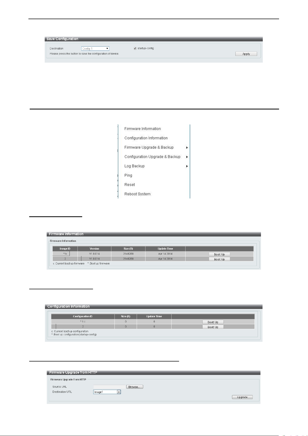
Save Configuration
Select Save configuration to save the configuration changes to the Switch’s non-volatile RAM.
12
Page 19
4 Configuration D-Link DXS-1210 Series User Manual
Figure 4.6 – Save Configuration
Destination: Select the destination to save the configuration to.
Startup-config: Check the box to enable the startup configuration function.
Click the Apply button to save your settings.
Tool Bar > Tool Menu
The Tool Menu offers global function controls such as Reset, Reboot Device, Configuration Backup and
Restore, Firmware Backup and Upgrade.
Figure 4.7 – Tool Menu
Firmware Information
Display the firmware for the 2 firmware i mag es , inc l udi ng the i m age that has be en boote d and the image that
is selected for the next reboot.
Figure 4.8 – Tool Menu > Firmware Information
Configuration Information
Display information for the Switch configuration. This includes the configuration that has been loaded and the
configuration that is selected for the next reboot.
Figure 4.9 – Tool Menu > Configuration Information
Firmware Upgrade & Backup > Firmware Upgrade from HTTP Allow existing firmware file to be uploaded to the Switch from HTTP.
1133
Page 20

4 Configuration D-Link DXS-1210 Series User Manual
Switch will reboot after
restoring the firmware, and all current
Switch will reboot after
and all current configurations
Figure 4.10 – Tool Menu > Firmware Upgrade & Ba ckup > Firmware Upgrade from HTTP
Note: The
configuration will be lost.
Firmware Upgrade & Backup > Firmware Upgrade from TFTP
Upgrade firmware b y using TFTP. Ente r the TFTP IP address, source URL, and s elect a Destination URL.
Click Upgrade.
Figure 4.11 – Tool Menu > Firmware Upgrade & Backup > Firmware Upgrade from TFTP
Note: The
restoring,
will be lost
Firmware Backup to HTTP & Backup > Firmware Backup to HTTP To save a backup of the firmware, select the source URL and then click Backup.
Figure 4.12 – Tool Menu > Firmware Upgrade & Ba ckup > Firmware Backup to HTTP
Firmware Backup to HTTP & Backup > Firmware Backup to TFTP
To save a backup of the firmware us ing TFTP, ente r the TFTP server IP address, the source URL, and the
destination URL. Click Backup.
Figure 4.13 – Tool Menu > Firmware Upgrade & Ba ckup > Firmware Backup to TFTP
Configuration Upgrade & Backup > Configurati o n Restore from HTTP
To restore the S witch from a save d configuration fil e, select a Source URL , configuration Destination and
click Restore.
Figure 4.14 – Tool Menu > Configurat ion Upgrade & Backu p > Configuration Restore from HTTP
Startup-config: Check the box to enable the startup configuration function.
Configuration Upgrade & Backup > Configuration Restore from TFTP
To load the Switch’s configuration from a saved configuration file using TFTP, enter the TFTP server IP
address and source URL, then click Restore.
14
Page 21
4 Configuration D-Link DXS-1210 Series User Manual
Figure 4.15 – Tool Menu > Configuration Upgrade & Backup > Configuration Restore from TFTP
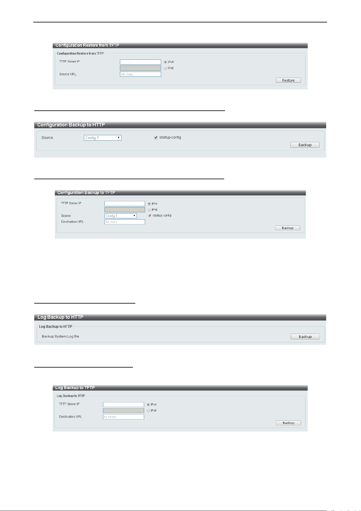
Configuration Upgrade & Backup > Configurati o n Backup to HTTP To save the current configuration to a file, click Backup.
Figure 4.16 – Tool Menu > Configuration Upgrade & Backup > Configuration Backup to HTTP
Configuration Upgrade & Backup > Configuration Backup to TFTP To save the current configuration to a file using TFTP, click Backup.
Figure 4.17 – Tool Menu > Configuration Upgrade & Backup > Configuration Backup to TFTP
TFTP Server IP: Select IPv4 or IPv6 and enter the IP address.
Source: Select the source configuration file.
Startup-config: when chec king the box, only the current s tartup configuration file will be backed up which
may be stored in the “Config 1” or “Config 2” location.
Destination URL: Enter the destination URL for the backup.
Log Backup > Log Backup to HTTP To save the log to a file and click Backup.
Figure 4.18 – Tool Menu > Log Backup > Log Backup to HTTP
Log Backup >Log Backup to TFTP
To save the log to a file using TFTP, enter the TFPT server IP address and destination URL then click
Backup.
Figure 4.19 – Tool Menu > Log Backup > Log Backup to TFTP
TFTP Server IP: Select IPv4 or IPv6 and enter the IP address.
Destination URL: Enter the destination URL for the backup.
1155
Page 22

4 Configuration D-Link DXS-1210 Series User Manual
Ping
To ping a computer or devic e, enter either Target IPv4 or IPv 6 Address, Ping T imes and Timeout. Enter
the required info rmation, Tick the Infinite option, to disable the Ping Times feature and click Apply. The
results will be displayed in the Result box.
Figure 4.20 – Ping
Reset Select which reset option you want to perform and cl i ck Apply.
Figure 4.21 – Tool Menu > Reset
Reboot System Select to save your current settings and then click Reboot to restart the Switch.
Figure 4.22 – Tool Menu > Reboot System
Destination: Select the configuration destination to be saved.
Startup-config: When checki ng the box, only the current startup confi guration file will be bac ked up which
may be stored in the “Config 1” or “Config 2” location.
Tool Bar > Smart Wizard
By clicking the Smart Wizard button, you can re-run to the Smart Wizard if yo u wish to make any changes.
Tool Bar > Online Help
The Online Help provides two ways of online support: D-link Support Site will lead you to the D-Link
website where you can fi nd onl ine resources such as updated firm ware; User Guide c an offer an immediate
reference for the feature definition or configuration guide.
Figure 4.23 – Online Help
16
Page 23
4 Configuration D-Link DXS-1210 Series User Manual
Figure 4.24 – User Guide Micro Site
1177
Page 24
4 Configuration D-Link DXS-1210 Series User Manual
Function Tree
All configuration op tions on the switch are acces sed through the Setup menu on the left s ide of the main
window. Click on the set up item that you want to configure. The following sec tions provide more detailed
description of each feature and function.
Figure 4.25 –Function Tree
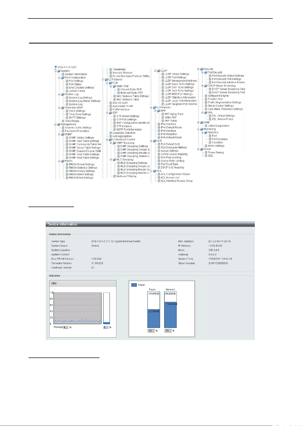
Device Information
The Device Informat ion pro vides an overvie w of the s witch, incl uding essen tial infor mation s uch as fi rmware
& hardware information, and IP settings.
Figure 4.26 – Device Information
System > System Information
The System Setting page allows you to configure basic system information.
System Information Settings: Enter a System Name, System Location and System Contact.
18
Page 25
4 Configuration D-Link DXS-1210 Series User Manual
Figure 4.27 – System > System Information
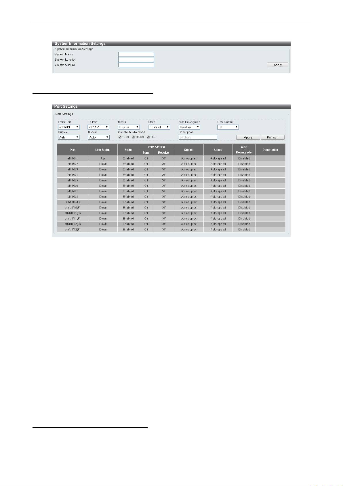
System > Port Configuration > Port Settings In the Port Settings page, the status of all ports can be monitored and adjusted for optimum configuration.
Figure 4.28 – System > Port Configuration > Port Settings
From Port / To Port: Select the appropriate port range to be configured.
State: Enable or disable the physical port.
Auto Downgrade: To enable or disable automatically downgrading the advertised speed in case a link
cannot be established at the available speed.
Flow Control: Select On or Off. Ports c onfigured for full-duplex use 802.3x flo w control, half-duplex ports
use back-pressure flow control, and Auto ports use an automatic selection of the two.
Duplex: Select the duplex mode used. Options to choose from are Auto and Full.
Speed: Select the speed for the ports. The spe ed values are Auto, 100M, 1000M, 1000M M aster, 1000M
Slave, and 10G. The Switch allo ws you to configure two t ypes of Gigabit conne ctions; 1000M M aster and
1000M Slave whic h refer to connections runni ng a 1000BASE-T cable for co nnection between the Switch
port and another devi ce capable of a Gigabi t connection. The master setting (1000M Maste r) will allow the
port to advertise c apabilities related to duple x, speed and physical l ayer type. The master setti ng will also
determine the master and slav e relationship bet ween the two con nected ph ysical layers. T his relations hip is
necessary for establi shing the timing cont rol between t he two physical l ayers. The timing c ontrol is set on a
master physical layer b y a local source. The sl ave setting (10 00M Slave) uses loop timing, wher e the timing
comes from a data stream recei ved from the master. If one connection is set for 1000M Master, the other
side of the connecti on must be se t for 1000M Slave. An y other configu ration will resul t in a link down statu s
for both ports.
Capability Advertised: When the Speed is set to Auto, these capabilities are advertised during autonegotiation.
Description: Enter a 64 characters description for the corresponding port.
Click Apply button to save your settings.
Click the Refresh button to refresh the display table.
System > Port Configuration > Port Status
The Port Settings page allows you to view the Switch’s physical port status and settings. The table will
display the Port, Status, M A C Address , VLA N, Flow Control Operator, Duplex, Speed and T ype.
1199
Page 26

4 Configuration D-Link DXS-1210 Series User Manual
Figure 4.29 – System > Port Configuration > Port Status
System > Port Configuration > Error Disable Sett in g s
The E rror Disable Settings page allo ws you to configu re the sending of SN MP notificati ons for error disable
state.
Figure 4.30 – System > Port Configuration > Error Disable Settings
Error Disable Trap Settings:
Asserted: Select to enable or disable the notifications when entering into the error disabled state.
Cleared: Select to enable or dis abl e the notifi c ati ons wh en exiti ng fr om the erro r dis abl ed state.
Notification Rate (0-1000): Enter the number of traps per minute. The packets that exceed the rat e will be
dropped. The value is between 0 and 1000.
Click the Apply button to save your settings.
Error Disable Recovery Settings:
ErrDisable Cause: Specify the error di sable caus es. Optio ns to ch oose from are All, Port Security, Storm
Control, ARP Rate, BPDU Protect Protection, DHCP Rate and Loopback Detect.
State: Select to enable or disable the auto-recovery for an error port caused by the specified cause.
Interval (5-586400): Enter the time interval. The values are between 5 and 586400 seconds.
Click the Apply button to save your settings.
20
Page 27
4 Configuration D-Link DXS-1210 Series User Manual
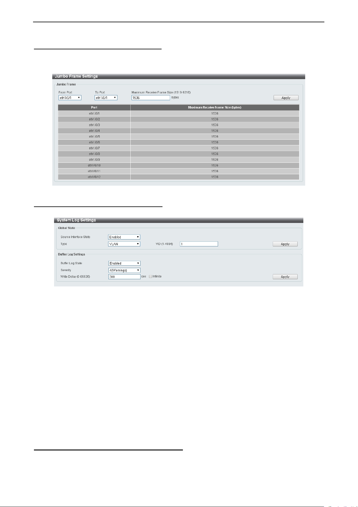
System > Port Configuration > Jumbo Frame
The Jumbo Frame page allows you to vie w and confi g ure t he J um bo Frame s ize and s etti ngs . J um bo f rames
are Ethernet frames with more than 1,518 bytes of payload. The Switch supports jumbo frames with a
maximum frame size of up to 9216 bytes.
System > System Log > System Log Settings
The System Log Settings p age al l o ws you to view and configure the system’s log settings.
Figure 4.31 –System > Port Configuration > Jumbo Frame
Figure 4.32 – System > System Log > System Log Settings
Global State:
Source Interface State: Select to enable or disable the source interface’s global state.
Type: Select the type of interface that will be used. The default option is VLAN.
VID (1-4094): Specifies the VLAN I D. The possible range is 1 – 4094,
Click the Apply button to save your settings.
Buffer Log Settings:
Buffer Log State: Select to en able or disable the buffer log state. Th e options are Enable, Disable and
Default.
Severity: Select the severity value of the type of information that will be logged. The values are 0
(Emergencies), 1 (Alerts), 2 (Critical), 3 (Errors), 4 (Warnings), 5 (Notifications), 6 (Informational), and 7
(Debugging).
Write Delay (0-65535): Enter the i nterval for periodic writing of the logging buffer to Flash. The value is
between 0 and 65535 sec o nds . An d def aul t is 300 s econds. Tick the Infinite op t ion, to dis abl e th e writ e del ay
feature.
Click the Apply button to save your settings.
System > System Log > System Log Server Settings
The System Log Server Settings page allows you to view and configure the system log’s server settings.
2211
Page 28

4 Configuration D-Link DXS-1210 Series User Manual
Figure 4.33 – System > System Log > System Log Server Settings
IP Address: Select and enter the IPv4 address or IPv6 Address.
UDP Port (514 or 1024-65535): Enter the s ystem lo g s erver’ s UDP port nu mber. T his v alue must be 51 4 o r
between 1024 and 65535. The default value is 514.
Severity: Select the severi ty value of th e type of i nformation t hat will be logged. Options to choose f rom are
0 (Emergencies), 1 (Alerts), 2 (Critical), 3 (Er rors), 4 (Warnings), 5 (Notifications), 6 (Informational),
and 7 (Debugging).
Facility: Select the facility value. The values must be between 0 and 23.
Click the Apply button to save your settings.
System > System Log > System Log
The System Log page displays the system logs on the Switch.
Figure 4.34 – System > System Log > System Log
System > Time and SNTP > Clock Settings
The Clock Settings page allows you to configure the time settings for the Switch.
Figure 4.35 – System > Time and SNTP > Clock Settings
Time (HH:MM:SS): Enter the current time in hours, minutes, and seconds.
Data (DD/MM/YYYY): Enter th e current day, month, and year to update the system clock.
Click the Apply button to save your settings.
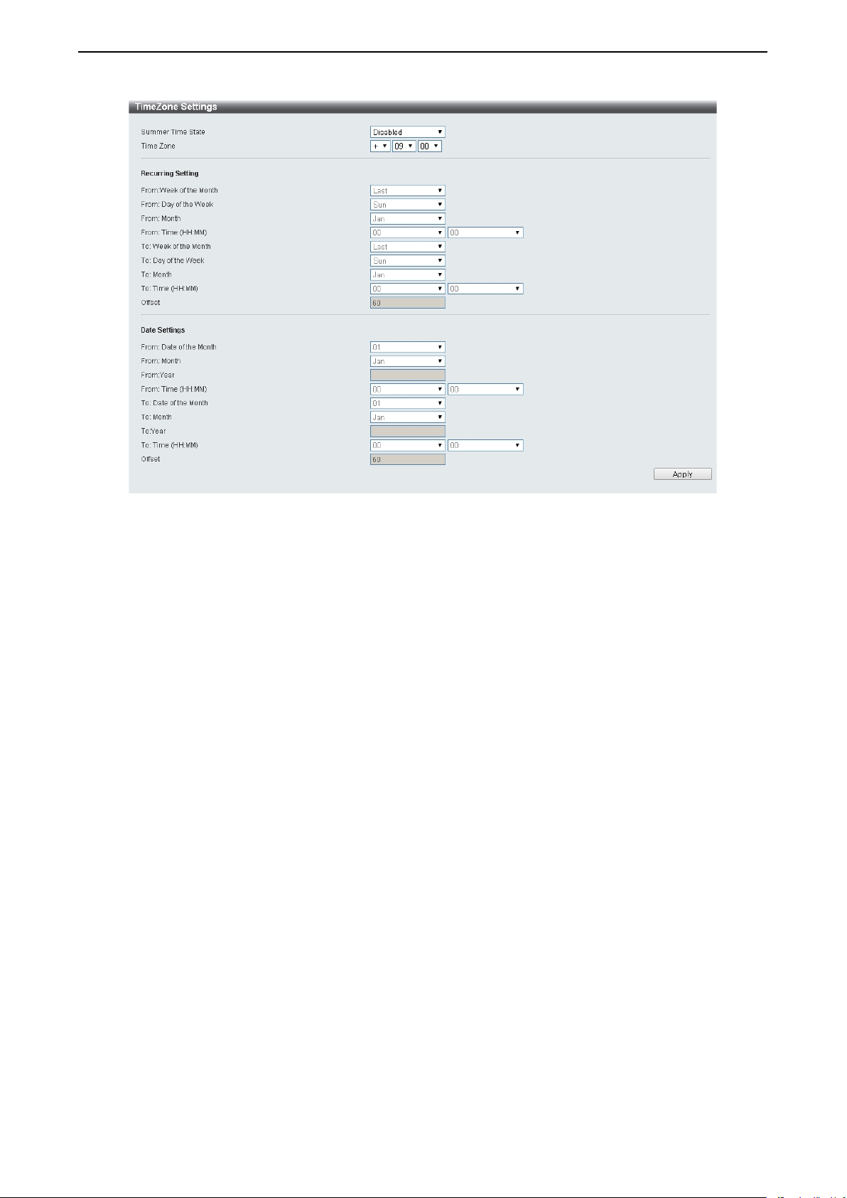
System > Time and SNTP > Time Zone Settings
The Time Zone Settings page allows you to configure time zones and Daylight Saving Time settings for
SNTP.
22
Page 29
4 Configuration D-Link DXS-1210 Series User Manual
Figure 4.36 – System > Time and SNTP > Time Zone Settings
Summer Time Stat e: Select Summer Time State setting. Opti ons t o choos e f ro m are Disabled, Recurring
Setting, and Date Setting.
Time Zone Offset: Select the local time zone’s offset from Coordinated Universal Time (UTC).
The Recurring Setting can be configured below:
From:Week of the Month – Select week of the month that daylight saving time will start.
From:Day of the Week - Select day of the week that daylight saving time will start.
From:Month – Select the month that daylight time will start.
From:Time in HH MM – Select the time of the day that daylight saving time will start.
To:Week of the Month – Select week of the month that daylight saving time will end.
To:Day of the Week – Spec ify day of the week that daylight saving time will end.
To:Month – Select the month that daylight saving time will end.
To:Time In HH MM – Select the time of the day that daylight saving time will end.
Offset – Enter the numbe r of minutes to ad d during daylight saving time. The de fault val ue is 60. The range
of this offset is 30, 60, 90 and 120.
The Date Setting can be configured below:
From:Date of the Month – Select date of the month that daylight saving time will start.
From:Month – Select the month that daylight saving time will start.
From:Year – Select the year that the daylight saving time will start.
From:Time In HH MM – Select the time of the day that daylight saving time will start.
To:Date of the Month – Select the date of the month that daylight saving time will end.
To:Month – Select the month that daylight saving time will end.
To:Year – Select the year that the daylight saving time will end.
To:Time In HH MM – Select the time of the day that daylight time will end.
Offset – Select the number of minutes to add du ring daylight saving
of this offset is 30, 60, 90 and 120.
Click the Apply button to save your settings.
time. The d e faul t val ue i s 60. The ran ge
2233
Page 30
4 Configuration D-Link DXS-1210 Series User Manual
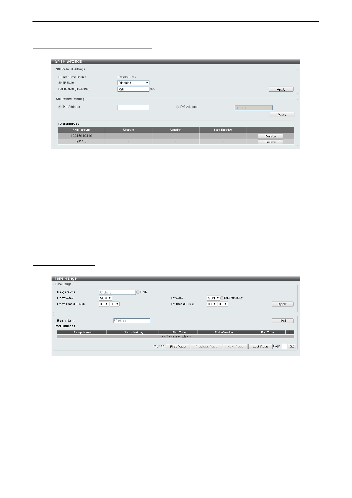
System > Time and SNTP > SNTP Settings
The SNTP Settings page allows you to configure the time settings for the Switch.
Figure 4.37 – System > Time and SNTP > SNTP Settings
SNTP Global Settings:
SNTP State: Select to enable or disable the SNTP state.
Poll Interval (30-99999): Enter the poll i nterval. T he value i s from 30 t o 99 999 sec onds. Th e def ault inte rva l
is 720 seconds.
Click the Apply button to save your settings.
SNTP Server Setting:
IPv4 Address: Enter the IPv4 address of the SNTP server which provides the clock synchronization.
IPv6 Address: Enter the IPv6 address of the SNTP server which provides the clock synchronization.
Click the Apply button to add the SNTP server.
System > Time Range
The Time Range page al lows you to view and configure the time range settings for the Switch.
Figure 4.38 – System > Time Range
Range Name: Enter a name for the time range. The name can be up to 32 characters long.
From Week / To W eek: Select the starting and ending days of the week that will be used for this time range.
Tick the Daily option to us e t his ti me ran ge fo r every day of the we ek. T i ck th e End Week Day option t o use
this time range from the starting day of the week until the end of the week, which is Sunday.
From Time (HH:MM) / To Time (HH:MM): Select the starting and ending time of the day that will be used for
this time range. T he first drop-down menu selects the hour and the second drop-down menu selects the
minute.
Click the Apply button to save your settings.
Click the Find button to locate a specific entry based on the information entered.
24
Page 31

4 Configuration D-Link DXS-1210 Series User Manual
Management > User Accounts Settings
The User Accounts Settings page allows you to cre ate and configure user accounts. Active user account
sessions can be viewed. By default, there is no user account created on the Switch.
The pre-defined user account privilege levels supported by this switch are:
• Basic User – Privilege Level1. This user accoun t level has the lo west p riori ty of the user ac cou nts. T he
purpose of this type of user account level is for basic system checking.
• Operator – P rivi lege Level 12. Thi s user acc ount level is used to grant s ystem con figura tion info rmation
for users who need to ch ange or monitor s ystem configuration, except for security related info rmation
such as user accounts and SNMP account settings.
• Administrator – Privilege Level 15. This administrator user account level can monitor all system
information and change any of the system configuration settings expressed in this guide.
Figure 4.39 – Management > User Accounts Settings
User Name: Enter the name of the user name. The name can be up to 32 characters long.
Privilege (1-15): Select the privilege level for this account. The value is between 1 and 15.
Password Type: Select a password type for this user account. The options are None, Plain Text, and
Encrypted.
Password: If you selected either Pl ain Text or Encrypted for the pas sword type, pleas e enter a password
for this user account.
Click the Apply button to save your settings.
Click the Delete button to remove the specified user account entry.
After clicking the S ession T ab le tab, the following page will appear:
Figure 4.40 – Management > User Accounts Sett ings – Session Table
Management > Password Encryption
The Password Encryption page allows you to enable or disable password encryption.
Figure 4.41 – Management > Password Encryption
Password Encryption State: Specify to enable or disable the password encryption.
Click the Apply button to save your settings.
2255
Page 32

4 Configuration D-Link DXS-1210 Series User Manual
Management > SNMP > SNMP Global Settings
Simple Network Management Protocol (SNMP) is an OSI Layer 7 (Application Layer) protocol designed
specifically for managi ng and monitoring network d evices. SNMP enables net work management stations to
read and modify the settings of gateways, routers, switches, and other network devices. Use SNMP to
configure system fea tures for proper operatio n, monitor performance and detect potential problems on the
Switch or your local network.
Managed devices that support SNMP incl ude software (referred t o as an agent), which runs locally on the
device. A defined set of va ri ables (m anaged object s) i s maintai ned by th e S NMP agen t and used t o man age
the device. These objec ts are defined in a Manage ment Informatio n Base (MIB), which p rovides a standar d
presentation of the infor mat i on cont rol l ed b y the on -b o ard S NMP ag ent. S NMP de fi nes bot h th e fo rmat of the
MIB specifications and the protocol used to access this information over the network.
The default SNMP glob al state is disabled. Select Enable and then select Trap Settings. Click Apply to
enable the SNMP function.
Figure 4.42 – Management > SNMP > SNMP Global Settings
SNMP Global Settings:
SNMP Global State: Select to enable or disable the SNMP feature.
SNMP Response Broadcast Request: Select
SNMP GetRequest packets.
SNMP UDP Port (0-65535): Enter the SNMP UDP port number. The value is between 0 and 65535.
Trap Source Interface: Specify the interface whose IP address will be used as the source address for
sending the SNMP trap packet.
Trap Settings:
Trap Global State: Select to enable or disable the sending of all or specific SNMP notifications.
SNMP Authentication Trap:
notifications. An authe nticationFailuret rap is generated when the device receiv es an SNMP message tha t is
not properly authenticated. The authentication method depends on the version of SNMP being used. For
SNMPv1 or SNMPv2c, authentication failure occurs if packets are formed with an incorrect community string.
For SNMPv3, authentic ation failure occurs if pac kets are formed with an i ncorrect SHA/MD5 authentication
key.
Port Link Up: Tick this option to control the port link up notifications.
Port Link Down: Tick this option to control the port link down notifications.
Coldstart: Tick this option to control the sending of SNMP coldStart notifications.
Warmstart: Tick this option to control the sending of SNMP warmStart notifications.
Click the Apply button to save your settings.
Tick this option to control the sending of SNMP authentication failure
to enable or disable the server to response to broadcast
26
Page 33

4 Configuration D-Link DXS-1210 Series User Manual
Management > SNMP > SNMP View Table Settings
The SNMP View page allows you to m aintain SNMP views to communit y strings that defin e the MIB objects
which can be accessed by a remote SNMP manager.
Figure 4.43 – Management > SNMP > SNMP View Table Settings
View Name: Create a name of the view, up to 32 characters.
Subtree OID: The Object Identifier (OID) Subtree for the vi ew. The OID identifi es an object tree (MIB tree)
that will be included or excluded from access by an SNMP manager.
View Type: Select the OIDs that can accessed by a SNMP manager.
Click Add to create a new view or Delete to remove an existing view.
Management > SNMP > SNMP Community Table Settings
The SNMP Communit y pa ge allows you to set the S NMP community string of the switch. SNMP man agers
using the same community string are permitted to gain access to the Switch's SNMP agent.
Figure 4.44 – Management > SNMP > SNMP Community Table Settings
Key Type: Select the key type for the SNMP community. Select either Plain Text or Encrypted.
Community Name: Select an al phanum eri c string of up to 3 2 charac ters that i s used to i denti fy memb ers of
an SNMP community. This string is used like a password to give remot e SNMP managers access to MIB
objects in the Switch’s SNMP agent.
View Name: Enter an alphanu meric string of up to 32 cha racters that is use d to identify the group of MIB
objects that a remot e SNMP manage r is allowed to a ccess on the S witch. The vie w name must exist i n the
SNMP View Table.
Access Right: Select the user’s access rights from the drop-down menu:
Read Only - SNMP community members using the community string created can only read the
contents of the MIBs on the Switch.
Read Write - SNMP community members us ing the community string creat ed can read from, and
write to the contents of the MIBs on the Switch.
IP Access-List Name: Enter the name of the s tandard ac cess l ist to cont rol the user to us e this c ommunit y
2277
Page 34

4 Configuration D-Link DXS-1210 Series User Manual
string to access to the SNMP agent.
Click Add to a new entry based on the information entered or Delete to re mov e the specified entry.
Management > SNMP > SNMP Group Table Settings
The SNMP Group page all ows you to ass ign SNMP Users into S NMP Groups . SNMPv3 can c ontrol access
and security policies on a per group basis.
Figure 4.45 – Management > SNMP > SNMP Group Table Settings
Group Name: Enter the SNMP user group of up to 32 characters.
User-based Security Model: Select the SNMP security model.
SNMPv1 - SNMPv1 does not support any security features.
SNMPv2c - SNMPv2 supports both c entralized and distributed network m anagement strategies. It
includes improvemen ts in the Structure of Manageme nt Information (SMI) and adds some s ecurity
features.
SNMPv3 - SNMPv3 p rovides secur e access to devices thr ough a combi nation of authentic ation and
encrypting packets over the network.
Security Level: This function is only available when you select SNMPv3 security level.
NoAuthNoPriv - No author i zation a nd no encryption for packets sent between the Switch and S NMP
manager.
AuthNoPriv - Authorizatio n is required, but no encr yption for packets sent between th e Switch and
SNMP manager.
AuthPriv – Both au thorization and encryption are required fo r packets s ent between the Switch and
SNMP manger.
IP Address-List Name:
Read View Name: Enter a SNMP group name for users that are allowed SNMP read privileges to the
Switch's SNMP agent.
Write View Name: Enter a SNMP group name for users that are allowed SNMP write privileges to the
Switch's SNMP agent.
Notify View Name: Enter a SNMP group name for users th at can recei ve SNMP trap messages ge nerated
by the Switch's SNMP agent.
Click the Add button to add a new entry based on the information entered.
Click the Delete button to remove the specified entry.
Management > SNMP > SNMP Engine ID Local Settings
The Engine ID is a unique identifier used to identify the SNMPv3 engi ne on the Sw itc h.
Input the Engine ID then c lick Apply to appl y the changes or click Default to change back to the default
value.
28
Page 35

4 Configuration D-Link DXS-1210 Series User Manual
Figure 4.46 – Management > SNMP > SNMP Engine ID Local Settings
Management > SNMP > SNMP User Table Settings
The SNMP User Table Settings page allows you to maintain the SNMP user table fo r the use of SNMPv3.
SNMPv3 allows o r restricts users us ing the MIB O ID, and encrypts t he SNMP messages sent out bet ween
users and Switch.
Figure 4.47 – Management > SNMP > SNMP User Table Settings
User Name: Enter a SNMP user name of up to 32 characters.
Group Name: Enter the SNMP group of the SNMP user.
SNMP Version: Select the SNMP version of the user. The options to choose are v1, v2c and v3.
SNMP V3 Encryption: When selecting v3 in the SNMP Version drop-down list, this option is available.
Options to choose from are None, Password, and Key.
Auth-Protocol by Password: Select either MD5 or SHA to be the authentication protocol. Enter a password
for SNMPv3 encryption in the right column.
MD5 – Select t o use the HMAC-MD5-96 authen tication lev el. This fi eld will require t he user to ente r
a password.
SHA - Select that the HM A C-S HA aut hentication protoc ol will be us ed . T hi s fi el d wil l requi re the us e r
to enter a password.
Priv-Protocol by Password: Select either None or DES56 and then enter a password for SNMPv3
encryption in the right column.
None – Select to not use any authorization.
DES56 – Select to use DES 56-bit encr ypti on, bas e d on th e CB C -D ES (DE S-56) standard. This field
will require you to enter a password.
Auth-Protocol b y Ke y: Select either MD5 or SHA to be the authentication protocol. Enter a key for SNMPv3
encryption in the right column.
MD5 – Select t o use the HMAC-MD5-96 authen tication lev el. This fiel d will require the user to enter
a key.
SHA – Select to use the HMAC-SHA authentication protocol. This field will require you to enter a key.
Priv-Protocol by Key: Select either None or DES56 and then enter a pass word for SNMPv3 enc ryption in
the right column.
None – Select to not use any authorization.
DES56 – Select to use DES 56-bit encr ypti on, bas e d on th e CB C -D ES (DE S-56) standard. This field
will require the user to enter a key.
IP Address-List Name: Enter the standard IP Access Control List (ACL) to associate with the user.
2299
Page 36

4 Configuration D-Link DXS-1210 Series User Manual
Some port numbers may conflict
Click Add to cre ate a ne w SNM P user acc ount or click Delete to remove any existing data.
Management > SNMP > SNMP Host Table Settings
The SNMP Host Table Settings page allows you to configure the SNMP trap recipients.
Figure 4.48 – Management > SNMP > SNMP Host Table Settings
Host IPv4/IPv6 Address: Select IPv4 or IPv6 and specify the IP address of SNMP management host.
User-based Securit y Model: Sp ecify the SNMP versi on to be used to the man agement host. The options
are SNMPv1, SNMPv2C and SNMPv3.
Security Level: W hen selecting SNMPv3 in the User-based Securit y Model drop-down list, this option is
available.
NoAuthNoPriv – Select t o have no autho rization and no encryption of packets sent between the
Switch and a remote SNMP manager.
AuthNoPriv – Select to require authorization , but with no encryption of p ackets sent between the
Switch and a remote SNMP manager.
AuthPriv – Select to require authorization, and packets sent between the Switch and a remote
SNMP manger will be encrypted.
UDP Port (0-65535): Enter t he UDP port number. T he default trap UDP po rt number is 162. The range of
UDP port numbers is from 0 to 65535.
Note:
with other protocols.
Community String / SNMPv3 User Name: Enter the community string to be sent with the notification packet.
Click Add to create a new SNMP host, Delete to remove an existing host.
Management > RMON > RMON Global Settings
You can enable and disable remote monitoring (RMON) status for the SNMP function on the Switch. In
addition, RMON Rising and Falling Alarm Traps can be enabled and disabled. Click Apply to save your
settings.
Figure 4.49 – Management > RMON > RMON Global Settings
Management > RMON > RMON Statistics Settings
The RMON Statistics Settings page displays RMON Ethernet Statistics and allows you to configure the
settings.
30
Page 37

4 Configuration D-Link DXS-1210 Series User Manual
Figure 4.50 – Management > RMON > RMON Statistics Settings
The RMON Ethernet Statistics Configuration contains the following fields:
Port: Select the port from which the RMON information was taken.
Index (1 - 65535): Indicates the RMON Ethernet Statistics entry number.
Owner: Displays the RMON station or user that requested the RMON information.
Click Add to act iv ate your ent ry or click to renew the details collected and displayed.
Management > RMON > RMON History Settings
The RMO N His t or y Settings page contains inform ati on about s a mpl es of dat a taken from ports. For exampl e ,
the samples may include interface definitions or polling periods.
Figure 4.51 – Management > RMON > RMON History Settings
The History Control Configuration contains the following fields:
Port: Select the port from which the RMON information was taken.
Index (1 - 65535): Indicates the history control entry number.
Buckets Requested (1 ~ 50): Enter the number of buckets that the device saves.
Interval (1 ~ 3600 secs): Indicates in seconds the ti me period that samplings are taken from t he ports . The
field range is 1-3600. The default is 1800 seconds (equal to 30 minutes).
Owner: Displays the RMON station or user that requested the RMON information.
Click Apply to activate your entry.
Management > RMON > RMON Alarm Settings
The RMO N Alarm Settings page al lows you to confi gure the net work alarms. Net work alarms occur when a
network problem or event is detected.
3311
Page 38

4 Configuration D-Link DXS-1210 Series User Manual
Figure 4.52 – Management > RMON > RMON Alarm Settings
The configuration contains the following fields:
Index (1 - 65535): Enter a specific alarm.
Variable: Select the selected MIB variable value.
Rising Threshold (0 ~ 2^31-1):
Rising Event Index (1 ~ 65535):
user defined RMON events.
Owner:
Displays the device or user that defined the alar m.
Interval (1 ~ 2^31-1):
Defines the alarm interval time in seconds.
Displays the rising counter value that triggers the rising threshold alarm.
Displays the event that triggers the specific alarm. The possible field values are
Sample type: Defines the sampling method for the selected variable and comparing the value against the
thresholds. The possible field values are:
Delta value – Subtracts the last sampled value from the current value. The difference in the values
is compared to the threshold.
Absolute value – Compares the values directly with the thresholds at the end of the sampling
interval.
Falling Threshold (0 ~ 2^31-1):
Falling Event Index (1 ~ 65535):
user defined RMON events.
Displays the falling counter value that triggers the falling threshold alarm.
Displays the event that triggers the specific alarm. The possible field values are
Click Apply to activate your alarm entry.
Management > RMON > RMON Event Settings
The RMON Event Settings page contains fields for defining, modifying and viewing RMON event statistics.
Figure 4.53 – Management > RMON > RMON Event Settings
The RMON Events Page contains the following fields:
Index (1~ 65535): Enter the event index.
Description: Enter an event description.
32
Page 39

4 Configuration D-Link DXS-1210 Series User Manual
Type: Select the event type. The possible values are:
None – Indicates that no event occurred.
Log – Indicates that the event is a log entry.
SNMP Trap – Indicates that the event is a trap.
Log and Trap – Indicates that the event is both a log entry and a trap.
Community: Enter the community to which the event belongs.
Owner: Enter the time that the event occurred.
Click Add to add a new RM ON event.
Management > Telnet/Web
The Telnet/Web page allo w s you to configure Telnet and Web settings on the Switch.
Figure 4.54 – Management > Telnet/Web
Telnet Settings:
Telnet State: Select to enable or disable the configuration through Telnet.
Port (1-65535): Enter the TCP port number used for Tel net management of the Switc h. The “well-known”
TCP port for the Telnet protocol is 23.
Click Apply to save your settings.
Web Settings:
Web State: Select to enable or disable Web-based configuration.
Port (1-65535): Enter the TCP port number used for Tel net management of the Switc h. The “well-known”
TCP port for the Telnet protocol is 80.
Click the Apply button to save your settings.
Management > Session Timeout
The Session Timeout page allows you to configure the session timeout on the Switch.
Figure 4.55 – Management > Session Timeout
Web Session Timeout (60-36000): Enter the time in s econds of the web ses sion timeout. T ick the Default
check box.
Telnet Session Timeout (0-1439): Enter the ti me i n minut es of the Telnet sess ion ti meout. Tick the Default
check box to return to t he default setti ng. The value i s from 0 to 14 39 minutes. 0 me ans never tim eout. The
default value is 3 minutes.
Click the Apply button to save your settings.
3333
Page 40

4 Configuration D-Link DXS-1210 Series User Manual
Management > D-Link Discover Protocol Settings
The D-Link Discover Protoc ol Settings page allows you to configure and dis play D-Link Discovery Protocol
(DDP).
Figure 4.56 – Management > D-Link Discover Protocol Settings
D-Link Discovery Protocol State: Enter the enable or disable the D-Link Discovery Protocol state.
Report Timer: Specify the interval in sec onds between two consecuti ve DDP report messages. Options to
choose from are 30, 60, 90,120, and Never.
DDP Port Settings:
From Port / To Port: Enter the appropriate port range used for the configuration.
State: Select to enable or disable the DDP port state.
Click the Apply button to save your settings.
L2 Features > FDB > Static FDB > Unicast Static FDB
The Unicast Static FDB page allows you to view and c onfigure the static unicas t forwarding settings on the
Switch.
Figure 4.57 – L2 Features > FDB > Static FDB > Uni cast Static FDB
Port / Drop: Allows the selection of the port number on which the MAC address ente re d resi des . This option
could also drop the MAC address from the uni cast static FDB. W hen selecting Port, select t he switch unit
and port number.
VID (1-4094): Enter the VLAN ID on which the associated unicast MAC address resides.
MAC Address: Enter th e MAC address to which packets will be staticall y forwarded or dropped. T his must
be a unicast MAC address.
Click the Apply button to s av e your settings or click the Del ete All button to delete all the entries found in the
display table.
34
Page 41

4 Configuration D-Link DXS-1210 Series User Manual
Enter a page number and click the Go button to navigate to a specific page when multiple pages exist.
L2 Features > FDB > Static FDB > Multicast Static FDB
The Multicast Static FDB p age allows you to view and configu re the static multicast forwarding setti ngs on
the Switch.
Figure 4.58 – L2 Features > FDB > Static FDB > Multicast Static FDB
From Port / To Port: Enter the appropriate port range used for the configuration.
VID (1-4094): Enter the VLAN ID of the VLAN the corresponding MAC address belongs to.
MAC Address: Enter the static des tination MAC ad dress of the multi cast packe ts. This must be a multicast
MAC address. The format of the destination MAC address is 01-XX-XX-XX-XX-XX.
Click the Apply button t o save your settings. And click the Delete All button to remove all the entri es. Click
the Delete button to remove the specific entry.
Enter a page number and click the Go button to navigate to a specific page when multiple pages exist.
L2 Features > FDB > MAC Address Table Settings
The MAC Address Table Settings page allows you to view and configure the MA C address table’s globa l
settings.
Figure 4.59 – L2 Features > FDB > MAC Address Ta ble Settings – Global Setting
Aging Time: Enter the MAC address tabl e’s aging t ime v alue. This value must be be t ween 10 and 1 000000
seconds. Entering 0 will disable MAC address aging. By default, this value is 300 seconds.
Aging Destination Hit: Select to enable or disable the aging destination hit function.
Click the Apply button to save your settings.
After clicking the MAC Address Learning tab, the following page will appear.
3355
Page 42

4 Configuration D-Link DXS-1210 Series User Manual
Figure 4.60 – L2 Features > FDB > MAC Address Ta ble Settings – MAC Address Learning
From Port / To Port: Enter the range of ports that will be used for this configuration.
State: Select to enable or disable the MAC address learning function on the specified ports.
Click the Apply button to save your settings.
L2 Features > FDB > MAC Address Table The MAC Address Table page allows you to view the entries listed in the MAC address table.
Figure 4.61 – L2 Features > FDB > MAC Address Table
Port: Select the port that will be used for this configuration.
VID (1-4094): Enter the VLAN ID that will be used for this configur ation.
MAC Address: Enter the MAC address that will be used for this configuration
Click the Find button to locate a specific entry based on the information entered.
Click the Clear Dynamic by Port button to clear the dynamic MAC address listed on the corresponding port.
Click the Clear Dynamic by VLAN button to clear the dynamic MAC address listed on the corresponding
VLAN.
Click the Clear Dynamic by MAC button to clear the dynamic MAC address entered.
Click the Find button to locate a specific entry based on the information entered.
Click the Clear All button to clear all dynamic MAC addresses.
Click the View All button to display all the MAC addresses recorded in the MAC address table.
L2 Features > 802.1Q VLAN
The 802.1Q VLAN page allows you to view and configure the VLAN settings on this switch.
36
Page 43

4 Configuration D-Link DXS-1210 Series User Manual
Figure 4.62 – L2 Features > 802.1Q VLAN
802.1Q VLAN:
VID List: Enter the VLAN ID list that will be created.
Click the Apply button to save your settings.
Click the Delete button to remove the specific entry.
Find VLAN:
VID (1-4094): Enter the VLAN ID to be displayed.
Click the Find button to locate a specific entry based on the information entered.
Click the View All button to locate all the entries.
Click the Edit button to re-configure the specific entry.
Enter a page number and click the Go button to navigate to a specific page when multiple pages exist.
L2 Features > Asymmetric VLAN
The Asymmetric VLAN page allows you to configure the asymmetric VLAN function on this switch.
Figure 4.63 – L2 Features > Asymmetric VLAN
Asymmetric VLAN State: Select to enable or disable the As ymmet ric VLAN function.
Click the Apply button to save your settings.
L2 Features > VLAN Interface
The VLAN Interface page allows you to view and configure the VLAN interface settings on this switch.
Figure 4.64 – L2 Features > VLAN Interface
Unit: Select the switch unit that will be used for this configuration.
Click the VLAN Detail button to view more detailed information about the VLAN on the specific interface.
Click the Edit button to re-configure the specific entry.
3377
Page 44

4 Configuration D-Link DXS-1210 Series User Manual
After clicking the VLAN Detail button, the following page will appear:
Figure 4.65 – L2 Features > VLAN Interface – VLAN Detail
After clicking the Edit button, the foll owing window will appear. This is a d ynamic window that will change
when a different VLAN Mode is selected. When Access was selected as the VLAN Mode, the following
page will appear.
Figure 4.66 – L2 Features > VLAN Interface – VLAN Detail
Port: Display the VLAN port number.
VLAN Mode: Select the VLAN mode option. Options to choose from are Access, Hybrid, and Trunk.
Acceptable Frame Type: Select th e acceptable frame type behavior option. Options to choos e from are
Tagged Only, Untagged Only, and Admi t Al l .
Ingress Checking: Select to enable or disable the ingress checking function.
VID (1-4094): Enter the VLAN ID used for this configuration. This value must be between 1 and 4094.
Click the Apply button to save your settings.
Click the Back button to return to the previous page.
L2 Features > STP > STP Global Settings
The Switch implements three versions of the Spanning Tree Protocol, the Rapid Spanning Tree Protocol
(RSTP) as defined by the I EEE 802.1w specification, a v ersion compatible with the IEEE 802. 1D STP and
the Multiple Spanni ng Tree Protocol (MSTP) as defined by the IEEE802.1 s pecification. RSTP can operate
with legacy equipment implementing IEEE 802.1D, however the advantages of using RSTP will be lost.
The IEEE 802.1w Rapid Sp anning T ree Protoc ol (R STP) evol ved f rom the 802. 1 D STP stand ard. RSTP was
developed in order to ov ercome some limi tations of STP that impede th e function of some rec ent switching
innovations. The basic function and much of the terminology is the same as STP. Most of the settings
configured for STP are als o used fo r RSTP. This s ection int roduces some n ew Spannin g Tree conc epts and
illustrates the main differences between the two protocols.
The IEEE 802.1 Multiple Spanning Tree (MSTP) provides various load balancing scenarios by allowing
multiple VLANs to be mapped to a single spanni ng tree instance, providing mu ltiple pathways across the
network. For example, while port A is blocked in one STP instance, the same port can be placed in the
Forwarding state in another STP instance.
By default, Rapid Spanning Tree is disabled. If enabled, the Switch will listen for BPDU packets and its
accompanying Hello pac ket. BPDU packets are sent even if a BPDU pac ket was not received. Therefore,
38
Page 45

4 Configuration D-Link DXS-1210 Series User Manual
each link between bridges is sensitive to the status of the link. Ultimately this difference results in faster
detection of failed links, and thus faster topology adjustment.
By default Multiple Span ning Tree is enabled. It will tag BPDU packet s to receiving devic es and distinguish
spanning tree instances, spanning tree regions and the VLANs associated with them.
After enabling STP, configure the STP Global Settings. (shown below)
Figure 4.67 – L2 Features > STP > STP Global Settings
STP State: Select the Spanning Tree Protocol to be enabled or disabled.
Click the Apply button to save your settings.
STP Traps:
STP New Root Trap: Select to enable or disable the STP new root trap option.
STP Topology Change Trap: Select to enable or disable the STP topology change trap option.
Click the Apply button to save your settings.
STP Mode: Select the STP mode. The options to choose from are MSTP, RSTP and STP.
Click the Apply button to save your settings.
STP Priority:
STP (0-61440): Enter the STP priority value. This val ue is between 0 and 61440. B y default, this value is
32768. The lower the value, the higher the priority.
Click the Apply button to save your settings.
STP Configuration:
Bridge Max Age (6-40): Enter the bridge’s maximum age value here. T his v alue mus t be bet ween 6 a nd 40
seconds. By default, this value is 20 seconds. The maximum age value may be set to ensure that old
information does not endlessly circulate through redundant paths in the network, preventing the effective
propagation of th e new in formation. Set b y the R oot Bri dge, this value wil l aid in determi ning tha t the S witch
has spanning tree configuration values consistent with other devices on the bridged LAN.
Bridge Forward Time (4-30): Enter the brid ge’s forwarding time value. Thi s value must be between 4 and
30 seconds. By default, thi s value is 15 seconds. Any port on the Switch spen ds this time in the listening
state while moving from the blocking state to the forwarding state.
Max Hops (1-40): Enter th e maximum numb er of hop s that a re allo wed. Thi s value must be betwe en 1 an d
40 hops. By default, thi s v alue is 20 ho ps . Thi s v alue i s us ed to set the number of hops be t ween dev i ces i n a
spanning tree region before the BPDU (b ridge p rotocol data uni t) packet sent by the Switch will be discarded.
3399
Page 46

4 Configuration D-Link DXS-1210 Series User Manual
Each switch on t he hop c ount will reduc e the ho p cou nt by on e until th e valu e reaches zero. T he S witch will
then discard the BDPU packet and the information held for the port will age out.
Bridge Hello Time (0-2): After selecting RSTP/STP as the STP Mode, this parameter will be available.
Enter the bridge’s hel lo ti me value he re. Thi s val ue mus t be bet ween 1 and 2 se conds . B y default , this v alue
is 2 seconds. This i s the i nterval be tween t wo t ransmi ssi ons of BPD U packets sent b y the Root Bridge to t ell
all other switches that it i s indeed the Root Bridge. This field will only appear h ere when STP or RSTP is
selected for the STP Version. For MSTP, the Hello Time must be set on a port per port basis.
TX Hop Count (1-10): Enter the transmit hold count v alue. This val ue must be between 1 and 10 times . By
default, this val ue i s 6 times. This val ue i s us ed to s et the ma xi mu m num be r of Hel l o pac kets t ra ns mi tted p e r
interval.
Click the Apply button to save your settings.
L2 Features > STP > STP Port Settings
STP can be set up on a port pe r port basis. In addition to setti ng Spanning Tree paramete rs for use on the
switch level, the Switch allows fo r the configurati on of groups of ports, each port-group of which will have its
own spanning tree, and will require some of its own configuration settings.
An STP Group spanning tree works in the same way as the switch-level spanning tree, but the r oot bridge
concept is replace d with a root por t concept. A root port is a po rt of the group that is elected based on po rt
priority and port cost, t o be the c onnecti on to th e ne twork fo r the group . Redun dant l ink s will be block ed, just
as redundant links are blocked on the switch level.
The STP on the switch l evel blocks redundant links between switc hes (and similar network devices). Th e
port level STP will block redundant links within an STP Group.
Figure 4.68 – L2 Features > STP > STP Port Settings
From Port/To Port: Enter a consecutive group of ports to be configured starting with the selected port.
Cost: This defines a metric that indicates the relative cost of forwarding packets to the specified port list. Port
cost can be set automatically or as a metric value. The default value is 0 (auto).
0 (auto) - Setting 0 fo r th e ext ernal c os t will aut omatically set the spee d f o r forwarding packets to the
specified port(s) in the lis t for optimal efficiency. Defaul t port cost: 100Mbps port = 200000. Gigabi t
port = 20000.
Value 1-200000000 - D efine a value between 1 and 2000 00000 to determine th e external c ost. The
lower the number, the greater the probability the port will be chosen to forward packets.
State: Select to enable or disable STP by per-port based. It will be selectable after the global STP is enabled.
Guard Root: Select to enable or disable the guard root function.
Link Type: Select the link type option. The options to choose from are Auto, P2P, and Shared. A full-duplex
port is considered to have a point-to-point (P2P) connection. On the opposite, a half-duplex port is
40
Page 47

4 Configuration D-Link DXS-1210 Series User Manual
considered to have a Shared connecti on .The port ca nnot transit into the for warding state rapidly b y setting
the link type to Shared. By default this option is Auto.
Port Fast: Select the port fast option. The options t o choos e fr om are Network, Disabled, and Edge. In th e
Network mode the port will remain in the non -port-fast state for three seconds . The port will c hange to the
port-fast state if no BPDU is received and changes to the forwarding state. If the port received the BPDU
later, it will change to the non-port-fast state. In the Disable mode, the port will always be in the non-port-fast
state. It will always wait for the forward-time delay to change to th e forwarding s tate. In the Edge mode , the
port will directl y change to the spanning-tre e forwarding state when a l ink-up occurs without waiting for the
forward-time delay. If the interface recei ves a BPDU later, its operation state changes to the non-port-fast
state. By default, this option is Network.
TCN Filter: Select to enable or dis able the TCN fil ter option. Enabli ng TC filtering on a po rt is useful for an
ISP to prevent th e external bridge to a core region o f the network, caus ing address flushi ng in that region,
possibly because those bri dges are not under the full control of the administrat or. When a port is set to the
TCN filter mode, the TC event received by the port will be ignored. By default, this option is disabled.
BPDU Forward: Bridges use Bridge Protocol Data Units (BPDU) to provide spanning tree information. STP
BPDUs filtering is useful when a bridge interconnects two regions; each region needing a separate spanning
tree. BPDU filtering functions only when STP is disabled either globally or on a single interface. The possible
field values are:
Disabled – BPDU filtering is enabled on the port.
Enabled – BPDU forwarding is enabled on the port (if STP is disabled).
Priority: Select the priorit y of each port. Selectable range is from 0 to 240, an d the default setting is 128.
The lower the number, the greater the probability the port will be chosen as a root port.
Hello Time: The interval bet ween t wo transmi ss ions of B PDU pac kets sent b y the Ro ot Bridg e to indic ate t o
all other switches that it is indeed the Root Bridge. The default value is 2.
Click Apply button to save your settings.
L2 Features > STP > MST Configuration Identification
Multiple Spanning Tree (MSTP) provides various load balancing scenarios by allowing multiple VLANs to be
mapped to a single spanning tree instance, providing multiple pathways across the network. For example,
while port A is blocked in one STP instance, the same port can be placed in the Forwarding state in another
STP instance.
The MST Configuration Identification page is for defining global MSTP settings, including region names,
MSTP revision level.
Figure 4.69 – L2 Features > STP > MST Configuration Identification
MST Configuration Identification:
Configuration Name: Ent er a n ame set on the s witch to uniquel y identify the M STI (multiple spa nning tree
instance). If a configuration name is not set, this field shows the MAC address of the device running MSTP.
Revision Level(0 - 65535): This v alue, together with t he configuration name an d identical VLANs mapped
for STP instance IDs identifies the MST region configured on the switch.
Click Apply to define the configuration name and revision level.
4411
Page 48

4 Configuration D-Link DXS-1210 Series User Manual
Instance ID Settings:
Instance ID (1 - 64): Enter the MSTI ID associated with the VID List. The possible field range is 1-64.
Action: The possible values are:
Add VID - Indicates that the edit type is add.
Remove VID - Indicates that the edit type is removed.
VID List: Enter the VID range from configured VLANs set on the Switch.
Click Apply button to save your settings.
Click Edit to modify the setting of VID or click Delete to remove it.
L2 Features > STP > STP Instance
The STP Instance Setti ngs page display MST Is currently set on the S witch and allows users to chan ge the
Priority of the MSTPs.
Figure 4.70 – L2 Features > STP > STP Instance
Click the Edit button to re-configure the specific entry.
L2 Features > STP > MSTP Port Information
The MSTP Port Information page allows you to configure the MSTP Interface settings.
Figure 4.71 – L2 Features > STP > MSTP Port Information
Port: Enter the port to find.
Click the Clear Detected Protocol button to clear the detected protocol settings for the port selected.
Click Find to search the MSTP port information.
Click the Edit button to re-configure the specific entry.
L2 Features > Loopback Detection
The Loopback Detecti on function is used to detec t the loop created by a speci fic port while Spanning T ree
Protocol (STP) is not enabled in the network, especially when the down links are hubs or unmanaged
switches. The Switch will automatically shutdown the port and sends a log to the administrator. The
Loopback Detection port will be unlocked when the Loopback Detection Recover Time times out. The
Loopback Detection f unction can be i mplemented on a range of por ts at a time. You may enable or disable
this function using the pull-down menu.
42
Page 49

4 Configuration D-Link DXS-1210 Series User Manual
Figure 4.72 – L2 Features > Loopback Detecti on Settings
Loopback Detection State: Enable or disable loopback detection. The default is disabled.
Mode: Select either Port-based or VLAN-based.
Enabled VLAN ID List: Enter the VLA N ID f or l oop d etecti on. Thi s only takes effect wh en the VLAN-based
is selected in the Mode drop-down list.
Interval (1-32767): Set a Loop Detection Interval between 1 and 32767 seconds. The default is 2 seconds.
Trap State: Select to enable or disable the loopback detection trap state.
Action: Select Shut-down or None for the loopback detection.
From Port / To Port: Enter a consecutive group of ports to be configured starting with the selected port.
State: Use the drop-down menu to toggle between Enabled and Disabled. Default is disabled.
Click Apply to save your settings.
L2 Features > Link Aggregation
The Link Aggregation page allows you to view and configure the link aggregation settings.
Figure 4.73 – L2 Features > Link Aggregation
System Priority (1-65535): Enter t he system’s priorit y val ue you want t o use. This value must be between 1
and 65535. By default, this value is 32768. The system priority determines which ports can join a portchannel and which ports a re put in the stand-alone mode. The lo wer value has a higher priority. If two o r
more ports have the same priority, the port number determines the priority
Load Balance Algorithm: Specify the load balancing algorithm that will be used. Opti ons to choose from
are Source M AC, Destination M AC, Source Destination MAC, Sour ce IP, Destination IP, and Source
4433
Page 50

4 Configuration D-Link DXS-1210 Series User Manual
Destination IP. By default, this option is Source MAC.
System ID: The System ID information.
Click the Apply button to save your settings.
Channel Group Information:
From Port / To Port: Select the appropriate port range used for the configuration.
Group ID: Enter the channel group number. This value must be between 1 and 32. The system will
automatically create the port -channel when a physical port first joins a chann el group. An interfac e can onl y
join one channel-group.
Mode: Select either On, Active, or Passive. If you selected On, the channel group type is static. If Active or
Passive is selected, the channel group type is LACP. A channel group can only consist of either static
members or LACP membe rs . Once t he type of channel group has be en d et e rmin e d, other types of interfaces
cannot join the channel group.
Click the Add button to add a new entry based on the information entered.
Click the Delete Member Port button to remove the specific member port.
Click the Delete Channel button to remove the specific entry.
Click the Channel Detail button to view more detailed information about the channel.
L2 Features > L2 Multicast Control > IGMP Snooping > IGMP Snooping Settings
With Internet Group Management Protocol (IGMP) snooping, the DXS-1210 Series Switch can make
intelligent multicast forwarding decisions by examining the contents of each frame’s Layer 2 MAC header.
IGMP snooping can help reduce cluttered traffic on the LAN. With IGMP snooping enabled globally, the
DXS-1210 Series Switc h will forward multicast traffic only to connections that have group members attached.
The settings of IGMP snooping is set by each VLAN individually.
Figure 4.74 – L2 Features > L2 Multicast Control > IGMP Snooping > IGMP Snooping Settings
Global Settings:
Global State: Select to enable or disable the IGMP Snooping global state.
Click the Apply button to save your settings.
VLAN Status Settings:
VID (1-4094): Ente r the VLA N ID and select to enable or disable the IGMP snooping on the VLAN.
Click the Apply button to save your settings.
IGMP Snooping Table:
VID (1-4094): Enter the VLAN ID between 1 and 4094.
Click the Find button to display a specific entry based on the information entered.
Click the Find All button to display all the entries.
Click the Show Detail button to display the detail information of the specified VLAN.
44
Page 51

4 Configuration D-Link DXS-1210 Series User Manual
Click the Edit button to re-configure the specific entry.
Enter a page number and click the Go button to navigate to a specific page when multiple pages exist.
After clicking the Show Detail button, the following window will appear:
Figure 4.75 – L2 Features > L2 Multicast Control > IGMP Snooping > IGMP Snooping – Show Detail
Click the Modify button to edit the information in the following window:
Figure 4.76 L2 Features > L2 Multicast Control > IGMP Snooping > IGMP Snooping – Modify
The following parameters can be configured:
Fast Leave: Select to enable or disable the IGMP snooping fast leave function.
Querier State: Select to enable or disable the querier state.
Query Version: Select the general query packet version sent by the IGMP snooping querier.
Query Interval (1-31744): Enter the interval at whic h the IGMP snooping que rie r sends IGMP gen eral quer y
messages periodically.
Max. Response Time (1-25): Enter the maximum response time. The range is between 1 and 25 seconds.
4455
Page 52

4 Configuration D-Link DXS-1210 Series User Manual
Robustness Value (1-7): Enter the robustness variable used in IGMP snooping.
Last Member Query Interval (1-25): Enter the inte rval at which the IGMP snooping qu erier sends IGMP
group-specific or group-source-specific query messages.
Click the Apply button to save your settings.
L2 Features > L2 Multicast Control > IGMP Snooping > IGMP Snooping Groups Settings
The IGMP snooping Groups Settings page all ows you to configure a nd v ie w the IGM P snoo pi ng s tati c group,
and view IGMP snooping group.
Figure 4.77 – L2 Features > L2 Multicast Control > IGMP Snooping > IGMP Snooping Group Settings
VID (1-4094): Enter the VLAN ID.
Group Address: Enter the IP multicast group address.
From Port / To Port: Select the range of ports to be configured.
Click the Apply button to save your settings.
Click the Delete button to remove the specified entry.
Click the Find button to locate a specific entry based on the information entered.
Click the Find All button to view all the entries.
Enter a page number and click the Go button to navigate to a specific page when multiple pages exist.
The fields that can be configured for IGMP Snooping Groups Table are described below:
IGMP Snooping Group Table:
VID (1-4094): Speci f y the VLA N I D .
Group Address: Click the radio button and enter an IP multicast group address.
Click the Find button to locate a specific entry based on the information entered.
Click the Find All button to view all the entries.
L2 Features > L2 Multicast Control > IGMP Snooping > IGMP Snooping Mrouter Settings
The IGMP Snooping Mrouter Settings page all o ws you to c onfi gu re the specified interface (s) as the mul ti cas t
router ports or as forbidden to be multicast router ports on the Switch.
46
Page 53

4 Configuration D-Link DXS-1210 Series User Manual
Figure 4.78 – L2 Features > L2 Multicast Control > IGMP Snooping > IGMP Snooping Mrouter Settings
VID (1-4094): Enter the VLAN ID and the range is between 1 and 4094.
Configuration: Select the port configuration type.
Port: Select to have the configured ports to be static multicast router ports.
Forbidden Port – Select to have the configured ports not to be multicast router ports.
From Port / To Port: Select the range of ports to be configured.
Click the Apply button to save your settings.
Click the Delete button to remove the specified entry.
The IGMP Snooping Mrouter Table is showed as below:
VID (1-4094): Enter the VLAN ID to be searched.
Click the Find button to locate a specific entry based on the information entered.
Click the Find All button to view all the entries.
Enter a page number and click the Go button to navigate to a specific page when multiple pages exist.
L2 Features > L2 Multicast Control > IGMP Snooping > IGMP Snooping Statistics Settings
The IGMP Snooping Statistics Settings page allows you to clear and display the IGMP snooping related
statistics.
Figure 4.79 – L2 Features > L2 Multicast Control > IGMP Snooping > IGMP Snooping Statistics Settings
Statistics: Select the interface to be cleared. The options are All and VLAN.
VID (1-4094): Enter the VLA N I D.
Click the Clear button to clear the IGMP snooping related statistics.
The fields that can be configured for IGMP Snooping Statistics Table are listed below:
Find Type: Select the interface to be searched. The options are VLAN and Port.
VID (1-4094): Enter the VLAN I D.
4477
Page 54

4 Configuration D-Link DXS-1210 Series User Manual
Click the Find button to locate a specific entry based on the information entered.
Click the Find All button to view all the entries.
L2 Features > L2 Multicast Control > MLD Snooping > MLD Snooping Setting
The MLD Snooping Settings page allows you to configure the MLD snooping settings.
Figure 4.80 – L2 Features > L2 Multicast Control > MLD Snooping > MLD Snooping Setting
Global Settings:
Global State: Select to enable or disable the MLD Snooping state.
Click the Apply button to save your settings.
VLAN Status Settings:
VID (1-4094): Ente r the VLA N ID and select to enable or disable MLD snooping on the VLAN.
Click the Apply button to save your settings.
MLD Snooping Table:
VID (1-4094): Enter the VLAN ID to be searched.
Click the Find button to locate a specific entry based on the information entered.
Click the Find All button to view all the entries.
Click the Show Detail button to see the detail information of the specific VLAN.
Click the Edit button to re-configure the specific entry.
After clicking the Show Detail button, the following window will appear.
48
Page 55

4 Configuration D-Link DXS-1210 Series User Manual
Figure 4.81 – L2 Features > L2 Multicast Control > MLD Snooping > MLD Snooping Setting – Show Detail
The window displays the detail information about MLD snooping VLAN. Click the Modify button to edit the
information in the following wind o w.
After clicking the Edit button in MLD Snooping Settings window, the following window will appear.
Figure 4.82 – L2 Features > L2 Multicast Control > MLD Snooping > MLD Snooping Setting – Edit
Fast Leave: Select to enable or disable the MLD snooping fast leave function.
Querier State: Select to enable or disable the querier state.
Query Version: Select the general query packet version sent by the MLD snooping querier.
Query Interval (1-31744): Enter the interval at which the MLD s nooping querier s ends MLD general qu ery
messages periodically.
Max. Response Tim e (1-25): Enter the maxi mum response time, in seconds, adv ertised in MLD snoo ping
queries. The range is 1 to 25.
Robustness Value (1-7): Enter the robustness variable used in MLD snooping.
Last Member Query Interval (1-25): Enter the interval at which the MLD snooping querier sends MLD
group-specific or group-source-specific (channel) query messages.
4499
Page 56

4 Configuration D-Link DXS-1210 Series User Manual
Click the Apply button to save your settings.
L2 Features > L2 Multicast Control > MLD Snooping > MLD Snooping Groups Setting
The MLD Snooping Groups Settings page allows you to configure and view the MLD sn ooping stati c group,
and view MLD snooping group.
Figure 4.83 – L2 Features > L2 Multicast Control > MLD Snooping > MLD Snooping Group Setting
VID (1-4094): Enter the VLAN ID.
Group Address: Enter the IP multicast group address.
From Port / To Port: Select the range of ports to be configured.
Click the Apply button to save your settings.
Click the Delete button to remove the specified entry.
Click the Find button to locate a specific entry based on the information entered.
Click the Find All button to view all the entries.
Enter a page number and click the Go button to navigate to a specific page when multiple pages exist.
The fields that can be configured for the MLD Snooping Groups Table are described below:
VID (1-4094): Enter the VLAN ID.
Group Address: Enter the IP multicast group address.
Click the Find Snooping button to locate a specific entry based on the information entered.
Click the Find All Snooping button to view all the entries.
L2 Features > L2 Multicast Control > MLD Snooping > MLD Snooping Mrouter Settings
The MLD Snooping Mrouter Settings page allows you to configure the s pecified interface(s) as the router
ports or forbidden to be IPv6 multicast router ports on the VLAN interface on the Switch.
50
Page 57

4 Configuration D-Link DXS-1210 Series User Manual
Figure 4.84 – L2 Features > L2 Multicast Control > MLD Snooping > MLD Snooping Mrouter Settings
VID (1-4094): Enter the VLAN ID.
Configuration: Select the port configuration. Available options are Port and Forbidden Port.
Port: Select to have the configured ports as being connected to multicast-enabled routers.
Forbidden Port: Select to have the configured ports as b eing not connected to mul ticast-enabled
routers.
From Port / To Port: Select the range of ports to be configured.
Click the Apply button to save your settings.
Click the Delete button to remove the specified entry.
Click the Find button to locate a specific entry based on the information entered.
Click the Find All button to view all the entries.
Enter a page number and click the Go button to navigate to a specific page when multiple pages exist.
L2 Features > L2 Multicast Control > MLD Snooping > MLD Snooping Statistics Settings
The MLD Snooping Statistics Settings page allows you to clear and display the MLD snooping related
statistics.
Figure 4.85 – L2 Features > L2 Multicast Control > MLD Snooping > MLD Snooping Statistics Settings
Statistics: Select the type of statistics to display. Available options are All and VLAN..
VID (1-4094): Enter the VLAN ID.
Click the Find button to locate a specific entry based on the information entered.
Click the Find All button to view all the entries.
L2 Features > L2 Multicast Control > Multicast Filtering
The Multicast Filtering page allows you to view and configure multicast filtering settings.
5511
Page 58

4 Configuration D-Link DXS-1210 Series User Manual
Figure 4.86 – L2 Features > L2 Multicast Control > Multicast Filtering
VID List: Enter the VLAN ID.
Multicast Filter Mode: Select the multicast f ilter mo de. Op tions to c hoose f rom are Forward Unregistered,
Forward All, and Filter Unregistered. When selecting the Forward Unregistered option, registered
multicast packets will be forwarded based on the forwarding t able an d all unregistered multic ast pack ets will
be flooded based on the VLA N domain. W hen sel ecting the Forward All option, all multicas t packets will be
flooded based on the VLAN domai n. When sel ecting the F ilter Unregistered option, registered packets will
be forwarded based on the forwarding table and all unregistered multicast packets will be filtered.
Click the Apply button to save your settings.
Enter a page number and click the Go button to navigate to a specific page when multiple pages exist.
L2 Features > LLDP > LLDP Global Settings
LLDP (Link Layer Discovery Protocol) provides IEEE 802.1AB standards-based method for switches to
advertise themselv es to neighbor devic es, as well as to lea rn about neighbor LL DP devices. SNMP utilities
can learn the net work topol ogy b y obtaining the M IB informati on in e ach LL DP dev ice. The L LDP func tion is
enabled by default.
Figure 4.87 – L2 Features > LLDP > LLDP Global Settings
LLDP Global Settings:
LLDP State: When this function is enabled, the switc h will start to t ransmit, receive and proces s the LLDP
packets. For the advertisement of LLDP packets, the switch announces the information to its neighbor
52
Page 59

4 Configuration D-Link DXS-1210 Series User Manual
through ports. For the receiving of LLDP pack ets , the switch will learn the inf o rmati on f r om the LL DP packets
advertised from the neighbor in the neighbor table. Click Apply to make the change effective.
LLDP Forward State: Select to enable or disable LLDP forward state. When the LLDP State is disabled and
LLDP Forward Sate is enabled, the received LLDPDU packet will be forwarded.
LLDP Trap State: Select to enable or disable the LLDP trap state.
LLDP-MED Trap State: Select to enable or disable the LLDP-MED trap state.
Click the Apply button to save your settings.
LLDP-MED Configuration:
Fast Start Repeat Count (1-10): Enter the L LDP-MED fast start repeat count value. T his value must be
between 1 and 10.
Click the Apply button to save your settings.
LLDP Configurations:
Message TX Interv al (5-32768): Thi s pa rameter indicates the interval at whic h L L DP fra mes are transmitted
on behalf of this LLDP agent. The default value is 30 seconds.
Message TX Hold Multiplier (2-10): This parameter is a multiplier that determines the actual TTL value
used in an LLDPDU. The default value is 4.
LLDP ReInit Delay (1-10): This parameter indicates the amount of delay from the time adminStatus
becomes "disabled" until re-initialization is attempted. The default value is 2 seconds.
LLDP TX Delay (1-8192): This parameter indicates the delay between successive LLDP frame
transmissions ini tiated by value or status changes i n the LLDP local systems MIB. The v alue for txDelay is
set by the following range formula: 1 < txDelay < (0.25 °— msgTxInterval). The default value is 2 seconds.
Click the Apply button to save your settings.
L2 Features > LLDP > LLDP Po rt Settings
The Basic LLDP Port Settings page di splays LLD P port informatio n and contai ns paramete rs for configuri ng
LLDP port settings.
Figure 4.88 – L2 Features> LLDP > LLDP Port Settings
From Port/ To Port: A consecutive group of ports may be configured starting with the selected port.
Subtype: Select the subtype of LLDP TLV(s). Options to choose from are M AC Address, and Local.
Admin Status: Select the LLDP transmission mode on the port. The available options are:
TX – Enables transmitting LLDP packets only.
RX – Enables receiving LLDP packets only.
TX and RX – Enables transmitting and receiving LLDP packets. This is the default value.
Disabled – Disables LLDP on the port.
IP Subtype: Select the t ype of the IP add ress informati on to be sent. Options to choos e from are All, IPv4
5533
Page 60

4 Configuration D-Link DXS-1210 Series User Manual
and IPv6.
Action: Select to remove or add the action field.
Address: Enter the IP address to be sent.
Click Apply to accept the changes made.
L2 Features > LLDP > LLDP Management Address List
The LLDP Management Address List page displays the detailed ma nagement address information for the
entry.
Figure 4.89 – L2 Features > LLDP >LLDP Management Address List
Management Address: Select IPv4, IPv6 or All address to be displayed. Click Find and the table will update
and display the values required.
Subtype: Displays the managed address subtype. (e.g., MAC or IPv4)
Address: Displa ys the IP address .
IF Type: Displays the IF Type.
OID: Displ ays the SNMP OID.
Advertising Ports: Displays the advertising ports.
L2 Features > LLDP > LLDP Basic TLVs Settings
This LLDP Basic TLVs Settings page allows you to configure the LLDP Port settings.
Figure 4.90 – L2 Features > LLDP > LLDP Basic TLVs Se ttings
From Port / To Port: A consecutive group of ports may be configured starting with the selected port.
Port Description: Select to enable or disable the Port Description option.
System Name: Select the system name to be en abled or disabled in the LLDP port. If select is Enabled,
users can specifies the content of system Name or all.
System Description: Select to enable or disable the System Description option.
System Capabilities: Select to enable or disable the System Capabilities option.
Click Apply to accept the changes made.
54
Page 61

4 Configuration D-Link DXS-1210 Series User Manual
L2 Features > LLDP > LLDP Dot1 TLVs Settings
This LLDP Dot1 TL Vs Settings page allows you to c onfigure an indi vidual port or group of ports to exclude
one or more of the IEEE 802.1 organizational port VLAN ID TLV data types from outbound LLDP
advertisements.
Figure 4.91 – L2 Features > LLDP > LLDP Dot1 TLVs Settings
From Port / To Port: A consecutive group of ports may be configured starting with the selected port.
Port VLAN: Select to enable o r di sabl e t he po rt V LA N ID TLV t o s e nd. T he Po rt VL AN ID TLV is an optional
fixed length TLV that all ows a VLAN bridge port to advertis e the port’s VLAN identifier (PVID) that will be
associated with untagged or priority tagged frames.
Protocol VLAN: Select to enable or disable Port and Protocol VLA N ID (PPVID) TLV to send , and enter the
VLAN ID in PPVID TLV.
VLAN Name: Select to enable or disable the VLA N name TLV to send, and enter the ID of the VL AN in the
VLAN name TLV.
Protocol Identity: Select to enable or disable the Protocol Identity TLV to send, and the protocol name.
Options for protocol name to choose from are None, EAPOL, LACP, GVRP, STP, and All.
Click the Apply button to save your settings.
L2 Features > LLDP > LLDP Dot3 TLVs Settings
The LLDP Dot3 TL Vs Settings page al lows you to configure an individual port o r g roup of ports to exc lude
one or more IEEE 802.3 organizational specific TLV data type from outbound LLDP advertisements.
Figure 4.92 – L2 Features > LLDP > LLDP Dot3 TLVs Settings
From Port/To Port: A consecutive group of ports may be configured starting with the selected port.
5555
Page 62

4 Configuration D-Link DXS-1210 Series User Manual
MAC/PHY Configuration/Status: Select whether the MAC/P HY Confi gu ration Status is enabled on the po rt.
The possible field values are:
Enabled – Enables the MAC/PHY Configuratio n Statu s on the port.
Disabled – Disables the MAC/PHY Configuration Status on the port.
Link Aggregation: Sp ecifies whethe r the link agg regation is ena bled on the port. The possi ble field values
are:
Enabled – Enables the link aggregation configured on the port.
Disabled – Disables the link aggregation configured on the port.
Maximum Frame Size: Specifies whether the Maximum Frame Size is enabl ed on the port. The possible
field values are:
Enabled – Enables the Maximum Frame Size configured on the port.
Disabled – Disables the Maximum Frame Size configured on the port.
Power via MDI: Advertises the Power via MD I implementations supported by the po rt. The possible field
values are:
Enabled – Enables the Power via MDI configured on the port.
Disabled – Disables the Power via MDI configured on the port.
Click Apply to implement changes made.
L2 Features > LLDP > LLDP-MED Port Settings
The LLDP-MED Port Settings page allows you to enable or disable transmitting LLDP-MED TLVs.
Figure 4.93 – L2 Features > LLDP > LLDP-MED Port Settings
From Port/To Port: A consecutive group of ports may be configured starting with the selected port.
Capabilities: Select to enable or disable transmitting the LLDP-MED capabilities TLV.
Network Policy: Select to enable or disable transmitting the LLDP-MED network policy TLV.
Inventory: Select to enable or disable transmitting the LLDP-MED inventory management TLV.
Click Apply to accept the changes made.
L2 Features > LLDP > LLDP Statistics Information
The LLDP Statistics Information page displays an overview of all LLDP traffic.
56
Page 63

4 Configuration D-Link DXS-1210 Series User Manual
Figure 4.94 – L2 Features > LLDP > LLDP Statistics Information
The following information can be viewed:
LLDP Statistics Information: Displays the counters that refer to the whole switch.
Last Change Time – Displa ys the time fo r when t he las t change ent ry was last deleted or added. It
is also displays the time elapsed since last change was detected.
Total Inserts – Displays the number of new entries inserted since switch reboot.
Total Deletes – Displays the number of new entries deleted since switch re boo t.
Total Drops – Displays the number of LLDP frames dropped due to that the table was full.
T otal Ageouts – Displays the number of entries deleted due to Time-To-Live expiring.
LLDP Statistics Ports: Displays the counters that refer to the ports.
Ports: Select the port to be displayed.
Total Transmits – Displays the total number of LLDP frames transmitted on the port.
Total Discards – Displays the total discarded frame number of LLDP frames received on the port.
Total Errors – Displays the Error frame number of LLDP frames received on the port.
Total Receives – Displays the total number of LLDP frames received on the port.
Total TLV Di scards – Each LLDP frame can cont ai n mul ti ple pi ec es of i nformation, known as TLVs.
If a TLV is malformed, it is counted and discarded.
Total TLV Unknowns – Displays the number of well-formed TLVs , but with a known type value.
Total Ageouts – Each LLDP frame c ontains informa tion about how lon g time the LLDP info rmation
is valid. If no ne w LLDP fra me is rec eived withi n the a ge out tim e, the LL DP info rmation is removed,
and the Age-Out counter is incremented.
Click the Clear Counter button to clear the counter information for the statistics displayed.
Click the Clear All button to clear all the counter information displayed.
L2 Features > LLDP > LLDP Local Port Information
The LLDP Local Port Information page displays LLDP local port information.
5577
Page 64

4 Configuration D-Link DXS-1210 Series User Manual
Figure 4.95 – L2 Features > LLDP > LLDP Local Port Information
Port: Displays the port number.
Port ID Subtype: Displays the port ID subtype.
Port ID: Displa ys the port ID (Uni t numbe r/ Po rt num be r).
Port Description: Displays the port description.
Click Find to displays more information for the specified port.
After clicking the Show Detail button, the following page will appear.
Figure 4.96 – L2 Features > LLDP > LLDP Local Port Information – Show Detail
Click the Back button to return to the previous window.
L2 Features > LLDP > LLDP Neighbor Port Information
This LLDP Neighbor Port Information page allows you to display the informat ion on a per port bas i s cur re ntly
available for populating outbound LLDP advertisements in the local port brief table shown below.
Figure 4.97 – L2 Features > LLDP > LLDP Neighbors Port Information
Click the Find button to locate a specific entry based on the information entered.
58
Page 65

4 Configuration D-Link DXS-1210 Series User Manual
Click the Clear button to remove th e s pec ifi ed p or t of LL DP nei g hbo r p o rt o r cl i ck Clea r All button to remove
all LLDP neighbor ports.
L3 Features > ARP > ARP Aging Tim e
The ARP Aging Time p age al l o ws you to view and configure the ARP aging time settings.
Figure 4.98 – L3 Features > ARP > ARP Aging Time
Timeout(min): Specifies the aging time of the ARP entry. The default is 5 minutes.
Click the Apply button to save your settings.
Click the Edit button to re -configure the specific entry.
Enter a page number and click the Go button to navigate to a specific page when multiple pages exist.
L3 Features > ARP > Static ARP
The Static ARP page provides information reg a rding each interface, incl udi ng whi c h IP a ddress was mapped
to what MAC address. Enter an IP Address or Hardware Address and then cl ick Apply t o create a new
ARP entry.
Figure 4.99 – L3 Features > ARP > Static ARP
Click Edit to modify the Hard w are Address .
Click Delete to remove the informati on from ARP table.
Click Delete All to remove all information from ARP table.
Enter a page number and click the Go button to navigate to a specific page when multiple pages exist.
L3 Features > ARP > ARP Table
The ARP Table page all o ws you to view and configure the ARP table settings.
5599
Page 66

4 Configuration D-Link DXS-1210 Series User Manual
Figure 4.100 – L3 Features > ARP > ARP Table
Interface VLAN (1-4094): Select and enter the interface’s VLAN ID.
IP address: Select and enter the IP address to be displayed.
Mask: Enter the mask address for the specified IP address.
Hardware Address: Select and enter the MAC address.
Type: Select the type.
Click the Find button to locate a specific entry based on the information entered.
Click the Delete button to remove the specific entry.
Enter a page number and click the Go button to navigate to a specific page when multiple pages exist.
L3 Features > IPv4 Interface
The IPv4 Interface page allows you to configure the IPv4 Interface settings.
Figure 4.101 – L3 Features > IPv4 Interface
Interface VLAN (1-4094): Enter the VLAN ID of IP interface.
Click Apply for the settings to take effect.
Click the Find button to display the specific entry.
Click the Edit button to re-configure the specific entry.
Click the Delete button to remove the specific entry.
Enter a page number and click the Go button to navigate to a specific page when multiple pages exist.
After clicking the Edit button, the following window will appear.
Figure 4.102 – L3 Features > IPv4 Interface - Edit
60
Page 67

4 Configuration D-Link DXS-1210 Series User Manual
Click the Back button to return to the previous window.
State: Select to enable or disable the IPv4 interface’s global state.
Click the Apply button to save your settings.
IP Settings:
Get IP From: Select the IP from option. The values are Static and DHCP. When the Static option is selected,
users can enter th e IPv4 address of this interfac e manual ly in th e fields provi ded. W hen the DHCP option is
selected, this interf ace will obtain IPv4 informati on automaticall y from the DHCP server located on the local
network.
IP Address: Enter the IPv4 Address for this interface.
Mask: Enter the IPv4 subnet mask for this interface.
Click the Apply button to save your settings.
After clicking the DHCP Client tab, the following page will appear.
Figure 4.103 – L3 Features > IPv4 Interface – DHCP Client
DHCP Client Client-ID (1-4094): Enter the V LAN interface, whose hexadeci mal MAC address will be used
as the client ID to be sent with the discover message.
Class ID String: Enter the vendor cl ass identifier with the m aximum of 32 char acters. Tick the Hex check
box to have the class identifier in the hexadecimal form.
Host Name: Enter the host name.
Lease: Enter th e preferred lease time for t he IP address to request fro m the DHCP server. Enter the da y
duration of the lease, or select the hour and minute duration of the lease.
Click the Apply button to save your settings.
L3 Features > IPv4 Default Route
The IPv4 Default Route page allows you to view and configure the IPv4 static and default route settings.
Figure 4.104 – L3 Features > IPv4 Default Route
Gateway: Enter the gateway address for IPv4 default route.
Click Apply for the settings to take effect.
Click the Delete button to remove the specific entry.
L3 Features > IPv6 Interface
The IPv6 Interface page provides user to the IPv6 interface’s settings.
6611
Page 68

4 Configuration D-Link DXS-1210 Series User Manual
Figure 4.105 – L3 Features > IPv6 Interface
Interface VLAN (1-4094): Enter the VLAN ID of IP interface.
Click Apply for the settings to take effect.
Click the Find button to display the specific entry.
Click the Detail button to view and configure more detailed settings for the IPv6 interface entry.
After clicking the Detail button, the following window will be appear.
Figure 4.106 – L3 Features > IPv6 Interface - Detail
IPv6 State: Select to enable or disable the IPv6 interface’s global state.
Click the Apply button to save your settings.
Static IPv6 Address Setting:
IPv6 Address: Enter the IPv6 address for this IPv6 interface. Select the EUI-64 option to configure an IPv6
address on the interface using the EUI-64 interface ID. Select the Link Local option to configure a link-local
address for the IPv6 interface.
Click the Apply button to save your settings.
NS Interval Settings:
NS Interval (1-3600): Specify the NS interval and the values are between 1 and 3600.
Click the Apply button to save your settings.
After clicking the Int erfa ce Add r ess tab located at the top of the page, the following page will appear.
Figure 4.107 – L3 Features > IPv6 Interface – Interface IPv6 Address
After clicking the DHC Pv6 Client tab located at the top of the page, the following page will appear.
62
Page 69

4 Configuration D-Link DXS-1210 Series User Manual
Figure 4.108 – L3 Features > IPv6 Interface – DHCPv6 Client
Click the Restart button to restart the DHCPv6 client.
Client State: Select to enable or disable the DHCPv6 client state.
Click the Apply button to save your settings.
L3 Features > IPv6 Neighbor
The user can configur e the Switc h’s IPv6 neighb or settings . The Switch’s current IPv6 neighb or settings will
be displayed in the table at the bottom of this window.
Figure 4.109 – L3 Features > IPv 6 Neighbor
Interface VLAN (1-4094): Enter the VLAN ID of the IPv6 neighb o r.
IPv6 Address: Specifies the neighbor IPv6 address.
MAC Address: Specifies the link layer MAC address.
Click the Apply button to save your settings.
Click Find to locate a specific entry based on the information entered.
Click Clear to clear the specified information entered in the fields.
Click Clear all to clear all the information entered in the fields.
Enter a page number and click the Go button to navigate to a specific page when multiple pages exist.
L3 Features > IPv6 Default Route
The IPv6 Default Route is used to configure the IPv6 static or default routes.
Figure 4.110 – L3 Features > IPv6 Default Route
Interface VLAN (1-4094): Enter interface’s VLAN ID that will be associated with this route
Next Hop IPv6 Address: Enter the next hop IPv6 address
Click the Apply button to save your settings.
Click Delete to remove the informati on from IPv6 default route table.
QoS > Port Default CoS
The Port Default CoS page allows you to view and configure the port’s default CoS settings.
6633
Page 70

4 Configuration D-Link DXS-1210 Series User Manual
Figure 4.111 – QoS > Port Default CoS
From Port / To Port: Select the range of ports to be configured.
Default CoS: Select the default CoS op tion for the specified ports. The values are from 0 to 7. Click the
Override check box t o apply the port's default CoS t o all pack ets (tagged or unta gged) recei ved by the port .
Select the None option to use the default settings.
Click the Apply button to save your settings.
QoS > Port Scheduler Method
The Port Scheduler Method page allows you to view and configure the port scheduler method settings.
Figure 4.112 – QoS > Port Scheduler Method
From Port / To Port: Select the range of ports to be configured.
Scheduler Method: Select the scheduler met hod fo r the sp ecified ports. Available opti ons are Strict Prio rity
(SP), Round-Robin (RR), Wei ghted Round-Robin (WRR), and Weighted Defici t Round-Robin (WDRR). By
default, the output queue scheduling algorithm is WRR.
Click the Apply button to save your settings.
QoS > Queue Settings
The Queue Settings page allows you to configure the queue settings.
64
Page 71

4 Configuration D-Link DXS-1210 Series User Manual
Figure 4.113 – QoS > Queue Settings
From Port / To Port: Select the range of ports to be configured.
Queue ID: Select the queue id value. The range is between 0 and 7.
WRR Weight (0-127): Enter the WRR weight value. The value is between 0 and 127.
WDRR Quantum (0-127): Enter the WRR quantum value. The value is between 0 and 127.
Click the Apply button to save your settings.
QoS > CoS to Queue Mapping
The CoS to Queue Mapping page allows you to view and configure the CoS-to-Queue mapping settings.
Figure 4.114 – QoS > CoS to Queue Mapping
Queue ID: Select the queu e ID that will be mapp ed to the corresp ondi ng CoS v alue. The v alue is from are 0
to 7.
Click the Apply button to save your settings.
QoS > Port Rate Limiting
The Port Rate Limiting page allows you to view and configure the port rate limiting settings.
6655
Page 72

4 Configuration D-Link DXS-1210 Series User Manual
Figure 4.115 – QoS > Port Rate Limiting
From Port / To Port: Select the range of ports to be configured.
Direction: Select the di rection. Available options are Input and Output. When Input is selec ted, the rate
limit for ingress packets is configured. When Output is selected, the rate limit for egress packets is
configured.
Rate Limit: Enter the Rate Limit for the specified port.
When Bandwidth is selected, enter the input/output bandwidth v alue used in the space provided.
This value must b e between 64 and 10000000 k bps. Also, e nter the Burst Size value in th e space
provided. This value must be between 0 and 128000 kilobytes.
When Percent is selected, enter the input/output bandwidth percentage value used in the space
provided. This value must be between 1 and 100 percent (%). Also, enter the Burst Size value in the
space provided. This value must be between 0 and 128000 kilobytes.
Select the None option to remove the rate limit on the specified port(s). The specified limitation
cannot exceed the m aximum speed of the s pecified interface. For the ingress band width limitation,
the ingress can tri gger a pause f rame or a flo w control frame when the recei ved traffic e xceeds the
limitation.
Click the Apply button to save your settings.
QoS > Queue Rate Limiting
The Queue Rate Limiting page al lows you to view and configure the queue rate limiting settings.
66
Page 73

4 Configuration D-Link DXS-1210 Series User Manual
Figure 4.116 – QoS > Queue Rate Limiting
From Port / To Port: Select the range of ports to be configured.
Queue ID: Select the queue ID for the specified ports. The value is between 0 and 7.
Rate Limit: Specify the Rate limit option.
If you selected the M in Bandwidth option, enter the minimum bandwidth rate limit value in the space
provided. This value m ust be between 8 an d 10000000 kbps. Also enter the m aximum bandwidth
(Max Bandwidth) rate limit in the space provided. This value must be between 8 and 10000000
kbps.
If you selected the Min Percent opti o n, en t e r the mi nimum bandwidth percentage value in the s pac e
provided. This val ue must be bet ween 1 and 100 percent (%). Also e nter the maximu m percentage
value (Max Percent) in the space provided. This value must be between 1 and 100 percent (%).
Click the Apply button to save your settings.
QoS > Port Trust State
The Port Trust State page allows you to view and configure the port trust state settings.
Figure 4.117 – QoS > Port Trust State
From Port / To Port: Select the range of ports to be configured.
Trust State: Select the trust state to be CoS or DSCP.
Click the Apply button to save your settings.
6677
Page 74

4 Configuration D-Link DXS-1210 Series User Manual
QoS > DSCP CoS Mapping
The DSCP CoS Mapping page allows you to view and configure the DSCP CoS mapping settings.
Figure 4.118 – QoS > DSCP CoS Mapping
From Port / To Port: Select the range of ports to be configured.
CoS: Select the CoS priority.
DSCP List (0-63): Enter the DSCP list number.
Click the Apply button to save your settings.
ACL > ACL Configuration Wizard
The ACL Configuration Wizard pag e all o ws you to c rea t e a ne w ACL ac ces s l ist or conf igur e an e xis ti ng A CL
access list.
Figure 4.119 – ACL > ACL Configuration Wizard
Create: Select Create and enter the ACL Name with a maximum of 32 characters.
Update: Select to see a table below with the existing ACL access lists . Select the specific re-configure the
entry.
Click the Next button to continue.
After clicking the Next button, the following window will appear.
68
Page 75

4 Configuration D-Link DXS-1210 Series User Manual
Figure 4.120 – ACL > ACL Configuration Wizard – Packet Type
MAC: Select to create a MAC ACL.
IPv4: Select to create an IPv4 ACL.
IPv6: Select to create an IPv6 ACL.
Click the Back button to return to the previous window.
Click the Next button to continue.
To define the MAC ACL: Select MAC and then cl ick the Next button. Cli ck the assoc iated tabs with MAC
Address, Ethernet Type and 802.1Q VLAN, the following page will appear:
Figure 4.121 – ACL > ACL Configuration Wizard – Create MAC ACL
The Add ACL Profile MAC ACL contains the following fields:
Sequence No.(1-65535): Select the ACL rule number. The value is between 1 and 65535. Select Auto
Assign to automatically generate an ACL rule number for this entry.
Source: Select and enter the s ource informati on. Available options are Any, Host, and MAC. When Any is
selected, any source t raffic wil l be eval uated ac cordi ng to the c ondi tions of thi s rul e. W hen Host is specified,
enter the source host’s MA C add ress. When MAC is selected, the Wildcard will also be avai lable. Ent er the
source MAC address and wildcard value in the spaces provided.
Destination: Select and enter the destination information. Available options are Any, Host, and MAC. When
Any option i s sel ected, a ny des tination t raffic will be e val uated acco rding t o the c onditions of this rul e. When
Host is selected, enter the des tination host’s MAC ad dress. When MAC is selected, th e Wildcard will also
be available. Enter the destination MAC address and wildcard value in the spaces provided.
Specify Ethernet Type: Select the Ethernet type option. Options to choose from are aarp, appletalk,
decent-iv, etype-6000, etype-8042, lat, lavc-sca, mop-console, mop-dump, vines-echo, vines-ip, xnsidp, and arp.
6699
Page 76

4 Configuration D-Link DXS-1210 Series User Manual
Ethernet Type (0x 600-0xFFFF): Enter the Ethernet t ype hexadecimal value. The value is between 0x600
and 0xFFFF. When a ny Ethernet type profil e is selected in the Specify Ethernet Type drop-down list, the
appropriate hexadecimal value will automatically be entered.
Ethernet Type Mask (0x0-0xFFFF): Enter the Ethernet type mask hexadecimal value. The value is between
0x0 and 0xFFFF. W hen any Ethernet t ype profile is selected i n the Specify Ethernet Type drop-down list,
the appropriate hexadecimal value will automatically be entered.
CoS: Select the CoS value used. This value is between 0 and 7.
VID (1-4094): Enter the VLA N ID that wil l be associat ed with this A CL rule. The value should be betwee n 1
and 4094.
Time Range: Enter the time range.
Action: Select the action that this rule will take. The values are Permit and Deny.
Click the Back button to return to the previous window.
Click the Next button to continue.
To define the IPv4 ACL: Select IPv4 and then cl ick the Next button. Click the associated tabs with IPv4
Address, Port, IPv4 DSCP and TCP Flag, the following page will appear:
Figure 4.122 – ACL > ACL Configuration Wizard – Create IPv4 ACL
Sequence No. (1-65535): Sel ect and enter the ACL rule numbe r. This v alue mu st be bet ween 1 and 6 5535 .
Select Auto Assign to automatically generate an ACL rule number for this entry.
Protocol Type: Select the protocol type opti on. O ptio ns to choos e from a re TCP, UDP, ICMP, EIGRP, ESP,
GRE, IGMP, OSPF, PIM, VRRP, IP-in-IP, PCP, Protocol ID, and None.
After selecting the TCP option as the Protocol Type then Cli c k the ass oc i ated tab s with IPv4 Address, Port,
IPv4 DSCP and TCP Flag, the following page will appear:
70
Page 77

4 Configuration D-Link DXS-1210 Series User Manual
Figure 4.123 – ACL > ACL Configuration Wizard – Create IPv4 ACL-TCP
Source: Select the source information. The values are Any, Host and IP.
Destination: Select the destination information. The values are Any, Host and IP.
Source Port: Select the source port value.
Destination Port: Select the destination port value.
IP Precedence: Select the IP precedence value. Opti ons to choose from are 0 (routine), 1 (priority), 2,
(immediate), 3 (flash), 4 (flash-override), 5 (critical), 6 (internet), and 7 (network).
ToS: Specify the Type-of-Service (ToS) value that wil l be used. Options to choose from are 0 (normal), 1
(min-monetary-cost), 2 ( max-reliability), 3, 4 (ma x-throughput), 5, 6, 7, 8 (min-delay), 9, 10, 11, 12, 13,
14, and 15.
DSCP (0-63): Enter the DSCP value. And the range is bet ween 0 and 63.
TCP Flag: Select the appropriate T CP flag opti on to i nclude th e flag in thi s rule. Options t o choose f rom are
ack, fin, psh, rst, syn, and urg.
Time Range: Enter the time range.
Action: Select the action for the rule. The values are Permit and Deny.
After selecting the UDP opti on as the Protocol Type then click the associ ated tabs with IPv4 Address, Port
and IPv4 DSCP, the following page will appear:
7711
Page 78

4 Configuration D-Link DXS-1210 Series User Manual
Figure 4.124 – ACL > ACL Configuration Wizard – Create IPv4 ACL-UDP
Source: Select the source information. The values are Any, Host and IP.
Destination: Select the destination information. The values are Any, Host and IP.
Source Port: Select the source port value.
Destination Port: Select the destination port value.
IP Precedence: Select the IP precedence value . Options to choose from are 0 (routine), 1 (priority), 2,
(immediate), 3 (flash), 4 (flash-override), 5 (critical), 6 (internet), and 7 (network).
ToS: Specify the Type-of-Service (ToS) value that will be used. O ptions to choose from are 0 (normal), 1
(min-monetary-cost), 2 ( max-reliability), 3, 4 (ma x-throughput), 5, 6, 7, 8 (min-delay), 9, 10, 11, 12, 13,
14, and 15.
DSCP (0-63): Enter the DSCP value. And the range is between 0 and 63.
TCP Flag: Select the appropriate T CP flag opti on to i nclude th e flag in thi s rule. Options t o choose f rom are
ack, fin, psh, rst, syn, and urg.
Time Range: Enter the time range.
Action: Select the action for the rule. The values are Permit and Deny.
After selecting the ICMP option as the Protocol Type then c lick the associated tabs with IPv4 Address,
ICMP and IPv4 DSCP, the following page will appear :
72
Page 79

4 Configuration D-Link DXS-1210 Series User Manual
Figure 4.125 – ACL > ACL Configuration Wizard – Create IPv4 ACL-ICMP
Source: Select the source information. The values are Any, Host and IP.
Destination: Select the destination information. The values are Any, Host and IP.
IP Precedence: Select the IP precedence value . Options to choose from are 0 (routine), 1 (priority), 2,
(immediate), 3 (flash), 4 (flash-override), 5 (critical), 6 (internet), and 7 (network).
ToS: Select the T ype-of-Service (ToS) value that will be use d. Options to choose from are 0 (normal), 1
(min-monetary-cost), 2 ( max-reliability), 3, 4 (ma x-throughput), 5, 6, 7, 8 (min-delay), 9, 10, 11, 12, 13,
14, and 15.
DSCP (0-63): Select the DSCP value. And the range is between 0 and 63.
Specify ICMP Message Type: Specify the ICMP message type.
ICMP Message Type (0-255): When the ICMP Message Type is not selected, enter the ICMP Mess age
Type numerical value used. When the ICMP Message Type is selected, this numerical value will
automatically be entered.
Message Code (0-255): When the ICM P M essage T ype is not selected, enter the Message Code numerical
value used. When the ICMP Message Type is selected, this numerical value will automatically be entered.
Time Range: Enter the time range.
Action: Specify the action for the rule. The values are Permit and Deny.
After selecting the EIGRP option as the Protocol Type then click the as sociated tabs with IPv4 Address
and IPv4 DSCP, the following page will appear:.
7733
Page 80

4 Configuration D-Link DXS-1210 Series User Manual
Figure 4.126 – ACL > ACL Configuration Wizard – Create IPv4 ACL-EIGRP
Source: Select the source information. The values are Any, Host and IP.
Destination: Select the destination information. The values are Any, Host and IP.
Fragments: Specify the Fragments option to include packet fragment filtering.
Source: Select the source information. The values are Any, Host and IP.
Destination: Select the destination information. The values are Any, Host and IP.
IP Precedence: Select the IP precedence value . Options to choose from are 0 (routine), 1 (priority), 2,
(immediate), 3 (flash), 4 (flash-override), 5 (critical), 6 (internet), and 7 (network).
ToS: Select the T ype-of-Service (ToS) value that will be use d. Options to choose from are 0 (normal), 1
(min-monetary-cost), 2 ( max-reliability), 3, 4 (ma x-throughput), 5, 6, 7, 8 (min-delay), 9, 10, 11, 12, 13,
14, and 15.
DSCP (0-63): Select the DSCP value. And the range is between 0 and 63.
Time Range: Enter the time range.
Action: Select the action for the rule. The values are Permit and Deny.
After selecting the ESP opti on as the Protocol Type then click the as sociated t abs with IPv4 Addres s, and
IPv4 DSCP, the following page will appear:
Figure 4.127 – ACL > ACL Configuration Wizard – Create IPv4 ACL-ESP
74
Page 81

4 Configuration D-Link DXS-1210 Series User Manual
Source: Select the source information. The values are Any, Host and IP.
Destination: Select the destination information. The values are Any, Host and IP.
IP Precedence: Select the IP precedence value . Options to choose from are 0 (routine), 1 (priority), 2,
(immediate), 3 (flash), 4 (flash-override), 5 (critical), 6 (internet), and 7 (network).
ToS: Select the T ype-of-Service (ToS) value that will be use d. Options to choose from are 0 (normal), 1
(min-monetary-cost), 2 ( max-reliability), 3, 4 (ma x-throughput), 5, 6, 7, 8 (min-delay), 9, 10, 11, 12, 13,
14, and 15.
DSCP (0-63): Select the DSCP value. And the range is between 0 and 63.
Time Range: Enter the time range.
Action: Select the action for the rule. The values are Permit and Deny.
After selecting the GRE opti on as th e Protocol Type then click the assoc iated tabs with I Pv4 Address, and
IPv4 DSCP, the following page will appear:
Figure 4.128 – ACL > ACL Configuration Wizard – Create IPv4 ACL-GRE
Fragments: Select the Fragments option to include packet fragment filtering.
Source: Select the source information. The values are Any, Host and IP.
Destination: Select the destination information. The values are Any, Host and IP.
IP Precedence: Select the IP precedence value . Options to choose from are 0 (routine), 1 (priority), 2,
(immediate), 3 (flash), 4 (flash-override), 5 (critical), 6 (internet), and 7 (network).
ToS: Specify the Type-of-Service (ToS) value that wil l be used. Options to choose from are 0 (normal), 1
(min-monetary-cost), 2 ( max-reliability), 3, 4 (ma x-throughput), 5, 6, 7, 8 (min-delay), 9, 10, 11, 12, 13,
14, and 15.
DSCP (0-63): Select the DSCP value. And the range is between 0 and 63.
Time Range: Enter the time range.
Action: Select the action for the rule. The values are Permit and Deny.
After selecting the IGMP option as the Protocol Type then click the associated tabs with IPv4 Addres s, and
IPv4 DSCP, the following page will appear:
7755
Page 82

4 Configuration D-Link DXS-1210 Series User Manual
Figure 4.129 – ACL > ACL Configuration Wizard – Create IPv4 ACL-IGMP
Fragments: Select the Fragments option to include packet fragment filtering.
Source: Select the source information. The values are Any, Host and IP.
Destination: Select the destination information. The values are Any, Host and IP.
IP Precedence: Select the IP precedence value . Options to choose from are 0 (routine), 1 (priority), 2,
(immediate), 3 (flash), 4 (flash-override), 5 (critical), 6 (internet), and 7 (network).
ToS: Specify the Type-of-Service (ToS) value that will be used. O ptions to choose from are 0 (normal), 1
(min-monetary-cost), 2 ( max-reliability), 3, 4 (ma x-throughput), 5, 6, 7, 8 (min-delay), 9, 10, 11, 12, 13,
14, and 15.
DSCP (0-63): Select the DSCP value. And the range is between 0 and 63.
Time Range: Enter the time range.
Action: Select the action for the rule. The values are Permit and Deny.
After selecting the OSPF option as the Protocol Type then click the associated tabs with IPv4 Address, and
IPv4 DSCP, the following page will appear:
Figure 4.130 – ACL > ACL Configuration Wizard – Create IPv4 ACL-OSPF
76
Page 83

4 Configuration D-Link DXS-1210 Series User Manual
Fragments: Select the Fragments option to include packet fragment filtering.
Source: Select the source information. The values are Any, Host and IP.
Destination: Select the destination information. The values are Any, Host and IP.
IP Precedence: Select the IP precedence value. Opti ons to choose from are 0 (routine), 1 (priority), 2,
(immediate), 3 (flash), 4 (flash-override), 5 (critical), 6 (internet), and 7 (network).
ToS: Specify the Type-of-Service (ToS) value that will be used. O ptions to choose from are 0 (normal), 1
(min-monetary-cost), 2 ( max-reliability), 3, 4 (ma x-throughput), 5, 6, 7, 8 (min-delay), 9, 10, 11, 12, 13,
14, and 15.
DSCP (0-63): Select the DSCP value. And the range is between 0 and 63.
Time Range: Enter the time range.
Action: Select the action for the rule. The values are Permit and Deny.
After selecting the PIM option as the Protocol Type then clic k the associated tabs wit h IPv4 Address, and
IPv4 DSCP, the following page will appear:
Figure 4.131 – ACL > ACL Configuration Wizard – Create IPv4 ACL-PIM
Fragments: Select the Fragments option to include packet fragment filtering.
Source: Select the source information. The values are Any, Host and IP.
Destination: Select the destination information. The values are Any, Host and IP.
IP Precedence: Select
(immediate), 3 (flash), 4 (flash-override), 5 (critical), 6 (internet), and 7 (network).
ToS: Select the T ype-of-Service (ToS) value that will be use d. Options to choose from are 0 (normal), 1
(min-monetary-cost), 2 ( max-reliability), 3, 4 (ma x-throughput), 5, 6, 7, 8 (min-delay), 9, 10, 11, 12, 13,
14, and 15.
DSCP (0-63): Select the DSCP value. And the range is between 0 and 63.
Time Range: Enter the time range.
Action: Select the action for the rule. The values are Permit and Deny.
After selecting the VRRP option as the Protocol Type then click the assoc iated tabs with IPv4 Address,
and IPv4 DSCP, the following page will appear:
the IP precedence value used. Options to choose from are 0 (routine), 1 (priority), 2,
7777
Page 84

4 Configuration D-Link DXS-1210 Series User Manual
Figure 4.132 – ACL > ACL Configuration Wizard – Create IPv4 ACL-VRRP
Fragments: Select the Fragments option to include packet fragment filtering.
Source: Select the source information. The values are Any, Host and IP.
Destination: Select the destination information. The values are Any, Host and IP.
IP Precedence: Select the IP precedence value. Opti ons to choose from are 0 (routine), 1 (priority), 2,
(immediate), 3 (flash), 4 (flash-override), 5 (critical), 6 (internet), and 7 (network).
ToS: Select the T ype-of-Service (ToS) value that will be use d. Options to choose from are 0 (normal), 1
(min-monetary-cost), 2 ( max-reliability), 3, 4 (ma x-throughput), 5, 6, 7, 8 (min-delay), 9, 10, 11, 12, 13,
14, and 15.
DSCP (0-63): Select the DSCP value. And the range is between 0 and 63.
Time Range: Enter the time range.
Action: Select the action for the rule. The values are Permit and Deny.
After selecting the IP-in-IP option as the Protocol Type then click the assoc iated tabs with IPv4 Addre ss,
and IPv4 DSCP, the following page will appear:
Figure 4.133 – ACL > ACL Configuration Wizard – Create IPv4 ACL-IP in IP
78
Page 85

4 Configuration D-Link DXS-1210 Series User Manual
Fragments: Select the Fragments option to include packet fragment filtering.
Source: Select the source information. The values are Any, Host and IP.
Destination: Select the destination information. The values are Any, Host and IP.
IP Precedence: Select the IP precedence value. Opti ons to choose from are 0 (routine), 1 (priority), 2,
(immediate), 3 (flash), 4 (flash-override), 5 (critical), 6 (internet), and 7 (network).
ToS: Select the T ype-of-Service (ToS) value that will be use d. Options to choose from are 0 (normal), 1
(min-monetary-cost), 2 ( max-reliability), 3, 4 ( max-throughput), 5, 6, 7, 8 (min-delay), 9, 10, 11, 12, 13,
14, and 15.
DSCP (0-63): Select the DSCP value. And the range is between 0 and 63.
Time Range: Enter the time range.
Action: Select the action for the rule. The values are Permit and Deny.
After selecting the PCP option as the Protocol Type then click the as sociated tabs with IPv4 Addre ss, and
IPv4 DSCP, the following page will appear:
Figure 4.134 – ACL > ACL Configuration Wizard – Create IPv4 ACL-PCP
Fragments: Select the Fragments option to include packet fragment filtering.
Source: Select the source information. The values are Any, Host and IP.
Destination: Select the destination information. The values are Any, Host and IP.
IP Precedence: Select the IP precedence value. Options to choose from are 0 (routine), 1 (priority), 2,
(immediate), 3 (flash), 4 (flash-override), 5 (critical), 6 (internet), and 7 (network).
ToS: Select the T ype-of-Service (ToS) value that will be use d. Options to choose from are 0 (normal), 1
(min-monetary-cost), 2 ( max-reliability), 3, 4 (m ax-throughput), 5, 6, 7, 8 (min-delay), 9, 10, 11, 12, 13,
14, and 15.
DSCP (0-63): Select the DSCP value. And the range is between 0 and 63.
Time Range: Enter the time range.
Action: Select the action for the rule. The values are Permit and Deny.
After selecting the Protocol ID option as the Protocol Type then click the associated tabs with IPv4
Address, and IPv4 DSCP, the following page will appear:
7799
Page 86

4 Configuration D-Link DXS-1210 Series User Manual
Figure 4.135 – ACL > ACL Configuration Wizard – C reate IPv4 ACL-Protocol ID
Fragments: Select the Fragments option to include packet fragment filtering.
Source: Select the source information. The values are Any, Host and IP.
Destination: Select the destination information. The values are Any, Host and IP.
IP Precedence: Select the IP precedence value used. Options to choose from are 0 (routine), 1 (prio rit y), 2,
(immediate), 3 (flash), 4 (flash-override), 5 (critical), 6 (internet), and 7 (network).
ToS: Select the T ype-of-Service (ToS) value that will be use d. Options to choose from are 0 (normal), 1
(min-monetary-cost), 2 ( max-reliability), 3, 4 (ma x-throughput), 5, 6, 7, 8 (min-delay), 9, 10, 11, 12, 13,
14, and 15.
DSCP (0-63): Select the DSCP value. And the range is between 0 and 63.
Time Range: Enter the time range.
Action: Select the action for the rule. The values are Permit and Deny.
After selecting the None option as the Protocol Type then cl i c k the as s ociated t a bs with IPv4 Address, and
IPv4 DSCP, the following page will appear:
Figure 4.136 – ACL > ACL Configuration Wizard – Create IPv4 ACL-None
80
Page 87

4 Configuration D-Link DXS-1210 Series User Manual
Fragments: Select the Fragments option to include packet fragment filtering.
Source: Select the source information. The values are Any, Host and IP.
Destination: Select the destination information. The values are Any, Host and IP.
IP Precedence: Select the IP precedence value. Opti ons to choose from are 0 (routine), 1 (priority), 2,
(immediate), 3 (flash), 4 (flash-override), 5 (critical), 6 (internet), and 7 (network).
ToS: Select the T ype-of-Service (ToS) value t hat will be used. Options to choo se from are 0 (normal), 1
(min-monetary-cost), 2 ( max-reliability), 3, 4 (ma x-throughput), 5, 6, 7, 8 (min-delay), 9, 10, 11, 12, 13,
14, and 15.
DSCP (0-63): Select the DSCP value. And the range is between 0 and 63.
Time Range: Enter the time range.
Action: Select the action for the rule. The values are Permit and Deny.
Click the Back button to return to the previous window.
Click the Next button to continue.
To define the IPv6 ACL: Select IPv6 and then click the Next button. Selecting the TCP option as the
Protocol Type then c lick the associated tabs with IPv6 Address, Port, IPv6 D SCP, T CP Flag and Flow
Label, the following page will appear:
Figure 4.137 – ACL > ACL Configuration Wizard – Create IPv6 ACL-TCP
Source Port: Select the source port value.
Destination Port: Select the destination port value.
IPv6 DSCP (0-63): Select the DSCP value. And the range is between 0 and 63.
TCP Flag: Tick the appropriate T CP flag option to incl ude the flag in this rule. O ptions to choose from are
ack, fin, psh, rst, syn, and urg.
Flow Label (0-1048575): Enter the flow label value. This value must be between 0 and 1048575.
Time Range: Enter the time range.
Action: Select the action for the rule. The values are Permit and Deny.
After selecting the UDP option as the Protocol Type then click the associated tabs with IPv6 Address, Port,
IPv6 DSCP and Flow Label, the following page will appear:
8811
Page 88

4 Configuration D-Link DXS-1210 Series User Manual
Figure 4.138 – ACL > ACL Configuration Wizard – Create IPv6 ACL-UDP
Source Port: Select the source port value.
Destination Port: Select the destination port value.
Source: Select the source information. The values are Any, Host and IP.
Destination: Select the destination information. The values are Any, Host and IP.
DSCP (0-63): Select the DSCP value. And the range is between 0 and 63.
Flow Label (0-1048575): Enter the flow label value. This value must be between 0 and 1048575.
Time Range: Enter the time range.
Action: Select the action for the rule. The values are Permit and Deny.
After selecting the ICMP option as the Protocol Type then click the as sociated tabs with IPv6 Address,
ICMP, IPv6 DSCP and Flow Label, the following page will appear:
82
Page 89

4 Configuration D-Link DXS-1210 Series User Manual
Figure 4.139– ACL > ACL Configuration Wizard – Create IPv6 ACL-ICMP
Source: Select the source information. The values are Any, Host and IP.
Destination: Select the destination information. The values are Any, Host and IP.
DSCP (0-63): Select the DSCP value. And the range is between 0 and 63.
Flow Label (0-1048575): Enter the flow label value. This value must be between 0 and 1048575.
Specify ICMP Message Type: Select the ICMP message type used.
ICMP Message Type (0-255): W hen the ICMP Message Type is not selected, enter the ICMP Messag e
Type numerical value. W hen the IC MP Messag e Type is selected, this numeric al val ue will aut omatic all y be
entered.
Message Code (0-255): When the ICM P M essage T ype is not selected, enter the Message Code numerical
value. When the ICMP Message Type is selected, this numerical value will automatically be entered.
Time Range: Enter the time range.
Action: Select the action for the rule. The values are Permit and Deny.
After selecting the Protocol ID option as the Protocol Type then click the associated tabs with IPv6
Address, IPv6 DSCP and Flow Label, the following page will appea r:
8833
Page 90

4 Configuration D-Link DXS-1210 Series User Manual
Figure 4.140 – ACL > ACL Configuration Wizard – Create IPv6 ACL-Protocol ID
Source: Select the source information. The values are Any, Host and IP.
Destination: Select the destination information. The values are Any, Host and IP.
DSCP (0-63): Enter the DSCP value. And the range is between 0 and 63.
Flow Label (0-1048575): Enter the flow label value. This value must be between 0 and 1048575.
Action: Select the action for the rule. The values are Permit and Deny.
After selecting the ESP option as the Protocol Type then click the associated tabs with IPv6 Address, IPv6
DSCP and Flow Label, the following page will appear:
Figure 4.141 – ACL > ACL Configuration Wizard – Create IPv6 ACL-ESP
Source: Select the source information. The values are Any, Host and IP.
Destination: Select the destination information. The values are Any, Host and IP.
DSCP (0-63): Enter the DSCP value. And the range is between 0 and 63.
Flow Label (0-1048575): Enter the flow label value. This value must be between 0 and 1048575.
Time Range: Enter the time range.
Action: Select the action for the rule. The values are Permit and Deny.
After selecting the PCP option as the Protocol Type then click the associ ated ta bs with IPv 6 Address, IPv6
DSCP and Flow Label, the following page will appear:
84
Page 91

4 Configuration D-Link DXS-1210 Series User Manual
Figure 4.142 – ACL > ACL Configuration Wizard – Create IPv6 ACL-PCP
Source: Select the source information. The values are Any, Host and IP.
Destination: Select the destination information. The values are Any, Host and IP.
DSCP (0-63): Enter the DSCP value. And the range is between 0 and 63.
Flow Label (0-1048575): Enter the flow label value. This value must be between 0 and 1048575.
Time Range: Enter the time range.
Action: Select the action for the rule. The values are Permit and Deny.
After selecting the SCTP option as the Protocol Type then click the assoc iated tabs with IPv6 Address,
IPv6 DSCP and Flow Label, the following page will appear:
Figure 4.143 – ACL > ACL Configuration Wizard – Create IPv6 ACL-SCTP
Source: Select the source information. The values are Any, Host and IP.
Destination: Select the destination information. The values are Any, Host and IP.
8855
Page 92

4 Configuration D-Link DXS-1210 Series User Manual
DSCP (0-63): Enter the DSCP value. And the range is between 0 and 63.
Flow Label (0-1048575): Enter the flow label value. This value must be between 0 and 1048575.
Action: Select the action for the rule. The values are Permit and Deny.
After selecting the None option as the Protocol Type then click the ass ociated tabs with IPv6 Address,
IPv6 DSCP and Flow Label, the following page will appear:
Figure 4.144 – ACL > ACL Configuration Wizard – Create IPv6 ACL-None
Source: Select the source information. The values are Any, Host and IP.
Destination: Select the destination information. The values are Any, Host and IP.
DSCP (0-63): Enter the DSCP value. And the range is between 0 and 63.
Flow Label (0-1048575): Enter the flow label value. This value must be between 0 and 1048575.
Time Range: Enter the time range.
Action: Select the action for the rule. The values are Permit and Deny.
Click the Back button to return to the previous window.
Click the Next button to continue.
After clicking the Next button, the following page will appear.
Figure 4.145 – ACL > ACL Configuration Wizard – Create IPv6 ACL-Next
From Port / To Port: Select the range of ports to be configured.
Direction: Select either In or Out.
Click the Back button to return to the previous window.
Click the Apply button to save your settings.
86
Page 93

4 Configuration D-Link DXS-1210 Series User Manual
ACL > ACL Access List
The ACL Access List page allows you to view and configure the ACL access list settings.
Figure 4.146 – ACL > ACL Access List
ACL Type: Select t he ACL profile type to fi nd. Options to choose f rom are All, IP ACL, IPv6 ACL, MAC
ACL, and Expert ACL.
ID (1-14999): Select and enter ACL ID. The range is between 1 and 14999.
ACL Name: Select and enter ACL name. The name can be up to 32 characters long.
Click the Find button to locate a specific entry based on the information entered.
Click the Add ACL button to create a new ACL profile.
Click the Clear All Counter button to clear all the counter information displayed.
Click the Clear Counter button to clear the counter information for the rule displayed.
Click the Add Rule button to create an ACL rule for the ACL profile selected.
ACL > ACL Interface Access Group
The ACL Interface Acc ess Group page allows you to view and configu re the ACL interface access group
settings.
Figure 4.147 – ACL > ACL Interface Access Group
From Port / To Port: Select the range of ports to be configured.
Direction: Select the direction.
Action: Select the action to be Add or Delete.
ACL Type: Select the ACL profil e type to find. Options to choose from are All, IP ACL, IPv6 ACL, MAC
ACL, and Expert ACL.
ACL Name: Enter ACL name. The name can be up to 32 characters long.
Click the Apply button to save your settings.
8877
Page 94

4 Configuration D-Link DXS-1210 Series User Manual
After clicking the Please Select button, the following page will appear.
Figure 4.148 – ACL > ACL Interface Access Group - Select
Security > Port Security > Port Security Global Settings
The Port Securit y Global Settings page al lows you to view and configure the p ort security global settings.
Port Security is a security feature that prevents unauthorized computers (with source MAC addresses)
unknown to the Switch p rior to locking the port (or p orts) from connecting to th e Switch's locked ports and
gaining access to the network.
Figure 4.149 – Security > Port Security > Po rt Security Global Settings
Trap Security Trap Settings:
Trap State: Select to enable or disable the port security trap of the Switch.
Click the Apply button to save your settings.
Port Security Trap Rate Settings:
Trap Rate (0-1000): Enter the number of traps per second. The range is from 0 to 1000.
Click the Apply button to save your settings.
Port Security System Settings:
System Maximum Address (1-6656): Enter the maximum number of secure MAC addresses allowed. If not
specified, the default val ue is No Limit. The valid range is from 1 to 6656. Tick the No Limit checkbox to
allow the maximum number of secure MA C addres s es.
Click the Apply button to save your settings.
88
Page 95

4 Configuration D-Link DXS-1210 Series User Manual
Security > Port Security > Port Security Port Settings
The Port Securit y Port Settings page allows you to vi ew and configure t he port securit y port settings of the
Switch.
Figure 4.150 – Security > Port Security > Port Security Po rt Settings
From Port / To Port: Select the range of ports to be configured.
State: Select to enable or disable the port security state of specified ports.
Maximum (1-6556): Enter the maximum number of secure MAC addresses that will be allowed on the
specified ports. The value is between 1 and 6656.
Violation Action: Select the violation action that will be taken. The values are Protect, Restrict, and
Security Mode: Select the security mode option. The values are Permanent and Delete-on-Timeout. If you
select Permanent to under this mode, all learned MAC addresses will not be purged out unless you
manually delete thos e entries. If you sel ect Delete-on-Timeout, all l earned MAC addresses will be purged
out when an entry is aged out or when you manually delete these entries.
Aging Time (0-1440): Enter the aging time for auto-learned d ynamic secured addresses on the specifi ed
ports.
Aging Type: Select the agi ng type. The values are Absolute and Inactivity. Select Absolute so that all the
secure addresses on this port age out exactly after the time specified and is removed from the secure
address list. This is the defaul t type. Select Inactivity so that the secu re add ress es on t his po rt age out onl y
if there is no data traffic from the secure source address for the specified time period
Click the Apply button to save your settings.
Security > Port Security > Port Security Address Entries
The Port Securit y Address Entries page allows you to view, clear and co nfigure the port security add ress
entries.
Figure 4.151 – Security > Port Security > Port Security Address Entries
Port: Select the port to be configured.
MAC Address: Enter the MAC address for the specified port.
8899
Page 96

4 Configuration D-Link DXS-1210 Series User Manual
VID (1-4094): Enter the VLAN ID. The range is between 1 and 4094.
Click the Add button to add a new entry based on the information entered.
Click the Delete button to remove a new entry based on the information entered.
Click the Clear by Port button to clear the information based on the port selected.
Click the Clear by MAC button to clear the information based on the MAC address entered.
Click the Clear All button to clear all the information in this table.
Enter a page number and click the Go button to navigate to a specific page when multiple pages exist.
Security > DHCP Server Screening > DHCP Server Screening Global Settings
DHCP Server Screening function allows you to restrict the illegal DHCP server by discarding the DHCP
service from distrusted ports.
Figure 4.152 – Security > DHCP Server Screening > DHCP Server Screening Global Settings
DHCP Server Screening Global Settings:
Trap State: Select to enable or disable the trap state.
Click the Apply button to save your settings.
Profile Settings:
Profile Name: Enter the profile name.
Client MAC: Enter the MAC address.
Click the Delete button to remove the specified entry of the table.
Click the Delete Profile button to remove the specified profile.
Click the Apply button to save your settings.
Enter a page number and click the Go button to navigate to a specific page when multiple pages exist.
Log Information:
Log Buffer Entries (10-1024): Enter the logged buffer entries. The value is between 10 and 1024.
Click the Apply button to save your settings.
Click the Clear Log button to clear the log.
Security > DHCP Server Screening > DHCP Se rv er Scr e en ing Po rt Set ti ng s
The DHCP Server Screening Port Settings page allows you to view and configure the DHCP server
screening port settings.
90
Page 97

4 Configuration D-Link DXS-1210 Series User Manual
Figure 4.153 – Security > DHCP Server Screening > DHCP Server Screening Port Settings
From Port / To Port: Select the range of ports to be configured.
State: Select to enable or disable the DHCP server screening port state.
Profile Name: Enter the profile name of specified ports.
Server IP: Select IPv4 Address or IPv 6 Addres s and enter the DHCP server IP.
Click the Apply button to save your settings.
Security > Safeguard Engine
D-Link’s Safeguard Engine is a robust and innov ative technology that auto matically throttles the impac t of
packet flooding into th e switch' s CPU. This function h elps to protect the DXS-1210 Series Switch from being
interrupted by malicious viruses or worm attacks. This option is enabled by default.
Figure 4.154 – Security > Safeguard Engine
Click the Apply button to save your settings.
Security > Trusted Host
The Trusted Host page allows you to view and configure the trusted host settings.
Figure 4.155 Security > Trusted Host
ACL Name : Specify the ACL name. The name can be up to 32 characters long.
9911
Page 98

4 Configuration D-Link DXS-1210 Series User Manual
Type: Specify the trusted host type. The options are Telnet, Ping, HTTP and HTTPS.
Click the Apply button to save your settings.
Security > Traffic Segmentation Settings
This feature provides administrators to limit traffic flow from a single port to a group of ports on a single
Switch. This meth od of segmenting the flow of traffic is simil ar to using VLANs to limit traffic , but is more
restrictive.
Figure 4.156 – Security > Traffic Segmentation Settings
From Port / To Port: Select the range of ports to be configured.
From Forward Port / To Forward Port: Select the range of forward ports to be configured.
Click the Add button to add a new entry.
Click the Delete button to remove an entry based on the information entered.
Security > Storm Control Settings
The Storm Control Settings page allows you to view and configure the storm control settings.
Figure 4.157 – Security > Storm Control Settings-PPS
92
Page 99

4 Configuration D-Link DXS-1210 Series User Manual
Trap State: Select the storm control trap state. The options a re None, Storm Occur, Storm Clear, and
Both. When None is selected, no traps will be sent. W hen Storm Occur is selected, a trap n otification wi ll
be sent when a s torm ev ent i s det ected. W hen St orm Clear is selec ted, a trap no tific ation will be sent when
a storm event is cleared.
Click the Apply button to save your settings.
Storm Control Polling Settings:
Interval (1-300): Enter the interval value. The range is from 1 to 300.
Retries (0-360): Enter the retry value. The range is from 0 to 360.
Click the Apply button to save your settings.
Storm Control Port Settings:
From Port / To Port: Select the range of ports to be configured.
Type: Select the type of storm attack. The values are Broadcast, Multicast, and Unicast.
Action: Select the action for the specified ports. The values are None, Shutdown and Drop.
Level Type: Select the l evel type to be PPS or Kbps. When selected PPS. The PPS Rise & PPS Low will
be showed.
PPS Rise (1-2147483647): Enter the rise packets per second value. The value is from 1 to
2147483647.
PPS Low (1-2147483647): Enter the low packets per second value. The value is from 1 to
2147483647.
Figure 4.158 – Security > Storm Control Settings-Kbps
When select the l evel t ype to be Kbps, the Kbps Rise will be showed, and Kbps Low will be disabled. And
the column Current of Storm Control information table will only show “-“.
Kbps Rise (1-2147483647): Enter the rise packets per second value. The value is from 1 to
2147483647.
Kbps Low (1-2147483647): The field is un-configured.
Click Apply for the settings to take effect.
Security > DoS Attack Prevention Settings
The DoS Attack Prevention Settings page allows you to view and configure the Denial-of-Service (DoS)
attack prevention settings.
9933
Page 100

4 Configuration D-Link DXS-1210 Series User Manual
Figure 4.159 – Security > DoS Attack Prevention Settings
DoS Attack Prevention Settings:
DoS Type Selection: Tick the DoS type option that will be prevented
State: Select to enable or disable the DoS attack prevention state.
Action: Select the action for the DoS attack.
Click the Apply button to save your settings.
Security > SSL > SSL Global Setting
Secure Sockets Layer (SSL) is a security feature that provides a secure communication path between a Web
Management host and the Switch Web UI by using a uthentication, digit al signatures and enc ryption. These
security functions are implemented by Ciphersuite, a security string that determines the cryptographic
parameters, encryption algorithms and key sizes.
This page allows you to configure the SSL global state settings.
Figure 4.160 – Security > SSL > SSL Settings
SSL Global Settings:
SSL Status: Select to enable or disable the SSL feature’s global status.
Service Policy: Enter service policy name.
Click Apply for the settings to take effect.
NOTE: When SSL is enabl ed, i t will take long er to
open a web page due to encryption. After saving,
please wait about 10 seconds for the system
summery page to load.
Security > SSL > SSL Se r vice Policy
The SSL Service Policy page allows you to view and configure the SSL service policy settings.
94
 Loading...