

Page 1
Quick Installation Guide
4G LTE M2M Router
This document will guide you through the
basic installation process for your new D-Link
4G LTE M2M Router.
DWM-312
QUICK INSTALLATION GUIDE
INSTALLATIONSANLEITUNG
GUIDE D’INSTALLATION
GUÍA DE INSTALACIÓN
GUIDA DI INSTALLAZIONE
Page 2
Before You Begin
This Quick Installation Guide gives you
ENGLISH
step-by-step instructions for setting up
your DWM-312 4G LTE M2M Router. The
model you have purchased may appear
slightly dierent from the one shown in the
illustrations. For more detailed information
about the router, please refer to the User
Manual.
Package Contents
This DWM-312 package should
include the following items:
• DWM-312
• AC Adapter with 5.5 mm DC connector
• RJ-45 cable
• [2] Interchangeable blade antennas
• Quick Installation Guide
• Warranty Card
If any of the above items are
damaged or missing, please contact
your local D-Link re-seller.
Hardware Overview
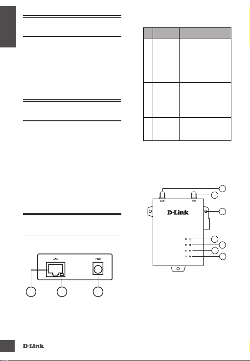
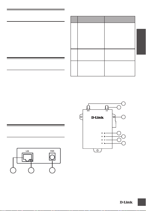
Front Panel
# Item Description
Ethernet
1
Port
Ethernet
2
Activity
DC
3
Power
Input
Table 1
Top Panel
This is a standard
10/100 Mbps
Ethernet port to
connect any device
via Cat 5/5e/6 RJ-45
cables.
Flashes green when
there is Ethernet
trac.
5.5 mm barrel
connector for
power.
1
2
3
4
5
6
7
1
2
2
Figure 1
3
Figure 2
DW M-312
Page 3
# Item Description
SMA
Main
SMA
AUX
Wall
Mounts
1
1
SMA female connector
- Primary antenna.
SMA female connector
- Auxiliary Antenna.
Wall mounts
for standard
8 gauge (4 mm) screws.
A green LED indicates
the DWM-312 is
receiving power.
A green LED indicates
Internet connectivity.
Connected
Solid
to SIM A LTE
Green
Network.
Fallback to
Flashing
SIM A 3G/2G
Green
network.
Connected
Solid
to SIM B LTE
Blue
Network.
Fallback to
Flashing
SIM B 3G/2G
Blue
network.
No Service/
O
SIM Error/
APN Error.
Indicates
Green
strong
signal.
Indicates fair
Amber
Table 2
Red
O
signal.
Indicates
weak signal.
Indicates no
signal.
1
Connector
2
Connector
3
4 Power
5 Internet
6 Network
7 Signal
1
Included antennas are interchangeable, but
third party antennas may not be.
DW M-312
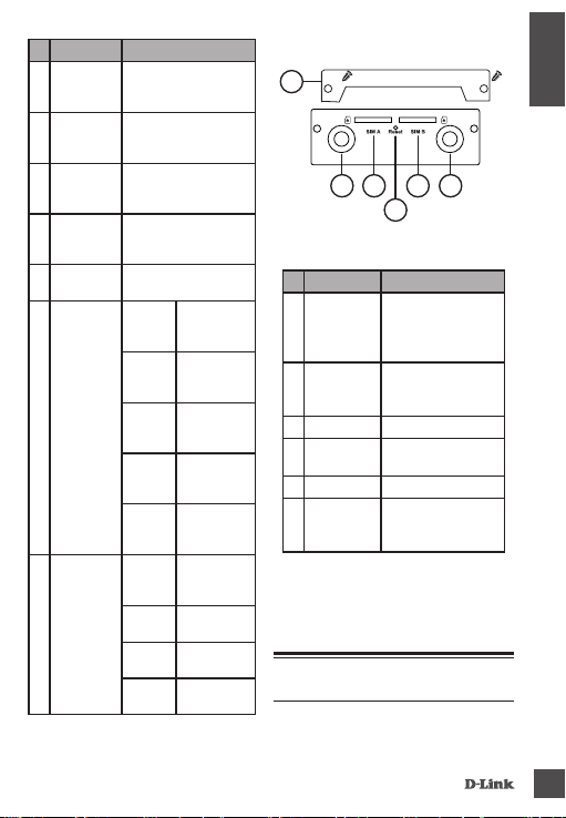
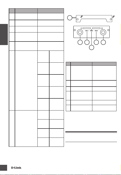
Rear Panel
1
3 5
2
6
4
Figure 3
# I tem Description
Security
1
Plate
SMA
2
Connector
AUX
3 SIM A Primary SIM card
4 Reset
5 SIM B Secondar y SIM card
SMA
6
Connector
Main
1
Included antennas are interchangeable,
but third party antennas may not be.
Table 3: Back Panel
Security plate
covering the SIM
card slots containing
two screw holes
connector - Auxiliary
1
Press and hold for 3
seconds to reset
connector - Primary
1
SMA female
Antenna
SMA female
antenna
Hardware Installation
Before You Begin
ENGLISH
3
Page 4
Observe the following precautions to help
prevent shutdowns, equipment failures, and
personal injury:
ENGLISH
• Install the DWM-312 in a cool and dry place.
Refer to the technical specications in the
user manual for the acceptable operating
temperature and humidity ranges.
• Install the router in a site free from strong
electromagnetic sources, vibration, dust,
excessive moisture, and direct sunlight.
• Place antennas in an unobstructed area
with clear mobile signal. Avoid metal boxes,
brick walls, and other dense materials. It is
recommended to use the web interface to
conrm signal strength before permanent
installation.
• Visually inspect the power connector and
make sure that it is fully secure.
• Do not stack any devices on top of the router.
Installing SIM card(s)
The DWM-312 is equipped with dual-SIM
slots. At least one active SIM card with Internet
access is required for proper operation.
1. Unscrew two screws to remove the security
plate and get access to SIM card slots
2. Insert a micro-SIM card into the slot labelled
SIM A with the contacts facing down. If you
wish to install a second SIM card, insert it
into the slot labelled SIM B.
Figure 4: Installing a micro-SIM card
1. Gently press the micro-SIM into the slot until
it locks into place. To remove, press again and
the SIM card will be ejected.
2. Screw the security plate back on using the
two screws removed earlier in order to
protect the SIM card slots.
Note: SIM behavior must be congured from
the web UI before an Internet connection can
be established.
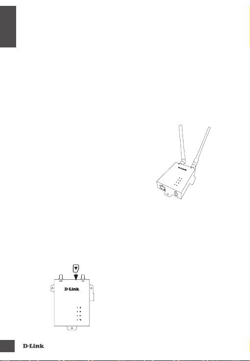
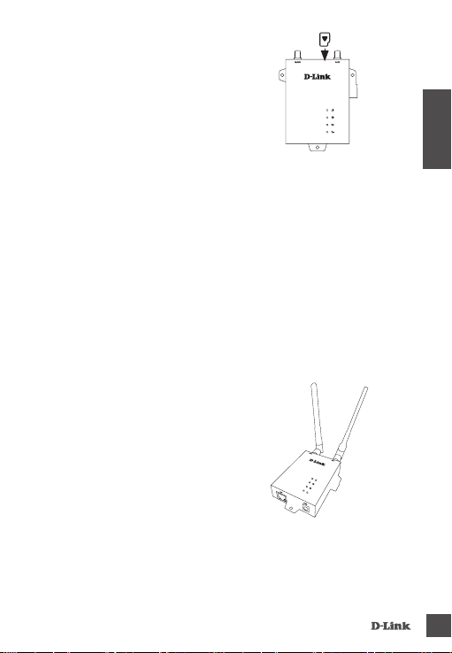
Attach the External Antennas
Figure 5: Attaching External Antennas
The DWM-312 requires two external antennas
to function correctly. The included antennas are
interchangeable, but third party antennas may
require connection to specic ports.
1. Attach the antennas to the SMA connectors
on the back of the router to the ports labelled
“Main” and “Aux.” Turn clockwise to fasten the
antenna.
2. Place antennas where they will receive
optimal signal. Arrange them so they point
upward.
4
DW M-312
Page 5
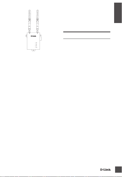
Figure 6: Attaching Antenna to Modem
Note: The included antennas are
interchangeable. Third party antennas may
require connection to specic ports.
Powering the Router
The router features a flexible power input
ranging from 5 volts/2 amps to 18 volts/0.7
amps. A minimum of 10 watts total power is
recommended.
Using the Included AC Adapter
1. Attach the barrel connector of included AC
adapter to the DWM-312 power port on the
front panel.
2. Attach the AC adapter to an appropriate AC
socket.
Connecting Devices
After the DWM-312 has been successfully
installed, the router can be connected to the end
device via the following connection method:
Over Ethernet
The Ethernet port can be connected to an end
device. Use a standard Category 5/5e/6 RJ-45
Ethernet cable to connect the end device to the
DW M-312
router. The port will auto-negotiate to the
highest possible port speed based on the
connected device. Note that the DWM-312
supports a maximum transfer speed of 100
Mbps over Ethernet.
Management Options
Before You Begin
The D-Link router can be managed by
using the Web User Interface (Web UI), or
Simple Network Management Protocol
(SNMP) management interfaces. If you
wish to manage a single D-Link router,
the Web UI may be the best option.
Each router must be assigned its own IP
address, which is used for communication
with the management PC. Please refer to
the following installation instructions to
get started with the Web UI and SNMP
management interfaces.
Web User Interface
Once the router has been successfully
installed, you can begin configuration,
monitor the LED panel, and display
graphical statistics using a web browser.
Supported browsers include: Microsoft®
Internet Explorer , Firefox, Chrome, and
Safari.
You need the following equipment to
access the Web UI of your device:
• A PC with a RJ-45 Ethernet port
• A standard Ethernet cable
ENGLISH
5
Page 6

1. Connect the Ethernet cable to the router’s
Ethernet port and to the Ethernet port on
the PC.
ENGLISH
2. Congure the PC’s IP address to be in the
network segment as the router. The router’s
default IP address is 192.168.0.1, with
subnet mask 255.255.255.0.
3. For example, to connect to the router using
the default settings, your PC should have an
IP address in the range: 192.168.0.2-.254
and a subnet mask of 255.255.255.0.
4. Open the web browser and enter
http://192.168.0.1/ in the address box.
5. Log in to the router. The default user name is
admin and the default password is admin.
SNMP
You can manage the router with D-Link
D-View, or any other SNMP-compatible
program. The SNMP function is disabled by
default and must be enabled on the router
rst by using the Web UI, as described in the
previous section. The D-View SNMP Network
Management System is a comprehensive
standard-based management tool designed
to centrally manage critical network
infrastructure. D-View provides useful tools
to allow network administrators to eectively
manage device congurations, fault tolerance,
performance, and security.
D-Link oers a free version of D-View which
can allow you to manage up to 25 devices. You
can download or get more information on the
following website: http://dview.dlink.com/.
Additional Information
If you are encountering problems setting up
your network, please refer to the user manual.
It contains much more detailed information to
get you up and running with your network.
Additional help is available through our oces
listed at the back of the user manual or online.
To nd out more about D-Link products or
marketing information, please visit the D-Link
website at: http://www.dlink.com/.
TECHNICAL SUPPORT
6
eu.dlink.com/support
DW M-312
Page 7
Vor der Inbetriebnahme
Diese Installationsanleitung führt Sie
schrittweise durch die Einrichtung Ihres
DWM-312 4G LTE M2M Routers. Beachten
Sie, dass das von Ihnen erworbene Modell
sich möglicherweise geringfügig von
denen der Abbildungen unterscheidet.
Detaillierte Informationen zum Router
nden Sie im Benutzerhandbuch.
Packungsinhalt
Dieses DWM-312-Paket sollte
folgende Artikel beinhalten:
• DWM-312
• Netzteil mit 5,5 mm DC-Stecker
• RJ-45-Kabel
• 2 Austauschbare Blade-Antennen
• Installationsanleitung
• Garantiekarte
Sollte einer der oben aufgeführten
Artikel fehlen oder beschädigt
sein, wenden Sie sich bitte an Ihren
lokalen D-Link Fachhändler.
Nr. Ref. Beschreibung
Dies ist ein 10/100
Mbit/s Standard-
1
Ethernet-Port
2
Ethernet-Aktivität
3
Stromversorgung
DC-
Ethernet-Port, um
Geräte über Kat.
5/5e/6 RJ-45-Kabel
anzuschließen.
Blinkt grün bei
Ethernet-Aktivität.
Stromanschluss für
5,5mm DC-Stecker
Tabelle 1
Oberseite
2
DEUTSCH
1
3
Hardware-Überblick
Vorderseite
1
DW M-312
2
Ansicht 1
4
5
6
7
Ansicht 2
3
7
Page 8
Nr. Item Description
1
SMA-Buchse AUX
2
Wandhalterungen
3
Strom
4
DEUTSCH
Internet
5
Netzwerk
6
Signal
7
1
Die mitgelieferten Antennen sind
austauschbar, Antennen von Drittanbietern
können die Sende/Empfangseigenschaften
beeinträchtigen.
Antenne
SMA-Buchse -
1
Zusatzantenne
Wandhalterungen für 4
mm Standardschrauben
Eine grüne LED zeigt
an, dass der DWM-312
Strom erhält.
Eine grüne
LED zeigt eine
Internetverbindung an.
Dauerhaft
grün
Blinkt
grün
Dauerhaft
blau
Blinkt
blau
Aus Kein
Grün Zeigt ein
Gelb Zeigt ein
Rot Zeigt ein
Aus Zeigt ein
SMA-Buchse - Primäre
1
SMA Buchse
Tabelle 2
8
Mit SIM A
LTENetzwerk
verbunden.
Fallback
auf SIM A
3G/2GNetzwerk
Mit SIM B
LTENetzwerk
verbunden.
Fallback
auf SIM B
3G/2GNetzwerk
Service/SIMFehler/APNFehler.
starkes
Signal an.
mittelstarkes
Signal an.
schwaches
Signal an.
fehlendes
Signal an.
Rückseite
1
1 2 435
Ansicht 3
Nr. R ef. Beschreibung
Sicherheitsplakette
1
SMA-Buchse AUX
2
SIM A
3
Zurücksetzen
4
SIM B
5
SMA Buchse
6
1
Die mitgelieferten Antennen sind
austauschbar, Antennen von Drittanbietern
können die Sende/Empfangseigenschaften
beeinträchtigen.
Die Sicherheitsplakette
die den SIMKarteneinschub
abdeckt, hat zwei
Schraubenbohrungen
SMA-Buchse -
1
Zusatzantenne
Primäre SIM-Karte
Zum Zurücksetzen 3
Sekunden gedrückt
halten
Sekundäre SIM-Karte
SMA-Buchse - Primäre
1
Antenne
Tabelle 3: Rückseite
Hardware-Installation
Vor der Inbetriebnahme
Beachten Sie die folgenden
Vorsichtsmaßnahmen, um Ausfälle,
Gerätefehler und Verletzungen
bei Personen zu verhindern:
DW M-312
Page 9
• Installieren Sie den DWM-312 an einem
kühlen und trockenen Ort. Lesen Sie die
Technischen Spezifikationen bezüglich
akzeptabler Betriebstemperaturen und
Feuchtigkeitsbereiche.
• Installieren Sie den Switch an einem
Ort ohne starke elektromagnetische
Quellen, Vibrationen, Staub oder direktes
Sonnenlicht.
• Platzieren Sie Antennen in einem Bereich
ohne Hindernisse, mit klarem mobilem
Signal. Vermeiden Sie Metallkästen,
Steinwände und andere dichte Materialien.
Es ist ratsam, die Weboberfläche zu
verwenden, um vor einer dauerhaften
Installation die Signalstärke zu überprüfen.
• Überprüfen Sie den Netzstecker und achten
Sie darauf, dass er fest eingesteckt ist.
• Stapeln Sie keine anderen Geräte auf dem
Router.
Einsetzen von SIM-Karte(n)
Der DWM-312 ist mit zwei SIM-Steckplätzen
ausgestattet. Mindestens eine SIM-Karte mit
Internetzugang ist für den korrekten Betrieb
erforderlich.
1. Lösen Sie die beiden Schrauben, um die
Sicherheitsplakette zu entfernen und
Zugang zum SIM-Karteneinschub zu haben
2. Setzen Sie eine Micro-SIM-Karte in den
Schlitz mit der Kennzeichnung SIM A.
Die Kontakte müssen nach unten zeigen.
Wenn Sie eine zweite SIM-Karte einsetzen
möchten, setzen Sie diese in den Schlitz mit
der Kennzeichnung SIM B ein.
DW M-312
Ansicht 4:
Einsetzen einer
Micro-SIM-Karte
1. Drücken Sie die Micro-SIM-Karte leicht in den
Schlitz, bis sie einrastet. Um sie zu entfernen,
drücken Sie wieder, die SIM-Karte wird
ausgeworfen.
2. Befestigen Sie die Sicherheitsplakette wieder
mit den beiden zuvor entfernten Schrauben,
um den SIM-Karteneinschub zu schützen.
Hinweis: Das SIM-Verhalten muss über
die Web-UI konfiguriert werden, ehe eine
Internetverbindung hergestellt werden kann.
Anbringen der externen
Antennen
Ansicht 5: Anbringen der externen
Der DWM-312 braucht zwei externe
Antennen für den korrekten Betrieb. Die
mitgelieferten Antennen sind austauschbar,
Antennen
DEUTSCH
9
Page 10

die Antennen von Drittanbietern benötigen
jedoch möglicherweise spezielle SteckerAdapter.
1. Bringen Sie die Antennen an den SMABuchsen auf der Rückseite des Routers an
den Ports mit der Kennzeichnung „Main“ und
„Aux“ an. Drehen Sie im Uhrzeigersinn, um die
Antennen festzudrehen.
2. Platzieren Sie die Antennen an einem Ort, an
DEUTSCH
dem sie ein optimales Signal erhalten. Richten
Sie sie so aus, dass sie nach oben zeigen.
1. Bringen Sie den DC-Stecker
des mitgelieferten Netzteils am
Stromanschluss des DWM-312 auf der
Vorderseite an.
2. Verbinden Sie das Netzteil mit einer
entsprechenden Steckdose.
Geräte verbinden
Nach der erfolgreichen Installation können
Endgeräte wie folgt mit dem Router
verbunden werden:
Über Ethernet
Der Ethernet-Port kann mit einem Endgerät
verbunden werden. Verwenden Sie ein
Standard-Ethernet-Kabel der Kategorie
5/5e/6 RJ-45, um das Endgerät mit dem
Router zu verbinden. Der Port wird
automatisch die höchstmögliche PortGeschwindigkeit für das angeschlossene
Gerät wählen. Beachten Sie, dass der
DWM-312 eine maximale Geschwindigkeit
von 100 Mbit/s über Ethernet unterstützt.
Ansicht 6: Anbringen der
Antennen am Router
Hinweis: Die mitgelieferten Antennen sind
austauschbar, die Antennen von Drittanbietern
benötigen jedoch möglicherweise spezielle
Stecker-Adapter.
Einschalten des Routers
Der Router hat einen flexiblen
Stromversorgungsbereich von 5 Volt/2Ampere
bis 18 Volt/0,7 Ampere. Mindestens 10 Watt
Gesamtleistung sind empfohlen.
Verwendung des
mitgelieferten Netzteils
10
Management-Optionen
Vor der Inbetriebnahme
Der D-Link Router kann über die
Schnittstellen Web-Benutzeroberfläche
(Web-UI), oder ein Simple Network
Management Protocol (SNMP) verwaltet
werden. Wenn Sie einen einzelnen
D-Link-Router verwalten möchten, ist
die Web-UI vermutlich die beste Option.
Jedem Router muss seine eigene IPAdresse zugewiesen werden, die für die
Kommunikation mit dem ManagementPC verwendet wird. Bitte lesen Sie die
folgende Installationsanleitung für
den Einstieg in die Web-UI und die
SNMP Management-Schnittstellen.
DW M-312
Page 11

Web-Benutzeroberäche
Nach der erfolgreichen Installation des
Routers können Sie mit der Konguration
beginnen, das LED-Bedienfeld überwachen
und grafische Statistiken über einen
Webbrowser aufrufen. Unterstützte
Browser sind: Microsoft® Internet Explorer ,
Firefox, Chrome und Safari.
Sie benötigen die folgende Ausrüstung,
um die Web-UI Ihres Gerätes aufzurufen:
• einen PC mit einem RJ-45 Ethernet-Port
• ein Standard-Ethernet-Kabel
1. Schließen Sie das Ethernet-Kabel am
Ethernet-Port des Routers und am
Ethernet-Port des PC an.
2. Konfigurieren Sie die IP-Adresse
des PC so, dass sie sich im selben
Netwerksegment befindet wie der
Router. Die Standard-IP-Adresse des
Routers lautet 192.168.0.1, mit der
Subnetzmaske 255.255.255.0.
3. Um den Router beispielsweise mit den
Standardeinstellungen zu verbinden,
sollte Ihr PC eine IP-Adresse im folgenden
Bereich haben: 192.168.0.2-.254 und eine
Subnetzmaske von 255.255.255.0.
4. Ö nen Sie einen Webbrowser und geben
Sie im Adressfeld http://192.168.0.1/
ein.
5. Melden Sie sich am Router an. Der
Standard-Benutzername ist admin, das
Standard-Kennwort ist admin.
SNMP
Sie können den Router mit D-Link D-View
oder einem anderen mit SNMP kompatiblen
Programm verwalten. Die SNMP-Funktion
ist standardmäßig deaktiviert und
muss erst am Router über die Web-UI
TECHNISCHE UNTERSTÜTZUNG
aktiviert werden, wie im vorigen Bereich
beschrieben. Das D-View SNMP Network
Management System ist ein umfassendes,
Standard-basiertes Management-Tool, das
zur zentralen Verwaltung einer kritischen
Netzwerk-Infrastruktur entwickelt wurde.
D-View bietet nützliche Tools, die es
Netzwerk-Administratoren erlauben, die
Gerätekongurationen, die Fehlertoleranz,
Leistung und Sicherheit effektiv zu
verwalten.
D-Link bietet eine kostenloses Version von
D-View an, mit der Sie bis zu 25 Geräte
verwalten können. Sie können sie auf der
folgenden Seite herunterladen, auf der
Sie auch weitere Informationen nden:
http://dview.dlink.com/.
Weitere Informationen
Wenn Sie Probleme bei der Einrichtung
Ihres Netzwerks haben, lesen Sie bitte
das Benutzerhandbuch. Es enthält
detailliertere Informationen zur
Einrichtung Ihres Netzwerks.
Zusätzliche Hilfe erhalten Sie über die
Niederlassungen, die auf der Rückseite des
Benutzerhandbuchs aufgelistet sind, oder
online. Um mehr über D-Link-Produkte zu
erfahren oder Marketinginformationen zu
erhalten, besuchen Sie die D-Link Website
unter: http://www.dlink.com/.
eu.dlink.com/support
DEUTSCH
DW M-312
11
Page 12

Avant de commencer
Ce guide d’installation rapide vous fournit
des instructions pas à pas pour congurer
votre routeur DWM-312 4G LTE M2M.
Le modèle que vous avez acheté peut
légèrement diérer de celui illustré. Pour des
informations plus détaillées sur le routeur,
reportez-vous au manuel de l’utilisateur.
Contenu de la boîte
Le paquet du DWM-312 doit
comprendre les éléments suivants:
• DWM-312
FRANÇAIS
• Adaptateur secteur avec
connecteur CC 5,5 mm
• Câble RJ -45
• [2] Antennes sabres interchangeables
• Guide d’installation rapide
• Carte de garantie
Si l’un des éléments ci-dessus est
endommagé ou manquant, contactez
votre revendeur local D-Link.
Description du matériel
Façade
# Élément Description
Il s’agit d’un port
Ethernet 10/100
1
Port Ethernet
2
Activité Ethernet
Entrée
3
d'alimentation CC
Mbps standard pour
connecter tous les
périphériques via
des câbles RJ-45 de
catégorie 5/5e/6.
Clignote en vert
lorsqu'il existe un
trac Ethernet.
Connecteur barillet
5,5 mm pour
l'alimentation.
Table 1
Panneau supérieur
2
4
6
1
3
5
7
1
12
2
Figure 1
3
Figure 2
DW M-312
Page 13

#
Élément Description
SMA
murales
1
1
Connecteur femelle SMA Antenne principale.
Connecteur femelle SMA Antenne auxiliaire.
Monture murale pour
vis de gabarit standard 8
(4 mm).
Une LED verte indique
que le DWM-312 est sous
tension.
Une LED verte indique la
connectivité Internet.
Connecté à
un réseau SIM
Vert xe
A LTE.
Repli
automatique
Vert
sur le réseau
clignotant
SIM A 3G/2G.
Connecté à
un réseau SIM
Bleu xe
B LTE.
Repli
automatique
Bleu
sur le réseau
clignotant
SIM B 3G/2G.
Pas de service/
erreur SIM/
Éteint
erreur APN
Indique un
Vert
signal fort.
Indique un
Orange
signal correct.
Indique un
Rouge
signal faible.
Indique une
absence de
Éteint
signal.
Connecteur
1
principal
Connecteur
2
AUX SMA
Montures
3
4 Alimentation
5 Internet
6 Réseau
7 Signal
1
Les antennes incluses sont interchangeables,
mais des antennes tierces peuvent ne pas l’être
Table 2
DW M-312
Panneau arrière
1
1 2 435
Figure 3
#
Élément Description
Plaque de
1
sécurité
Connecteur
2
AUX SMA
3
4
Réinitialisation
5
Connecteur
6
principal SMA
1
Les antennes incluses sont
interchangeables, mais des antennes
tierces peuvent ne pas l’être.
SIM A
SIM B
Plaque de sécurité
recouvrant
les logements
pour carte SIM
comportant deux
orices pour vis
Connecteur femelle
SMA - Antenne
1
auxiliaire
Principale carte SIM
Appuyez de
manière prolongée
pendant 3secondes
pour réinitialiser
Carte SIM
secondaire
Connecteur femelle
SMA - Antenne
1
principale
Table 3: Panneau arrière
Installation du matériel
.
Avant de commencer
FRANÇAIS
13
Page 14

Respectez les précautions suivantes
afin d’éviter tout risque d’arrêt, de
dysfonctionnement de l’équipement ou de
blessures corporelles:
• Installez le DWM-312 dans un endroit frais
et sec. Reportez-vous aux caractéristiques
techniques du manuel de l’utilisateur pour
trouver les plages de fonctionnement
acceptables de température et d’humidité.
• Installez le routeur dans un endroit exempt
de sources de champs électromagnétiques
intenses, de vibrations, de poussière,
d’humidité excessive et à l’abri des rayons
du soleil.
• Posez les antennes dans une zone dégagée
FRANÇAIS
avec un signal mobile net. Évitez les boîtes
métalliques, les parois en brique et les
autres matériaux denses. Il est recommandé
d’utiliser l’interface Web pour confirmer
l’intensité du signal avant une installation
dénitive.
• Inspectez visuellement le connecteur
d’alimentation et assurez-vous qu’il est
bien xé.
• N’empilez pas d’appareils sur le routeur.
Installation de là ou des cartes SIM
Le DWM-312 est équipé de deux
emplacements SIM. Au moins une carte SIM
active avec accès Internet est nécessaire pour
un bon fonctionnement.
1. Dévissez les deux vis pour retirer la plaque
de sécurité et accéder aux emplacements
pour carte SIM
2. Insérez une carte micro-SIM dans
l’emplacement étiqueté SIM A avec
les contacts dirigés vers le bas. Si vous
souhaitez installer une seconde carte SIM,
insérez-la dans l’emplacement étiqueté
SIM B.
14
Figure 4:
Installation d’une
carte micro-SIM
1. Enfoncez doucement la carte micro-SIM
dans l’emplacement jusqu’à ce qu’elle se
verrouille en position. Pour la retirer, appuyez
à nouveau dessus et la carte SIM est éjectée.
2. Revissez la plaque de sécurité à l’aide des
deux vis retirées précédemment afin de
protéger les logements de carte SIM.
Remarque: Le comportement SIM doit
être configuré depuis l’interface utilisateur
Web avant de pouvoir établir une connexion
Internet.
Fixation des antennes externes
Figure 5:
Fixation des antennes
externes
DW M-312
Page 15

Le DWM-312 nécessite deux antennes
externes pour fonctionner correctement. Les
antennes incluses sont interchangeables, mais
des antennes tierces peuvent nécessiter une
connexion à des ports particuliers.
1. Fixez les antennes sur les connecteurs SMA
à l’arrière du routeur, sur les ports étiquetés
« Main » (Principal) et « Aux » (Auxiliaire).
Tournez dans le sens des aiguilles d’une
montre pour xer l’antenne.
2. Placez les antennes à un endroit où elles
recevront un signal optimal. Disposez-les
pour qu’elles pointent vers le haut.
Figure 6:
Fixation de l’antenne modem
Remarque : Les antennes incluses sont
interchangeables. Des antennes tierces
peuvent nécessiter une connexion à des ports
particuliers.
Alimentation du routeur
Le routeur dispose d’une entrée d’alimentation
flexible de 5 volts/2 ampsère à 18 volts/0,7
ampère. Une puissance minimale totale de 10
Watts est recommandée.
DW M-312
Utilisation de l’adaptateur
secteur inclus
1. Fixez le connecteur à barillet
de l’adaptateur secteur sur le port
d’alimentation du DWM-312 sur le
panneau avant.
2. Branchez l’adaptateur secteur sur une
prise d’alimentation secteur appropriée.
Connexion de périphériques
Une fois le DWM-312 correctement
installé, le routeur peut être connecté
au périphérique nal via la méthode de
connexion suivante:
Sur Ethernet
Le port Ethernet peut être connecté à
un périphérique final. Utilisez un câble
Ethernet standard de catégorie 5/5e/6
RJ-45 pour raccorder le périphérique
terminal au routeur. Le port négocie
automatiquement la vitesse de port
la plus élevée possible en fonction du
périphérique connecté. Veuillez noter
que le DWM-312 prend en charge une
vitesse de transfert maximal de 100 Mbps
sur Ethernet.
Options de gestion
Avant de commencer
Le routeur D-Link peut être géré en utilisant
l’interface utilisateur Web (Web UI), ou
des interfaces de gestion SNMP (Simple
Network Management Protocol). Si vous
souhaitez gérer un seul routeur D-Link,
l’interface utilisateur Web peut être la
meilleure option. Chaque routeur doit
avoir sa propre adresseIP pour assurer
la communication avec le PC de gestion.
Veuillez vous reporter aux instructions
FRANÇAIS
15
Page 16

suivantes pour démarrer l’installation
avec l’interface utilisateur Web, le DNA,
le port console, et le programme SNMP.
Interface utilisateur Web
Une fois que le routeur a été installé
avec succès, vous pouvez commencer la
conguration, surveiller le panneau à LED
et acher les statistiques graphiquement à
l’aide d’un navigateur Web Les navigateurs
pris en charge comprennent: Microsoft®
Internet Explorer , Firefox, Chrome et Safari.
Vous avez besoin du matériel suivant
pour accéder à l’interface Web de votre
périphérique:
• Un PC doté d’un port Ethernet RJ-45
FRANÇAIS
• Un câble Ethernet standard
1. Connectez le câble Ethernet sur le port
Ethernet du routeur et sur le port Ethernet
du PC.
2. Congurez l’adresse IP du PC pour qu’elle
se trouve dans le même segment de réseau
que le routeur. L’adresse IP par défaut du
routeur est 192.168.0.1, avec le masque
de sous-réseau 255.255.255.0.
3. Par exemple, pour vous connecter au
routeur en utilisant les paramètres par
défaut, votre PC doit avoir une adresse
IP dans la plage: 192.168.0.2-.254 et un
masque de sous-réseau de 255.255.255.0.
4. Ouvrez le navigateur Web et saisissez
http://192.168.0.1/ dans la zone d’adresse.
5. Connectez-vous au routeur. Le nom
d’utilisateur par défaut est admin et le mot
de passe est admin.
SNMP
Vous pouvez gérer le routeur à l’aide de
D-Link D-View ou de n’importe quel autre
programmeSNMP compatible. La fonction
SNMP est désactivée par défaut et doit
d’abord être activée sur le routeur en utilisant
l’interface utilisateur Web, comme expliqué
dans la section précédente. Le système
de gestion de réseau SNMP D-View est
un outil de gestion normalisé complet,
conçu pour gérer l’infrastructure critique
du réseau de manière centralisée. D-View
dispose d’outils utiles, qui permettent aux
administrateurs réseau de gérer ecacement
les congurations des dispositifs, la tolérance
aux pannes, la performance et la sécurité.
D-Link offre une version gratuite de
D-View, qui vous permet de gérer
jusqu’à 25 périphériques. Vous pouvez
télécharger l’application ou obtenir plus
d’informations sur le site Web suivant:
http://dview.dlink.com/.
Informations
complémentaires
Si vous rencontrez des problèmes pour
congurer votre réseau, consultez le mode
d’emploi. Il contient des informations
beaucoup plus détaillées pour vous aider à
rendre votre réseau opérationnel.
Vous trouverez une aide supplémentaire
auprès de nos bureaux répertoriés au dos
du manuel de l’utilisateur et en ligne. Pour
en savoir plus sur les produits D-Link ou
pour obtenir des informations commerciales,
consultez le site Web de D-Link à:
http://www.dlink.com/.
ASSISTANCE TECHNIQUE
16
eu.dlink.com/support
DW M-312
Page 17

Antes de empezar
Esta guía de instalación rápida le ofrece
instrucciones paso a paso para congurar
el router DWM-312 4G LTE M2M. El
modelo que ha adquirido puede tener
un aspecto ligeramente diferente al
mostrado en las ilustraciones. Para
obtener información más detallada sobre
el router, consulte el manual del usuario.
Contenido de la caja
La caja de este DWM-312 debe
incluir los elementos siguientes:
• DWM-312
• Adaptador de CA con conector
de CC de 5,5 mm
• Cable RJ-45
• [2] Antenas intercambiables
• Guía de instalación rápida
• Tarjeta de garantía
Si cualquiera de los artículos anteriores
falta o está dañado, póngase en contacto
con su proveedor local de D-Link.
Descripción general del
hardware
Panel frontal
# Elemento Descripción
Se trata de un
puerto Ethernet
10/100 Mbps
estándar que
1 Puerto Ethernet
Actividad de
2
Ethernet
Entrada de
3
alimentación CC
permite conectar
cualquier
dispositivo
mediante cables
RJ-45 de la cat.
5/5e/6
Parpadea en verde
si hay tráco
Ethernet.
Conector de 5,5 mm
para alimentación.
Table 1
.
Panel superior
2
4
6
ESPAÑOL
1
3
5
7
1
DW M-312
2
Figure 1
3
17
Page 18

Figure 2
# Elemento Descripción
Conector SMA
1
principal
Conector SMA
2
Montajes
3
para pared
4 Alimentación
5 Internet
6 Red
ESPAÑOL
auxiliar
Conector SMA hembra antena principal.
1
Conector SMA hembra antena auxiliar.
1
Montajes de pared para
tornillos estándar de
calibre 8 (4 mm).
Un LED verde indica
que el DWM-312 está
recibiendo alimentación.
Un LED verde indica
conectividad a Internet.
Verde
continuo
Parpadeo
en verde
Azul
continuo
Parpadeo
en azul
Apagado Sin servicio/
Verde Indica señal
Ámbar Indica señal
7 Señal
Rojo Indica señal
Apagado Indica ausencia
1
Las antenas incluidas son intercambiables,
pero es posible que las de otros fabricantes
no lo sean
.
Table 2
18
Conectado
a red LTE de
SIM A.
Repliegue a
red 3G/2G de
SIM A.
Conectado
a red LTE de
SIM B.
Repliegue a
red 3G/2G de
SIM B.
Error de SIM/
Error de APN.
intensa.
aceptable.
débil.
de señal.
Panel posterior
1
1 2 435
Figure 3
# Elemento Descripción
Placa de
1
seguridad
Conector SMA
2
auxiliar
3
4
Reiniciar
5
Conector SMA
6
principal
1
Las antenas incluidas son intercambiables,
pero es posible que las de otros fabricantes
no lo sean.
SIM A
SIM B
Placa de seguridad
que cubre las
ranuras para tarjeta
SIM con dos oricios
para tornillos.
Conector SMA
hembra - antena
1
auxiliar
Tarjeta SIM principal
Pulse y mantenga
pulsado durante
3 segundos para
reiniciar
Tarjeta SIM
secundaria
Conector SMA
hembra - antena
1
principal
Table 3: Panel posterior
Instalación del hardware
Antes de empezar
DW M-312
Page 19

Respete las precauciones siguientes para
ayudar a evitar paradas, errores del equipo
y lesiones personales:
• Instale el DWM-312 en un lugar fresco
y seco. Consulte las especificaciones
técnicas del manual del usuario para ver
los intervalos de temperatura y humedad
en funcionamiento aceptables.
• Instale el router en un lugar en el que
no existan fuentes electromagnéticas
intensas, vibraciones, polvo, exceso de
humedad ni luz solar directa.
• Coloque las antenas en una zona
despejada con una clara señal móvil.
Evite cajas de metal, paredes de ladrillo y
otros materiales densos. Se recomienda
el uso de la interfaz web para conrmar
la intensidad de la señal antes de la
instalación permanente.
• Inspeccione visualmente el conector
de alimentación y compruebe que está
debidamente protegido.
• No apile ningún dispositivo encima
del router.
Instalación de tarjeta(s) SIM
El DWM-312 está equipado con ranuras SIM
duales. Se requiere al menos una tarjeta
SIM activa con acceso a Internet para un
funcionamiento correcto.
1. Quite dos tornillos para retirar la placa de
seguridad y obtener acceso a las ranuras
para tarjeta SIM.
2. Inserte una tarjeta micro-SIM en la
ranura etiquetada como SIM A, con los
contactos hacia abajo. Si desea instalar
una segunda tarjeta SIM, insértela en la
ranura etiquetada como SIM B.
Figure 4:
Instalación de una
tarjeta micro-SIM
1. Presione con suavidad la micro-SIM hacia
el interior de la ranura hasta que encaje en
su sitio. Para retirarla, vuelva a presionarla
y la tarjeta SIM será expulsada.
2. Vuelva a atornillar la placa de seguridad
usando los dos tornillos retirados
anteriormente con el n de proteger las
ranuras para tarjeta SIM.
Nota: Es necesario configurar el
comportamiento de la SIM desde la IU web
para poder establecer una conexión a Internet.
Acoplar las antenas externas
Figure 5:
Acoplamiento de las
antenas externas
ESPAÑOL
DW M-312
19
Page 20

El DWM-312 precisa dos antenas externas
para funcionar correctamente. Las antenas
incluidas son intercambiables; sin embargo,
las antenas de otros fabricantes podrían
precisar su conexión a puertos especícos.
1. Acople las antenas a los conectores SMA
situados en la parte posterior del router, a
los puertos marcados como “Main” y “Aux.”
Gire en el sentido de las agujas del reloj
para apretar la antena.
2. Coloque las antenas donde reciban una
señal óptima. Dispóngalas de modo que
queden dirigidas hacia arriba.
ESPAÑOL
Figure 6:
Acoplamiento de
la antena al módem
Nota: Las antenas incluidas son
intercambiables. Las antenas de otros
fabricantes podrían precisar su conexión a
puertos especícos.
Alimentación del router
El router cuenta con una entrada de
alimentación flexible, desde 5 voltios/2
amperios hasta 18 voltios/0,7 amperios. Se
recomienda una potencia total de 10 vatios
como mínimo.
20
Uso del adaptador de CA
incluido
1. Acople el conector de barril del
adaptador de CA incluido en el puerto
de alimentación DWM-312 del panel
frontal.
2. Acople el adaptador de CA a una toma
de CA adecuada.
Conexión de dispositivos
Una vez instalado correctamente el
DWM-312, se puede conectar el router
al dispositivo nal mediante el siguiente
método de conexión:
Sobre Ethernet
El puerto Ethernet se puede conectar
a un dispositivo nal. Utilice un cable
Ethernet RJ-45 estándar de categoría
5/5e/6 para conectar el dispositivo
final al router. El puerto realizará una
negociación automática a la velocidad de
puerto más elevada posible en función
del dispositivo conectado. Tenga en
cuenta que el DWM-312 admite una
velocidad de transferencia máxima de
100 Mbps sobre Ethernet.
Opciones de gestión
Antes de empezar
El router D-Link se puede gestionar
utilizando la interfaz de usuario web
(IU web), o las interfaces de gestión del
protocolo simple de gestión de redes
(SNMP). Si desea gestionar un único
router D-Link, puede que la interfaz de
usuario web sea la mejor opción. Se debe
asignar a cada router su propia dirección
IP, que se utiliza para la comunicación
con el PC de gestión. Consulte las
DW M-312
Page 21

instrucciones de instalación siguientes
para comenzar con la interfaz de usuario
web y las interfaces de gestión SNMP.
Interfaz de usuario web
Una vez instalado correctamente el router,
puede empezar la conguración, supervisar
el panel de LED y mostrar las estadísticas
grácas utilizando un explorador de web.
Entre los exploradores compatibles se
incluyen: Microsoft® Internet Explorer ,
Firefox, Chrome y Safari.
Necesita el equipo siguiente para
acceder a la interfaz de usuario web del
dispositivo:
• Un ordenador con un puerto Ethernet
RJ-45
• Un cable Ethernet estándar
1. Conecte el cable Ethernet al puerto
Ethernet del router y al puerto Ethernet
del PC.
2. Congure la dirección IP del PC para que
esté en el mismo segmento de red que
el router. La dirección IP predeterminada
del router es 192.168.0.1, con la máscara
de subred 255.255.255.0.
3. Por ejemplo, para conectarse
al router utilizando los parámetros
predeterminados, el PC debe tener
una dirección IP que esté en el rango:
192.168.0.2-.254 y una máscara de
subred de 255.255.255.0.
4. Abra el explorador de Web e introduzca
http://192.168.0.1/ en el cuadro de
direcciones.
5. Inicie sesión en el router. El nombre de
usuario predeterminado es admin y la
contraseña predeterminada, admin.
SNMP
Puede gestionar el router con D-Link
D-View o cualquier otro programa
compatible con SNMP. La función
SNMP está desactivada de manera
predeterminada y se debe activar primero
en el router utilizando la interfaz de usuario
web, como se ha descrito en la sección
anterior. El sistema de gestión de red SNMP
D-View es una completa herramienta de
gestión basada en estándares y diseñada
para gestionar infraestructuras de red
críticas de forma centralizada. D-View
proporciona herramientas útiles que
permiten a los administradores de red
gestionar ecazmente las conguraciones,
la tolerancia a los fallos, el rendimiento y la
seguridad del dispositivo.
D-Link ofrece una versión gratuita de
D-View que puede permitirle gestionar
hasta 25 dispositivos. Puede descargar u
obtener más información en el siguiente
sitio web: http://dview.dlink.com/.
Información adicional
Si tiene problemas al configurar la
red, consulte el manual del usuario
suministrado con el conmutador. Contiene
mucha más información detallada para
que pueda empezar a utilizar la red.
Existe ayuda adicional disponible a
través de nuestras ocinas, que aparecen
enumeradas en la contraportada del
manual de usuario o en línea. Para
encontrar más información acerca de los
productos D-Link o su comercialización,
visite el sitio web de D-Link en:
http://www.dlink.com/.
ESPAÑOL
ASISTENCIA TÉCNICA
DW M-312
eu.dlink.com/support
21
Page 22

Prima di iniziare
1
Questa Guida rapida di installazione ore
istruzioni dettagliate per l’installazione del
Router DWM-312 4G LTE M2M. Il modello
acquistato potrebbe essere leggermente
diverso da quello raffigurato nelle
illustrazioni. Per informazioni più dettagliate
sul router, consultare il manuale dell’utente.
Contenuto della confezione
Questo pacchetto DWM-312 deve
includere i seguenti elementi:
• DWM-312
• Adattatore AC con
connettore CC 5,5 mm
• Cavo RJ-45
• [2] Antenne blade interscambiabili
• Guida di installazione rapida
• Scheda garanzia
Se uno o più degli articoli sopra elencati
risultano danneggiati o mancanti, contattare
il rivenditore D-Link locale.
Panoramica hardware
Pannello frontale
ITALIANO
# Articolo Descrizione
Porta Ethernet
standard 10/100
Mbps per la
CC
connessione
di qualsiasi
dispositivo tramite
cavi Cat 5/5e/6
RJ-45.
Lampeggia in verde
in presenza di
traco Ethernet
Connettore barrel
da 5,5 mm per
l'alimentazione.
Table 1
1 Porta Ethernet
2 Attività Ethernet
Ingresso di
3
alimentazione
Pannello superiore
2
4
6
3
5
7
1
22
2
Figure 1
3
Figure 2
DW M-312
Page 23

# Ar ticolo Descrizione
Rete
1
connettore
Connettore
2
SMA AUX
Installazioni
3
4
Accensione
5
6
7
1
Le antenne incluse sono interscambiabili, ma
le antenne di terzi produttori potrebbero non
esserlo
Connettore femmina SMA Antenna principale.
1
SMA
Connettore femmina SMA Antenna ausiliaria.
1
Installazioni a parete per viti
standard 8 gauge (4 mm).
a parete
Un LED verde indica che
DWM-312 riceve energia
elettrica.
Un LED verde indica la
Internet
connettività a Internet.
Verde sso Connesso a
Verde
lampeggiante
Blu sso Connesso a
Rete
Blu
lampeggiante
O Nessun
Verde Indica
Ambra Indica
Segnale
Rosso Indica
O I ndica
.
una rete SIM
A LTE.
Fallback su
rete SIM A
3G/2G.
una rete SIM
B LTE.
Fallback su
rete SIM B
3G/2G.
servizio/
Errore SIM/
Errore APN.
segnale
forte.
segnale
medio.
segnale
debole.
nessun
segnale.
Table 2
DW M-312
Pannello posteriore
1
1 2 435
Figure 3
# Articolo Descrizione
Targhetta di
1
sicurezza
Connettore
2
SMA AUX
3
4
5
6
connettore
1
Le antenne incluse sono interscambiabili,
ma le antenne di terzi produttori
potrebbero non esserlo.
SIM A
Reset
SIM B
Rete
SMA
Targhetta di
sicurezza per coprire
gli slot della scheda
SIM contenenti due
fori per viti.
Connettore
femmina SMA -
1
Antenna ausiliaria
Scheda SIM
principale
Tenere premuto
per 3 secondi per
reimpostare
Scheda SIM
secondaria
Connettore
femmina SMA -
1
Antenna principale
Table 3: Pannello posteriore
Installazione dell’hardware
Prima di iniziare
ITALIANO
23
Page 24

Per prevenire arresti, malfunzionamenti del
dispositivo e lesioni, osservare le precauzioni
descritte di seguito:
• Installare il DWM-312 in un luogo fresco e
asciutto. Per gli intervalli accettabili relativi
a temperatura e umidità in funzione, fare
riferimento alle specifiche tecniche nel
manuale utente.
• Installare il router in un luogo non soggetto
a forti campi elettromagnetici, lontano da
vibrazioni, polvere, eccessiva umidità e luce
diretta del sole.
• Posizionare le antenne in un’area senza
ostacoli con un segnale mobile chiaro.
Evitare contenitori in metallo, pareti di
mattoni e altri materiali spessi. Si consiglia
di usare l’interfaccia Web per vericare la
potenza del segnale prima dell’installazione
denitiva.
• Ispezionare visivamente il connettore di
alimentazione e assicurarsi che sia ben
ssato.
• Non impilare altri dispositivi sulla parte
superiore del router.
Installazione di schede SIM
DWM-312 è dotato di slot dual-SIM. Per un
corretto funzionamento, è necessaria almeno
ITALIANO
una scheda SIM attiva con accesso a Internet.
1. Svitare le due viti per rimuovere la targhetta
di sicurezza e accedere agli slot della scheda
SIM
2. Inserire una schede micro-SIM nello slot
etichettato come SIM A con i contatti rivolti
verso il basso. Per installare una seconda
scheda SIM, inserirla nello slot etichettato
come SIM B.
24
Figure 4:
Installazione di una
scheda micro-SIM
1. Premere leggermente la scheda microSIM nello slot fino a quando si blocca in
posizione. Per rimuoverla, premere di nuovo
e la scheda SIM sarà espulsa.
2. Riavvitare la targhetta di sicurezza
utilizzando le viti rimosse in precedenza
per proteggere gli slot della scheda SIM.
Nota: il funzionamento SIM deve essere
congurato tramite la UI Web prima di stabilire
la connessione Internet.
Collegare le antenne esterne
Figure 5:
Fissare le antenne esterne
DWM-312 necessita del corretto
funzionamento di due antenne esterne. Le
antenne incluse sono interscambiabili, ma
le antenne di terzi produttori potrebbero
richiedere la connessione a porte speciche.
DW M-312
Page 25

1. Fissare le antenne ai connettori SMA nella
parte posteriore del router alle porte con
le etichette “Main” e “Aux.” Ruotare in senso
orario per ssare l’antenna.
2. Posizionare le antenne in modo che ricevano
il segnale migliore. Disporle in modo che
puntino verso l’alto.
Figure 6:
Fissaggio
dell’antenna al modem
Nota: le antenne incluse sono interscambiabili.
Le antenne di terzi potrebbero richiedere la
connessione a porte speciche.
Accensione del router
Il router è caratterizzato da un ingresso di
energia essibile, che varia da 5 volts/2 amps a
18 volts/0.7 amps. Si consiglia un’alimentazione
minima di 10 watt totale.
Utilizzo dell’adattatore AC
incluso
1. Fissare il connettore barrel dell’adattatore AC
incluso nella porta di alimentazione DWM-
312 nel pannello anteriore.
2. Fissare l’adattatore AC a una presa AC
appropriata.
Connessione dei dispositivi
Dopo avere correttamente installato
DWM-312, il router può essere collegato
al dispositivo finale tramite il seguente
metodo di connessione:
Sulla rete Ethernet
La porta Ethernet può essere collegata a
dispositivo nale. Usare un cavo Ethernet
di categoria 5/5e/6 RJ-45 standard per
connettere il dispositivo nale al router. La
porta eseguirà la negoziazione automatica
alla più elevata velocità di porta possibile
nel dispositivo connesso. DWM-312
supporta una velocità di trasferimento
massima di 100 Mbps su Ethernet.
Opzioni di gestione
Prima di iniziare
È possibile gestire il router D-Link usando
l’interfaccia utente Web (UI Web), o le
interfacce di gestione SNMP (Simple
Network Management Protocol). Per
gestire un singolo router D-Link, l’interfaccia
utente Web può essere l’opzione migliore.
A ogni router deve essere assegnato
un proprio indirizzo IP usato per la
comunicazione con il PC di gestione.
Vedere le seguenti istruzioni di installazione
per un’introduzione all’interfaccia utente
Web e alle interfacce di gestione SNMP.
Interfaccia utente Web
Quando il router è correttamente installato,
è possibile iniziare la configurazione,
monitorare il pannello a LED e visualizzare
le statistiche grache usando un browser
Web. I browser supportati includono:
Microsoft® Internet Explorer , Firefox,
Chrome e Safari.
ITALIANO
DW M-312
25
Page 26

Per accedere all’interfaccia utente Web del
dispositivo è necessario quanto segue:
• Un PC con una porta Ethernet RJ-45
• Un cavo Ethernet standard
1. Collegare il cavo Ethernet a qualsiasi porta
Ethernet del router e alla porta Ethernet nel
PC.
2. Configurare l’indirizzo IP del PC nel
segmento di rete come router. L’indirizzo
IP predenito del router è 192.168.0.1,
mentre la subnet mask è 255.255.255.0.
3. Ad esempio, per collegare il router con le
impostazioni predenite, il PC dovrà avere
un indirizzo IP nell’intervallo: 192.168.0.2.254 e una subnet mask di 255.255.255.0.
4. Aprire un browser Web e immettere
l’indirizzo http://192.168.0.1/ nella barra
degli indirizzi.
5. Accesso al router. Il nome utente predenito
è admin, mentre la password predenita è
admin.
SNMP
È possibile gestire il router tramite D-Link
D-View o qualsiasi altro programma
compatibile SNMP. La funzione SNMP è
ITALIANO
disabilitata per impostazione predefinita
e deve essere abilitata prima nel router
utilizzando l’interfaccia utente Web, come
descritto nella sezione precedente. Il sistema
di gestione delle reti SNMP D-View è uno
strumento di gestione completo basato su
standard, appositamente pensato per la
gestione centralizzata dell’infrastruttura di
rete critica. D-View include utili strumenti
per consentire agli amministratori di rete di
gestire in modo ecace le congurazioni dei
dispositivi, la tolleranza di errore, le prestazioni
e la sicurezza.
D-Link ore una versione gratuita di D-View
che consente di gestire un massimo di 25
dispositivi. È possibile scaricare o ottenere
maggiori informazioni dal seguente sito Web:
http://dview.dlink.com/.
Ulteriori informazioni
In caso di problemi di congurazione della
rete, fare riferimento al Manuale dell’utente.
Contiene informazioni molto più dettagliate
per il corretto funzionamento in rete.
Per ulteriore supporto è possibile rivolgersi
agli uci il cui elenco è riportato sul retro
del manuale dell’utente o è disponibile
online. Per ulteriori informazioni sui
prodotti D-Link o per la documentazione
marketing, visitare il sito Web all’indirizzo:
http://www.dlink.com/.
SUPPORTO TECNICO
26
eu.dlink.com/support
DW M-312
Page 27

Maximum radio-frequency power transmitted in the frequency bands
Maximale Funkfrequenzleistung, die in den Frequenzbandbreiten übertragen wird
Puissance de radiofréquence maximale transmise dans les bandes de fréquence
Potencia máxima de radiofrecuencia transmitida en las bandas de frecuencia
Potenza di radio-frequenza massima trasmessa nelle bande di frequenza
GSM
DCS
WCDMA FDD I
WCDMA FDD VIII
LTE Band 1
LTE Band 3
LTE Band 7
LTE Band 8
LTE Band 20
LTE Band 38
LTE Band 40
Frequency band
Frequenzbandbreite
Bande de fréquence
Banda de frecuencia
Banda di frequenza
TX 880.2 MHz - 914.8 MHz
RX 925.2 MHz - 959.8 MHz
TX 1710.2 MHz - 1784.8 MHz
RX 1805.2 MHz - 1879.8 MHz
TX 1922.4 MHz - 1977.6 MHz
RX 2112.4 MHz - 2167.6 MHz
TX 882.4 MHz - 912.6 MHz
RX 927.4 MHz - 957.6 MHz
TX 1922.5 MHz - 1977.5 MHz
RX 2112.5 MHz - 2167.5 MHz
TX 1710.7 MHz - 1784.3 MHz
RX 1805.7 MHz - 1879.3 MHz
TX 2502.5 MHz - 2567.5 MHz
RX 2622.5 MHz - 2687.5 MHz
TX 880.7 MHz - 914.3 MHz
RX 925.7 MHz - 959.3 MHz
TX 834.5 MHz - 859.5 MHz
RX 793.5 MHz - 818.5 MHz
TX/RX 2572.5 MHz - 2617.5
MHz
TX/RX 2302.5 MHz - 2397.5
MHz
Maximum transmit power
Maximale Übertragungsleistung
Puissance d'émission maximale
Potencia máxima transmitida
Potenza di trasmissione massima
33.02 dBm
26.45 dBm
23.87 dBm
23.22 dBm
22.81 dBm
22.80 dBm
23.64 dBm
24.09 dBm
23.71 dBm
24.02 dBm
22.98 dBm
DW M-312
27
Page 28

Ver. 1.02(EU)_90x130 2019/10/18 11500Y20WB003G2A1
 Loading...