

Page 1
Version 1.0
DWL-8220AP
Wireless Switch Access Point
Page 2

DWL-8220AP Install GuideSystem Requirements
System Requirements
A Network with a D-Link DWS-1008 Wireless Switch
Package Contents
DWL-8220AP Dualband Access Point
Mounting Bracket
Mounting Template
Mounting Hardware
Rubber Feet
Warning: Installation must be performed by qualified service personnel only.
Please follow all warning notices and instructions marked on the product or
included in the documentation. The manufacturer is not responsible for any radio
or TV interference caused by unauthorized modifications to this equipment.
Such modifications could void the user’s authority to operate the equipment.
The DWL-8220AP has two RJ-45 10/100TX ports. The DWL-8220AP receives
power and data through the RJ-45 ports. Use a CAT 5 straight-through
Ethernet cable to connect an DWL-8220AP to a DWS-1008 wireless switch or
other device in the network. The DWL-8220AP supports 802.3af, and also can
receive PoE from D-Link switches and D-Link-approved power injectors.
The two RJ-45 ports support dual-homed configurations for redundancy. A
DWL-8220AP uses only one link for booting, configuration, and data transfer. If
the link becomes unavailable, the AP can reboot using the other link. The ports
are identical except for logical numbering (1 or 2). You can use either port to
connect an access point to a DWS-1008 wireless switch. However, an access
point always attempts to boot on port 1 first. Only if the boot attempt on port
1 fails does the access point attempt to boot on port 2. If one port becomes
unavailable, the other port can provide full power to the access point.
Note: The DWL-8220AP does not support daisy-chain configurations. Do not
connect the access point to another access point.
2 D-Link Systems, Inc.
Page 3

DWL-8220AP Install Guide Mounting Options
DWL-8220AP Mounting Options
You can mount a DWL-8220AP access point on any of the
following types of surfaces:
• Suspended T-bar ceiling
• Junction box
• Solid surface wall or ceiling
• Tabletop
Note: The solid surface mounting option requires CAT 5 cable
that does not have strain relief. The other mounting options can
use CAT 5 cable with or without strain relief.
Wall Installation Recommendations
If you plan to install an AP on a partial wall or other vertical
surface, orient the top of the access point (the side with the LEDs)
toward the intended coverage area. The radio antennas transmit
through the top of the access point but not through the bottom
(where the bracket is). This recommendation does not apply if
you plan to use external antennas. You can orient the antennas
independently of the AP itself. Orient an external antenna to face
the intended coverage area.
DWS-1008 Wireless Switch Recommendations
D-Link recommends that you install and configure the DWS-1008
wireless switch before installing an access point. If the switch is
already installed and configured for the access point(s), you can
immediately verify the cable connection(s) when you plug the
cable(s) into the access point.
Warning: The DWL-8220AP is designed to receive power only
from an 802.3af-compliant source, a D-Link DWS-1008 wireless
switch, or a D-Link-approved power injector. Connecting an
access point to a Power over Ethernet (PoE) device that is not
approved by D-Link can damage the equipment.
D-Link Systems, Inc. 3
Page 4

DWL-8220AP Install GuideBefore You Begin
Before You Begin
Please read the following before you begin:
1. Do not operate the DWL-8220AP access point near unshielded
blasting caps or in an otherwise explosive environment unless
the device has been modified for such use by qualified
personnel.
2. Do not touch or move the DWL-8220AP access point when the
antennas are transmitting or receiving.
3. Do not hold any radio device so that the antenna is very close
to or touching the face, eyes, or other exposed body part while
the device’s radio antenna is transmitting.
4. Before using a wireless device in a hazardous location, consult
the local codes, national codes, and safety directors of the
location for usage constraints.
5. Do not connect or disconnect cables or otherwise work with
the DWL-8220AP access point hardware during periods of
lightning activity.
6. The DWL-8220AP access point is intended for indoor use only.
Do not install the device outdoors.
7. To reduce the possibility of connection interference caused by
dust, clean the CAT 5 connector pins before inserting a cable
into an DWL-8220AP access point.
4 D-Link Systems, Inc.
Page 5

DWL-8220AP Install Guide Installing the Hardware
Cable Requirement
The Ethernet ports on the DWL-8220AP access point cannot
accept a CAT 5 cable that has an uneven sheath such as the
one shown below. The RJ-45 connector on the cable will not seat
properly in the receptacle on the access point. Use a CAT 5 cable
with an even sheath instead.
Suspended Ceiling Installation
Flush Ceiling Tiles
This procedure applies to T-bars that are 23.9 mm (15/16 inches)
wide.
DWL-8220AP Mounting Template Mounting Bracket
1. Use the mounting template to cut a hole for the CAT 5 cable.
D-Link Systems, Inc. 5
Page 6

DWL-8220AP Install GuideInstalling the Hardware
Suspended Ceiling Installation (continued)
2. Remove the mounting bracket from the DWL-8220AP.
3. Attach the mounting bracket to the T-bar clamp.
4. Insert the CAT 5 cable through the port connector opening in
the mounting bracket, then plug the cable into the DWL-8220AP.
6 D-Link Systems, Inc.
Page 7

DWL-8220AP Install Guide Installing the Hardware
Suspended Ceiling Installation (continued)
5. Attach the access point to the mounting bracket.
Warning: If you plan to use an external antenna for the
802.11b/g or 802.11a radio, install the antenna at least 20 cm
from the access point.
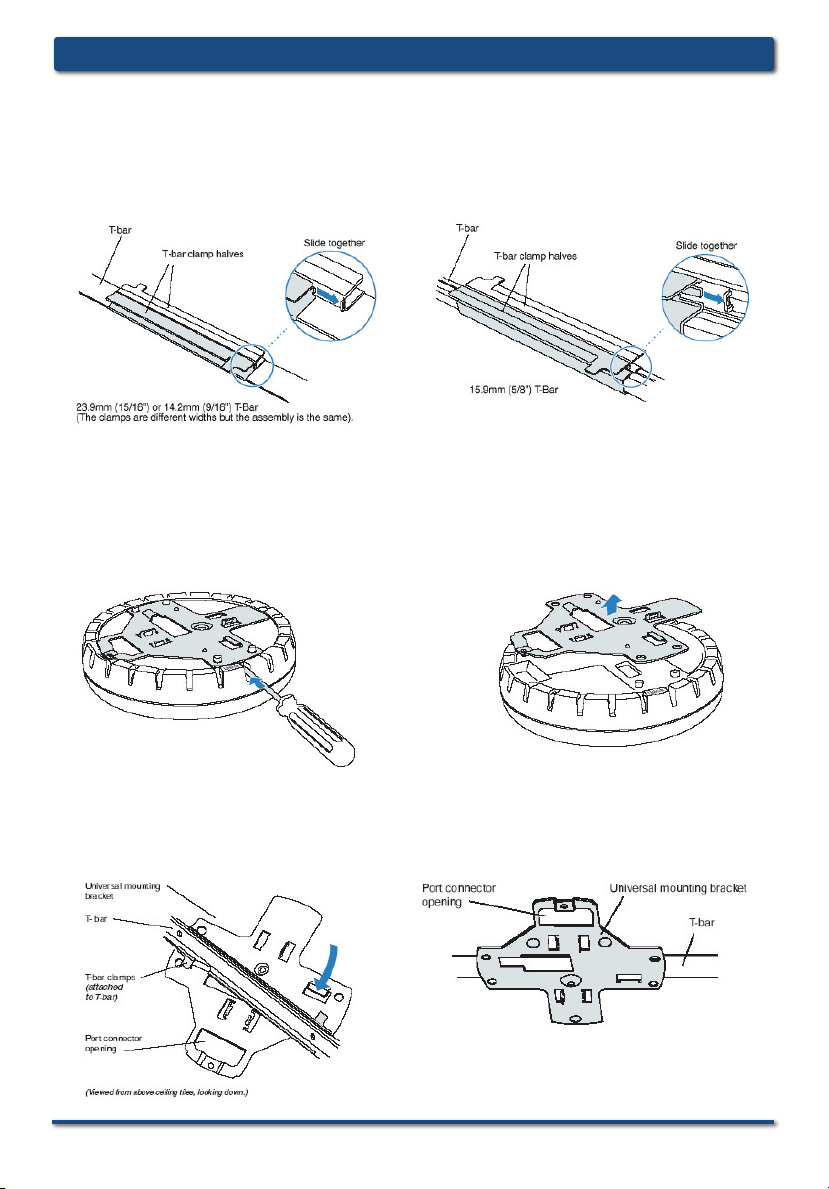
Suspended Ceiling Installation
Drop Ceiling Tiles
This procedure applies to T-bars that are 23.9 mm (15/16 inches),
14.2-mm (9/16-inches), or 15.9-mm (5/8-inches) wide. You also
can use this procedure for flush ceilings with 14.2-mm (9/16-inch)
or 15.9-mm (5/8-inch) T-bars.
1. Use the mounting template to cut a hole for the CAT 5 cable.
D-Link Systems, Inc. 7
Page 8
DWL-8220AP Install GuideInstalling the Hardware
Suspended Ceiling Installation (continued)
2. Install the T-bar clamp that fits the T-bar.
3. Remove the mounting bracket from the DWL-8220AP.
4. Attach the mounting bracket to the T-bar clamp.
8 D-Link Systems, Inc.
Page 9

DWL-8220AP Install Guide Installing the Hardware
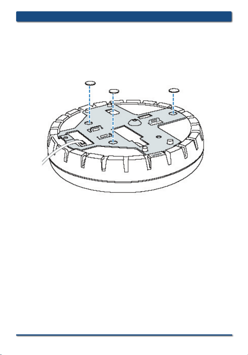
Suspended Ceiling Installation (continued)
5. Insert the CAT 5 cable through the port connector opening in
the mounting bracket, then plug the cable into the DWL-8220AP.
6. Attach the DWL-8220AP to the mounting bracket.
Warning: If you plan to use an external antenna for the
802.11b/g or 802.11a radio, install the antenna at least 20 cm
from the access point.
D-Link Systems, Inc. 9
Page 10

DWL-8220AP Install GuideInstalling the Hardware
Junction Box Installation
1. Remove the mounting bracket from the DWL-8220AP.
2. Attach the bracket to the junction box.
10 D-Link Systems, Inc.
Page 11

DWL-8220AP Install Guide Installing the Hardware
Junction Box Installation (continued)
3. Plug the CAT 5 cable into the access point and attach the
DWL-8220AP to the mounting bracket.
Warning: If you plan to use an external antenna for the
802.11b/g or 802.11a radio, install the antenna at least 20 cm
from the access point.
D-Link Systems, Inc. 11
Page 12

DWL-8220AP Install GuideInstalling the Hardware
Solid Wall or Ceiling Installation
1. Use the mounting template to cut a hole for the CAT 5 cable.
2. Remove the mounting bracket from the DWL-8220AP.
3. Attach the bracket to the wall or ceiling.
12 D-Link Systems, Inc.
Page 13

DWL-8220AP Install Guide Installing the Hardware
Solid Wall or Ceiling Installation (continued)
4. Plug the CAT 5 cable into the access point.
5. Attach the access point to the mounting bracket.
Warning: If you plan to use an external antenna for the
802.11b/g or 802.11a radio, install the antenna at least 20 cm
from the access point.
D-Link Systems, Inc. 13
Page 14

DWL-8220AP Install GuideInstalling the Hardware
Tabletop Installation
1. Remove the mounting bracket from the DWL-8220AP.
2. Reverse the bracket and attach it to the DWL-8220AP.
14 D-Link Systems, Inc.
Page 15
DWL-8220AP Install Guide Installing the Hardware
Tabletop Installation (continued)
3. Attach the rubber feet.
4. Turn the DWL-8220AP over and place it on the table.
Warning: If you plan to use an external antenna for the
802.11b/g or 802.11a radio, install the antenna at least 20 cm
from the access point.
D-Link Systems, Inc. 15
Page 16

DWL-8220AP Install GuideContacting Technical Support
Technical Support
D-Link’s website contains the latest user documentation and software updates
for D-Link products.
D-Link provides free technical support for customers within the United States
and Canada for the duration of the product’s warranty period.
U.S. and Canadian customers can contact D-Link Technical Support through
our website or by phone.
United States
Telephone
(877) 453-5465
Monday through Friday
8:00AM - 5:00PM (Pacific Standard Time)
World Wide Web
http://support.dlink.com
E-mail
support@dlink.com
Canada
Telephone
(800) 361-5265
Monday through Friday, 7:30am to 12:00am EST.
World Wide Web
http://support.dlink.ca
E-mail
support@dlink.ca
Version 1.0
Revised 08/07/2005
©2005 D-Link Systems, Inc. All rights reser ved. Trademarks are the property of their respective holders. Software
and specifications subject to change without notice. Maximum wireless signal rate based on IEEE Standard
802.11a/11b/11g specifications. Actual data throughput will vary. Network conditions and environmental factors,
including volume of network traffic, building materials and construction, and network overhead lower actual data
throughput rate.
16 D-Link Systems, Inc.
 Loading...