

Page 1
D-Link DVG-5121SP
VoIP Telephone Adapter
User Manual
Building Networks for People
RECYCLABLE
2006/11/27
Ver. 1.00
Page 2

Table of Content DVG-5121SP User’s Manual
1. Introduction
1-1. Product Overview..…..................................................................................................5
1-2. Product Features……………………………..……………….……………………………6
1-3. Hardware Description……………………………………………………………………...8
2. Before You Begin
2-1. Package Contents ...................................................................................................11
2-2. System Requirements …….………….………………………………………………….11
3. Installation and Applications
3-1. VoIP Telephone Adapter Assigned with a Public IP Address…………………………12
3-2. VoIP Telephone Adapter in a NAT Network………………………………………….....13
3-3. Telephone Interface Description…………………………………………..…………….14
3-4. Setting a VoIP Telephone Adapter with WEB Browser…………………………..……15
4. Basic Network Settings
4-1. WAN
4-1-1. Static IP………………………………………………………………………………….17
4-1-2. DHCP……………………………………………………………………………………18
4-1-3. PPPoE………………………………………………………………………..………… 20
4-1-4. PPtP………….…………………………………………………………………….…….24
4-1-5. L2TP……….…………………………………………………………………………….27
4-1-6. Big Pond………….……………………………………………………………………..29
4-2. LAN
LAN Setting…………………………………………………………………………….……….31
4-3. DHCP Server
4-3-1. DHCP Server Setting………..…………………………………………………………32
4-3-2. DHCP Static Map…………………………………………………………………….....33
5. Advance Network Settings
5-1. NAT…………………………….…………………………………………………………...34
5-2. Virtual Server Setting……….…………………………………………………………….35
5-3. Application Setting………………………………………………………………………..37
2
D-Link Corporation
Page 3

Table of Content DVG-5121SP User’s Manual
5-4. UPNP Setting……………………………………………………………………………...39
5-5. Route
Static Route………………………………………………………………………………….….40
5-6. Security
5-6-1. MAC filter………………………………………………………………………………..42
5-6-2. IP Filter…………………………………………………………………………………..43
5-6-3. URL Filter………………………………………………………………………………..44
5-6-4. Domain Filter……………………………………………………………………………45
5-6-5. Firewall…………………………………………………………………………………..46
5-6-6. Rule Summary……….………………………………………………………………….47
6. SIP Setting
6-1. Basic Setting………………………………………………………………………………48
6-2. Account Setting………………………………………………………….........................50
6-3. NAT Traversal……………………………………………………………………………..51
7. VOIP Setting
7-1. Voice Setting………………………………………………………………………………52
7-2. Call Service………………………………………………………………………………..54
7-3. Phone Setting……………………………………………………………………………..56
7-4. E.164 Setting……………………………………………………………………………...58
7-5. FAX Setting………………………………………………………………………………..59
7-6. General Dialing Setting……………………………………………………....................60
7-7. QOS/TOS Setting…………………………………………………………………………61
7-8. Phone Book………………………………………………………………………………..64
7-9. Call Screen……………………………………………………...…………………………65
8. Tools
8-1. Admin………………………………………………………………………………………66
8-2. Page Configure…………..……………………………………………………………….67
8-3. Date/Time………………………………………………………………………………….68
8-4. DDNS………………………………………………………………………………………70
8-5. System……………………………………………………………………………………..71
3
D-Link Corporation
Page 4

Table of Content DVG-5121SP User’s Manual
8-6. Firmware…………………………………………………………………………………...72
8-7. Device Setting……………………………………………………………………………..73
9. Status
9-1. Device Information………………………………………………………………………..74
9-2. Log………………………………………………………………………………………….75
9-3. Status……………………………………………………………………………………….76
9-4. CDR………………………………………………………………………………………...77
10. Telnet
Run Telnet……………………………………………………………………………………….78
4
D-Link Corporation
Page 5

Introduction DVG-5121SP User’s Manual
1. Introduction
1-1. Product Overview
D-Link®, an industry leader in networking, introduces DVG-5121SP VoIP telephone adapter for
the h ome envir onment. The DVG-5121SP VoIP Telephone Adapter converts any existin g analog
(cord or cordless) telephone into an IP Phone. Also by plugging in a FAX machine, the
DVG-5121SP will enable users to send and receive fax the same way as a traditional analog
telephone line.
The DVG-5121SP carries both voice and facsimile over the IP network. It supports SIP industry
standard call control protocol and is compatible with free registration services or VoIP service
providers’ systems. It also supports the most popular audio CODECs to ensure compatibility
and voice quality.
The DVG-5121SP provides two FXS port to connect to two analog telephone sets, PSTN lifeline
port to connect to the phone line, one Fast Ethernet (10/100) port to connect to the VoIP
telephone adapter and another LAN port which allow another computer to be connected by wire.
VoIP service providers can con gure service settings such as a server address, CODEC and
STUN s ettings via TF T P directly t o the DVG-5121SP.
For security, all of the con guration settings are encrypted. Only the VoIP service
providers/resellers with the authenticated password and user name can access them.
The DVG-5121SP fe atures both t he VAD (Voice Act ivity Detect ion) and CNG (Comfort Noise
Generator) to reduce the band width consumption and to sustain voice quality.
The DVG-5121SP has a built-in QoS setting to provide voice priority in IP networks and prevent dropped calls.
D-Link Corporation
5
Page 6

Introduction DVG-5121SP User’s Manual
1-2. Product Features
WAN:
One RJ-45 10/100Mbps auto-MDI/MDIX Ethernet port
WAN type: Static IP, PPPoE, DHCP, PPtP, Big Pond, PPtP Client
VPN Pass Through
QoS: IP Precedence, DiffServ
NAT Traversal: Outbound Proxy, STUN, UPnP
SIP and RTP Priority Queuing
RTP Packet Summary: sent, received, loss packet count
NTP: 3 Time Servers, Time Zone support
DDNS: DynDns.ORG
MAC Address Clone
LAN:
One RJ-45 10/100Mbps auto-MDI/MDIX Ethernet port
Router or Bridge mode
NAT / PAT (RFC1631 / RFC3235):
Virtual Server, DMZ
DHCP Server (RFC 2131 / RFC2132)
Firewall: MAC Filter, IP Filter, Port Filter
VoIP:
Two FXS RJ-11 ports
One FXO RJ-11 PSTN life line port
Management:
LEDs: Power/Alarm, VoIP, WAN, LAN, Phone/Line
Web-based, TELNET
Password controlled administration
Remote firmware upgrade via TFTP or FTP
Inbuilt PING tool
Multi-function reset button: restore default
D-Link Corporation
6
Page 7

Introduction DVG-5121SP User’s Manual
Voice
Pond Key
SIPv2 (RFC3261) compliance
SIP METHOD: ACK, BYE, CANCEL, INFO, INVITE, NOTIFY, OPTIONS,
PING, PRACK, REFER, REGISTER, SUBSCRIBE, UPDATE
SIP Extension: Session Timer, Proxy-Require,
P-Asserted (RFC3325), MWI (RFC3842)
Voice Compression: G.711 a/u-law , G.726, G.729A/B, G.723.1
CNG and VAD
Silence suppression & detection
168 Echo Cancellation
Adaptive jitter buffer
Programmable gain control
In-band DTMF
Out-of-band DTMF relay: RFC2833
*DTMF
Termination Impedance: 600/900& complex Impedance
Failover SIP Proxy server registrations
Failsafe Mechanism (FXS relay to PSTN):
Network failure
Service unavailable
Power loss
*T.30 FAX pass through, T.38 real time FAX relay
Caller ID: DTMF, FSK-Bellcore
*Hunting number support
*Telephone book
*E.164 numbering
Hot line
Call features:
Call Hold, Call Waiting, *Call Pickup
Call Forward - Unconditional, Busy, No Answer
*Call Transfer - Unattended, Attended
Speed Dialing, Repeat Dialing, Three Way Calling (Media Server required)
D-Link Corporation
7
Page 8
Introduction DVG-5121SP User’s Manual
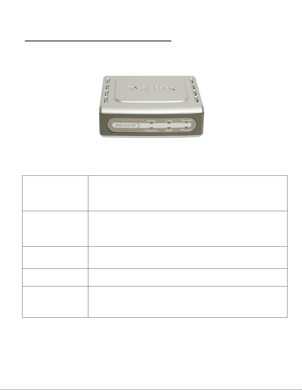
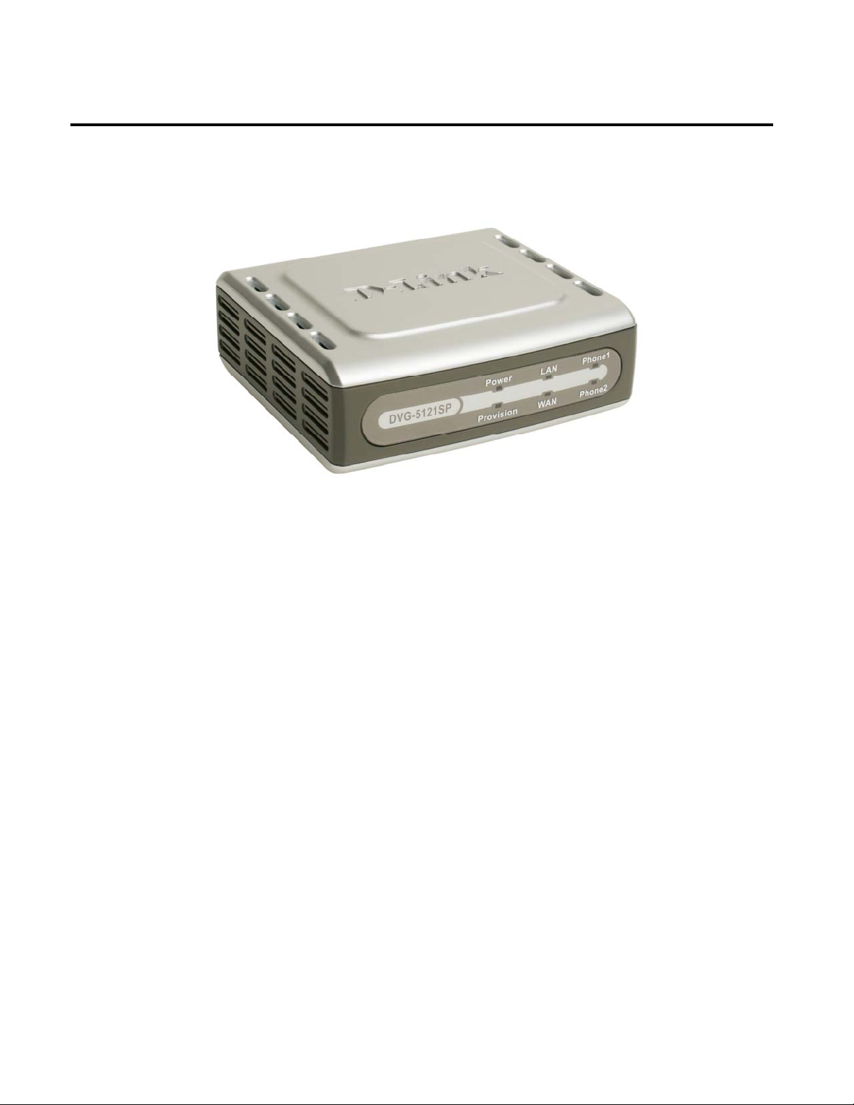
1-3. Diagnostic LEDs and External Interfaces
Front Panel
WAN LED
LAN LED
Power LED
Provision LED
Phone LEDs
Phone 1
Phone 2
When a connection is established, this LED is on. The LED will blink to indicate network
traffic is passing through the WAN port. If the LED does not light up when a cable is
connected, verify the cable connections and make sure the connected devices are
powered on.
When a connection is established, the LED will light up. The LED will blink to indicate
activity. If the LED does not light up when a cable is connected, verify the cable
connections and make sure the connected devices are powered on.
When this LED is on, DVG-5121SP is powered on.
The Provision LED will flash during the device access to TR-069 provision ACS and off
after provision process finished
These LEDs display the VoIP status and Hook activity on the phone ports that are used
to connect to the analog telephones. If a phone connected to a phone port is off hook or
in use, this LED will light up. When a phone is ringing, the indicator will blink.
D-Link Corporation
8
Page 9
Introduction DVG-5121SP User’s Manual
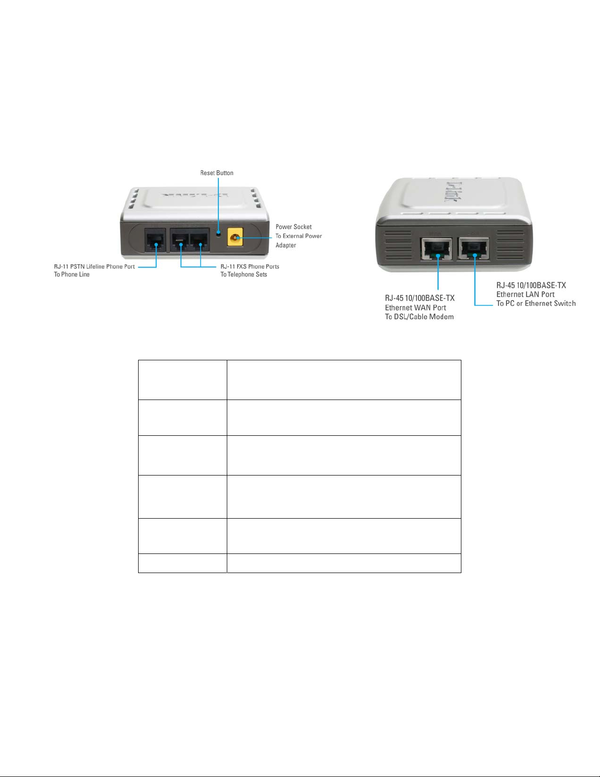
Rear Panel Side Panel
This port connects to your broadband modem or
WAN Port
router through an Ethernet cable.
LAN Port
Reset
Phone Ports
x2
RJ11 PSTN Life
Line Phone Port
Power Socket
This port connect to an Ethernet enabled computer/
IP sharing device using Ethernet cabling.
This button is used to reset the unit to its factory
default settings.
Each of ports connects to an analog phone via an
RJ-11 phone cable.
This port connects to the wall phone line via an
RJ-11 phone cable.
This socket connects to the external power adapter.
D-Link Corporation
9
Page 10

Introduction DVG-5121SP User’s Manual
WARNING: To avoid any possible damage to your DVG-5121SP devices, do not connect the
Phone 2 port to a wall phone line. If any of these are done, your DVG-5121SP may be damaged.
Restore to factory default:
A Reset Button is provided on the rear panel of the DVG-5121SP VoIP Telephone Adapter. This Reset Button is
used to restore any settings that you have act in the DVG-5121SP to its factory default settings. Examples of
these settings are the IP address, user’s name and password.
To reset the DVG-5121SP to its default settings, do as follows:
(1) Turn OFF the power of the DVG-5121SP by unplugging the external power adapter.
(2) Use a tip of a pen, push the Reset Button continuously for about 6 seconds.
(3) Release the Reset Button to return the DVG-5121SP to its default settings
D-Link Corporation
10
Page 11
Before You Begin DVG-5121SP User’s Manual
2. Before You Begin
2-1. Package Contents
Check the Content of Your DVG-5121SP Package
DVG-5121SP VoIP Telephone Adapter
CAT5 Ethernet Cable* 1
CD-ROM
Standard RJ-11 Phone Cable*1
Quick Installation Guide
12VDC 1.25A Power Adapter
If any of the above items are missing, please contact your reseller.
2-2. System Requirements for
Make sure you have all of the following before you begin to set up the DVG-5121SP
A subscription with an Internet Service Provider (ISP)
:
Configuration:
A Computer running Windows, with a CD-ROM drive and an Ethernet port
An Ethernet-based broadband modem
A st andard analog telephone
11 D-Link Corporation
Page 12

Installation and Applications DVG-5121SP User’s Manual
3. Installation and Applications
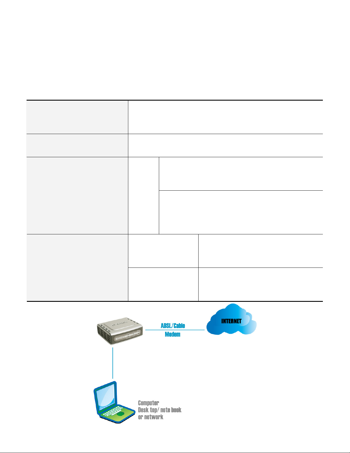
3-1. VoIP Telephone Adapter Assigned with a Public IP Address
The VoIP telephone adapter will have a Public IP address for Internet connection regardless of whether it is a
static IP address, DHCP (using a Cable Modem), or PPPoE (Dialup / ADSL).
VoIP telephone adapter IP
Settings
NAT/STUN Settings Optional setting
DDNS Settings Optional setting
Need to set up as static IP,
DHCP, or PPPoE
12 D-Link Corporation
Page 13
Installation and Applications DVG-5121SP User’s Manual
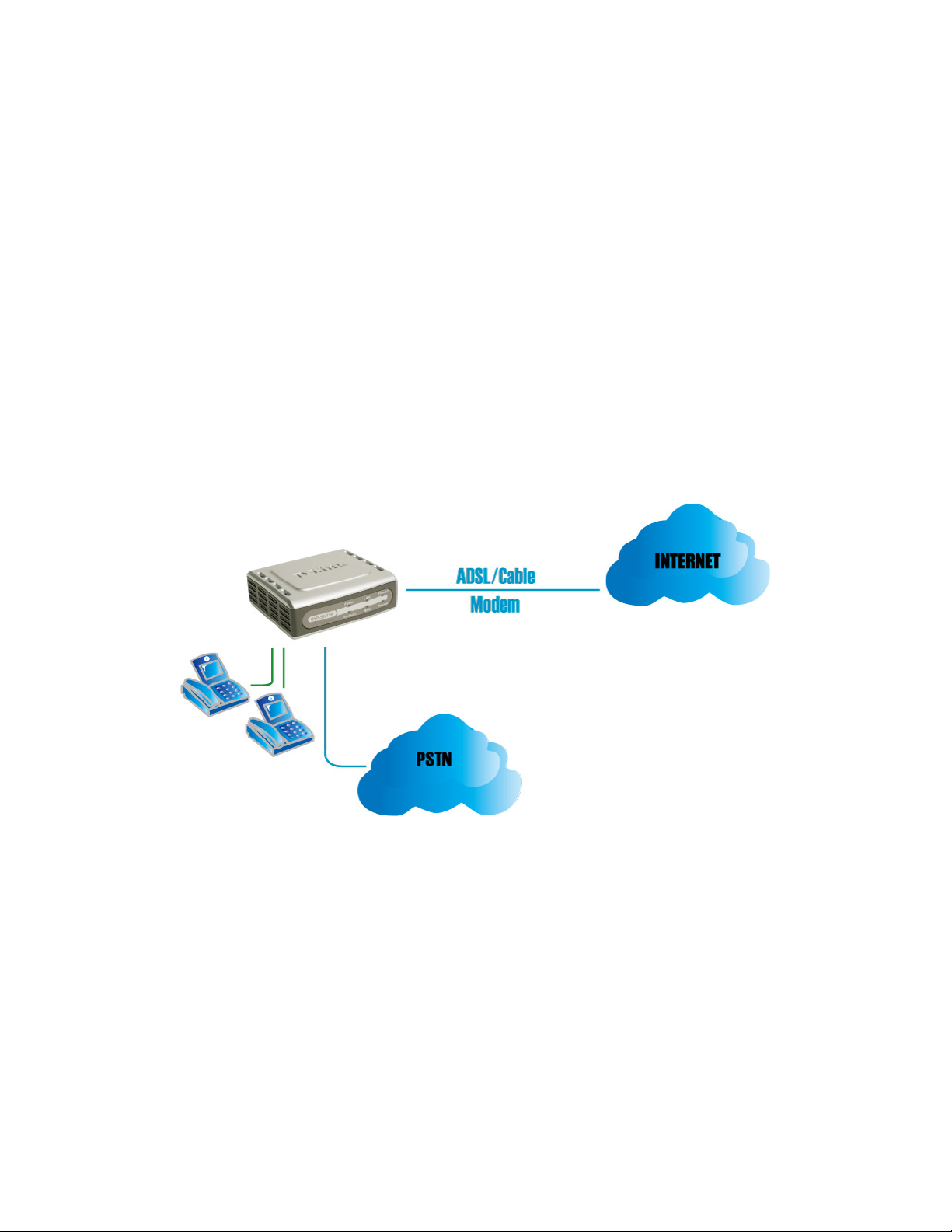
3-2. VoIP telephone adapter in a NAT network
The VoIP telephone adapter uses a virtual IP address and the IP sharing function of other systems to connect
to the Internet.
LAN IP address of IP sharing Please avoid IP address 192.168.1.1-192.168.1.254 (You may need to
change the settings of IP sharing or change SIP series VoIP telephone
adapter LAN Port IP address)
VoIP telephone adapter IP Settings Set as static IP address, and assign the LAN IP address of the IP sharing to
the Default VoIP telephone adapter.
NAT /STUN Settings
Enable
The WAN of the IP sharing
device has a static IP
address.
The WAN of the IP sharing
device has a dynamic IP
address.
If the WAN of the IP sharing device has static IP address, then
the NAT IP address is set as the Public IP address of the IP
sharing.
If the WAN of the IP sharing device uses a dynamic IP address,
then it has to comply with the DDNS settings. When suing NAT,
you must enter the URL (Uniform Resource Locator) that is
registered to the DDNS server.
Disabled DDNS Settings
Enabled: enter the registered URL (Uniform
Resource Locator) into the network settings ->
under NAT
13 D-Link Corporation
Page 14
Installation and Applications DVG-5121SP User’s Manual
3-3. Telephone Interface Description
Example:
DVG-5121SP connecting directly to phone sets
After connecting telephone sets to P1-P2, users can make direct calls, (P1-P2 are FXS interfaces). Each set
acts as an independent IP line that provided by applied SIP server.
Integrating the DVG-5121SP with PBX
Line port is PSTN/ PBX <FXO> interfaces, that connected to telephone sets for direct calls. But for this product
definition, it just supported as a back up solution enabled automatically when network or SIP phone failed.
14 D-Link Corporation
Page 15
Installation and Applications DVG-5121SP User’s Manual
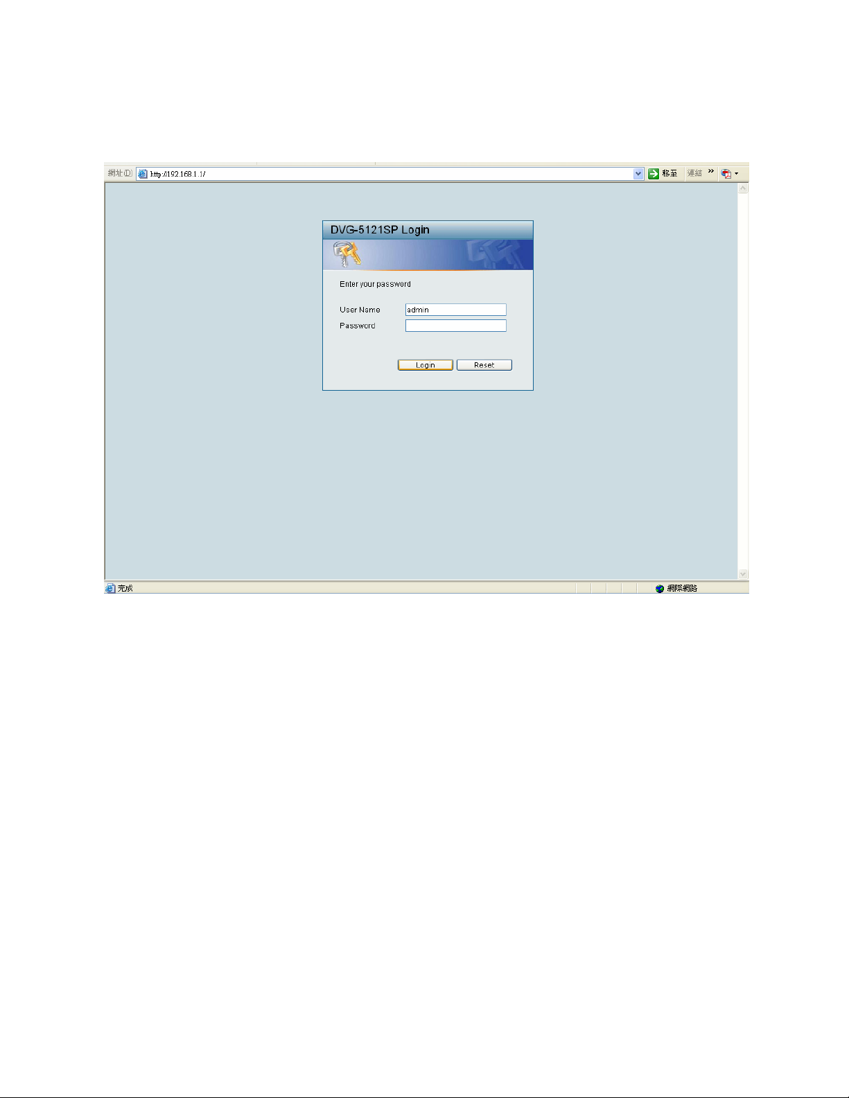
3-4. Setting up the DVG-5121SP Using a Web Browser
The factory default LAN Port IP address is 192.168.1.1
Instructions
Step1. Open an Internet browser.
Step2. Enter VoIP telephone adapter’s WAN Port IP address in the website address area (If the PC is
connected to the LAN Port, enter the LAN Port IP address. The default is 192.168.1.1)
Step3. The factory default settings for Login ID is Admin and Password is left blank).
Step4. Change the default settings of Administrator’s Name, Password and Web UI Login ID, Password in
Administrator account.
After completing and confirming the settings, some of the settings will take effect immediately. But some
of network related settings would take effect after the VoIP telephone adapter is restarted. Please go to
System Operation to save the settings before restarting the system if needed.
15 D-Link Corporation
Page 16

Installation and Applications DVG-5121SP User’s Manual
The DVG-5121SP VoIP telephone adapter doesn’t allow multiple people to configure the VoIP
telephoneadapter at the same time. If a user already logged into the system, other users from different
IP addresses cannot login at the same time. Please remember to logout or restart the system if not
using the web configuration function. Or some of the network management, like the Telnet will not be
allowedto use for the network control.
16 D-Link Corporation
Page 17
Basic Network Settings DVG-5121SP User’s Manual
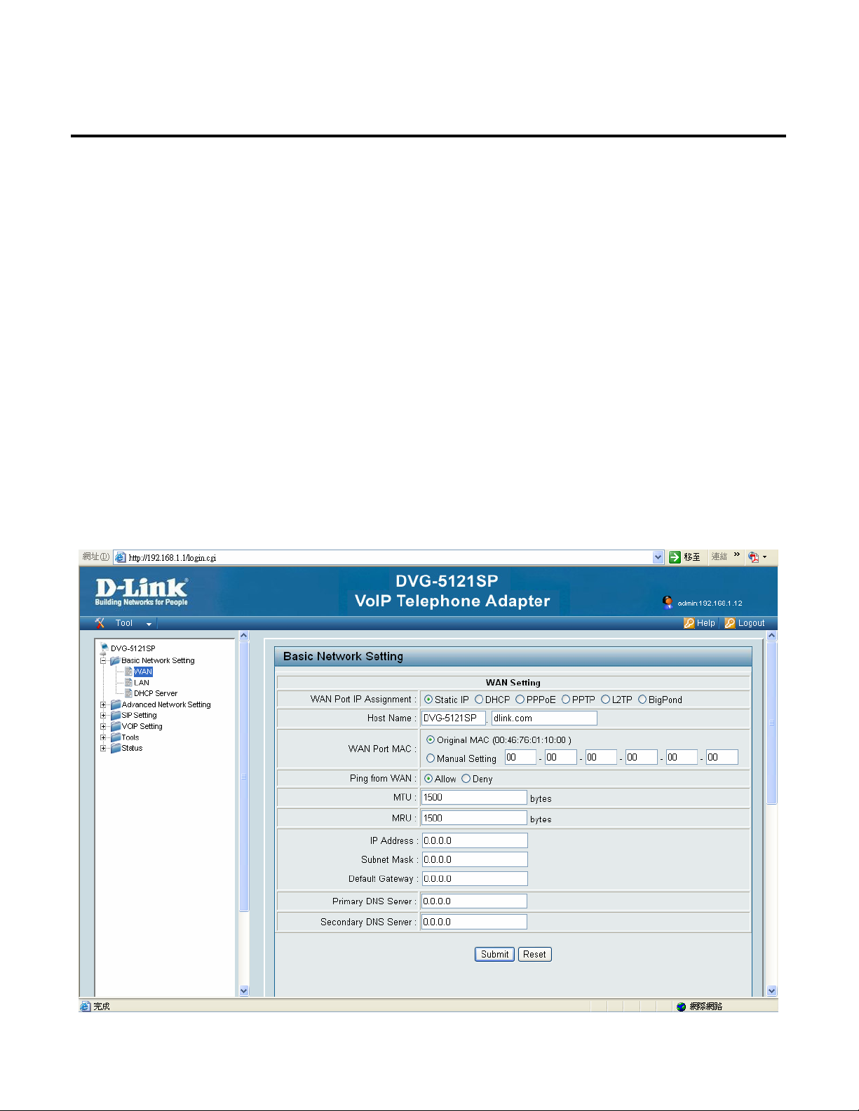
4. Basic Network Settings
4-1. WAN
The network settings are used to set the VoIP telephone adapter’s communication ports, IP configurations,
ADSL service setting, IP tunneling and etc. You might refer to the following pages for different WAN settings.
4-1-1. Static IP
Just as each building on a street has an address, so does each computer on the Internet. This "address
scheme" allows you to distinguish between every computer on the Internet. For example, you may have come
across a number in association with Internet lingo such as "198.69.121.3"--or something similar. This is an
Internet Protocol (IP) address.
WAN Port IP Assignment: Select Static if your ISP assigned you a fixed IP address, subnet mask, and DNS server
addresses. Please contact your local Internet Service Provider (ISP) if you have any questions.
17
D-Link Corporation
Page 18
Basic Network Settings DVG-5121SP User’s Manual
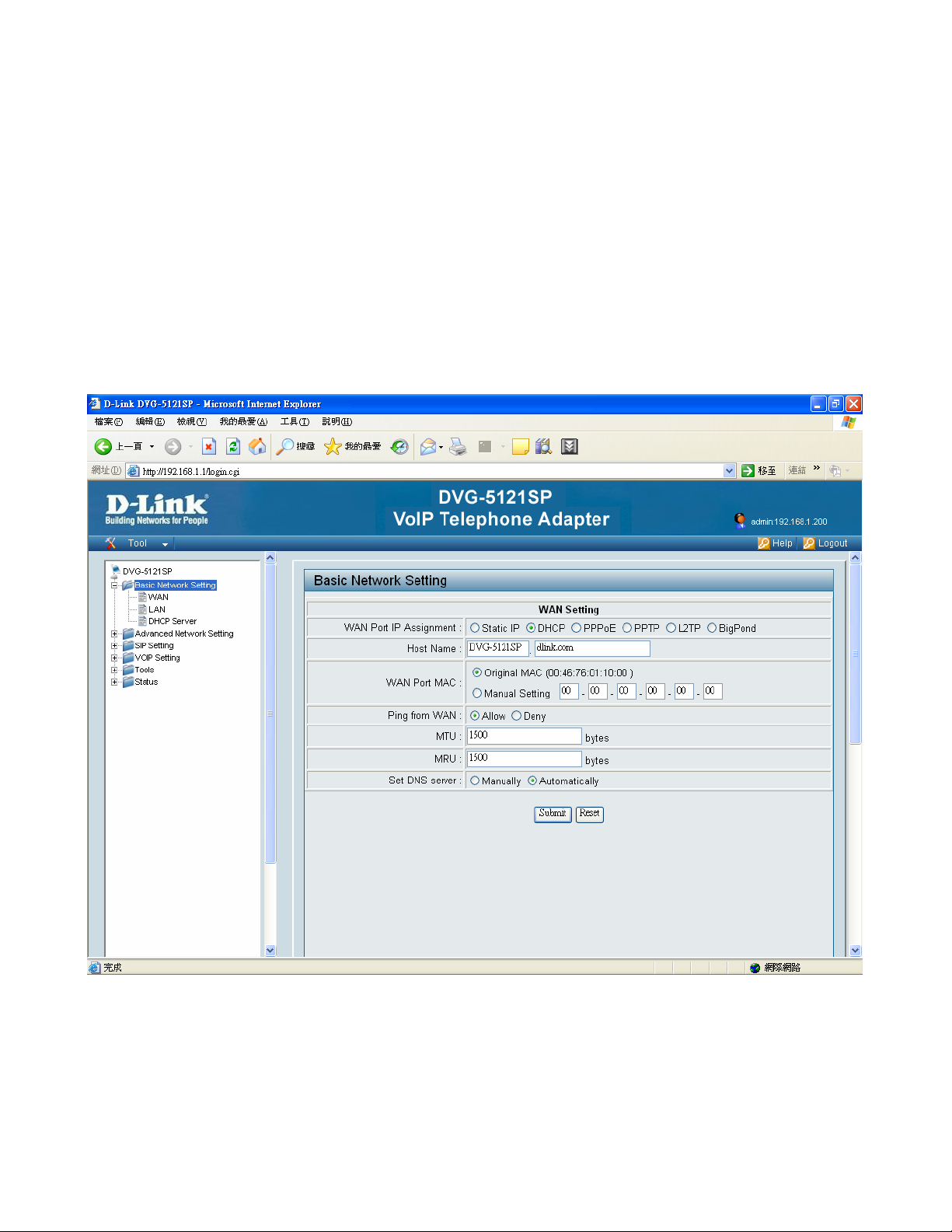
4-1-2. DHCP
DHCP stands for "Dynamic Host Configuration Protocol". DHCP's purpose is to enable individual computers on an IP network to
extract their configurations from a server (the 'DHCP server') or servers, in particular, servers that have no exact information
about the individual computers until they request the information. The overall purpose of this is to reduce the work necessary to
administer a large IP network. The most significant piece of information distributed in this manner is the IP address.
WAN Port IP Assignment: Select Dynamic (DHCP, most common) to set user settings of WAN port MAC, WAN
port ping and DNS server
Host Name: The Host Name is optional but may be required by some ISPs. The default host name is the
device name of the Router and may be changed.
18
D-Link Corporation
Page 19

Basic Network Settings DVG-5121SP User’s Manual
WAN Port MAC: The default MAC Address is set to the WAN’s physical interface MAC address on the VoIP
telephone adapter. It is not recommended that you change the default MAC address unless required by your
ISP. The default MAC address is set to the WAN’s physical interface MAC address on the VoIP telephone
adapter. You can use the “Clone MAC Address” button to copy the MAC address of the Ethernet Card installed
by your ISP and replace the WAN MAC address with the MAC address of the router.
Ping from WAN: While enable, it allows end user ping from WAN through internal to check the device working
or not.
MTU: Maximum Transmission Unit - you may need to change the MTU for optimal performance with your
specific ISP. 1500 bytes is the default MTU.
MRU: Maximum Receive Unit - you may need to change the MRU for optimal performance with your specific
ISP. 1500 is the default MRU.
Set DNS server: Enter the Primary DNS server IP address assigned by your ISP.
19
D-Link Corporation
Page 20
Basic Network Settings DVG-5121SP User’s Manual
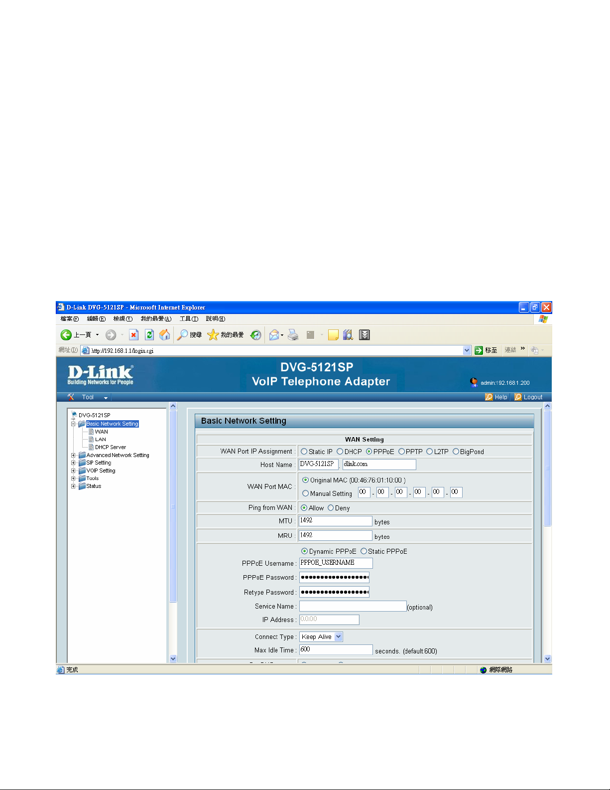
4-1-3. PPPoE (DSL)
Point to Point Protocol over Ethernet is a proposal specifying how a host personal computer (PC) interacts with
a broadband modem (i.e. xDSL, cable, wireless, etc) to achieve access to the growing number of High speed
data networks. Relying on two widely accepted standards, Ethernet and the point-to-point protocol (PPP), the
PPPoE implementation requires virtually no more knowledge on the part of the end user other than that required
for standard Dial up Internet access. In addition, PPPoE requires no major changes in the operational model for
Internet Service Providers (ISPs) and carriers. The significance of PPP over Ethernet has to do with its far
greater ease of use versus competing approaches. By making high speed access easier to use for end
consumers, and more seamless to integrate into the existing infrastructure for carriers and ISPs, PPPoE could
speed the widespread adoption of High speed access services
WAN Port IP Assignment: Select PPPoE.
Host Name: The Host Name is optional but may be required by some ISPs. The default host name is the
device name of the Router and may be changed.
20
D-Link Corporation
Page 21

Basic Network Settings DVG-5121SP User’s Manual
WAN Port MAC: The default MAC Address is set to the WAN’s physical interface MAC address on the VoIP
telephone adapter. It is not recommended that you change the default MAC address unless required by your
ISP. The default MAC address is set to the WAN’s physical interface MAC address on the VoIP telephone
adapter. You can use the “Clone MAC Address” button to copy the MAC address of the Ethernet Card installed
by your ISP and replace the WAN MAC address with the MAC address of the router.
Ping from WAN: While enable, it allows end user ping from WAN through internal to check the device working
or not.
MTU: Maximum Transmission Unit - you may need to change the MTU for optimal performance with your
specific ISP. 1500 is the default MTU.
MRU: Maximum Receive Unit - you may need to change the MRU for optimal performance with your specific
ISP. 1500 is the default MRU.
PPPoE Username: Enter your PPPoE user name.
PPPoE Password: Enter your PPPoE password and then retype the password in the next box.
Service Name: Enter the ISP Service Name (optional).
IP Address: Enter the IP address (Static PPPoE only).
Connect Type: Select either Keep Alive or Manual on.
Max Idle Time: Enter a maximum idle time during which the Internet connection is maintained during inactivity.
To disable this feature, enable Auto-reconnect.
Set DNS server: Enter the Primary and Secondary DNS Server Addresses (Static PPPoE only).
21
D-Link Corporation
Page 22
Basic Network Settings DVG-5121SP User’s Manual
yp
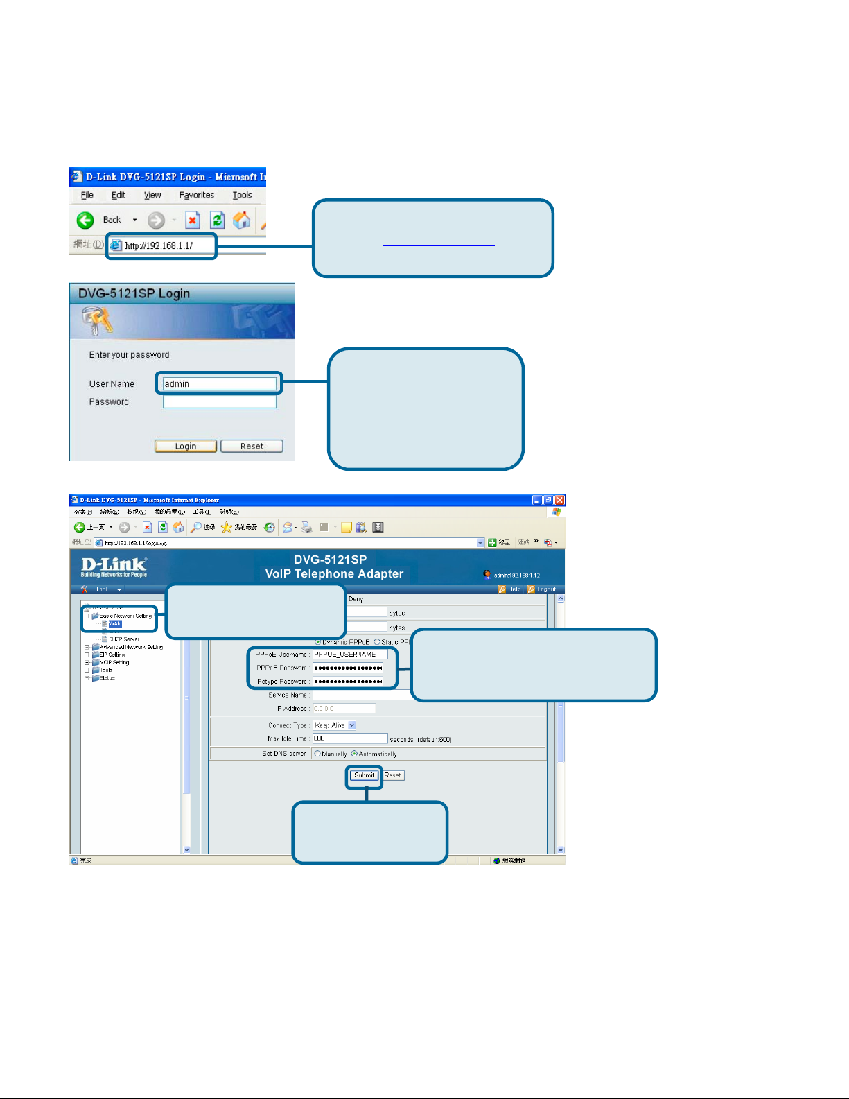
Open your web browser and enter
the URL
address bar and press Enter.
http://192.168.1.1 in the
Enter “admin” as the
username and click Login
to enter the device’s Web
GUI. No password
needed.
Click Basic Network
Settings and then WAN.
Click the PPPoE radio button.
Enter PPPoE Username,
Password and Ret
Click Submit at the
bottom of the page.
e Password.
22
D-Link Corporation
Page 23
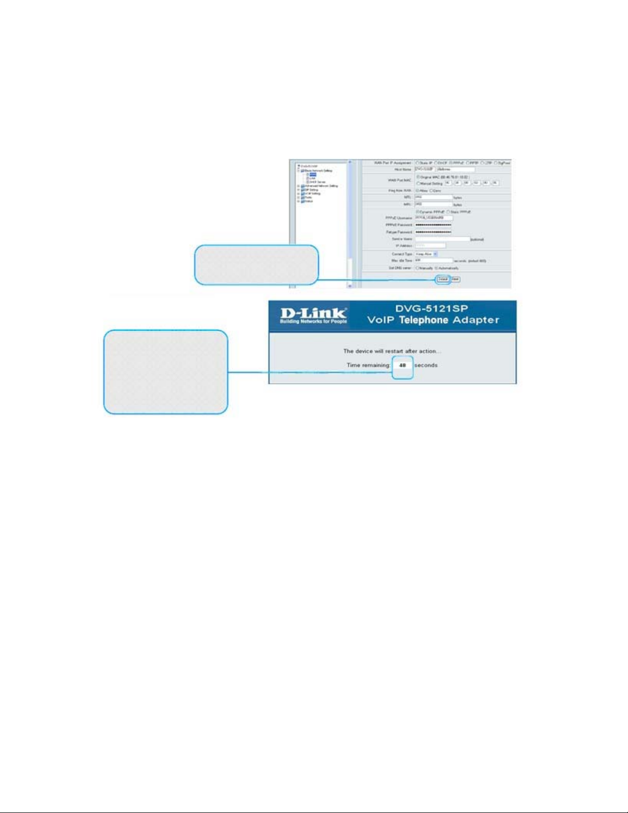
Basic Network Settings DVG-5121SP User’s Manual
The system will restart after you
click Submit.. After restarting,
the Web GUI will return to the
login page, and the PPPoE
settings you entered will be
displayed after
Click Submit at the bottom of
the page.
23
D-Link Corporation
Page 24
Basic Network Settings DVG-5121SP User’s Manual
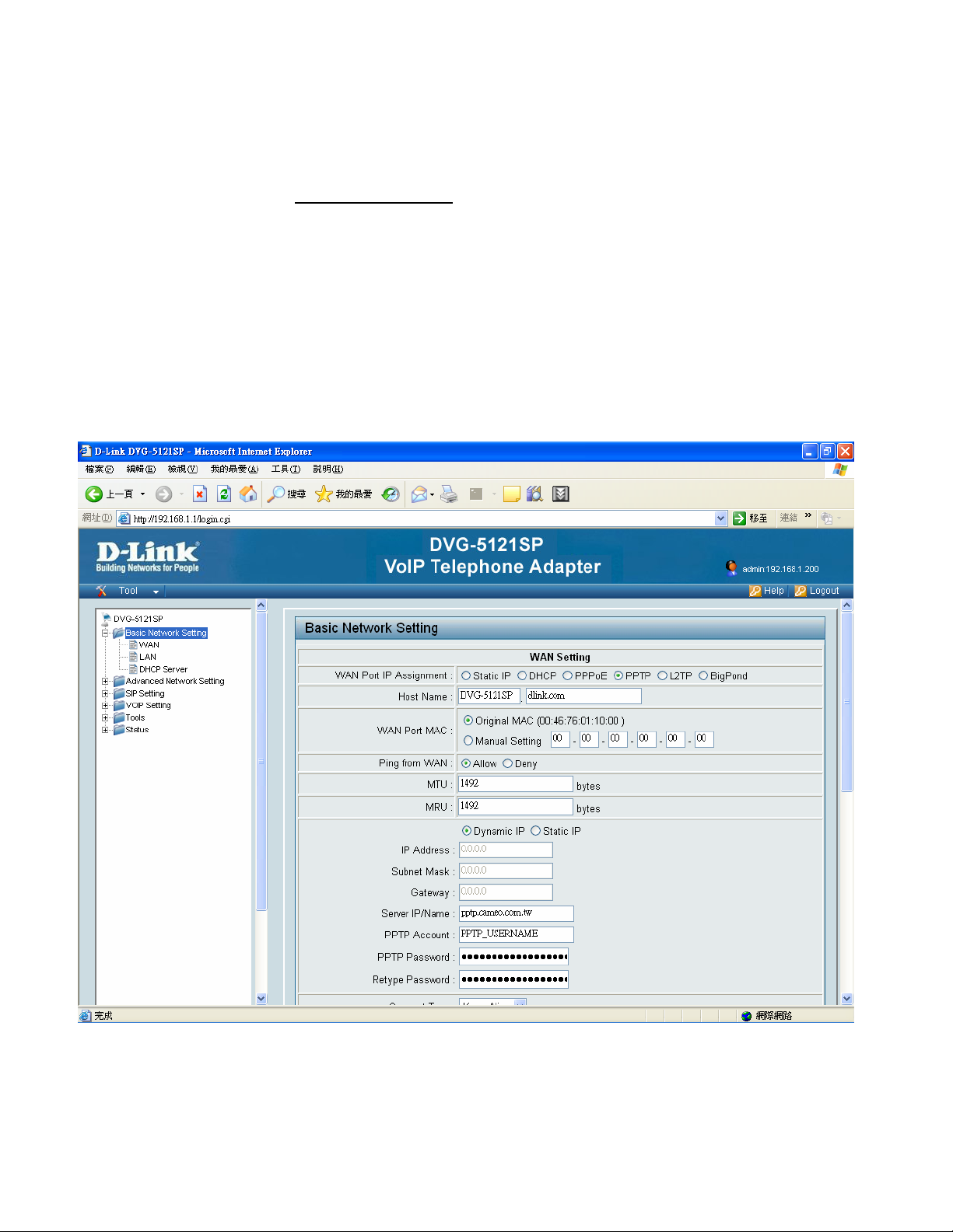
4-1-4. PPTP
PPTP stands for Point to Point Tunneling Protocol. It was developed by a consortium including Microsoft and is
used for establishing VPN (Virtual Private Network) tunnels across the Internet. This allows remote users to
securely and inexpensively access their corporate network from anywhere on the Internet.
PPTP uses a client-server model for establishing VPN connections. Most Microsoft operating systems ship with
a PPTP client, so there is no need to purchase third-party client software. PPTP has the additional advantage
over other VPN technologies of being easy to setup.
WAN Port IP Assignment: Select PPTP.
Host Name: The Host Name is optional but may be required by some ISPs. The default host name is the device
name of the Router and may be changed.
24
D-Link Corporation
Page 25

Basic Network Settings DVG-5121SP User’s Manual
WAN Port MAC: The default MAC Address is set to the WAN’s physical interface MAC address on the VoIP
telephone adapter. It is not recommended that you change the default MAC address unless
required by your ISP. The default MAC address is set to the WAN’s physical interface MAC
address on the VoIP telephone adapter. You can use the “Clone MAC Address” button to copy the
MAC address of the Ethernet Card installed by your ISP and replace the WAN MAC address with
the MAC address of the router.
Ping from WAN: While enable, it allows end user ping from WAN through internal to check the device working or
not.
MTU: Maximum Transmission Unit - you may need to change the MTU for optimal performance with your specific
ISP. 1500 is the default MTU.
MRU: Maximum Receive Unit - you may need to change the MRU for optimal performance with your specific ISP.
1500 is the default MRU.
IP Address: Enter the IP address (Static PPTP only).
Subnet Mask: Enter the Primary and Secondary DNS Server Addresses (Static PPTP only).
VoIP telephone adapter: Enter the VoIP telephone adapter IP Address provided by your ISP.
Server IP/Name: Enter the Server IP provided by your ISP (optional).
PPTP Account: Enter your PPTP account name.
PPTP Password: Enter your PPTP password and then retype the password in the next box.
Connect Type: Select either Keep Alive or Manual on.
25
D-Link Corporation
Page 26

Basic Network Settings DVG-5121SP User’s Manual
Max Idle Time: Enter a maximum idle time during which the Internet connection is maintained during inactivity. To
disable this feature, enable Auto-reconnect.
Set DNS server: Enter the Primary and Secondary DNS Server Addresses.
26
D-Link Corporation
Page 27

Basic Network Settings DVG-5121SP User’s Manual
4-1-5. L2TP
Layer Two Tunneling Protocol (L2TP) is an extension of the Point-to-Point Tunneling Protocol (PPTP) used by
an Internet service provider (ISP) to enable the operation of a virtual private network (VPN) over the Internet.
WAN Port IP Assignment: Select L2TP.
Host Name: The Host Name is optional but may be required by some ISPs. The default host name is the device
name of the Router and may be changed.
WAN Port MAC: The default MAC Address is set to the WAN’s physical interface MAC address on the VoIP
telephone adapter. It is not recommended that you change the default MAC address unless
27
D-Link Corporation
Page 28

Basic Network Settings DVG-5121SP User’s Manual
required by your ISP. The default MAC address is set to the WAN’s physical interface MAC
address on the VoIP telephone adapter. You can use the “Clone MAC Address” button to copy the
MAC address of the Ethernet Card installed by your ISP and replace the WAN MAC address with
the MAC address of the router.
Ping from WAN: While enable, it allows end user ping from WAN through internal to check the device working or
not.
MTU: Maximum Transmission Unit - you may need to change the MTU for optimal performance with your specific
ISP. 1492 is the default MTU.
IP Address: Enter the IP address (Static L2TP only).
Subnet Mask: Enter the Primary and Secondary DNS Server Addresses (Static L2TP only).
VoIP telephone adapter: Enter the VoIP telephone adapter IP Address provided by your ISP.
Server IP/Name: Enter the Server IP provided by your ISP (optional).
L2TP Account: Enter your L2TP account name.
L2TP Password: Enter your L2TP password and then retype the password in the next box.
Connect Type: Select either Keep Alive or Manual on.
Max Idle Time: Enter a maximum idle time during which the Internet connection is maintained during inactivity. To
disable this feature, enable Auto-reconnect.
Set DNS server: The DNS server information will be supplied by your ISP (Internet Service Provider.)
28
D-Link Corporation
Page 29

Basic Network Settings DVG-5121SP User’s Manual
4-1-6. Big Pond
This service is supported in Australia only.
WAN Port IP Assignment: Big Pond.
Host Name: The Host Name is optional but may be required by some ISPs. The default host name is the device
name of the Router and may be changed.
WAN Port MAC: The default MAC Address is set to the WAN’s physical interface MAC address on the VoIP
telephone adapter. It is not recommended that you change the default MAC address unless
required by your ISP. The default MAC address is set to the WAN’s physical interface MAC
address on the VoIP telephone adapter. You can use the “Clone MAC Address” button to copy the
29
D-Link Corporation
Page 30

Basic Network Settings DVG-5121SP User’s Manual
MAC address of the Ethernet Card installed by your ISP and replace the WAN MAC address with
the MAC address of the router.
Ping from WAN: While enable, it allows end user ping from WAN through internal to check the device working or
not.
BigPond Account: Enter your Big Pond user name.
BigPond Password: Enter your Big Pond password and then retype the password in the next box.
Auth Server: Enter the IP address of the login server.
Server IP/Name: Enter the IP address of the login server.
30
D-Link Corporation
Page 31

Basic Network Settings DVG-5121SP User’s Manual
4-2. LAN
LAN setting
This section will allow you to change the local network settings of the router and to configure the DHCP settings.
LAN IP Address: Enter the IP address of the router. The default IP address is 192.168.1.1.If you change the IP
address, once you click Apply, you will need to enter the new IP address in your browser to get
back into the configuration.
Subnet Mask: Enter the Subnet Mask. The default subnet mask is 255.255.255.0.
DNS Proxy: Check the box to transfer the DNS server information from your ISP to your computers. If unchecked,
your computers will use the router for a DNS server.
31
D-Link Corporation
Page 32

Basic Network Settings DVG-5121SP User’s Manual
4-3. DHCP Server
4-3-1. DHCP Server setting
stands for Dynamic Host Control Protocol. The DVG-5121SP has a built-in DHCP server.
The DHCP Server will automatically assign an IP address to the computers on the LAN/
private network. Be sure to set your computers to be DHCP clients by setting their TCP/
IP settings to “Obtain an IP Address Automatically.” When you turn your computers on,
they will automatically load the proper TCP/IP settings provided by the DVG-5121SP. The
DHCP Server will automatically allocate an unused IP address from the IP address pool
to the requesting computer. You must specify the starting and ending address of the IP
address pool.
DHCP Server- Select Enabled or Disabled. The default setting is Enabled.
32
D-Link Corporation
Page 33

Basic Network Settings DVG-5121SP User’s Manual
Assigned DHCP IP Address- Set the starting IP address and the ending IP address for the DHCP server’s IP
assignment
Lease Time- The length of time for the IP lease. Enter the Lease time. The
default setting is one hour
4-3-2. DHCP static Map
DHCP Static Map- Select Enabled or Disabled. The default setting is Disable.
IP- Enter the IP address of the client.
MAC- Enter the MAC address of the client.
Description- Enter any description if user wants to separate from other client
33
D-Link Corporation
Page 34

Advance Network Settings DVG-5121SP User’s Manual
5. Advance Network Settings
5-1. NAT
NAT Setting
NAT Setting- User can choose what kind of NAT type need to support in this page.
D-Link Corporation
34
Page 35

Advance Network Settings DVG-5121SP User’s Manual
5-2. Virtual Server Setting
Virtual Server- Select Enabled or Disabled
Name- Enter the name referencing the virtual service
Private IP- The server computer in the LAN (Local Area Network) that will be providing the virtual services.
Protocol Type- The protocol used for the virtual service
Public Port- The port number on the WAN (Wide Area Network) side will be used to access the virtual service.
Private Port- The port number of the service used by the Private IP computer
D-Link Corporation
35
Page 36

Advance Network Settings DVG-5121SP User’s Manual
Schedule-
The schedule of time when the virtual service will be enabled. The schedule may be set to Always,
which will allow the particular service to always be enabled. If it is set to Time, select the time frame for
the service to be enabled. If the system time is outside of the scheduled time, the service will be
disabled.
Example #1:
If you have a Web server that you wanted Internet users to access at all times, you would need to enable it. Web
(HTTP) server is on LAN (Local Area Network) computer 192.168.0.25. HTTP uses port 80, TCP.
Name: Web Server
Private IP: 192.168.0.25
Protocol Type: TCP
Private Port: 80
Public Port: 80
Schedule: always
D-Link Corporation
36
Page 37

Advance Network Settings DVG-5121SP User’s Manual
5-3. Application Setting
Some applications require multiple connections, such as Internet gaming, video conferencing, Internet telephony
and others. These applications have difficulties working through NAT (Network Address Translation). Special
Applications makes some of these applications work with the DVG-5121SP. If you need to run applications that
require multiple connections, specify the port normally associated with an application in the “Trigger Port” field,
select the protocol type as TCP or UDP, then enter the public ports associated with the trigger port to open them for
inbound traffic. The DVG-5121SP provides some predefined applications in the table on the bottom of the web page.
Select the application you want to use and enable it.
Note! Only one PC can use each Special Application tunnel.
Name: This is the name referencing the special application.
D-Link Corporation
37
Page 38

Advance Network Settings DVG-5121SP User’s Manual
Trigger Port:
This is the port used to trigger the application. It can be either a single port or a range of ports.
Trigger Type: This is the protocol used to trigger the special application.
Public Port: This is the port number on the WAN side that will be used to access the application. You may define a
single port or a range of ports. You can use a comma to add multiple ports or port ranges.
Public Type: This is the protocol used for the special application.
D-Link Corporation
38
Page 39

Advance Network Settings DVG-5121SP User’s Manual
5-4. UPNP Setting
Choose UPNP function status.
UPNP
use the Universal Plug and Play feature click on Enabled. UPNP provides compatibility with networking equipment,
software and peripherals of the over 400 vendors that cooperate in the Plug and Play forum.
D-Link Corporation
39
Page 40

Advance Network Settings DVG-5121SP User’s Manual
5-5. Route
Static Route
If the WAN of the IP sharing device has static IP address, then the NAT IP address is set as the Public IP address of
the IP sharing.
Static Route- Select Enabled or Disabled
Type- Choose net or host to do the settings
Target- Input the public IP Address provided by ISP or server
Subnet Mask- Input your Subnet mask. (All devices in the network must have the same subnet mask.)
VoIP telephone adapter: Enter the VoIP telephone adapter IP Address provided by your ISP.
D-Link Corporation
40
Page 41

Advance Network Settings DVG-5121SP User’s Manual
5-6. Security
5-6-1. MAC filter
Use MAC (Media Access Control) Filters to allow or deny LAN (Local Area Network) computers by their MAC
addresses from accessing the Network. You can either manually add a MAC address or select the MAC address
from the list of clients that are currently connected to the Broadband Router.
MAC Filters- Choose Disable MAC filters; allow MAC addresses listed below; or deny MAC addresses listed
below.
MAC Address-
Enter the MAC Address.
Schedule- Select Always or enter the Time Range.
D-Link Corporation
41
Page 42

Advance Network Settings DVG-5121SP User’s Manual
5-6-2. IP Filter
Filters are used to deny or allow LAN (Local Area Network) computers from accessing the Internet. The
DVG-5121SP can be setup to deny internal computers by their IP or MAC addresses. The DVG-5121SP can also
block users from accessing restricted web sites. This is the schedule of time when the IP Filter will be enabled.
IP Filters-
numbers or all ports for the specific IP address.
IP- The IP address of the LAN computer will be denied access to the Internet.
Port- The single port or port range that will be denied access to the Internet.
Use IP Filters to deny LAN IP addresses from accessing the Internet. You can deny specific port
Protocol Type- Select the protocol type
Schedule- This is the schedule of time when the IP Filter will be enabled.
D-Link Corporation
42
Page 43

Advance Network Settings DVG-5121SP User’s Manual
5-6-3. URL Filter
URL Filter- Select Enabled or Disabled.
Fill up with the start IP you would like to allow/deny.
D-Link Corporation
43
Page 44

Advance Network Settings DVG-5121SP User’s Manual
5-6-4. Domain Filter
Domain filter- Select Enabled or Disabled.
Fill up with the IP range you would like to allow/deny.
D-Link Corporation
44
Page 45

Advance Network Settings DVG-5121SP User’s Manual
5-6-5. Firewall
Firewall- Select Enabled or Disabled.
Active- Select Yes or No
Action- Select Allow or Deny
Source- Choose WAN or LAN as the Source and enter a range of IP Addresses out on the internet that you would
like this rule applied to. enter the IP Address of the computer on your local network that you want to allow
the incoming service to. This will not work with a range of IP Addresses
Destination- Select LAN or WAN as the Destination and enter the IP Address of the computer on your local
D-Link Corporation
45
.
Page 46

Advance Network Settings DVG-5121SP User’s Manual
network that you want to allow the incoming service to. This will not work with a range of IP Addresses
Enter the port or range of ports that are required to be open for the incoming service.
Schedule- This is the schedule of time when the IP Filter will be enabled.
.
D-Link Corporation
46
Page 47

Advance Network Settings DVG-5121SP User’s Manual
5-6-6. Rule Summary
Check all security setting rule summary in this page.
D-Link Corporation
47
Page 48

SIP Setting DVG-5121SP User’s Manual
6. SIP Setting
6-1. Basic Setting:
SIP Port Number - also called an outbound proxy, handles SIP call signaling as a standard SIP proxy server. It
receives and transmits phone conversation traffic (media) in between two talking VoIP
telephone adapters. This option tells the VoIP telephone adapter to send and receive all SIP
packets to the destined outbound proxy server rather than the remote VoIP telephone adapter.
This helps VoIP calls to pass through any NAT protected network without additional settings or
techniques. Please make sure your VoIP service provider supports outbound proxy services
before enable it. Default setting: 5060
D-Link Corporation
48
Page 49

SIP Setting DVG-5121SP User’s Manual
Session Timer- It is to avoid the billing of abnormal dropping the call because of Internet. The default is disabled.
Default: 1800 seconds
Media Port Start- Type the beginning of the listening port range
Media Port End- Type the end of the listening port range
RTCP Port- is mainly used to feed the streaming server with reception statistics from the client. The server may then
decide to use these statistics (such as the numbers of lost packets, the delay from reception, ) to adapt
its strategy. Default : 5060
Transport- Choose UDP or TCP
SIP Time Interval- Enter the desired time interval which the VoIP telephone adapter will report to Proxy Server
SIP refresh time- Enter the desired refresh time which the VoIP telephone adapter will refresh status to Proxy
Server. Default: 500
Timeout for Invite- Time for server invite the clients to connect. Default: 12
Timeout for Release- Set the VoIP telephone adapter respond releasing time from server. Default: 4
Regisitration Retry Count- Retry Count timing. Default: 65535
Registration Retry Interval- Time between per retry connection. Default: 30
PING Interval- Time between ping packet. Default: 0
SIP User Agent Name- Default: VOIP_Agent_001
D-Link Corporation
49
Page 50

SIP Setting DVG-5121SP User’s Manual
6-2. Account Setting:
Authentication Expired Time- Time for authentication expired. Default: 3600 seconds
Invite with ID / Account- DVG-5121SP can be invited to a VoIP trunk VoIP telephone adapter w/o register to a
Proxy. Please contact your ITSP
D-Link Corporation
50
Page 51

SIP Setting DVG-5121SP User’s Manual
6-3. NAT traversal:
Enable STUN- Using STUN protocol prevents problems with setting the IP sharing function, but some NAT do not
support this protocol.
Enable UPnP- To enable the VoIP telephone adapter’s IP traffic to pass through a NAT server. This function only
works when the NAT server supports UPnP and has it enabled.
D-Link Corporation
51
Page 52

VoIP Setting DVG-5121SP User’s Manual
7. VOIP Setting
7-1. Voice Setting:
Codec Priorities- Use this field to select the type of voice coder/decoder (codec) priority you want to use.
G.711/ Ulaw: Operates at 64 Kbps (standard), 56 Kbps, and 48 Kbps (non-standard).
Compresses frames of 14-bit linear PCM samples into frames of 8-bit logarithmic PCM code
words.
G.711/ Alaw: Operates at 64 Kbps (standard), 56 Kbps, and 48 Kbps (non-standard).
Compresses 13-bit linear PCM samples into 8-bit logarithmic PCM code words.
G723.1: Operates at 6.3 Kbps and 5.3 Kbps. compression and decompression of 8 kHz speech signals.
G726: Operates at 40, 32, 24, and 16 Kbps.
D-Link Corporation
52
Page 53

VoIP Setting DVG-5121SP User’s Manual
G.729A: Operates on 10ms frames with short algorithm delays.
Compresses 8 kHz CODEC or linear audio data to 8 kbps.
iLBC: Internet Low Bit Rate Codec (iLBC) is a royalty free narrowband speech codec. Operates at 15.20
Kbps.
RTP: Real time Transport Protocol uses to handle voice data transfer.
RTP Timeout: default 25 seconds
RTP Packet lost Percentage: default 20 %
V oice Active Detector- Default disable
Line Echo Canceller T ail Length- G.168 is an ITU-T standard for eliminating the echo caused by the second by the
sound of your voice reverberating in the telephone receiver while calling.
Default: 24 msec
Automatic Gain Control Tx Level- Choose which gain transmission level user want to control: from 0 to 30. Default:
disable.
Automatic Gain Control Rx Level- Choose which gain transmission level user want to control: from 0 to 30
Default: disable.
D-Link Corporation
53
Page 54

VoIP Setting DVG-5121SP User’s Manual
7-2. Call service:
Call Waiting- Select Enabled or Disabled. Default is: Disable.
Call Waiting Timeout- The waiting timeout can be set if user choose call waiting function enabled. Default is: 30
seconds.
Attended Tran sfer Timeout- The attended transfer timeout can be set if user choose call waiting function enabled.
Default is: 32 seconds.
Call Hunting Group- Select Enabled or Disabled. Default is: Disable.
Hunting/Ring: It is able to set FXS group hunting using simultaneous ring or sequential ring.
When there is an incoming call, the VoIP telephone adapter will automatically assign an
unassigned call according to Hunting Priority. If Line 2 does not want to be set as an assigned
D-Link Corporation
54
Page 55

VoIP Setting DVG-5121SP User’s Manual
line to receive any inbound calls, the function can be disabled. Users can also use the Up or
Down key to adjust hunting priority.
Call hunting timeout- The call repeat timeout can be set if user choose call hunting group function enabled. Default
is: 30 seconds.
Call repeat timeout- Set call repeat timeout value to setting.. Default is: 10 seconds.
Call transfer- Enable the call transfer function on the specific phone port.
Call forward- Enable the call forward function on the specific phone port.
Call Forward Always Number- Enter the Forward Always Number for an automatic dialing function.
Call Forward on Busy Number- Enter the Forward on Busy Number for an automatic dialing function.
Call Forward on NoAnswer Number- Enter the Forward on No Answer Number for an automatic dialing
function.
Call Forward on NoAnswer Timeout- Enter the Forward on NoAns wer T i meout value to setting. Default: 30
seconds.
Do not disturb- Select Enabled or Disabled. Default is: Disable.
Hotline Functions- Phone port: When the user picks up the phone, the VoIP telephone adapter automatically dials
your assigned hotline number. When in hotline mode, other lines cannot be used.
Hot Line Number- Enter the hot line number for an automatic dialing function.
Repeat Call on Busy- Select Enabled or Disabled. Default is: Disable.
D-Link Corporation
55
Page 56

VoIP Setting DVG-5121SP User’s Manual
7-3. Phone Setting
Tone Setting- Select local area to tone type setting.
Caller ID Type- Select FSK type. In most cases, Bellcore is preferred in North America and ETSI in Europe.
Note: If you register the VoIP telephone adapter to a Proxy, you may be unable to make a call. This is due
to the fact that the VoIP telephone adapter doesn’t send the number for authorization.
Caller ID Power Level- Set power level to device from 0~ 20. Default is: 20db, the maximum.
Caller ID Display- Show call ID in device information, select Before Ring or After Ring by user preference.
D-Link Corporation
56
Page 57

VoIP Setting DVG-5121SP User’s Manual
Caller ID Type 1 Alerting Signal- Select alerting signal type to device 1.
Caller ID Type 2 Alerting Signal- Select alerting signal type to device 2.
Ring Impedance- Select ring impedance base on local settings. Pls contact to ISP.
Hook Flash Detect Upper Bound- Set Hook Flash Detect upper bound. Normally will under 1000 msec.
Hook Flash Detect Lower Bound- Set Hook Flash Detect lower bound. Normally will over 100 msec or above.
Voice Tx Level- voice hearing volume setting level control, default power level setting from 3~ 6.
Voice Rx Level- voice listening volume setting level control, default power level setting from 3~ 6.
D-Link Corporation
57
Page 58

VoIP Setting DVG-5121SP User’s Manual
7-4. E.164 Setting
Enable the E.164 function. Entry the county and Area code in to the blank then “submit” settings.
Country Code- Users please select the desired country code.
Area Code- Please enter the area code.
E.164 Numbering: To invite Proxy to follow the E.164 rule. It depends on the Proxy.
please contact your ITSP.
D-Link Corporation
58
If you fail to make a call,
Page 59

VoIP Setting DVG-5121SP User’s Manual
7-5. Fax Setting :
Voice- voice data .
T.38 Fax relay- Integrated and tested with Fax data modems at rates of up to 14.4 kbps. UDP and TCP support.
Voice and T.38 Fax relay : both of voice and T.38 Fax relay
Voice and T.38 Fax Pass Through: bridge mode
D-Link Corporation
59
Page 60

VoIP Setting DVG-5121SP User’s Manual
7-6. General Dialing Setting
Inter-dlight Timeout- default 4 sec
First-dlight Timeout- default 16 sec
Transfer Key - default *#
New Call Key- **
Three Way Conference Key- default *3
Hold Call Key- When users takes European type, please select *2
Default *1 ( for US type )
Pond Key- Select Enabled or Disabled. Default is: ensable.
D-Link Corporation
60
Page 61

VoIP Setting DVG-5121SP User’s Manual
7-7. QOS/TOS Setting :
QOS:
Quality of Service ( QOS) refers to both a network’s ability to deliever data with minimum delay, and the networking
method used to provide bandwidth for real-time multimedia applications.
TOS:
Network traffic can be classified by setting the TOS ( Type of Service ) values at the data source so a server can
decide the best method of delivery, that is the least cost, fastest route and so on.
DiffServ :
DiffServ is a class of service (COS) model that marks packets so that they receive specific Perhop treatment. In
addition, applications do not have to request a particular service or give advanced notice of whether traffic is going.
D-Link Corporation
61
Page 62

VoIP Setting DVG-5121SP User’s Manual
TOS
y QoS (Quality of Service): Sets an external bandwidth to ensure sound quality during transmission (When
this function is enabled, the voice packet has the highest priority to ensure telecommunication quality
while less bandwidth is assigned for data transmission). Some models of the VoIP telephone adapter
without this function can adjust the bandwidth automatically.
SIP TOS- default Minimize-Delay
RTP TOS- default Minimize-Delay
QOS Priority Setting- default disable
D-Link Corporation
62
Page 63

VoIP Setting DVG-5121SP User’s Manual
DiffServ Setting
y ToS/DiffServ (Type of Service/DSCP): The voice packet has the highest priority to ensure
telecommunication quality; the larger the value you set, the higher priority you will get.
SIP TOS- Select Enabled or Disabled. Default is: Minimize-Delay
RTP TOS- Select Enabled or Disabled. Default is: Minimize-Delay
QOS Priority Setting- Select Enabled or Disabled. Default is: disable
D-Link Corporation
63
Page 64

VoIP Setting DVG-5121SP User’s Manual
7-8. Phone Book
User can set phone book themselves by 50sets NO. Provides shortcuts for dialing frequently used (VOIP) phone
number #0 ~ #9, total 10 digit list to support speed dial.
D-Link Corporation
64
Page 65

VoIP Setting DVG-5121SP User’s Manual
7-9. Call Screen:
Enter Reject Incoming Phone Number & Reject Outgoing Phone Number in this page.
D-Link Corporation
65
Page 66

Tools DVG-5121SP User’s Manual
8. Tools
8-1. Admin:
Account Level: Select one of account levels as for Admin, User, and Guest
Account Name: Enter the Name to manage account
Account Password: Enter the pass phrase to be used for Authentication.
Confirm Password: Reenter the pass phrase to be use for Authentication.
Log Timeout: (0-32767, default:300, 0:never) seconds
Remote Administrator: Enable or Disable to remote administrator then click Submit.
Remote administration: Choose enable to set up the remote administration, and set up user settings.
66
D-Link Corporation
Page 67

Tools DVG-5121SP User’s Manual
8-2. Page Configure:
WEB Page Authority Setting- Choose one of the pages from below page items and conduct a View and Configure
level as Admin, User, Guest and non Authority to manage the VoIP Terminal Adapter WEB page.
D-Link Corporation
67
Page 68

Tools DVG-5121SP User’s Manual
8-3. Date/Time:
Manual: To manually input the time iption and enter the values for the Year, Month, Day, Hour, Minute, and Second.
Click the Computer Clock button, to copy your computer’s time.
NTP: NTP is shourt for Network Time Protocol. NTP synchronizes computer clock times in a net work of computers.
This field is optional.
68
D-Link Corporation
Page 69

Tools DVG-5121SP User’s Manual
NTP Time Server Settings:
Choose which Time zone in located area, set NTP Server Address to update network local time by system
automatically
D-Link Corporation
69
Page 70

Tools DVG-5121SP User’s Manual
8-4. DDNS:
Dynamic Domain Name System is a method of keeping a domain name linked to a changing IP Address. This is a
useful feature since many computers do not use a static IP address.
To use the DDNS update client built into the router, click on Enabled.
70
D-Link Corporation
Page 71

Tools DVG-5121SP User’s Manual
8-5. System:
Pin Test: The VoIP Terminal Adapter offers you to conduct a Ping test by enter the host name or an IP address then
click PING.
Save/Restore Setting: Click Save/Restore to save/restore the current settings to the local Hard Drive.
Factory Default: Click Restore to restore the factory default settigs.
D-Link Corporation
71
Page 72

Tools DVG-5121SP User’s Manual
8-6. Firmware:
You can upgrade the firmware of the VoIP Terminal Adapter here. Make sure the firmware you want to use is on the
local hard drive of the computer. Please check the D-Link Support site for firmware updates at
http://support.dlink.com. You can download firmware upgrades to your hard drive from the D-Link support site.
y Firmware File: Click on the link in this screen to find out if there is an updated firmware; if so, download the new
firmware to your hard drive than click UPLOAD.
y Server Type: Select either FTP or TFTP
y Server Address: Enter the IP address of your FTP or TFTP server than click UPLOAD.
72
D-Link Corporation
Page 73

Tools DVG-5121SP User’s Manual
8-7. Device Setting:
Bridge or Router mode settings: user can choose network mode and some user settings in this page.
D-Link Corporation
73
Page 74

Status DVG-5121SP User’s Manual
9. Status:
9-1. Device Information
This page displays the current information for the DVG-5121SP
D-Link Corporation
74
Page 75

Status DVG-5121SP User’s Manual
9-2. System Log:
The VoIP Terminal Adapter keeps a running log of events and activities occurring on the VoIP. If the device is
rebooted, the logs are automatically cleared.
D-Link Corporation
75
Page 76

Status DVG-5121SP User’s Manual
9-3. Line Status:
This page displays the current information for the Line status.
D-Link Corporation
76
Page 77

Status DVG-5121SP User’s Manual
9-4. CDR:
This page containing information about recent system usage such as the identities of sources (points of origin), the
identities of destinations (endpoints), the duration of each call, the amount billed for each call, the total usage time in
the billing period, the total free time remaining in the billing period, and the running total charged during the billing
period. The format of the CDR varies among VoIP providers or programs. Some programs allow CDRs to be
configured by the user.
D-Link Corporation
77
Page 78

Introduction DVG-5121SP User’s Manual
10. Telnet
Run Telnet- Enable the Telnet control interface, run the function key as: telnet 192.168.1.1
When user wants to use the telnet interface to do the settings, it’s necessary to totally log out from the Web page
control because the server doesn’t allow to log in 2 members at the same time.
Authentication- Enter the admin, let password blank to login the Telnet control interface.
Select item No. to do the settings, or type the “Q” to quit/ exit.
78
D-Link Corporation
 Loading...