

D-Link DSN-6020, DSN-640, DSN-654 User Manual
1
D-Link iSCSI IP SAN storage
10GbE iSCSI to SA TA II / SAS
RAID IP SAN storage
DSN-6410 & DSN-6410 with DSN-640
User Manual
Version 1.0

2
Preface
Copyright
Copyright@2012, D-Link Corporation. All rights reserved. No part of this manual may
be reproduced or transmitted without written permission from D-Link Corporation.
Trademarks
All products and trade names used in this manual are trademarks or registered trademarks
of their respective companies.
About this manual
This manual is the introduction of D-Link DSN-64x0 IP SAN stor age and it aims to help
users know the operations of the disk array system easily. Information contained in this
manual has been reviewed for accuracy, but not for product warranty because of the
various environments / OS / settings. Information and specification herein are subject to
change without notice. For any update information, please visit www.dlink.com.
Model comparison
DSN-6400 series adopted the 2U12 form factor for all models. DSN-64x0 IP SAN
storages stand for the following models.
DSN-6410 with DSN-640: Dual contro ll ers.
- This manual will use “DSN-6410w/DSN-640” for this configuration
DSN-6410: Single controller, can be upgr adable to dual mode.
The dual controller specific functions such as dual-active, cache mirroring, flexible RG
ownership management, management port seamless take-over, no system down time,
and etc are not available in DSN-6410.
Caution
Do not attempt to service, change, disassemble or upgrade the equipmen t’s
components by yourself. Doing so may violate your warranty and expose
you to electric shock. Refer all servicing to authorized service personnel.
Please always follow the instructions in this user’s manual.

3
Table of Contents
Chapter 1 Overview .................................................................. 6
1.1 Features ........................................................................................ 6
1.1.1 Highlights ................................................................................................................... 7
1.2 RAID concepts .............................................................................. 8
1.2.1 Terminology ............................................................................................................... 8
1.2.2 RAID levels .............................................................................................................. 10
1.2.3 Volume relationship ................................................................................................. 11
1.3 iSCSI concepts ............................................................................ 12
1.4 IP SAN storage specifications ...................................................... 13
1.4.1 Technical specifications ........................................................................................... 13
1.4.2 FCC and CE statements ........................................................................................... 16
Chapter 2 Installation ............................................................ 19
2.1 Package contents ........................................................................ 19
2.2 Before instal lation ....................................................................... 19
2.3 Enclosure .................................................................................... 19
2.3.1 Front view ................................................................................................................ 19
2.3.2 Front LED lights ....................................................................................................... 20
2.3.3 Install drives ............................................................................................................ 21
2.3.4 Rear view ................................................................................................................. 22
2.4 Install battery backup module..................................................... 25
2.5 Deployment ................................................................................ 26
Chapter 3 Quick setup ............................................................ 29
3.1 Management interfaces ............................................................... 29
3.1.1 Serial console .......................................................................................................... 29
3.1.2 Remote control ........................................................................................................ 29
3.1.3 Web UI .................................................................................................................... 30
3.2 How to use the system quickly ................................................... 32
3.2.1 Quick installation ..................................................................................................... 32
3.2.2 Volume creation wizard ........................................................................................... 35
Chapter 4 Configuration ........................................................ 38
4.1 Web UI management interface hierarchy .................................... 38
4.2 System configuration .................................................................. 39
4.2.1 System setting ......................................................................................................... 39
4.2.2 Network setting ....................................................................................................... 40
4.2.3 Login setting ............................................................................................................ 41
4.2.4 Mail setting .............................................................................................................. 42
4.2.5 Notification setting .................................................................................................. 43
4.3 iSCSI configuration ..................................................................... 45
4.3.1 NIC........................................................................................................................... 45
4.3.2 Entity property ......................................................................................................... 48
4.3.3 Node ........................................................................................................................ 48
4.3.4 Session .................................................................................................................... 51
4.3.5 CHAP acc ount .......................................................................................................... 52
4.4 Volume configuration .................................................................. 53

4
4.4.1 Physical disk ............................................................................................................ 54
4.4.2 RAID group .............................................................................................................. 57
4.4.3 Virtual disk ............................................................................................................... 60
4.4.4 Snapshot .................................................................................................................. 65
4.4.5 Logical unit .............................................................................................................. 68
4.4.6 Example ................................................................................................................... 69
4.5 Enclosure management .............................................................. 74
4.5.1 Hardware monit or ................................................................................................... 75
4.5.2 UPS .......................................................................................................................... 76
4.5.3 SES .......................................................................................................................... 78
4.5.4 Hard drive S.M.A.R.T. .............................................................................................. 78
4.6 System maintenance ................................................................... 79
4.6.1 System informat ion ................................................................................................. 79
4.6.2 Event log.................................................................................................................. 80
4.6.3 Upgrade ................................................................................................................... 82
4.6.4 Firmware synchronization ....................................................................................... 82
4.6.5 Reset to factory default ........................................................................................... 83
4.6.6 Import and export ................................................................................................... 83
4.6.7 Reboot and shutdown ............................................................................................. 84
4.7 Home/Logout/Mute ..................................................................... 84
4.7.1 Home ....................................................................................................................... 84
4.7.2 Logout ..................................................................................................................... 84
4.7.3 Mute......................................................................................................................... 85
Chapter 5 Advanced operations ........................................... 86
5.1 Volume rebuild ............................................................................ 86
5.2 RG migration ............................................................................... 88
5.3 VD extension............................................................................... 89
5.4 Snapshot ..................................................................................... 89
5.4.1 Create snapshot volume .......................................................................................... 90
5.4.2 Auto snapshot.......................................................................................................... 91
5.4.3 Rollback ................................................................................................................... 92
5.4.4 Snapshot constraint ................................................................................................. 93
5.5 Disk roaming ............................................................................... 95
5.6 VD clone ..................................................................................... 95
5.7 SAS JBOD expansion ................................................................. 103
5.7.1 Connecting JBOD ................................................................................................... 103
5.7.2 Upgrade firmware of JBOD ................................................................................... 105
5.8 MPIO and MC/S ........................................................................ 106
5.9 Trunking and LACP ................................................................... 108
5.10 Dual controllers (only for DSN-6410 with DSN-640).................. 109
5.10.1 Perform I/O ........................................................................................................... 109
5.10.2 Ownership ............................................................................................................. 110
5.10.3 Controller status .................................................................................................... 111
5.11 Replication ................................................................................ 112
5.12 VLAN ......................................................................................... 122
Chapter 6 Troubleshooting.................................................. 125
6.1 System buzzer .......................................................................... 125

5
6.2 Event notifications .................................................................... 125
Appendix 133
A. Certification list ......................................................................... 133
B. Microsoft iSCSI initiator ............................................................. 136
C. From Single controller to Dual Controller ……………………. 142
6
Chapter 1 Overview
1.1 Features
D-LINK DSN-6000 series IP S AN storage provides non-stop service with a high degree of
fault tolerance by using D-LINK RAID technology and advanced array management
features.
DSN-6410 & 6410w/640 IP SAN storage connects to the host system by iSCSI
interface. It can be configured to numerous RAID level. The IP SAN storage provides
reliable data protection for servers by using RAID 6. The RAID 6 allows two HDD failures
without any impact on the existing data. Data can be recovered from the existing data and
parity drives. (Data can be recovered from the rest drives.)
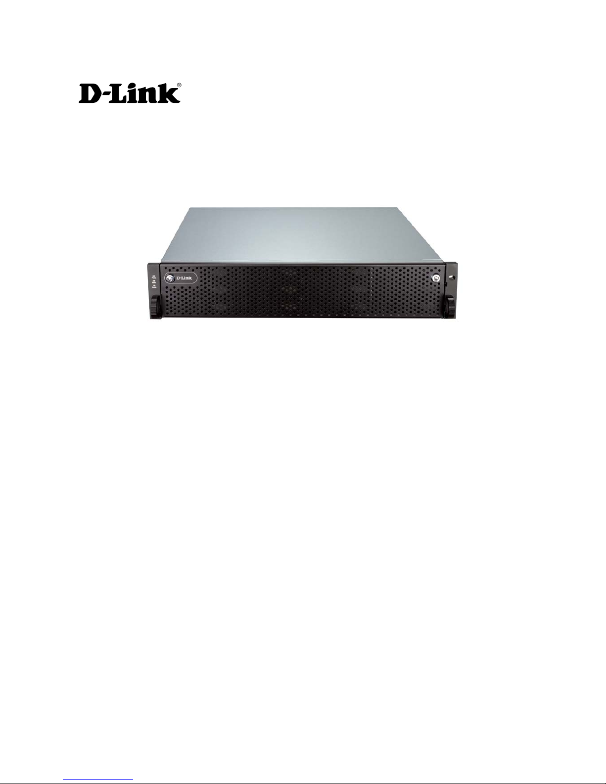
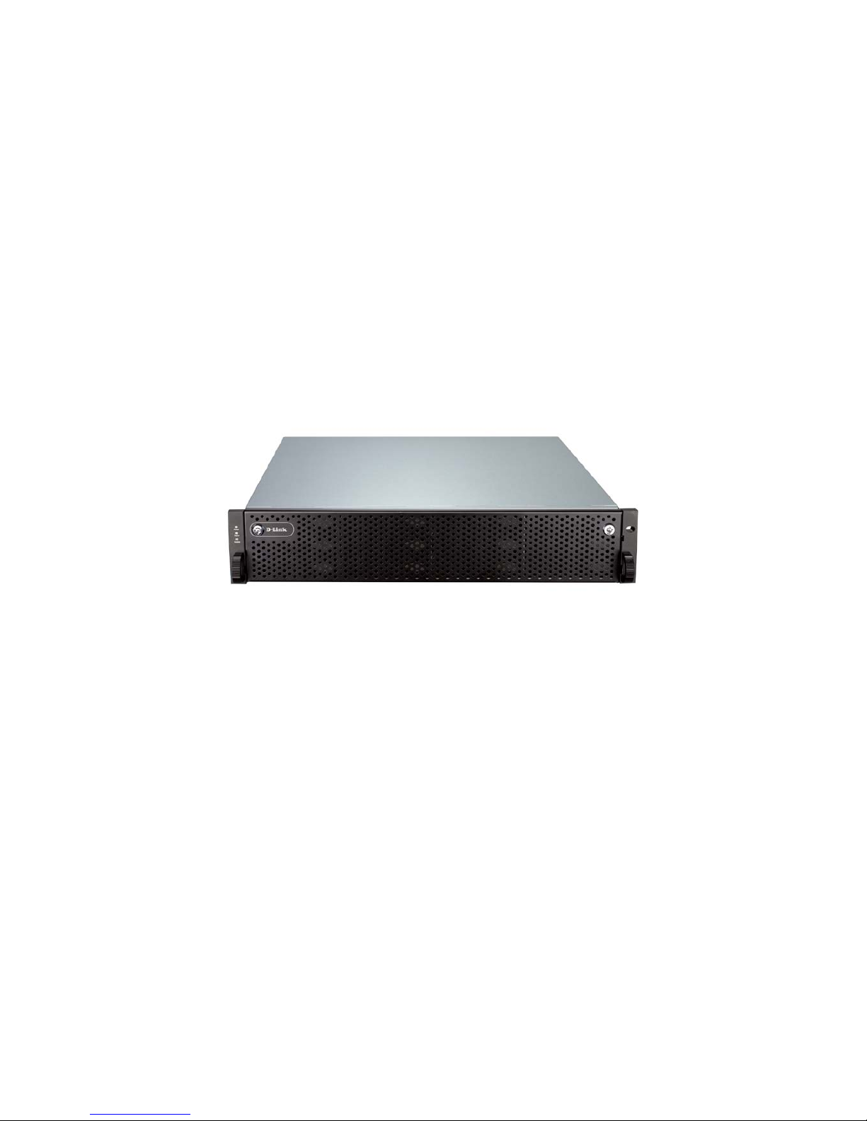
Figure 1.1.1 (DSN-6410 & 6410w/640)
Snapshot-on-the-box is a fully usable copy of a defined collection of data that c ontai ns
an image of the data as it appeared at the point in time, which means a point-in-time data
replication. It provides consistent and instant copies of data volumes without any system
downtime. Snapshot-on-the-box can keep up to 32 snapshots for one logical volume.
Rollback feature is provided for restoring the previous-snapshot data easily while
continuously using the volume for further data access. The data access which includes
read / write is working as usual without any impact to end users. The "on-the-box" implies
that it does not require any proprietary agents installed at host side. The snapshot is ta ken
at target side. It will not consume any host CPU time thus the server is dedicated to the
specific or other application. The snapshot copies can be taken manually or by schedule
every hour or every day, depends on the mo dification.
D-LINK IP SAN storage is the most cost-effective disk array system with completely
integrated high-performance and data-protection capabilities which meet or exceed the
highest industry standards, and the best da ta solutio n for small / med ium business
(SMB) and enterprise users.

7
1.1.1 Highlights
• D-LINK DSN-6410 & 6410w/640 feature highlights
Host
Interface
4 x 10GbE iSCSI ports (DSN-6410 with DSN-640)
2 x 10GbE iSCSI ports (DSN-6410)
Drive
Interface
12 x SAS or SATA II
RAID
Controllers
Dual-active RAID controllers (DSN-6410 with DSN-640)
Single controller, but can be upg radable to dual (DSN-6410)
Scalability SAS JBOD expansion port
Green Auto disk spin-down
Advanced cooling
RAID Level RAID 0, 1, 0+1, 3, 5, 6, 10, 30, 50, 60 and JBOD
N-way mirror
Compatibility Support multiple OSes, applications, 10GbE NIC, 10GbE iSCSI
HBA, and etc.
Virtualization VMWare, Hyper-V, Citrix
Data
Protection
Snapshot (Read only and Writeable), Storage base Replication
Connection
Availability
Load balancing and failover support on the 4 x 10GbE iSCSI
ports
Dimension
(W x D x H)
442.8 x 500.6 x 88.0 ( mm)
Power
Supply
2 x 500W PSU
Cache
Protection
Hot pluggable battery backup module
Fan Redundant

8
1.2 RAID concepts
RAID is the abbreviation of “Redundant Array of Independent Disks”. The basic idea of
RAID is to combine multiple drives together to form one large logical drive. This RAID
drive obtains performance, capacity and reliability than a single drive. The operating
system detects the R AID drive as a single storage device.
1.2.1 Terminology
The document uses the following terms:
• Part 1: Common
RAID Redundant Array of Independent D
isks. There are different
RAID levels with d
ifferent degree of data protection, data
availability, and performance to host environment.
PD The Physical D
isk belongs to the member disk of one specific
RAID group.
RG Raid Group. A collection of removable media. One RG consists
of a set of VDs and owns one RAID level attribute.
VD Virtual Disk. Each RD could be divided into several VDs. The VDs
from one RG have the same RAID level, but may have different
volume capacity.
LUN Logical Unit Number.
A logical unit number (LUN) is a unique
identifier whi
ch enables it to differentiate among separate
devices (each one is a logical unit ).
GUI Graphic User Interface.
RAID cell
When creating a RAID group with a compound RAID level, such as 10,
30, 50 and 60, this field indicates the number of subgroups in the RAID
group. For example, 8 disks can be grouped into a RAID group of RAID
10 with 2 cells, 4 cells. In the 2-
cell case, PD {0, 1, 2, 3} forms one RAID
1 subgro up and P D {4, 5, 6, 7} fo rm s a not h er R AI D 1 sub gr o up. In th e 4 cells, the 4 subgroups are PD {0, 1}, PD {2, 3}, PD {4, 5} and PD {6,7}.
WT Write-Through cache-
write policy. A caching technique in which
the completion of a write request is not signaled until data is
safely stored in non-
volatile media. Each data is synchronized in

9
both data cache and accessed physical disks.
WB Write-Back cache-write policy. A caching technique in which the
completion of a write request is signaled as soon as the data is
in cache and actual writing to non-
volatile media occurs at a
later time. It speeds up system wr
ite performance but needs to
bear the risk where data may be inconsistent between data
cache and the physical disks in one short time interval.
RO Set the volume to be Read-Only.
DS Dedicated S
pare disks. The spare disks are only used by one
specific RG.
Others could not use these dedicated spare disks for
any rebuilding purpose.
GS Global Spare disks. GS is shared for r ebuildin g purpose. If s ome
RGs need to use the global spare disks for rebuilding, they could
get the spare disks out from the common spa
re disks pool for
such requirement.
DG DeG
raded mode. Not all of the array’s member disks are
functioning, but the array is able to respond to application read
and write requests to its virtual disks.
SCSI Small Computer Systems Interface.
SAS Serial Attached SCSI.
S.M.A.R.T. Self-Monitoring Analysis and Reporting Technology.
WWN World Wide Name.
HBA Host Bus Adapter.
SES SCSI Enclosure Services.
NIC Network Interface Card.
BBM Battery Backup Module
• Part 2: iSCSI
iSCSI Internet Small Computer Systems Interface.
LACP Link Aggregation Control Protocol.

10
MPIO Multi-Path Input/Output.
MC/S Multiple Connections per Session
MTU Maximum Transmission Unit.
CHAP
C
hallenge Handshake Authentication
Protocol. An optional
security mechanism to control access to an iSCSI storage system
over the iSCSI data ports.
iSNS Internet Storage Name Service.
• Part 3: Dual controller
SBB Storage Bridge B
ay. The objective of the Storage Bridge Bay
Working Group (SBB) is to create a specification that defines
mechanical, electrical and low-
level enclosure management
requirements for an enclosure controller slot that will support a
variety of storage controllers from a variety of independent
hardware vendors (“IHVs”) and system vendors.
• Part 4: 10GbE
SFP+ Small Form-factor Pluggable is a compact, hot-pluggable
transceiver used for both Fibre Channel and 10GbE.
CX4 10GBASE-CX4, a cop per based 10 Gigabit Ethernet PHY.
1.2.2 RAID levels
There are different RAID levels with different degree of data protection, data availability,
and performance to host environment. The description of RAID levels are on the following:
RAID 0 Disk striping. RAID 0 needs at least one hard drive.
RAID 1 Disk mirroring over two disks. RAID 1 needs at least two hard drives.
N-way mirror Extension to RAID 1 level. It has N copies of the disk.
RAID 3 Striping with parity on the dedicated disk. RAID 3 needs at least three
hard drives.
RAID 5
Striping with interspersed parity over the member disks. RAID 3
needs at least three hard drives.
11
RAID 6 2-dim
ensional parity protection over the member disks. RAID 6 needs
at least four hard drives.
RAID 0+1
Mirroring of the member RAID 0 volumes. RAID 0+1 needs at least
four hard drives.
RAID 10
Striping over the member RAID 1 volumes. RAID 10 needs at least
four hard drives.
RAID 30
Striping over the member RAID 3 volumes. RAID 30 needs at least six
hard drives.
RAID 50
Striping over the member RAID 5 volumes. RAID 50 needs at least six
hard drives.
RAID 60 Striping over the member RAID 6 volumes. RAID 60 n
eeds at least
eight hard drives.
JBOD The abbreviation of “Just a Bunch Of Disks”
. JBOD needs at least
one hard drive.
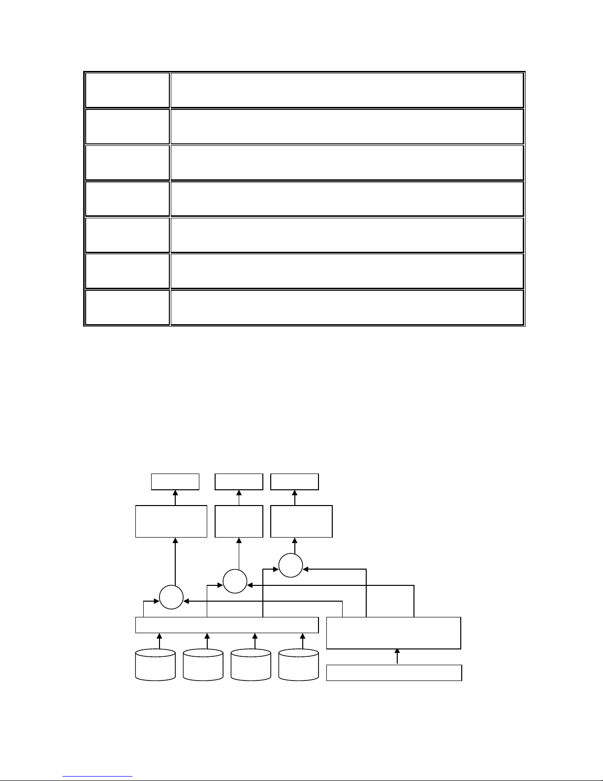
1.2.3 Volume relationship
The below graphic is the volume structure which D-LINK has designed. It describes the
relationship of RAID components. One RG (RAID group) consists of a set of VDs (Virtual
Disk) and owns one RAID level attribute. Each RG can be divided into several VDs. The
VDs in one RG share the same RAID level, but may have different volume capacity. All
VDs share the CV (Cache Volume) to execute the data transaction. LUN (Logical Unit
Number) is a unique identifier, in which users can access through SCSI command s.
Figure 1.2.3.1
PD 2 PD 3 DS PD 1
VD 1
VD 2
Snapshot
VD
Cache Volume
+++
12
1.3 iSCSI concepts
iSCSI (Internet SCSI) is a protocol which encapsulates SCSI (Small Computer System
Interface) commands and data in TCP/IP packets for linking storage devices with servers
over common IP infrastructu res. iSCSI provides high performanc e SANs over standard IP
networks like LAN, WAN or the Internet.
IP SANs are true SANs (Storage Area Networks) which allow several servers to attach to
an infinite number of storage volumes by using iSCSI over TCP/IP networks. IP SANs can
scale the storage capacity with any type and brand of storage system. In addition, i t can
be used by any type of network (Ethernet, Fast Ethernet, Gigabit Ethernet, and 10 Gigabit
Ethernet) and combination of operating systems (Microsoft Windows, Linux, Solaris, Mac,
etc.) within the SAN network. IP-SANs also include mechanisms for security, data
replication, multi-path and high availability.
Storage protocol, such as iSCSI, has “two ends” in the connection. These ends are initiator
and target. In iSCSI, we call them iSCSI initiator and iSCSI target. The iSCSI initiator
requests or initiates any iSCSI communication. It requests all SCSI operations like read or
write. An initiator is usually located on the host side (either an iSCSI HBA or iSCSI SW
initiator).
The target is the storage device itself or an appliance which controls and serves volumes
or virtual volumes. The target is the device which performs SCSI command or bridge to an
attached storage device.
Figure 1.3.1
The host side needs an iSCSI initiator. The initiator is a driver which handles the SCSI
traffic over iSCSI. The initiator can be software or hardware (HBA). Please refer to the
certification list of iSCSI HBA(s) in Appendix A. OS native initiators or other software
iSCSI device 1
(target)
Host 1
(initiator)
NIC
IP SAN
Host 2
(initiator)
iSCSI
HBA
iSCSI device 2
(target)

13
initiators use standard TCP/IP stack and Ethernet hardware, while iSCSI HBA(s) use their
own iSCSI and TCP/IP stacks on board.
Hardware iSCSI HBA(s) provide its own initiator tool. Please refer to the vendors’ HBA user
manual. Microsoft, Linux, Solaris and Mac provide iSCSI initiator driver. Please contact D-
LINK for the latest certification list. Below are the available links:
1. Link to download the Microsoft iSCSI software initiator:
http://www.microsoft.com/downloads/details.aspx?FamilyID=12cb3c1a-15d6-4585b385-befd1319f825&DisplayLang=en
2. In current Linux distributions, OS built-in iSCSI initiators are usually available. For
different kernels, there are different iSCSI drivers. Please check Appendix A for iSCSI
initiator certification list. If user needs the latest Linux iSCSI initiator, please visit
Open-iSCSI project for most update information. Linux-iSCSI (sfnet) and Open-iSCSI
projects merged in April 11, 2005.
Open-iSCSI website: http://www.open-iscsi.org/
Open-iSCSI README: http://www.open-iscsi.org/docs/README
Features: http://www.open-iscsi.org/cgi-bin/wiki.pl/Roadmap
Support Kernels:
http://www.open-iscsi.org/cgi-bin/wiki.pl/Supported_Kernels
Google groups:
http://groups.google.com/group/open-iscsi/threads?gvc=2
http://groups.google.com/group/open-iscsi/topics
Open-iSCSI Wiki: http://www.open-iscsi.org/cgi-bin/wiki.pl
3. ATTO iSCSI initiator is available for Mac.
Website: http://www.attotech.com/xtend.html
4. Solaris iSCSI initia tor
Version: Solaris 10 u6 (10/08)
1.4 IP SAN storage specifications
1.4.1 Technical specifications
• Controller features
1. Dual-active configuration support (only for DSN-6410 with DSN-640)
2. Better performance, when comparing to other competitors' products in the same
segment
3. Cache mirroring through high bandwidth channels (only for DSN-6410 with DSN-
640)

14
4. Flexible RAID group (RG) own ers hip mana geme nt (only for DSN-6410 with DSN-
640)
Each RG can be assigned to one of the two controllers
Each LUN can be exported from both controllers
5. Management port seamless take-over (only for DSN-6410 with DSN-640)
The management port can be transferred smoothly to the other controller with
the same IP address
6. Online firmware upgrade, no system down time (only for DSN-6410 with DSN-
640)
7. Multiple target iSCSI nodes per controller support
Each LUN can be attached to one of 32 nodes from each cont roller
8. Front-end 2 x 10GbE iSCSI ports with high availability/load balancing/fail-over support
per controller
Microsoft MPIO, MC/S, Trunking, LACP, and etc .
9. SBB Compliant
• System key components
1. CPU: Intel Xscale IOP 81342
2. Memory: 4GB DDRII 533 DIMM
3. Hardware iSCSI off-load engine
4. 2 x UARTs: serial console mana gement and UPS
5. Fast Ethernet port for web-based management use
6. Backend: 12 x SAS or SATA II drive connections
7. Front-end: 2 x 10GbE iSCSI ports per controller
8. Hot pluggable BBM
9. SAS JBOD expansion port for expansion
10. Multiplexer board support for SATA drives (optional, on Dual controller mode)
11. Two power supplies
12. Redundant fans
• RAID and volume operation
1. RAID level: 0,1,0+1,3,5,6,10,3 0,50, 60, JBOD, an d N-way mirror
2. Up to 1024 logical volumes in the system
3. Up to 32 PDs can be included in one volume group
4. Global and dedicated hot spare disks
5. Write-through or write-back cache polic y for different application usage
6. Multiple RAID volumes support
7. Configurable RAI D stripe size
8. Online volume expansion
9. Instant RAID volume avail ability
10. Auto volume rebuilding
11. On-line volume migration with no system down-time
• Advanced data protection
1. D-Link writeable snap shot

15
Built-in snapshot with rollback enabled
Snapshot enabled up to 16 volumes, each logical volume supports up to 32
snapshot volumes, total 512 snapshot vo lumes per system
2. Microsoft Windows Volume Shadow Copy Services (VSS)
3. Configurable N-way mirror for high data protection
4. Online disk roaming
5. Instant volume confi guration restoration
6. Smart faulty sector r elocation
7. Hot pluggable battery backup module support
• Enclosure monitoring
1. S.E.S. inband management
2. UPS management via dedic ated serial port
3. Fan speed monitors
4. Redundant power supp l y m onitors
5. Voltage monitors
6. Thermal sensors for both RAID controller and enclosure
7. Status monitor s for D-LINK SAS JBODs
• Management interface
1. Management UI via
serial console
SSH telnet
HTTP Web UI
secured Web (HTTPS)
2. Notification via
Email
SNMP trap
Browser pop-up windows
Syslog
Windows Messenger
3. iSNS support
4. DHCP support
• iSCSI features
1. iSCSI jumbo frame support
2. Header/Data digest support
3. CHAP authentication enabled
4. Load-balancing and failover throug h M PIO, MC/S, Trunking, and LACP
5. Up to 32 multiple nodes support
6. VLAN support
• Host connection
1. 2 x 10GbE iSCSI ports per controller

16
2. Host access control: Read-Write and Read-Only
3. Up to 128 sessions per controller
4. One logic volume can b e shared by as many as 16 hosts
• OS support
Windows
Linux
Solaris
Mac
• Drive support
1. SAS
2. SATA II (optional)
3. SCSI-3 compliant
4. Multiple IO tra nsaction processing
5. Tagged command queuing
6. Disk auto spin-down support
7. S.M.A.R.T. for SATA II drives
8. SAS JBODs expansion
• Power and Environment
AC input: 100-240V ~ 7A-4A 500W with PFC (Auto Switchi ng)
DC output: 3.3V-21A; 5V-39A; 12V-30A
Operating Temperature: 0 to 40 ℃
Relative Humidity: 5% to 95% non-condensing
• Dimensions
2U 12 bay 19 inch rackmount chassis
442.8mm x 500.6mm x 88.0mm (W x D x H)
1.4.2 FCC and CE statements
FCC statement
This device has been shown to be in compliance with and was tested in accordance with
the measurement procedures specified in the Standards and Specifications listed below
and as indicated in the measurement report number: xxxxxxxx-F
Technical Standard: FCC Part 15 Class A (Verification)
IC ICES-003
CE statement

17
This device has been shown to be in compliance with and was tested in accordance with
the measurement procedures specified in the Standards and Specifications listed below
and as indicated in the measurement report number: xxxxxxxx-E
Technical Standard: EMC DIRECTIVE 2004/108/EC
(EN55022 / EN55024)
UL statement
FCC statement
This device has been shown to be in compliance with and was tested in accordance with
the measurement procedures specified in the Standards and Specifications listed below
and as indicated in the measurement report number: xxxxxxxx-F
Technical Standard: FCC Part 15 Class A (Verification)
IC ICES-003
CE statement
This device has been shown to be in compliance with and was tested in accordance with
the measurement procedures specified in the Standards and Specifications listed below
and as indicated in the measurement report number: xxxxxxxx-E
Technical Standard: EMC DIRECTIVE 2004/108/EC
(EN55022 / EN55024)
UL statement
Rack Mount Instructions - The following or similar rack-mount instructions are included
with the installation instructions:
A. Elevated Operating Ambient - If installed in a closed or multi-unit rack assembly, the
operating ambient temperature of the rack environment may be greater than room
ambient. Therefore, consideration should be given to installing the equipment in an
environment compatible with the maximum ambient temperature (Tma) specified by
the manufacturer.
B. Reduced Air Flow - Installation of the equipment in a rack should be such that the
amount of air flow required for safe operation of the equipment is not compromised.
C. Mechanical Loading - Mounting of the equipment in the rack should be such that a
hazardous condition is not ac hieved due to uneven mechanical loading.
D. Circuit Overloading - Consideration should be given to the connection of the
equipment to the supply circuit and the effect that overloading of the circuits might
have on overcurrent protection and supply wiring. Appropriate consideration of
equipment nameplate ratings should be used when addressing this concern.
18
E. Reliable Earthing - Reliable earthing of rack-mounted equipment should be
maintained. Particular attention should be given to supply connections other than
direct connections to the branch circ uit (e.g. use of power strips).
Caution
The main purpose of the handles is for rack mount use only. Do not use the
handles to carry or transport the systems.
The ITE is not intended to be installed and used in a home, school or public area
accessible to the general population, and the thumbscrews should be tightened with a tool
after both initial installation and subsequent access to the panel.
Warning: Remove all power supply c ords before service
This equipment intended for installation in restricted access location.
Access can only be gained by SERVICE PERSONS or by USERS who have been
instructed about the reasons for the restrictions applied to the location and about any
precautions that shall be taken.
Access is through the use of a TOOL or lock and key, or other means of security, and
is controlled by the authority responsible for the location.
Caution
Risk of explosion if battery is replaced by incorrect type. Dispose of used
batteries according to the instructions.
19
Chapter 2 Installation
2.1 Package contents
The package contains the following items:
1. DSN-6410 & 6410w/640 IP SAN storage (x1)
2. HDD trays (x12)
3. Power cords (x4)
4. RS-232 cables (x2), one is for console, the other is for UPS.
5. CD (x1)
6. Rail kit (x1 set)
7. Keys, screws for drives and rail kit (x1 packet)
8. SFP and 5 Meter cable
2.2 Before installation
Before starting, prepare the following items.
1. A host with a Gigabit Ethernet NIC or iSCSI HBA.
2. CAT 5e, or CAT 6 network cables for management port and iSCSI data ports.
3. Prepare storage system configuration plan.
4. Prepare management port and iSCSI data ports network information. When using
static IP, please p repare static IP addresses, subnet mask, a n d default gateway.
5. 10GbE switches (recommended). Or 10GbE switches with LCAP / Trunking (optional).
6. CHAP security information, including CHAP username and secret (optional).
2.3 Enclosure
2.3.1 Front view
Figure 2.3.1.1 (DSN-6410 & 6410w/640)
Drive slot numbering
Slot 1
Slot 4
Slot 7
Slot 10
Slot 2 Slot 5 Slot 8 Slot 11
Slot 3 Slot 6 Slot 9 Slot 12
20
The drives can be installed into any slot in the enclosure. Slot numbering will be reflected
in web UI.
Tips
It is advisable to install at least one drive in slots 1 ~ 4. System event logs
are saved to drives in these slots; If no drives are fitted the event log
s will
be lost in the event of a system reboot.
2.3.2 Front LED lights
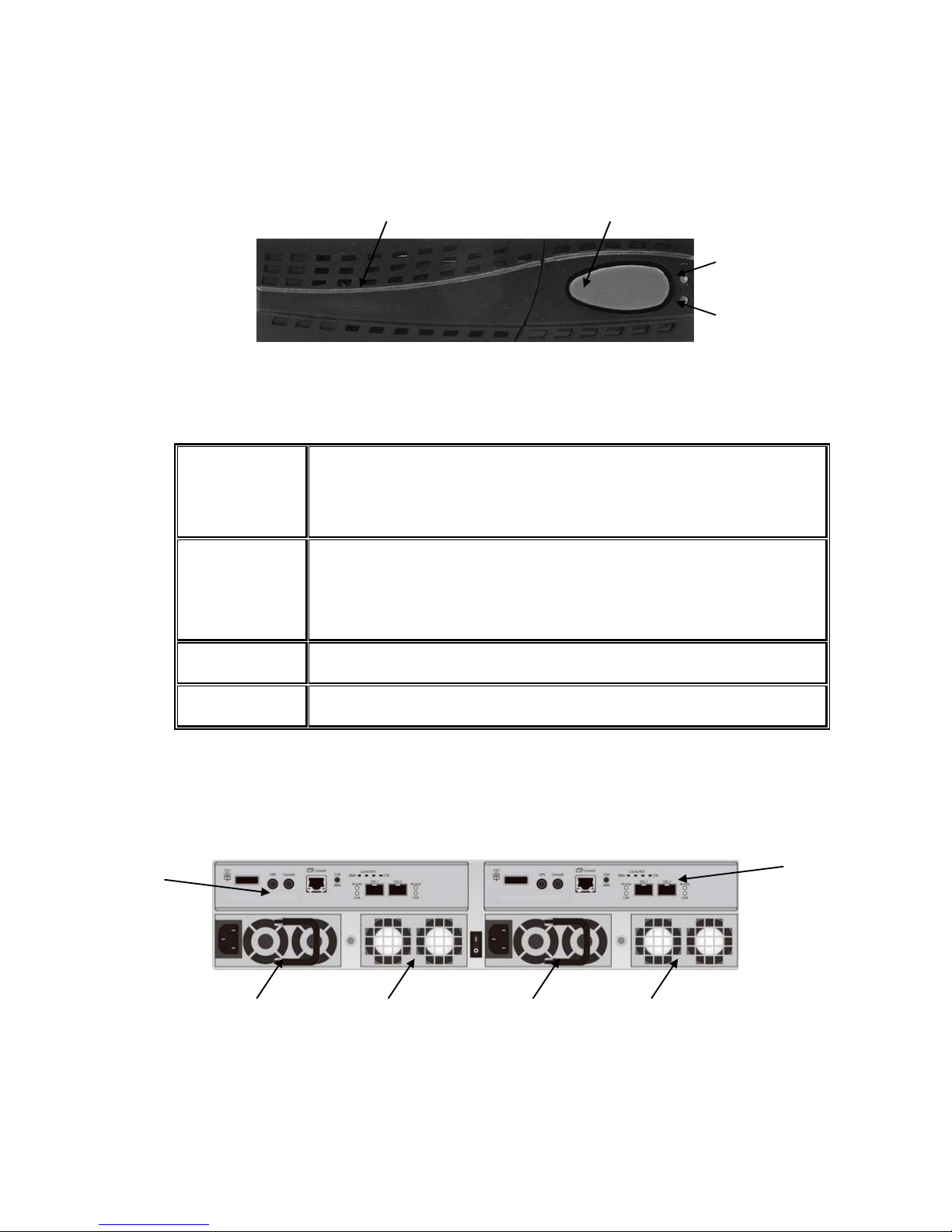
There are three LED lights on the left frame bar.
Figure 2.3.2.1
• LED lights description:
Power LED:
Green Power on.
Off Power off.
Status LED:
Red System is failure.
Off System is good.
Access LED:
Blue Host is accessing.
Off Host is no access.
21
2.3.3 Install drives
Note : Skip this section if you purchased a solution populated with drives.
To install SAS or SATA drives with no Bridge Board use the front mounting holes:
To install SATA drives with Bridge Boa r d (DSN-654), fit the Bridge Board first
Then install the drive using the rear mounting holes:
22
Figure 2.3.3.3
• HDD tray description:
HDD power LED:
Green HDD is inserted and good.
Off No HDD.
HDD access LED:
Blue blinking HDD is accessing.
Off No HDD.
HDD tray handhold.
Latch for tray kit removal.
2.3.4 Rear view
Figure 2.3.4.1 (DSN-6410 with DSN-640 SFP+)
• PSU and Fan module description:
23
Controller 2. (only on DSN-6410 with DSN-640)
Controller 1.
Power supply unit (PSU1).
Fan module (FAN1 / FAN2).
Power supply unit (PSU2).
Fan module (FAN3 / FAN4).
24
Figure 2.3.4.3 (DSN-6410 SFP+)
• Connector, LED and button description:
10GbE ports (x2).
Link LED:
Orange
Asserted when a 1G link is established and
maintained.
Blue
Asserted when a 10G link is establish and
maintained.
Access LED:
Yellow
Asserted when the link is established and
packets are b
eing transmitted along with any receive
activity.
LED (from right to left)
Controller Health LED:
Green Controller status normal or in the booting.
Red Other than above status.
Master Slave LED: (only for DSN-6410 with DSN-640)
Green Master controller.
Off Slave controller.
Dirty Cache LED:
Orange Data on the cache waiting for flush to disks.
Off No data on the cach e .
BBM LED:
Green BBM installed and powered
Off No BBM

25
BBM Status Button:
When the system power is off, press the BBM status button,
if the BBM LED is Green, then the BBM still has power to
keep data on the cache. If not, then the BBM power is ran
out and cannot keep the data on the cache anymore.
Management port.
Console port.
RS 232 port for UPS.
SAS JBOD expansion port.
2.4 Install battery backup module
To install the IP SAN storage with a battery backup module, please follow the procedure.
Figure 2.4.1
1. BBM (Battery Backup Module) supports hot pluggable. Regardless of the IP SAN
storage is turned on or off.
2. Remove the cover of BBM.
3. Insert the BBM.
4. Tighten the BBM and use screws to lock the both sides.
5. Done.
26
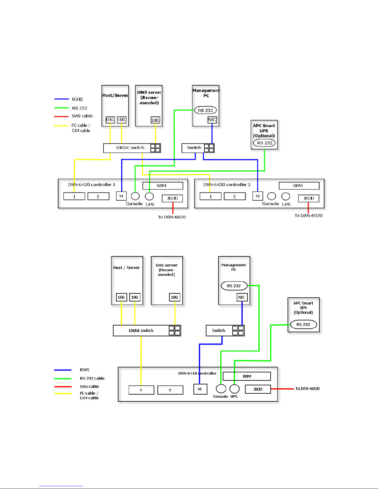
2.5 Deployment
Please refer to the following topology and have all the connections ready.
Figure 2.5.1 (DSN-6410 with DSN-640)
Figure 2.5.2 (DSN-6410)
1. Setup the hardware connection before power on servers. Connect console cable,
management port cable, and iSCSI data port cables in advance.
27
2. In addition, installing an iSNS server is recommended for dual controller system.
3. Power on the DSN-6410 or DSN-6410w/DSN-640 and the DSN-6020 (optional)
first, and then power on hosts and iSNS server .
4. Host server is suggested to logon the target twice (both controller 1 and controller 2),
and then MPIO should be setup automatically. (only for DSN-6410 with DSN-640)
Tips
iSNS server is recommended for dual controller system.
For better data service availability, all the connections among host servers, 10GbE
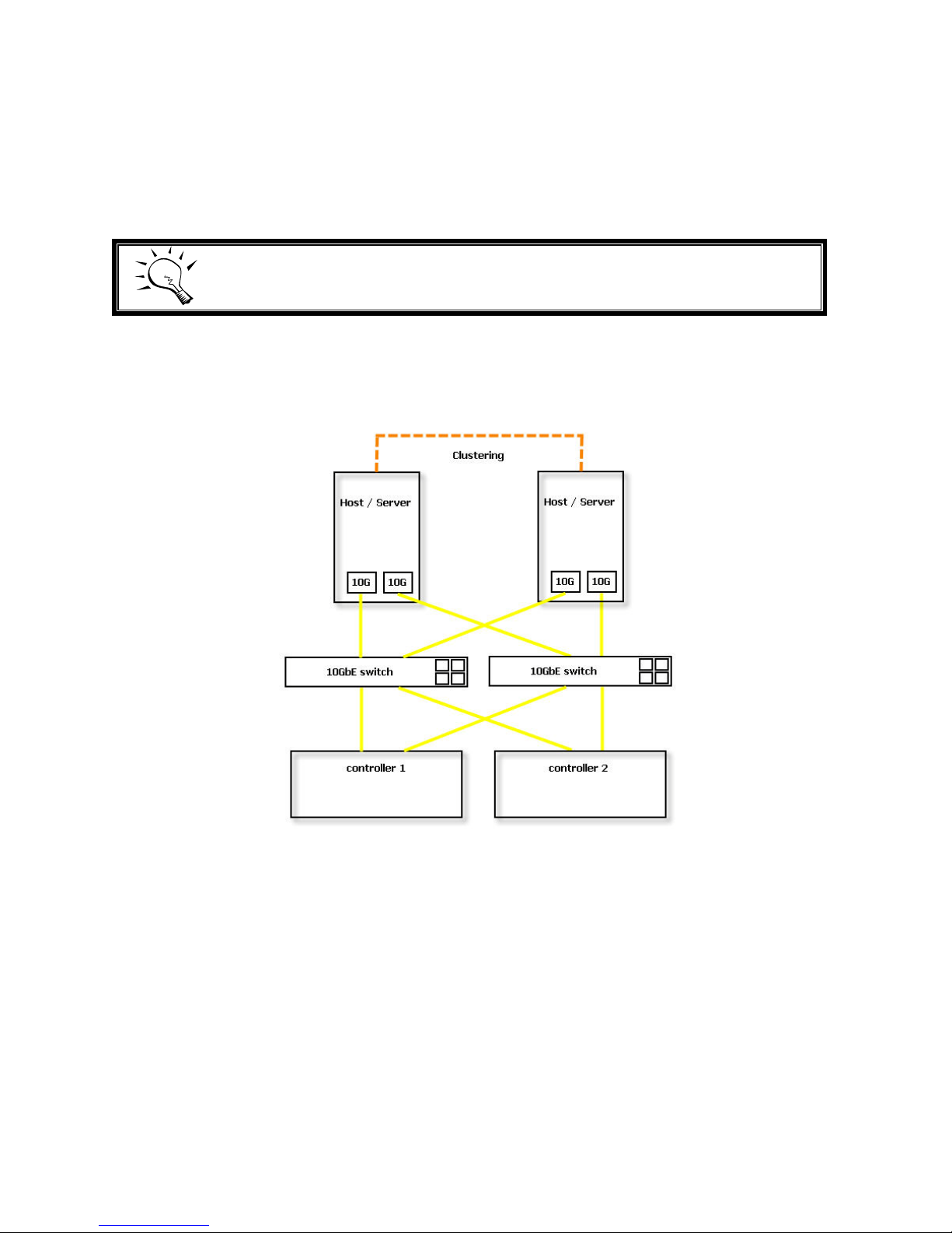
switches, and the dual controllers are recommended as redundant as below.
Figure 2.5.3 (only for DSN-6410 with DSN-640)
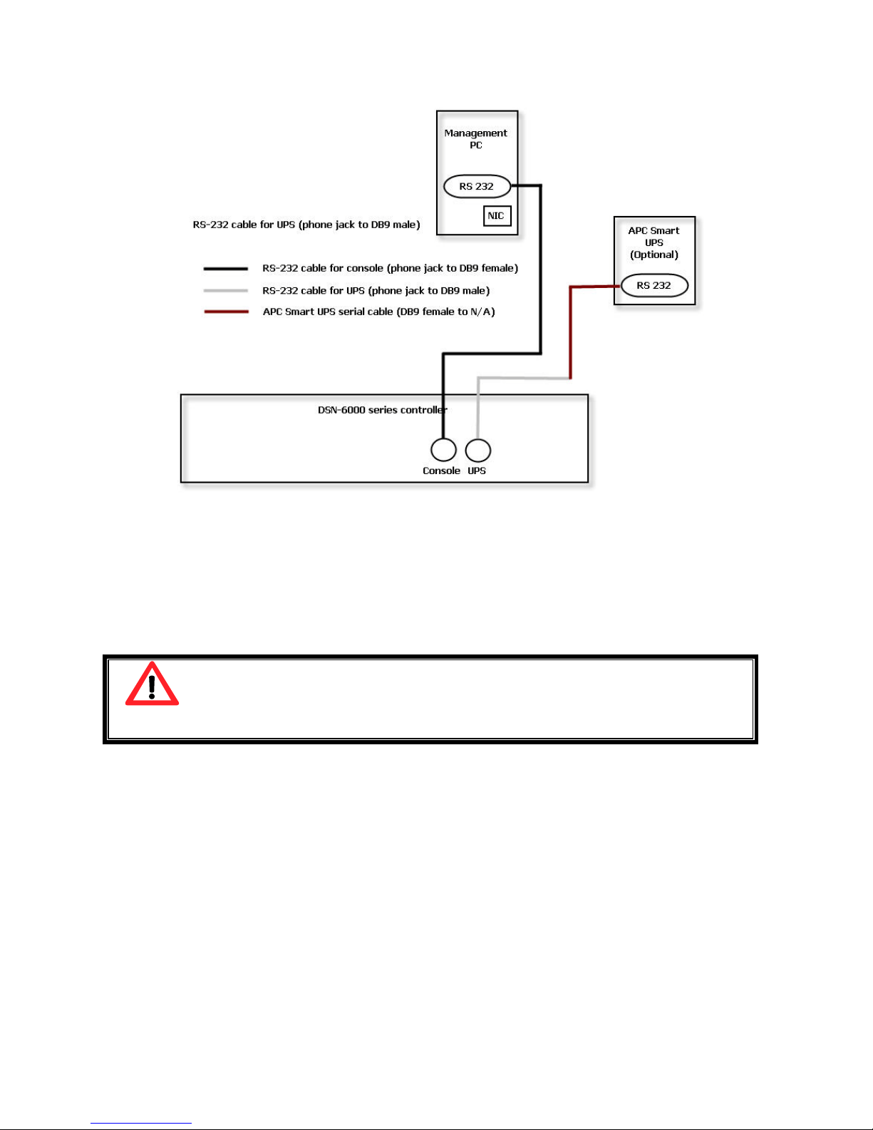
The following topology is the connections for console and UPS (optional).
28
Figure 2.5.4
1. Using RS-232 cable for console (back color, phone jack to DB9 female) to connect
from controller to management PC directly.
2. Using RS-232 cable for UPS (gray color, phone jack to DB9 male) to connect from
controller to APC Smart UPS serial cable (DB9 female side), and then connect the
serial cable to APC Smart UPS.
Caution
It may not work when connecting the RS-
232 cable for UPS (gray color,
phone jack to DB9 male) to APC Smart UPS directly.

29
Chapter 3 Quick setup
3.1 Management interfaces
There are three management methods to manage D-LINK IP SAN storage, describe in
the following:
3.1.1 Serial console
Use console cable (NULL mode m cable) to connect from console port of D-LINK IP SAN
storage to RS 232 port of management PC. Please refer to figure 2.3.1. The console
settings are on the following:
Baud rate: 115200, 8 data bit, no parity, 1 stop bit, and no flow control.
Terminal type: vt100
Login name: admin
Default password: 123456
3.1.2 Remote control
SSH (secure shell) software is required for remote login. The SSH client software is
available at the following web site:
SSH Tectia Client: http://www.ssh.com/
PuTTY: http://www.chiark.greenend.org.uk/
Host name: 192.168.0.32 (Please check the DHCP address first on LCM.)
Login name: admin
Default password: 123456
Tips
D-LINK product supp orts SSH for remote control
only. For using SSH, the
IP address and password are required for login.
30
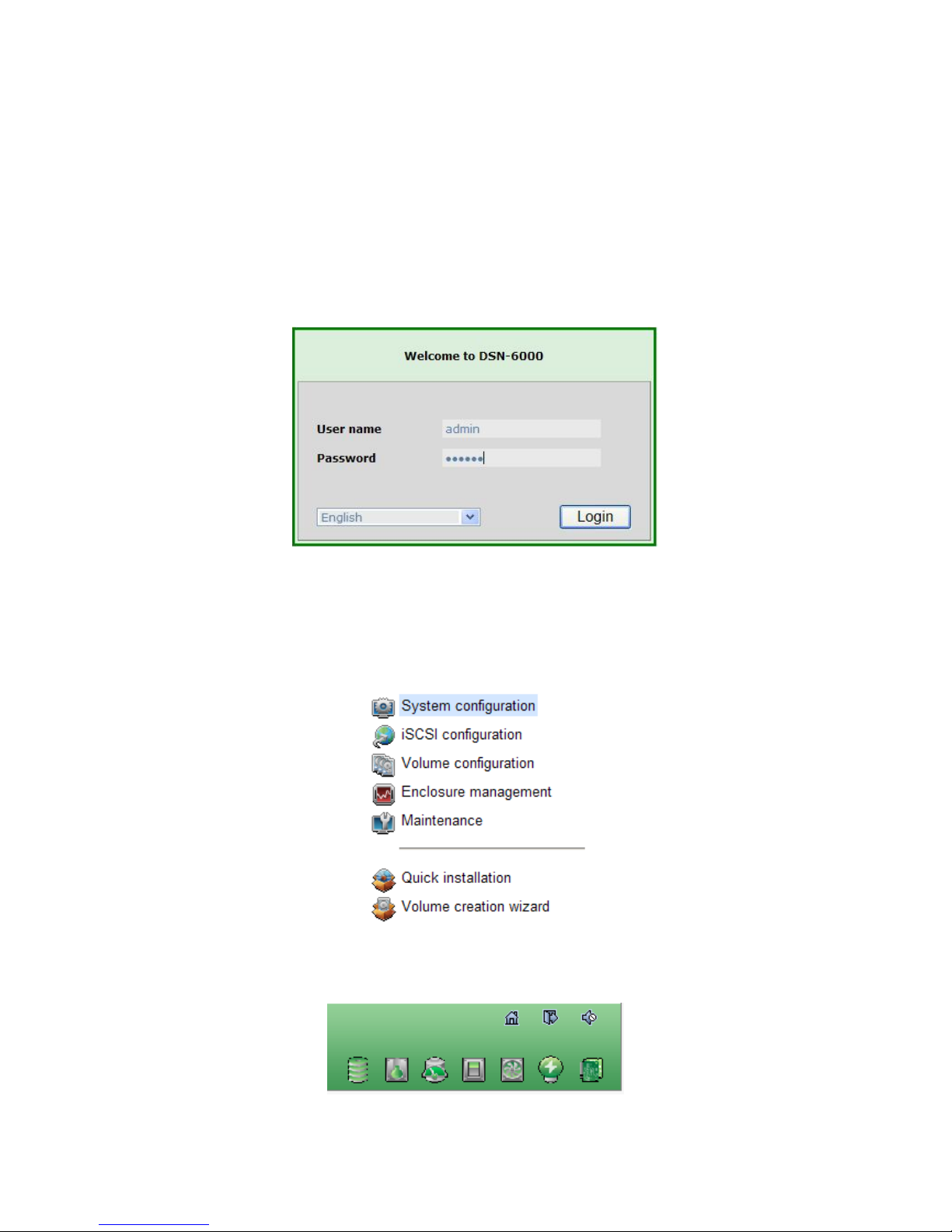
3.1.3 Web UI
D-LINK IP SAN storage supports graphic user interface (GUI) to operate. Be sure to
connect the LAN cable. The default I P sett i ng is DHCP; open the browser and enter:
http://192.168.0.32
And then it will pop up a dialog for authentication.
Figure 3.1.4.1
User name: admin
Default password: 123456
After login, choose the functions which lists on the left side of window to make any
configuration.
Figure 3.1.4.2
There are seven indicators and three icons at the top-right corner.
Figure 3.1.4.3
 Loading...