

D-Link DSN-5110-10, DSN-5210-10, DSN-5410-10 Quick Start Manual
Page 1
DSN-5xx0 (5110-10, 5210-10, 5410-10) - 5/2010
Copyright © 2010 D-Link, Inc. - All Rights Reserved
P
R I M A R Y
A
R R A Y
DSN-5xx0-10 Primary Array
Quick Start Guide
The DSN-5xx0 Primary Array Quick Start Guide provides the
information needed to get your DSN-5xx0-10 primary array
out of the box and operational with a connection to a host
computer. Follow the simple instructions in this guide, and in
no time at all you will be part of the iSCSI revolution.
Important Safety Information:
Before you install the DSN-5xx0-10 primary array, please read
all documentation provided on the Product CD.
The DSN-5xx0-10 primary array is available in either single or
dual controller configurations. The dual-controller systems
offer automatic failover capability for High Availability in the
event of a controller failure. Each controller can have either
four (DSN-5110-10 and DSN-510) or eight (DSN-5210-10 and
DSN-520) 1-GbE data ports or one (DSN-5410-10) 10-GbE data
port in each controller for iSCSI communication. Each
controller comes with 512 MB of system memory and 1 GB
(DSN-5110-10 and DSN-510) or 2 GB (DSN-5210, DSN-520, DSN5410-10, DSN-540) of buffer memory. The DSN-5xx0-10
primary array can support a total of 4 GB of buffer memory.
For systems with two controllers, both controllers must have
the same number and type of data ports, the same amount of
Buffer Memory, and the same version of software.
1 Unpack the Package Contents
Before unpacking, inspect the container for damage. If damage
exists, file a claim with the carrier. Remove the items from the
container and compare them to the packing list:
One DSN-5xx0-10 primary array (includes backplane, up to 12
drive carriers with drive blanks, two power supplies, 48 drive
carrier screws holding drive blanks, and one canister filler plate)
One controller with memory and battery in canisters, inserted
into the rear of the DSN-5xx0-10 primary array.
One rack-mount kit in a box (includes rails, mounting hardware,
and instructions)
Six power cords, one RS-232 diagnostic cable, one DSN-5000
Series Product CD.
One set of packing materials and cartons
If contents are missing or damaged please contact your supplier.
Save all packing materials in case you have to return the unit.
2 What Else You Need
To complete the primary array installation, you need:
A computer that will act as the iSCSI initiator (see step 7).
Please refer to the D-Link Interoperability matrix at:
http://www.dlink.com for tested operating systems, Network
Interface Cards (NICs), Host Bus Adapters (HBAs), and network
infrastructure.
A static IP address and Category 6 or 5E (for 1-GbE) or fiber
optical (for 10-GbE) network cable for each DSN-5xx0 primary
array data port that will connect to your SAN.
XFP modules for optical connection (10-GbE systems only)
Ethernet switch (1-GbE for DSN-5110-10 & DSN-5210-10, or 10-
GbE for DSN-5410-10) required for dual-controller systems
Independent AC power supply within 6 feet of the primary array
Disk drives: refer to the DSN-5000 Series Hardware Reference
Guide for disk drive installation
Note: The DSN-5xx0-10 primary array can support SAS or SATA
hard disk drives from a variety of manufacturers (48 for the DSN5110-10 and 84 for the DSN-5210-10 & 5410-10). It is possible
(but not recommended) to mix SAS and SATA drives in the same
array. Also, if you anticipate using dual controllers for HA
operation, SAS drives are required.
Optional: In addition, a separate computer may be used as the
Management console (see Step 8)
Optional, but recommended: Uninterruptible power supply
3 Rack-Mount Instructions
The DSN-5xx0-10 primary array can be mounted in a standard
19-inch rack using the rack-mount kit provided with the DSN5xx0 primary array.
Note: The rack cabinet must provide sufficient airflow to the
front and rear of the DSN-5xx0-10 primary array for correct
cooling. Ventilation must be sufficient to exhaust heat from the
rear of the equipment in the rack. Plan the rack installation
with the heaviest item on the bottom of rack.
A. Ensure that power is not being applied to the DSN-5xx0
primary array by removing the power cords before attaching
the mounting hardware provided to the left and right sides
of the rack supporting the DSN-5xx0-10 primary array.
B. With the help of another person, slide the DSN-5xx0-10
primary array into place (without drives installed) and
secure with the mounting hardware.
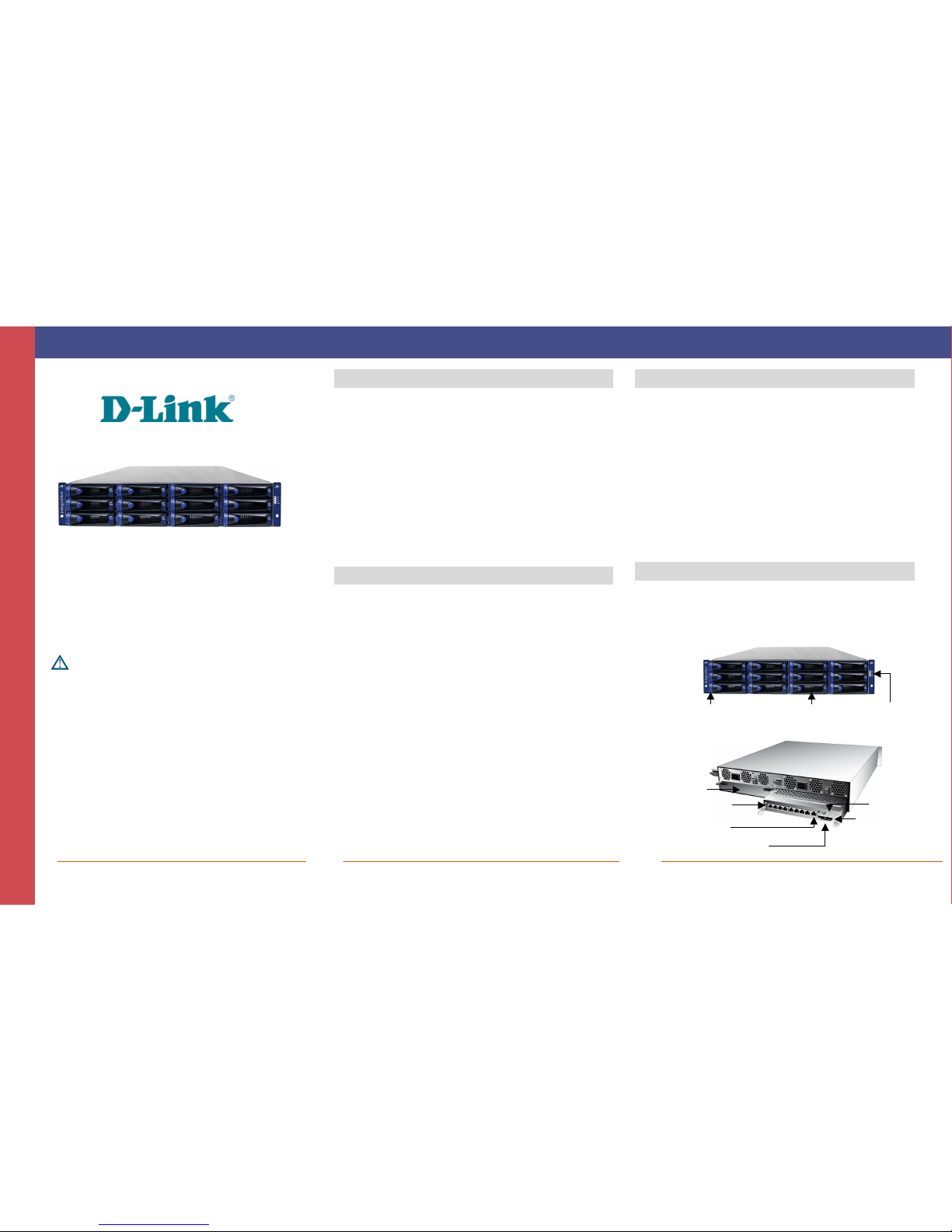
4 Install the DSN-5xx0-10 Primary Array
The DSN-5xx0-10 primary array is a full iSCSI storage subsystem,
with up to 12 SATA or SAS disks, and additional storage available
through add-on expansion arrays. Enclosure and drive carrier LEDs
illuminate on the front of the unit, while interface ports, buttons,
and LEDs for port speed, port activity, and status are at the rear.
Note: Be sure that empty drive carriers are replaced by drive
blanks in all drive slots that are not occupied by a drive.
Rear View
(DSN-5210-10 shown)
Four or Eight 1
-
GbE
iSCSI Data Ports
Rear Panel Status
LEDs and Switches
Two Expansion Ports
One Management Port
Front View
Enclosure LEDs
Drive Carrier LEDs
Dri
ve Carrier
Primary Controller in Slot #0
Redundant Controller
or Filler Plate in Slot #1
Page 2
Contact Information
For more information about the DSN-5xx0-10 Primary Array
Web site: http://www.dlink.com/
No part of this document may be reproduced or transmitted in any form or by any means, electronic or mechanical, including photocopying and recording, or stored in a database or retrieval system, without the expressed written approval of D-Link, Inc.
D-Link reserves the right to make changes to this document at any time without notice and assumes no responsibility for its use. This document contains the most current information available at the time of publication. However, all of the features described in this document may not be currently available.
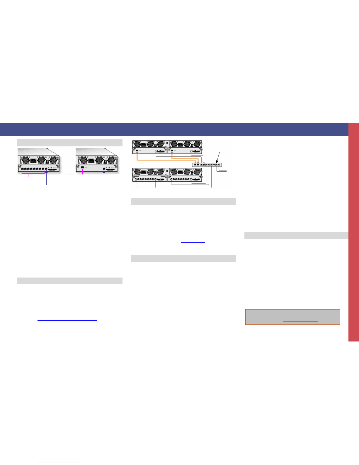
5 Connect to the DSN-5xx0-10 Primary Array
Identifying the Data and Management Ports
A. Attach an Ethernet cable to the iSCSI 0 data port on the primary
controller of the DSN-5xx0-10 primary array rear panel and to your
SAN switch. To connect additional data ports to your SAN, repeat
this step using another Ethernet cable and the next data port, up to
the number of data ports on the controller. If you have dual
controllers, repeat this step for the redundant controller.
B. On the rear of each controller of the DSN-5xx0-10 primary array,
the management port is the 10/100/1000 RJ-45 port labeled
MGMT. If you have dual controllers, you must connect the
management port of both controllers to your network switch. If
you have a single controller, you can directly connect this port to
your Management Host using a standard Ethernet cable for a GbE
host port or a crossover cable for a 10/100 host port. Out of the
box, the active management port defaults to the IP address
192.168.1.1. This can be changed using the Start-up Wizard.
C. The diagnostic port (stereo jack) labeled DIAG is used for
diagnostic purposes only. If needed, use the supplied RS-232
cable to connect this port to a computer serial port configured
for a baud rate of 115,200 bps at 8 data bits, no parity bit, and 1
stop bit.
6 Prepare Your Server
This guide assumes that Microsoft Windows 2003 Server or
later will be used for product set up. Other operating systems
are supported (see step 2), but in this guide, Microsoft
Windows 2003 Server will be used. The server must have a
10/100/1000 Gbps NIC. All updates, Service Packs, and
drivers for the operating system and NIC must be installed. If
your server uses the NIC for iSCSI storage access, install the
latest supported version of the Microsoft iSCSI initiator
software at: http://www.microsoft.com/downloads.
Connecting the iSCSI Data Port(s) and Management Port
7 Prepare the Management Host
A. The management port on the primary controller of the DSN-5xx0
primary array has an IP address of 192.168.1.1. Therefore, to
start with, the NIC must have a fixed IP address of
192.168.1.n (e.g., 192.168.1.2). After you set up the DSN5xx0 primary array via the Start-Up Wizard, the management
port can be changed to the desired IP address (for example, to
use on your corporate LAN).
B. Download Java Runtime Environment 6 (JRE 6), v1.6.0.0 or later.
That software is available at: http://java.com.
Note: Attempting to install the Java Runtime Environment 6 on a
non-supported version of Windows or a computer whose Service Packs
are out of date will display an error message.
8 First-Time Startup
A. Plug the two power cords into the AC source (for best practices,
the second power receptacle should be on a different circuit).
B. Power up the primary array by turning on both rocker switches
on both power supplies at the rear of the unit. The system starts
to boot:
The Power LED on the rear panel of each controller turns solid
green when power is applied.
The DSN-5xx0-10 primary array goes through its power-on
procedure, which takes up to 5 minutes, after which the READY
LED on the right front rack-mounting bracket turns green.
C. On the management computer, point your Web browser to the
following default IP address: 192.168.1.1
D. When the Start-up Wizard’s Welcome screen appears, click on
the “I Accept the End User License Agreement” button.
E. At the Administrator Account screen, enter a case-sensitive
password for the administrator account, if you wish to
change the default value. The default username is admin
and the default password is admin. Click Next.
F. At the Management Port screen, enter the IP address,
subnet mask, and default gateway that computers will use
to access the management port. Change the host name if
desired. Click Next.
G. At the Data Port screen, enter the IP address, subnet mask,
and default gateway for each iSCSI data port. You can skip
any or all of these items, and assign them later. Click
Next.
H. At the Email Notification screen, enable email notifications.
Enter an SMTP server IP address and port number, return
email address, and email address where alerts are to be
sent. If desired, you can skip these items and enter them
later. Click Next.
I. Review your settings. Use the Back button to change any
settings that need to be edited. Then click Finish and wait
for the system to restart. You are now ready to use your
DSN-5xx0-10 primary array.
Note: For more information about the Start-up Wizard or setting the
system date and time, please see the DSN-5000 Software User’s Guide.
9 Configure the DSN-5xx0-10 Primary Array
To configure the DSN-5xx0-10 primary array after the first-time
startup, wait for the system to reboot (up to 5 minutes, System
Ready LED goes ON), then start your Web browser to match the
IP address identified in step 8F above (default is
192.168.1.1).
When the browser connects and the GUI is operational, the
Login Screen appears and you are ready to connect to the iSCSI
world. Enter your Administrative username and password, then
select System Administration from the View Panel, select the
Settings tab and select System Policy to ensure that the proper
battery and system failure policies are defined for your system.
If your DSN-5xx0-10 primary array is equipped with dual
controllers, you can verify your network cabling for automatic
controller failover by selecting the “Force System Failover”
item from the System Actions panel. For more detailed
information, please see the DSN-5000 Software User’s Guide.
Management Port
Data Ports iSCS
I 0-7
(DSN-5210-10 systems) or
Data Ports iSCSI 0-3
(DSN-5110-10 systems)
Data Port iSCSI 0
(DSN-5410-10 systems)
DSN-5410-10 DSN-5210-10 & DSN
-
5110-10
P
R I M A R Y
A
R R A Y
Network
Switch
To Host
Servers
 Loading...