


DSL-500
ADSL Router
User’s Guide
Second Edition (April 2001)
6DSL500...02

TABLE OF CONTENTS
ABOUT THIS USER’S GUIDE...................................................................................IV
BEFORE YOU START............................................................................................................................................IV
Operating Systems..........................................................................................................................................iv
ADSL Service.................................................................................................................................................. iv
INTRODUCTION ........................................................................................................1
ROUTER DESCRIPTION AND OPERATION...............................................................................................................1
ADSL TECHNOLOGY ...........................................................................................................................................1
PRODUCT FEATURES ............................................................................................................................................2
PPP (Point-to-Point Protocol) Security..........................................................................................................2
DHCP Support (Dynamic Host Configuration Protocol)................................................................................2
Network Address Translation (NAT)...............................................................................................................2
TCP/IP (Transfer Control Protocol/Internet Protocol)...................................................................................2
RIP-1/RIP-2..................................................................................................................................................... 2
Static Routing..................................................................................................................................................2
Default Routing ...............................................................................................................................................3
ATM (Asynchronous Transfer Mode).............................................................................................................. 3
Precise ATM Traffic Shaping..........................................................................................................................3
G.hs (Auto-handshake)....................................................................................................................................3
High Performance........................................................................................................................................... 3
Full Network Management..............................................................................................................................3
Telnet Connection............................................................................................................................................3
Easy Installation.............................................................................................................................................. 3
STANDARDS COMPATABILITY AND COMPLIANCE ................................................................................................4
UNPACKING..........................................................................................................................................................5
FRONT PANEL ......................................................................................................................................................5
REAR PANEL ........................................................................................................................................................5
LED INDICATORS.................................................................................................................................................6
HARDWARE INSTALLATION ....................................................................................7
CONNECT THE POWER..........................................................................................................................................7
CONNECT ADSL L INE ......................................................................................................................................... 7
CONNECT ETHERNET LAN TO ROUTER ...............................................................................................................7
CONNECT SERVER OR PC TO ROUTER.................................................................................................................. 9
WEB BASED ROUTER MANAGEMENT.................................................................. 10
INTRODUCTION...................................................................................................................................................10
GETTING STARTED ............................................................................................................................... .............. 10
SETTING UP THE PC............................................................................................................................................10
MANAGEMENT................................................................................................................................................... 12
PPPoE Configuration....................................................................................................................................14
DHCP............................................................................................................................................................ 15
NAT Configuration........................................................................................................................................17
Port Redirection............................................................................................................................................19
Advanced Filter/Firewall .............................................................................................................................. 20
Connection Type............................................................................................................................................ 24
Static IP Address Configuration....................................................................................................................25
Line Condition...............................................................................................................................................26
User Name and Password............................................................................................................................. 27
Save Changes ................................................................................................................................................28
Update Firmware..........................................................................................................................................29

Summary........................................................................................................................................................30
SAVING CHANGES..............................................................................................................................................31
FINDING THE PASSWORD.................................................................................................................................... 31
CONTACTING TECHNICAL SUPPORT...................................................................32
OFFICES.............................................................................32
TECHNICAL SPECIFICATIONS............................................................................... 35
IP CONCEPTS..........................................................................................................37
IP ADDRESSES....................................................................................................................................................37
SUBNET MASK ................................................................................................................................................... 39
DSL-500 FIRMWARE UPGRADE UTILITY..............................................................40
LIMITED WARRANTY .........................................................................................................................................43

DSL-500 ADSL Router User’s Guide
About This User’s Guide
This user’s guide provides instructions on how to install the DSL-500 ADSL
Router and use it to connect several PCs on an Ethernet LAN (Local Area
Network) to the Internet or remote LAN. For the sake of simplicity, this
document uses the terms Router (first letter upper case) to refer specifically to
the DSL-500 ADSL Router, and router (first letter lower case) to refer to all such
devices including the DSL-500.
This guide assumes that the reader is familiar with Ethernet networks,
networking devices, routing protocols and the TCP/IP suite of protocols.
Before You Start
This section discusses the various requirements for the successful installation of
the Router. In order to avoid difficulties please read and make sure you
understand all the prerequisites for proper installation of your new ADSL
Router.
Operating Systems
D-Link’s Web-based management software can be used on PCs running
Microsoft Windows 95, Windows 98, Windows 98 SE, Windows Me, Windows
2000 and Windows NT.
ADSL Service
In order to use the Router you must first have ADSL service established with
your local telephone company, or an Internet Service Provider (ISP). Contact
your local telephone company for information on the availability of ADSL service
in your area.
Micro-filters
Since ADSL and telephone services share the same copper wire to carry their
respective signals, a filtering mechanism must be used to avoid mutual
interference. You will need to install a micro-filter (low pass filter) device for each
telephone that shares the line with the ADSL line. Micro-filters are easy to
install in-line devices, which attach to the telephone cable between the telephone
and wall jack. This device will not affect normal telephone services. Your
telephone company will have more information regarding the use and installation
of micro-filters.
iv

DSL-500 ADSL Router User’s Guide
Print this page for your records
VPI and VCI Settings
Your Telephone Company will provide two numbers, a Virtual Path Identifier
(VPI) and a Virtual Channel Identifier (VCI). You will need to enter these two
numbers during the configuration of the Router.
In order to ensure high quality of service and maximum performance, ADSL
technology employs Asynchronous Transfer Mode (ATM) networks (via the
DSLAM). ATM networks use Permanent Virtual Circuits (PVCs) to establish
end-to-end software defined logical connections. The VPI and VCI are contained
in the ATM cell header. These numbers help manage ATM network connections
and identify logical links formed by PVCs.
For convenient reference, you may want to record the VPI and VCI numbers
here, as well as the MAC (Physical) Address of the Router.
VPI, VCI and MAC Address
VPI _____________ VCI _______________
MAC Address ______________________________
Global IP Address
Your ISP will supply you with a unique global IP address that you must use if
you choose to connect to the ISPs network using the RFC 1483 defined “Bridged
Ethernet” encapsulation method. If you use PPPoA to define the connection to
your ISP you do not need to assign a global IP address. This is expl ained further
in chapter 3 in the discussion of Connection Method.
Global IP Address _______-_______-_______-_______
Default Gateway IP Address
Some ISPs require the use of a default gateway router. If this is necessary, your
telephone company or ISP will provide the IP address of a device to be used for
this purpose. Use the space provided below to record the IP address of the ISPs
default gateway router.
Default Gateway IP Address _______-_______-_______-_______
Print this page for your records
v


DSL-500 ADSL Router User’s Guide
1
Introduction
This chapter describes the DSL-500 ADSL Router and its features and gives a
brief introduction to ADSL technology.
Router Description and Operation
The DSL-500 ADSL Router is designed to provide a simple, cost-effective and
secure ADSL Internet connection for your smal l to medium sized corporate LAN.
The DSL-500 combines the benefits of high-speed ADSL connection technology
and TCP/IP routing with a conventional Ethernet interface in one compact and
convenient package. ADSL connection technology enables many interactive
multimedia applications such as video conferencing and collaborative computing.
The Router is easy to install and use. The DSL-500 connects to an Ethernet LAN
via a standard Ethernet 10BASE-T interface using RJ-45 connectors. The ADSL
connection is made using ordinary twisted-pair telephone line with standard
RJ-11 connectors. This arrangement means that several PCs can be networked
and connected to the Internet. This al so allows the creation of a virtual private
network for telecommuter access to the LAN and company servers.
The Router can be used for IP packet routing over the WAN and also supports
transparent bridging. Other cost saving capabilities of the Router include NAT
(Network Address Translator) and DHCP (Dynamic Host Configuration Protocol).
ADSL Technology
Asymmetric Digital Subscriber Line (ADSL) is an access technology that utilizes
ordinary copper telephone lines to enable broadband high-speed digital data
transmission and interactive multimedia applications for business and
residential customers. Using existing copper telephone li nes forgoes the need for
upgrading or adding expensive new cable.
ADSL devices use digital coding techniques that greatly increase the potential
capacity of phone lines without interfering with regular telephone services. For
the ADSL user, this means much faster data communications and the potential
for interactive video capabilities. ADSL devices make it possible to enjoy benefits
such as high-speed Internet access, telecommuting (remote LAN access),
collaborative computing, distance learning, movies on demand and multi-player
video gaming, without experiencing any l oss of quality or disruption of voice/fax
telephone capabilities.
ADSL provides a dedicated service over a single telephone line operating at
speeds of up to 8 Mbps downstream (to the user) and up to 640 Kbps upstream (to
the ISP), depending on local telephone line conditions. These conditions are ideal
1

DSL-500 ADSL Router User’s Guide
for many user applications. A secure point-to-point connection is established
between the user and the central office of the local telephone service provider.
The user is always connected thus eliminating dial-up time and simplifying
connectivity issues.
Product Features
The DSL-500 ADSL Router utilizes the latest ADSL enhancements and router
technologies to provide a robust Internet gateway suitable for most small to
medium sized offices.
PPP (Point-to-Point Protocol) Security
The DSL-500 ADSL Router supports PAP (Password Authentication Protocol)
and CHAP (Challenge Handshake Authentication Protocol).
DHCP Support (Dynamic Host Configuration Protocol)
DHCP (Dynamic Host Configuration Protocol) allows IP addresses to be
automatically and dynamically assigned to hosts on your network.
Network Address Translation (NAT)
For small office environments, the DSL-500 allows multiple users on the LAN to
access the Internet concurrently through a single Internet a ccount. This provides
Internet access to everyone in the office for the price of a single user.
NAT address mapping can also be used to link two IP domains via a LAN-to-LAN
connection.
TCP/IP (Transfer Control Protocol/Internet Protocol)
The DSL-500 supports TCP/IP protocol, the language used for the Internet. It is
compatible with access servers ma nufactured by major vendors.
RIP-1/RIP-2
The DSL-500 supports both RIP-1 and RIP-2 exchanges with other routers. Using
both versions will allow the Router to communicate with RIP enabled devices.
Static Routing
This allows you to select a data path to a particular network destination that will
remain in the routing table and never “age out”. This enables you to define a
specific route that will always be used for data traffic from your LAN to a specific
destination within your LAN (for example to another router or a server) or
outside your network (to a ISP defined default ga teway for instance).
2

DSL-500 ADSL Router User’s Guide
Default Routing
This allows you to choose a default path for incoming data packets for which the
destination address is unknown. This is particularly useful when the Router
functions as the sole connection to the Internet.
ATM (Asynchronous Transfer Mode)
The DSL-500 supports Bridged Ethernet over ATM (RFC1483), IP over ATM
(RFC1577) and PPP over ATM (RFC 2364), and PPP Over Ethernet (RFC 2516).
The Router can support up to eight Virtual Circuit Connecti ons (VCCs).
Precise ATM Traffic Shaping
Traffic shaping is a method of controlling the flow rate of ATM data cells. This
function helps to establish the Quality of Service for ATM data transfer.
G.hs (Auto-handshake)
This allows the Router to automatically choose either the G.l ite or G.dmt ADSL
connection standards.
High Performance
Very high rates of data transfer are possible with the Router. Up to 8 Mbps
downstream bit rate using G.dmt.
Full Network Management
The DSL-500 incorporates SNMP (Simple Network Management Protocol)
support for web-based management and text-based network management via an
RS-232 or Telnet connection.
Telnet Connection
The Telnet feature enables a network manager to access the Router’s
management software remotely.
Easy Installation
The DSL-500 uses a web-based graphical user interface program for convenient
management access and easy set up. Any common web b rowser software can be
used to manage the Router.
3

DSL-500 ADSL Router User’s Guide
Standards Compatability and Compliance
The DSL-500 complies with or is compatible with the following standards as
recognized by their respective agencies.
ITU G.994.1 (G.Hs Auto-handshake) compliant
ITU G.992.1 (G.dmt Full-rate ADSL) compliant
ITU G.992.2 (G.lite “Splitterless ADSL”) compliant
ITU-T Rec. I.361 compliant
ITU-T Rec. I.610 compliant
Compatible with all T1.413 issue 2 (full rate DMT over analog POTS), and CO
DSLAM equipment
RFC 1483 Multi-protocol over ATM “Bridged Ethernet” compliant
RFC 2364 PPP over ATM compliant
RFC 2516 PPP over Ethernet compliant
RFC 1334 PPP Authentication Protocol compliant
RFC 1994 Challenge Handshake Authentication Protocol compliant
RFC 791 Internet Protocol compliant
RFC 826 Address Resolution Protocol compliant
RFC 950 Internet Control Message Protocol compliant
RFC 1631 Net Address Translator compliant
Supports RFC 2131 and RFC 2132 DHCP functions including: automatic
assignment of IP address, use of subnet mask and default gateway and
provision of DNS server address for all hosts
IEEE 802.3 Ethernet compliant
IEEE 802.3u Fast Ethernet compliant
IEEE 802.1d Spanning Tree compliant
Supports RIP v1 and RIP v2
Supports Static Routing
Supports ATM Forum UNI V3.1 PVC
Minimum ATM cell forwarding rate: 640 Kbps
Supports up to eight simultaneous ATM virtual connections
4

DSL-500 ADSL Router User’s Guide
Unpacking
Open the shipping carton and carefully remove all items. In addition to this
User's Guide, ascertain that you have:
1. DSL-500 ADSL Router
2. DSL-500 tool kit on CD-ROM
3. RS-232 (DB-9 to DB-9) cable for console connection
4. Telephone cable with RJ-11 connectors for ADSL connection
5. AC power adapter suitable for your electric service
6. Category 5 Ethernet Cable
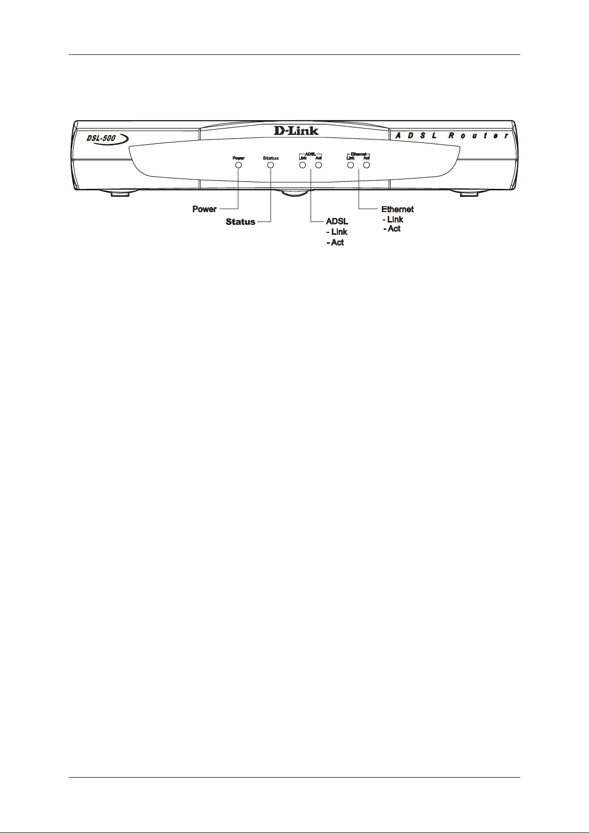
Front Panel
Place the Router in a location that permits an easy view of the LED indicators
shown in the front panel diagram below.
Figure 1-1 Front Panel
Rear Panel
The rear panel of the Router provides access to the AC power adapter cord
connection as well as the port connections.
Figure 1-2 Rear Panel
5
DSL-500 ADSL Router User’s Guide
LED Indicators
Figure 1-3 LED Indicators
The LED Indicators read as follows:
Power Steady green light indicates the unit is powered on.
Status Lights steady green during the ADSL negotiation phase. Once the
connection status has been settled, the light will blink green.
ADSL: Link Steady green light indicates a valid ADSL connection. This will
light after the ADSL negotiation process has been settled.
ADSL: Act Blinking green light indicates an active WAN session.
Ethernet: Link Steady green light indicates a valid Ethernet connection.
Ethernet: Act Blinking green indicates an active Ethernet session.
6

DSL-500 ADSL Router User’s Guide
2
Hardware Installation
This chapter discusses the various connections you will need to make in order to
use the Router.
When selecting the location for the Router, al low room to access the connections
on the rear panel. You will want to place the Router so that you will be able to
see the LED indicators on the front panel. Also, allow some space above the
Router for ventilation to avoid problems with overheating.
It may be convenient for you to place the Router near the PC you i ntend to use
for initial configuration of the Router. For initial configuration of the device, you
may need convenient access to the RS-232 serial port on the rear panel. The RS232 serial port is intended for use with text-based console management software
for the initial configuration and for out-of-band management of the Router.
Whether it is necessary to use an RS-232 console manager for first time set up
depends on how you allocate IP addresses on your network. Read Chapter 3, First
Time Set Up to help you decide how best to use the Router on your network.
Connect the Power
Insert the AC Power Adapter cord into the power receptacle located on the rear
panel of the Router and plug the adapter into a nearby power source. You should
see the Power LED indicator light up and remain lit.
Connect ADSL Line
Use the twisted-pair ADSL cable (standard telephone cable) included with the
Router to connect it to your telephone line. Plug one end of the cable into the
ADSL port (RJ-11 receptacle) on the rear panel of the Router and insert the other
end into the telephone wall jack. The ADSL cable links the Router to the ISP’s
wide area network (including the Internet).
The Router must undergo a negotiation process to establish the terms of the
ADSL connection. During this negotiation the Status LED will light a steady
green, after which it will blink. If the ADSL line is disconnected, it will repeat
this process.
Connect Ethernet LAN to Router
The Router may be connected to any 10BASE-T Ethernet LAN. Connection to an
Ethernet concentrating device such as a switch or hub should use standard
twisted-pair cable with RJ-45 connectors. The RJ-45 port on the Router is a
straight-through (MDI-II) connection. Follow standard Ethernet guidelines when
7
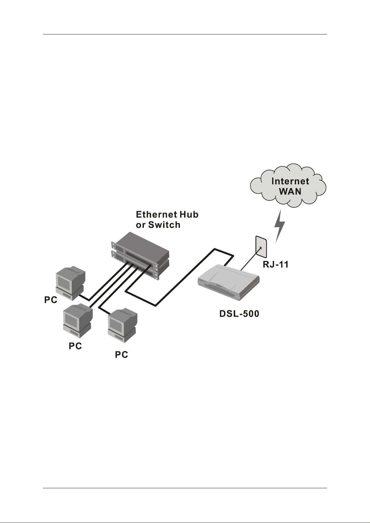
DSL-500 ADSL Router User’s Guide
deciding what type of cable to use to make this connection. Use a normal
straight-through cable when connecting the Router to a normal (MDI-X) port on a
switch or hub. Use a crossover cable when connecting it to an uplink (MDI-II)
port on a hub or switch or a cross over converter with a straight through cable.
When connecting the Router directly to a PC or server use a crossed cable. A
steady green Ethernet Link LED indicator will indicate a valid connection.
The rules governing Ethernet cable lengths apply to the LAN to Router
connection. Be sure that the cable connecting the Ethernet LAN to the Router
does not exceed 100 meters.
The diagram below illustrates a typical Ethernet LAN to Router connection.
Figure 2-1 LAN to Router Connection
8

DSL-500 ADSL Router User’s Guide
Connect Server or PC to Router
The Router may be connected directly to a server or PC using the RJ-45 Ethernet
port. The diagram below illustrates a PC/Server to Router connection with the
Router being employed as a firewall.
Figure 2-2 PC/Server to Router Connection
9

DSL-500 ADSL Router User’s Guide
3
Web Based Router Management
Introduction
The DSL-500 offers an embedded Web-based (HTML) interface allowing users to
manage the Router from anywhere on the network through a standard web
browser, such as Netscape Navigator/Communicator or Microsoft Internet
Explorer. The Web browser acts as a universal access tool and can communicate
directly with the Router using the HTTP protocol. Your web browser window may
vary with the screen captures (pictures) in this guide.
Note: This Web-based Management Module does not accept Chinese language
input (or other languages requiring 2 bytes per character).
Getting Started
The web-based manager requires a java enabled web browser to manage the
DSL-504. Web browsers such as the Netscape Communicator version 4 and above
or the Internet Explorer versions 4.0 and above are operable.
Setting up the PC
Now that the physical connection is complete, you need to set the TCP/IP settings for your
computer to properly connect to the DSL-500. Follow these simple steps.
Right-Click the “Network Neighborhood” (Win 98/98SE) or “My Network Places” (Win
ME/2000) icon on your desktop and select “Properties.”
10

DSL-500 ADSL Router User’s Guide
Highlight the line that reads “TCP/IP” and point to your installed Ethernet NIC.
Click “Properties.”
At this screen, select the IP Address tab.
Select “Obtain an IP Address Automatically.”
Click “OK.”
You will be prompted to reboot in Windows 98/98SE or ME
Click “Yes.”
For Windows 2000, restart your computer manually.
11
 Loading...