

Page 1

1
DP-313
Wireless Print Server
User’s Manual
Rev. 02 (August, 2001)
Page 2

2
TABLE OF CONTENTS
0 ABOUT THIS GUIDE..............................................................3
1 INTRODUCTION......................................................................4
Print Server Features ...............................................................4
External Features .....................................................................5
Port Connectors..................................................................6
Wireless DIP Switch ...............................................................6
Reset Button ...........................................................................7
DC Power Connector ...............................................................7
LED Indicators .......................................................................7
2 UNPACKING AND INSTALLATION.........................................9
Unpacking and Inspecting the Print Server ...............................9
Installing the Print Server ...................................................... 10
Power On Self-Test ................................................................. 12
Testing Your Print Server ....................................................... 14
3 CONTACTING TECHNICAL SUPPORT ................................16
4 PRODUCT SPECIFICATIONS ..............................................17
Printer Connection.................................................................. 17
Wireless Network Connection.................................................. 17
Network Protocols .................................................................. 18
Management and Diagnostics .................................................. 18
Environmental and Physical ................................................... 18
5 PORT PINOUTS..................................................................20
Parallel Ports.......................................................................... 20
6 LIMITED WARRANTY...................................................22
7 D-LINK OFFICES................................................................26
8 REGISTRATION CARD........................................................27
Page 3

3
0 ABOUT T HIS GUIDE
This manual describes the 3 Parallel Port Multi-protocol Wireless Print
Server, including a description of the print server’s features, as well as
the print server installation procedures and troubleshooting self-test
results.
For information about software configuration of the Print Server to
allow it to be used with your network, consult the PS Admin User’s
Guide included with your Print Server.
Page 4

4
1
1 INTRODUCTION
The Print Server is a compact wireless print server which connects
to your network through an access point under the infrastructure
mode or can be used in ad-hoc mode for direct communication
between PC/Notebook and print server anywhere you wish to locate
wireless printer services. It manages the flow of print files from your
workstations or file servers to its connected printers, delivering print
jobs to high-performance printers much faster than a file server or a
PC acting as a print server can.
Print Server Features
The Print Server improves network printing services in three ways:
♦ The Print Server picks up the workload of managing print file
traffic to its connected printers. This provides workload relief to
your file servers, and allows the file servers' full capacity to be used
for file access or other direct services to network users. On peerto-peer networks, workstations can print directly to the Print Server
without increasing the load of another workstation or server.
♦ The Print Server's parallel printer ports are IEEE 1284 compliant
high-speed bi-directional ports. High-speed laser printers connected
to the Print Server's parallel ports can be operated at their full
capacity.
♦ Because the Print Server is very portable and inexpensive
compared to a PC-based print server, and because the Print Server
Page 5

5
connects to your file servers through the network, printers can be
deployed to locations of maximum convenience to users.
The Print Server is best used with TCP/IP Protocol although NetBeui
and AppleTalk are also supported..
♦ TCP/IP
UNIX LPR/LPD (HP-UX, SunOS, Solaris, SCO, UnixWare, IBM
AIX)
Windows NT/2000, Windows 95/98/Me
NetWare 5.x NDPS LPR Remote Printing (TCP/IP)
♦ NetBEUI
Windows NT/2000, Windows 95/98/Me, Windows for Workgroups,
Microsoft LAN Manager, IBM LAN Server
♦ AppleTalk
MacOS EtherTalk
Windows-based setup and administration software, PS Admin, is
supplied with the Print Server, makin g configuration and management
quick and easy. The Print Server also supports configuration and
management via the telnet protocol for networks without Windowscompatible machines. A Web-base management interface is also
included.
External Features
This section describes the externally visible features of the DP313
Wireless Print Server.
Page 6
6
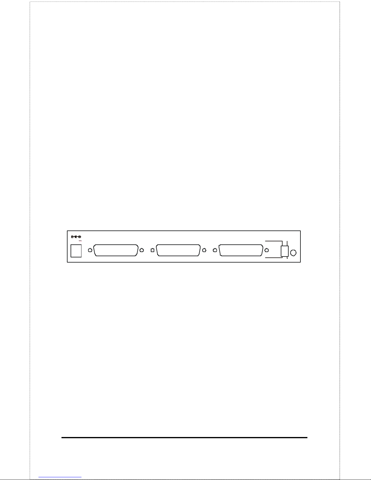
Port Connectors
The Print Server’s three printer ports are located on its rear panel.
Three identical parallel ports are labeled LPT1, LPT2 and LPT3.
These printer ports are independently configurable using the PS Admin
program or the print server’s telnet interface. (See the PS Admin
User’s Guide for information about configuring the print server’s )
The print server also supports web configuration permitting users to
configure settings through the web browser. DP-313 default IP
address as follows:
♦ Default IP address – 192.168.0.1
♦ Subnet Mask – 255.255.255.0
Note:-
The PC’s IP address must correspond with the print server’s IP
address in the same segment for the two devices to communicate.
Rear Panel
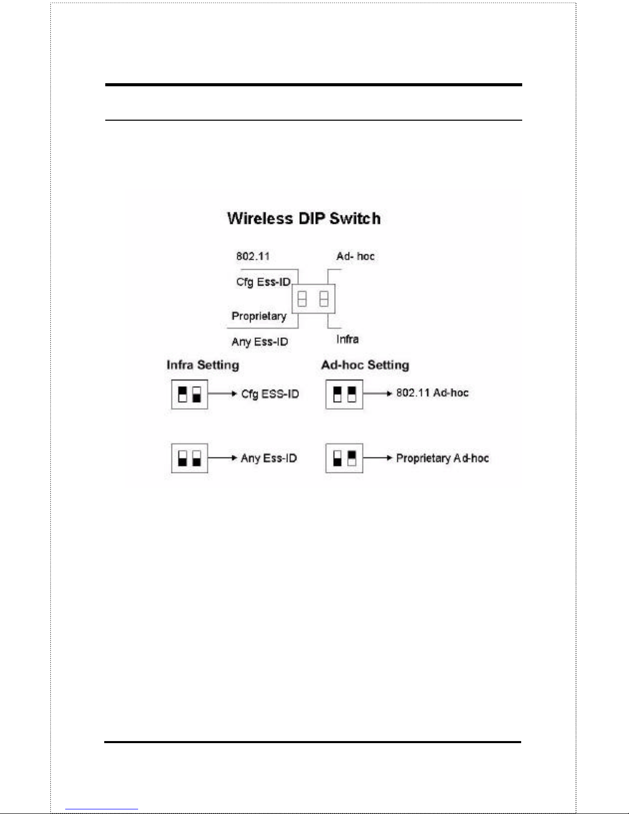
Wireless DIP Switch
The Print Server’s rear panel features a DIP switch allowing two
different modes of ad-hoc and infrastructure. In ad-hoc mode there
are 2 types of settings, 802.11 ad-hoc mode and Proprietary ad-hoc
mode where there is direct communication between PC/Notebook and
print server.
Under infrastructure mode there are 2 types of settings, Cfg ESS-ID
mode and Any ESS-ID mode where communication between
PC/Notebook and print server is through the Access Point acting as a
bridge between wired and wireless network.
LPT3 LPT2 LPT1
Reset
802.11 Ad hoc
Any ESS-ID Infra
DC 5V 2.4A
Cfg ESS-ID
ProPrietary
Page 7
7
Cfg ESS-ID (Configured ESS-ID)
• Connect to Access Point with ESS-ID
• Default ESS-ID is ‘default’
Any ESS-ID
• Connect to Access Point with any ESS-ID closest to the unit
Reset Button
Reset of the unit will be initiated when the reset button is pressed
once and then LEDs on LPT1, LPT2 & LPT3 begins to flash.
Factory Reset will be initiated when the reset button is pressed for
three seconds or when the LEDs on LPT1, LPT2 & LPT3 begins to
light up solid. Release the reset button and LPT1, LPT2, & LPT3
LEDs will begin to flash indicating the print server is changing to
factory reset. When factory reset is completed the print server’s
wireless setting will be set to default on channel 6 and ESS-ID is set as
‘default’.
DC Power Connector
The DC power input connector is located on the Print Server’s rear
panel and is labeled DC 5V.
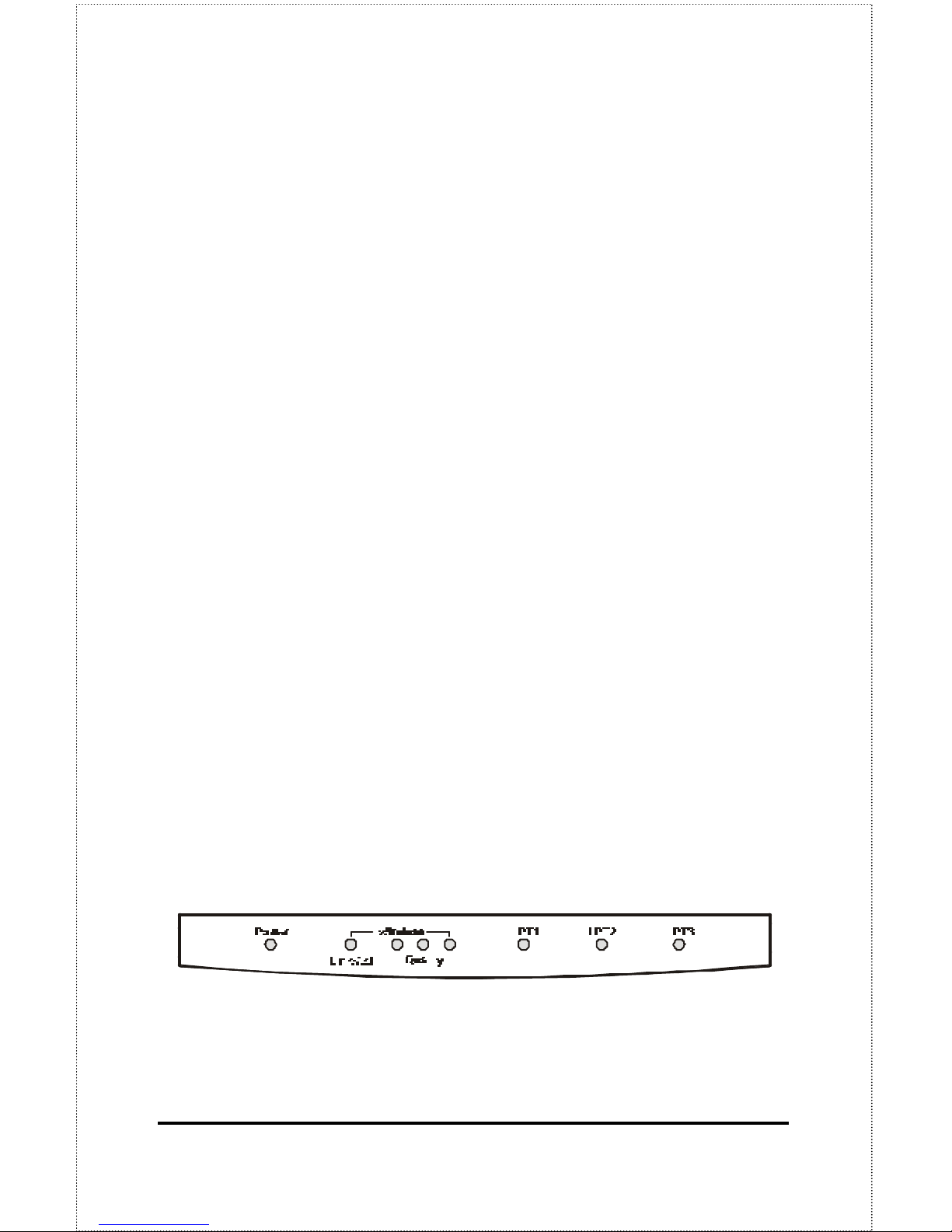
LED Indicators
The front panel of the Print Server features several LED indicators:
Front Panel LED Indicators
Page 8

8
♦ Power
◊ Steady green light confirms that the Print Server is powered
on.
♦ Link/Act
◊ In infrastructure mode steady or flashing green light confirms
the Print Server has a good connection to the Access Point.
◊ In ad-hoc mode steady or flashing green light confirms
connection to other PC/Notebook.
◊ The indicator blinks off briefly to indicate that the Print Server is
receiving/transmitting from/to the wireless network.
♦ Wireless Quality (3)
◊ These LED indicator lights show that the Print Server has
wireless quality connections to the network in either ad-hoc or
infrastructure mode.
◊ If only the first Wireless LED indicator lights up, it indicates
poor wireless quality connection.
◊ When the first & second LED indicator lights up simultaneously,
it indicates a moderate wireless quality connection.
◊ If all three LED indicators light up simultaneously, it shows a
high quality wireless connection.
♦ LPT1, LPT2, LPT3
◊ These LED indicators light to show that the Print Server is
transferring print data through the appropriate parallel port.
These three indicators are also used by the print server’s
power-on self test (POST) to indicate any hardware failures.
Page 9

9
2
2 UNPACKING AND
INSTALLATION
This chapter explains how to install your Print Server and connect it to
the network. It also describes the print server self diagnostics.
Unpacking and Inspecting the Print
Server
Carefully remove all items from the package. In addition to this
Hardware User’s Guide, be certain that you have:
♦ DP-313 Wireless Print Server
♦ Power Adapter
♦ User’s Manual
♦ Print Server Software
♦ Quick Installation Guide
If any item is missing, or if you find any damage or mismatch, promptly
contact your dealer for assistance.
Page 10

10
Installing the Print Server
WARNING: Configuration problems may result if the Print
Server is powered up without first
establishing its network connection. Follow
this procedure to avoid complications at the
configuration stage.
1. Confirm proper operation of each of the printers to be connected to the
Print Server.
2. When you have confirmed proper operation of each printer, switch its
power off.
3. Confirm that your wireless network is operating normally.
4. (a) Ad-Hoc Mode
u Before initiating set-up procedure for the print server make
sure your wireless PCMCIA card on your PC/Notebook is
set to channel 6 with ESS-ID set as ‘default’ in ad-hoc
mode.
u Make sure the DIP switch on the print server is positioned
in the ad-hoc mode.
u Press the Reset button on the print server for three seconds
until the LPT begins to light up initiating the factory reset.
u When factory reset is completed the print server will be set
to default on channel 6 and ESS-ID is set as ‘default’.
Note 1:
When changes are made on the print server’s wireless channel and
ESS-ID it must correspond to the PC/Notebook channel and ESS-ID
for direct wireless communication.
Note 2:
Page 11

11
The print server’s ad-hoc mode supports two modes (802.11 ad-hoc
mode and proprietary ad-hoc mode). You can position the DIP switch
on the print server to the mode you want to operate. Which option of
the ad-hoc mode is required depends on the operation of your print
server. It depends on which ad-hoc mode is supported by your
wireless card driver on the PC/Notebook. Some driver supports both
modes, however, some driver support only one of the modes. The
names of each ad-hoc mode may not be consistent between each
wireless card vendor therefore you may need to try each of the ad-hoc
mode (80.211 mode and proprietary mode) and select the mode that
can communicate with each other.
4. (b) Infrastructure Mode
u Before initiating set-up procedure for the print server make
sure your wireless PCMCIA card on your PC/Notebook is
set to channel 6 with ESS-ID set as ‘default’ in ad-hoc
mode.
u Make sure the DIP switch on the print server is positioned
in the ad-hoc mode.
u Press the Reset button on the print server for three seconds
until the LPT begins to light up initiating the factory reset.
u When factory reset is completed the print server will be set
to default on channel 6 and ESS-ID is set as ‘default’.
u Start-up PS Admin to modify the print server’s ESS-ID to
match with the Access Point’s ESS-ID and this will link the
print server to the Access Point. The ESS-ID uses
“default” as the factory setting.
u From the DIP switch on the print server alter to
infrastructure mode and the print server will reset.
Note 1:
Please make sure to change your PC/Notebook to infrastructure mode.
The ESS-ID on PC/Notebook and print server must match with the
Access Point’s ESS-ID.
Note 2:
Page 12

12
The print server supports two infrastructure operations (‘Cfg ESS-ID
mode and ‘Any ESS-ID’ mode).
‘Cfg ESS-ID’ mode: The print server will connect to the access
point that have the same ESS-ID with the print server’s configured
ESS-ID.
‘Any ESS-ID’ mode: The print server will connect to any access
point that print server finds first, however, the ESS-ID may not be the
same with each other. This is an easier way to connect to the access
point if you only have one access point, but be careful, it may connect
to your neighbor’s access point.
5. While each printer is powered off, install a printer cable to
connect its parallel port to the printer port of the Print Server.
6. Switch “ON” each connected printer.
7. Plug the AC power adapter’s DC output plug into the DC 5V
power socket on the rear panel of the Print Server.
8. Plug the power adapter into an electric service outlet. This will
supply power to the Print Server, as it has no external power
switch. The Power LED on the Print Server’s front panel
should light steady green, and the Print Server’s self-test will
proceed.
Power On Self-Test
When the Print Server is powered on, it automatically performs a self test on each of its major components. The final result of the self -test
is signaled by the state of the LPT1, LPT2, and LPT3 LED indicators
following the self -test. Preliminary to the actual component tests, the
three LED indicators are tested to confirm their steady and flashing
operation.
Page 13
13
Immediately after power-up, all of the LED’s should show steady
green for several seconds. Then the LPT1, LPT2, and LPT3 LEDs
should flash on simultaneously three times. Irregularity of any of the
three LEDs during these LED tests may mean there is a problem with
the LEDs themselves. Contact your dealer for correction of any LED
problems before proceeding.
The actual component tests immediately follow the LED tests. A
normal (no fault) result is signaled by a series of three cycles of
sequential flashing of the three LEDs, followed by a quiescent state
with all three LEDs dark.
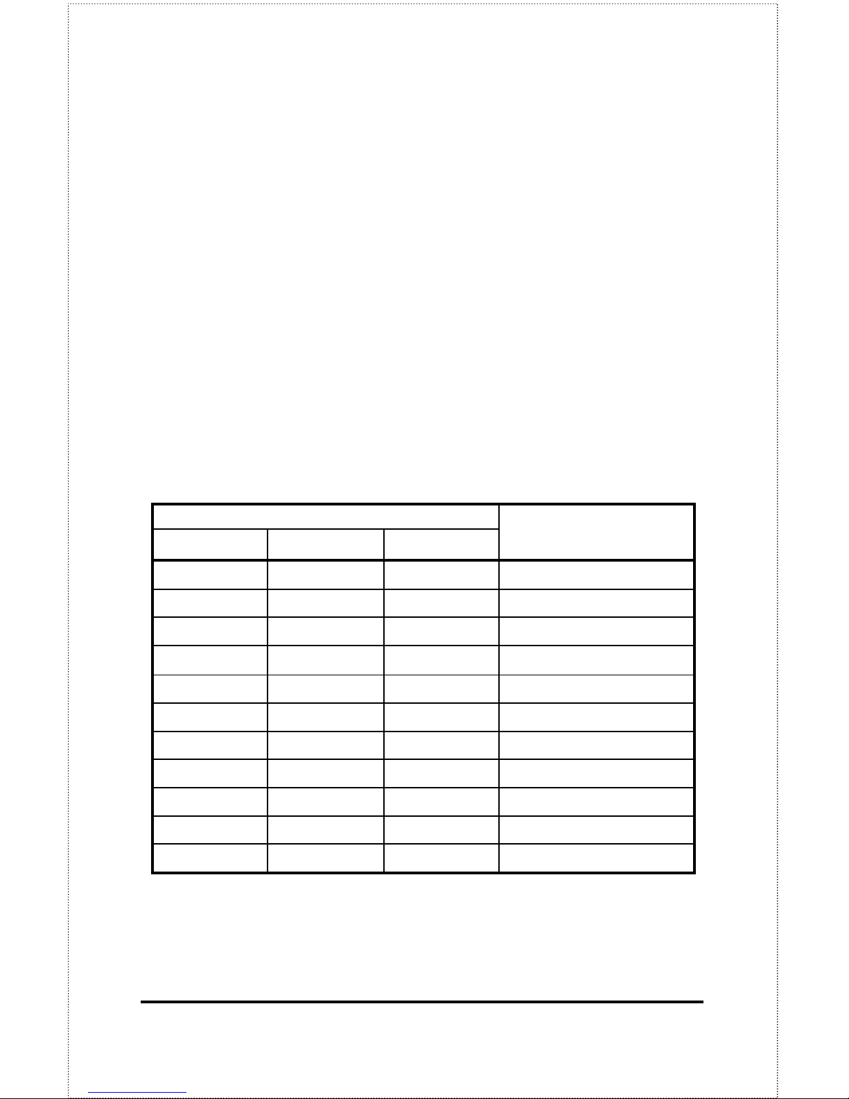
If the self-test routine traps any component error, then following the
LED tests the self-test will halt and the LED’s will contin uously signal
the error according to the following table. In the event of any such
error signal, contact your dealer for correction of the faulty unit.
LED Name
Faulty
LPT1 LPT2 LPT3
Component
Off off on/steady LPT3 error
Off off flashing Parallel-3 Controller error
Off on/steady off LPT2 error
Off flashing off
Parallel-2 Controller error
Off flashing flashing Flash Protected
on/steady off off LPT1 error
on/steady off on/steady Timer INT error
on/steady on/steady off RAM error
Flashing off off Parallel-1 Controller error
Flashing flashing off Flash erase/program error
Flashing flashing flashing Need to reload firmware
Page 14

14
Testing Your Print Server
The PS Admin software includes a Print Test function for confirmation
of printer cable connections and functions. That operational test can
be completed after you have installed the PS Admin software, and
have configured your Print Server and its ports. See the Testing Your
Print Server section of the PS Admin User’s Guide.
Page 15
15
DIP Switch Setting
Page 16

16
3 CONTACTING
T ECHNICAL SUPPORT
D-Link provides free technical support for customers within the United
States.
U.S. customers can contact D-Link technical support through our web
site,
e-mail, or by phone.
United States technical support is available Monday through Friday
from 6:00 a.m. to 6:00 p.m. (PST).
Web: http://www.dlink.com
Email: [email protected]
Phone: 949-788-0805 (option #4)
If you are a customer residing outside of the United States,
please refer to the list of D-Link locations that is included in
this manual.
Thank you for purchasing this product. We like to receive feedback
from our customers concerning our products. Please take a moment
to visit our web site. You can register your purchase on-line, learn
more about the newest networking products, and let us know the things
your new network has empowered you to do.
Page 17

17
A
4 P RODUCT
S PECIFICATIONS
Printer Connection
Standards: IEEE 1284 Bi-directional parallel interface
Ports: Bi-directional 25-pin parallel ports × 3
Parallel Port Bi-directional Communication: Hewlett-Packard
PJL (Printer Job Language) supported
Wireless Network Connection
Network Standards: Wireless LAN standard IEEE 802.11b
Network Data Transfer Rate: 11Mbps with fallback to 5.5Mbps,
2Mbps and 1Mbps.
Network Mode: Either Ad-hoc or Infrastructure mode.
Page 18

18
Network Protocols
Transport Protocols: TCP/IP, NetBEUI, AppleTalk/EtherTalk
TCP/IP Protocols Supported: BOOTP, SNMP, Telnet, TFTP, FTP,
LPD, RARP, DHCP
Management and Diagnostics
Standard: SNMP
MIBs: MIB-II (RFC 1213)
Diagnostic LED Indicators: Power, Link/Act, Wireless Quality
LPT1, LPT2, LPT3
Environmental and Physical
Power Supply: DC 5V 2.4A
Dimensions: 223.3mm × 131.7mm × 35mm
Weight: approx. 460g
Operating Temperature: 0 to 50°C
Storage Temperature: -25 to 55°C
Humidity: 5% to 95% non-condensing
Emissions: FCC Class A, CISPR 22 Class A, VCCI Class 1,
Page 19

19
Safety: UL (UL 1950), CSA (CSA950), TUV/GS (EN60950)
Page 20
20
B
5 P ORT PINOUTS
This appendix shows the pinouts of the Print Server parallel port
connector.
Parallel Ports
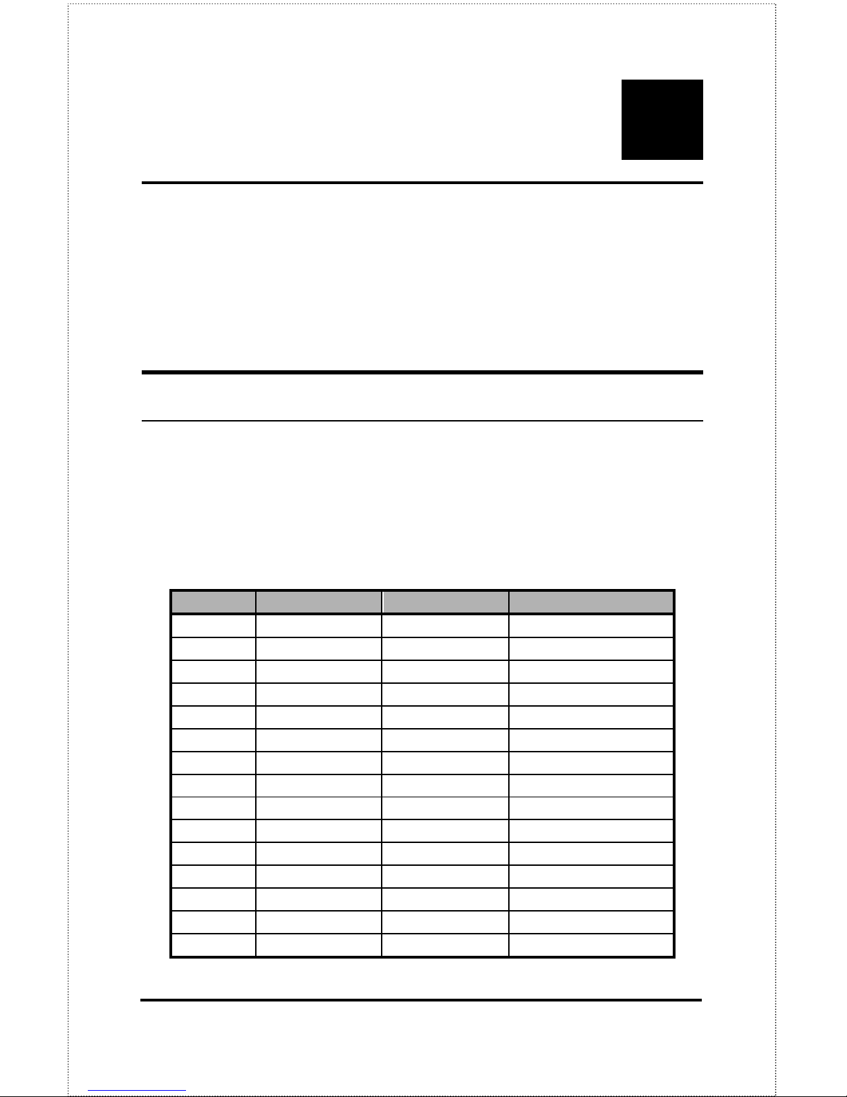
The following table lists the pinouts of the print server’s 25-pin
parallel port connector (identical to the connector used on most
personal computers), as well as the 36-pin Centronics connector used
on most printers.
Signal names beginning with n are active-low signals.
25-pin Centronics Signal Source
1 1 nStrobe Host
2 2 Data 1 Bi-directional
3 3 Data 2 Bi-directional
4 4 Data 3 Bi-directional
5 5 Data 4 Bi-directional
6 6 Data 5 Bi-directional
7 7 Data 6 Bi-directional
8 8 Data 7 Bi-directional
9 9 Data 8 Bi-directional
10 10 nAck Printer
11 11 Busy Printer
12 12 PError Printer
13 13 Select Printer
14 14 nAutoFd Host
15 32 nFault Printer
Page 21

21
25-pin Centronics Signal Source
16 31 nInit Host
17 36 nSelectIn Host
18-25 16, 17, 19-30 Ground
Page 22
22
6 LIMITED
WARRANTY
D-Link provides this limited warranty for its product only to the person or entity
who originally purchased the product from D-Link or its authorized reseller or
distributor.
Limited Hardware Warranty: D-Link warrants that the hardware portion of
the D-Link products described below (“Hardware”) will be free from material
defects in workmanship and materials from the date of original retail purchase
of the Hardware, for the period set forth below applicable to the product type
(“Warranty Period”) if the Hardware is used and serviced in accordance with
applicable documentation; provided that a completed Registration Card is
returned to an Authorized D-Link Service Office within ninety (90) days after
the date of original retail purchase of the Hardware. If a completed Registration
Card is not received by an authorized D-Link Service Office within such ninety
(90) period, then the Warranty Period shall be ninety (90) days from the date of
purchase.
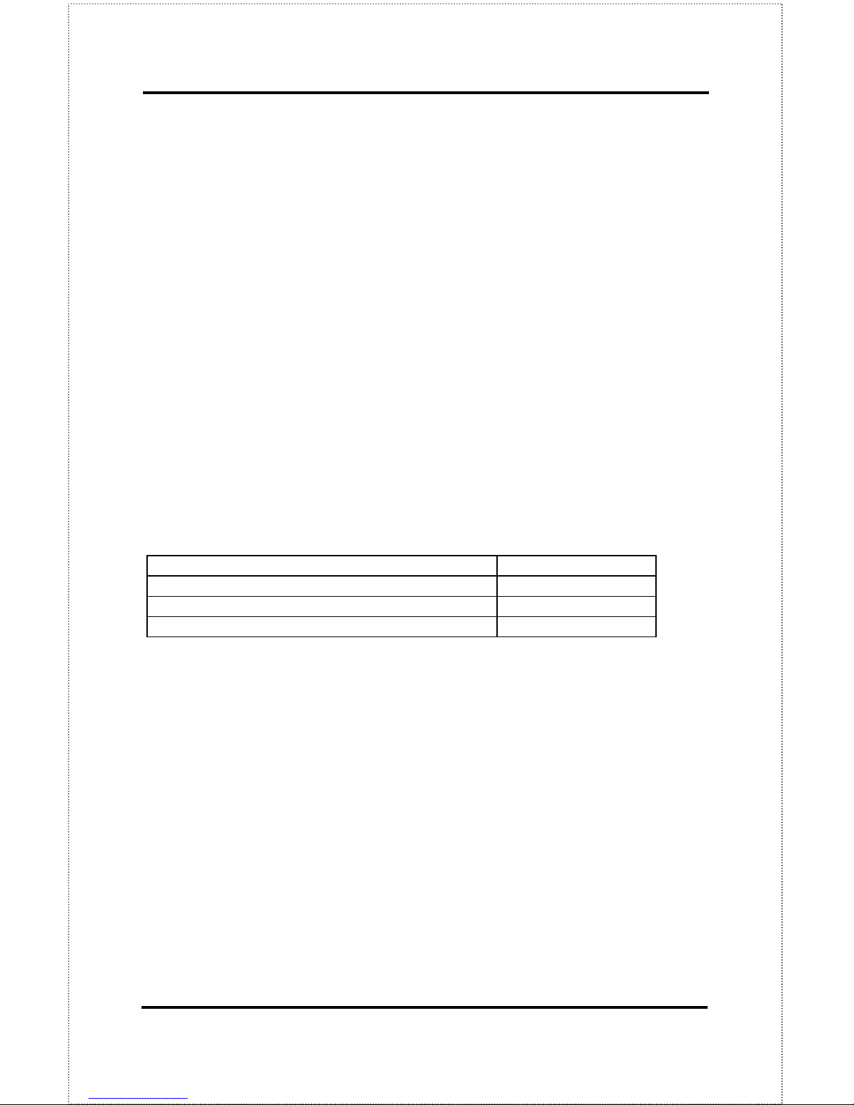
Product Type Warranty Period
Product (excluding power supplies and fans) One (1) Year
Power Supplies and Fans One (1) Year
Spare parts and spare kits Ninety (90) days
D-Link’s sole obligation shall be to repair or replace the defective Hardware at no
charge to the original owner. Such repair or replacement will be rendered by DLink at an Authorized D-Link Service Office. The replacement Hardware need
not be new or of an identical make, model or part; D-Link may in its discretion
may replace the defective Hardware (or any part thereof) with any reconditioned
product that D-Link reasonably determines is substantially equivalent (or
superior) in all material respects to the defective Hardware. The Warranty
Period shall extend for an additional ninety (90) days after any repaired or
replaced Hardware is delivered. If a material defect is incapable of correction, or
if D-Link determines in its sole discretion that it is not practical to repair or
replace the defective Hardware, the price paid by the original purchaser for the
defective Hardware will be refunded by D-Link upon return to D-Link of the
defective Hardware. All Hardware (or part thereof) that is replaced by D-Link,
or for which the purchase price is refunded, shall become the property of D-Link
upon replacement or refund.
Page 23

23
Limited Software Warranty: D-Link warrants that the software portion of the
product (“Software”) will substantially conform to D-Link’s then current
functional specifications for the Software, as set forth in the applicable
documentation, from the date of original delivery of the Software for a period of
ninety (90) days (“Warranty Period”), if the Software is properly installed on
approved hardware and operated as contemplated in its documentation. D-Link
further warrants that, during the Warranty Period, the magnetic media on
which D-Link delivers the Software will be free of physical defects. D-Link’s sole
obligation shall be to replace the non-conforming Software (or de fective media)
with software that substantially conforms to D-Link’s functional specifications
for the Software. Except as otherwise agreed by D-Link in writing, the
replacement Software is provided only to the original licensee, and is subject to
the terms and conditions of the license granted by D-Link for the Software. The
Warranty Period shall extend for an additional ninety (90) days after any
replacement Software is delivered. If a material non-conformance is incapable of
correction, or if D-Link determines in its sole discretion that it is not practical to
replace the non-conforming Software, the price paid by the original licensee for
the non-conforming Software will be refunded by D-Link; provided that the nonconforming Software (and all copies thereof) is first returned to D-Link. The
license granted respecting any Software for which a refund is given
automatically terminates.
What You Must Do For Warranty Service:
Registration Card. The Registration Card provided at the back of this manual
must be completed and returned to an Authorized D-Link Service Office for each
D-Link product within ninety (90) days after the product is purchased and/or
licensed. The addresses/telephone/fax list of the nearest Authorized D-Link
Service Office is provided in the back of this manual. FAILURE TO PROPERLY
COMPLETE AND TIMELY RETURN THE REGISTRATION CARD MAY
AFFECT THE WARRANTY FOR THIS PRODUCT.
Submitting A Claim . Any claim under this limited warranty must be submitted
in writing before the end of the Warranty Period to an Authorized D-Link
Service Office. The claim must include a written description of the Hardware
defect or Software nonconformance in sufficient detail to allow D-Link to
confirm the same. The original product owner must obtain a Return Material
Authorization (RMA) number from the Authorized D-Link Service Office and, if
requested, provide written proof of purchase of the product (such as a copy of
the dated purchase invoice for the product) before the warranty service is
provided. After an RMA number is issued, the defective product must be
packaged securely in the original or other suitable shipping package to ensure
that it will not be damaged in transit, and the RMA number must be prominently
marked on the outside of the package. Th e packaged product shall be insured
and shipped to D-Link, 53 Discovery Drive, Irvine CA 92618, with all shipping
costs prepaid. D-Link may reject or return any product that is not packaged and
Page 24

24
shipped in strict compliance with the foregoing requirements, or for which an
RMA number is not visible from the outside of the package. The product owner
agrees to pay D-Link’s reasonable handling and return shipping charges for any
product that is not packaged and shipped in accordance with the foregoing
requirements, or that is determined by D-Link not to be defective or nonconforming.
What Is Not Covered:
This limited warranty provided by D-Link does not cover:
Products that have been subjected to abuse, accident, alteration, modification,
tampering, negligence, misuse, faulty installation, lack of reasonable care, repair
or service in any way that is not contemplated in the documentation for the
product, or if the model or serial number has been altered, tampered with,
defaced or removed; Initial installation, installation and removal of the product
for repair, and shipping costs; Operational adjustments covered in the operating
manual for the product, and normal maintenance; Damage that occurs in
shipment, due to act of God, failures due to power surge, and cosmetic damage;
and Any hardware, software, firmware or other products or services provided by
anyone other than D-Link.
Disclaimer of Other Warranties: EXCEPT FOR THE LIMITED WARRANTY
SPECIFIED HEREIN, THE PRODUCT IS PROVIDED “AS-IS” WITHOUT ANY
WARRANTY OF ANY KIND INCLUDING, WITHOUT LIMITATION, ANY
WARRANTY OF MERCHANTABILITY, FITNESS FOR A PARTICULAR
PURPOSE AND NON-INFRINGEMENT. IF ANY IMPLIED WARRANTY
CANNOT BE DISCLAIMED IN ANY TERRITORY WHERE A PRODUCT IS
SOLD, THE DURATION OF SUCH IMPLIED WARRANTY SHALL BE LIMITED
TO NINETY (90) DAYS. EXCEPT AS EXPRESSLY COVERED UNDER THE
LIMITED WARRANTY PROVIDED HEREIN, THE ENTIRE RISK AS TO THE
QUALITY, SELECTION AND PERFORMANCE OF THE PRODUCT IS WITH
THE PURCHASER OF THE PRODUCT.
Limitation of Liability: TO THE MAXIMUM EXTENT PERMITTED BY LAW,
D-LINK IS NOT LIABLE UNDER ANY CONTRACT, NEGLIGENCE, STRICT
LIABILITY OR OTHER LEGAL OR EQUITABLE THEORY FOR ANY LOSS OF
USE OF THE PRODUCT, INCONVENIENCE OR DAMAGES OF ANY
CHARACTER, WHETHER DIRECT, SPECIAL, INCIDENTAL OR
CONSEQUENTIAL (INCLUDING, BUT NOT LIMITED TO, DAMAGES FOR
LOSS OF GOODWILL, WORK STOPPAGE, COMPUTER FAILURE OR
MALFUNCTION, LOSS OF INFORMATION OR DATA CONTAINED IN,
STORED ON, OR INTEGRATED WITH ANY PRODUCT RETURNED TO DLINK FOR WARRANTY SERVICE) RESULTING FROM THE USE OF THE
PRODUCT, RELATING TO WARRANTY SERVICE, OR ARISING OUT OF ANY
BREACH OF THIS LIMITED WARRANTY, EVEN IF D-LINK HAS BEEN
ADVISED OF THE POSSIBILITY OF SUCH DAMAGES. THE SOLE REMEDY
FOR A BREACH OF THE FOREGOING LIMITED WARRANTY IS REPAIR,
Page 25

25
REPLACEMENT OR REFUND OF THE DEFECTIVE OR NON-CONFORMING
PRODUCT.
Trademarks
Copyright 1999 D-Link Corporation. Contents subject to change
without prior notice. D-Link is a registered trademark of D-Link
Corporation/D-Link Systems, Inc. All other trademarks belong to
their respective proprietors.
Copyright Statement
No part of this publication may be reproduced in any form or by any means or
used to make any derivative such as translation, transformation, or adaptation
without permission from D-Link Corporation/D-Link Systems Inc., as stipulated
by the United States Copyright Act of 1976.
Page 26

26
7 D-L INK OFFICES
AUSTRALIA D-LINK AUSTRALASIA
Unit 16, 390 Eastern Valley Way, Roseville, NSW 2069, Australia
TEL: 61-2-9417-7100 FAX: 61-2-9417-1077
TOLL FREE: 1800-177-100 (Australia), 0800-900900 (New Zealand)
URL: www.dlink.com.au E-MAIL: [email protected], [email protected]
CANADA D-LINK CANADA
2180 Winston Park Drive, Oakville, Ontario L6H 5W1 Canada
TEL: 1-905-829-5033 FAX: 1-905-829-5095 BBS: 1-965-279-8732 FREE CALL: 1-800-354-6522
URL: www.dlink.ca E-MAIL: [email protected]
CHILE D-LINK SOUTH AMERICA
Isidora Goyenechea #2934 of.702, Las Condes, Santiago, Chile
TEL: 56-2-232-3185 FAX: 56-2-2320923 URL: www.dlink.cl
CHINA D-LINK CHINA
2F., Sigma Building, 49 Zhichun Road, Haidian District, 100080 Beijing, China
TEL: 86-10-88097777 FAX: 86-10-88096789
URL: www.dlink.com.cn
DENMARK D-LINK DENMARK
Naverland 2, DK-2600 Glostrup, Copenhagen, Denmark
TEL:45-43-969040 FAX:45-43-424347 URL: www.dlink.dk
E-MAIL: [email protected]
EGYPT D-LINK MIDDLE EAST
7 Assem Ebn Sabet Street, Heliopolis Cairo, Egypt
TEL: 202-2456176 FAX: 202-2456192 URL: www.dlink-me.com
E-MAIL: [email protected]
FRANCE D-LINK FRANCE
Le Florilege #2, Allee de la Fresnerie
78330 Fontenay Le Fleury France
TEL: 33-1-30238688 FAX: 33-1-3023-8689 URL: www.dlink-france.fr
E-MAIL: [email protected]
GERMANY D-LINK GERMANY
D-Link Central Europe / D-Link
Deutschland Gmbh
Schwalbacher Stra_e 74
65760 Eschbom
TEL: ++49-6196/7799-0 FAX: ++49-6196/7799-300
INDIA D-LINK INDIA
Plot No.5, Kurla-Bandra Complex Road,
Off Cst Road, Santacruz (E), Bombay - 400 098 India
TEL: 91-22-652-6696 FAX: 91-22-652-8914 URL: www.dlink-india.com
E-MAIL: [email protected]
ITALY D-LINK ITALIA
Via Nino Bonnet No. 6/b, 20154 Milano, Italy
TEL: 39-02-2900-0676 FAX: 39-02-2900-1723 URL: www.dlink.it
E-MAIL: [email protected]
JAPAN D-LINK JAPAN
10F, 8-8-15 Nishi-Gotanda, Shinagawa-ku, Tokyo 141 Japan
TEL: 81-3-5434-9678 FAX: 81-3-5434-9868 URL: www.d-link.co.jp
RUSSIA D-LINK RUSSIA
Michurinski Prospekt 49, 117607 Moscow, Russia
TEL: 7-095-737-3389, 7-095-737-3492 FAX: 7-095-737-3390
SINGAPORE D-LINK INTERNATIONAL
1 International Business Park, #03-12 The Synergy, Singapore 609917
TEL: 65-774-6233 FAX: 65-774-6322
URL: www.dlink-intl.com E-MAIL: [email protected]
S. AFRICA D-LINK SOUTH AFRICA
Unit 2, Parkside 86 Oak Avenue
Highveld Technopark Centurion, Gauteng, Republic of South Africa
TEL: 27(0)126652165 FAX: 27(0)126652186
SWEDEN D-LINK SWEDEN
P.O. Box 15036, S-167 15 Bromma Sweden
TEL: 46-(0)8564-61900 FAX: 46-(0)8564-61901 E-MAIL: [email protected]
URL: www.dlink.se
TAIWAN D-LINK TAIWAN
2F, No. 119 Pao-Chung Road, Hsin-Tien, Taipei, Taiwan, R.O.C.
TEL: 886-2-2910-2626 FAX: 886-2-2910-1515 URL: www.dlinktw.com.tw
U.K. D-LINK EUROPE
4th Floor, Merit House, Edgware Road, Colindale, London, NW9 5AB, U.K.
TEL: 44-20-8731-5555 FAX: 44-20-8731-5511
URL: www.dlink.co.uk E-MAIL: [email protected]
U.S.A. D-LINK U.S.A.
53 Discovery Drive, Irvine, CA 92618 USA
TEL: 1-949-788-0805 FAX: 1-949-753-7033 INFO LINE: 1-800-326-1688
BBS: 1-949-455-1779, 1-949-455-9616
Page 27
27
Register by mail or online at http://www.dlink.com/sales/reg/
8 REGISTRATION CARD
Print, type or use block letters.
Your name: Mr./Ms _____________________________________________________________________________
Organization: ________________________________________________ Dept. ____________________________
Your title at organization: ________________________________________________________________________
Telephone: _______________________________________ Fax:________________________________________
Organization's full address: ______________________________________________________________________
____________________________________________________________________________________________
Country: _____________________________________________________________________________________
Date of purchase (Month/Day/Year): _______________________________________________________________
Product Model Product Serial No. * Product installed in type of
computer (e.g., Compaq 486)
* Product installed in
computer serial No.
(* Applies to adapters only)
Product was purchased from:
Reseller's name: ______________________________________________________________________________
Telephone: _______________________________________ Fax:________________________________________
Reseller's full address: _________________________________________________________________________
_________________________________________________________________________
_________________________________________________________________________
Answers to the following questions help us to support your product:
1. Where and how will the product primarily be used?
oHome oOffice oTravel oCompany Business oHome Business oPersonal Use
2. How many employees work at installation site?
o1 employee o2-9 o10-49 o50-99 o100-499 o500-999 o1000 or more
3. What network protocol(s) does your organization use?
oXNS/IPX oTCP/IP oDECnet oOthers_____________________________
4. What network operating system(s) does your organization use?
oD-Link LANsmart oNovell NetWare oNetWare Lite oSCO Unix/Xenix oPC NFS o3Com 3+Open
oBanyan Vines oDECnet Pathwork oWindows NT oWindows NTAS oWindows '95
oOthers__________________________________________
5. What network management program does your organization use?
oD-View oHP OpenView/Windows oHP OpenView/Unix oSunNet Manager oNovell NMS
oNetView 6000 oOthers________________________________________
6. What network medium/media does your organization use ?
oFiber-optics oThick coax Ethernet oThin coax Ethernet o10BASE-T UTP/STP
o100BASE-TX o100BASE-T4 o100VGAnyLAN oOthers_________________
7. What applications are used on your network?
oDesktop publishing oSpreadsheet oWord processing oCAD/CAM
oDatabase management oAccounting oOthers_____________________
8. What category best describes your company?
oAerospace oEngineering oEducation oFinance oHospital oLegal oInsurance/Real Estate oManufacturing
oRetail/Chainstore/Wholesale oGovernment oTransportation/Utilities/Communication oVAR
oSystem house/company oOther________________________________
9. Would you recommend your D-Link product to a friend?
oYes oNo oDon't know yet
10.Your comments regarding this product?
__________________________________________________________________________________________
Page 28
28
__________________________________________________________________________________________
 Loading...