

Page 1

D-Link DKVM-IP8
8 Port KVM Switch
Over IP
V1.1
2013.4.10
Page 2

DKVM-IP8 User Manual
Certificates
FCC
This equipment has been tested and found to comply with the limits for a Class A digital
device, pursuant to Part 15 of the FCC. Operation is subject to the following two conditions:
(1) This device may not cause harmful interference
(2) This device must accept any interference received, including interference that may
cause undesired operation.
RoHS
All contents of this package, including products, packing materials and documentation
comply with RoHS.
2 / 104
Page 3

DKVM-IP8 User Manual
TABLE OF CONTENTS
1. The quick installation guide .............................................................................................. 6
1.1 Installation............................................................................................................... 6
1.2 Initial IP configuration ............................................................................................. 7
2. Introduction .................................................................................................................... 12
2.1 Feature overview .................................................................................................. 12
2.3 System requirement .............................................................................................. 14
2.4 When the server is up and running ....................................................................... 14
2.5 When the server is dead ....................................................................................... 14
3. Hardware installation ..................................................................................................... 16
3.1 Installation............................................................................................................. 16
3.2 Operations ............................................................................................................ 17
3.3 Hotkey Commands ............................................................................................... 18
3.4 OSD Operations ................................................................................................... 19
3.4.1 Login Windows ........................................................................................... 21
3.4.2 Port Name .................................................................................................. 22
3.4.3 Main Menu .................................................................................................. 23
3.4.4 Language .................................................................................................... 23
3.4.5 Port Name Edit ........................................................................................... 24
3.4.6 Port Search ................................................................................................. 24
3.4.7 User Security .............................................................................................. 25
3.4.8 Access List .................................................................................................. 26
3.4.9 Hotkey ........................................................................................................ 26
3.4.10 Time Settings ............................................................................................ 27
3.4.11 OSD Mouse .............................................................................................. 27
3.5 Firmware upgrade ................................................................................................. 28
4. IP module Configuration ................................................................................................ 30
4.1 Initial Configuration ............................................................................................... 30
4.1.1 Initial configuration via serial console ......................................................... 32
4.2 Keyboard, Mouse, and Video configuration .......................................................... 33
4.2.1 DKVM-IP8 keyboard settings ...................................................................... 33
4.2.2 Remote Mouse Settings ............................................................................. 33
4.2.3 Automatic mouse speed and mouse synchronization ................................. 34
4.2.4 Host system mouse settings ....................................................................... 34
4.2.5 Single and Double Mouse Mode ................................................................. 35
4.2.6 Recommended Mouse Settings .................................................................. 35
4.2.7 Video Modes ............................................................................................... 35
5. Usage ............................................................................................................................ 36
5.1 Prerequisites ......................................................................................................... 36
5.2 Login into the DKVM-IP8 and logout ..................................................................... 37
5.2.1 Login into the DKVM-IP8 ............................................................................ 37
3 / 104
Page 4

DKVM-IP8 User Manual
5.2.2 Logout from the DKVM-IP8 ......................................................................... 39
5.3 The Remote Console ............................................................................................ 39
5.4 Main Window ........................................................................................................ 40
5.4.1 Remote Console Control Bar ...................................................................... 41
5.4.2 Remote Console Status Line ...................................................................... 49
6. Menu Options ................................................................................................................ 50
6.1 Remote Control ..................................................................................................... 50
6.1.1 KVM Console .............................................................................................. 50
6.1.2 Telnet Console ............................................................................................ 50
6.2 Remote Power ...................................................................................................... 51
6.3 Mapping ................................................................................................................ 52
6.3.1 Floppy Disk ................................................................................................. 52
6.3.2 CD–ROM Image ......................................................................................... 53
6.3.3 Drive redirection ......................................................................................... 58
6.3.3.1 Driver Redirection Utility Installation ................................................. 59
6.3.3.2 Built-in Java Drive Redirection ......................................................... 63
6.3.4 Options ....................................................................................................... 65
6.4 User Management ................................................................................................ 66
6.4.1 Change Password ...................................................................................... 66
6.4.2 Users and Groups ...................................................................................... 66
6.5 KVM Settings ........................................................................................................ 68
6.5.1 User Console .............................................................................................. 68
6.5.2 Keyboard/Mouse ........................................................................................ 71
6.5.3 Video .......................................................................................................... 73
6.6 Device Settings ..................................................................................................... 74
6.6.1 Network ...................................................................................................... 74
6.6.2 Dynamic DNS ............................................................................................. 77
6.6.3 Security....................................................................................................... 79
6.6.4 Certificate ................................................................................................... 82
6.6.5 Authentication ............................................................................................. 85
6.6.6 Serial Port ................................................................................................... 86
6.6.7 Date / Time ................................................................................................. 88
6.6.8 Event Log ................................................................................................... 89
6.7 Tools ..................................................................................................................... 92
6.7.1 Device Information ...................................................................................... 92
6.7.2 Even log...................................................................................................... 93
6.7.3 Update Firmware ........................................................................................ 94
6.7.4 Unit Reset ................................................................................................... 95
7. Troubleshooting ............................................................................................................. 96
8. FAQs .............................................................................................................................. 97
9. Addendum ...................................................................................................................... 99
A. Key Codes .............................................................................................................. 99
B. Video Modes ........................................................................................................ 101
C. User Role Permissions ......................................................................................... 102
4 / 104
Page 5

DKVM-IP8 User Manual
D. DKVM-IP8 port table ............................................................................................ 102
E. Bandwidth Consumption ...................................................................................... 103
F. Cable diagrams ..................................................................................................... 104
5 / 104
Page 6
DKVM-IP8 User Manual
1. The quick installation guide
The DKVM-IP8 redirects local keyboard, mouse and video data to a remote administration
console. It allows you to control one or many computers locally at the server site or
remotely via the Internet using a standard browser. You can securely gain BIOS level
access to systems for maintenance, support, or failure recovery over the Internet.
Communication is secure via SSL encryption. Use in conjunction with a KVM switch for
mul
tiple-server access.
1.1 Installation
DKVM-IP8 switch redirects local keyboard, mouse and video data to a remote
administration console.
All data is transmitted via IP. DKVM-IP8 switch can be used inamulti administrator and
multi server environment as well. Besides, DKVM-IP8 switch is a KVM switch, which can
also be used withalocal console.
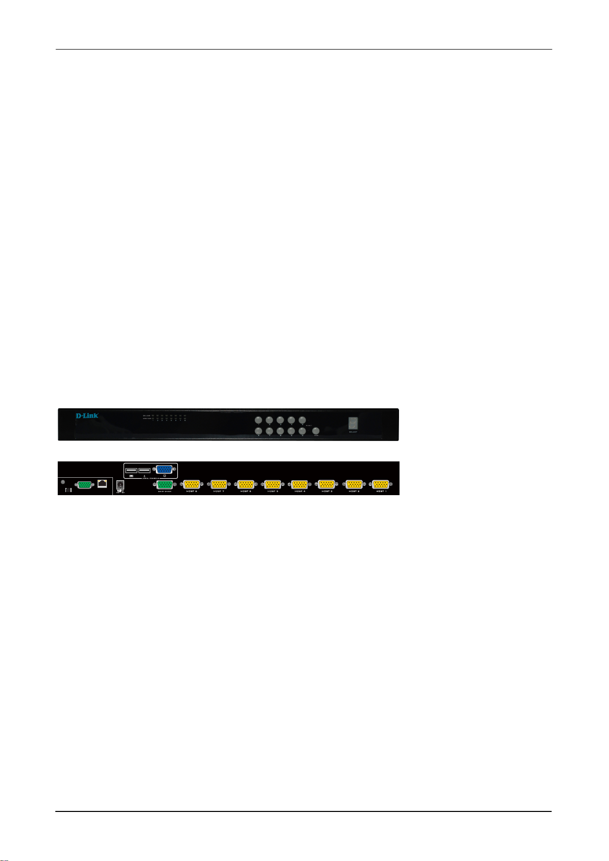
DKVM-IP8 switch hardware installation
Figure 1-1 The connectors of 8 port DKVM-IP8 switch front and rear side
Please perform the following steps:
1. (Optional) Connect the type A connector of USB A - Mini USB 5P cable to the host
computer, while
using remote mass storage control.
2. Connect Ethernet to LAN port and/or modem to serial port, depending on how you want
to access DKVM-IP8 switch
3. Power down your computer and DKVM-IP8 switch
4. Connect the power supply to DKVM-IP8 switch
5. Connect the monitor to the DKVM-IP8 swit
6. Connect the keyboard to the DKVM-IP8 switch console side.
7. Connect the mouse to the DKVM-IP8 switch console side.
8. Connect a VGA cable (15-pin HDDB Male / Male) with the Male side to both of the host
computer/KVM and the host port of the DKVM-IP8 switch.
9. Connect one purple end of 3-in-1 cable to the PS/2 mouse port on the host
computer/KVM, and the other end of 3-in-1 cable to the host PS/2 mouse port on the
DKVM-IP8 Switch.
ch console side.
6 / 104
Page 7

DKVM-IP8 User Manual
10. Connect one green end of 3-in-1 cable to PS/2 keyboard port on the host
computer/KVM, and the other end of 3-in-1 cable to the host PS/2 keyboard port on the
DKVM-IP8 switch.
11. (Optional) Connect the type A connector of USB A - mini USB 5P cable to the host
computer,
while using remote mass storage control.
12. Connect Ethernet to LAN port and/or modem to serial port, depending on how you want
to access DKVM-IP8 switch
13. Power on the computer.
1.2 Initial IP configuration
In factory default, DHCP mode is disabled (IP auto configuration = None), and the IP
settings are as below:
IP address 192.168.0.70
Subnet mask 255.255.255.0
Default Gateway None
If DHCP mode is enabled (IP auto configuration = DHCP), the DKVM-IP8 will try to
contact a DHCP server in the subnet to which it is physically connected. If a DHCP
server is found, it may provide a valid IP address, gateway address and net mask.
Before you connect the device to your local subnet, be sure to complete the
corresponding configuration of your DHCP server. It is recommended to configure a
fixed IP assignment to the MAC address of the DKVM-IP8 unit. You can find the MAC
address labeled on the bottom side of the metal housing.
7 / 104
Page 8
DKVM-IP8 User Manual
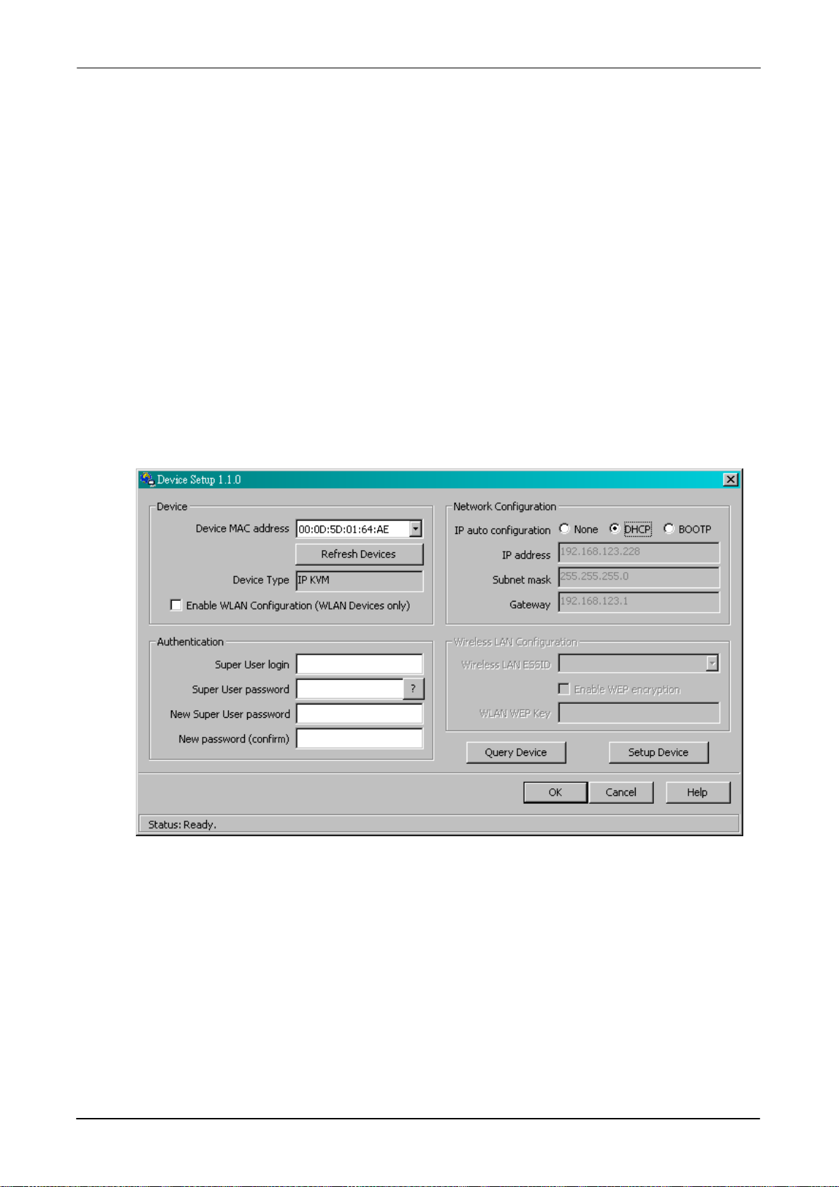
DKVM-IP8 Setup Tool
If this initial configuration does not meet your local requirements, use the setup tool to
change the configurations to your needs. The setup tool PSetup can be found on the
CD ROM delivered with this package. You can follow the procedures described below.
■ DHCP
If you have installed the DKVM-IP8 unit on a network that enables DHCP, you can
use the PSetup to find out the DKVM-IP8 unit’s I P.
(1) Plug Ethernet cable to DKVM-IP8 unit. DKVM-IP8 will get an IP via DHCP.
(2) Using PSetup (run PSetup.exe) to look for DKVM-IP8.
a. Select MAC address which label on bottom of DKVM-IP8 unit
b. Click Query Device
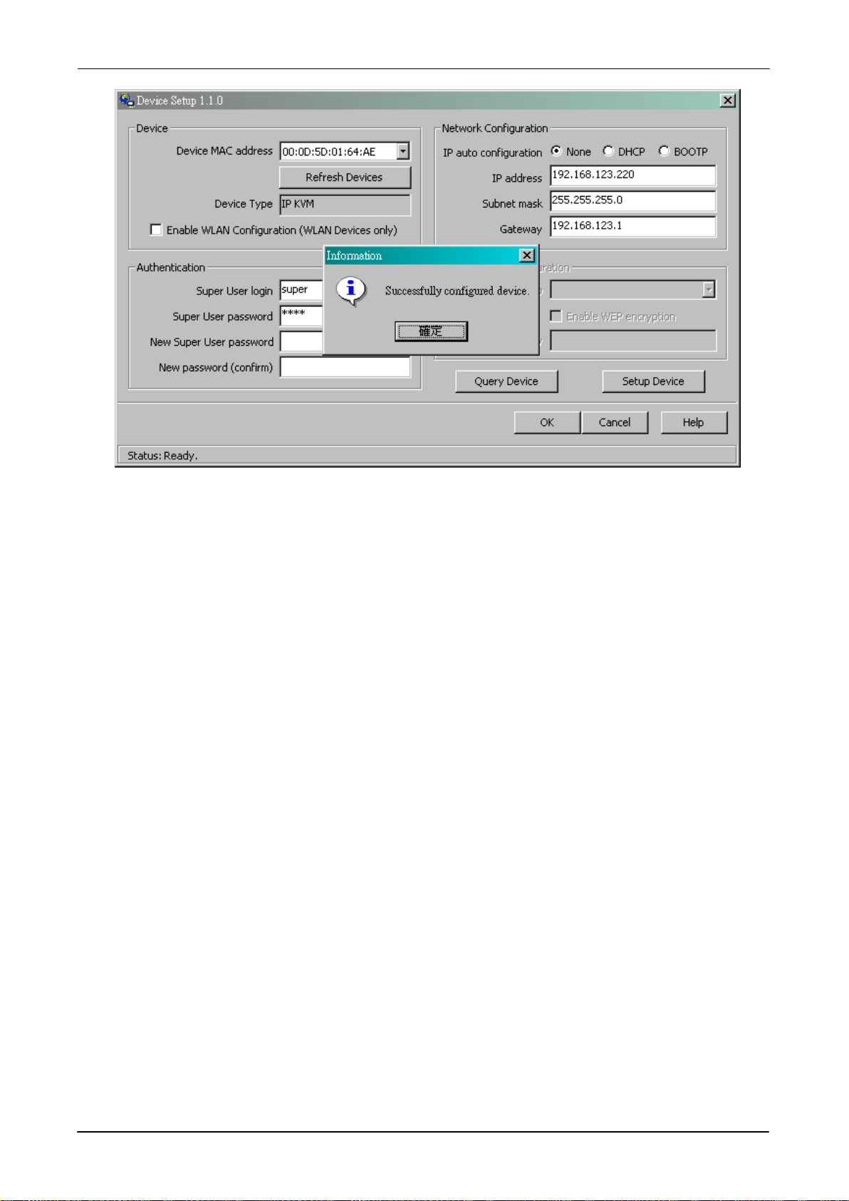
■ Setup the fixed IP
a. Setup “IP auto configuration” as “None” ; setup IP address and Subnet mask
b. Enter Super user login and password for Authentication (default : super/pass)
c. Click Setup Device. If super login was authenticated, it’ll show “Successfully
configured device”. Otherwise it’ll show “Permission Denied”.
8 / 104
Page 9
DKVM-IP8 User Manual
Install JVM on Client system
The DKVM-IP8 unit can be accessed with a standard JAVA enabled web browser. You must
install Java Runtime Environment: version 6 update 5 and above to your client system.
Note: At a minimum you must have IE7.0, IE8.0, Netscape7.0, Mozilla 3.2,
(Firefox 3.6) and above installed on your client computer.
Connect the DKVM-IP8 unit via Web Browser
Using the HTTP protocol or a secure encrypted connection via HTTPS and entering the IP
address of the DKVM-IP8 unit into your web browser to connect to the DKVM-IP8 unit.
This will lead you to the DKVM-IP8 login page as shown in figure below.
9 / 104
Page 10
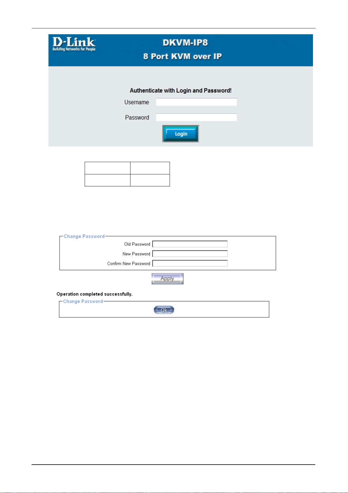
The factory default settings are:
Username admin
Password admin
DKVM-IP8 User Manual
The super user has all permissions to administrate your DKVM-IP8:
After login, the system will prompt for changing the default username and password to user specific settings.
Control servers via Remote Console
The Remote Console is the redirected screen, keyboard and mouse of the remote host
system. The Remote Console will behave exactly the same way as if you were sitting
directly in front of the screen of your remote system. That means that both the keyboard
and mouse can be used in the usual way. Open the console by selecting the preview
picture on the main site of the HTML front end. Figure 1-2 shows the top of the Remote
Console.
10 / 104
Page 11
DKVM-IP8 User Manual
Figure 1-2. Top part of the Remote Console
There are some options to choose from, and the important ones are the following:
Auto Adjust button
If the video displayed is of bad quality or distorted in some way, press this button and
wait a few seconds while DKVM-IP8 unit tries to adjust itself for the best possible
video quality.
Sync Mouse
Choose this option in order to synchronize the local with the remote mouse cursor.
This is especially necessary when using accelerated mouse settings on the host
system. In general there is no need to change mouse settings on the host.
Video Settings in Options Menu
This opens a new window with elements to control the DKVM-IP8 unit’s Video
Settings. You can change some values, for instance the brightness and contrast of
the picture displayed, which may improve the video quality. It is also possible to
revert to the default settings for all video modes or only the current one.
Note: At first start, if the local mouse pointer is not synchronized with the remote mouse
pointer, press the Auto Adjust Button once.
11 / 104
Page 12

DKVM-IP8 User Manual
2. Introduction
The KVM over IP technology (DKVM-IP8) combines digital remote KVM access via IP
networks with comprehensive and integrated system management. The DKVM-IP8 defines
a new class of remote KVM access devices that can save your money, time, space, and
equipment.
The DKVM-IP8 provides convenient, remote KVM access and control via LAN or Internet. It
captures, digitizes, and compresses video signal and transmits it with keyboard and mouse
signals to and from a remote computer. DKVM-IP8 provides a non-intrusive solution for
remote access and control. Remote access and control software runs on its embedded
processors only but not on mission-critical servers, so that there is no interference with
server operation or impact on network performance.
The DKVM-IP8 supports console of USB style keyboard, mouse, and HDDB15 video
interfaces. The DKVM-IP8 will automatically detect the current video mode of the console,
however manual fine-tuning is recommended to receive the best video quality.
2.1 Feature overview
♦ Manage servers around the world.
♦ KVM (keyboard, video, and mouse) access over IP and analogous telephone line
(modem needed)
♦ Full control under any OS, in BIOS mode, during boot, at Blue Screens
♦ No additional software necessary on servers
♦ Can be used with most standard KVM
♦ 256 bit SSL encryption of all transmitted data and Certificate management
♦ Automatically senses video resolution for best possible screen capture
♦ Serial over LAN, Remote serial power control via web
♦ Video Resolution up to:
Local console 1920 x 1440
Remote console 1600 x 1200, High-color depth 16 bits
♦ High-performance mouse tracking and synchronization
♦ Automatic adjustment of data rate to transmission line
♦ Drive redirection function on the remote console control bar, Remote mass storage
control.
♦ Can be controlled over all java-enabled Browsers
♦ Firmware update via web interface
♦ Port to connect a user console for direct analogous access to KVM switch
12 / 104
Page 13

2.2 Technical specifications
Function
Specification
KVM
IP
DKVM-IP8 User Manual
VGA Resolution Local : 1920 x 1440
Remote : 1600 x 1200
Daisy Chain
Connector DB15 (Female Type)
Support daisy chaining up to 8 layers
Flash port DC2.5F
Computer selection On Screen Display (OSD) Menu, Hotkey, Push Button
hotkey Provide various Hotkey (Scroll-Lock/ Caps-Lock/ Num-Lock/ Alt/
Ctrl/ Win)
Computer Port LEDs 2 color LED for each host port: ON LINE (Yellow), SATATION
(Red)
Power LED
Reset
Security
Indicating the KVM Switch is power on.
Press the “5” and “0” button simultaneously will restart the
firmware of the KVM switch.
Provide ACL (Access Control List) security function, store up to 8
independent ACL’s of controllable computer lists
Multilingual OSD
(On Screen Display)
Auto-Scan Intervals
OS supported
8 languages (English, France, Germen, Spanish, Italian,
Russian, Japanese, Simplified Chinese)
5 ~ 99 Sec.
Windows, Unix, Unix-like OS(Sun Solaris, Linux). Mac OSX
Browser supported Microsoft Internet Explorer version 6.0 or above, or
Netscape or Mozilla or Safari
Security
Authentication
IP filter
Local, LDAP, RADIUS
Network Connection 10/100 Ethernet
Telephone line (modem needed)
Management Interface Web , Utility, Telnet
Event log
NFS, SMTP, SNMP trap
Others
Housing Material Metal
DC Power Adapter 12V 1A
Operation Temperature 0 ~ 50 °C
Storage Temperature
Humidity 0~80%, Non-Condensing
Mechanical Rack mount, 1U
Dimension (mm) 444.5 x 190 x 44
-20 ~ 60 °C
13 / 104
Page 14

Item
Description
Item
Description
Local host side
No additional software necessary
Remote Console side
2.3 System requirement
Hardware
DKVM-IP8 User Manual
Local host side
Remote Console side Multiple PCs are linked into the network
Software
One PC or server or the console port of KVM switch unit
(1) Java Runtime Environment : version 6 update 5 and above.
Linux JDK 1_5_0_18 and above
(2) Browser: ( IE7.0 , IE8.0, Netscape7.0, Mozilla 3.2,
Firefox 3.6) and above.
2.4 When the server is up and running
The DKVM-IP8 gives you a full control over the remote server. The Management Console
allows you to access the remote server’s graphics, keyboard and mouse and to send
special commands to the server. You can also perform periodic maintenance of the server.
Using the Console Redirection Service, you are able to do the following:
I. Reboot the system
II. Watch the boot process.
III. Boot the system from a separate partition to load the diagnostic environment.
IV. Run special diagnostic programs.
2.5 When the server is dead
Obviously, fixing hardware defects is not possible through a remote management device.
Nevertheless DKVM-IP8 gives the administrator valuable information about the type of a
hardware failure. Serious hardware failures can be categorized into five different categories
with different chances to happen:
I. Hard disk failure 50%
II. Power cable detached, power supply failure 28%
III. CPU, Controller, main board failure 10%
IV. CPU fan failure 8%
V. RAM failure 4%
14 / 104
Page 15

DKVM-IP8 User Manual
Type of failure
Detected by
Using DKVM-IP8, administrators can determine which kind of serious hardware failure has
occurred (See table 2-1).
Hard disk failure Console screen, CMOS set-up information
Power cable detached, power supply
failure
Server remains in power off state after power
on command has been given.
CPU Controller, main board failure. Power supply is on, but there is no video
output.
CPU fan failure By server specific management software
RAM failure Boot-Sequence on boot console
Table 2-1. Host system failures and how they are detected.
15 / 104
Page 16
DKVM-IP8 User Manual
3. Hardware installation
3.1 Installation
You must have a 3-in-1 VGA cable for connecting KVM Switch to PS/2 computers, or a
2-in-1 VGA cable for connecting KVM Switch to USB computers.
The 3-in-1 VGA cable is a combo cable with one HDDB15 male connector at one end and
three connectors at the other.
The 2-in-1 VGA cable is a combo cable with one HDDB15 male connector at one end and
two connectors at the other.
Please perform the following steps:
1. (Optional) Connect the type A connector of USB A-Mini usb cable to the host computer,
while using remote mass storage control.
2. Connect Ethernet to LAN port and/or modem to serial port, depending on how you want
to access DKVM-IP8 switch
3. Power down your computer and DKVM-IP8 switch
4. Connect the power supply to DKVM-IP8 switch
5. Connect the monitor to the DKVM-IP8 switch console side.
6. Connect the keyboard to the DKVM-IP8 switch console side.
7. Connect the mouse to the DKVM-IP8 switch console side.
8. Connect a VGA cable (15-pin HDDB Male / Male) with the Male side to both of the host
computer/KVM and the host port of the DKVM-IP8 switch.
9. Connect one purple end of 3-in-1 cable to the PS/2 mouse port on the host
computer/KVM, and the other end of 3-in-1 cable to the host PS/2 mouse port on the
DKVM-IP8 Switch.
10. Connect one green end of 3-in-1 cable to PS/2 keyboard port on the host
computer/KVM, and the other end of 3-in-1 cable to the host PS/2 keyboard port on the
DKVM-IP8 switch.
11. (Optional) Connect the type A connector of USB A-mini usb cable to the host computer,
16 / 104
Page 17

DKVM-IP8 User Manual
while using remote mass storage control.
12. Connect Ethernet to LAN port and/or modem to serial port, depending on how you want
to access DKVM-IP8 switch
13. Power on the computer.
3.2 Operations
You can control the KVM Switch by three methods:
1. Using push buttons located on the front panel of the KVM Switch
2. Using the OSD (On-Screen Display)
3. Using hotkey commands through the console keyboard
It takes approximately 1-2 seconds for the video signal to refresh after switching servers
and re-synchronization of the mouse and keyboard signals. This is normal operation and
ensures that proper synchronization is performed at the console and the connected
servers.
When you power on KVM Switch, if the security function is enabled (default is disabled), it
will prompt a Login window waiting for you to enter the user name and password. You need
to pass the authentication to control the KVM Switch.
17 / 104
Page 18

DKVM-IP8 User Manual
3.3 Hotkey Commands
You can conveniently command KVM Switch via a simple hotkey sequence. To send
commands to KVM Switch, you must press the hotkey (default is Caps Lock) twice within 2
seconds. You will hear a beep sound confirming you are in the hotkey mode. If you do not
press any key during hotkey mode over 2 seconds the hotkey mode will be terminated and
back to normal state.
The default hotkey is Caps Lock but you can change hotkey as your application
convenience. If you prefer to use other hotkey, please go to OSD menu and change the
default hotkey to the other.
The table blow lists all the supported hotkey commands.
Command Function
Space Bar
or
1~8 Bank
01~08Port
Bring up the OSD screen
Move selection up or down
The first digit is bank number starting with “1”. The first KVM Switch
on the daisy chain line is bank 1 (the Master). A standalone KVM
Switch is fixed in bank 1. The second and the third digits indicate the
port number from 01 to 08.
PgUp
PgDn
Back to previous bank.
Go to next bank.
B To enable/disable beep sound function.
To enable/disable the Screen Saving function and 10min
L
auto-logout function. This default function is OFF.
To logi n to the OSD. If Security is enabled it will display the Login
P
window waiting for username and password. If Security is disabled it
will display the Status window.
For supervisor to reset the OSD back to factory default value
R
(except User Security settings).
S For supervisor to activate the Auto-scan function.
For supervisor to enable/disable Security function. If the Security is
U
off, you can access the KVM system without user name & password.
This default function is OFF.
18 / 104
Page 19

DKVM-IP8 User Manual
Item
Main Menu
Function
3.4 OSD Operations
You can either activate the OSD window by press hotkey or by mouse.
♦ By pressing hotkey: Press hotkey twice then press Space bar.
♦ By mouse: Press and hold the left button of the mouse and hit the Esc key to show the
Status screen. Press and hold the right button of the mouse and hit the Esc key to bring
up the Main Menu.
OSD Menu provides a menu-driven interface to control the KVM Switch. It has four types of
display screens:
1 Logi n Window: When powering on this KVM Switch, if the security function is enable,
it will prompt a login window and ask for user name and password. This KVM system
can setup one SUPERVISOR and eight USERs. SUPERVISOR can access to all OSD
functions. USER can access to PORT NAME and PORT SEARCH only.
2 Status screen: after the log in the Status screen will show up to display the current port
selection, port name, Hotkey type, and Screen Saving status.
3 Port Name: this menu displays port status, and allows us to switch bank/port. The Help
message is shown on the right pane of the OSD window.
4 M ain Menu: there are eight sub-menus to operate. They are listed as below:
01 LANGUAGE Select OSD language
02 PORT NAME EDIT Edit port name
03 PORT SEARCH Quick searching by port name
04 USER SECURITY Set username and password
05 ACCESS LIST Define user access authority
06 HOTKEY Select Hotkey
07 TIME SETTINGS Set auto-scan time interval
08 OSD MOUSE Modify OSD mouse speed
19 / 104
Page 20

DKVM-IP8 User Manual
+
+
=
+ + +
Caps
=
Caps
+
1 0
Example 1:
To bring up the OSD by hotkey, press “Caps Lock”, “Caps Lock” and the “Space Bar”.
Immediately, the OSD overlay screen will appear. The superimposed menu screen is
generated by the KVM Switch, and does not affect your computers or software function in
any way.
Caps
Lock
Caps
Lock
Space Bar
On Screen Display Menu
Example 2:
To switch to Bank 1 Port1, press “Caps Lock”, “Caps Lock”, and “1”, “0”, “1”.
Lock
Lock
1
Switch to Bank 1’s Port 1
Note. Every key needs to press within 2 seconds.
20 / 104
Page 21

DKVM-IP8 User Manual
P A S S W O R D
The selected BANK No.
The selected Port No.
The name of the Port
The selected Hotkey
Screen Saving enabled
3.4.1 Login Windows
Power on the local console monitor and power on the KVM Switch by plug in the power
adapter. If the Security function is enabled (default is disabled), the Login window will show
up waiting for user name and password.
U S E R N A M E
The default is SUPERVISOR and default user name is eight zeros “00000000”.
The default password is eight zeros “00000000”.
There are case-insensitive, while OSD display fixed in upper case.
After login or port switch by panel button, OSD or Hotkey, the Status screen will show up to
display the information of current settings -- one digit Bank No., two-digit Port No., Port
Name and current Hotkey settings. Pressing any key or clicking mouse button will let the
Status screen disappeared.
1 0 1 S Y S T E M 0 1
C a p s L o c k
Screen Saving Function
♦ The Screen Saving function can be enabled/disabled with the hotkey “L” and default
setting is OFF (disable).
♦ When the Screen Saving function is enabled, if no input from the console keyboard or
mouse over 10 minutes, the KVM Switch will turn off the screen display and auto-logout
and show up Login window asking for user name and password (if the security function
is disabled). One more minute of keyboard/mouse inactivity, the monitor will be turned
off (the monitor Power LED turns from green to orange).
♦ When the Screen Saving function is disabled, it will disable the 10min auto-logout
function as well.
Note: When Screen Saving enabled, the Login window will disappear if idle for
more then 1 minute. You Hit any key to bring up the Login window again.
21 / 104
Page 22

DKVM-IP8 User Manual
0 7 S Y S T E M 0 7 P g U p / P g D n :
W
OSD Function Key
Description
window.
PgDn
Go to next bank
The selected BANK
The selected port
Operation Hint
Indicating this port is connecting to a
Auto-scan
User
Firmware
3.4.2 Port Name
The first page shows the current port name, the selected port and the operation hint.
P O R T N A M E
B A N K : 1 F 1 : M E N U
0 1 S Y S T E M 0 1
0 2
S Y S T E M 0 2 F 3 : P R E V
∗
F 2 : L O G O U T
0 3 S Y S T E M 0 3 E S C : Q U I T
0 4 S Y S T E M 0 4 E N T E R : C O M P L E T E
0 5
S Y S T E M 0 5 / : S E L E C T
∗
0 6 S Y S T E M 0 6
0 8 S Y S T E M 0 8 B A N K S E L E C T
U S E R :
S U P E R V I S O R
S C A N T I M E :
1 0 S E C F
1 V 3
power on computer.
interval
Level
Version
F1 Go to the main menu
To login to the OSD. If Security is enabled it will display the
Login window waiting for entering username and
F2
password. If Security is disabled it will display the Status
F3 Go to previous menu
Enter Switch to the selected port
or Move up or down
PgUp Go to previous bank
Esc Exit
1 Show port 1 ~ 8
22 / 104
Page 23

DKVM-IP8 User Manual
M A I N M E N U
♦ USER: There are two types of user levels: SUPERVISOR (default) and USER.
SUPERVISOR can configure and change the OSD settings at main menu. USER can
only do the port switch and port search.
♦ SCAN TIME: This is the time interval for auto-scan function. When auto-scan function is
activated, KVM Switch will auto-scan the host port one by one according to the interval
setting. Note that the port without connecting to a computer/server will be skipped when
scanning.
♦ The numeric keypad is not supported, while in OSD screen, the arrow keys, PgUp, PgDn
and Enter keys are supported.
3.4.3 Main Menu
There are eight sub-menus under main menu for you to select.
S E L E C T O P T I O N :
0 1 L A N G U A G E
0 2 P O R T N A M E E D I T
0 3 P O R T S E A R C H
0 4 U S E R S E C U R I T Y
0 5 A C C E S S L I S T
0 6 H O T K E Y
0 7 T I M E S E T T I N G S
0 8 O S D M O U S E
3.4.4 Language
The OSD supports eight languages: English, French, German, Italian, Spanish, Simplified
Chinese, Japanese and Russian.
The default language is ENGLISH. Moving the cursor by keyboard (Up Arrow key “”or the
Down Arrow key “”) or mouse to select the language you need, and then press Enter key
to activate.
L A N G U A G E
C H O O S E A L A N G U A G E :
0 1 E N G L I S H
0 2 F R A N C H
0 3 G E R M A N
0 4 I T A L I A N
0 5 S P A N I S H
0 6 S I M P L I F I E D C H I N E S E
0 7 J A P A N E S E
0 8 R U S S I A N
23 / 104
Page 24

DKVM-IP8 User Manual
Note: The non-English languages on OSD are mainly for display, rather than
editing. For editing, no matter what language you select, OSD menu supports
English alphanumeric characters only. That means you can not edit the menu in
Japanese or Chinese.
3.4.5 Port Name Edit
You can edit the name for the selected port.
P O R T N A M E E D I T
B A N K 1 :
0 1 S Y S T E M 0 1
0 2 S Y S T E M 0 2
0 3 S Y S T E M 0 3
0 4 S Y S T E M 0 4
0 5 S Y S T E M 0 5
0 6 S Y S T E M 0 6
0 7 S Y S T E M 0 7
0 8 S Y S T E M 0 8
The first line bar is Bank number, following rows are port name list.
Use keyboard (Up Arrow key “”, Down Arrow key “”) or mouse to select the port you want
to edit. After select the port, you can either press the Enter Key, or move the cursor to port
name and click left button of mouse to switch the port immediately. Press PgUp key or
PgDn key for selecting the previous or next Bank.
Press Enter key to start editing. You can press Esc key to cancel the editing without any
change or press Enter key to save the modification.
3.4.6 Port Search
You can search a computer by the port name. Enter “*” and then press Enter key will show
all the port names.
P O R T S E A R C H
E N T E R N A M E :
24 / 104
Page 25

DKVM-IP8 User Manual
6
3.4.7 User Security
There are two levels of user security: SUPERVISOR and USER. You can configure one
SUPERVISOR and maximum eight USERs for the security.
U S E R S E C U R I T Y
N A M E P A S S W O R D
S 0 0 0 0 0 0 0 0 0 0 0 0 0 0 0 0
1
2
3
4
5
7
8
Press the Enter key or left button of mouse for editing. The left-top “S” indicates
SUPERVISOR, and the number 1 ~ 8 indicate USERs. The maximum length of NAME and
PASSWORD is eight characters (A~Z and 0~9).
Press Enter key to start editing. You can press Esc key to cancel the editing without any
change or press Enter key to save the modification.
Hint:
♦ Blank has an underscore while SPACE doesn't have.
♦ Press any alphanumeric key can move to the next input item. SPACE is treated
as a valid character.
♦ At default, all USER's username = SPACE and password = SPACE, but they are
invisible, so anyone can use SPACE to login to the OSD window.
25 / 104
Page 26

DKVM-IP8 User Manual
0 6 S Y S T E M 0 6 O O O O O O O O
Port No.
Port Name
Users
3.4.8 Access List
You can configure the access rights of each user.
A C C E S S L I S T X
B A N K : 1 1 2 3 4 5 6 7 8
0 1 S Y S T E M 0 1 O O O O O O O O
0 2 S Y S T E M 0 2 O O O O O O O O
0 3 S Y S T E M 0 3 O O O O O O O O
0 4 S Y S T E M 0 4 O O O O O O O O
0 5 S Y S T E M 0 5 O O O O O O O O
0 7 S Y S T E M 0 7 O O O O O O O O
0 8 S Y S T E M 0 8 O O O O O O O O
Only SUPERVISOR can configure the ACCESS LIST. The first block (the first two digits)
indicate the port number. The second block is the server/computer name list. The third
block (the last eight digits) is the access right of each user. Use the Enter key or left button
of mouse to active/deactivate the access right of each port. “X” indicates the access is
restricted and “O” indicates the access is permitted.
3.4.9 Hotkey
You can select the conventional key to be the hotkey.
H O T K E Y
S E L E C T H O T K E Y :
S c r o l l L o c k
N u m b e r L o c k
C a p s L o c k
L e f t C t r l
R i g h t C t r l
L e f t A l t
R i g h t A l t
L e f t W i N
R i g h t W i n
Some keyboard may not equip with all the special keys. Make sure the key you select is
available in you keyboard.
26 / 104
Page 27

DKVM-IP8 User Manual
M I D D L E
Note: If your keyboard does not support the selected hotkey, you can press the
right button of mouse and press the Esc key simultaneously to bring up the OSD
window.
3.4.10 Time Settings
You can configure the scan interval for auto-scan function.
T I M E S E T T I N H S
S C A N T I M E :
1 0 S E C
When the Auto-Scan function is activated, the KVM Switch will auto-scan the host ports one
by one according to the interval setting. Note that the port does not connect to a
computer/server will be skipped when scanning. The interval range is from 5 to 99 seconds.
Default interval is 10 seconds.
Press Enter key to start editing. You can press Esc key to cancel the editing without any
change or press Enter key to save the modification.
3.4.11 OSD Mouse
You can change the moving speed of mouse cursor in this sub-menu. There are three
levels of mouse cursor speed. The fastest moving speed is FAST, the second is MIDDLE
and the slowest is SLOW.
Using "" and "" key on keyboard to move highlight bar to the wished speed and the press
Enter key to confirm your selection.
O S D M O U S E
S E L E C T A P O I N T E R S P E E D :
F A S T
S L O W
27 / 104
Page 28

DKVM-IP8 User Manual
3.4 Firmware Upgrade
Please follow the following procedures:
1. Power on The KVM unit. Use 3-in-1 VGA Cable and PS/2 to USB Changer, The VGA
end connect to Port1, another end connect to PC USB port. Then press Hokey +
Hokey + F, appears “Beep” sound. At this time, The KVM console will have no
response.
2. The KVM now will be into upgade mode, waiting for firmware download.
3. Unplug the KVM mouse and Keyboard, Connect the mouse to the Computer directly,
Run “Firmware Upgrade Utility.exe”
3.4.1. Run Firmwar Upgrade Utility
5. Click Find device to Found device, and to select the FW upgrade file. Please make
sure you select the correct FW upgrade file .
3.4.2. Find Device
3.4.3. Select Firmware Upgrade firmware File
28 / 104
Page 29

DKVM-IP8 User Manual
6. Click upgade , start to upgrade. The upgrade process takes about 6-10 seconds, then
display Upgade OK and please reset your device if complete the upgrade
successfully.
3.4.4. Start to Upgrade
3.4.5. Firmware U pgrade finished
7. Now the KVM unit should be running on the new firmware. The FW version can be
seen on the bottom-right corner of the OSD window.
29 / 104
Page 30

DKVM-IP8 User Manual
4. IP module Configuration
4.1 Initial Configuration
If DHCP mode is enabled (IP auto configuration = DHCP), the DKVM-IP8 will try to
contact a DHCP server in the subnet to which it is physically connected. If a DHCP
server is found, it may provide a valid IP address, gateway address and net mask.
Before you connect the device to your local subnet, be sure to complete the
corresponding configuration of your DHCP server. It is recommended to configure a
fixed IP assignment to the MAC address of the DKVM-IP8. You can find the MAC
address labeled on the bottom side of the metal housing.
If DHCP mode is disabled (IP auto configuration = None), the factory default IP
settings are as below:
IP address 192.168.0.70
Subnet mask 255.255.255.0
Default Gateway None
Table 4-1 Initial Network Configurations
DKVM-IP8 Setup Tool
If this initial configuration does not meet your local requirements, use the setup tool to
change the configurations to your needs. The setup tool PSetup can be found on the
CD ROM delivered with this package. You can follow the procedures described below.
■ DHCP
If you have installed the DKVM-IP8 on a network that enables DHCP, you can use
the PSetup to find out the DKVM-IP8’s I P.
(1) Plug Ethernet cable to DKVM-IP8. DKVM-IP8 will get an IP via DHCP.
(2) Using PSetup (run PSetup.exe) to look for DKVM-IP8.
a. Select MAC address which label on bottom of DKVM-IP8
b. Click Query Device
Notes:
BOOTP, a static configuration protocol, uses a table that maps IP
addresses to physical addresses.
DHCP, an extension to BOOTP that dynamically assigns configuration
information. DHCP is backward compatible with BOOTP.
30 / 104
Page 31

DKVM-IP8 User Manual
■ Setup fixed IP
a. Setup “IP auto configuration” as “None” ; setup IP address, Subnet mask and gateway
b. Enter Super user login and password for Authentication (default : admin/admin)
c. Click Setup Device. If super login was authenticated, it’ll show “Successfully
configured device”. Otherwise it’ll show “Permission Denied”.
31 / 104
Page 32

DKVM-IP8 User Manual
Parameter
Value
Authentication
To adjust the authentication settings, enter your login as a super user, and change
your password.
Super user login
Enter the login name of the super user. The initial value is “super”. All characters
are in lower case.
Super user password
Enter the current password for the super user. This initial value is “pass”. All
characters are in lower case.
New super user password
Enter the new password for the super user.
New password (confirm)
Re-type the new password for the super user for confirmation.
To close the window and accept the changes, press the “OK” button; otherwise
press the “Cancel” button.
4.1.1 Initial configuration via serial console
For using serial terminal, the DKVM-IP8 has a serial line interface (host side). This
connector is compliant with the RS-232 serial line standard. The serial line has to be
configured with the parameters given in Table 4-2.
When configuring with a serial terminal, e.g., Hyper Terminal, reset the DKVM-IP8 and
immediately press the “ESC” key. You will see some device information, and a “=>”
prompt. Enter “config”, press “Enter” key and wait for a few seconds for the
configuration questions to appear.
Bits/second 115200
Data bits 8
Parity No
Stop bits 1
Flow Control None
Table 4-2. Serial line parameters
As you proceed, the following questions will appear on the screen. To accept the
default values shown in square brackets below, press “Enter” key.
IP auto configuration (none/dhcp/bootp):
IP [192.168.1.22]:
Net mask [255.255.255.0]:
Gateway (0.0.0.0 for none) [0.0.0.0]:
32 / 104
Page 33

DKVM-IP8 User Manual
IP auto-configuration
With this option, you can specify whether the DKVM-IP8 should get its network
settings from a DHCP or BOOTP server. For DHCP, enter “dhcp”, and for BOOTP
enter “bootp”. If you do not specify any of these, the IP auto-configuration is
disabled and subsequently you will be asked for the following network settings.
IP address
The IP address the DKVM-IP8. This option is only available if IP auto-configuration
is disabled.
Net mask
The net mask of the connected IP subnet. This option is only available if IP
auto-configuration is disabled.
Gateway address
The IP address of the default router for the connected IP subnet. If you do not have
a default router, enter 0.0.0.0. This option is only available if IP auto-configuration is
disabled.
4.2 Keyboard, Mouse, and Video configuration
Between the DKVM-IP8 and the host, there are two interfaces available for
transmitting keyboard and mouse data: USB and PS/2. The correct operation of the
remote mouse depends on several settings which will be discussed in the following
subsections.
4.2.1 DKVM-IP8 keyboard settings
The DKVM-IP8 settings for the host's keyboard type have to be corrected in order to
make the remote keyboard work properly. Check the settings in the DKVM-IP8 Web
front-end. See section 6.5.2 for details.
4.2.2 Remote Mouse Settings
A common seen problem with KVM devices is the synchronization between the local
and remote mouse cursors. The DKVM-IP8 addresses this situation with an intelligent
synchronization algorithm. There are two mouse modes available on the DKVM-IP8:
Auto mouse speed
The automatic mouse speed mode tries to detect the speed and acceleration
settings of the host system automatically. See the section below for a more
detailed explanation.
Fixed mouse speed
This mode just translates the mouse movements from the Remote Console in a
way that one pixel move will result in n-pixel moves on the remote system. This
33 / 104
Page 34

DKVM-IP8 User Manual
parameter n is adjustable with the scaling. Please note that this works only when
mouse acceleration is turned off on the remote system.
4.2.3 Automatic mouse speed and mouse synchronization
The automatic mouse speed mode performs the speed detection during mouse
synchronization. Whenever the local and remote mouse cursors move synchronously
or not, there are two ways for re-synchronizing local and remote mouse cursors:
Fast Sync
The fast synchronization is used to correct a temporary, but fixed skew. Choose
the option using the Remote Console options menu or press the mouse
synchronization hotkey sequence in case you defined one.
Intelligent Sync
If the fast sync does not work or the mouse settings have been changed on the
host system, use the intelligent resynchronization. This method takes more time
than the fast one and can be accessed with the appropriate item in the Remote
Console option menu. The intelligent synchronization requires a correctly
adjusted picture. Use the auto adjustment function to setup the picture, and make
sure that there are no window at the top left corner of the remote desktop that are
able to change the mouse cursor shape from the normal state. The Sync mouse
button on top of the Remote Console can behave differently, depending on the
current state of mouse synchronization. Usually pressing this button leads to a
fast sync, except in situations where the KVM port or the video mode changed
recently.
Note: At first start, if the local mouse pointer is not synchronized with
the remote mouse pointer, press the Auto Adjust Button once.
4.2.4 Host system mouse settings
The host's operating system knows various settings from the mouse driver.
Warning
The following limitations do not apply in case of USB and Mouse Type
“Windows >= 2000, MacOSX”.
While the DKVM-IP8 works with accelerated mice and is able to synchronize the local
with the remote mouse pointer, there are the following limitations, which may prevent
this synchronization from working properly:
Special Mouse Driver
There are mouse drivers that influence the synchronization process and lead to
desynchronized mouse pointers. If this happens, make sure you do not use a
special vendor-specific mouse driver on your host system.
34 / 104
Page 35

DKVM-IP8 User Manual
Windows XP Mouse Settings
Windows XP knows a setting named “improve mouse acceleration”, which has to
be deactivated.
Active Desktop
If the Active Desktop feature of Microsoft Windows is enabled do not use a plain
background. Instead, use some kind of wallpaper. As an alternative, you could
also disable the Active Desktop completely.
Navigate your mouse pointer into the upper left corner of the applet screen and
move it slightly forth and back. Thus the mouse will be resynchronized. If
re-synchronizing fails, disable the mouse acceleration and repeat the procedure.
4.2.5 Single and Double Mouse Mode
The information above applies to the Double Mouse Mode, where remote and local
mouse pointers are visible and need to be synchronized. The DKVM-IP8 also
features another mode, the Single Mouse Mode, where only the remote mouse
pointer is visible. Activate this mode in the open Remote Console and click into the
window area. The local mouse pointer will be hidden and the remote one can be
controlled directly. To leave this mode, it is necessary to define a mouse hotkey in the
Remote Console Settings Panel. Press this key to free the captured local mouse
pointer.
4.2.6 Recommended Mouse Settings
For the different operating systems we can give the following advice:
MS Windows 2000/2003 (Professional and Server) and XP (all versions)
In general, we recommend the usage of a mouse via USB. Choose USB without
Mouse Sync. For a PS/2 mouse choose Auto Mouse Speed. For XP disable the option
“enhance pointer precision” in the Control Panel.
SUN Solaris
Adjust the mouse settings either via xset m 1 or use the CDE Control Panel to set the
mouse to “1:1, no acceleration”. As an alternative you may also use the Single Mouse
Mode.
MAC OS X
We recommend using the Single Mouse Mode.
4.2.7 Video Modes
The DKVM-IP8 recognizes a limited number of common video modes. When running
X11 on the host system, please do not use any custom mode lines with special video
modes. If you do, the DKVM-IP8 may not be able to detect them. We recommend
using any of the standard VESA video modes, instead.
35 / 104
Page 36

DKVM-IP8 User Manual
5. Usage
5.1 Prerequisites
The DKVM-IP8 features an embedded operating system and applications offering a variety
of standardized interfaces. This chapter will describe both these interfaces, and the way to
use them in a more detailed manner. The interfaces are accessed using the TCP/IP
protocol family, thus they can be accessed using the LAN port of the device.
The following interfaces are supported:
HTTP/HTTPS
Full access is provided by the embedded web server. The DKVM-IP8 environment can
be entirely managed using a standard web browser. You can access the DKVM-IP8
using the insecure HTTP protocol, or using the encrypted HTTPS protocol. Whenever
possible, use HTTPS.
Telnet
A standard Telnet client can be used to access an arbitrary device connected to the
DKVM-IP8's serial port via a terminal mode.
The primary interface of the DKVM-IP8 is the HTTP interface. This is covered
extensively in this chapter. Other interfaces are addressed in subtopics.
In order to use the Remote Console window of your managed host system, the browser
has to come with a Java Runtime Environment version 1.4.2 or above. If the browser has
no Java support (such as on a small handheld device), you are still able to maintain your
DKVM-IP8 using the administration forms displayed by the browser itself.
For an insecure connection to the DKVM-IP8, we can recommend the following browsers:
• Microsoft Internet Explorer version 6.0 or higher on Windows 2000 and Windows XP
• Netscape Navigator 7.0 or Mozilla 1.6 on Windows 2000, Windows XP, Unix, Linux and
UNIX-like Operating Systems
In order to access the remote host system using a securely encrypted connection, you
need a browser that supports the HTTPS protocol. Strong security is only assured by using
a key length of 256 Bit. Some of the old browsers do not have a strong 256 Bit encryption
algorithm.
Using the Internet Explorer, open the menu entry “?” and “Info” to read about the key
length that is currently activated. The dialog box contains a link that leads you to
information on how to upgrade your browser to a state of the art encryption scheme.
Figure 5-1 shows the dialog box presented by the Internet Explorer 6.0.
36 / 104
Page 37

DKVM-IP8 User Manual
Figure 5-1. The Internet Explorer displaying the encryption key length
Newer web browsers generally support strong encryption on default.
5.2 Login into the DKVM-IP8 and logout
5.2.1 Login into the DKVM-IP8
Launch your web browser. Direct it to the address of your DKVM-IP8, which you
configured during the installation process. The address used might be an IP address or
a domain name, in the case where you have given your DKVM-IP8 a symbolic name in
the DNS. For instance, type the following in the URL field of your browser when
establishing an unsecured connection:
http://<IP address of DKVM-IP8>
When using a secure connection, type in:
https://<IP address of DKVM-IP8>
This will lead you to the DKVM-IP8 login page as shown in Figure 5-2.
Figure 5-2. Login screen
The DKVM-IP8 has a built-in super user that has all permissions to administrate your
DKVM-IP8:
Username admin (factory default)
Password admin (factory default)
Table 5-1. Standard user settings
37 / 104
Page 38

DKVM-IP8 User Manual
Warning
The user “super” is not allowed to login via the serial interface of the
DKVM-IP8.
Warning
Please make sure to change the super user password immediately after you
have installed and accessed your DKVM-IP8 for the first time. Unchanging of
the password for the super user is a severe security risk and might result in
unauthorized access to the DKVM-IP8 and to the host system including all
possible consequences!
Warning
Your web browser has to accept cookies, or else login is not possible.
Navigation
Having logged into the DKVM-IP8 successfully, the main page of the DKVM-IP8
appears (see Figure 5-3). This page consists of three parts; each of them contains
specific information. The buttons on the upper side allow you to navigate within the
front end (see Table 5-2 for details). Within the right frame, task-specific information is
displayed that depends on the section you have chosen before.
Figure 5-3. Main page
38 / 104
Page 39

DKVM-IP8 User Manual
Return to the main page of the DKVM-IP8 .
Open the DKVM-IP8 remote console.
Exit from the DKVM-IP8 front end.
Warning
If there is no activity for 30 minutes, the DKVM-IP8 will log you out,
Table 5-2. Buttons from the front end
automatically. A click on one of the links will bring you back to the login screen.
5.2.2 Logout from the DKVM-IP8
This link logs out the current user and presents a new login screen. Please note that an
automatic logout will be performed in case there is no activity for 30 minutes.
5.3 The Remote Console
The Remote Console is the redirected screen, keyboard and mouse of the remote host
system that DKVM-IP8 controls.
39 / 104
Page 40

DKVM-IP8 User Manual
Figure 5-4. Remote Console
The Remote Console window is a Java Applet that tries to establish its own TCP
connection to the DKVM-IP8. The protocol that is run over this connection is neither
HTTP or HTTPS, but RFB (Remote Frame Buffer Protocol). As default, RFB tries to
establish a connection to TCP port number 443. Your local network environment has to
allow this connection to be made, i.e. your firewall and, in case you have a private
internal network, your NAT (Network Address Translation) settings have to be
configured accordingly.
In case the DKVM-IP8 is connected to your local network environment and your
connection to the Internet is available using a proxy server only without NAT being
configured, the Remote Console is very unlikely to be able to establish the desired
connection. This is because today's web proxies are not capable of relaying the RFB
protocol.
In case of problems, please consult your network administrator in order to provide an
appropriate networking environment.
5.4 Main Window
Starting the Remote Console opens an additional window. It displays the screen
content of your host system. The Remote Console will behave exactly in the same way
as if you were sitting locally in front of the screen of your remote system. That means
keyboard and mouse can be used in the usual way. However, be aware of the fact that
the remote system will react to keyboard and mouse actions with a slight delay. The
delay depends on the bandwidth of the link to which you use to connect to the
DKVM-IP8.
40 / 104
Page 41

DKVM-IP8 User Manual
With respect to the keyboard, the very exact remote representation might lead to some
confusion as your local keyboard changes its keyboard layout according to the remote
host system. If you use a German administration system, and your host system uses a
US English keyboard layout, for instance, special keys on the German keyboard will
not work as expected. Instead, the keys will result in their US English counterpart. You
can circumvent such problems by adjusting the keyboard of your remote system to the
same mapping as your local one.
The Remote Console window always tries to show the remote screen with its optimal
size. That means it will adapt its size to the size of the remote screen initially and after
the screen resolution of the remote screen has been changed. However, you can
always resize the Remote Console window in your local window system as usual.
Warning
In difference to the remote host system, the Remote Console window on your
local window system is just one window among others. In order to make
keyboard and mouse work, your Remote Console window must have the local
input focus.
5.4.1 Remote Console Control Bar
The upper part of the Remote Console window contains a control bar. Using its
elements you can see the state of the Remote Console and adjust the local Remote
Console settings. A description for each control follows.
Figure 5-5. Remote Console Control Bar
Ctrl+Alt+Delete
Special button key to send the “Control Alt Delete” key combination to the remote
system (see also section 6.4.1 for defining new button keys).
Auto Adjust button
If the video display is of bad quality or distorted in some way, press this button and
wait a few seconds while the DKVM-IP8 tries to detect the video mode of VGA port
to the controlled host and adjust itself for the best possible video quality.
Sync mouse
Activates the mouse synchronization process. Choose this option in order to
synchronize the local with the remote mouse cursor. This is especially necessary
when using accelerated mouse settings on the host system. In general, there is no
need to change mouse settings on the host.
41 / 104
Page 42

DKVM-IP8 User Manual
Single/Double mouse mode
Switches between the Single Mouse Mode (where only the remote mouse pointer
is visible) and the Double Mouse Mode (where remote and local mouse pointers
are visible and need to be synchronized). Single mouse mode is only available if
using SUN JVM 1.4.2 or higher.
Options
To open the Options menu, click on the button “Options”.
Figure 5-6. Remote Console Options Menu
A short description of the options follows.
• Monitor Only
Toggles the Monitor only filter on or off. If the filter is switched on no remote
console interaction is possible, and monitoring is possible.
• Exclusive Access
If a user has the appropriate permission, he or she can force the Remote
Consoles of all other users to close. No one can open the Remote Console at the
same time again until this user disables the exclusive access, or logs off.
A change in the access mode is also visible in the status line (see Figure 5-7).
Figure 5-7. Remote Console Exclusive Mode
42 / 104
Page 43

DKVM-IP8 User Manual
• Scaling
Allow you to scale down the Remote Console. You can still use both mouse and
keyboard, however the scaling algorithm will not preserve all display details.
When you designate 25%, 50%, or100% scaling, the size of Remote Console
window is calculated according to the remote host video setting with scaling
algorithm execution. When you designate “Scale to fit”, the remote video
displaying is scaled to fit the size of Remote Console window.
Figure 5-8. Remote Console Options Menu:Scaling
• Mouse Handling
The submenu for mouse handling offers two options for synchronizing the local
and the remote mouse cursors.
Fast Sync --
The fast synchronization is used to correct a temporary, but fixed skew.
Intelligent Sync --
Use this option if the fast sync does not work or the mouse settings have
been changed on the host system.
Warning
This method takes more time than the fast one and requires a correctly
adjusted picture. Use the auto adjustment function to setup the picture.
• Local Cursor
Offers a list of different cursor shapes to choose from for the local mouse pointer.
The selected shape will be saved for the current user and activated the next time
this user opens the Remote Console. The number of available shapes depends
on the Java Virtual Machine; a version of 1.4.2 or above offers the full list.
43 / 104
Page 44

DKVM-IP8 User Manual
Figure 5-9. Remote Console Options Menu:Cursor
• Video Settings
Opens a panel for changing the DKVM-IP8 video settings. DKVM-IP8 features
two different dialogs, which for adjusting the video settings.
Video Settings through the HTML-Frontend
To enable local video port, select this option. This option decides if the local
video output of DKVM-IP8 is active and passing through the incoming signal
from the host system.
The option Noise Filter defines how DKVM-IP8 reacts to small changes in the
video input signal. Turning on the noise filter can help reduce video flickering
that is often caused by distortions, as well as lowering unnecessary
bandwidth consumption. A large filter setting needs less network traffic and
leads to a faster video display, but small changes in some display regions
may not be recognized immediately. A small filter displays all changes
instantly but may lead to a constant amount of network traffic even if display
content is not really changing (depending on the quality of the video input
signal). All in all the default setting should be suitable for most situations.
44 / 104
Page 45

Video Settings through the remote console
Figure 5-10. Video Settings Panel
DKVM-IP8 User Manual
Brightness Controls the brightness of the picture
Contrast Controls the contrast of the picture
Clock Defines the horizontal frequency for a video line and depends on
the video mode. Different video card types may require different values
here. The default settings in conjuction with the auto adjustment
procedure should be adequate for all common configurations. If the
picture quality is still bad after auto adjustment you may try to change
this setting together with the sampling phase to achieve a better
quality.
Phase Defines the phase for video sampling, used to control the display
quality together with the setting for sampling clock.
Horizontal Position Use the left and right buttons to move the picture in
horizontal direction while this option is selected.
Vertical Position Use the left and right buttons to move the picture in
vertical direction while this option is selected.
Reset this Mode Reset mode specific settings (Clock , Phase and
Position) to the factory-made defaults.
Reset all Modes Reset all settings to the factory-made defaults.
Save changes Save changes permanently
Undo Changes Restore last settings
• Refresh Video
45 / 104
Page 46

DKVM-IP8 User Manual
Click to run this menu item for retrieving the whole video again from the
controlled host and displayed on Remote Console. In normal situation, only
changed parts of video will be packed and sent from DKVM-IP8, for saving
network bandwidth. This function is mainly used for troubleshooting purpose
where some old video fragments are displayed as not updated in time for some
reason; for example, noise filter for VGA is setting too large.
• Soft Keyboard
Figure 5-11. Soft Keyboard
Opens up the Menu for the Soft-Keyboard.
• Show
Pops up the Soft-Keyboard. The Soft-Keyboard is necessary in case your host
system runs a completely different language and country mapping than your
administration machine.
• Mapping
Used for choosing the specific language and country mapping of the
Soft-Keyboard.
Figure 5-12. Soft Keyboard Mapping
46 / 104
Page 47

DKVM-IP8 User Manual
• Local Keyboard
Used to change the language mapping of your browser machine running the
Remote Console Applet. Normally, the applet determines the correct value
automatically. However, depending on your particular JVM and your browser
settings this is not always possible. A typical example is a German localized
system that uses an US-English keyboard mapping. In this case you have to
change the Local Keyboard setting to the right language, manually.
• Hotkeys
Opens a list of hotkeys defined before. Choose one entry, the command will be
sent to the host system.
A confirmation dialog can be added that will be displayed before sending the
selected command to the remote host. Select “OK” to execute the command on
the remote host.
Figure 5-13. Remote Console Confirmation Dialog
• Full Screen
Use this function to enter to full screen mode. To Exit the full screen, press
hotkey CTRL+F11
• Encoding
These options are used to adjust the encoding level in terms of compression and
color depth. They are only available unless "Transmission Encoding" is
determined automatically (see the Section called Transmission Encoding in
Chapter 6).
Compression Level: you may select a value between 1 and 9 for the desired
compression level with level 1 enabling the fastest compression and level 9 the
best compression. The most suitable compression level should always be seen
as a compromise between the network bandwidth that is available, on your
video picture to be transferred, and on the number of changes between two
single video pictures. We recommend to use a higher compression level if the
network bandwidth is low. The higher the compression level the more time is
needed to pack and unpack the video data on either side of the connection. The
compression quality depends on the video picture itself, e.g. the number of the
colors or the diversity of pixels. The lower the compression quality, the more
data have to be sent and the longer it may take to transfer the whole video
picture.
47 / 104
Page 48

DKVM-IP8 User Manual
If level 0 is chosen the video compression is disabled, completely.
The option "Video Optimized" has its advantages if transferring high-quality
motion pictures. In this case the video compression is disabled, completely and
all video data is transferred via network as full-quality video snippets. Therefore,
a high amount of bandwidth is required to ensure the quality of
the video picture.
Figure 5-14. Encoding Compression
Color Depth: set the desired color depth. You may select between 8 or 16 bit
for Video Optimized/compression level 0, or between 1 and 8 bit for
compression level 1 to 9. The higher the color depth, the more video information
has to be captured and to be transferred.
Figure 5-14. Encoding Color depth
48 / 104
Page 49

DKVM-IP8 User Manual
Note: If displaying motion pictures on a connection with low speed you may
achieve an improvement regarding the video transfer rate by lowering the color
depth and disabling the option "Video Optimized". As a general result, the data
rate is reduced (less bits per color). Furthermore, the IPKVM module will not have
to do any video compression. In total, this will lead to less transfer time of the
motion picture.
5.4.2 Remote Console Status Line
Status line
Shows both console and the connection state. The size of the remote screen is
displayed. Figure 5-15 was taken from a Remote Console with a resolution of
800x600 pixels. The value in brackets describes the connection to the Remote
Console. “Norm” means a standard connection without encryption, “SSL” means a
secure connection.
Figure 5-15. Status line
Furthermore, both the incoming (“In:”) and the outgoing (“Out:”) network traffic are
visible (in kb/s). If compressed encoding is enabled, a value in brackets displays
the compressed transfer rate.
Figure 5-16. Status line transfer rate
For more information about Monitor Only and Exclusive Access settings, see related
sections
49 / 104
Page 50

6. Menu Options
6.1 Remote Control
6.1.1 KVM Console
DKVM-IP8 User Manual
Figure 6-1. KVM Console
To open the KVM console, either click on the menu entry on the left, or on the console
picture on the right. To refresh the picture, click on the button “Refresh”.
6.1.2 Telnet Console
Figure 6-2. Telnet Console
50 / 104
Page 51

DKVM-IP8 User Manual
The DKVM-IP8 firmware features a Telnet server that enables a user to connect via a
standard Telnet client. In case the Telnet program is using a VT 100, VT 102 or VT 220
terminal or an according emulation, it is even possible to perform a console redirection
as long as the DKVM-IP8 host machine is using a text mode screen resolution.
Connecting to the DKVM-IP8 is done as usual and as required by the Telnet client, for
instance in a UNIX shell:
telnet 192.168.0.70
Replace the IP address by the one that is actually assigned to the DKVM-IP8. This will
prompt for username and password in order to log into the device. The credentials that
need to be entered for authentication are identical to those of the web interface. That
means, the user management of the Telnet interface is entirely controlled with the
according functions of the web interface.
Once you have successfully logged into the DKVM-IP8 a command line will be
presented and you can enter according management commands.
In general, the Telnet interface supports two operation modes: the command line mode
and the terminal mode. The command line mode is used to control or display some
parameters. In terminal mode the pass-through access to serial port 1 is activated (if
the serial settings were configured accordingly). All inputs are redirected to the device
on serial port 1 and its answers are displayed on the Telnet interface.
The following list shows the according command mode command syntax and their
usage.
help
Displays the list of possible commands
cls
Clears the screen
quit
Exits the current session and disconnects from the client
version
Displays the release information
terminal
Starts the terminal passthrough mode for serial port 1. The key sequence e sc exit
switches back to the command mode.
6.2 Remote Power
Please refer to “Serial Power Controller - User Manual” for details.
The serial power equipment is option.
51 / 104
Page 52

6.3 Mapping
6.3.1 Floppy Disk
DKVM-IP8 User Manual
Figure 6-6. Virtual Floppy Area
Upload a Floppy Image
A certain (floppy) image can be built up in two steps.
• Click “Browse” button and select the image file.
Figure 6-7. Select Image File
The maximum image size is limited to 1.44MB. For larger image please see section
6.3.2.
• Click “Upload” button to upload the chosen image file into the DKVM-IP8’s onboard
memory. This image file is kept in the onboard memory of the DKVM-IP8 until the
end of the current session, as you logged out, or initiated a reboot of the DKVM-IP8.
52 / 104
Page 53

DKVM-IP8 User Manual
6.3.2 CD–ROM Image
Use Image on Windows Share (SAMBA)
To include an image from a Windows share, select “CD-ROM” from the submenu.
Figure 6-8. Selecting CD ROM
Figure 6-9. Select Windows Share
The following information has to be given to mount the image properly:
53 / 104
Page 54

DKVM-IP8 User Manual
Share host -- The server name or its IP address.
Share folder name -- The name of the share folder to be used.
Image file name -- The name of the image file on the share folder.
User name -- If necessary, specify the user name for the share named in advance. If
unspecified, and a guest account is activated, this guest account
information will be used as your login.
Password -- If necessary, specify the password for the given user name.
To register the specified file image and its location click on the button “Set”.
The specified image file is supposed to be accessible from the DKVM-IP8. The
information above has to be given from the point of view of the DKVM-IP8. It is
important to specify correct IP addresses, and device names. Otherwise, DKVM-IP8
may not be able to access the referenced image file.
Furthermore, the specified share has to be configured correctly. Therefore,
administrative permissions are required. As a regular user you may not have these
permissions. You should either login as a system administrator (or as “root” on UNIX
systems), or ask your system administrator for help to complete this task.
Windows 2000/XP
Open the Explorer, navigate to the directory (or share), and press the right mouse
button to open the context menu.
Figure 6-10. Explorer context menu
Select “Sharing” to open the configuration dialog.
54 / 104
Page 55

DKVM-IP8 User Manual
Figure 6-11. Share configuration dialog
Adjust the settings for the selected directory.
• Activate the selected directory as a share. Select “Sharing this folder”.
• Choose an appropriate name for the share. You may also add a short description
for this folder (input field “Comment”).
• If necessary, adjust the permissions (button “permissions”).
• Click “OK” to set the options for this share.
UNIX and UNIX-like OS (Sun Solaris, and Linux)
If you like to access the share via SAMBA, SAMBA has to be set up properly. You
may either edit the SAMBA configuration file /etc/samba/smb.conf, or use the
Samba Web Administration Tool (SWAT) or WebMin to set the correct parameters.
Creating an Image
Floppy Images
UNIX and UNIX-like OS
To create an image file, make use of “dd”. This is one of the original UNIX utilities and
is included in every UNIX-like OS (UNIX, Sun Solaris, and Linux).
To create a floppy image file, copy the contents of a floppy to a file. You can use the
following command:
dd [ if=/dev/fd0 ] [ of=/tmp/floppy.image ]
dd reads the entire disc from the device /dev/fd0, and saves the output in the
specified output file /tmp/floppy.image. Adjust both parameters exactly to your needs
(input device etc.)
MS Windows
You can use the tool “Raw Write for Windows”. It is included on the CD ROM shipped
with DKVM-IP8.
55 / 104
Page 56

DKVM-IP8 User Manual
Figure 6-12. RawWrite for Windows selection dialog
From the menu, select the tab “Read”. Enter (or choose) the name of the file in which
you would like to save the floppy content. Click on the button “Copy” to initiate the
image creation process.
For related tools you may have a look at www.fdos.org
CD ROM/ISO Images
UNIX and UNIX-like OS
To create an image file, make use of “dd”. This is one of the original UNIX utilities and
is included in every UNIX-like OS (UNIX, Sun Solaris, and Linux).
To create a CDROM image file, copy the contents of the CDROM to a file. You can use
the following command:
dd [ if=/dev/cdrom ] [ of=/tmp/cdrom.image ]
dd reads the entire disc from the device /dev/cdrom, and saves the output in the
specified output file /tmp/cdrom.image. Adjust both parameters exactly to your needs
(input device etc.).
MS Windows
To create the image file, use your favorite CD imaging tool. Copy the whole contents of
the disc into one single image file on your hard disk.
For example, with “Nero” you choose “Copy and Backup”. Then, navigate to the “Copy
Disc” section. Select the CD ROM or DVD drive you would like to create an image from.
Specify the filename of the image, and save the CD ROM content in that file.
56 / 104
 Loading...