

Page 1

Copyright Statement
Copyright ©1997 D-Link Corpor ation
No part of this p ublication may be r ep roduced in any form or by
any means or used to make any derivative such as translation,
transformation, or adaptation without permission from D-Link
Corporation/D-Link Systems Inc., as stipulated by the United
States Co pyright Act of 1976.
Trademarks
D-Link is a registered tr ademark of D-Link Corporat ion/D-Link
Systems, Inc.
All other tr ademarks belong to t heir respective owners.
Limited Warranty
This guide and the accompanying product ar e each provid ed “as
is,” without w arranty as to th eir perfor mance, merchantability or
fitness for any particular purpose. D-Link Corporation and D-Link
Systems, Inc. reserve the right to r evise this publication and to
make changes to its co nt ent s at any time, without obligation to
notify any person or entity of such revisions or changes.
Page 2

Page 3

Table of Contents
I
NTRODUCTION
.......................................................................1
Features .................................................................................................... 2
Ease of Installation..............................................................................................2
ISDN Basic Rate Interface (BRI)......................................................................... 2
ISDN Leased Line...............................................................................................3
Multiple Networking Protocol Support................................................................3
Dial On Demand................................................................................................. 4
Bandwidth On Demand.......................................................................................4
Full Network Management..................................................................................4
RADIUS (Remote Authentication Dial In User Service) ......................................4
PPP Security....................................................................................................... 5
MS (Microsoft) CHAP........................................................................................5
RIP-1/RIP-2........................................................................................................5
DHCP Support (Dynamic Host Configuration Protocol )....................................... 6
Call Control........................................................................................................6
Data Compression............................................................................................... 6
Networking Compatibility...................................................................................6
Applications For Your DI-300 or DI-300M................................................ 7
Internet Access....................................................................................................7
Internet Single User Account (SUA) .................................................................... 7
Multiprotocol LAN-to-LAN Connection .............................................................. 7
Telecommuting Server........................................................................................ 8
What This Manual Covers.......................................................................... 8
What This Manual Doesn’t Cover..............................................................9
Other Resources ........................................................................................ 9
Packing List............................................................................................... 9
Additional Install ati on R equi rement s.......................................................10
B
EFORE YOU BEGIN
.............................................................11
Road Map and Flow.................................................................................11
Page 4

Completing the Worksheet ....................................................................... 12
Ordering Your ISDN Line ................................................................................. 13
Collecting General Setup Information................................................................ 14
Collecting ISDN Phone Line Information .......................................................... 14
Collecting Ethernet Setup Information ............................................................... 16
I
NSTALLATION
.......................................................................21
A Warning On Connection Cables ........................................................... 21
Connecting Your Computer and Your DI-300 or DI-300M....................... 22
Connecting the RS-232 Cable to the Router....................................................... 22
Connecting an ISDN Line to the Router............................................................. 22
Connecting an Ethernet Cable to the Router......................................................23
Connecting a Power Adapter to the Router........................................................23
The DI-300 or DI-300M’s Front Panel .................................................... 23
Powering Up Your DI-300 or DI-300M.................................................... 24
Navigating Through the System Management Terminal Inte rfac e............. 25
System Management Terminal Interface Summary................................... 27
General Setup.......................................................................................... 28
ISDN Setup.............................................................................................. 29
North American ISDN....................................................................................... 30
DSS1 & 1TR6 ISDN......................................................................................... 31
Ethernet Setup......................................................................................... 33
General Ethernet Setup..................................................................................... 34
TCP/IP Ethernet Setup and DHCP .................................................................... 34
Novell IPX Ethernet Setup................................................................................37
Bridge Ethernet Setup....................................................................................... 37
C
ONFIGURING FOR INTERNET ACCESS
...................................38
IP Addresses and the Internet .................................................................. 39
Internet Access Configuration.................................................................. 40
Single User Account ................................................................................ 43
Configuration for Single User Acc ount .................................................... 45
Page 5

Configuring Backup ISP Account s ........................................................... 46
R
EMOTE NODE CONFIGURATION
............................................48
Bandwidth on Demand............................................................................. 54
Edi ting PPP Optio n s................................................................................ 56
D
IAL-IN CONFIGURATION
.......................................................59
Telecommuting ........................................................................................ 60
Dial-In Server Application....................................................................... 60
Default Dial-In Setup............................................................................... 61
Dial-In Users Setup ................................................................................. 66
More on CLID .................................................................................................. 68
TCP/IP C
ONFIGURA TI ON
......................................................70
IP Subnet Mask........................................................................................ 70
LAN-to-LAN Application ......................................................................... 71
Remote Node Setup .......................................................................................... 72
Static Route Setup............................................................................................75
N
OVELL
IPX C
ONFIGURATION
...............................................79
IPX Network Environment ....................................................................... 79
Frame Type....................................................................................................... 79
Network Numbers............................................................................................. 79
DI-300M on LAN with Server................................................................... 80
DI-300M on LAN without Server .............................................................. 80
IPX Spoofing ........................................................................................... 81
IPX Ethernet Setup .................................................................................. 81
LAN-to-LAN Application ......................................................................... 83
Remote Node Setup .......................................................................................... 84
Page 6

Static Route Setup.................................................................................... 86
B
RIDGING CONFIGURA TION
....................................................89
IPX Spoofing ........................................................................................... 89
Bridge Ethernet Setup.............................................................................. 90
LAN-to-LAN Application ......................................................................... 92
Remote Node Setup .......................................................................................... 92
Default Dial-In Setup for Bridge ....................................................................... 93
Bridge Static Route Setup................................................................................. 94
F
ILTER CONFIGURA TION
........................................................96
About Filtering........................................................................................ 96
DI-300’s Filter Structure......................................................................... 97
Configuring a Filter Set........................................................................... 97
Configuring a Filter Rule....................................................................... 100
TCP/IP Filter Rule .......................................................................................... 101
Generic Filter Rule......................................................................................... 105
Novell IPX Filter Rule....................................................................................107
SNMP...............................................................................110
About SNMP.......................................................................................... 110
Configuring Your DI-300M For SNMP Support..................................... 110
S
YSTEM SECURITY
..............................................................113
Configuring the SMT Password.............................................................. 114
Using RADIUS Authentication............................................................... 115
Installing a RADIUS Server............................................................................ 115
Configuring the DI-300M for RADIUS Authentication.................................... 116
Adding Users to the RADIUS Database........................................................... 118
Using RADIUS Authentication for CLID......................................................... 118
Page 7

T
ELNET CONFIGURA TI ON A ND CAPABILITIES
............................120
About Telnet Confi guration ................................................................... 120
Telnet Capabilities................................................................................. 121
Single Administrator....................................................................................... 121
System Timeout.............................................................................................. 121
S
YSTEM MAINTENANCE
.......................................................122
System Status ......................................................................................... 122
Terminal Baud Rate............................................................................... 126
Log and Trace ....................................................................................... 126
View Error Log............................................................................................... 127
Syslog And Accounting................................................................................... 127
Diagnostic............................................................................................. 129
Backup Configuration............................................................................ 132
Restore Configuration............................................................................ 132
Software Update.................................................................................... 133
Command Interpreter Mode................................................................... 134
Call Control .......................................................................................... 134
Call Control Parameters.................................................................................. 135
Blacklist......................................................................................................... 136
Budget Management ....................................................................................... 137
Call History.................................................................................................... 137
T
ROUBLESHOOTING
............................................................139
Problems Starting Up the DI-300 or DI-300M....................................... 139
None of the LEDs are on when you power up the router .................................. 139
Connecting the RS-232 cable, cannot access the SMT..................................... 139
Problems With the ISDN Line................................................................ 140
The ISDN initialization failed......................................................................... 140
The ISDN loopback test failed......................................................................... 140
Problems with the LAN Interface ........................................................... 141
Page 8

Can’t PING any station on the LAN ................................................................ 141
Problems Connecting to a Remote Node or ISP ..................................... 141
Problems Connecting to a Remote User ................................................. 142
ISDN S
WITCH TYPES
.........................................................143
Provisioning For U.S. Switches.............................................................. 143
Provisioning For the AT&T 5ESS Switches..................................................... 144
Provisioning For the Northern Telecom Switch ............................................... 145
G
LOSSARY
.........................................................................147
I
NDEX
................................................................................157
Page 9

Introduction 1
ISDN Router
User’s Guide
Introduction
Congratulations on your purchase of a D-Link DI-300 series
Remote Access Rout er . I n a modem-sized box, your ro uter offers
ine xpens ive yet comple te telec ommunication s an d inter networ king
solutions for your home or branch office. I t is ideal for everything
from Internet bro wsing to r eceiving calls from Remote Dial-in
Users and making LAN-to - LAN connections to Remote Nodes.
Distinguishing features of the DI-300 series include support for a
full range of networking protocols such as TCP/IP (Transmission
Control Protocol/Internet Protocol, also known as IP), Novell IPX
(Internet P acket Exchange), and Transparent Bridging.
♦ DI-300: ISDN S/T interface, IP routing
♦ DI-300W: ISDN U interface, IP routing
♦ DI-300M: ISDN S/T interface, IP/IPX routing, bridging
♦ DI-300MW: ISDN U interface, IP/IPX r outing, bridging
This complete solution also includes Remote Dial-in User suppor t,
an Internet Single User Account (N etwork Address T r anslation)
opt ion, extensive Network Management, and solid security
features.
Page 10

2 Introduction
NOTE:
Throughout the remainder of this manual, the term
“DI-300” refers to any DI-300 or DI-300W, and the term
“DI-300M” ref ers t o any D I- 300M or DI- 300MW .
Features
Each DI-300 series router is packed with features that give it the
flex ibility to provid e a comp lete networ king solution for almost an y
user.
Ease of Installation
Your DI-300 or DI-300M is a self-contained unit that is quick and
easy to in stall. Phys ica lly, it resembles an exter n al mod em e x ce pt
for the fact that it is a rout er and uses an Et hernet cable to connect
to the host network.
ISDN Basic Rate Interface (BRI)
Using a standard S/T or U I nt erface (t he DI-300 and DI-300M use
the S/T interface, while the DI-300W and DI-300MW use the U
interface) the DI-300 and DI-300M suppor t a full range of switch
types. The switch type depends on the CO (Centr al Office) switch
your ISDN line is connected to . S ee the
ISDN Switch Types
chapter
for more information on North American, Eu r opean, and Asian
ISDN firmware and swit ch types support ed by these routers.
Page 11

Introduction 3
The two B- channels can be used independently fo r two
destinations. Or they can be bundled fo r one connection to suppor t
bandwidth-on-demand.
ISDN Leased Line
If the router is set up for an ISDN leased line (t hat is, if any opt ion
but Switch/Switch or Switch/Unused is selected for the B Channel
Usage control in setup menu 2, “ISDN Setup, ” and the Tr ansfer
Type control is set to Leased in either setup menu 4, “Internet
Access Setup,” or set up menu 11.1, “Remote Node Profile”), the
route r will automatically initialize th e le ased -line c on nection each
time it is po wer ed up or setup menu 2, 4, or 11. 1 is saved.
The DI-300 and DI-300M implement the PPP echo mechanism for
verifying ISDN leased line status. The setting of the Idle Timeout
con trol in setup menu 11.1 will be u sed a s the interval between t wo
LCP_Echo_Req messages. It is supposed that t here exists an echo
reply correspo nding to an echo request. Whenever an echo request
is sen t, the counter will be increme nt ed by one .
T h e s end counter will be r eset to zero after an ech o response is
received. The leased- line error reco very mechanism will be
triggered after the send counter r eaches 4. If the Idle Timeout
control is set to zero, the PPP echo mechanism will no t b e u se d.
Multiple Networking Protocol Support
The DI-300M is a multi-proto col router. It supports T CP/IP,
Novell I PX, and Transparent Bridging.
Page 12

4 Introduction
Dial On Demand
The Dial On Demand feature allows a DI-300 or DI - 300M t o
auto matically place a call to a Remote Node whenever there is
traffic coming fro m any workstation on the LAN to that remote
site.
Bandwidth On Demand
Your DI-300 or DI-300M supports bandwidth up to 128 Kbps over
a single ISDN BRI line. It incorporates PPP/MP (Point-to -Point
Protoc ol/Multilink P rotoc ol) to bundle two B channels ov er a BRI
line. In addition, the router dynamically allocates bandwidth
between the two B channels, increasing or decreasing bandwidt h as
needed to allow for greater efficiency in data t r ansfer. It suppo r ts
BAP (Bandwidth Allo cation Prot ocol) and BACP (Bandwidth
Alloc ation C ont rol Pr otocol) to manage the numbe r of links in
multilin k bundle.
Full Network Management
The DI-300M incorporates SNMP (Simple Net work Management
Prot ocol) support and menu-driven network management via an
RS-232 or T elnet connection. In addition, both the DI-300 and the
DI-300M offer the Call Detail Record ( CDR) function to help you
an alyz e a nd manage you r telephon e bill.
RADIUS (Remote Authentication Dial In User Service)
The RADIUS feature allows you to use a cent r al external Unixbased server to suppo r t thousands of users (DI-300M only).
Page 13

Introduction 5
PPP Security
The DI-300 and DI-300M support PAP (Password Aut hentication
Protoco l) and CHAP (Challenge Handshake Authentication
Protocol).
MS (Microsoft) CHAP
Your DI-300 or DI-300M and a Microsoft Windows 95 o r
Windows NT server can authenticate each other using Microsoft’s
proprietary CHAP algorithm. No special setup is needed to suppor t
MS CHAP. Everything is done through PPP negotiation between
the router and the server.
RIP-1/RIP-2
Your DI-300 or DI-300M support s bot h RIP-1 and RIP-2 (Routing
Information Pro toco l versions 1 and 2) exchanges with other
rout ers. RIP version controls in setup menus 3.2 (TCP/IP and
DHCP Ethernet Setup) and 11.3 (Remote Node Networ k Layer
Options ) le t you con trol R IP use, and offer th e following v er sion
opt ions: RIP- 1 ( accept and send RIP-1 messages only), RIP-2B
(accept RI P-1 and RIP-2 messages, both broadcast and multicast,
and send RIP-2 messages in broadcast format), and RIP-2M
(accept RI P-1 and RIP-2 messages, both broadcast and multicast,
an d send RIP-2 me ssages in multicast format) .
(The suggested choice in bot h menus is RIP-2B, except in
envir onments where there are r outers that do not understand RIP-2
packets at all. “Broadcast, ” abo ve, means a destination MAC or IP
host addr ess consisting of all binary ones; “multicast” means a
Page 14

6 Introduction
MAC address of 01:00:5E:00:00:09 hex or an IP destination
address of 224.0.0.9.)
DHCP Support (Dynamic Host Configuration Protocol)
DHCP (D yn amic Hos t Configuration Protocol) allows you to
dynamically and automatically assign IP addr ess settings to hosts on
your network.
Call Control
Your DI-300 or DI-300M pro vides budget management for
out going calls and maintains a “blacklist” of unreachable phone
number s in order to save you the expense of unnecessary charges.
Data Compression
The DI-300 and DI-300M incorporate St ac data compression and
CCP (Compression Control Protocol).
Networking Compatibility
The DI-300 and DI-300M are compatible with remote access
products from other companies such as Ascend, Cisco, and 3Com.
Furthermore, they support Microsoft Windows 95 and Windows
NT remote access capability.
Page 15

Introduction 7
Applications For Your DI-300 or DI-300M
Some applications for the DI-300 and DI-300M include:
Internet Access
Your DI-300 or DI-300M supports the TCP/IP protocol, which is
the language used for the Inter net . I t is also compatible with access
servers manufactured by major vendors such as Cisco and Ascend.
Internet Single User Account (SUA)
For small office environments, the DI-300 and DI-300M offer a
Single User Int er net Account ( also known as a Netwo r k Address
Translator, or NAT) from an ISP (Internet S er vice Provider). This
allows multiple user s on the LAN (Local Area Network) t o access
the Inter net concurrently for the co st of a single user.
Single User Acco unt addr ess mapping can also be used for LAN to
LAN connections.
Multiprotocol LAN-to-LAN Connection
The DI-300 and DI-300M can dial to or answer calls from anot her
remote access ro uter connected t o a different network. The
DI-300M support s TCP/IP and Novell IPX, and has the capability
to bridge any Ethernet protocol.
Page 16

8 Introduction
Telecommuting Serve r
The DI-300 and DI-300M allow Remot e Dial-in Users to dial in
and gain access to your LAN. This feature enables users that have
workstations with remote access capabilities, e.g ., Win dow s 95, to
dial in using an ISDN terminal adapter (TA) to access the netwo r k
resources without physically being in the office.
What This Manual Covers
T h is ma n ua l is d ivided into five pa rts .
1. Part One—Getting Started—is structured as a step-by-step
guide to help you connect, install, and set up your DI-300 or
DI-300M to operat e on your LAN.
2. Part Two—The Internet—describes how to c onfigure t he
router to connect to the Internet.
3. Part Three—Setting Up Advanced Applications—
describes how t o use the router for more advanced
applicat ions, such as TCP/IP routing and Bridging.
4. Part Four—Advanced M anagement—provides information
on a dvance d manage ment features for network manage rs.
5. Part Five—System Maintenance —describes mainte na nce
features for checking system status and logging error s.
Regardless of the ap plic ation, it is importan t th at you follow the
steps outlined in Part One to cor r ectly co nnect your DI-300 or
DI-300M to your LAN. You can then refer to other chapters of the
manual depending on which applications you wish to use.
Page 17

Introduction 9
What This Manual Doesn’t Cover
This manual assumes that you know how to use your computer and
are familiar with your co mmunication s software . If you hav e
questions about using either o ne, refer t o the manual for the
product .
Other Resources
For more info r mation about your DI-300 or DI-300M check the
fo llowing sources:
♦ Quick Start Guide.
♦ Support disk.
Packing List
Before you proceed further, check all items you r eceived with yo ur
DI-300 or DI - 300M against this list to make sure nothing is
missing. The complete package should include:
♦ One DI-300 or DI-300M IS DN r outer.
♦ One power adapter.
♦ One RS-232 cable.
♦ One LAN straight cable.
♦ One Support Disk.
♦ This
User’s Guide
.
Page 18

10 Introduction
Additional Installation Requirements
In addition to the contents o f your package, there are other
hardware and software requirements you need before you can
install and use your router. These requirements include:
♦ An ISDN telep ho ne lin e.
♦ An Ethernet connection to your computer.
♦ A computer equipped with an RS-232 por t and
communications software co nfigured to the following
parameters:
◊ VT100 terminal emulation.
◊ 9600 Baud rate.
◊ No parity, 8 Data bits, 1 Stop bit.
After the rout er has been successfully connected to your network,
you can make futur e changes to the configuration using a Telnet
client application.
Page 19

Before You Begin 11
Before You Begin
To ensure successful installation of your DI-300 or DI-300M, we
strongly recommend t hat you carefully follow the steps outlined in
the next two chapter s. T hese chapters ar e designed as a guide for
you to collect the necessary information about your I SDN pho ne
line and the LAN w hich you w ill b e c onne cted to. On ce th is
information has be en collected, it will be used to configure your
rout er.
After you have successfully configured your DI-300 or DI- 300M,
see the appropr iate chapter s to set up your applications. For
Internet Access, see the
Configuring for Internet A ccess
chapter
start ing on page 38.
Road Map and Flow
The chart below is provided as a step by step guide to successfully
ins talling your DI -300 o r DI - 300M.
Page 20

12 Before You Begin
Completing the Worksheet
Before you continue, locate the wor k sheet at the end of this
chapter. T his information work sheet has been provided to help you
get thro ugh setup and installation of your DI-300 o r DI -300M as
easily as possible.
Page 21

Before You Begin 13
Ordering Your ISDN Line
If you do not have the ISDN line installed already, we suggest that
you order it from your telephone company as so on as possible t o
av oid the long wa iting pe riod common whe n orde ring a new line.
Use the information in t his section to place the or der ( see the
ISDN
Switch Types
ch ap ter for information on provis ioning your ISDN
line). I f you have already installed your I S DN line, yo u can check
the following section to make sure that you can use all the features
of your DI-300 or DI-300M.
1. Contact your local telephone company’s ISDN Ordering
Center.
2. Find out what type of ISDN service is available. Refer to t he
ISDN Switch Types
chapter to find out the provisioning
information for the appro pr iate switch type and ISDN
service. For t he U.S. , the DI-300W and DI-300MW (U
Interface) have been appr oved by Bellcore and have IOC
(ISD N O rdering C ode ) “S” Capability, EZ-ISDN 1.
3. P r ovide your telephone company with the proper
provisio ning info rmatio n.
4. When the telephone company installs your I SDN line, be sure
to ob tain the following information :
◊ ISDN switch type.
◊ ISDN telephone number(s).
◊ ISDN Service Profile Identifier (SPID) number(s) (only
for North America).
Page 22

14 Before You Begin
Collecting General Setup Information
Your DI-300 or DI-300M requires the following system
information. Yo u c an obtain all the pe rtinent informa tion from you r
networ k administrato r . Record this information int o the wor ksheet
as it be comes av aila b le. This worksheet will later be r efe rred to as
you configure your router.
♦ System Name—T his is the name g iven to the router for
identification purposes . This name sh ould be n o more than 8
alphanumeric characters. Spaces ar e no t allowed, but “-” and
“_” are accepted. This name can be obtained remot ely via the
SNMP mana ge ment pr otocol an d w ill be displa yed as the
prompt when t he user enters Command Interpreter Mode.
♦ Route IP Field—For Int er net access, you will need to ena ble
the Rout e I P Field. See the
Configuring for Internet A ccess
chapter starting on page 38 for more details on configur ing
your rout er for Int er net access. T o support Novell IPX, or
Bridging, enable the appropriate pro toco l and reference the
related chapters for de tailed information.
You have now collected all of the general setup information you
need. Make sure that you have entered all the values onto t he
worksheet before proceeding to the next section.
Collecting ISDN Phone Line Information
Afte r you ha ve successfu lly installed the ISDN phone line or if you
already have one installed, you need to use the ISDN line
information to complete the worksheet and co nfigure your router.
Page 23

Before You Begin 15
Your t elephone company can give you the following information to
configure the DI-300 or DI- 300M:
Switch Type Geography No. of Phone #s No. of SPIDs
AT&T 5ESS NI-1 North America 2 2
AT&T 5ESS Point to Point North America 1 0
AT&T 5ESS Multipoint North America 2 2
Northern Telecom NI-1 North America 2 2
Northern Telecom Custom North Am erica 2 2
DSS1 Europe, Asia 2 N/A
1TR6 Germany 2 N/A
♦ Switch Type—This is the type of switch used by your
telephone company. Check wit h your t elephone company and
choose t he appropriate option on the worksheet. For North
America, select your ISDN switch type. For DSS 1 and 1TR6,
verify this field to make sure that you have the proper
firmware loaded.
♦ B Channel Usage—De ter mine which c on nection is
appropriate for your B channel and check the corresponding
option on the worksheet.
If your DI-300 or DI - 300M is the only device using the ISDN
line, configure B Channel Usage to Switch/Switch so the router
device will u se bo th B cha nne ls to communicate. If th e r oute r is
sharing the ISDN line with other devices, configure B Channel
Usage to Switch/Unused. If your DI-300 or DI - 300M is on a
leased line, configure B channel usage t o Leased/Leased or
Leased/Switch, depending on the setting of the line.
♦ Telephone Number(s)—Record on the worksheet the
telephone number ( s) given to you by your ISDN provider.
Some switc h type s only have one tele phone number . These
phone numbers should be in a standard digit format (for
example, 5551212). Note that these fields will only accept
digits, so—and spaces will not b e accepted.
Page 24

16 Before You Begin
♦ SPID Number(s)—(For North Amer ica only) The SPID
(Service Profile Ident ifier) is a number used by a central
office switch for identification purposes. With the switch
information, see the previous table for the number of SPIDs
you must enter .
You have now collected all of the necessary information about your
ISDN phone line. Make sure that these values are entered into your
worksheet before you cont inue to the next section. For DSS1 and
1TR6 ISDN, refer to the
Installation
chapter starting on page 21.
Collecting Ethernet Setup Information
This section assumes that you are setting up your router for a
TCP/IP connection. If you want to configur e the system for other
protocols (e.g., IPX), refer to t he appropriate chapters.
♦ Ethern et I nte rf ace —Your DI-300 or DI - 300M is equipped
with an NWay auto-sensing 10/100- Mbps port. Just plug in
the ca b le, an d the r oute r will automatically de termine th e
network speed (10 Mbps or 100 Mbps) and mode (full or half
duplex) based on the capability and con figuration of the
att ached device.
♦ IP Address—An IP Address is required for TCP/IP prot ocol.
The IP Address is a unique 32- bit number assigned to your
route r. I t is w ritte n in d otted decimal nota tion (four 8-bit
numbers, between 0 and 255, separated by per iods), e.g.,
192.68.203.5.
Record the IP Address into the worksheet as assigned by your
network administr ator. Note t hat every machine on a TCP/IP
Page 25

Before You Begin 17
network ( the global Internet, for example) must have a unique
IP address; do no t assign an arbitrar y address to any machine.
♦ IP Sub-net Mask—This field is required for TCP/IP
protocol. An IP address consists of two parts, the network ID
and the host ID. The IP Subnet Mask is used to specify the
network ID portion of the address, expressed in dot ted
decimal notation. Your DI -300 or DI-300M will
auto matically calculate this mask based on t he IP addr ess that
you assign. Unle ss you have special need for subnetting, use
the default mask as calculated by the router .
The table belo w lists some examples of IP subnet masks and the
number of hosts that are allo wed. Consult your network
administ rator if you a re unsure of this v alu e.
IP Subnet Mask Number of Host IDs Number of Bits
255.255.255.0 254 24
255.255.255.128 126 25
255.255.255.192 62 26
255.255.255.224 30 27
255.255.255.255 1 32
Page 26

18 Before You Begin
DI-300/DI-300M Setup and Installation Worksheet
*HQHUDO 6HWXS ,QIRUPDWLRQ
♦ System Name (for identification purposes):
_______________________________________
♦ Protocol(s):
___TCP/IP
___IPX (DI-300M only)
___Bridging (DI-300M only)
,6'1 6HWXS ,QIRUPDWLRQ
♦ Switch Typ e ( ch eck one):
___AT&T 5ESS NI-1
___AT&T Point to Po int
___AT&T 5ESS Mult ipoint
___Nort hern Telecom NI-1
___Nort hern Telecom Custom
___DSS1
___1TR6
♦ B-Channel Usage (check one):
___Switch/Swit ch
___Switch/Leased
___Leased/Switch
___Leased/Unused
Page 27

Before You Begin 19
___Unused/Leased
___Leased/Leased
___Leased128
___Switch/Unus ed
North American ISDN
♦ 1st Telephone Number:
_______________________________________
♦ 1st SPID Number:
_______________________________________
♦ 2nd Telephone Number:
_______________________________________
♦ 2nd SPID Number:
_______________________________________
DSS1 ISDN
♦ ISDN Data Number & Subaddress:
_______________________________________
♦ Outside Line Prefix Number:
_______________________________________
♦ PABX Number (S/T Bus Number):
_______________________________________
♦ Incoming Number Matching:
___MSN
___Calling Party Subaddress
___Don’t Care
Page 28

20 Before You Begin
1TR6 ISDN:
♦ ISDN Data Number:
_______________________________________
♦ Outside Line Prefix Number:
_______________________________________
♦ PABX Number (S/T Bus Number):
_______________________________________
♦ Incoming Number Matching:
___EAZ
___Don’t Care
(WKHUQHW 6HWXS ,QIRUPDWLRQ
♦ IP A d dress:
_______._______._______._______
♦ IP Subnet Mask:
_______._______._______._______
1RWHV=
Page 29
Installation 21
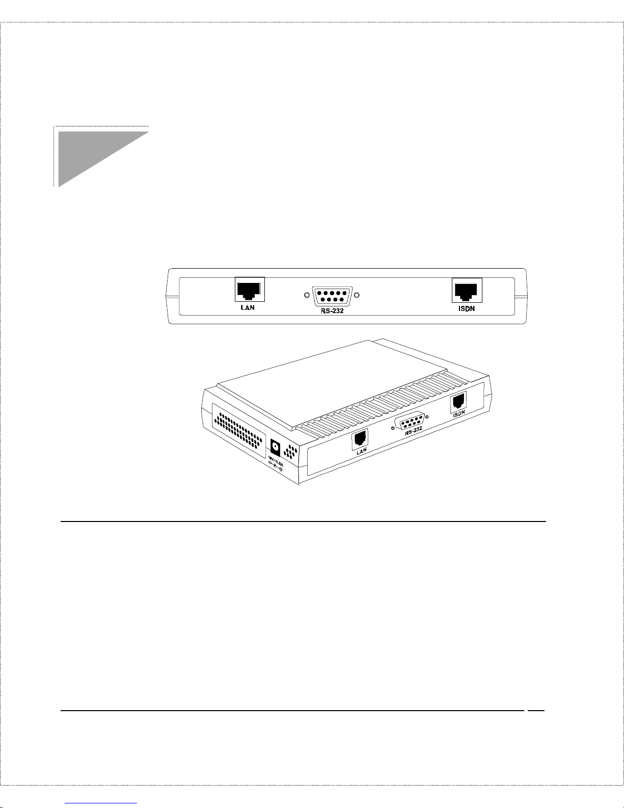
Installation
This chapter outlines how to connect your DI-300 or DI - 300M t o
your LAN and ISDN line. Refer to t he diagram below to identify all
of the ports on your device when yo u make connections.
A Warning On Connection Cables
The RS-232, ISDN line, and Ethernet cable, are very similar to
each other. I t is important that you use the correct cable for each
connection; otherwise, yo ur r outer could be damaged.
Page 30

22 Installation
Connecting Your Computer and Your DI-300 or DI-300M
For the init ial setup o f your DI-300 or DI - 300M, you must use
RS-232 and commu nications software.
After the rout er has been successfully installed, you can mo dify the
configur ation through a remote Telnet connection. See the
Telnet
Configuration and Capabilities
ch ap ter for d eta iled instructions on
using T elnet to configure yo ur DI - 300 or DI-300M.
Connecting the RS-232 Cable to the Router
An RS-232 cable is included in your package. To connect t his
cable, connect t he 9-pin end of the cable to the DCE po r t on the
router’s back panel. Co nnect the other end to the RS-232 cable
connected to the serial port (COM1, COM2, or any other COM
port ) of yo ur computer.
Connecting an ISDN Line to the Router
Plug one end of your I S DN phone line into the socket on the rear
panel of the rout er labeled ISDN and the other end into the ISDN
wall jack .
♦ S/ T i nt erface—This can only connect to your NT-1
(Network Termination) device.
NOTE:
Do not under any circumstances connect directly to the ISDN
wall jack.
Page 31

Installation 23
♦ U int erface—This allows you to connect directly to your
ISDN wall jack.
NOTE:
The ISDN jack is for ISDN line connection only. Connection of
a phone line may r es ult i n dam age to your D I- 300 or D I- 300M .
Connecting an Ethernet Cable to the Router
Your DI-300 or DI-300M is equipped with an RJ-45 jack for
connection to a 10BASE-T E thernet or 100BASE-TX Fast
Ether net hub or swit ch via a standard s tr aight-t hrough twist ed-pair
cable.
Connecting a Power Adapter to the Router
Plug a 12V DC, 500 mA power adapter into the jack on the
rout er ’s side panel labeled POWER
At this point, you should have connected the RS-232 cable, the
ISDN phone line, t he Ethernet cable, and t he power supply. You
can now power up your DI-300 or DI- 300M.
The DI-300 or DI-300M’s Front Panel
Names and descriptions of your router’s front panel LEDs are
given belo w:
Page 32

24 Installation
POWER—Comes on as soon as you connect the router to t he
power supply.
TEST—Should be blinking if the router is functioning properly.
ISDN: LINK—Indicates that the rout er has an ISDN line
connected to the WAN interface and it has been successfully
initialized.
ISDN: B1 and B2—On if there is an active WAN session on that
channel or if that channel is making o r r eceiving a call.
LAN: 10/100—When you co nnect a netwo r k cable to t he DI-300
or DI- 300M, the router w ill au tomatically d etect the ne twork
speed. The 10/100 LED will ligh t up if the LAN is operating a t 100
Mbps.
LAN: Link/Act—When the LAN connection is ready but idle, the
Link/Ac t LE D w ill shine stea dily. When data are be in g tran smitted
or received, this LED will blink off a n d on.
LAN: FDX/COL—The FDX/C OL LED will sh ine gr ee n wh en th e
LAN connection uses full-duplex signaling. It will flash yellow
when the router and anot her device on the LAN transmit at the
same time. Occasional collision s are normal. If collisions are too
frequent, the LAN must be reconfigured to reduce t r affic loads.
Powering Up Your DI-300 or DI-300M
When you power up your DI- 300 or DI-300M, t he ro uter will
per f orm s ever al internal tests an d d o an ISDN line initializa tion .
Page 33

Installation 25
Afte r IS DN line in itialization, the r outer will ask you to p re ss
ENTER to continue.
When you press ENTER, th e r oute r will display a login s creen and
ask you to enter the password, as shown belo w:
Enter t he default password, 1234, to get into the Main Menu of the
System Management Ter minal (S MT ) . Note that once you are in
the SMT and if there is no activity for more than 5 minutes, the
route r will automa tica lly log you out a nd displa y a blank screen. I f
you see a blank screen, press ENTER to bring up the password
screen.
Navigating Through the System Management Terminal
Interface
The SMT is the interface that you use to configure your DI-300 or
DI-300M. Several operations that you should be familiar with
Page 34

26 Installation
before you attempt to modify the co nfiguration of your router ar e
listed b elow :
♦ M oving Forward to Another Menu. To move forward to a
sub-menu belo w the current one, type in the number of the
sub-menu and press ENTER.
♦ Moving Backward to a Previous Menu. Press the Escape
key to move back to the previous menu.
♦ Moving the Cursor. Within a menu, press ENTER (carriage
retur n) to move to the next field. You can also use the Up
and Down keys to move to the previous and the next field,
respectively.
♦ En teri ng I nform ation . There are two t ypes of fields that
you will need to fill in. T he firs t re quires you to type in th e
appropr iate information. The second gives you choices to
choose from. In the seco nd case, pr ess the space bar to cycle
through t he available choices.
♦ Required Fields. Some of the fields in t he SMT ar e essent ial
in order to configure the DI-300 or DI-300M. T hese fields
will in itially show qu estion marks, indicating th at the
infor mation must be fille d in befor e that men u c an be saved.
♦ N/A Fields. Some of th e fie lds in the SMT will sh ow a N/A.
This symbol r efers to an op tion th at is no t availab le or n ot
applicable.
♦ Saving Your Configuration. You can save your
co nfigu ration by pr essing ENTER at the message ‘Press
ENTER to co nfirm or ESC to cancel’. Saving t he dat a on the
scr een will take you in mo st cases to th e p re vious men u.
Page 35

Installation 27
T h e SMT main men u is shown below:
System Management Terminal Interface Summary
T h is sec tion summarizes all major SMT M enus:
#
Menu Title Description
1 General Setup Set up general information and enable routing or bridging
of specific protocols
2 ISDN Setup Set up ISDN configuration
3 Ethernet Setup Set up Ethernet c o n figuration
4 Internet Access Setup A quick and easy way to setup Internet connection
11 Remote Node Setup Set up Remote Nod e for LAN- to -LAN connection
includi ng Inte r net connecti on. A DI-300 or DI-300M can
have up to four Remote Nodes.
12 Static Routing Setup Set up static routes for different protocols. Up to four static
routes can be set for each protocol.
13 Default Dial-in Setup Set up default dial-in parameters such that your DI-300 o r
DI-300M can be a dial-in server for the Remote Node and
Remote Dial-in User.
14 Dial-in User Setup Set up Remot e Dial-in User. Your DI-300 or DI-300M
can directly support up to eight Remote Dial-in Users.
21 Filter Set Conf iguration Set up filters to b e used in Menu 3 and Menu 11 to provide
security, call control, etc.
22 SN MP Conf iguration S et up SNMP -relate d paramet ers (DI- 300M only)
Page 36

28 Installation
#
Menu Title Description
23 System Security Set up security related parameters
24 System Maintenance Provide system status, diagnostics, firmware upload, etc.
99 Exit To exit from S MT and return to th e blank screen
General Setup
This menu contains ad ministrativ e and system-re late d information .
Enter 1 in the main menu to go to Menu 1—General Setup.
1. System Name—Give the ro uter a descriptive name for
identification purposes, e.g., AB CD. This na me should be no
more than 8 alphanumeric characters. Spaces ar e not allowed,
but “-” and “_” are accepted. This name can be retrieved
remotely via SNMP, used for CHAP aut hentication, and will
be dis pla yed as th e p rompt in c ommand inte rpr eter mode. See
the
Dial-In Configuration
chapter starting on page 59 for
more information on CHAP; see the
System Maintenance
Page 37

Installation 29
chapter starting on page 122 for more information on
command inte rprete r mod e.
2. Location—E nt er the geographic lo cation (up to 31
characters) o f your DI-300 or DI - 300M, e. g. , San Jose.
3. Contact Person’s Name—Enter the name (up to 8
characters) of the person in charge of the router. The
Location and the Contact Perso n fields are optional.
4. Protocols—Turn on or off the individual protocols for your
particular application. Unsupported proto cols will have a N /A
in their fields.
ISDN Setup
Menu 2 is for entering information about your ISDN line. Different
telephone companies deploy different types of switches for IS DN
ser v ice . Depending on th e s witch for your par ticu lar installa tion ,
yo u w ill hav e a diffe re nt nu mber of telep h on e numbers, and if you
are in North America, you may also have SPIDs. Make sur e that
you have correct and complete t elephone numbers and SPIDs. You
need to pass the ISDN setup before your system can make an
out g oing call or answer an incoming call.
Page 38

30 Installation
North American ISDN
1. Switch Type—Verify the switch type information with your
telephone company. Fo r North America, select the type of
switch used by your telephone company. I f your switch type
is not cu rre ntly show n, pr ess the space bar to change to the
next switch; repeat until you see t he co r r ect switch type. The
route r will not be ab le to p lace or to receive calls if the wrong
switch type is specified. I f you are not sure, contact your
telephone company t o confirm the exact switch type.
2. B Channel Usage—If yo u ar e using one B channel of your
router with another device on the S/T bus, then select
Switch/Unused. If not choose Switch/Switch. The fo llowing
table shows the relationship between the B Channel Usage
sett ing and ISDN B channels.
B Channel Usage B1 B2
Switch/Sw itc h Switch Switch
Switch/Lease d Switch Leased
Leased/Switc h Leased Switch
Leased/Un use d Leased N/A
Unused/Leased N/A Leased
Leased/Leased* Leased Leased
Page 39

Installation 31
B Channel Usage B1 B2
Leased128** Leased Leased
Switch/U nuse d Switc h N/A
*Leased/Leased = B1 and B2 channels connect to different remote nodes.
**Leased128 = B1 an d B2 channels connect to the same remote node.
3. SPID Number(s)—SPIDs ar e numbers used by a switch for
identificat ion purposes. Depending on yo ur switch type, you
may have zero, one, or two SPI Ds assigned to your line. For
example, if your switch type is Nort hern Telecom Custom,
you will have to enter two SPID numbe rs.
DSS1 & 1TR6 ISDN
Page 40

32 Installation
1. Switch Type—This field is fixed as DSS1 o r 1T R6.
2. B Channel Usage—This field is fixed as Switch/Switch.
3. ISDN Data & Subaddress—Enter the telephone number
and subaddress assigned t o the ISDN dat a call for the router.
It will be use d a s the outg oing CGPN(Calling Pa rty Numb er)
sett ing for ISDN data calls. Note that the rout er only accepts
digit s; do no t include—and spaces in this field. This field
should be no longer than 19 digits for the number and 5 digit s
for the Subaddress. T he Subaddress is only available for
DSS1.
4. Dial Prefix to Access Outside Li n e—Enter the prefix
number if the router is connected to an ISDN PBX. This
nu mber w ill be ad de d to all outg oin g c alls and sh ould be n o
longer than 3 digits. Ot herwise, leave this field blank.
5. PBX Number (with S/T B us Number)—Ent er the S/T bus
number if the router is connected to an ISDN PBX. If this
field is left as bla nk th en the loopback test will be sk ipp ed .
Page 41

Installation 33
When you are finished, press ENTER at the message ‘Pre ss
ENTER to Confirm...’ to save your selections, or press ESC to
cancel. Wh en you press ENT ER, the rou ter will use the in formatio n
that you entered to initialize the ISDN link to the telephone
company switch. It should be noted that whenever the switch type
is cha nged , the ISDN init ializ ation will take slig ht ly longer . In
addition, if you are using the U-interface, the system will also tak e
slightly longe r to initialize.
At this poin t, you will b e a sked if you w ish to che ck if your ISDN
line has been successfully connected to your r outer. I f you select
Yes, the ro ute r will per f orm a loop-ba ck test to che ck the ISDN
line. I f the loop-back test fails, note the error message that you
receive and take the appro pr iate t r oubleshoot ing action.
Ethernet Setup
Menu 3 is used to ente r Ethe rnet r ela ted information. Dep ending o n
the protocols ( TC P/I P or I PX) on your L A N, you will need to
configur e each proto col separately.
Page 42

34 Installation
General Ethernet Setup
This menu deter mines the type of Ethernet interface you are using
as well as the filter sets you w ish to implement to monitor your
Ethernet traffic. From Menu 3—Ethernet S etup, enter 1 to go to
menu 3.1 -General Ethernet Setup.
Input and Output Filter Sets—Filter sets are used to block
certain packets to r educe traffic and to prevent a security br each.
Filt er ing is a very involved subject , so leave these fields blank for
the time being. After you have studied the
Filter Configuration
chapter star ting on page 96, co me back and define the filter sets.
TCP/IP Ethernet Setup and DHCP
If you are setting up your network for the first time, read the
Configuring for Internet A ccess
chapter before proceeding. The
chapter cont ains impo r tant information on how to assign IP
addresses for your networ k.
Page 43

Installation 35
From Menu 3—Ethernet Setup, enter 2 to go to Menu 3.2—
TCP/IP Ethernet Setup.
1. DHCP—This field d etermines whethe r the r outer will act as
a DHCP (Dynamic Host Configuration Protocol) server. If
this control is set to None , DHCP will not b e u sed. I f it is set
to Ser ver, the router w ill ac t as a D HCP s erve r, cap able of
automatically assigning IP add r esses to Windows 95,
Windo ws NT, and other systems that suppor t the DHCP
client. When DHCP is used, the following four items need to
be set.
Do not set t his field to S er ver if there is already a DHCP server
on your network.
2. Client IP Pool Starting Address—DHCP can assign IP
addresses to hosts dynamically instead of requiring t hat each
system have a fixed IP address. IP addresses are allocated
from a block of addresses, usually assigned by your Int er net
provider. The Client IP Pool Starting Address gives the first
address in the reserved blo ck.
Page 44

36 Installation
3. Size of Client IP Pool—Gives the size of the blo ck of
addresses reserved for DHCP addr ess assignment. The
default is 6 addresses; the maximum is 32.
4. Primary DNS Server/Secondary DNS Server—These two
fields are used by DHCP clients (such as Windows 95 and
Wind ows NT systems) for Domain Name Servers. Usua lly
your Inte rnet p rovide r will provide one or mor e name service
host s.
5. IP A d d ress—E nt er the IP address of the DI-300 or
DI-300M in dot ted decimal notation (four 8-bit numbers,
between 0 and 255, separated by periods), e. g. , 192. 68. 135. 5.
Not e that every machine on the TCP/IP net work must have a
unique IP address.
6. IP Subnet Mask—An IP address consists of two parts, the
networ k I D and t he host ID. The IP S ubnet Mask is used to
specify the networ k I D portion of the address, expressed in
dotted decimal notation. Your DI - 300 or DI-300M will
auto matically calculate this mask based on t he IP addr ess that
you assign. Unle ss you have special need for subnetting, use
the default subnet mask calculated by the router.
7. RIP Direction—Th is parameter deter min es h ow the DI-300
or DI-300M handles RIP (Routing I nformation Prot ocol). If
set to Both (d efa ult), th e router will broadc as t its routing
table on the LAN, and incor p orate RI P broadcasts by other
routers into its routing table. If set to In Only, the router will
not broadcast its routing table on the LAN, if set to Out
Onl y, th e ro ute r will broadcast its r outing table b ut ig nore a n y
RIP broadcast packets that it receives. If set to None, the
route r will not p ar ticip ate in an y RI P e xch ange with oth er
routers.
Page 45

Installation 37
Usually, you should lea v e this parameter a t its defa ult of B oth
and let RIP pr opagate the routing information auto matically.
8. RIP Version—Determines what versions of the RIP Rout ing
Information Protocol the router accepts. Cho ices are:
◊ RIP-1 The router w ill accept and send RIP version 1
messages only.
◊ RIP-2B The r outer will accept RIP- 1 and RIP- 2
messages (both broadcast and multicast), and sends RIP-2
messages in broadcast format.
◊ RIP-2M The r oute r w ill accept RIP-1 and RIP- 2
messages (both broadcast and multicast), and sends RIP-2
messages in multic ast format.
Unless there are routers in your environment that do not
understand RIP-2 packets, you should probably set this field to
RIP-2B.
When you are finished, press ENTER at the message ‘Pre ss
ENTER to Confirm...’ to save your selections, or press ESC at any
time to cancel them.
Novell IPX Ethernet Setup
Refer to t he chapter on Novell IPX configuration.
Bridge Ethernet Setup
Refer to t he chapter on Bridging configuration.
Page 46

38 Configuring for Internet Access
Configuring for Internet Access
Menu 4 of the SMT allows you to configure I nt er net access on one
screen. Before you configure yo ur DI - 300 or DI-300M for Internet
access, you need to collect the following info r mation from your I SP
(Internet Service Provider).
♦ IP address of the ISP’s gateway (optional) .
♦ Telephone number(s) of your ISP.
♦ Login name.
♦ Passwo r d for I S P authentication
For yo ur Workstation:
♦ Domain Name Server (DNS)
Page 47

Configuring for Internet Access 39
IP Addresses and the Internet
Conventionally, the Internet ( with a capital I) refers the large-scale
interconnected networks acr oss the wor ld that was originally
developed by the US Department of Defense. The Internet uses
exclusively the TCP/IP suite o f protoco ls. The t er m “internet”
(lower case i), however, refers to any interconnected networks
using any protocol. An inter net can be as simple as two hosts on a
LAN, or it can be as complex as the Internet itself.
Every machine on the Internet must have a unique address within
that internet. If your networ ks ar e isolated from the Internet, e. g. ,
only bet ween your t wo branch offices, you can assign any IP
addresses to the hosts without problems. However, the Internet
Assigned Numbers Authority (IANA) has reserved the following
three blocks of IP addresses specifically for private netwo r ks:
10.0.0.0 — 10.255.255.255
172.16.0.0 — 172.31.255.255
192.168.0.0 — 192.168.255.255
For this reason, it is recommended that you choo se your network
number fro m the above list.
You can o btain your IP address from the IANA, from an ISP, or
assigned from a private netwo r k. If you belong to a small
organization and yo ur I nt ernet access is through an ISP, the ISP
can provide yo u with the Inter net addr esses for your local
networks. On t he o ther hand, if you are part of a much larger
organization, you should consult your network administrator for
the approp r iate IP addr esses.
Page 48

40 Configuring for Internet Access
NOTE:
Regardless of your particular situation, do not create an
arbitrary IP address; always follow the guidelines above. For
more information on address assignment, refer to RFC 1597,
Address Allocation for Private Internets
and RFC 1466,
Guidelines for Management of IP Address Space
.
Once you have determined the IP address range for your local
network, you may want to use DHCP ( Dynamic Host
Configuration Protoco l) to assign addresses to individual hosts o n
the network, as an alternative to manually configuring each host’s
IP settings. See the TCP/IP E thernet Setup and DHCP section on
page 34 for more information about DHCP.
Internet Access Configuration
The following steps describe the set-up pro cedur e to co nfigure
your DI-300 or DI - 300M for Int ernet access. T he information yo u
will n ee d to p rovide will be indicated in bold type.
Page 49

Configuring for Internet Access 41
1. From the Main Menu, enter 4 to go to Menu 4 - Internet
Access Setup, as seen above.
2. ISP’s Name— Enter the name of your Internet Service
Provider, e.g. , myis p. T his informa tion is for identification
purposes only.
3. ISP IP Add r—Enter the IP Address of the remote gateway
at the ISP’s site. If you do not have this data, just leave it
blank.
4. Pri(mary) Phone # and Sec(ondary) Phone Number—
Bot h t he Primary and the Secondary Phone number refer to
the number that your DI-300 or DI - 300M will dia l to connect
to the ISP . The r oute r w ill always call your IS P usin g the
Primary Phon e number first . If the P rimary Phon e number is
bu sy or doe s not a nswer, the router will call the Sec on da ry
Phone number if available. Once connected, the router will
use the BACP (Bandwidth Allocat ion Co nt r ol Protocol) to
establish the second B-channel if PPP/MP is enabled, and the
ISP also supports MP and BACP.
Page 50

42 Configuring for Internet Access
5. My Login Name—Enter the lo gin name given to you by
your ISP.
6. My Pa ssw o rd— E nt er the password asso ciated with the login
na me a bo ve. N ote that this login n ame /p as sword pair is only
for the ro uter to connect t o the ISP’s gat eway. When you use
TCP/IP applications, e.g., FTP, to access t he Int er net from
your wo rkstation, you will need a se pa rate login name and
password for each server.
7. Single User Account—See the following section for a more
detailed discussion on the Single User Account feature. The
default is No.
8. Telco Options: Transfer Rate—This field (which only
applies to outgoing calls) controls the rate at which the data
is transferred between your router and the Internet. T he
opt ions for t his field are:
◊ 64K—The router will place 64Kbps (bits per second)
digit al data calls.
◊ 56K—(For the North Amer ica only) The router will p lac e
56Kbps digital data calls.
◊ Lease—The route r will place leased-line calls.
9. Multilink—Determines whethe r or not Multilink PPP should
be used. Available options are:
◊ Off—The base transfer rate and maximum transfer rate
will b e 6 4Kb ps .
◊ BOD (Bandwidth On Demand)—The base transfer rate
will b e 6 4Kb ps , and the maximum transfer rate w ill b e 1 28
Kbps.
Page 51

Configuring for Internet Access 43
◊ Always— Mu ltilin k w ill alw ays be on ; both the base
transfer rate and maximum tr ansfer rate will be 128 Kbps.
10. Press ENTER at the message ‘Press ENTER to Confirm...’
to conf irm you r selection s, or pres s ESC at any time to
cancel your selections.
11. At th is p oin t, the SMT will as k if you wish to test the
Internet con nection. I f you s elect Y es, the router will c all the
ISP to test the Internet connection. If the test fails, note the
error message that you receive and take the appropriate
troubleshooting steps.
Single User Account
T ypically, if the re are multip le u sers o n the LAN wanting to
concurrent ly access the Internet, they will have to subscribe to
multiple IP addresses o r a Class C subnetwork from the IS P . In
eith er case, these two app roa ches will cost more than a single us er
account.
The Single User Account ( S UA) feature allows custo mers to have
the same bene fits as ha ving a Class C address, but still only pa y for
one IP address, thus saving significantly on subscription fees.
(Check with your ISP before you enable this feature).
This feature may also be used to connect t o TCP/IP r emote nodes
ot her than Internet Service Providers. For example this feature can
be used to simplify the allo cation of IP addresses when connecting
branch offices to the corpo r ate networ k.
The IP address for the Sing le User Account can be either fixed or
dynamically assigned by the ISP (or other remo te node). In
Page 52

44 Configuring for Internet Access
addition, you can also configur e a ser ver, e.g., a Web server, on
your local network and make it accessible by outside users.
If you do not set a server IP addr ess, SUA offers the additional
benefit o f firewall pr otect ion. This is because if no server is defined,
all in coming inquirie s w ill b e filte red out by the r oute r eve n if you
do have a server on your network. This can prevent intruders from
probing your system.
The router accomplishes this address sharing by translating the
internal LAN IP addresses to a single address that is globally
unique on the Internet. For more information on IP address
translation, refer to RFC 1631,
The IP Network Address Translator
(NAT)
.
In summary:
1. SUA is an ideal, cost-effective solution for small offices with
less than 20 host s using a LAN to co ncurr ent ly access the
Internet or ot her remote TCP/IP network.
2. SUA can provide one server address to be accessed by
Remote Dial-in Users, thus controlling the in coming pac ke ts.
3. S UA can provide firewall protection if you do not configure a
ser v er IP address. All incoming inquiries will be filtered out
by the DI-300 or DI - 300M. T herefore, servers on your
network are pr otect ed.
4. UDP and TCP datagrams can be routed. I n addition, ICMP
echo can also be routed.
The figur e below shows an example o f a small office connected to
the Internet via a Single User Account using a DI-300 or DI- 300M.
Not e that if you enable the Single User Account feature, your local
Page 53

Configuring for Internet Access 45
IP address MUST be selected from the list o f IP addresses for
private networks as defined by the IANA.
Configuration for Single User Account
The steps for configuring your DI-300 or DI-300M for Single User
Internet Access are identical to conventional Internet Access, with
the exception that yo u need to fill in thre e e xt ra fields.
Not e that enabling the Single User Account feature will
auto matically create a new entry in the Remote Node Setup menu
(menu 11). Before enabling the Single User Account feature, check
the Remote Node S etup menu to make sure there is space for a
new e ntr y (there must be no more t han three e ntr ies befor e you
enable the Single User Account feature).
Follow st eps 1- 4 from the previous section, Inter net Access
Configuration.
Page 54

46 Configuring for Internet Access
1. Single User Account—Enter Yes to enable the Single User
Account feature. Use t he space bar to to ggle between Yes
and No.
2. Single User Account: IP Addr—If your ISP assigns you a
dynamic IP address, enter 0.0. 0. 0 here. If your ISP assigns
you a static IP address enter that IP addr ess here.
3. Single User Account: Server IP Addr—If you want to
make a single server, e.g. , a Web server, accessible to outside
users, enter that server’s IP addr ess here.
Press ENTER at t he message ‘Press ENTER to Confirm...’ to
con firm your selec tion s or press ESC at any time to cancel your
selections.
At this poin t, the router will a sk if you w ish to te st the Internet
con nection. If you sele ct Yes, th e r oute r will call the ISP to test
the Inter net connection. If the test fails, not e the error message
that you receive and take the appropriate t r oubleshoot ing steps.
Configuring Backup ISP Accounts
Sometimes it may be desir able to con f igu re mo re tha n o ne ISP
account for backup purposes. T he Single User Account feature can
be enabled for all of these accounts, making it co nvenient to switch
Internet S er vice Providers in the event of a failure.
To co nfigure a backup I SP,
1. Configure your primary ISP using Menu 4, as described
ear lier in this ch ap ter.
Page 55

Configuring for Internet Access 47
2. Enter Menu 11, then select the number of an unused r emot e
node.
3. In Menu 11.1, choose a name for your backup ISP account,
set the Active field to No, and enter your outgoing login
name, password, and phone number(s). The Remote IP
Address field should be set to 1. 1. 1. 1.
4. In Menu 11.3, set the remote node’s subnet mask to 0.0.0. 0,
and set RIP to None.
5. S a ve the new configurat ion.
Once you have done this, if you need to change from yo ur pr imary
ISP to a backup ISP follow the steps below:
1. Enter Menu 11 and select your Primary ISP.
2. In Menu 11.1, set the Active field to No.
3. Enter Menu 11 again and select your backup ISP.
4. In Menu 11.1, set the Active field to Yes.
You will now b e a b le to access the Internet through the backup ISP
Remote Node.
Page 56

48 Remote Node Configuration
Remote Node Configuration
A Remote Node represents both a remote gateway and the internet
behind it, across an ISDN connection. A Remote Node is required
for placing calls to or answering calls from a remote netwo r k. Note
that when you use Menu 4 to configure the Internet, your DI-300
or DI-300M will au tomatically add a Remote Node for you. Once a
Remote Node is configur ed pr operly, traffic to t he remote LAN
will trig ge r the router to mak e a ca ll au tomatically ( i.e. , Dial On
Demand). S imilar ly, calls fr om th e remote LAN w ill be ans we red
automatically and security will b e c hecked .
In this chapter , we will d iscus s the pa rameter s that are pro tocol
ind epen de n t. The protoc ol de pe ndent c onfiguration will be cov ered
in subsequent chapters. For TCP/IP, see the
TCP/IP Configuration
chapter on page 70. For I P X, see the
Novell IPX Configuration
chapter on page 79. For bridging, see the
Bridging Configuration
chapter on page 89.
From the Main Menu , enter 11 to go to Menu 11—Remote Node
Setup. When in menu 11, enter the number of the Remote No des ( 1
to 4) that you wish to configur e as sho wn below:
Page 57

Remote Node Configuration 49
E n ter the Remote Node numb er to edit an d you will go to the nex t
submenu: 11.1 - Remote No de Pr ofile, as shown below:
1. Rem Node Name—This is a required field. Enter a
descriptive name for the Remo te Node, e.g., SJHQ. The
name can be up to eight characters long, and must be
Page 58

50 Remote Node Configuration
different from any other Remote Node name or Remo te Dialin U ser n ame.
2. Act ive—Press the space bar to t oggle between Yes and No.
When a Remote Node is deactivated, it has no effect o n t he
oper ation of the router , eve n thou gh it is still kept in the
database, and can be activated in the future. Deact ivated
nodes are displayed with a minus sign [-] at the beginning of
the name in M enu 11.
3. Call Direction—If this parameter is set to Both, your DI-300
or DI- 300M can both place and receive calls to/from this
Remote Node. If set to Incoming, the rou ter will n ot place a
call to this Remote Node. If set to Outgoing, the router will
drop any call from this Remote Node .
Sever al other field s in this me nu depe nd on this parameter. F or
example, in order to enable Call Back, the Call Direction mu st
be Bot h.
4. Incoming: Rem Node Login Name—Ent er the login name
tha t th is Remote Nod e w ill us e when it ca lls into the r oute r.
T h e log in na me in th is field c omb ined with the Rem Nod e
Password will be used to authentic ate th e incoming ca lls fr om
this node.
5. Incomin g : Rem Node Pa sswo rd —E nter the password used
wh en th is Remote Nod e calls in to th e router .
6. Incoming : Rem CLID—This field is active only if Call
Direction is either Both or Incoming. Otherwise, an N/A
app ears in the field. This is the Calling Line ID ( th e te lep h one
numbe r of the c alling p arty) of th is Remote Nod e. If you
enable the CLID Authen field in Menu 13—Default Dial In,
the router w ill check this nu mber a ga inst the CLI D in th e
Page 59

Remote Node Configuration 51
incoming call. If they do not match and the CLID Authen is
Required, the n the rou ter will re ject the call.
7. In coming : Call Back—T h is field w ill be v alid only if Call
Direction is Both. Ot herwise, an N/A appears in the field.
This field determines whether or not you wish the router to
call back after receiving a call from this Remote No de. If this
option is enab led , the ro ute r will discon nect the initial call
from this node and call it back at the Outgoing Primary
Phone Number (see below).
8. Outgoing: My Login Name—This is a required field if Call
Direction is either Both or Out. Enter the login name for the
route r whe n it ca lls this Re mote Node . If the login name is
long er tha n 24 chara cters, only the firs t 23 will be disp laye d,
with a + displayed at the end.
9. Outgoing: My Password—This is a requir ed field if Call
Direction is either Both or Out. Enter the password for the
route r whe n it ca lls this Re mote Node . If the password is
long er tha n 20 chara cters t hen a + will be disp layed a t the
end.
10. Outgoing: Authen—This field set s the authentication
protocol used for outgoing calls.
Your DI-300 or DI-300M supports two authentication
protocols: PAP (Password Authentication Protocol) and CHAP
(Challenge Handshake Authentication Pro tocol).
◊ PAP sends the user name and password in plain text.
◊ CHAP scrambles the password before it is sent over the
wire.
Gene rally speak ing, C HAP is more se cu re than PAP; h owe ver,
PA P is re ad ily availab le on more platforms. The
Page 60

52 Remote Node Configuration
recommendation is to use CHAP whenever possible. Turning off
the authentication is STRONGLY discouraged.
Options for this field ar e:
◊ CHAP/PAP—The ro uter will try CHAP when CH AP is
requested by the Remote Node o r PAP when PAP is
requested by the Remo te Node.
◊ CHAP—use CHAP only.
◊ PAP—use PAP only.
11. Outgoing: Pri(mary) Phone Sec(ondary) Phone
Number—Both the Primary P ho ne number and the
Secondary Phone number refer to the number that the router
will dia l to connect to th e Remote Nod e. T he rou ter will
always call the Remote Node u sing the Prima ry Phone
number fir st. If the Primary Phone number is busy o r does not
an swer, th e router will c all the Sec on da ry Phone number if
av aila ble. O nce con nected, the rout er will use the BA CP
(Ba ndwidth Allocation Contro l Protocol) to establish the
secon d B -c han nel if Multilin k PPP is enabled, and the Remote
Node supports MP and BACP.
Some areas require dialing # before the phone number for local
calls. A # symbol may be included at the beginning of the
Primary Phone number o r S econdary Phone number.
12. Rout e—This fields det er mines the prot ocols that your
DI-300 or DI - 300M will route. The choic es for this field are
determined by the features enabled on your r outer.
13. Bridge—Bridging is used (on the DI-300M only) for
prot ocols that are not supported o r not turned on in the
previous Route field, e.g., SNA. When bridging is enabled,
the DI-300M will forwar d a n y pa ck et that it does not
Page 61

Remote Node Configuration 53
recognize to t his Remot e Node; otherwise, the unrecognized
packets are discarded. The disadvantage o f bridging is that it
usually generates large amounts o f tr affic. Press the space bar
to select either Yes o r No.
14. Ed i t PPP Optio n s—To edit the PPP options for this Remote
Node, move the cursor to t his field, use the space bar to
select Yes and press ENTER. This will b ring you t o Menu
11.2—Remote Node PPP Opt ions For mo re information on
configuring PPP options, see the section Editing PPP
Options.
15. IP Addr—This is a required field if Ro ute is set t o IP. Enter
the IP address of this Remote Node.
16. Edit IP/IPX/Bridge Options—To edit the parameters of the
prot ocols, go to this field, select Yes and press ENTER. This
will b rin g you to Menu 11 .3— Remote N ode Ne twork Layer
Options . For more in forma tion on filling out this screen, re fer
to the chapter pertaining to your specific proto col.
17. Telco Options: Transfer Rate—This field ( which only
applies to outgoing calls) controls the rate at which the data
is transferred between your router and the Remote Node. T he
opt ions for t his field are:
◊ 64K—The router will place 64Kbps (bits per second)
digit al data calls.
◊ 56K—(For North A merica only) T h e router will p lac e
56Kbps digital data calls.
◊ Lease—The r oute r will place leased-line calls.
18. Telco Options: Allocated Budget (min)—T h is field w ill set
a budget out going call time for t he Remote No de. T he default
for this field is 0 for no budget co nt r ol.
Page 62

54 Remote Node Configuration
19. Telco Options: Period (hr)—This field w ill set the time
interval to reset the above outg oing call budget control.
20. Session Option: Input Filter Sets, Output Filter Sets and
Call Filter S ets—In t hese fields, select which filter set( s) you
would like to implement to filter the in coming an d ou tgoing
traffic bet ween t his Remot e Node and the rout er . You can
choose from 12 differ ent filter sets. In addition, you can link
up to 4 filter sets together for furt her cust omization (e.g., 1,
5, 9, 12). Note t hat spaces and commas are accepted in this
field.
F or more in forma tion on customizing your filter sets, see the
Filter Configuration
chapter starting on page 96. The default is
blank, i. e ., no filters defined .
21. Session Option: Idle Timeout (sec)—This value specifies
the number of idle seconds t hat elapses before the Remote
Node is automatically disconnected. I d le seconds is the
period of time wher e no data is passed between the Remote
Node and your DI-300 or DI - 300M. Administrat ive packets
such as RIP are not counted as data. T he default is 300
seconds (5 minutes).
On ce you have comp lete d filling in M enu 1 1.1—R emote Nod e
Profile, press ENTER at the message ‘Press ENTER to Confirm...’
to confirm your selections, or press ESC at any time to cancel your
selections.
Bandwidth on Demand
The Bandw idth on Demand (BOD) feature allows you to bundle
both B channels in one connection. The second channel is added
Page 63

Remote Node Configuration 55
and subtracted dynamically according to traffic demand. The router
uses the Bandwidth Allocation Cont r ol Protocol (BACP) and the
Multilink Protoc ol (M P) to implement ban dwidth on de mand.
The configu ration of bandwidth on demand focu s e s on the Ba s e
Transmission Rate (BTR) and the Maximum Transmission Rat e
(MTR). T he relationship between BTR and MTR are shown below:
BTR & MTR Setting No. of channel(s)
used to initiate call
Max No. of
channel(s) used
Bandwidth on
demand
BTR = 64, MTR = 64 1 1 Off
BTR = 64, MTR = 128 1 2 On
BTR = 128, MTR = 128 2 2 Off
When bandwidth on de mand is enable d, a second ch ann el w ill be
bro ught u p if tr affic on th e initial ch annel is high er th an th e high
Target Utility n umber for longer than the specifie d Add Pe rs ist
va lue . Similarly, the second channel will be dr opp ed if th e tr affic
lev el falls belo w the low Ta rget Utility nu mb er fo r longe r than the
Subtract Persist value.
T h e Target Utility specifies the line utiliz ation range at which you
want your DI-300 or DI -300M to add or subtract bandwidt h. The
range is 30 to 64 kbps (kilobits per second). The parameters are
separated by a -. For example, 30-60 means the add threshold is 60
kb ps and subtra ct threshold is 30 kbps. The r outer will perform
ba ndwid th on demand on ly if it init iate s the call. Addition a nd
subtract ion are based on the value set in the BOD Calculation field.
If this field is set to T r ansmit or Receive, then traffic in either
dire ction will be calculated to de ter mine if a link sh ould be adde d or
drop pe d. T rans mit will only use outgoing traffic to mak e this
determination, and Receive will on ly us e incoming traffic to make
this de termina tion .
Page 64

56 Remote Node Configuration
If, after making the call to bring up a second channel, t he second
channel does not succeed in joining the Multilink Protocol bundle
(because the remote device does not r ecognize the second call as
coming from the same d evice), the rou ter will h ang up the second
channel and continue with the first channel alone.
Editing PPP Option s
1. Encapsulation—Select CCP ( Compression Control
Proto col) for the PPP or MP link. There are two options in
this field.
◊ Standard PPP—St andard PPP options will be used.
◊ CISCO PPP— Cisco PPP options will be used .
2. C ompressi on— Turn o n t he Stac Compression. The default
fo r this field is Off.
Page 65

Remote Node Configuration 57
3. M ultiple Li nk Options: BOD Calcu lation—Select the
direction of the traffic yo u wish to calculate in order t o
determine when to add or subtr act a link. T he default for this
field is Transmit or Receive.
4. Multi p le Link Option s: Base Trans Rate—Select the base
data transfer rate for this Remote Node. This parameter is in
kilobits per second (Kbps). There are t w o options for this
field:
◊ 64—Only one chann el w ill be used .
◊ 128—Two ch ann els will be used w hen a p ac ke t trigger s a
call.
5. Multiple Link Options: Max Trans Rate—Enter the
max imum d ata transfer rate allowed for this Remote Node.
T his para mete r is in kilob its per secon d. T here are two
options for this field:
◊ 64—At most one channel can be used.
◊ 128—A ma x imum of two channels ca n be used .
6. M u ltiple Link Options: Target Utility—E nt er the two
thresholds separated by a—for subtracting and adding the
second channel. The default is 32-48.
7. Multiple Link Options: Add Persist—This parameter
specifies the number of seconds where traffic is above the
adding th reshold befo re the router w ill b ring u p the secon d
channel. The default is 5 seconds.
8. Multiple Link Options: Subtract Persist—This paramet er
specifies the number of seconds where traffic is below the
subtract ion threshold before the router dro ps the second
channel. The default is 5 seconds.
Page 66

58 Remote Node Configuration
Once you have completed Menu 11.2—Remote Node PPP
Options, press ENTER at the message ‘Press ENT E R to
Confirm...’ to confirm your selections, or press ESC to cancel your
selections.
Page 67

Dial-In Configuration 59
Dial-In Configuration
You can configur e your DI- 300 or DI-300M t o receive calls from
Remote Dial-in Users (e.g., t elecommuters) and Remote Nodes.
There are several differ ences between Remote Dial-in Users and
Remote No de s:
1. The rout er can make calls t o or answer calls from a Remote
Node. Ho we ver, it will only ans wer calls from Remote Dialin U se rs .
2. Each Remot e Node can have its own set of parameters such
as Bandwidt h On Demand, Protocol, Security, etc., while all
Remote Dial-in Users share o ne co mmon set, as defined in
the Default Dial In Set up ( Menu 13).
3. Generally, Remote Dial-in Users are individual users who dial
in to the DI-300 or DI - 300M directly from their
workstations, while Remot e Nodes represent networks and
are used for LAN-to - LAN connections.
This chapter discusses how to set up Default Dial-in parameters for
both Remote Node and Remot e Dial-in Users. The following
sections give t wo examples of how a DI-300 or DI - 300M can be
configur ed as a dial-in server for either or both.
By default, your DI-300 o r DI - 300M allows information for up to
eight users to be kept. To let more than eight remot e dial-in users
access a DI-300M, you can use a separate RADIUS server to
provide remote authentication services. Fo r details o n using a
separate RADIUS ser ver, see the
Using RADIUS Authentication
section on page 118.
Page 68

60 Dial-In Configuration
Telecommuting
Telecommuting enab les pe ople to wor k a t re mote sites and still
have access to t he resources in the business o ffice. Typically, a
telecommuter will use a c lient works tation w ith T CP /IP or IP X
an d dial-ou t capa bilities, e.g., a W indows 95 PC or a Ma cintos h
and an ISDN Terminal Adapter (TA). For telecommut er s to call
in to your LAN, you need to configure a Dial-In User Profile for
each telecommut er. Additionally, you need to co nfigure the
Default Dial-In Setup to set the operational parameters for all
dial-in users. You can configure up to eight Remote Dial- in
Users for your DI- 300 or DI-300M.
An example o f Remote Dial-in User application, telecommuting,
is shown below:
Dial-In Server Application
A DI-300 or DI - 300M can also be used as a dial-in server. This
application allows the router to provide services for
workstations on a remote network. For the router to be set up as
Page 69

Dial-In Configuration 61
a dial-in server, you need to co nfigure the Default Dial-In Setup
to set the operatio nal parameter s for in coming call. Ad ditionally,
yo u w ill hav e to cre ate a Remote Nod e for th e r outer on th e
remote network (see the
Remote Node Configuration
chapter
start ing on page 48). An example of a DI-300 or DI- 300M being
used as a dial-in server is shown below:
Default Dial-In Setup
This section covers the default dial-in parameters. The
par ame ter s in M enu 13 a ffect incoming c alls from a ll Remote
Dial-in Users and Remote Nodes before aut hentication is
completed . Onc e a uthentic ation is completed, and if it matche s a
Remot e N ode, the ro ute r w ill us e parameters from that
particular Remo te Node.
Page 70

62 Dial-In Configuration
From the Main Menu, enter 13 t o go t o Menu 13 - Default Dial-in
Setu p. T his s ec tion will d es cr ibe h ow to configure th e p rotoc olindependent fields in this menu. For the pro tocol-dependent fields,
refer to the appropriate chapters.
1. Telco Options: CLID Authen.—This field sets the CLID
authentication parameter for all incoming calls. There are
three options for this field:
◊ None—No CLID is required.
◊ Required—Must provide CLID, or call is disconnected.
◊ Preferred—If the CLI D is availab le then CLI D w ill be
used to do authentication. If the CLID is not available the
call will continue .
2. PPP O ption s: Recv. A uthen .—This field sets the
authentication protocol used for incoming calls. User names
and passwords are co nfigured in t he next sect ion (Remote
users/Dial-in Users Setup). Options for this field are:
Page 71

Dial-In Configuration 63
◊ CHAP/PAP—T he rou ter will try CHAP first, but P A P
will b e u sed if C HAP is not available.
◊ CHAP—Use CHAP only.
◊ None—No authentication required.
3. PPP Opti o ns: Comp ressio n —The setting in this field
determines if Sta c compr ession will be used . The default
setting is Yes.
4. PPP Op tions: Mutu a l Au then. —Some vendors, e.g. Cisco,
implement a t ype of mutual authentication. That is, the node
tha t init iate s the call will re quest a user name and password
from the far end that t hey are dialing to. I f the Remote No de
tha t is dialing in implements t his type of au th entication , set
this field to Yes.
5. PAP Log i n—T his field will only be enab led if the Mutual
Authen. field is set to Yes. Enter in the login name to be used
to r espond to the far end’s PAP authentication request. This
field does not apply t o CHAP authentication.
6. PAP Password—T his field will only be enab led if the Mutual
Authen. field is set to Yes. Enter in the PAP password to be
used to r espond to the far end’s authentication request. This
field does not apply t o CHAP authentication.
7. Multiple Link Options: Max Trans Rat e—Enter the
maximum data t r ansfer rate between your ro uter and the
Remote Dial-in User. The unit is in bits per second. There
are two options for this field:
◊ 64—At most, one B channel will be used .
◊ 128—A ma ximum of two chan nels can be u sed.
Page 72

64 Dial-In Configuration
When the DI-300 or DI - 300M calls back to t he Remote
Dial-in User the maximum data transfer rate is always 64.
8. Callback Budget Management: Allocated Budget (min)—
This field will set a b udget callback t ime for all the Remote
Dial-in Users. The default for this field is 0 for no budget
control.
9. Callback Budget Management: Period (hr)—This field
will set th e time in terva l to re set the above callback budget
contro l.
10. Dial-In IP Address Supplied By: Dial-in User—If set to
Yes, it tells the DI-300 or DI- 300M to allow a remote host to
specify its own IP addr ess. T his is to prevent the remote host
from using an invalid IP address and potentially disrupting the
whole network. If set to No, the remote host must use the IP
address assigned by t he DI-300 or DI-300M from the IP
pool, configured below. The default is Yes.
11. Dial-In IP Address Supplied By: IP Pool—Th is field tells
your DI-300 or DI- 300M t o provide the remot e host with an
IP address from the pool. This field is required if Dial-In IP
Address Supplied By: Dial-in User is set to No. You can
configure this field even if Dial-in User is set to Yes, in which
case the DI-300 or DI -300M will accept the IP address if the
remote peer specifies one; otherwise, an IP address is
assigned from the pool. If Dial-in User is Yes and this field is
No, the remote peer
must
supply its own IP address, or
communic ation will not be pos sible. Th e defa ult is No.
12. IP Pool: IP Start Addr—This field is ac tiv e only if you
selected Yes in the Dial-I n IP Address Supplied By: I P P ool
field. The IP po ol contains contiguous IP addresses and t his
field specifies the first one in the pool.
Page 73

Dial-In Configuration 65
13. IP Count (1,2)—In this field, enter the number (1 or 2) of
the addresses in the IP Poo l. For example, if the star ting
address is 192.168.135.5 and the count is 2, then the pool
will h ave 192.68.135.5 and 192.68.135. 6
14. Dial-In IPX Net. Num. Supplied By: IPX Pool—This field
tells the DI-300M to provide the remot e host with an IPX
network number from the pool. Otherwise, the router will
generate a random IPX network number. The default is No.
15. IPX Start Net. Nu m.—This fie ld is ac tiv e only if you
selected Yes in the Dial-In IPX Net. Num. Supplied By: IP X
Poo l field. The IPX pool contains contiguous IP X network
number s and t his field specifies the first o ne in the pool.
16. IPX Count (1, 16) —I n t his field, ent er the number (1—16)
of network numbers in t he IPX P ool. For example, if the
start ing number is 12345678, and the count is 2, then the
pool will have 12345678 and 12345679.
17. Session Options: Input Filter Sets and Session Options:
Output Filter Sets—In these fields, you need to select the
filter set(s) t o filter the incoming and outg oing traffic between
your DI-300 or DI - 300M and the Remote Dial-in User. Keep
in mind that the se filter set(s) will only apply to all Re mote
Dial-in Users but not the Remote Nodes.
You can choose from 12 differ ent filter sets. In addition, you can
link up to 4 filter sets toget her for further customizat ion (e.g., 1,
5, 9, 12). Note t hat spaces and co mmas are accepted in this
field. For more info rmatio n o n customizing your filter sets, s ee
the
Filter Configuration
chapter on page 96. The default is
blank, i.e., no filters.
18. Session Op t i o ns: Idle Timeou t—This value is the nu mber
of idle seconds that elapses before the dial-in user is
Page 74

66 Dial-In Configuration
automatically dis connec ted . Id le T imeou t is the per iod of
time when t here is no data tr affic between the dial-in user or
Remote Node a n d the r oute r. This field will only b e u sed if
Recv. Authen is set to None and the call is not mapped to any
Remote Node or Remote Dial-in User, or the router calls
back to the Remot e Dial-in User.
On ce you have comp lete d filling in M enu 13—Default Dial-in
Setup, press ENTER at the message ‘Press ENTER to Confirm...’
to save your selections, or press ESC at any time to cancel your
selections.
Dial-In Users Setup
The following steps describe the setup pro cedure for adding a
Remote Dial-in User. From the Main Menu, enter 14 to go to 14.
Dial-in Use r Se tup is shown below :
Page 75

Dial-In Configuration 67
Sele ct one o f eig ht us ers by numb er, th is w ill b rin g you to th e next
screen, Menu 14.1 - Edit Dial-in User.
1. User Name—This is a required field . This will b e u se d a s the
login name for authentication. Choo se a descriptive word for
login, e.g., kathyg.
2. Active—You can disallo w dial-in access to this user by
sett ing this field to Inactive. When set to inactive, the user
rec ord is still kept in th e data b ase for later activ ation.
Deactivated users are displayed with a—(minus sign) at the
beginning of the name in Menu 14.
3. Password—Enter the password for the Remote Dial-in User.
4. Callback—This field determines if the DI-300 or DI- 300M
will allow ca llb ac k to the Remote Dial-in User upon dial-in. If
this control is set to Optional, the r outer will be able to call
back to the Remot e Dial-in User if so requested by that user’s
system; if the control is set to Mandatory, the router will
att empt callback in all cases. Callback entails disconnecting
Page 76

68 Dial-In Configuration
the call and dialing the specified callback number (see below).
The default setting of this control is No.
5. Phone # Supplied by Caller—This co ntrol allows the
Remote Dial-in User to specify t he callback telephone
number on a call-by-call basis. This is useful for when the DI300 or DI- 300M returns a callback to a mobile user at
different numbers, e.g., a sales rep in a hot el. Note that the
default is No, i.e., the router always calls back to the fixed
callback number.
6. Callback Phone #—I f Ca llback is Yes, th en this is a required
field. Other wise, N/ A will appe ar in the field. Enter th e
telephone n umber t o which the ro ute r will call back.
7. Rem CLID—If you have enabled the CLID Authen field in
Menu 13, you need to specify the telephone number from
which this Remot e Dial-in User calls. The DI-300 o r
DI-300M will check this number again st the CLID in the
incoming call. If they do not match and the CLID Authen is
Required, the rou ter will re jec t th e c all.
8. Id le Ti me- o u t—E nter the idle time (in se conds). This time-
out determines how long the dial-in user can be idle before
the DI-300 or DI - 300M disconnects the call. I d le time is
defined as the period o f time where there is no data tr affic
between the dial-in user and the rout er . T he default is 300
seconds (5 minutes).
More on CLID
CLID allo ws your DI-300 or DI-300M t o authenticate the caller
before a call is answered, thus saving the cost o f a connection. The
Page 77

Dial-In Configuration 69
router uses the caller ID in the ISDN call setup message to match
against t he CLID in the database.
Howeve r, CL ID may not be available due to your switch
configur ation.
Besides authentication, another application of CLID is to
combine
it with callback. For instance, your company pays for the
connection charges for telecommu ting employees, and you are
using the DI-300 or DI- 300M as t he dial-in server. You can tu r n on
both the CLID authentication and callback options for the dial-in
users. By doing so, all usage ar e charged to t he company instead of
the employees, and yo ur accounting department can avoid the
hassles of accountability a nd reimbu rs eme nt.
On ce you have comp lete d filling in M enu 1 4.1—Edit Dial-in User,
press ENTER at the message ‘Press ENTER to Confirm...’ to save
your selections, or press ESC at any time to cancel your selections.
Page 78

70 TCP/IP Configuration
TCP/IP Configuration
This chapter shows you how to configure your DI-300 o r
DI-300M for TCP/IP. Depending on your par ticular
applica tion s, you w ill n ee d to con f igu re diffe rent menus. Fo r
instance, Int e r net access is the most common application of
T CP /IP. F or this app lica tion , you sh ould configure Menu 4. We
will illustra te the configuratio n fo r other ap plications in the
fo llowing section s.
IP Subnet Mask
A subnet mask is a 32-bit quantity that, wh en logically ANDed with
an IP address, yields t he network number. For instance, the subnet
masks for class A, B and C netwo rks without su bnet ting are
255.0.0.0, 255. 255. 0.0 and 255.255.255.0, respectively.
To cr eate more netwo r k numbers, you shift some bits from the host
ID to the network ID. Fo r instance, t o partition a class C network
number 192.68.135.0 into two , you shift 1 bit from the host ID to
the network ID. Thus th e new subne t mask w ill be
255.255.255.128; the first subnet will have networ k number
192.68.135.0 with hosts 192.68.135.1 t o 129.68.135.126 and the
secon d subnet will ha ve n etw ork nu mber 192.68.135.128 with
hosts 192.68.135.129 t o 192.68.135.254.
It is recommended that you use t he same subnet mask fo r all
physical networks that share an IP net work number. The t able
below lists the additional subnet mask bits in dot decimal notations.
To use to following table, write down the o r iginal subnet mask and
Page 79

TCP/IP Configuration 71
substitute the higher order 0s with the dot decimal of the additional
subnet bits . Fo r insta nc e, to p artitio n yo ur clas s C ne twork
204.247.203.0 with subnet mask 255.255.255.0 into 16 subnets (4
bits), t he new subnet mask becomes 255.255.255.240.
Number of Bits Dot Decimal
1 128
2 192
3 224
4 240
5 248
6 252
7 254
8 255
LAN-to-LAN Application
A typical LAN-to-LAN application is t o use the DI-300 or
DI-300M to call from a branch office to t he headquarter s, as
depicted in the following diagram.
For the branch office, you need to configure a Remote Node in
order to dial out to t he headquarter s. Additionally, you may also
need to configure Static Routes if some services reside beyond the
immediate remote LAN.
Page 80

72 TCP/IP Configuration
Remote Node Setup
Follow the pro cedur e in the
Remote Node Configuration
chapter
startin g on page 48 to fill th e protoc ol-indepe n de nt par ameter s
in Menu 11, Remote Node Profile. For the pro tocol-dependent
par ame ters, follow th e instr uc tion s belo w. I f you are con figuring
the router t o receive an incoming call, you also need to set the
default dial-in parameters in menu 13 (see t he
Dial-In
Configuration
chapter starting on page 59).
1. Route—Make sure IP is among the protocols in the Route
field.
2. IP Address—Enter the IP address of the gat eway at t he
remote site (in this case, headquarters). If the remote router is
using a different IP address than the one entered here, your
DI-300 or DI - 300M will dr op the call.
3. Edit IP/IPX/Bridge—Press t he space bar to change it to Yes
and press Enter to go to the Menu 11.3—Remote Node
Network Layer Options menu shown below:
Page 81

TCP/IP Configuration 73
1. Rem IP Address—This will s how th e IP ad dress you e ntere d
for th is Remote Node in the p reviou s men u.
2. Rem IP Subnet Mask—Enter the subnet mask for the
remote network.
3. My WAN Ad dr—Some imp leme n tations, espe cia lly the
UNIX de rivat ives , re quire hosts on both ends o f the I SDN
link to have separate addresses from the LAN, and that the
add re sses mus t h ave the same n etw ork number. If th is is the
case, enter the IP address assigned to the WAN port of your
DI-300 or DI - 300M. Note t hat this is the address assigned to
the local DI-300 or DI-300M, not the remote router.
Page 82

74 TCP/IP Configuration
1. Single User Account—This field should be set to yes to
enable the Single User Account (Network Address
Translator) featur e for this site. Use the space bar to to ggle
between yes and no. See page 43 for more information on the
Single User Account feature.
2. Server IP address—If you are using the Single User
Account feature and you want to make a server accessible on
your LAN, e.g., a web server, accessible to outside users,
enter t hat ser vers I P addr ess here.
3. Metric—The metric represents the “cost” of transmission for
rout ing purpose. IP routing uses hop count as the
measurement of cost, with a minimum of 1 for directly
connected netwo r ks. Enter a number that appro ximates the
cost for this link. The number need not be precise, but it must
be between 1 and 16. In practice, 2 or 3 is usually a good
number.
4. Private—This parameter determines if yo ur DI- 300 or
DI-300M will include th e route to this Re mote Node in its
RIP broadcasts. If set to yes, this route is kept private and
not included in RIP broadcasts. If no, the route to this
Page 83

TCP/IP Configuration 75
Remote Node w ill be pr opa ga ted to other hosts through RI P
broadcasts.
5. RIP—This parameter determines how your DI-300 or
DI-300M handles RIP (Rout ing Information Protocol), and
the defau lt is Both . If set to Both, you r router will broadc ast
its rout ing table on the WAN and incorpo r ate RIP broadcasts
from the other router into its routing table. If set to In Only,
your router will not broadcast its rou ting table o n the W AN;
if set to Out On ly, it will broadcast its r outing tab le but
ignore any RIP broadcast packets that it receives. If set to
None, your DI-300 or DI - 300M will n ot pa rtic ipa te in any
RIP exchange with other routers. Usually, you should leave
this parameter at its default of Both and let RIP propagate the
routing information au tomatically.
On ce you have completed filling in the Ne twork Layer Opt ions
Menu, press ENTER t o return to Menu 11. Press ENTER at the
message ‘Press ENTER to Confirm...’ to save your selections, or
press ESC at any time to cancel your selections.
Static Route Setup
On a directly connected internet, RI P usually handles the rout ing
auto matically. However, RI P cannot propagate across isolated
networ ks, as in the case before a connection is made between the
two subnetwo r ks using one Class C IP address. Without a route, no
packets can be forwarded to their destinations. A static route is
used to reso lve this problem by providing the DI-300 or DI - 300M
with some static routing information. As a matter of fa ct, wh en you
configure the Inter net Access o r a Remot e Node, a st atic route is
implicitly created. An example is given below. In the example,
stations on the 204.5.1. 0/24 subnetwor k can access the remote
Page 84

76 TCP/IP Configuration
statio ns usin g the static route. The route will have a d estination of
204.5.1.64/26 with the gateway address being that o f the Remote
Node (204.5. 1. 150) .
Note that in normal circumstances, your DI- 300 or DI-300M will
have adequate routing information after you co nfigure it for
Internet access and Remote No des; you do not need to configure
add ition al static routes. You will need to con f igu re static rou tes
only for unusual cases, e.g., subnetting. To create additional static
rout es for IP, use Menu 12, Static Route Setup, as shown below:
Page 85

TCP/IP Configuration 77
1. Route Name—Enter a descriptive name for this route. T his
is for identification pu rpose o nly.
2. Act ive—This fields allows you t o activate/deactivate this
stat ic route.
3. Destination IP Address—This parameter specifies the IP
network
add re ss of the fin al d estination. Routin g is alw ays
Page 86

78 TCP/IP Configuration
based on network number. If yo u need t o specify a route to a
single host, use a subnet mask of 255.255.255.255 in the
subnet mask field to force the netwo r k number to be identical
to the host ID.
4. IP Subnet Mask—Enter the subnet mask for this
destin ation. Follow the discussion on IP subnet mask in this
chapter.
5. Gat eway IP Address—Enter the IP address of the gateway.
The gateway is an
immediate
neighbor of the DI-300 or
DI-300M that w ill forw ar d packets to the d estin ation. On the
LAN, the gateway must be a router on the same segment as
the DI-300 or DI - 300M; over IS DN, the gateway must be t he
IP address of one of the Remote Nodes.
6. The Metric and the Private parameters have the same
meaning as those in the Remot e Node Setup.
On ce you have comp lete d filling in the me n u, p re ss ENTER at the
message ‘Press ENTER to Confirm...’ to save your selections, or
press ESC at any time to cancel your selections.
Page 87

Novell IPX Configuration 79
Novell IPX Configuration
This chapter shows you how to configure the DI-300M for IPX.
Dep ending on your pa rticular app lica tion s, you will need to
conf igu re differ ent me nus. W e w ill illustrat e the conf igu rat ion
for some applic ations in t he following sections .
IPX Network Environment
Frame Type
The stat ions on an IPX netw ork (both clients and servers) can run
on four different frame types existing on one physical Ethernet
cable. These frame types are 802.2, 802.3, Et hernet II ( DI X) , and
SNAP.
Network Numbers
Whenever you are setting up an IPX routing environment, it is
important to co r r ectly co nfigure the network numbers on t he LAN.
On any IP X network, t here is an external network number, that is,
the number associated with the frame type on the Ethernet cable to
which the stations on the netwo r k ar e joined. In addition to this
external network number, each NetWare server has its own internal
ne twor k number . It is import ant to remember that eve ry netw ork
number has t o be unique for that entire internet work. So if a ser ver
station has an internal network number of 00000011, there must be
no ot her netwo r k number (internal or external) of 00000011
anywhere on the entire network.
Page 88

80 Novell IPX Configuration
There are two different scenarios in which you wo uld connect your
DI-300M to a LAN: one with a server (server side), and o ne
without a server (client side).
DI-300M on LAN with Server
If the DI-300M will be con nected to a LAN with an exis tin g
NetWare s er ver, you will not n ee d to c on f igu re the DI-300M as
a seed rou ter , a nd h ence ther e w ill b e no need for a network
number parameter in the Ethernet Setup Menu for the DI-300M.
Rather, the DI-300M will learn th e network nu mber of the
network it is attached t o through t he regular RIP broadcasts sent
by the ser ver, an d it w ill ad d this r oute to its r outing tab le.
DI-300M on LAN without Server
If the DI-300M is connected to a LAN without an existing
NetWare server st ation, then it needs to create a unique external
network number to apply to that frame on the LAN. This
DI-300M must then be configured as a Seed Router , and the
network number can be configured in the Ethernet Setup Menu.
Page 89

Novell IPX Configuration 81
The network number must be unique and no t used anywhere else
on the entire internetwork.
IPX Spoofing
The DI-300M comes with several pre-defined call filters
designed to pr event certain IPX packets fro m triggering a call to
a Remote Node. These filter s should inform yo ur DI - 300M
which packets should be ignored as t r affic.
When you are rout ing IPX packets, the default call filt er s ar e
defined as follo ws:
♦ Block periodical SAP and RIP respo nse messages.
♦ Block NetWare serializat ion packets.
♦ Allow SAP and RIP inquiry packets.
These call filt er s prevent the DI-300M from making a call to the
Remote Node, thus preventing the expense of an unnecessary
phone call.
IPX Ethernet Setup
The fir st step is to set up t he DI-300M on the LAN. From menu
3, select option 3 to go to Menu 3.3—No vell IPX Et hernet
Setup, shown be low:
Page 90

82 Novell IPX Configuration
1. Seed Router—Det er mine if the DI-300M is to act as a seed
router. This value depends on the existing network. If there is
a NetWare server pro viding the network number, select No .
If there is no NetWare server pro viding the network number,
select Yes.
2. Frame Type—For every frame type that the DI-300M needs
to support, you need to set the cor r espo nding field to Yes.
The frame type(s) selected here must be the same frame
type(s) as the server o r client stations on that net w ork.
Oth erwise, the d evices will no t be able to commu n ica te. You
can select o ne o r more of these four frame types:
◊ 802.2
◊ 802.3
◊ Ethernet II
◊ SNAP
3. IPX Network #—If you selected the DI-300M to act as a
seed rout er , you need to provide a unique netwo r k number to
Page 91

Novell IPX Configuration 83
be associated with the network that the DI-300M has joined.
Ke ep in mind that this number mus t n ot be used anywhere
else on the entire int er net work.
On ce you have comp lete d filling in the Menu 3 .3, press ENTER at
the save message to save your selections, o r p r ess ESC at any time
to cancel your selections.
LAN-to-LAN Application
A typical LAN-to-LAN application is t o use the DI-300M to call
from a branch office t o headquarters such that all of the stations on
the branch office networ k have access to the server at the
headquarters, as depicted in the fo llowing diagram:
For the branch office, you need to configure a Remote Node in
order to dial out to headquarter s.
Page 92

84 Novell IPX Configuration
Remote Node Setup
Follow the procedur es in the
Remote Node Configuration
chapter
startin g on page 48 to fill th e protoc ol-indepe n de nt par ameter s in
Menu 11, Remote Node Pr ofile. For the pro tocol-dependent
parameters, follo w the ensuing instructions. If the DI-300M is
configur ed to receive an incoming call, you can configure the
default dial-in parameters in menu 13 (see t he
Dial-In
Configuration
chapter starting on page 59).
1. Route—Make sure IP X is among the proto cols in the Rout e
field.
2. Edit IP/IP X/ Br idge—Press t he space bar to change it to Yes
and press Enter to go to the network layer options menu.
1. Dial-On-Query—This field is necessary for the DI-300M on
the client side LAN. When set to Yes, any Get Ser vice SAP
or RI P broa dc asts coming from the LAN will trig ge r the
DI-300M to make a call to that Remote Node. I f it is set to
No, the DI-300M will not make the outgoin g c all.
Page 93

Novell IPX Configuration 85
2. Rem LAN Net #—In this field, enter the internal network
number of the NetWare server on the remot e side LAN. The
route r will cre ate a route to access this server.
3. My WAN Net #—In this field, you can enter in the WAN
network number of the device that you are connecting to.
This n umber will be used for negotiation between the r outer
and the remote device. If you leave t his field as 00000000,
the router w ill select the gr ea ter WAN network number
between the two devices.
4. Hop Count—This field indicat es the number of inter mediate
networ ks that must be passed through t o reach the Remote
Node. The default is one (1).
5. Tick Count—This field indicates the time- ticks required to
reach the Remote Node. T he default is two ( 2) .
6. W/D Spoofing (min)—This field is used for the ro uter when
it is on the server side LAN. The router can spo of a response
to a ser ver’s wat chdo g r equest after the co nnection is
dropped. I n t his field, ent er in the time (number of minutes)
that you want the router to spoof the watchdog response.
7. SA P/ R IP Ti me o ut (min)—This field indicates the amount of
time that you want the router to maintain the SAP and RIP
en trie s learned from this Remote Node in its inter nal table s
after the connection has been dropped. I f this information is
reta ined, then the rou ter will not h ave to get the SAP
information when the line is brought back up. Enter the time
(numb er o f min ute s) in t his field.
On ce you have completed filling in the Ne twork Layer Opt ions
Menu, press ENTER to return to Menu 11.1. Press ENTER at the
message ‘Press ENTER to Confirm...’ to save your selections, or
press ESC at any time to cancel your selections.
Page 94

86 Novell IPX Configuration
Static Route Setup
If your LAN-to-LAN application has NetWare servers o n both
sides of the link , then all NetWare c lient stations w ill h ave access to
a server on their LAN as shown below:
T h is ma y presen t a p roblem if you de sir e you r clien t station to
access a server at a remote site. For example, in the above diagram,
suppose that a client station on the networ k on the left wishes to
access the NetWare server on the right (internal network number =
111). However, the SAP br oadcasts will r eceive a response from
the server on the left (internal netwo r k number = 444). A static
route is use d to r esolve th is problem by pr ov iding the r outer with
some stat ic routing information to access the remote server.
From Menu 12, select one of the four possible I P X S tatic Rout es as
sho wn below :
Page 95

Novell IPX Configuration 87
1. Server Name—In this field, enter in the name t hat has been
configured for the server. This name must be the
exact
name
configur ed in the NetWare server.
2. Network #—This field contains the internal net work number
of the remote server which you wish to access. Do not use
00000000 or FFFFFFFF for this field.
3. Node #—This field contains the address of the node o n which
the server resides. If you are using a Novell IP X
implementation, this value is 000000000001.
4. Socket #—This field contains the socket number on which
the server will receive service requests. The default for this
field is hex 0451.
5. Type #—This field identifies the type of service the server
provides. The default for this field is hex 0004.
6. Gateway Node—In this field, enter the number (1- 4 ) of the
Remote Node that is lin ke d to this static ro ute . That is, the
Remote Node that you wish to route t he packet to.
Page 96

88 Novell IPX Configuration
The Hop Count and Tick Count fields have the same meaning as
those in the Remote Node Setup.
On ce you have comp lete d filling in the me n u, p re ss ENTER at the
message ‘Press ENTER to Confirm...’ to save your selections, or
press ESC at any time to cancel your selections.
Page 97

Bridging Configuration 89
Bridging Configuration
This chapter shows you how t o configure the Bridging options for
the DI-300M. Depending on yo ur par ticular applications, you will
ne ed to config ure different menus. W e w ill illustra te the
conf igu rat ion fo r s ome app lica tion s in the followin g sec tion s.
IPX Spoofing
The DI-300M comes with several pre-defined call filters designed
to pr event certain IPX packets from triggering a call to a Remote
Node. These filters should inform your DI-300M which packets
should be ig no r ed as traffic.
When you are bridging IPX packet s, the default call filters are
defined as follo ws:
♦ Block periodical SAP and RIP respo nse messages.
♦ Block SAP and RIP inquiry packet s if set to Handle IPX as
Server.
♦ Allo w SAP and RIP inq uiry packe ts if set to Ha n dle IPX as
Client or None .
These call filt er s prevent the DI-300M from making a call to the
Remote Node, thus preventing the expense of an unnecessary
phone call.
Page 98

90 Bridging Configuration
Bridge Ethernet Setup
Bridging is used to forward packets of unsupported proto cols
whose destination is not o n t he local Ethernet t o the WAN.
Basically, all non-local packets are bridged to t he WAN; however,
the DI-300M applies special handling for certain IPX packets to
reduce the number of calls, depending on the setting of the “Handle
IPX” field.
♦ If this field is set to None, nothing is done to IPX traffic.
♦ If it is set to Client, all RI P and SAP (Ser vice Advertising
Protoc ol) period ical respons e p acke ts w ill n ot trigger the call.
♦ If it is set to Server, no RIP or SAP pa ckets will trigge r the
call. In ad dition, during the time when the I SDN lin e is dow n,
the DI-300M will reply to the serve r’ s watc hdog me ssag es on
behalf of remote clients. T he period of time that the DI-300M
will do this is linked to the
Ethernet Address Timeout
parameter in each Remot e Node (see the
Remote Node
Configuration
chapter star ting on page 48). When a remote
Ethernet addr ess is aged out, there is no need to maintain its
connection to the IPX server.
From Menu 3—Ethernet Set up, enter “4” to go to Menu 3.4—
Bridge Ethernet Setup shown belo w:
Page 99

Bridging Configuration 91
♦ Handle IPX—Set this parameter to None if there is no IPX
traffic on the LAN or if you do not want to apply any special
ha ndlin g for IPX. Set it to C lient if there ar e only c lient
workstations on the LAN. Set to Ser ver if there are only I P X
servers on the LAN.
If there are both clients and servers o n t he LAN, t hen the set ting
dep ends on if th e loc al clients will access the remote servers. If
they do, set to Client and set Dial-On-Broadcast in menu 11.2
to Yes to allow the client queries to trigger the call. If they do
not, set it to Server.
When you are finished, press ENTER at the message ‘Pre ss
ENTER to Confirm...’ to save your selections, or press ESC at any
time to cancel them.
Page 100

92 Bridging Configuration
LAN-to-LAN Application
A typical LAN-to-LAN application is t o use the DI-300M to call
from one office t o another office such that stations on one network
have access to stations on the remote side and vice versa. Yo u will
need to co nfigure a Remote No de in order t o dial out t o another
office.
Remote Node Setup
Follow the procedure in the
Remote Node Configuration
chapter
startin g on page 48 to fill th e protoc ol-indepe n de nt par ameter s in
Menu 11, Remote Node Pr ofile. For the pro tocol-dependent
par ame ter s, follow the ensuin g instruc tion s:
1. Bridge—Make sure this field is set to Yes.
2. Edit IP/IPX/Bridge—Press the space bar to change it to Yes
and press Enter to go to the network layer options menu as
seen below:
 Loading...