

Page 1

D-Link
DI-2000 Series Routers
User Manual
First Edition (December 2004)
Building Networks for People
Page 2

content
Table of Content
Chapter 1 Introduction of Function.......................................................................................................................................1
1.1 Support a variety of protocols................................................................................................................................1
1.1.1 Suitable for a variety of network environments.........................................................................................1
1.1.2 Support the Ehernet Protocol and ARP protocol.......................................................................................1
1.1.3 Variety of WAN protocols ..........................................................................................................................1
1.1.4 TCP/IP protocols on the network layer......................................................................................................3
1.1.5 multiple dynamic routing protocols on IP ..................................................................................................4
1.1.6 the network management protocol SNMP version1 & 2............................................................................4
1.1.7 TELNET.....................................................................................................................................................4
1.1.8 asynchronous transfer of file protocol Z-MODEM.....................................................................................4
1.1.9 NAT...........................................................................................................................................................4
1.2 Friendly User Interface..........................................................................................................................................5
1.3 Strong Backup Capability......................................................................................................................................5
1.4 Perfect Detection and Management Tools.............................................................................................................5
1.4.1 Supports multiple login deployment methods:...........................................................................................5
1.4.2 Supports saving current deployment.........................................................................................................6
1.5 Complete Security.................................................................................................................................................6
1.6 Integration of Switching and Routing.....................................................................................................................6
1.7 Convenient Update................................................................................................................................................6
Chapter 2 Introduction of the DI-2004 router........................................................................................................................7
2.1 Exterior Specification of the DI-2004 Router.........................................................................................................7
2.1.1 Appearance of the router...........................................................................................................................7
2.2 Hardware Technical Specifications........................................................................................................................8
2.3 Port Connection Specification...............................................................................................................................9
2.3.1 PIN description of each port on the DI-2004.............................................................................................9
2.3.2 External connection Specification of Ports..............................................................................................12
Chapter 3 Introduction of the DI-2006 Router.....................................................................................................................15
3.1 Overview .............................................................................................................................................................15
3.1.1 ISDN BRI interface..................................................................................................................................15
3.1.2 WAN interface.........................................................................................................................................15
3.1.3 Ethernet port...........................................................................................................................................15
3.1.4 Console port............................................................................................................................................15
3.1.5 Processor................................................................................................................................................16
3.1.6 Memory...................................................................................................................................................16
3.1.7 Features..................................................................................................................................................16
3.2 Exterior Specification of the DI-2006...................................................................................................................17
3.2.1 Exterior Specification ..............................................................................................................................17
3.3 Port Connection Specification.............................................................................................................................18
3.3.1 PIN Specification of Ports .......................................................................................................................18
3.3.2 External connection Specification of Serial Ports on the DI-2006...........................................................19
Chapter 4 Installation of the Routers..................................................................................................................................23
- I -
Page 3

content
4.1 Installation Specification......................................................................................................................................23
4.2 Mount the Routers in a Standard Rack...............................................................................................................23
- II -
Page 4

DI-2000 Series Routers hardware installation manual
Chapter 1 Introduction of Function
1.1 Support a variety of protocols
1.1.1 Suitable for a variety of network environments
The DI-2000 series of routers is suitable for a variety of network environments.
The DI-2000 series complies with the requirement about routers in IETF RFC1812 and
supports most network protocols: X.25, FR, synchronous/asynchronous PPP, SLIP,
HDLC, Ethernet, IP, ICMP, TCP, UDP, OSPF, RIP(version 1&2) ,SNMP(version 1&2),
TELNET, ARP, Inverse ARP,Z-MODEM. The DI-2000 series supports the
interconnection of X.25 network, Frame Relay, DDN, telephone network and LAN, and
is operational with software and hardware network equipment provided by other
makers. The series include three types:
The DI-2004 has two synchronous ports.
The DI-2006 is the ISDN router.
1.1.2 Support the Ehernet Protocol and ARP protocol
Provides interfaces of TP(twisted pair) RJ45 interface and thicknet AUI interface, and
support the Ehernet Protocol and ARP protocol.
1.1.3 Variety of WAN protocols
Supports a variety of WAN protocols, including X.25, Frame Relay, HDLC, PPP and
SLIP.
1. X.25
The x.25 protocol defines remote access and computer communication between data
terminal equipment (DTE) and data circuit-terminating equipment (DCE). Among that, it
mostly defines the lowest three layers of the OSI reference model: physical, data-link,
network. The DI-2000 series complies with ITU-T 1988 X.25 and provides the following
functions:
LAPB provides reliable transfer of data between DCE and DTE.
X.25 supports switched virtual circuits (SVCs) and permanent virtual circuits
(PVCs). It establishes the simultaneous connection with more than one terminal
device with X.121 address and PVC number.
Supports interconnection with the public packet-switching network, and direct
connection with router devices and network cards.
- 1 -
Page 5

DI-2000 Series Routers hardware installation manual
Supports the encapsulation of the upper protocols on X.25, such as IP.
Supports switching between SVCs or PVCs of each synchronous port. The
DI-2000 series can be as X.25 small packet switches, also can connect multiple
X.25 devices through a special line connected with the public packet switching
network.
Supports X.32. The series can connect with the public packet switching network
by synchronous dialing.
Provides the packet assembler/disassembler (PAD) function. The series
complies with ITU-T X.3,X.28 and X.29, and can offer X.25 access service for
non-X.25 terminal.
Supports all X.25 optional businesses.
Supports the IP access over X.28.
2. Frame Relay Protocol
Frame Relay protocol is a fast packet switching technology to improve data
volume by simplifying the data-link layer and network layer. The DI-DI-2000
series mostly provides the following functions:
Supports three types of general Frame Relay local management interface(LMI),
including ITU-T Q.933 Annex A, ANSI T1.617 Annex D and Group of Four Frame
Relay interface standard.
Supports two general frame encapsulation formats, including ITU-T Q.922 Annex
A and ANSI T1.618.
Supports the interconnection with the Frame Relay backbone network and direct
connection with router devices and network cards.
Supports the encapsulation of the upper protocols in Frame Relay, such as IP.
The series complies with RFC1294 and RFC 1490, and can identify the special
encapsulation format of Cisco routers.
Supports Inverse ARP described in RFC1293 and allow to detect the IP address
map of virtual circuit dynamically.
Supports congestion control and comply with ITU-T I.370 and ITU-T Q.922
Appendix I. The series can increase or decrease data volume over ports
according to network congestion status.
Support Frame Relay switching between each synchronous port on the data-link
layer as Frame Relay switches. The series can also connect multiple FR devices
through a special line connected with a Frame Relay backbone network.
3. PPP protocol
PPP protocol provides multi-protocol transmit of data-packet on the point to point
link. The DI-2000 series have the following functions:
Complies with RFC1661 and supports link control protocol(LCP) to establish,
configure and test data link.
- 2 -
Page 6

DI-2000 Series Routers hardware installation manual
Complies with RFC1662 , supports the encapsulation of IP and other upper
protocols above PPP and realizes IPCP in network control protocols(NCPs).
Complies with RFC1334, and supports two general authentication protocols,
including PAP and CHAP.
Complies with RFC1144, and supports TCP/IP header compression to improve
effective data volume.
Provides wide option control to suit conditions as much as possible. The series
supports interconnection to all network devices and hosts on PPP protocol.
Supports synchronous and asynchronous PPP protocol.
Supports the callback feature to provide higher security.
Supports the radius protocol, including user Authentication, Authorization and
Accounting when the routers are as dialing servers. User information is stored in
a host computer which communicates with routers on RADIUS protocol.
4. SLIP protocol
SLIP protocol is a packet-framing protocol. It defines a sequence of characters that
frame IP packets on a serial line. It is used for point-to-point serial connections running
TCP/IP.
SLIP complies with RFC1055 and TCP/IP header compression in RFC1144. It
supports interconnection with all network devices and hosts on SLIP protocol.
5. HDLC protocol
HDLC is a packet-framing protocol. It defines a link encapsulation of IP packet on a
synchronous line. It is used for point-to-point serial connections running TCP/IP.
HDLC is commonly used in DDN lines. It possesses simple and efficient features.
1.1.4 TCP/IP protocols on the network layer
Supports TCP/IP protocols on the network layer, and realize IP, ICMP, TCP, UDP and
other protocols.
Realizing IP protocol complies with RFC791. The series supports all IP options, and
static routing and dynamic routing seeking address.
Realizing ICMP complies with RFC792 and RFC950.
Realizing TCP complies with RFC793 to provide a reliable transmit of data connection
mechanism.
Realizing UDP complies with RFC768 to provide an unreliable data transmission
connection mechanism.
- 3 -
Page 7

DI-2000 Series Routers hardware installation manual
1.1.5 multiple dynamic routing protocols on IP
Supports multiple dynamic routing protocols on IP.
The series supports the
Open Shortest Path First
(OSPF) protocol and dynamic
routing protocol (version 1 & 2). The series achieves own BIGP protocol in order to
connect with EICRP of Cisco.
OSPF is an interior gateway protocol, used in the interior autonomous system to
realize a dynamic self-adjustment. With little bandwidth occupied. Realizing OSPF
complies with RFC1583.
RIP is also an interior gateway protocol. It belongs to distance-vector arithmetic
seeking-address protocol. Version 1 complies with RFC1058, and version 2 complies
with RFC1721, RFC1722 and RFC1723, supporting triggering update and “split
horizon with poison reverse” to speed the convergent process.
1.1.6 the network management protocol SNMP version1 & 2
Supports the network management protocol SNMP version1 & 2
SNMP(Simple Network Management Protocol) is the most widely used network
management protocol. Version 1 complies with RFC1157and RFC1213. Version 2
complies with RFC1904, RFC1905, RFC1906, RFC1907 and RFC1908, and supports
multiple MIBs related with protocol modules.
1.1.7 TELNET
Supports TELNET.
TELNET is a remote login protocol. It allows programs in local devices to access
resources in remote devices and deploy routers remotely. It complies with RFC854 and
RFC855.
1.1.8 asynchronous transfer of file protocol Z-MODEM
Supports the asynchronous transfer of file protocol Z-MODEM.
The protocol is used for deploying download and upload of files, and downloading
routers’ software Updates.
1.1.9 NAT
Supports NAT.
NAT(Network Address Translation) means network IP address translation. NAT is
designed to solve increasing lack of IP, mapping multiple interior addresses to a few or
even one public Internet address. At the same time, it helps hide the interior network
structure to improve security.
- 4 -
Page 8

DI-2000 Series Routers hardware installation manual
1.2 Friendly User Interface
The DI-2000 series provides interfaces in English and Chinese with clear deployment,
each command of which is provided with the online help in English and Chinese.
The manual provides each command with details and examples in Chinese along with
complete malfunction analysis description.
1.3 Strong Backup Capability
The DI-2000 series of routers supports dynamic routing protocols to achieve automatic
backup. These solutions are generally designed to run the dynamic routing protocol in
the master line. When the master line disconnects, the routers switches to backup
lines automatically because of receiving nothing of routing information.
The above solution adds system load, so the DI-2000 series also supports dynamic
transmission according to demand, which doesn’t run the dynamic routing protocol with
the master routing effective until the routers switch to backup lines.
To further save communication spending, the DI-2000 series can detect the connection
status of the master line automatically through static routing to achieve automatic
switching between the master line and the backup lines.
1.4 Perfect Detection and Management Tools
Each communication protocol support multiple different-level trace functions with
complete real-time network trace information to help to analyze reasons of network
malfunctions.
Classified statistic and status information help to know performance and operating
status of networks clearly.
Support Simple Network Management Protocol(SNMP) with a variety of network
management applications (such as OpenView) monitoring routers.
1.4.1 Supports multiple login deployment methods:
Deploys on Console ports
Logins and deploys on Serial ports
- 5 -
Page 9

DI-2000 Series Routers hardware installation manual
Logins and deploys through TELNET
Logins and deploys through PAD(X.29)
Logins and deploys through remote dialing
1.4.2 Supports saving current deployment
It can be used in similar deployment to network deployment, and save malfunction
spots to help support the engineer to discover and solve malfunctions.
1.5 Complete Security
The series adopts a perfect firewall and IP packet-filtering technology to check network
address, ports, or protocol types strictly.
The series achieves PAP and CHAP on PPP, and also achieves callback capability,
which improves secure reliability while communicating.
The series sets multi-level check of password capability ensures security of router
deployment.
1.6 Integration of Switching and Routing
The series can also be small packet-switching switches with switch capability when
synchronous ports are deployed on X.25. Then, on the same router both routing and
switching capability are achieved, which offer more strong capability and protect former
investment in X.25.
The routers have switch capability when synchronous ports are deployed on FR
protocol. Then, the routers support the Frame Relay switch of each synchronous port
on the data link layer as the Frame Relay switches. The routers can connect multiple
FR devices through a special line connecting to the Frame Relay backbone network.
1.7 Convenient Update
(1) Supports asynchronous transfer of files protocol Z-MODEM
The series supports downloading updated versions of all operational systems
supporting Z-MODEM protocol(such as Windows 95, Windows NT, UNIX and
DOS) through Console ports or synchronous ports.
(2) The series supports downloading software updates on X.25 through each
synchronous port.
(3) Supports downloading new software versions from the servers.
- 6 -
Page 10
DI-2000 Series Routers hardware installation manual
Chapter 2 Introduction of the DI-2004 router
2.1 Exterior Specification of the DI-2004 Router
2.1.1 Appearance of the router
1. The indicator distribution and specification of the front panel
Figuer 2-1 Front Panel of the DI-2004
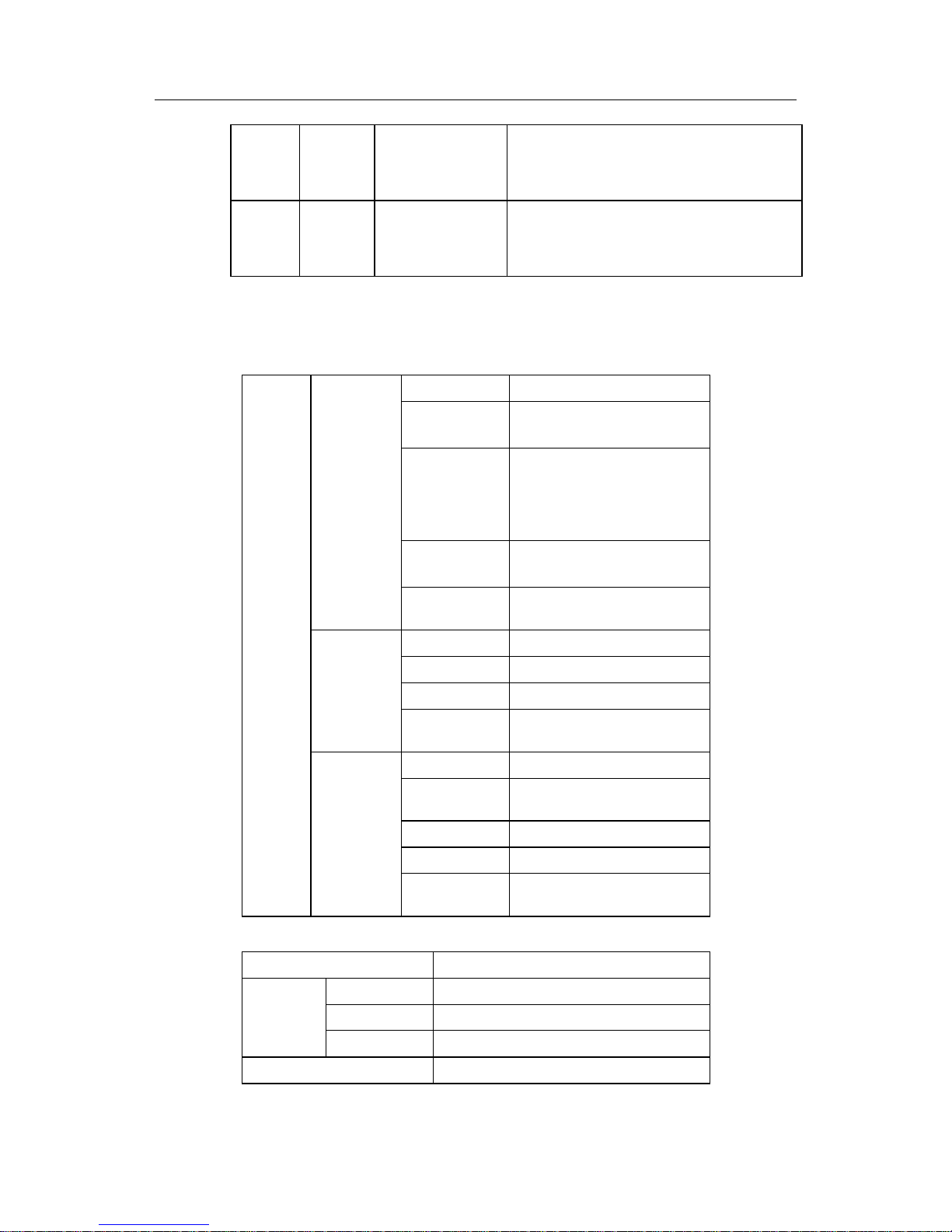
2. The specification of the rear panel
Figuer 2-2 Interface Distribution on Rear Panel of the DI-DI-2004
Switches and interfaces on the rear panel of the DI-2004 are shown in Figuer 2-2. The
specific meanings are in the followingTable 2-1.
Table 2-1 Component Functions on Rear Panel of the DI-DI-2004
Number Symbol Name Comment
1 Power Switch Push-up is on, and push-down is off
2 AC plug
3 Power
Data
Link
Indicator
From the top down, they are the power indicator, the
Ethernet data transfer indicator and the Ethernet
twisted-pair(TP) link interface indicator.
4 TP Ethernet TP port Connect LAN(Ethernet) through the port with TP
5 Console Console Port
Connect to terminals through the port to monitor and
deploy routers; the used line is the special Console
cable, and you can see connection specification in
Charter 2.3 “Port Connection Specification”.
- 7 -
Page 11
DI-2000 Series Routers hardware installation manual
6 Serial 0 Serial port 0
Connect to synchronous or asynchronous Modem.
The used line is the special monitoring cable, and
you can see connection specification in Charter 2.3
“Ports Connection Specification”.
7 Serial 1 Serial port 1
Connect to synchronous or asynchronous Modem.
The used line is the special monitoring cable, and
you can see connection specification in Charter 2.3
“Port Connection Specification”.
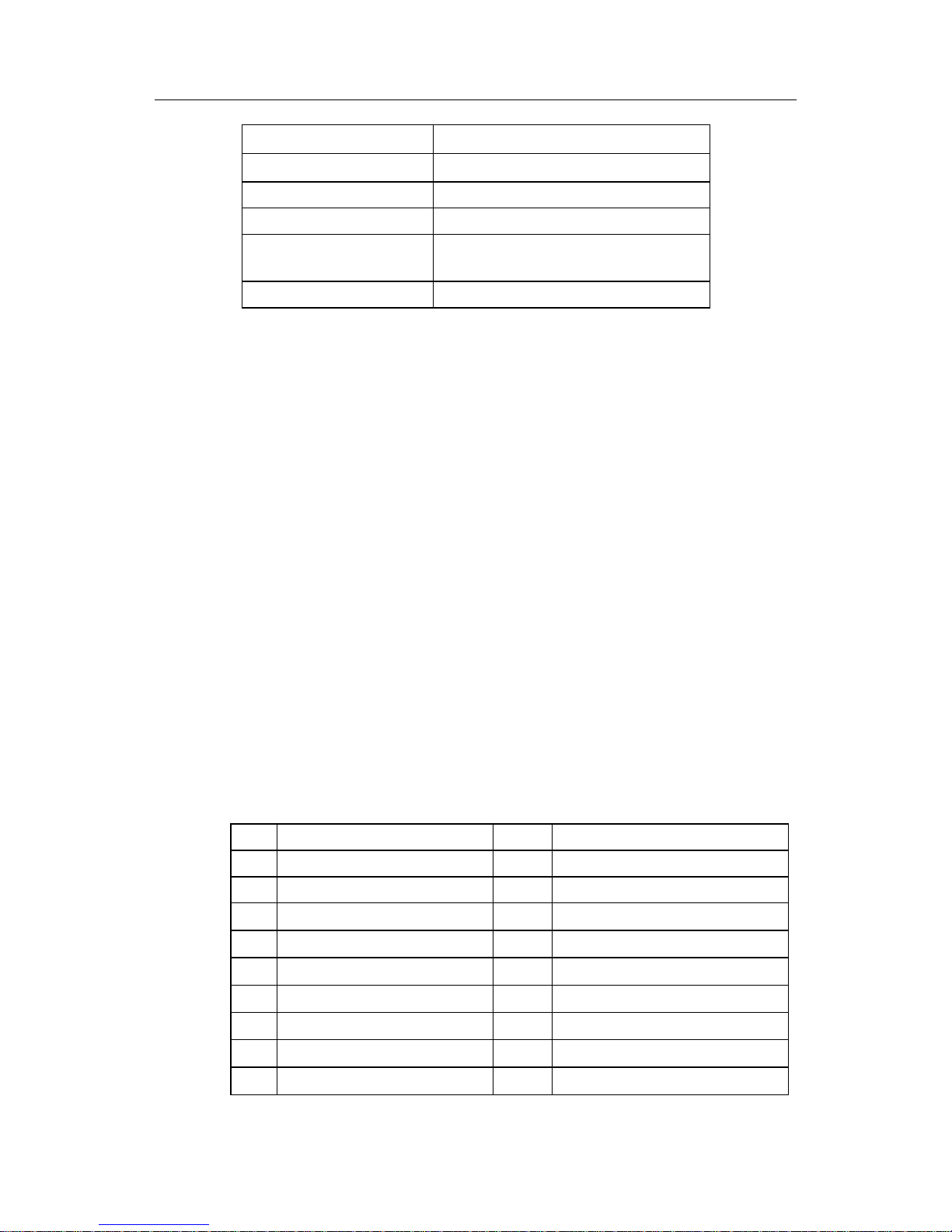
2.2 Hardware Technical Specifications
Table 2-2 Hardware Technical Specifications of the DI-2004 Router
Port amount
2 ports
The physical
layer protocols
V.24/V.28; RS232-D X.21bis; V.35;
RS422/RS449;
Port rate
Synchronization: RS-232 with a
maximum speed of 64Kbps; V.35
with a maximum speed of 2Mbps;
asynchronism:a maximum speed of
115Kbps.
Port protocols
X.25, X.32, FR, HDLC、SLIP,
PPP, ZMODEM*
Serial port
Physical
interface
high density jack with 44 pins and 3
rows
Port amount
1
Port Rate
10Mbps
Port protocols
The Ethernet protocol(IEEE 802.3)
Ethernet port
Physical
interface
TP port: RJ45
Port number
1
Physical layer
protocols
V.24/V.28; RS232-D; X.21bis
Port rate
9600bps
Port protocol
ZMODEM*
Port
Features
Console port
Physical
interface
RJ45
CPU
Motorola MC68EN360 33MHz
EPROM
256Kbyte
Flesh Memory
1-2Mbyte
Memory
DRAM
8Mbyte
Dimensions
341mm×248mm
- 8 -
Page 12
DI-2000 Series Routers hardware installation manual
Operating temperature
0℃ to 40℃
Nonoperating temperature
-20℃ to 65℃
Operating relative humi dity
10% to 85% noncondensing
Nonoperating relative humidity
5% to 95% noncondensing
Power
Input voltage:170 to 264 V;input frenquency :47
to 63Hz;input current: 0.2A/230V
Power dissipation
28W
Notice:
Protocols with * are supported only in system Console status.
2.3 Port Connection Specification
The DI-2004 router has two serial ports and one Ethernet port.
2.3.1 PIN description of each port on the DI-2004
1. The Serial Ports of the DI-2004 Router
The DI-2004 router has two serial ports. The jacks are three rows, 44 pins and high
density. The ports have the same PIN description. They can be deployed to be
synchronous or asynchronous methods, so they can connect to synchronous
MODEM(such as TAINET T-1496) or asynchronous MODEM(such as 3Com USR) for
entering special network. For synchronous method, the DI-2004 router also support
the physical protocol of V.35, capable of connecting to baseband MODEM(such as
ASCOM AM64000A ) with a maximum speed of 2Mbps to achieve the high-speed
access goal.
PIN Description of Serial Ports on the DI-2004 is shown as the following table:(PIN in
the table and figure is signed on corresponding location of the jack)
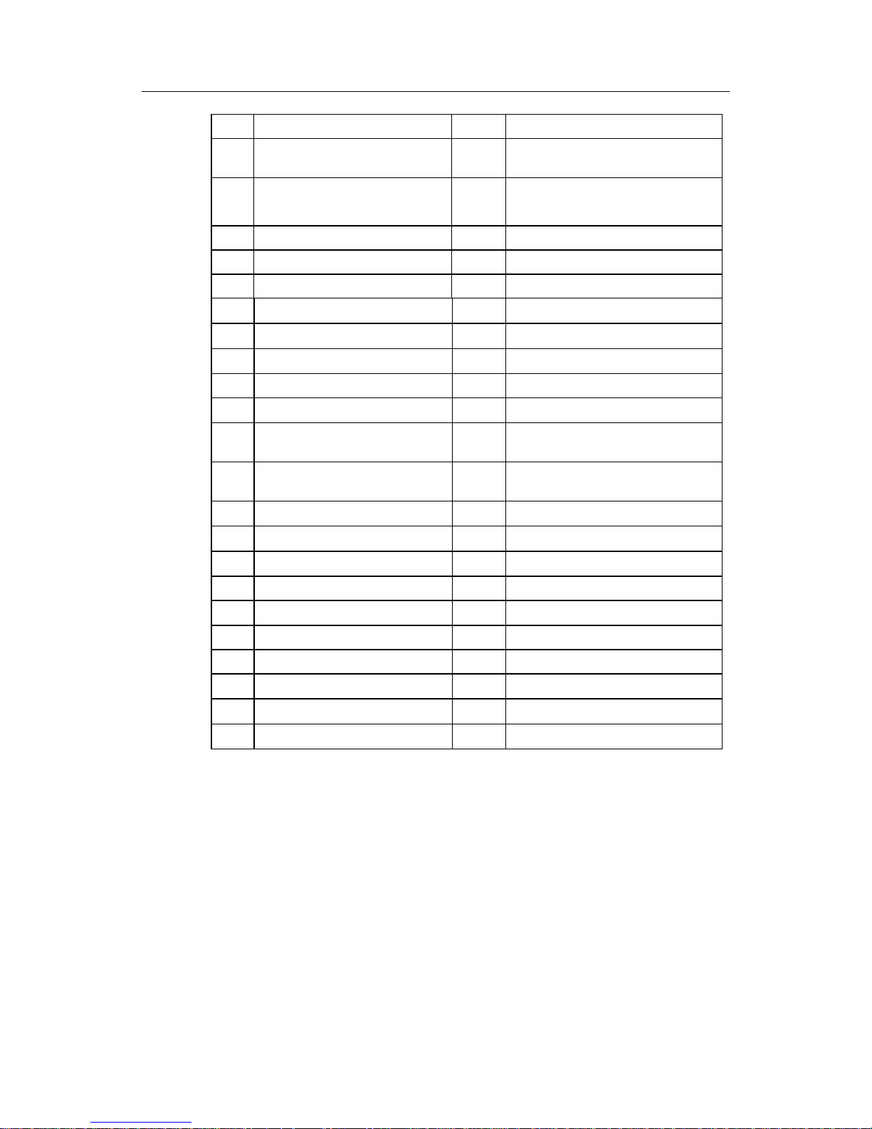
Table 2-3 PIN Description of Serial Ports
PIN Name Symbol Comment
1 Receive Clock RCLK Used for choosing V.28 or v.35
2 Transmit Clock TCLK Used for choosing V.28 or v.35
3 Transmit Data J_TXD
DTE→DCE; used for V.28
4 Receive Data J_RXD
DTE←DCE; used for V.28
5 Output Clock CLK232
DTE→DCE; used for V.28
6 Data Set Ready J_DSR
DTE←DCE; used for both V.28 and V.35
7 Clear To Send J_CTS
DTE←DCE; used for both V.28 and V.35
8 Transmit Clock (negative) TXC-
DTE←DCE; used for V.35
10 Receive Clock(negative) RXC-
DTE←DCE; used for V.35
- 9 -
Page 13
DI-2000 Series Routers hardware installation manual
11 External Receive Data RXDB Used for selecting V.35
13
Express Clock Output within A group
(negative)
ECLKA-
DTE→DCE; used for V.35
14
Express Clock Output within B group
(positive)
ECLKB+
DTE→DCE; used for V.35
16 External Receive Clock RXCA Used for selecting V.28
17 External Transmit Clock TXCA Used for selecting V.28
18 Internal Receive Data RXD Used for selecting V.28 or V.35
21 Carrier Detect J_CD
DTE←DCE; used for both V.28 and V.35
22 Request To Send J_RTS
DTE→DCE; used for both V.28 and V.35
23 Transmit Clock (positive) TXC+
DTE←DCE; used for V.35
24 Receive Clock RXCB Used for selecting V.35
26 Receive Data (positive) RXD+
DTE←DCE; used for V.35
27
Express Clock Output within A group
(positive)
ECLKA+
DTE→DCE; used for V.35
29
Express Clock Output within B
group(negative)
ECLKB-
DTE→DCE; used for V.35
30 Transmit Data TXD-
DTE→DCE; used for V.35
31 Receive Clock J_RXC
DTE←DCE; used for V.28
32 Transmit Clock J_TXC
DTE←DCE; used for V.28
33 Receive Data RXDA Used for selecting V.28
35 Data Terminal Ready J_DTR
DTE→DCE; used for both V.28 and V.35
36 Signal Ground SG Public signal ground of DTE and DCE
37 Transmit Clock TXCB Used for selecting V.35
39 Receive Clock (positive) RXC+
DTE←DCE; used for V.35
41 Receive Data (negative) RXD-
DTE←DCE; used for V.35
44 Transmit Data (positive) TXD+
DTE→DCE; used for V.35
Notice:
Other idle PINs should be connected to Signal Ground.
2. The Console port
The DI-2004 router has a Console port with the RJ45 jack. The port is connected to
terminals (such as STAR-510G
+
) or serial ports of PC with the special Console cable,
then terminal emulate software can be used to deploy and monitor the DI-2004 router.
Console PIN distribution is shown as:
- 10 -
Page 14

DI-2000 Series Routers hardware installation manual
Figuer 2-3 Pin distribution of RJ45
RJ45 plug and RJ45 jack is corresponding according to the ordinal number of 1 to 8
from the left to the right.
PIN description is shown in the following table.
Table 2-4 PIN Description of Console Port
PIN Name Symbol Comment
1 Carrier Detect CD Used for connection to MODEM
2 Receive Data RXD Input
3 Data Set Ready DSR Used for connection to MODEM
4 Transmit Data TXD Output
5 Request To Send RTS Used for connection to MODEM
7 Data Terminal Ready DTR Used for connection to MODEM
8 Signal Ground SG
3. Ethernet port
The Ethernet port of the DI-2004 router offers two physical interfaces:
AUI(Attachment Unit Interface) and TP interface(twisted-pair interface). While used,
the router can connect to HUB from TP interface through the twisted-pair cable, or the
router can connect to HUB, thin cable or thick cable from AUI through a special switch
box. PIN number order of TP interface is the same to Console port. Its distribution is as
Figuer 2-3.
Pin description of TP interface(twisted-pair interface) is shown as the following table.
Table 2-5 Pin description of TP Interface
PIN Name Symbol Comment
1 Transmit Data(positive) TPTXD+ Output
2 Transmit data (negative) TPTXD- Output
3 Receive Data (positive) TPRXD+ Input
4 Receive Data (negative) TPRXD- Input
PIN Description of AUI Interface is shown as the following Table 2-6.
- 11 -
Page 15

DI-2000 Series Routers hardware installation manual
Table 2-6 Pin Description of AUI Interface
PIN Name Symbol Comment
2 Collision Detect (positive) ACX+ Input
3 Send Data(positive) ATXD+ Output
5 Receive Data(positive) ARXD+ Input
9 Collision Detect(negative) ACX- Input
10 Transmit Data(negative) ATXD- Output
12 Receive Data(negative) ARXD- Input
13 Input positive 12V power PIN +12V Output
Notice
Other PINs are connected to Signal Ground.
2.3.2 External connection Specification of Ports
1. External connection Specification of Serial port
The router is connected to synchronous MODEM, asynchronous MODEM or baseband
MODEM supporting the physical protocol of V.28 protocol(or RS232 protocol)
according to Figuer 2-4.
Figuer 2-4 V.28 MODEM cable
When the serial port is connected to baseband MODEM supporting the physical
protocol of V.35, the connection figure is shown as Figuer 2-4.
The serial number of V.35 MODEM cable is DRC4211.
- 12 -
Page 16

DI-2000 Series Routers hardware installation manual
Figuer 2-5 V.35 MODEM cable
2. Extenal connection Specification of Console port
The cable connects the Console port of DI-2004 and external terminal Console devices.
One end is a 8 pin jack, and the other is a 25 aperture connector(DB25) and a 9
aperture connector(DB9). The RJ45 connector is plugged into the Console port of the
router, and among DB25 and DB9, one should be selected according to the
requirement of the terminal serial port. The internal connection of the cable is shown
as the following figure. The serial number of the Console cable is DRC0001.
Figuer 2-6 Console Cable Connection
3. External Connection Specification of AUI and TP interface
AUI port is also called thick Ethernet interface, through which the router can connect to
the thick cable with AUI cable, or connect to the thin cable or TP interface through the
special switch box.
TP port can connect five general types of twisted pair to HUB. Connect as shown
below:
- 13 -
Page 17

DI-2000 Series Routers hardware installation manual
Figuer 2-7 Ethernet TP Straight Cable Connection
- 14 -
Page 18

DI-2000 Series Routers hardware installation manual
Chapter 3 Introduction of the DI-2006 Router
3.1 Overview
The DI-2006 has a multi-protocol synchronous, asynchronous serial port and a ISDN
BRI port. Besides that, the router has a 10M Ethernet port(thick cable or thin cable
interface), with which business LANs can connect to Internet or DDN through ISDN,
PSTN, DDN, Frame Relay and X.25.
3.1.1 ISDN BRI interface
D channel: Call Control Signaling and DSS1(Digital Subscriber Signaling
System)( Q.921,Q.931) comply with Chinese national standard and European
standard(ETSI).
B channel: support PPP(including PAP and CHAP secure identification and supporting
PPP compression), Frame Relay, and X.25.
3.1.2 WAN interface
Physical interface: V.24/V.28、 V.35
Synchronous rate: 2Mbps
Asynchronous rate: 115Kbps
Supporting protocols: X.25, X.32, Frame Relay, SLIP and PPP
3.1.3 Ethernet port
Physical interface: V.24/V.28 and V.35
Rate: 10 Mbps
Supporting protocols: V.24/V.28 and V.35
3.1.4 Console port
Physical Interface: RJ45, and (EIA-RS232C)
Rate: 9600bps
Supporting Protocols: Z-Modem
- 15 -
Page 19

DI-2000 Series Routers hardware installation manual
3.1.5 Processor
Motorola 68EN360@33Mhz
3.1.6 Memory
EPROM: 256KByte
FLASH RAM: 2Mbyte. It can be enlarged to Mbyte.
DRAM: 8MByte
3.1.7 Features
The router supports multiple network protocols with strong function.
The application layer: TELNET, X.29 and TFTP
The transport and network layers: TCP, UDP, IP, ICMP, ARP and NAT
The data link layer: SLIP, PPP, X25, Frame Relay, HDLC and ETHERNET
Dynamic routing: RIP1, RIP2 and OSPF
Network management protocol: SNMP v1&v2
ISDN:Supports Q.921,Q.931, Chinese national standard and European standard
(ETSI).
Support ten types switches from North America, Europe, Australia and Japan.
The router can realize backup by completely using static routing through our unique
E-BACKUP technology in order to improve communication efficiency, decrease
communication cost and switch automatically.
The router supports multi-level user permission and remote user identification to
prevent unauthorized users’ attack on routers and networks;
The router supports firewall function based on packet filtering and ACL technology to
filter data packet passing routers.
The router supports NAT function of hiding internal network structure to improve
network security.
The power consumes less than 50W.
- 16 -
Page 20

DI-2000 Series Routers hardware installation manual
3.2 Exterior Specification of the DI-2006
3.2.1 Exterior Specification
1. The Front Panel of the DI-2006
Figuer 3-1 The Front Panel of the DI-2006
2. The Rear Panel of the DI-2006
Figuer 3-2 Rear Panel Interface Distribution of the DI-2006
Switches and interfaces on the rear panel of the DI-2006 are shown as Figuer 3-2
meanings of which are shown as Table 3-1.
Table 3-1 The rear panel specification of the DI-2006
Number Symbol Name Comment
1 Power Switch Push-up is on, and push-down is off
2 AC Plug
3 Power
Data
Link
Indicator
From the top down, they are the power indicator, the
Ethernet data transfer indicator and the Ethernet
twisted-pair link interface indicator.
4
TP
Ethernet TP
Interface
Connect LAN(Ethernet) through the port with TP
5 Console Console Port
Connect to terminals through the port to monitor and
deploy routers; the used line is the special Console
cable, and you can see connection specification in
Charter 2.3 “Ports Connection”.
6 Serial 0 Serial Port 0
Connect to synchronous or asynchronous Modem.
The used line is the special monitoring cable, and
you can see connection specification in Charter 2.3
“Ports Connection Specification”.
- 17 -
Page 21

DI-2000 Series Routers hardware installation manual
7 BRI S/T
ISDN BRI S/T
interface
Connect to S/T interface( RJ45) of ISDN network
terminal(NT1) through the port
8 ACTIVE
ISDN BRI S/T
interface is active
When the line is enabled and D channel is active, the
indicator will glint.
9 TR
Selective switches
of 100Ω terminal
resistance
TR should be set as ON under point-to-point
communication. TR of two general bus terminal
should be set as ON under general bus
communication , while other DI-2006 routers should
be set as OFF.
3.3 Port Connection Specification
3.3.1 PIN Specification of Ports
The DI-2006 router has a serial port, a Ethernet port and a ISDN S/T interface. PIN
description of each port is as follows:
1. Serial ports
The DI-2006 router has one serial port. The jacks are three rows, 44 pins and high
density. They can be deployed to be synchronous or asynchronous methods, so they
can connect to synchronous MODEM(such as TAINET T-1496) or asynchronous
MODEM(such as 3Com USR) for entering special networks. For synchronous method,
the DI-2004 router also support the physical protocol of V.35, capable of connecting to
baseband MODEM(such as ASCOM AM64000A ) with a maximum speed of 2Mbps to
achieve the high-speed access goal.
PIN description of serial ports on the DI-2006 is shown asTable 3-1:( PIN in the table
and figure is signed in corresponding location of the jack)
2. The Console port
The DI-2006 router has a Console port with the standard RJ45 jack. The port is
connected to terminals(such as STAR-510G
+
) or serial ports of PC with the special
Console cable, then terminal emulate software can be used to deploy and monitor the
DI-2006 router.
Pin description is shown as Figuer 2-3.
3. Ethernet port
The Ethernet port of the DI-2006 router offers two physical interfaces:
AUI(Attachment Unit Interface) and TP interface(twisted-pair interface). While used,
the router can connect to HUB from TP interface through twisted-pair cable, or the
router can connect to HUB, thin cable or thick cable from AUI through a special switch
box. Pin number order of TP interface is the same to Console port. Its distribution is
shown as Figure 1-2-3.
Pin description of TP interface(twisted-pair interface) is shown as Table 2-5.
- 18 -
Page 22

DI-2000 Series Routers hardware installation manual
Pin description of AUI(Attachment Unit Interface) is shown as Table 2-6.
4. ISDN S/T Interface of the DI-2006 router
Table 3-2 PIN description of ISDN S/T Interface(RJ45 interface) is as shown below:
PIN Name Symbol Comment
3 Transmit Data (positive) TXD+ Output
4 Receive Data(positive) RXD+ Input
5 Receive Data(Negative) RXD- Input
6 Transmit Data(Negative) TXD- Output
3.3.2 External connection Specification of Serial Ports on the DI-2006
1. External Connection Specification of Serial port on the DI-2006
The router is connected to synchronous MODEM, asynchronous MODEM or baseband
MODEM supporting the physical protocol of V.28 protocol(or RS232 protocol)
according toFiguer 2-4.
When the serial port is connected to baseband MODEM supporting the physical
protocol of V.35, the connection figure is as Figuer 2-5.
The serial number of V.35 MODEM cable is DRC4211.
2. External Connection Specification of Console port on the DI-2006
The cable connects the Console port of DI-2006 and external terminal Console devices.
One end is a 8 pin jack, and the other is a 25 aperture connector(DB25) and a 9
aperture connector(DB9). The RJ45 connector is plugged into the Console port of the
router, and among DB25 and DB9, one should be selected according to the
requirement of the terminal serial port. The internal connection of the cable is shown
as Figuer 2-6. The serial number of the Console cable is DRC0001.
3. External Connection Specification of AUI and TP interface on the DI-2006
AUI port is also called thick Ethernet interface, which can connect to the thick cable
with AUI cable. AUI port can also connect to the thin cable, or TP interface, the
Ethernet RJ45 port, through the special switch box.
TP port can connect general five types of twisted pair to HUB. Connect as shown in
Figuer 2-7:
4. External Connection Specification of ISDN S/T Interface on the DI-2006
With straight RJ45 line, network terminal NT1 connects to ISDN BR1 S/T interface.
Straight RJ45 Line is shown as the following figure:
- 19 -
Page 23

DI-2000 Series Routers hardware installation manual
Figuer 3-3 Straight RJ45 Line
5. Cross Cable Connection Specification for Debugging
(1) cross cable on the Serial port
Under certain conditions, two serial ports of a DI-2000 series of router needs to
be crossed, or two DI-2000 series of routers connect back on the back according
to the following connection methods.
Select V.28 (RS-232)method on the port as shown below:
Figuer 3-4 V.28 Cross Cable Usage
V.28 cross cable connection is show as Figure 1-3-5.
Figuer 3-5 V.28 Cross Cable Connection
- 20 -
Page 24

DI-2000 Series Routers hardware installation manual
Use V.35 method as Figuer 3-6.
Figuer 3-6 V.35 Cross Cable Usage
V.28 cross cable connection is shown asFiguer 3-7.
Figuer 3-7 V.35 Cross Cable Connection
(2) Cross Cable on the Ethernet Port
Two DI-2000 series of routers can be across interconnected with TP cross cable
or AUI cross cable. TP cross cable can be used on straight connection of a
router and the TP interface of a single host LAN card. Such, a HUB can be
saved in a LAN. But a HUB is necessary when more than two Ethernet TP ports
are interconnected.
Connect two Ethernet ports(TP ports) with the TP cross cable.
- 21 -
Page 25

DI-2000 Series Routers hardware installation manual
TP cross cable connection is shown as Figure 1-3-8.
Figuer 3-8 Ethernet TP Cross Cable Connection
Connect two Ethernet Ports (thicknet ports) with AUI cross cable
AUI cross cable connection is shown as Figuer 3-9.
Figuer 3-9 Ethernet AUI Cross Cable Connection
- 22 -
Page 26

DI-2000 Series Routers hardware installation manual
Chapter 4 Installation of the Routers
4.1 Installation Specification
Figuer 4-1 Installation Figure of the DI-2000 Series
Installation steps of the DI-2000 is shown as numbers of Figuer 4-1.
(1) Install the upper panel from the top down. Ensure mesh between teeth of frames
and edges of the nether panel .
(2) Push the upper panel from the front back and ensure mesh between the back
edge of the upper panel and the upper edge of the nether panel.
(3) Fix screws on the nether edge of the two sides on the upper panel. ③ in the
figure only shows the right side, the same to the left.
Notice:
Danger! Within the router, there is dangerous voltage harmful to people. Don’t open the panel except
maintenance organizations authorized by company. Or else, all serious results should be assumed by
self.
4.2 Mount the Routers in a Standard Rack
There are two methods to attach brackets to the DI-2000 Series of routers as shown in
Figuer 4-2 and Figuer 4-3 For the first method, first use screws to fix brackets on the
two sides of the DI-2000 Series with the front panel forward (Figuer 4-2 only shows the
right attachment, the same to the left). Then attach brackets to the rack according to
Figuer 4-4.. For the second mounting method, use screws to fix brackets on the two
sides of the DI-2000 Series with the rear panel forward (Figuer 4-3 only shows the right
attachment, the same to the left). Then attach brackets to the rack according to Figuer
4-4.
Figuer 4-2 The First Attaching-Brackets Method
- 23 -
Page 27

DI-2000 Series Routers hardware installation manual
- 24 -
Figuer 4-3 The Second Attaching-Brackets Method
Figuer 4-4 Attaching Brackets to the Rack
Notice:
Please notice the following points when using the DI-2000 series:
1) As other electronic devices, Starting and turning off the power fast and frequently does harm to
semiconductor chips; when needing to restart the DI-2000 series of routers, please turn on the
power again after an interval of 3 to 5 seconds from turning off the power.
Please try to use the “reboot” command to restart the routers.
2) Please don’t bump the routers or make the DI-2000 series fall from high. Such operations may
harm the internal hardware of the routers.
3) Please connect to the DI-2000 series with correct exterior connection ports. Don’t plug the
telephone plug(RJ11, a 4-line plug) into the Ethernet TP port or Console port. Ethernet TP jack
can’t be plugged into the Console port(RJ45, a 8-line jack). And the Console port cable can’t be
plugged into the Ethernet TP port(RJ45, a 8-line jack). The above and other mistaken operations
may harm internal components of the port.
Page 28

DI-2000 Series Routers hardware installation manual
Warranty and Registration Information
(All countries and regions excluding USA)
Wichtige Sicherheitshinweise
1. Bitte lesen Sie sich diese Hinweise sorgfältig durch.
2. Heben Sie die se Anleitung für den spätern Gebrauch auf.
3. Vor jede m Reinigen ist das G erät vom Stromnetz zu tre nnen. Vervenden S ie keine Flüssi g- oder Aerosolrein iger. Am besten dient ein angefeuchtetes Tuch zur Reinigung.
4. Um eine Beschädigung des Gerätes zu vermeiden sollten Sie nur Zubehörteile verwenden, die vom Hersteller zugelassen sind.
5. Das Gerät is vor Feuchtigkeit zu schützen.
6. Bei der Aufstellung des Gerätes ist auf sichern Stand zu achten. Ein Kippen oder Fallen könnte Verletzungen hervorrufen. Verwenden Sie nur sichere Standorte und
beachten Sie die Aufstellhinweise des Herstellers.
7. Die Bel üftungsöffnunge n dienen zur Lu ftzirkulation die das Gerät vor Überh itzung schützt. So rgen Sie dafür, daß d iese Öffnungen nicht abgedeckt werden.
8. Beachten Sie beim Anschluß an das Stromnetz die Anschlußwerte.
9. Die Netzanschlußsteckdose muß aus Gründen der elektrischen Sicherheit einen Schutzleiterkontakt haben.
10. Verlegen Sie die Netzanschlußle itung so, daß niemand darüber fallen kann. Es s ollete auch ni chts auf der Leitu ng abgestellt werde n.
11. Alle Hinweise und Warnungen die si ch am Geräten befinden sind zu beachten.
12. Wird das Gerät über einen längeren Zeitraum nicht benutzt, sollten Sie es vom Stromnetz trennen. Somit wird im Falle einer Überspannung eine Beschädigung
vermieden.
13. Durch die Lüftungsöffnungen dürfen niemals Gegenstände oder Flüssigkeiten in das Gerät gelangen. Dies könnte einen Brand bzw. Elektrischen Schlag auslösen.
14. Öffnen Sie niemals das Gerät. Das Gerät darf aus Gründen der elektrischen Sicherheit nur von authorisiertem Servicepersonal geöffnet w erden.
15. Wenn folgende Situationen auftreten ist das Gerät vom Stromnetz zu trennen und von einer qualifizierten Servicestelle zu überprüfen:
a. Netzkabel oder Netzstecker sint beschädig t.
b. Flüssigkeit ist in das Gerät eingedrungen.
c. Das Gerät war Feuchtigkeit ausgesetzt.
d. Wenn das Gerät nicht der Bedienungsanleitung ensprechend funktioniert oder Sie mit Hilfe dieser Anleitung keine Verbesserung erzielen.
e. Das Gerät ist gefallen und/oder das Gehäuse ist beschädigt.
f. Wenn das Gerät deutliche Anzeichen eines Defektes aufweist.
16. Bei Reparaturen dürfen nur Orginalersatzteile bzw. den Orginalteilen entsprechende Teile verwendet werden. Der Einsatz von ungeeigneten Ersatzteilen kann eine weitere
Beschädigu ng hervorrufen.
17. Wenden Sie sich mit allen Fragen die Service und Repartur betreffen an Ihren Servicepartner. Somit stellen Sie die Betriebssicherheit des Gerätes sicher.
18. Zum Netzanschluß dieses Gerätes ist eine geprüfte Leitung zu verwenden , Für einen Nennstrom bis 6A und eine m Gerätegewicht grőßer 3kg ist eine Lei tung nicht leichte r
als H05VV-F, 3G, 0.75mm2 einzusetzen.
WARRANTIES EXCLUSIVE
IF THE D-LINK PRODUCT DOES NOT OPERATE AS WARRANTED ABOVE, THE CUSTOMER'S SOLE REMEDY SHALL BE, AT D-LINK'S OPTION, REPAIR OR REPLACEMENT.
THE FOREGOING WARRANTIES AND REMEDIES ARE EXCLUSIVE AND ARE IN LIEU OF ALL OTHER WARRANTIES, EXPRESSED OR IMPLIED, EITHER IN FACT OR BY
OPERATION OF LAW, STATUTORY OR OTHERWISE, INCLUDING WARRANTIES OF MERCHANTABILITY AND FITNESS FOR A PARTICULAR PURPOSE. D-LINK NEITH ER
ASSUMES NOR AUTHORIZES ANY OTHER PERSON TO ASSUME FOR IT ANY OTHER LIABILITY IN CONNECTION WITH THE SALE, INSTALLATION MAINTENANCE OR US E OF
D-LINK'S PRODUCTS.
D-LINK SHALL NOT BE LIABLE UNDER THIS WARRANTY IF ITS TESTING AND EXAMINATION DISCLOSE THAT THE ALLEGED DEFECT IN THE PRODUCT DOES NOT EXI ST
OR WAS CAUSED BY THE CUSTOMER'S OR ANY THIRD PERSON'S MISUSE, NEGLECT, IMPROPER INSTALLATION OR TESTING, UNAUTHORIZED ATTEMPTS TO REPA IR, OR
ANY OTHER CAUSE BEYOND THE RANGE OF THE INTENDED USE, OR BY ACCIDENT, FIRE, LIGHTNING OR OTHER HAZARD.
LIMITATION OF LIABILITY
IN NO EVENT WILL D-LINK BE LIABLE FOR ANY DAMAGES, INCLUDING LOSS OF DATA, LOSS OF PROFITS, COST OF COVER OR OTHER INCIDENTAL, CONSEQUENTIAL OR
INDIRECT DAMAGES ARISING OUT THE INSTALLATION, MAINTENANCE, USE, PERFORMANCE, FAILURE OR INTERRUPTION OF A D- LINK PRODUCT, HOWEVER CAUSED
AND ON ANY THEORY OF LIABILITY. THIS LIMITATION WILL APPLY EVEN IF D-LINK HAS BEEN ADVISED OF THE POSSIBILITY OF SUCH DAMAGE.
IF YOU PURCHASED A D-LINK PR ODUCT IN TH E UNITED STA TES, SOME S TATES DO N OT ALLOW THE L IMITATI ON OR EXCLUS ION OF LIAB ILITY FOR INCIDENTAL O R
CONSEQ UENTIAL DA MAGES, SO THE ABOVE LI MITATION MAY NOT AP PLY TO YOU .
Limited Warranty
Hardware:
D-Link warrants ea ch of its hardware products to be free from defects in workman ship and materials under normal use and service for a perio d commencing on the date of
purchase from D-Link or its Authorized Reseller and extending for the length of time stipulated by the Authorized Reseller or D-Link Branch O ffice nearest to the place of
purchase.
This Warranty applies on the condition that the product Registration Card is filled out and returned to a D-Link office within ninety (90) da ys of purchase. A list of D-Link off ices
is provided at the back of this manu al, together with a copy of the Regi stration Card.
If the product proves defective within the applicable warranty period, D-Link will provide repair or replacement of the product. D-Link shall have the sole discretion whether to
repair or replace, and replacement product may be new or reconditioned. Replacement product shall be of equivalent or better specifications, relative to the defective product, but
need not be ide ntical. Any product o r part repaired by D-L ink pursuant to this warran ty shall have a warranty period of not less than 90 day s, from date of such repair,
irrespective of any earlier expiration of original warranty period. When D-Link provides replacement, then the defective product becomes the property of D-Link.
Warranty service may be obtained by contacting a D-Link office within the applicable warranty period, an d requesting a Return Material Authorization (RMA) number. If a
Registration Card for the product in question has not been returned to D-Link, then a proof of purchase (such as a copy of the dated purchase invoice) must be provided. If
Purchaser's circumstan ces require special handling of warranty correction, then at the time of requesting RMA number, Purchaser may also propose special procedure as may be
suitable to the case.
After an RMA number is issued, the defective product must be packaged securely in the original or other suitable shipping package to ensure that it will not be damaged in
transit, and the RMA number must be prominently marked on the outside of the package. The package must be mailed or otherwise shipped to D-Link with all costs of
mailing/shipping/ins urance prepaid. D-Link shall ne ver be responsible for an y software, firmware, informat ion, or memory data of Purc haser contained in, store d on, or
integrated with any product returned to D-Link pursuant to thi s warranty.
Any package returne d to D-Link without an RMA numbe r will be rejected and ship ped back to Purchaser at Purchase r's expense, and D-Link reserves the ri ght in such a cas e to
levy a reasonable handling charge in addition mailing or shipping costs.
Software:
Warranty service for software products may be obtained by contacting a D-Link o ffice within the applicable warranty period. A lis t of D-Link offices is pro vided at the back of thi s
manual, together with a copy of the Registration Card. If a Registration Card for the product in question has not been returned to a D-Link office, then a proof of purchase (such
as a copy of t he dated purchase invoice ) must be provided whe n requesting warranty serv ice. The term "purchase" in this software warranty refers to the purchase transaction
and resulting license to use such software.
D-Link warrants t hat its software products w ill perform in substantial conformance with the applicable product documentation provided by D-Link with such software product,
for a period of ninety (90) days from the date of purchase from D-Link or its Authorized Reseller. D-Link warrants the magnetic media, on which D-Link provides its software
product, against fai lure during the same warranty period. This warranty applie s to purchased software, and to replacement software provided by D-Link pursuant to this
warranty, but shall not apply to any update or replacement which may be provided for download via the Internet, or to any update which may otherwise be provided free of charge.
D-Link's sole obligation under this software warranty shall be to replace any defective software product with product which substantially conforms to D-Link's applicable product documentation. Purchaser assumes
responsibility for the selection of appropriate application and system/platform software and associated reference materials. D-Link makes no warranty that its software products will work in combination with any hardware, or
- 25 -
Page 29

DI-2000 Series Routers hardware installation manual
any application or system/platform software product provided by any third party, excepting only such products as are expressly represented, in D-Link's applicable product documentation as being compatible. D-Link's
obligation under this warranty shall be a reasonable effort to provide compatibility, but D-Link shall have no obligation to provide compatibility when there is fault in the third-party hardware or software. D-Link makes no
warranty that operation of its software products will be uninterrupted or absolutely error-free, and no warranty that all defects in the software product, within or without the scope of D-Link's applicable product documentation,
will be corrected.
- 26 -
Page 30

DI-2000 Series Routers hardware installation manual
Subject to the terms and conditions set forth her ein, D-Link Systems, I nc. (“D-Link”) provi des this Limited warranty for its product only to the person or entit y that originally pur chased the product
from:
• D-Link or its authorized reseller or distributor and
• Products purchased and delivered within the fifty states of the United States, the Distric t of Columbia, U.S. Possessions or Protec torates, U.S. Military Installations, addresses wit h an APO
or FPO.
Limited Warranty: D-Link warrants that the har dware port i on of the D-Link pr oducts descri bed bel ow will be free from material defects in workmanship and materials from the date of original retail
purchase of the product, for the period set forth below applicable to the product type (“Warranty Per iod”), except as otherwise stated herein.
Limited Lifetime Warranty for the Product(s) is defined as follows:
• Hardware for as long as the original c ustomer/end user owns the product, or five years after product discontinuance, whichev er oc c ur s first (excluding power supplies and fans)
• Power Supplies and Fans Three (3) Year
• Spare parts and spare kits Ninety (90) days
D-Link’s sole obligation shall be t o repair or replace the def ective Hardware during t he Warranty Period at no charge t o the original owner or t o refund at D-Link’s sole di scretion. Such repai r or
replacement will be rendered by D-Link at an Authorized D-Link Service Office. The replacement Hardware need not be new or have an identic al make, model or part . D-Link may in its sol e
discretion replace the defective Hardware (or any part thereof) with any reconditioned product that D-Link reasonably determines is substantially equivalent ( or superior) in all material respects to the
defective Hardware. Repaired or replacement Hardware will be warranted f or the remainder of t he original Warranty P eriod from the dat e of original retail purchase. If a material def ect is incapabl e
of correction, or if D-Link determines in its sole discretion t hat it is not practi cal to repair or replace the def ectiv e Hardware, the price paid by the original purchaser for the defective Hardware will be
refunded by D-Link upon return to D-Link of the defective Hardware. All Hardware (or par t thereof ) that is replaced by D- Li nk, or for which the purchase pric e is refunded, shall become the proper ty
of D-Link upon replacement or refund.
Limited Software Warranty: D-Link warrants that t he software portion of the product (“Soft ware”) will substantially conform to D-Link’s then current functional specifications for the Software, as set
forth in the applicable document ation, f rom the date of origi nal ret ail purchase of t he Software f or a peri od of ninet y (90) days (“W arrant y Period” ), provi ded that t he Software i s properl y i nstalled on
approved hardware and operated as contemplat ed in its documentation. D- Link further warrants that, during the Warrant y Period, the magnetic m edia on which D-Link delivers the Software wil l be
free of physical defects. D-Link’s sole obli gation shall be to replace the non-conf orming Software (or def ective media) with software that substantiall y conforms to D-Link’s f unctional specifi cations
for the Software or to refund at D-Link’s sole di scretion. Except as otherwise agreed by D-Li nk in writi ng, the replacement Software i s provided only to the origi nal licensee, and is subject to t he
terms and conditions of the license granted by D-Link for the Software. Software wil l be warranted for the remainder of the ori ginal Warranty Period from the date or original r etail purchase. If a
material non-conformance is incapable of correcti on, or if D-Link determi nes in its sole discreti on that it is not practi cal to replac e the non-conformi ng Soft ware, the pric e paid by the original licensee
for the non-conforming Software will be refunded by D-Link; provided that the non-conf orming Software (and all copies thereof) is first returned to D-Link. The license grant ed respecting any
Software for which a refund is given automatical ly terminates.
Non-Applicability of Warranty: The Limited Warranty provided her eunder for hardware and software of D-Link's products will not be applied to and does not cov er any refur bished product and any
product purchased through the inv entory clearance or liquidati on sale or other sales in which D-Li nk, the sellers, or the li quidators expressly disclaim t heir warranty obligation pert aining to the
product and in that case, the product is being sold "As-Is" without any warranty whatsoever including, without limitation, the Limited Warranty as descri bed herein, notwithstanding anythi ng stated
herein to the contrary.
Submitting A Claim: The customer shall return the product to the original purchase point based on its return policy. In case the return polic y period has expired and the produc t is within warrant y,
the customer shall submi t a claim to D-Link as outlined below:
• The customer must submit with the product as part of the claim a written descripti on of the Hardware defect or Software nonconf ormance in sufficient det ail to allow D-Link to confirm the
same.
• The original product owner must obtain a Return Material Aut horizati on (“RMA” ) number from the Authori zed D-Link Servic e Office and, if requested, pr ovi de written pr oof of purchase of t he
product (such as a copy of the dated purchase invoice for the product) before the warranty service is provided.
• After an RMA number is issued, the defective product must be pac kaged securely in t he original or other suitable shipping packa ge to ensure that it will not be damaged in transit, and t he
RMA number must be prominently marked on the outside of the package. Do not include any manuals or accessories in the shipping package. D-Link will only replace the def ective porti on
of the Product and will not ship back any accessories.
• The customer is responsible for all in-bound shipping charges to D-Link. No Cash on Delivery (“COD”) is allowed. Products sent COD will either be rejected by D-Link or become the
property of D-Link. Products shall be fully insured by the customer and shipped to D-Link Systems, Inc., 17595 Mt. Herrmann, Fountain Valley, CA 92708. D-Link will not be held
responsible for any packages that are lost in transit to D-Link. The repaired or replaced packages will be shipped to the customer via UPS Ground or any common carrier selec ted by D-Link,
with shipping charges prepaid. Ex pedited shipping is available i f shipping charges are prepaid by the customer and upon request.
D-Link may reject or return any product that is not pac kaged and shipped in stri ct compli ance with the foregoing r equirements, or for which an RMA num ber is not visible fr om the outside of t he
package. The product owner agrees to pay D-Link’s r easonable handling and return shipping charges for any product that i s not packaged and shipped in accordance with the foregoing
requirements, or that is determined by D-Link not to be defective or non-conforming.
What Is Not Covered: This limited warranty provided by D-Li nk does not cover: Products, if in D-Li nk’s judgment, have been subjected to abuse, ac cident, alteration, modific ation, tampering,
negligence, misuse, faulty installation, l ack of reasonable care, repair or service in any way that is not contemplated in the documentati on for the product, or if the model or serial number has been
altered, tampered with, defaced or removed; Initial instal l ation, install ation and r emoval of the product for repair , and shippi ng costs; Operational adj ustm ents covered in the operati ng manual for the
product, and normal maintenance; Damage that occurs in shipm ent, due to act of God, failur es due to power surge, and co smetic dam age; Any hardware, soft ware, firm ware or other product s or
services provided by anyone other t han D-Link; Products that hav e been purchased from i nventory clearance or liqui dation sales or other sales in whic h D-Link, the sellers, or the liquidators
expressly disclaim their warranty obligation pertaini ng to the product. Repair by anyone other than D-Link or an A uthorized D-Link Service Office will void this Warranty.
Disclaimer of Other Warranties: EXCEPT FOR THE LIMITED WARRANTY SPECIFIED HEREIN, THE PRODUCT IS PROVIDED “AS-IS” WITHOUT ANY WARRANTY OF ANY KIND
WHATSOEVER INCLUDING, WITHOUT LIMITATION, ANY WARRA NTY OF MERCHANTABILITY, FITNESS FOR A PARTICULAR PURPOSE AND NON-I NFRINGEMENT. IF ANY IMPLIED
WARRANTY CANNOT BE DISCLAIMED IN ANY TERRITORY WHERE A PRODUCT IS SOLD, THE DURATION OF SUCH IMPLIED WARRANTY SHALL BE LIMITED TO NINETY (90) DAYS.
EXCEPT AS EXPRESSLY COVERED UNDER THE LIMITED WARRANTY PROVIDED HEREIN, THE ENTIRE RISK AS TO THE QUALITY, SELECTION AND PERFORMANCE OF THE
PRODUCT IS WITH THE PURCHASER OF THE PRODUCT.
- 27 -
Page 31

DI-2000 Series Routers hardware installation manual
Limitation of Liability: TO THE MAXIMUM EXTENT PERMITTED BY LAW, D-LINK IS NOT LIABLE UNDER ANY CONTRACT, NEGLIGENCE, STRICT LIABILITY OR OTHER LEGAL OR
EQUITABLE THEORY FOR ANY LOSS OF USE OF THE PRODUCT, INCONVENIENCE OR DAMAGES OF ANY CHARACTER, WHETHER DIRECT, SPECIAL, INCIDENTAL OR
CONSEQUENTIAL (INCLUDING, BUT NOT LIMITED TO, DAMAGES FOR LOSS OF GOODWILL, LOSS OF REVENUE OR PROFIT, WORK STOPPAGE, COMPUTER FAILURE OR
MALFUNCTION, FAILURE OF OTHER EQUIPMENT OR COMPUTER PROGRAMS TO WHICH D- LINK’S PRODUCT IS CONNECTED WITH, LO SS OF INFORMATION OR DATA CONTAINED
IN, STORED ON, OR INTEGRATED WITH ANY PRODUCT RETURNED TO D-LI NK FOR WARRANTY SERVICE) RESULTING FROM THE USE OF THE PRODUCT, RELATING TO
WARRANTY SERVICE, OR ARISING OUT OF ANY BREACH OF THIS LIMITED WARRANTY, EVEN IF D-LINK HAS BEEN ADVISED OF THE POSSIBILITY OF SUCH DAMAGES. THE SOLE
REMEDY FOR A BREACH OF THE FOREGOING LIMITED WARRANTY IS REPAIR, REPLACE MENT OR REFUND OF THE DEFECTIV E OR NON-CONFORMING PRODUCT. THE MAXIMUM
LIABILITY OF D-LINK UNDER THIS WARRANTY IS LIMITED TO THE PURCHASE PRICE OF THE PRODUCT COVERED BY THE WARRANTY. THE FOREGOING EXPRESS WRITTEN
WARRANTIES AND REMEDIES ARE EXCLUSIVE AND ARE IN LIEU OF ANY OTHER WARRANTIES OR REMEDIES, EXPRESS, IMPLIED OR STATUTORY
Governing La w: This Limited Warranty shall be governed by the laws of the St ate of California. Some states do not allow exclusion or lim itation of incidental or consequential damages, or
limitations on how long an implied warranty lasts, so the foregoi ng limit ations and exclusi ons may not apply. Thi s limit ed warranty provides specif ic legal ri ghts and the product owner m ay also have
other rights which vary from state to state.
Trademarks: D-Link is a registered trademark of D-Link System s, Inc. Other trademarks or registered trademarks are the property of their respecti ve manufacturers or owners.
Copyright Statement: No part of this publication o r document ation accomp anying this P roduct may be repro duced in an y form or by any means or used to make any derivat ive such as
translation, transformation, or adap tation without permission from D-Link Corpo ration/D-Link Systems, Inc., as stip ulated by the United States Copyright Act of 1976. Content s are
subject to change without prior notice. Copyright
©
2002 by D-Link Corporati on/D-Link Systems, Inc. All rig hts reserved.
CE Mark Warning: This is a Cl ass A product . In a domestic environment, this product may cause radio interference, in which case the user may be required to take adequate measures.
FCC Statement: This equipment has been tested and found to comply with the limits for a Class A digital device, pursuant to part 15 of the FCC Rules. These limits are designed to provi de
reasonable protection against harmful interf erence in a residenti al installation. T his equipment generates, uses, and can radiat e radio frequency energy and, if not install ed and used in accordance
with the instructions, may cause harmful i nterf erence to radio c ommunic ation. However, ther e is no guarantee t hat int erfer ence will not occur in a partic ular instal l ation. If t his equipm ent does cause
harmful interference to radio or tel evision reception, whic h can be determined by turni ng the equipment off and on, the user i s encouraged to try to correc t the interference by one or mor e of the
following measures:
• Reorient or relocate the rec eiving antenna.
• Increase the separation between the equipment and receiver.
• Connect the equipment into an outlet on a circuit dif ferent from that to which the rec eiver is connected.
• Consult the dealer or an experi enc ed r adio/TV technician for help.
For detailed warranty outside the United States, p lease contact corresponding local D-Link office.
- 28 -
Page 32

DI-2000 Series Routers hardware installation manual
- 29 -
Register online your D-Link product at http://support.dlink.com/register/
Page 33

DI-2000 Series Routers hardware installation manual
- Trademarks
Copyright 2002 D-Link Corporation. Contents subject to change without prior notice. D-Link is a registered trad emark of D-Link Corporation/ D-Link Systems Inc. All other trademarks
belong to their respective proprietors.
- Copyright statement
No part of this publication may be reproduced in any form or by any means or used to make an derivative such as translation, transformation, or adaptation without permission from DLink Corporatio n/ D-Link Systems Inc as stipulated by the United States Copyright Act of 1976.
CE EMI class A warning
This is a Class A product. In a domestic environment, this product may cause radio interference, in which case the user may be required to take
adequate measures.
D-Link Europe Limited Product Warranty
General Terms
The Limited Product Warranty set forth below is given by D-LINK (Europe) Ltd. (herein referred to as "D-LINK"). This Limited Product Warranty is only effective upon presentation of
the proof of pu rchase. Upon further request by D-LINK, this warranty card has to be presented, too .
EXCEPT AS EXPRESSLY SET FORTH IN THIS LIMITED WARRANTY, D-LINK MAKES NO OTHER WARRANTIES, EXPRESS OR IMPLIED, INCLUDING ANY IMPLIED WARRANTIES OF
MERCHANTABILITY AND FITNESS FOR A PARTICULAR PURPOSE. D-LINK EXPRESSLY DISCLAIMS ALL WARRANTIES NOT STATED IN THIS LIMITED WARRANTY. ANY IMPLIED
WARRANTIES THAT MAY BE IMPOSED BY LAW ARE LIMITED IN DURATION TO THE LIMITED WARRANTY PERIOD. SOME STATES OR COUNTRIES DO NOT ALLOW A LIMITATION
ON HOW LONG AN IMPLIED WARRANTY LASTS OR THE EXCLUSION OR LIMITATION OF INCIDENTAL OR CONSEQUENTIAL DAMAGES FOR CONSUMER PRODUCTS. IN SUCH
STATES OR COUNTRIES, SOME EXCLUSIONS OR LIMITATIONS OF THIS LIMITED WARRANTY MAY NOT APPLY TO YOU. THIS LIMITED WARRANTY GIVES YOU SPECIFIC LEGAL
RIGHTS. YOU MAY ALSO HAVE OTHER RIGHTS THAT MAY VARY FROM STATE TO STATE OR FROM COUNTRY TO COUNTRY. YOU ARE ADVISED TO CONSULT APPLICABLE
STATE OR COUNT RY LAWS FOR
A FULL DETERMINATION OF YOUR RIGHTS.
This limited warranty applies to D-LINK branded hardware products (collectively referred to in this limited warranty as “D-LINK Hardware Products”) sold by from D-LINK (Europe) Ltd.,
its worldwide subsidiaries, affiliates, autho rized resellers, or country di stributors (collect ively referred to in this limited warranty as “D-LINK”) with this limited warranty. The Term “DLINK Hardware Product” is limited to the hardware components and all its internal components including firmware. The term “D-LINK Hardware Product” DOES NOT include any
software applicati ons or programs.
Geographical Scope of the Limited Product Warranty
This Limited Product Warranty is applicable in all European Countries as listed in the addendum “European Countries for D-LINK Limited Product Warranty”. The term “European
Countries” in this D-LINK Limited Product Warranty only include the countries as listed in this addendum. The Limited Product Warranty will be honored in any country where D-LINK
or its authorized service providers o ffer warranty service subject to the terms an d conditions set forth in this Li mited Product Warranty. However, warran ty service availabili ty and
response times may vary from country to country and may also be subject to registration requirements.
Limitation of Product Warranty
D-LINK warrants that the products described belo w u nd er no rmal u se are f ree from material defects in materials and workmanship during the Limited Product Warranty Period set forth
below ("Limited Product Warranty Period"), if the product is used and serviced in accordance with the user manual and other documentation provided to the purchaser at the time of
purchase (or as amended from time to time). D-LINK does not warrant that the produ cts will operate uninterrupted or error-free or that all deficiencies, errors, def ects or nonconformities will be corrected.
This warranty shall not apply to problems resulting from: (a) unauthorised alterations or attachments; (b) negligence, abuse or misuse, including failure to operate the product in
accordance with specifications or interface requi rements; (c) improper handling; (d) failure of goods or services not obtain ed from D-LINK or not subject to a then-effective D-LINK
warranty or maintenance agreement; (e) improper use or storage; or (f) fire, water, acts of God or other catastrophi c events. This warranty shall also not apply to any particular product
if any D-LINK serial number has been removed or defaced in any w ay.
D-LINK IS NOT RESPONSIBLE F OR DAMAGE THAT OCCURS AS A RESULT OF YOUR FAILURE TO FOLLOW T HE INSTRUCTIONS FOR THE D-LINK HARDWARE PRODUCT.
Limited Product Warranty Period
The Limited Product Warranty Period start s on the date of purchase from D-LINK. Your dated sales or delivery receipt, showing the dat e of pu rchase of the product, is your proof of the
purchase date. You may be required to provide proof of purchase as a condition of receiving warranty servi ce. You are entitled to warranty service according to the terms and
conditions of this document if a repair to your D-LINK branded hardware is required within the Limited Product Warranty Period.
This Limited Product Warranty extends only to the original end-user purchaser of this D-LINK Hardware Product and is not transferab le to anyone who obt ains ownershi p of the DLINK Hardware Product from the original end-user purchaser.
Product Type Product Warranty Period
Managed Switches (i.e. switches with built in SNMP agent)(including modules and
management software)
Five (5) years
All other products Two (2) years
- 30 -
Page 34

DI-2000 Series Routers hardware installation manual
Spare parts (i.e. External Power Adapters, Fans) One (1) year
The warranty periods listed above are effective in respect of all D-LINK products sold in European Countries by D-LINK or one of its authorized resellers or distributors from 1st of
January 2004. All products sold in European Countries by D-LINK or one of its authorized resell ers or distributors before 1st Janu ary 2004 carry 5 years warranty, except pow er
supplies, fans an d accessories that are provided with 2 year warranty.
The warranty period stated in this card supersedes and repl aces the warranty period as stated in the user’s manual or in the purchase contract for the relevant product s. For the
avoidance of doubt, if you have purchased the relevant D-LINK product as a consumer your statutory rights remain unaffected.
Performance of the Limited Product Warranty
If a product defect occurs, D-LINK’s sole obligation shall be to repair or replace any defective product free of charge to the original purchaser provided it is returned to an Authorized
D-LINK Service Center during the warranty period. Su ch repair or replacement will be rendered by D-LINK at an Authorized D-LINK S ervice Center. All componen t parts or hardware
products removed under this limited warranty become th e property of D-LINK. The replacemen t part or product takes on the remaining limited w arranty status of the remo ved part or
product. The replacement product need not be new or of an identical make, model or part; D-LINK may in its discretion replace the def ective product (or any part th ereof) with any
reconditioned equivalent (or superior) product in all material respects to the defective product. Proof of purchase may be required by D-LINK.
Warrantor
D-Link (Europe) Ltd.
4th Floor, Merit House
Edgware Road
Colindale
London NW9 5 AB
United Kingdom
Telephone: +44-020-8731-5555
Facsimile: +44-020-8731-5511
www.dlink.co.uk
- 31 -
Page 35

DI-2000 Series Routers hardware installation manual
D-Link Europe Limited Produktgarantie
Allgemeine Bedingungen
Die hierin beschriebene eingeschrän kte Garantie wird du rch D-LINK (Europ e) Ltd. gewährt (i m Folgenden: „D-LI NK“). Diese eingesch ränkte Garantie setz t voraus, dass der Kauf des
Produkts nachgewiesen wird. Auf Verlangen von D-LINK muss auch dieser Garantieschein vorgeleg t werden.
AUSSER IN DEM HIER AUSDRÜCKLICH BESCHRIEBENEN UMFANG GEWÄHRT D-LINK KEINE WEITEREN GARANTIEN, WEDER AUSDRÜCKLICH NOCH STILLSCHWEIGEND.
INSBESONDERE WIRD NICHT STILLSCHWEIGEND EINE GARANTIE FÜR DIE ALLGE MEINE GEBRAUCHSTAUGLICHKEIT ODER DIE EIGNUNG FÜR EINEN BESTIMMTEN ZWECK
ERKLÄRT. D-LINK LEHNT AUSDRÜCKLICH JEDE GARANTIE AB, DIE ÜBER DIESE EINGESCHRÄNKTE GARANTIE HINAUSGEHT. JEDE GESETZLICH ANGEORDNETE GARANTIE IST
AUF DIE LAUFZEIT DER EINGESCHRÄNKTEN GARANTIE BESCHRÄNKT. IN EINIGEN STAATEN ODER LÄNDERN IST DIE ZEITLICHE BESCHRÄNKUNG EINER STILLSCHWEIGEND
ERKLÄRTEN GARANTIE SOWIE AUSSCHLUSS ODER BESCHRÄNKUNG VON SCHADENERSATZ FÜR NEBEN- ODER FOLGESCHÄDEN BEIM VERBRAUCHSGÜTERKAUF
UNTERSAGT. SOWEIT SIE IN SOLCHEN STAATEN ODER LÄNDERN LEBEN, ENTFALTEN MÖGLICHERWEISE EINIGE AUSSCHLÜSSE ODER EINSCHRÄNKUNGEN DIESER
EINGESCHRÄNKTEN GARANTIE GEGENÜBER IHNEN KEINE WIRKUNG. DIESE EINGESCHRÄNKTE GARANTIE GEWÄHRT IHNEN SPEZIFI SCHE RECHTE. DARÜBER HINAUS STE HEN
IHNEN MÖGLICHERWEISE NOCH WEITERE RECHTE ZU, DIE SICH JEDOCH VON STAAT ZU STAAT ODER VON LAND ZU LAND UNTERSCHEIDEN KÖNNEN. UM DEN UMFANG IHRER
RECHTE ZU BESTIMMEN, WIRD IHNEN EMPFO HL E N, DIE ANWENDBAREN GESETZE DES JEWEILIGEN STAATES ODER LANDES ZU RATE ZU ZIEHEN.
Diese eingeschränkte Garantie ist auf Hardware-P rodukte der Marke D-LINK (insgesamt im Folg enden: „D-LINK Hardware-Produkte“ ) anwendbar, di e von D-LINK (Eu rope) Ltd. od er
dessen weltweiten Fili alen, To cht ergesellsch aft en, Fach händlern od er L änderdi stributo ren (insg esamt im F olg enden: „D-LI NK“) mi t dieser eing eschränkten G arantie verkauft wurden.
Der Begriff „D-LINK Hardware-Produkte” beinhaltet nur Hardwarekomponenten und deren Bestandteil e einschließlich Firmware. Der Begriff “D-LINK Hardware- Produkte“ umfasst
KEINE Software-Anwendungen oder -programme.
Räumlicher Geltungsbereich der eingeschränkten Garantie
Diese eingeschränkte Garanti e gilt für alle genannten europäischen Staat en gemäß dem Anhang „Eing eschränkte Garanti e von D-LINK in europäi schen Staaten“. Im Rah men dieser
eingeschränkten Garantie sind mit dem Begri f f „euro päische Staaten” nur die im Anhang genannten Staaten gemeint. Die eingeschränkte Garantie findet überall Anwendung, wo DLINK oder dessen autorisierte Servicepartner Garant iedienste gemäß den Bestimmungen dieser eingeschränkten Garanti e erbringen. Gleichwohl kann sich die Verfügbarkeit von
Garantiediensten und die Bearbeitungszeit von Land zu Land unterscheiden und von Registrierungsanforderungen abhängig sein.
Einschränkung der Garantie
D-LINK gewährleistet, dass die nachstehend aufgeführten Produkte bei gewöhnlicher Verwendung für die unten angegebene Laufzeit der eingeschränkten Garantie („Garantielaufzeit“)
frei von wesentlichen Verarbeitungs- und Materialfehlern sind. Voraussetzung hierfür ist jedoch, dass das Produkt entsprechend dem Benutzerhandbuch und den weiteren
Dokumentationen, die der Benutzer beim Kauf (oder später) erhalten hat, genutzt und gewartet wird. D-LINK garantiert nicht, dass die Produkte störungs- oder fehlerfrei arbeiteten oder
dass alle Mängel, Fehler, Defekte oder Kompatibilitätsstörungen beseitigt werden können.
Diese Garantie gilt nicht für Probleme wegen: (a) unerlaubter Veränderung oder Hinzufügung, (b) Fahrlässig keit, Missbrauch oder Zweckentfremdun g, einschließlich d es Gebrauchs
des Produkts entgegen den Spezifikationen oder den durch Schnittstellen gegebenen Vorgaben, (c) fehlerhafter Bedienung, (d) Versagen von Produkten oder Diensten, die nicht von
D-LINK stammen oder nicht Gegenstand ei ner zum maßgeblichen Zeitpunkt gül tigen Garantie- oder Wartung svereinbarung sind, (e) Fehlgebrauch oder fehlerhafter Lagerung oder (f)
Feuer, Wasser, höherer Gewalt oder anderer Katastrophen. Diese Garantie gilt ebenfalls nicht für Produkte, bei denen eine D-LINK-Seriennummer entfernt oder auf sonstige Weise
unkenntlich gemacht wurde.
D-LINK STEHT NICHT FÜR SCHÄDEN EIN, DIE DADURCH ENTSTEHEN, DASS DI E ANLEITUNG FÜR DAS D-LINK HARDWARE-PRODUKT NICHT BEFO LGT WIRD.
Laufzeit der eingeschränkten Garantie
Die Laufzeit der eingeschränkten Garanti e beginnt mit d em Zeitpunkt , zu d em das Produ kt von D-LI NK gekauft wu rde. Als Nachw eis für den Zeitpunkt des Kaufs gilt der datierte Kaufoder Lieferbeleg. Es kann von Ihnen verlangt werden, dass Sie zur Inansp ruchnahme von Garantiediensten den Kauf des Produkts nachweisen. Wenn Ihre Hard ware-Produkte der
Marke D-LINK innerhalb der Laufzeit der eingeschränkten Garantie eine Reparatur benötigen, so sind Sie berechtigt, gemäß den Bedingungen dieser eingeschränkten Garant ie
Garantiedienste in Anspruch zu nehmen.
Diese eingeschränkte Garantie gilt nur für denjenigen, der das D-LINK Hardware-Produ kt ursprünglich als originärer Endbenu tzer gekauft hat. Sie ist nicht auf Dritte übert ragbar, di e
das D-LINK-Produkt von dem ursprünglichen originären Endbenutzer erworben haben.
Produkttyp Gewährleistungslaufzeit
Verwalt ete Switches (d . h. Switch es mit eingeba uten SNMP-Agent s) (einschließ lich
Modulen und Verwaltungssoftware)
Fünf (5) Jahre
Alle weiteren Produkte Zwei (2) Jahre
Ersatzteile (z.B. externe Netzteile, Lüfter) Ein (1) Jahr
Die oben aufgeführten Garantielaufzeiten gelt en für alle D-LINK-Produkte, die in europäischen St aaten ab dem 1. Januar 2004 von D-LINK oder einem autorisierten Fachhändler oder
Distributor verkauft werden. Alle vor dem 1. Januar 2004 von D-LINK oder einem autorisierten Vertrag shändl er oder Distributor verkauften Produkte haben eine Gewährleistung von 5
Jahren; ausgenommen sind Netzteile, Lüfter und Zubehör, diese haben eine Garanti e von 2 Jahren.
Die durch diesen Garantiesch ein festgel egte Garantiel aufz eit tritt an d ie St ell e der im Benut zerh andbuch oder i m Kaufvertrag für das jeweilige Produkt angegebenen Laufzeit. Sollten
Sie das betreffende D-LINK-Produkt als Verbraucher erworben haben, so sei klargestellt, dass Ihre gesetzlichen Rechte hiervon unberührt bleiben.
Leistungsumfang der eingeschränkten Garantie
- 32 -
Page 36

DI-2000 Series Routers hardware installation manual
Bei Auftreten eines Produktfehlers besteht die einzige Verpflichtung von D-LINK darin, dem ursprünglichen Käufer das defekte Produkt kostenlos zu reparieren oder es auszutauschen.
Voraussetzung hierfür ist, dass d as Produkt während der Garanti elaufzeit einem autorisiert en D-LINK-Servicecenter üb ergeben wird. Reparatur oder Austausch werden von D-LINK
durch ein autorisiertes D-LINK-Servi cecenter du rchgefüh rt. Bautei le oder Hard ware-P rodukte, di e gemäß dieser eingesch ränkt en Garantie entfernt werden, gehen in das Eigentum von
D-LINK über. Die verbliebene eingeschränkte Garan tie des entfernten Teils oder Produkts wird auf das Ersatzt eil oder -produkt übertragen. Das Austauschprodukt muss weder neu
sein noch dem defekten Produkt ganz oder in Teilen entsprechen . D-LINK darf dieses nach eigenem Ermessen g egen ein entsprechendes wiederau fbereitetes Produkt austauschen,
welches dem defekten Produkt im Wesentlichen entspricht (oder höherwertig ist). D-LINK kann verlangen, dass der Kauf des Produkts nachgewiesen wird.
DIE VORSTEHENDE GARANTIE WURDE IN DIE DEUTSCHE SPRACHE AUS DEM ENGLISCHEN ÜBERSETZT. BEI ABWEICHUNGEN ZWISCHEN DER ENGLISCHEN VERSION UND DER
DEUTSCHEN ÜBERSETZ UNG GELTEN DIE BESTIMMUNGE N DE R E NGLISCHEN VERSION.
Garantiegeber
D-Link (Europe) Ltd.
4th Floor, Merit House
Edgware Road
Colindale
London NW9 5 AB
Vereinigtes König r eich
Telefon: +44-020- 8731- 5555
Fax: +44-020-8731-5511
www.dlink.com
- 33 -
Page 37

DI-2000 Series Routers hardware installation manual
D-Link Europe a limité la garantie des produits
Conditions Générales
La Garantie Produit Limitée énoncée ci-dessous émane de D-LINK (Europe) Ltd. (ci- après « D-LINK »). Cette Garantie Produit Limitée n’est valabl e que sur présentation de la preuve
d’achat. D-LINK peut également exiger la présentation du présent bon de garantie.
SAUF INDICATION EXPLICITE DES PRESENTES, D-LINK NE FOURNIT AUCUNE AUTRE GARANTIE, EXPLICITE OU IMPLICITE, Y COMPRIS UNE GARANTIE IMPLICITE DE VALEUR
MARCHANDE OU D’ADAPTATION DU PRODUIT A UN USAGE PRECIS. D-LINK DECLINE EXPLICITEMENT TOUTE GARANTIE NON ENONCEE DANS LES PRESENTES. TOUTE
GARANTIE IMPLICITE IMPOSEE PAR LA LOI, LE CAS ECHEANT, EST LIMITEE DANS SA DUREE A CELLE DE LA GARANTIE LIMITEE. CERTAINS ETATS OU PAYS NE PERMETTENT
PAS DE LIMITER LA DUREE DE LA GARANTIE IMPLICITE OU INTERDISENT D’EXCLURE OU DE LI MITER LA COUVERTURE DES DOMMAGES DIRECTS OU INDIRECTS OCCASIONNES
AUX PRODUITS GRAND PUBLIC. DANS LES ETATS OU PAYS EN QUESTION, CERTAINES EXCLUSIONS OU LIMITATIONS DE LA PRESENTE GARANTIE PEUVENT NE PAS
S’APPLIQUER A VOTRE CAS. LA PRESENTE GARANTIE LIMITEE VOUS OCTROIE CERTAINS DROITS LEGAUX SPECIFIQUES. VOUS POUVEZ EGALEMENT BENEFICIER D’AUTRES
DROITS VARIABLES D’UN ETAT OU D’UN PAYS A L’AUTRE. NOUS VOUS RECOMMANDONS DE CONSULTER LA LEGISLATION EN VIGUEUR DANS VOTRE LIEU DE RESIDENCE
POUR CONNAITRE L’ETENDUE DE VOS DROITS.
La présente garantie limitée s’ applique au x produ its matériel s commerci ali sés sou s la marqu e D-LINK ( col lectivemen t i ci « les Produits Matériels D-LINK) vendus par D-LINK (Europe)
Ltd., ses filiales, sociétés af f iliées, revendeurs agréés ou distributeurs locaux à travers le monde (collectivement ici « D-LINK ») avec la présente garantie limitée. Le terme d e « P roduit
Matériel D-LINK » se limite aux composants matériels et à l’ ensemble de leurs composants internes, notamment le firmware. Le terme de « Produit Matériel D- LI NK » N’englobe PAS les
applications ou programmes logiciels.
Etendue géographique de la Garantie Produit Limitée
La présente Garantie Produit Limit ée s’appl iqu e à tous l es pays européen s figu rant d ans l’ann exe « Pays europ éens où s’appliqu e la Garantie Produit Limitée D-LINK ». Le terme de «
pays européens » utilisé dans la présente Garantie Produit Limitée D-LINK englob e uniquement les pays figurant dans la liste en annexe. La Garantie Produit Limitée sera hono rée
dans tout pays où D-LINK ou ses prestataires ag réés p roposen t le service d e garan ti e, sous réserve des mo dalit és énoncées d ans la p résent e Garanti e Produit Limitée. Cependant, la
disponibilité du service de garantie et les temps de réponse varient d’un pays à l’autre et peuvent également être assujettis à un enregistrement.
Limitation de la Garantie Produit
D-LINK garantit que les produits décrits ci-dessous, dans le cadre d’une utilisation normale, sont dénués de défauts conséquents, tant au niveau de leurs composants matériels que
de leur fabrication, et ce pendant toute la Pério de de Garantie Produit Limitée indiquée ci-d essous (« Période de Garantie Produit Limitée »), sou s réserve qu’ils soient utilisés et
entretenus conformément au manuel utilisateu r et aux autres documents remis au client lors de l’achat (ou amendés de temp s à autre). D-LINK ne garantit pas le fonctionnement
ininterrompu o u sans erreur de ses produits. D-LINK ne s’engage pas non plus à corriger tous les défauts, erreurs ou non conformités.
La présente garantie ne s’applique pas aux problèmes qui sont la conséquence : (a) d’altérations ou d’ajouts non autorisés ; (b) d’une négligence, d’un abus ou d’une mauvaise
utilisation, notamment une utili sation du produit non conforme à ses sp écifications ou aux interf aces requises ; (c) d’une mau vaise manipulation ; (d) d’une panne de biens ou de
services acquis auprès d’une société tierce (non D-LINK) ou qui ne font pas l’objet d’un contrat D-LINK de garantie ou de maintenance en bonne et due forme ; (e) d’une mauvaise
utilisation ou d’un rangement dans des conditions inadaptées ; ou (f) du feu, de l’eau, d’une catastrophe naturelle ou autre. La présente garantie n e s’applique pas non pl us à un
produit dont le numéro de série D-LINK aurait été retiré ou altéré de quelque manière que ce soit.
D-LINK N’EST NULLEMENT RESPONSABLE DE DOMMAGES RES ULTANT DE VOTRE INOBSERVATION DES INSTRUCTIONS FOURNIES POUR L’UTILIS ATION DE SON PRODUIT
MATERIEL.
Période de Garantie Produit Limitée
La Période de Garantie Produit Limitée court à compter de la date d’achat auprès de D-LINK. La date de votre reçu ou bon de livraison correspond à la date d’achat du produit et
constitue la date de votre preuve d’achat . Il est possible qu e le service de garanti e ne vous soit accordé qu e sur production de votre p reuve d’ach at. Vous avez droit à un servi ce de
garantie conforme aux modalités énoncées dans les présentes d ès lorsque que votre matériel de marque D-LINK nécessite une réparation pendant la Période de Garantie Produit
Limitée.
La présente Garantie Produit Limi tée s’applique uniquemen t à l’acheteur utilisat eur final initial du Produi t Matériel D-LINK. Elle est n on cessible à quicon que se procure le Produit
Matériel D-LINK auprès de l’acheteur utilisateur final initial.
Type de produit Période de Garantie
Switches gérés (sw itches comport ant un agent SNMP int égré)(y compris mod ules et
logiciels de gestion)
Cinq (5) ans
Tous autres produits Deux (2) ans
Pièces détachées (adaptateurs d’aliment ation externes, ventilateurs) Un (1 ) an
Les périodes de garantie indiquées ci-dessus s’appliquent à tous les produits D-LINK vendus depuis le 1er janvier 2004 dans les pays européens par D-LINK ou l’un de ses revendeurs
ou distributeurs ag réés. Tous les produits vendus avant le 1er janvier 2004 dans les pays européens par D-LINK ou l’un de ses revend eurs ou distributeurs agréés b énéfici ent d’une
garantie de 5 ans, excepté les fournitures électriques, vent ilateurs et accessoires, qui sont couverts par une garantie de 2 ans.
La période de garantie indiquée sur ce bon annule et remplace celle qui figure dans le manuel utilisateur ou dans le contrat d’achat des produits considérés. Pour éviter le dout e, si
vous avez acheté votre produit D-LINK en tant que consommateur, vos droits légaux demeurent inchangés.
Exécution de la Garantie Produit Limitée
En cas de défaut ou d’erreur d’un produit, l’unique obligation de D-LINK se limit e à la réparation ou au remplacement gratuit du produit défectueu x, au bénéfice de l’acheteur ini tial,
sous réserve que le produit soit rapporté à un Centre de Service Agréé D-L INK pendant la période de garan tie. D-LINK assure la réparation ou le rempl acement dans un Centre de
- 34 -
Page 38

DI-2000 Series Routers hardware installation manual
Service Agréé D-LINK. Les composants, pièces ou produits retirés dans le cadre de cette garantie limitée deviennent propri été de D-LINK. La pièce ou le produit de remplacement est
couvert par la garan tie l imitée d e la p ièce ou du prod uit d’ori gine pend ant la période restant e. Le pro duit d e rempl acement n’ est pas nécessairemen t neuf, ni d’une marq ue ou d’un
modèle identique ; D-LINK peut décider, de manière discrét ionnai re, de remplacer l e produit défect ueux (ou ses pi èces) par un équival ent (ou un arti cle supérieu r) recondi tionné ayant
toutes les fonctionnalités du produit défectueux. D-LINK peut exiger la preuve d’achat.
Garant
D-Link (Europe) Ltd.
4th Floor, Merit House
Edgware Road
Colindale
London NW9 5 AB
Royaume-Uni
Tél : +44-020-8731-5555
Fax : +44-020-8731-5511
www.dlink.co.uk
- 35 -
Page 39

DI-2000 Series Routers hardware installation manual
Garantía limitada del producto D-LINK Europa
Condiciones generales
Esta garantía la ofrece D-LINK (Europe) Ltd. (en este documento, "D-LI NK"). La garantía limitad a del producto sólo es válida si se acompaña del comprobante de la compra. También
deberá presentarse la tarjeta de garantía si D-LINK lo solicita.
EXCEPTO EN LO EXPRESAMENTE INDICADO EN ESTA GARANTÍA LIMITADA, D-LINK NO CONCEDE OTRAS GARANTÍAS, NI EXPLÍCITAS NI IMPLÍCITAS, INCLUIDAS LAS
GARANTÍAS IMPLÍCITAS DE COMERCIALIDAD Y APTITUD A UN FIN DETERMINADO. D-LINK RECHAZA EXPLÍCITAMENTE CUALQUIER GARANTÍA QUE NO FIGURE EN ESTA
GARANTÍA LIMITADA. LA DURACIÓN DE CUALQUIER GARANTÍA IMPLÍCITA QUE PUEDA SER IMPUESTA POR LEY QUEDA LIMITADA AL PERÍODO DE LA GARANT ÍA LIM ITADA.
ALGUNOS ESTADOS O PAÍSES NO PERMITEN QUE EN LA GARANTÍA LIMITADA DE PRODUCTOS DE CONSUMO SE RESTRINJA LA DURACIÓN TEMPORAL, NI QUE SE EXCLUYAN
O LIMITEN LOS DAÑOS INCIDENTALES O RESULTANTES PARA EL CONSUMIDOR DE LOS PRODUCTOS. EN ESTOS ESTADOS O PAÍSES, A USTE D NO LE PUEDEN APLICAR
ALGUNAS EXCLUSIONES O LIMITACIONES DE LA GARANTÍA LI MITADA. EST A GARANTÍ A LIMIT ADA LE CONCEDE DETE RMINADOS DERECHO S. P UEDE, TAMBIÉ N, TENER OTROS
DERECHOS, QUE PUEDEN SER DISTINTOS DE UN ESTADO A OTRO O DE UN PAÍS A OTRO. SE RECOMIENDA QUE CONSULTE LAS LEYES PERTINENTES DE UN ESTADO O PAÍS A
FIN DE QUE CONOZCA SUS DERECHOS.
Esta garantía limitada se aplica a los productos de hardware de la marca D-LINK (llamados en esta guía “Productos de hardware D-LINK”) comprados a D-LINK (Europe) Ltd., a sus
filiales en el mundo, a sus proveedores autorizados o a sus distribuidores locales (llamados en este documento “D-LINK”) con esta garantía limitada. El término “producto de
hardware D-LINK” se restringe a los componentes d e hardw are y a los co mponentes in ternos de estos, in cluyendo el firmware. El término “producto de hardware D-LINK” NO incluye
ni las aplicaciones ni los programas de software.
Cobertura geográfica de la garantía limitada del producto
Esta garantía limitada del producto es válida en todos lo s países europeo s que figuran en el apéndi ce “Países eu ropeos de la garantía limitada del producto D-LINK”. En esta garantía
limitada del producto D-Link, el término “países europeos” sólo incluye los países que figuran en el apéndice. L a garantía limitada del producto será válida en cualquier país en el que
D-LINK o sus proveedores autorizados de servici os ofrezcan un servicio de garantía sujeto a los términos y condiciones recogidos en esta garantía limitada del producto. Sin embargo,
la disponibilidad del servicio de garantía, así como el tiempo de respuesta, pueden variar de un país a otro y pueden estar sujetos a requisitos de registro.
Limitación de la garantía del producto
D-LINK garantiza que los productos descrito s más adelante est án libres d e defecto s de fabricación y materiales, en condiciones normales de uso, a lo largo del período de la garantía
limitada del producto que se indica en este documento ("período de la garantía limitada del producto"), si el producto se ha utilizado y mantenido conforme a lo recogido en el manual
del usuario o en otra documentación que se haya proporcionado al comprador en el momento de la compra (o que se haya corregido). D-LINK no garantiza que los productos
funcionarán sin interrupciones o sin errores, ni que se corregirán todas las deficiencias, errores, defectos o disconformidades.
Esta garantía no cubre problemas derivados de: (a) modificaciones o conexiones no autorizadas; (b) negligencia, abuso o mal uso, incluyendo el incumplimiento de las
especificaciones y de los requisitos de la interfaz en el funcionamiento del producto; (c) manejo incorrecto; (d) errores en artículos o servicios ajenos a D-LINK o no sujetos a una
garantía o un contrato de mantenimiento vigentes de D-LINK; (e) uso o almacen amiento incorrecto; o (f) fuego, agua, casos fortuitos u otros hechos catastrófi cos. Esta garantía
tampoco es válida para aquellos productos a los que se haya eliminado o alterad o de algún modo el número de serie D-LINK.
D-LINK NO SE RESPONSABILIZA DE LOS DAÑOS CAUSADOS COMO CONSECUENCIA DEL INCUMPLIMIENT O DE LAS INSTRUCCIONES DEL PRODUCTO DE HARDWARE D-LINK.
Período de la garantía limitada del producto
El período de la garantía limitada del producto se inicia en la fecha en que se realizó la compra a D-LINK. Para el comprador, el comprobante de la fecha de la compra es el recibo de la
venta o de la entrega, en el que figura la fecha de la compra del producto. Puede ser necesario tener que presentar el comprobante de la compra a fin de que se preste el servicio de
garantía. El comprador tiene derecho al servicio de garantía conforme a los términos y condiciones de este documento, si requiere una reparación del hardware de la marca D-LINK
dentro del período de garantía limitada del producto.
Esta garantía limitada del producto cubre sólo al originario comprador-usuario final de este producto de hardware D-LINK, y no es transferible a otras personas que reciban el
producto de hardware D-LINK del originario comprador-usuario final.
Tipo de producto Período de garantía del producto
Conmutadores gestionados (p. ej., conmutadores con agente SNMP integrado)
(incluyendo módulos y software de gestión)
Cinco (5) años
Resto de productos Dos (2) años
Piezas de repuesto (p. ej., adaptadores de alimen tación exter n os, ventiladores) Un (1) año
Estos períodos de garantía están en vigor para todos los productos D-LINK qu e hayan sido comprados en países europeos a D-LINK o a alguno de sus pro veedores o distribuido res
autorizados a partir del 1 de enero d el 2004. Todos los p roductos comprados en países eu ropeos a D-LINK o a uno de su s proveedores o distribuid ores autorizados an tes del 1 de
enero del 2004 cuentan co n 5 años de garantía, excepto las fuentes de alimentación, los ventiladores y los accesorios, que cuen tan con 2 años de garantía.
El período de garantía que figura en esta tarjeta sustit uye y reemplaza al período de garantía que consta en el manual del usuario o en el contrato de compra de los productos
correspondientes. Para evitar dudas: si usted ha comprado el producto D-LINK correspondiente como consumidor, sus derechos legales no se ven afectados.
Uso de la garantía limitada del producto
- 36 -
Page 40

DI-2000 Series Routers hardware installation manual
Si un producto presenta algún defecto, la obli gación exclusiva de D-LINK será reparar o reemplazar, sin coste alguno p ara el comprador originario, cualquier producto defectuoso
siempre y cuando éste sea entregado en un centro autorizado de servicio D-LINK durante el período de garantía. D-LINK realizará la reparación o sustitución para un centro autorizado
de servicio D-LINK. Todos los productos d e hardware o componentes que se eliminen bajo esta garantí a limitada serán propiedad de D-LINK. La parte o el producto de repuesto
adquiere, para el resto de la garantía limitada, el estatus de parte o producto eliminado. El producto de repuesto no ha de ser nuevo o de la misma marca, modelo o parte; D-LINK
puede sustituir a discreción el producto defectuoso (o cualqu ier parte) con un producto equivalente reacondicionado (o superior) en cualquier material respecto al producto
defectuoso. D-LINK puede pedir el comprobante de compra.
Garante
D-Link (Europe) Ltd.
4th Floor, Merit House
Edgware Road
Colindale
London NW9 5 AB
United Kingdom
Teléfono: +44-020-8731-5555
Fax: +44-020-8731-5511
www.dlink.co.uk
- 37 -
Page 41

DI-2000 Series Routers hardware installation manual
D-Link Europe Termini di Garanzia dei Prodotti
Generalità
La presente Garanzia viene fornit a da D-LINK (Europe) Ltd. (di seguito d enominata "D-LINK"). Essa viene ricono sciuta solo se accompagnata dalla prova d i acquisto. D-LINK può
richiedere anche l’esi bizione della presente cartolina di garanzia.
SALVO QUANTO ESPRESSAMENTE STABILITO NELLA PRESENTE GARANZIA LIMITATA, D-LINK NON FORNISCE NESSUN’ALTRA GARANZIA NE’ ESPRESSA NE’ IMPLICITA,
COMPRESE EVENTUALI GARANZIE DI COMMERCIABILITÀ O DI IDONEITÀ PER UN PARTICOLARE SCOPO. D-LINK NEGA ESPRESSAMENTE QUALUNQUE ALTRA GARANZIA CHE
NON RIENTRI NELLA PRESENTE GARANZIA LIMITATA. QUALSIASI GARANZIA IMPLICITA, CHE DOVESSE ESSERE IMPOSTA PER LEGGE, SARÀ CIRCOSCRITTA ALLA DURATA
DELLA PRESENTE GARANZIA. ALCUNI PAESI VIETANO QUALSIASI LIMITAZIONE DEL PERIODO DI VALIDITÀ DELLE GARANZIE IMPLICITE OPPURE L’ESCLUSIONE O LA
LIMITAZIONE DEI DANNI INCIDENTALI O CONSEQUENZIALI PER I PRODOTTI. IN TALI PAESI, EVENTUALI ESCLUSIONI O LIMITAZIONI DELLA PRESENTE GARANZIA NON
POTRANNO APPLICARSI AL VOSTRO CASO. LA PRESENTE GARANZIA VI CONFERISCE DIRITTI LEGALI SPECIFICI. INOLTRE POTRETE GODERE DI ULTERIORI DIRITTI CHE
POSSONO VARIARE A SECONDA DEL PAESE. SIETE INVITATI A CONSULTARE LE LEGGI APPLICABILI DEL VOSTRO PAESE AL FINE DI DETERMINARE CON PRECISIONE I VOSTRI
DIRITTI.
La presente garanzia trova appl icazione su tutti i prodotti hardware recan ti il marchio D-LINK (di seguito denomin ati collettivamente “Prodotti hardware D-LINK”) venduti da D-LINK
(Europe) Ltd., dalle sue controllate, dalle sue affiliate, dai rivenditori au torizzati o dai distributori nazionali (di seguito denominati collettivamente “D-LI NK”), accompagnati dalla
presente garanzia limitata. Il termine “Prodotto hardware D-LINK” si riferisce esclusi vamente ai componenti hardware e a tutte le parti interne compreso il firmware. Il termine
“Prodotto hardw are D-LINK” NON comprende eventuali applicazioni o programmi sof t ware.
Ambito geografico della Garanzia limitata
La presente Garanzia è estesa a tutti i Paesi europei elencati nell’appendice “Paesi europei - Garanzia limitata dei prodotti D-LINK”. Il termine “Paesi europei” si riferisce
esclusivamente ai paesi nominati in questa appendice. La Garanzia verrà riconosciuta in tutti i paesi nei quali D-LINK o i suoi Centri di Assisten za autorizzati offrono assistenza
conformemente alle condizioni e ai termini stabil iti nella present e Garanzia. Tuttavia, la di sponibilità all’ assistenza e i t empi di intervent o variano da p aese a paese e possono essere
soggetti a eventuali requisiti di registrazione.
Limitazione della Garanzia
D-LINK garantisce che i prodotti sotto descritti in condizioni di normale utili zzo non presentano difetti di fabbricazione o vizi di materiale durante il Periodo di garanzia sotto
specificato (“Periodo di garanzia”), a condizione che vengano utilizzati e sottoposti a manutenzione in conformità con il manuale d’uso e con ogni altr a documentazi one fornita
all’acquirente all’atto dell’acquisto (e relativi emendamenti). D-LINK non garantisce che il funzionamento del prodotto sarà ininterrotto o esente da errori né tanto meno che tutti gli
eventuali errori, carenze, difetti o non conformità potranno essere corretti.
La presente garanzia non copre eventuali problemi derivanti da: (a) alterazioni o aggiunte non autorizzat e; (b) negligenza, abuso o utilizzo improprio, compresa l’incapacità di far
funzionare il prodotto in conformità co n le sp ecifiche e i requ isiti di connessi one; ( c) movimen tazione imp ropria; (d) guasto di prodotti o servizi non forniti da D-LINK o non soggetti a
una garanzia successiva di D-LINK o a un acco rdo di manutenzione; (e) impiego o conservazione impropri; (f) incen dio, inondazione, cause di forza maggiore o altro evento
catastrofico accidentale. La presente garanzia non si applica altresì ad alcun pr odott o pa r tic ola r e qualora il numero di serie di D - LIN K s ia s t a to r im os s o o r e s o ille ggibile in altro modo.
D-LINK DECLINA OGNI RESPONSABILITÀ PER EVENTUALI DANNI RISULTANTI DAL MANCATO RISPETTO DELLE ISTRUZIONI RELATIVE AL PRODOTTO HARDWARE D-LINK.
Periodo di garanzia
Il Periodo di garanzia ha decorrenza dalla data dell’acquisto presso D-LINK. Prova della data di acquisto è il documento fiscale (scontrino fi scal e o ricevuta) recante la data di acquisto
del prodotto. Per avere dirit to all a garanzi a può esserVi rich iesto di esibi re l a prova di acq uisto. P otete benef ici are delle p restazio ni di assi stenz a previste d all a garanzi a in con formità
con i termini e le condizioni di cui sotto nel momento in cui il Vostro prodotto hardware D-LINK necessiti di una riparazione durante il Periodo di garanzia.
La presente Garanzia si applica escl usivamente al primo acqui rente del Prodotto hardware D-LINK e non può essere trasferi ta a terzi che abbiano ottenuto la proprietà del Prodotto
hardware D-LINK dal primo acquirente.
Tipo di prodotto Periodo di garanzia
Switch (solo switch dotati di agente SNMP incorporato) (inclusi moduli e software di
gestione)
5 (cinque) anni
Tutti gli altri prodotti 2 (due) anni
Pezzi di ricambio (es. adattator i esterni di potenza, alimentato ri este rni, ventole) 1 (u n) anno
Il periodo di garanzia sopra specificato relativamente a tutti i prodotti D-LINK venduti nei Paesi europei da D-LINK o da qualsiasi suo rivenditore o distributore auto rizzato decorre dal
1° gennaio 2004. Tutti i prodotti venduti nei Paesi europei da D-LINK o da uno qualsiasi dei suoi rivenditori o distribu tori autorizzati prima del 1° gennaio 2004 sono coperti da una
garanzia di 5 anni fatto salvo per alimentatori, ventole e accessori che hanno 2 anni di garanzia.
Il periodo di garanzia qui menzionato sostituisce qualsiasi altro periodo di garanzia definito nel manuale d’uso o nel contratto di acquisto del prodotto. Se avete acquistato un prodotto
D-LINK in qualità di consumatore i Vostri diritti rimangono invariati.
Prestazioni della Garanzia lim itata
- 38 -
Page 42

DI-2000 Series Routers hardware installation manual
- 39 -
Qualora comparisse un difetto o una non confo rmità, D- LINK avrà l’u nico obb ligo di rip arare o sosti tuire il prodotto non conforme senza alcu n costo p er l’acqui rente a condiz ione che
il prodotto venga restituito a un Centro di Assistenza autorizzato D-LINK entro il periodo di garanzia. La riparazione o la sostituzione verranno eseguite da D-LINK presso un Centro di
Assistenza autorizzato D-LINK. Tutti i componenti o i prodotti hardware rimossi conformemente ai termini e alle condizioni della presente garanzia divengono di propri età di D-LINK. Il
pezzo o il prodotto in sostituzione beneficerà della garanzia per il tempo residuo della parte o del prodotto originale. Il prodotto in sostituzione non deve necessariamente essere
nuovo o di identica fattura, modello o composizione; D-LINK può a sua discrezione sostituire il prodotto non conforme (o qualsiasi parte di esso) con un prodotto che risulti essere
equivalente (o di valore superiore) al prodotto non conforme. D-LINK può richiedere che venga esibita la prova di acquisto.
Garante
D-Link (Europe) Ltd.
4th Floor, Merit House
Edgware Road
Colindale
Londra NW9 5 AB
Regno Unito
Telefono: +44-020-8731-5555
Fax: +44-020-8731-5511
www.dlink.co.uk
 Loading...