

Page 1

DGS-6600
Configuration Guide
Ver. 1.00
DGS-6600 Configuration Guide
i
Page 2

D-Link
DGS-6600
Information in this document is subject to change without notice.
© 2013 D-Link Corporation. All rights reserved.
Reproduction in any manner whatsoever without the written permission of D-Link Corporation is strictly forbidden.
Trademarks used in this text: D-Link and the D-LINK logo are trademarks of D-Link Corporation; Microsoft and Windows are registered
trademarks of Microsoft Corporation.
Other trademarks and trade names may be used in this document to refer to either the entities claiming the marks and names or their products. DLink Corporation disclaims any proprietary interest in trademarks and trade names other than its own.
DGS-6600 Configuration Guide
ii
Page 3

Audience
The DGS-6600 Configuration Guide contains information for the setup and management of the
DGS-6600 Switch. The term, “the Switch” will be used when referring to the DGS-6600. This
Configuration Guide is intended for network managers and individuals familiar with network
management concepts and terminology.
Related Documentation
• DGS-6600 Command Line Reference Guide
Typographical Conventions
The conventions used in this Configuration Guide are explained in the following table:
Convention Description Example
Preface
Typewriter
Font
Boldface
Typewriter
Font
BOLD UPPER
CASE ITALIC
TYPEWRITER
FONT
Square
brackets [ ]
Vertical bar | This token separates the alternative elements. dhcp | bootp
Braces { } This token specifies a required element. The user must
, - These tokens specify that multiple interfaces can be
This is used in the CLI examples to represent the text
that is seen in the Switch console window and the
output. This is also used to indicate Switch responses.
This is used in the CLI examples to represent the
commands that the user will type in the Switch console
window. The commands must be typed exactly as
printed in the manual.
This is used in the CLI examples to indicate the
parameters in a CLI command.
This token specifies optional elements. A user can
specify zero, one, or multiple elements.
specify one of the elements.
specified. The ‘-' symbol is used to represent a range
of interfaces and the ‘,’ symbol is used to connect
multiple ranges.
DGS-6600:2>
configure terminal
VLAN-NAME
[view VIEW-NAME]
{1 | 2c | 3 {auth |
noauth | priv}}
[,|-]
Angle brackets <>This token represents the numeric range of a
parameter. The available range is enclosed in the <>
symbols.
Bold Font Indicates a Switch command or a Keyword. configure terminal
Italic Font Indicates a variable or parameter that is replaced with
an appropriate word or string.
DGS-6600 Configuration Guide
<1-10>
Type the IP address of your
TFTP Server.
iii
Page 4
Notes, Notices, and Cautions
Below are examples of the 3 types of indicators used in this manual. When configuring your
switch using the information in this document, you should pay special attention to these
indicators. Each example below provides an explanatory remark regarding each type of
indicator.
NOTE: A NOTE indicates important information that helps you make better use of your
device
NOTICE: A NOTICE indicates either potential damage to hardware or loss of data and tells
you how to avoid the problem
CAUTION: A CAUTION indicates a potential for property damage, personal injury, or death.
DGS-6600 Configuration Guide
iv
Page 5

Table of Contents
Preface . . . . . . . . . . . . . . . . . . . . . . . . . . . . . . . . . . . . . . . . . . . . . . . . . . . . . . . . .iii
Audience . . . . . . . . . . . . . . . . . . . . . . . . . . . . . . . . . . . . . . . . . . . . . . . iii
Related Documentation . . . . . . . . . . . . . . . . . . . . . . . . . . . . . . . . . . . . iii
Typographical Conventions . . . . . . . . . . . . . . . . . . . . . . . . . . . . . . . . . iii
Notes, Notices, and Cautions . . . . . . . . . . . . . . . . . . . . . . . . . . . . . . . . iv
Chapter 1-DGS-6600 Series Switch Product Summary. . . . . . . . . . . . . . . . . . . . . . . . . . . 18
Chapter Overview . . . . . . . . . . . . . . . . . . . . . . . . . . . . . . . . . . . . . . . . . . . . . .18
An Introduction to the DGS-6600 Series Switch . . . . . . . . . . . . . . . . . . . . .18
Components and Hardware . . . . . . . . . . . . . . . . . . . . . . . . . . . . . . . . . .19
Chassis . . . . . . . . . . . . . . . . . . . . . . . . . . . . . . . . . . . . . . . . . . . . . . . . . .20
Module Plug-in Frame. . . . . . . . . . . . . . . . . . . . . . . . . . . . . . . . . . . . . . .20
Module List . . . . . . . . . . . . . . . . . . . . . . . . . . . . . . . . . . . . . . . . . . . . . . . . . . .21
Supported User Interfaces. . . . . . . . . . . . . . . . . . . . . . . . . . . . . . . . . . . . . . . .24
Chapter 2-Quick Start. . . . . . . . . . . . . . . . . . . . . . . . . . . . . . . . . . . . . . . . . . . . . . . . . . . . . .25
Chapter Overview . . . . . . . . . . . . . . . . . . . . . . . . . . . . . . . . . . . . . . . . . . . . . .25
An Introduction to Quickly Setting Up the DGS-6600 Series Switch. . . . . .25
Preparation for Installation. . . . . . . . . . . . . . . . . . . . . . . . . . . . . . . . . . . . . . . .25
Static Discharge Damage Prevention . . . . . . . . . . . . . . . . . . . . . . . . . . . . .26
Moving the Device. . . . . . . . . . . . . . . . . . . . . . . . . . . . . . . . . . . . . . . . . . . .26
System Grounding Requirements . . . . . . . . . . . . . . . . . . . . . . . . . . . . . . . .27
Simple Grounding Steps . . . . . . . . . . . . . . . . . . . . . . . . . . . . . . . . . . . . .28
Installation Site Requirements. . . . . . . . . . . . . . . . . . . . . . . . . . . . . . . . . . . . .28
Ventilation Requirements . . . . . . . . . . . . . . . . . . . . . . . . . . . . . . . . . . . . . .28
Removing and Installing Modules from the DGS-6600 Series Switch. . . . . . .29
Removing Modules from the DGS-6600 . . . . . . . . . . . . . . . . . . . . . . . . . . .29
Installing Modules in the DGS-6604 & DGS-6608 . . . . . . . . . . . . . . . . . . .29
Configuring the Connection To The Switch. . . . . . . . . . . . . . . . . . . . . . . . . . .30
Connecting a Terminal to the Console Port . . . . . . . . . . . . . . . . . . . . . . . .30
SNMP-Based Management . . . . . . . . . . . . . . . . . . . . . . . . . . . . . . . . . . . .30
Part 1- Configuration Fundamentals
Chapter 3-Command-Line Interface (CLI). . . . . . . . . . . . . . . . . . . . . . . . . . . . . . . . . . . . . .32
Command-Line Interface Overview. . . . . . . . . . . . . . . . . . . . . . . . . . . . . . . . .32
An Introduction to the Command-Line Interface . . . . . . . . . . . . . . . . . . . . .32
Command Mode and User Privilege Level . . . . . . . . . . . . . . . . . . . . . . . . .32
User EXEC Mode Configuration Commands . . . . . . . . . . . . . . . . . . . . . . . . .35
Help Features . . . . . . . . . . . . . . . . . . . . . . . . . . . . . . . . . . . . . . . . . . . . . . .38
Editing Features . . . . . . . . . . . . . . . . . . . . . . . . . . . . . . . . . . . . . . . . . . . . .40
Using Abbreviated Commands . . . . . . . . . . . . . . . . . . . . . . . . . . . . . . . . . .41
Error Messages. . . . . . . . . . . . . . . . . . . . . . . . . . . . . . . . . . . . . . . . . . . . . .42
Command Prompt . . . . . . . . . . . . . . . . . . . . . . . . . . . . . . . . . . . . . . . . . . . .43
Login Banner. . . . . . . . . . . . . . . . . . . . . . . . . . . . . . . . . . . . . . . . . . . . . . . .46
Establishing a Telnet Connection to a Remote Device . . . . . . . . . . . . . . . .47
Common Parameter Syntax Conventions. . . . . . . . . . . . . . . . . . . . . . . . . .48
Allowed Character Strings And String Examples . . . . . . . . . . . . . . . . . . . .49
1
Page 6

Time and Date Configuration . . . . . . . . . . . . . . . . . . . . . . . . . . . . . . . . . . .50
Calendar Dates . . . . . . . . . . . . . . . . . . . . . . . . . . . . . . . . . . . . . . . . . . . .50
Time . . . . . . . . . . . . . . . . . . . . . . . . . . . . . . . . . . . . . . . . . . . . . . . . . . . .51
Countdown Timer . . . . . . . . . . . . . . . . . . . . . . . . . . . . . . . . . . . . . . . . . .51
Chapter 4-Accessing the Command Line Interface. . . . . . . . . . . . . . . . . . . . . . . . . . . . . .52
Chapter Overview . . . . . . . . . . . . . . . . . . . . . . . . . . . . . . . . . . . . . . . . . . . . . .52
An Introduction to Accessing the Switch Using a Console Connection . . .52
Accessing the Switch Using a Telnet Connection . . . . . . . . . . . . . . . . . . . . . .54
Enabling the Telnet Service . . . . . . . . . . . . . . . . . . . . . . . . . . . . . . . . . . . .55
Configuring the Telnet Service Port . . . . . . . . . . . . . . . . . . . . . . . . . . . . . .55
Specifying Telnet Terminals . . . . . . . . . . . . . . . . . . . . . . . . . . . . . . . . . . . .55
Displaying Trusted Host Telnet Terminals . . . . . . . . . . . . . . . . . . . . . . . . .56
Closing an Active Terminal Session . . . . . . . . . . . . . . . . . . . . . . . . . . . . . .56
Terminal Settings. . . . . . . . . . . . . . . . . . . . . . . . . . . . . . . . . . . . . . . . . . . . . . .56
Configuring the Number of Lines Displayed on Terminal Screen . . . . . . . .56
Configuring the Max Number of Characters Displayed per Terminal Line .57
Configuring the Terminal Timeout. . . . . . . . . . . . . . . . . . . . . . . . . . . . . . . .58
List of Constants and Default Settings . . . . . . . . . . . . . . . . . . . . . . . . . . . . . .58
Chapter 5-User Account Configuration . . . . . . . . . . . . . . . . . . . . . . . . . . . . . . . . . . . . . . .59
Chapter Overview . . . . . . . . . . . . . . . . . . . . . . . . . . . . . . . . . . . . . . . . . . . . . .59
An Introduction to Configuring User Accounts . . . . . . . . . . . . . . . . . . . . . .59
Creating User Accounts with Different Privilege Levels . . . . . . . . . . . . . . . . .59
Creating User Accounts . . . . . . . . . . . . . . . . . . . . . . . . . . . . . . . . . . . . . . .59
Displaying the User Accounts Setup on the Switch . . . . . . . . . . . . . . . . . .60
Displaying Active User Sessions on the Switch . . . . . . . . . . . . . . . . . . . . .61
Creating and Configuring Enabled Passwords . . . . . . . . . . . . . . . . . . . . . . . .61
Creating an Enabling Password . . . . . . . . . . . . . . . . . . . . . . . . . . . . . . . . .61
Displaying Enabled Passwords. . . . . . . . . . . . . . . . . . . . . . . . . . . . . . . . . .62
Logging into the Switch with a Different User Account . . . . . . . . . . . . . . . .62
Encrypting Passwords. . . . . . . . . . . . . . . . . . . . . . . . . . . . . . . . . . . . . . . . .63
List of Constants and Default Settings . . . . . . . . . . . . . . . . . . . . . . . . . . . . . .64
Chapter 6-Accessing the Web Interface (Web UI) . . . . . . . . . . . . . . . . . . . . . . . . . . . . . . .65
Chapter Overview . . . . . . . . . . . . . . . . . . . . . . . . . . . . . . . . . . . . . . . . . . . . . .65
An Introduction to Accessing the Switch using the Web Interface . . . . . . .65
Configuration Commands . . . . . . . . . . . . . . . . . . . . . . . . . . . . . . . . . . . . . . . .65
List of Constants and Default Settings . . . . . . . . . . . . . . . . . . . . . . . . . . . . . .67
Chapter 7-Time Configuration . . . . . . . . . . . . . . . . . . . . . . . . . . . . . . . . . . . . . . . . . . . . . . .68
Chapter Overview . . . . . . . . . . . . . . . . . . . . . . . . . . . . . . . . . . . . . . . . . . . . . .68
An Introduction to Time Configuration. . . . . . . . . . . . . . . . . . . . . . . . . . . . .68
Configuration Commands . . . . . . . . . . . . . . . . . . . . . . . . . . . . . . . . . . . . . . . .68
Manual Configuration of Time . . . . . . . . . . . . . . . . . . . . . . . . . . . . . . . . . . .68
Automatic Configuration of Time. . . . . . . . . . . . . . . . . . . . . . . . . . . . . . . . .69
Configuring Summer Time . . . . . . . . . . . . . . . . . . . . . . . . . . . . . . . . . . . . .70
List of Constants and Default Settings . . . . . . . . . . . . . . . . . . . . . . . . . . . . . .71
Chapter 8-DGS-6600 Default Metric . . . . . . . . . . . . . . . . . . . . . . . . . . . . . . . . . . . . . . . . . .73
Chapter Overview . . . . . . . . . . . . . . . . . . . . . . . . . . . . . . . . . . . . . . . . . . . . . .73
. . . . . . . . . . . . . . . . . . . . . . . . . . . . . . . . . . . . . . . . . . . . . . . . . . . . . . . . . . . .73
2
Page 7

Part 2- Interface and Hardware Configurations
Chapter 9-Interface Configuration . . . . . . . . . . . . . . . . . . . . . . . . . . . . . . . . . . . . . . . . . . .75
Chapter Overview . . . . . . . . . . . . . . . . . . . . . . . . . . . . . . . . . . . . . . . . . . . . . .75
An Introduction to Interface Configuration. . . . . . . . . . . . . . . . . . . . . . . . . .76
Identification of an Interface . . . . . . . . . . . . . . . . . . . . . . . . . . . . . . . . . . . . . .76
Switch Port Interface . . . . . . . . . . . . . . . . . . . . . . . . . . . . . . . . . . . . . . . . . .76
Port Channel Interface . . . . . . . . . . . . . . . . . . . . . . . . . . . . . . . . . . . . . . . .76
VLAN Interface . . . . . . . . . . . . . . . . . . . . . . . . . . . . . . . . . . . . . . . . . . . . . .76
Out-of-Band (OOB) Management Port Interface. . . . . . . . . . . . . . . . . . . . .76
Configuration Commands . . . . . . . . . . . . . . . . . . . . . . . . . . . . . . . . . . . . . . . .77
Entering Interface Configuration Mode . . . . . . . . . . . . . . . . . . . . . . . . . . . .77
Adding a Description to an Interface . . . . . . . . . . . . . . . . . . . . . . . . . . . . . .77
Removing a Description from an Interface . . . . . . . . . . . . . . . . . . . . . . . . .78
Displaying Interface Status . . . . . . . . . . . . . . . . . . . . . . . . . . . . . . . . . . . . .78
Configuring Switch Port Interfaces . . . . . . . . . . . . . . . . . . . . . . . . . . . . . . . . .79
Configuring Duplex Mode . . . . . . . . . . . . . . . . . . . . . . . . . . . . . . . . . . . . . .80
Configuring Flow Control. . . . . . . . . . . . . . . . . . . . . . . . . . . . . . . . . . . . . . .80
Configuring Speed . . . . . . . . . . . . . . . . . . . . . . . . . . . . . . . . . . . . . . . . . . .80
Shutting Down an Interface. . . . . . . . . . . . . . . . . . . . . . . . . . . . . . . . . . . . .81
Configuring the Maximum Allowed Frame Size . . . . . . . . . . . . . . . . . . . . .81
Configuring the MTU . . . . . . . . . . . . . . . . . . . . . . . . . . . . . . . . . . . . . . . . . .82
Clearing Counters . . . . . . . . . . . . . . . . . . . . . . . . . . . . . . . . . . . . . . . . . . . .82
Configuring VLAN Interfaces. . . . . . . . . . . . . . . . . . . . . . . . . . . . . . . . . . . . . .83
Configuring the MTU on a VLAN Interface . . . . . . . . . . . . . . . . . . . . . . . . .83
Configuring the OOB Management Interface . . . . . . . . . . . . . . . . . . . . . . . . .83
Configuring an IP Address on the Management Interface . . . . . . . . . . . . .84
Configuring a Default Gateway on the OOB Management Interface . . . . .84
Configuring the IP MTU on the OOB Management Interface . . . . . . . . . . .85
Configuring an IPv6 Address on the OOB Management Interface . . . . . . .85
Configuring a IPv6 Default Gateway on the OOB Management Interface .86
Shutting Down the Management Interface . . . . . . . . . . . . . . . . . . . . . . . . .86
Displaying the OOB Management Port Interface Status. . . . . . . . . . . . . . .87
List of Constants and Default Settings . . . . . . . . . . . . . . . . 87
Part 3- Layer 2 Configurations
Chapter 10-VLAN Configuration . . . . . . . . . . . . . . . . . . . . . . . . . . . . . . . . . . . . . . . . . . . . .89
Chapter Overview . . . . . . . . . . . . . . . . . . . . . . . . . . . . . . . . . . . . . . . . . . . . . .89
An Introduction to VLAN . . . . . . . . . . . . . . . . . . . . . . . . . . . . . . . . . . . . . . .89
Packet Classification. . . . . . . . . . . . . . . . . . . . . . . . . . . . . . . . . . . . . . . .90
VLAN Configuration Commands . . . . . . . . . . . . . . . . . . . . . . . . . . . . . . . . . . .90
Configuration Examples . . . . . . . . . . . . . . . . . . . . . . . . . . . . . . . . . . . . . . . . .96
VLAN Configuration Examples . . . . . . . . . . . . . . . . . . . . . . . . . . . . . . . . . .96
Relations with Other Modules . . . . . . . . . . . . . . . . . . . . . . . . . . . . . . . . . . . . .98
List of Constants and Default Settings . . . . . . . . . . . . . . . . . . . . . . . . . . . . . .98
Chapter 11-VLAN Tunneling . . . . . . . . . . . . . . . . . . . . . . . . . . . . . . . . . . . . . . . . . . . . . . . .99
Chapter Overview . . . . . . . . . . . . . . . . . . . . . . . . . . . . . . . . . . . . . . . . . . . . . .99
An Introduction to VLAN Tunneling. . . . . . . . . . . . . . . . . . . . . . . . . . . . . . .99
3
Page 8

VLAN Encapsulation . . . . . . . . . . . . . . . . . . . . . . . . . . . . . . . . . . . . . . . .100
VLAN Remarking . . . . . . . . . . . . . . . . . . . . . . . . . . . . . . . . . . . . . . . . . .101
CoS Remarking. . . . . . . . . . . . . . . . . . . . . . . . . . . . . . . . . . . . . . . . . . . .101
Packet Forwarding Flow . . . . . . . . . . . . . . . . . . . . . . . . . . . . . . . . . . . . .101
UNI to NNI or UNI to UNI Forwarding . . . . . . . . . . . . . . . . . . . . . . . . . . .102
NNI to UNI or NNI to NNI Forwarding . . . . . . . . . . . . . . . . . . . . . . . . . . .104
VLAN Tunneling Configuration Commands. . . . . . . . . . . . . . . . . . . . . . . . . . .107
Configuration Examples . . . . . . . . . . . . . . . . . . . . . . . . . . . . . . . . . . . . . . . . .112
QinQ Configuration Example . . . . . . . . . . . . . . . . . . . . . . . . . . . . . . . . . . .112
List of Constants and Default Settings . . . . . . . . . . . . . . . . . . . . . . . . . . . . . .116
Chapter 12-GARP VLAN Registration Protocol (GVRP) Configuration . . . . . . . . . . . . . . 117
Chapter Overview . . . . . . . . . . . . . . . . . . . . . . . . . . . . . . . . . . . . . . . . . . . . . .117
An Introduction to GARP. . . . . . . . . . . . . . . . . . . . . . . . . . . . . . . . . . . . . . .117
GARP Configuration Commands. . . . . . . . . . . . . . . . . . . . . . . . . . . . . . . . . . .117
List of Constants and Default Settings . . . . . . . . . . . . . . . . . . . . . . . . . . . . . .123
Chapter 13-MAC Address Tables . . . . . . . . . . . . . . . . . . . . . . . . . . . . . . . . . . . . . . . . . . . .124
Chapter Overview . . . . . . . . . . . . . . . . . . . . . . . . . . . . . . . . . . . . . . . . . . . . . .124
An Introduction to Mac Address Tables . . . . . . . . . . . . . . . . . . . . . . . . . . .124
Mac Address Configuration Commands . . . . . . . . . . . . . . . . . . . . . . . . . . . . .124
Relations with Other Modules . . . . . . . . . . . . . . . . . . . . . . . . . . . . . . . . . . . . .127
List of Constants and Default Settings . . . . . . . . . . . . . . . . . . . . . . . . . . . . . .127
Chapter 14-Spanning Tree Protocol (STP) Configuration . . . . . . . . . . . . . . . . . . . . . . . .128
Chapter Overview . . . . . . . . . . . . . . . . . . . . . . . . . . . . . . . . . . . . . . . . . . . . . .128
An Introduction to Spanning Tree Protocol . . . . . . . . . . . . . . . . . . . . . . . . .128
Spanning Tree Protocol (STP) Concepts . . . . . . . . . . . . . . . . . . . . . . . .128
Rapid Spanning Tree Protocol (RSTP) Concepts. . . . . . . . . . . . . . . . . .132
Multiple Spanning Tree Protocol Concepts. . . . . . . . . . . . . . . . . . . . . . .133
STP Configuration Commands . . . . . . . . . . . . . . . . . . . . . . . . . . . . . . . . . . . .134
Configuring a Single Spanning Tree Instance. . . . . . . . . . . . . . . . . . . . . . .139
Configuring Multiple Spanning Tree Instances . . . . . . . . . . . . . . . . . . . . . .142
Configuring Optional Features . . . . . . . . . . . . . . . . . . . . . . . . . . . . . . . . . .147
Configuration Examples . . . . . . . . . . . . . . . . . . . . . . . . . . . . . . . . . . . . . . . . .149
RSTP Configuration example . . . . . . . . . . . . . . . . . . . . . . . . . . . . . . . . . . .149
MSTP Configuration Example. . . . . . . . . . . . . . . . . . . . . . . . . . . . . . . . . . .152
List of Constants and Default Settings . . . . . . . . . . . . . . . . . . . . . . . . . . . . . .157
Chapter 15-Link Aggregation . . . . . . . . . . . . . . . . . . . . . . . . . . . . . . . . . . . . . . . . . . . . . . . 158
Chapter Overview . . . . . . . . . . . . . . . . . . . . . . . . . . . . . . . . . . . . . . . . . . . . . .158
An Introduction to Port Channel Groups and LACP . . . . . . . . . . . . . . . . . .158
Load Balancing . . . . . . . . . . . . . . . . . . . . . . . . . . . . . . . . . . . . . . . . . . . .159
Load Balance Hash Algorithm . . . . . . . . . . . . . . . . . . . . . . . . . . . . . . . .159
Port and System Priority . . . . . . . . . . . . . . . . . . . . . . . . . . . . . . . . . . . . .160
Link Aggregation Configuration Commands . . . . . . . . . . . . . . . . . . . . . . . . . .160
Configuration Examples . . . . . . . . . . . . . . . . . . . . . . . . . . . . . . . . . . . . . . . . .163
Link Aggregation Configuration Example. . . . . . . . . . . . . . . . . . . . . . . . . .163
Relations with Other Modules . . . . . . . . . . . . . . . . . . . . . . . . . . . . . . . . . . . . .165
List of Constants and Default Settings . . . . . . . . . . . . . . . . . . . . . . . . . . . . . .165
Chapter 16-Proxy ARP . . . . . . . . . . . . . . . . . . . . . . . . . . . . . . . . . . . . . . . . . . . . . . . . . . . . .166
4
Page 9

Chapter Overview . . . . . . . . . . . . . . . . . . . . . . . . . . . . . . . . . . . . . . . . . . . . . .166
An Introduction to Proxy ARP . . . . . . . . . . . . . . . . . . . . . . . . . . . . . . . . . . .166
Operation Concept . . . . . . . . . . . . . . . . . . . . . . . . . . . . . . . . . . . . . . . . .166
Parameters . . . . . . . . . . . . . . . . . . . . . . . . . . . . . . . . . . . . . . . . . . . . . . .166
Per Interface parameter . . . . . . . . . . . . . . . . . . . . . . . . . . . . . . . . . . . . .167
Sanity checks for ARP request . . . . . . . . . . . . . . . . . . . . . . . . . . . . . . . .167
Acceptable route . . . . . . . . . . . . . . . . . . . . . . . . . . . . . . . . . . . . . . . . . . .167
Proxy ARP Configuration Commands . . . . . . . . . . . . . . . . . . . . . . . . . . . . . . .167
Chapter 17-Super VLAN . . . . . . . . . . . . . . . . . . . . . . . . . . . . . . . . . . . . . . . . . . . . . . . . . . . .169
Chapter Overview . . . . . . . . . . . . . . . . . . . . . . . . . . . . . . . . . . . . . . . . . . . . . .169
An Introduction to Super VLAN Overview . . . . . . . . . . . . . . . . . . . . . . . . . .169
Super VLAN Configuration Commands. . . . . . . . . . . . . . . . . . . . . . . . . . . . . .170
Configuration Examples . . . . . . . . . . . . . . . . . . . . . . . . . . . . . . . . . . . . . . . . .171
Super VLAN Configuration Examples . . . . . . . . . . . . . . . . . . . . . . . . . . . . .171
List of Constraints & restrictions . . . . . . . . . . . . . . . . . . . . . . . . . . . . . . . . . . .173
List of Constants . . . . . . . . . . . . . . . . . . . . . . . . . . . . . . . . . . . . . . . . . . . . . . .173
Chapter 18-Voice VLAN . . . . . . . . . . . . . . . . . . . . . . . . . . . . . . . . . . . . . . . . . . . . . . . . . . . .174
Chapter Overview . . . . . . . . . . . . . . . . . . . . . . . . . . . . . . . . . . . . . . . . . . . . . .174
An Introduction to Voice VLAN . . . . . . . . . . . . . . . . . . . . . . . . . . . . . . . . . .174
Voice VLAN Configuration commands . . . . . . . . . . . . . . . . . . . . . . . . . . . . . .178
Configuration Examples . . . . . . . . . . . . . . . . . . . . . . . . . . . . . . . . . . . . . . . . .180
Voice VLAN Configuration Example . . . . . . . . . . . . . . . . . . . . . . . . . . . . . .180
Chapter 19-Ethernet Ring Protection Switching (ERPS) . . . . . . . . . . . . . . . . . . . . . . . . .182
Chapter Overview . . . . . . . . . . . . . . . . . . . . . . . . . . . . . . . . . . . . . . . . . . . . . .182
An Introduction to ERPS . . . . . . . . . . . . . . . . . . . . . . . . . . . . . . . . . . . . . . .182
Configuration Example . . . . . . . . . . . . . . . . . . . . . . . . . . . . . . . . . . . . . . . . . .186
ERPS Configuration Example . . . . . . . . . . . . . . . . . . . . . . . . . . . . . . . . . . .186
Relationship with other modules . . . . . . . . . . . . . . . . . . . . . . . . . . . . . . . . . . .191
Part 4- Layer 3 Configurations
Chapter 20-IPv4 Basics . . . . . . . . . . . . . . . . . . . . . . . . . . . . . . . . . . . . . . . . . . . . . . . . . . . .194
Chapter Overview . . . . . . . . . . . . . . . . . . . . . . . . . . . . . . . . . . . . . . . . . . . . . .194
An Introduction to IPv4 . . . . . . . . . . . . . . . . . . . . . . . . . . . . . . . . . . . . . . . .194
IPv4 Basics . . . . . . . . . . . . . . . . . . . . . . . . . . . . . . . . . . . . . . . . . . . . . . .194
Subnet Masks . . . . . . . . . . . . . . . . . . . . . . . . . . . . . . . . . . . . . . . . . . . . .195
IPv4 Address Assignment on the DGS-6600 Series Switch . . . . . . . . . .195
IPv4 Basic Configuration Commands . . . . . . . . . . . . . . . . . . . . . . . . . . . . . . .196
Configuration Example . . . . . . . . . . . . . . . . . . . . . . . . . . . . . . . . . . . . . . . . . .197
Basic Routing (IPV4) Configuration Example . . . . . . . . . . . . . . . . . . . . . . .197
Chapter 21-IPv4 Static Route Configuration . . . . . . . . . . . . . . . . . . . . . . . . . . . . . . . . . . .199
Chapter Overview . . . . . . . . . . . . . . . . . . . . . . . . . . . . . . . . . . . . . . . . . . . . . .199
An Introduction to IPv4 Static Routing . . . . . . . . . . . . . . . . . . . . . . . . . . . .199
IPv4 Static Routing Configuration Commands . . . . . . . . . . . . . . . . . . . . . . . .199
Configuration Example . . . . . . . . . . . . . . . . . . . . . . . . . . . . . . . . . . . . . . . . . .201
Static Routing (IPV4) Configuration Example . . . . . . . . . . . . . . . . . . . . . . .201
5
Page 10

Chapter 22-Routing Information Protocol (RIP). . . . . . . . . . . . . . . . . . . . . . . . . . . . . . . . .204
Chapter Overview . . . . . . . . . . . . . . . . . . . . . . . . . . . . . . . . . . . . . . . . . . . . . .204
An Introduction to RIP . . . . . . . . . . . . . . . . . . . . . . . . . . . . . . . . . . . . . . . . .204
RIP Configuration Commands. . . . . . . . . . . . . . . . . . . . . . . . . . . . . . . . . . . . .205
Configuration Examples . . . . . . . . . . . . . . . . . . . . . . . . . . . . . . . . . . . . . . . . .213
RIP Configuration Example. . . . . . . . . . . . . . . . . . . . . . . . . . . . . . . . . . . . .213
List of Constants and Default Settings . . . . . . . . . . . . . . . . . . . . . . . . . . . . . .216
Chapter 23-Open Shortest Path First (OSPF) . . . . . . . . . . . . . . . . . . . . . . . . . . . . . . . . . .217
Chapter Overview . . . . . . . . . . . . . . . . . . . . . . . . . . . . . . . . . . . . . . . . . . . . . .217
An Introduction to OSPF . . . . . . . . . . . . . . . . . . . . . . . . . . . . . . . . . . . . . . .217
OSPF Configuration Commands. . . . . . . . . . . . . . . . . . . . . . . . . . . . . . . . . . .218
Basic Commands and Functions . . . . . . . . . . . . . . . . . . . . . . . . . . . . . . . .218
Generating a Default Route . . . . . . . . . . . . . . . . . . . . . . . . . . . . . . . . . . . .226
Redistributing Routes to OSPF . . . . . . . . . . . . . . . . . . . . . . . . . . . . . . . . . .227
Displaying Border Routers . . . . . . . . . . . . . . . . . . . . . . . . . . . . . . . . . . . . .230
Restarting OSPF . . . . . . . . . . . . . . . . . . . . . . . . . . . . . . . . . . . . . . . . . . . . .238
Configuration Examples . . . . . . . . . . . . . . . . . . . . . . . . . . . . . . . . . . . . . . . . .239
OSPFv2 Configuration (Basic) Example . . . . . . . . . . . . . . . . . . . . . . . . . . .239
OSPFv2 Configuration Example 2 . . . . . . . . . . . . . . . . . . . . . . . . . . . . . . .241
List of Constants and Default Settings . . . . . . . . . . . . . . . . . . . . . . . . . . . . . .247
Chapter 24-ECMP . . . . . . . . . . . . . . . . . . . . . . . . . . . . . . . . . . . . . . . . . . . . . . . . . . . . . . . . .248
Chapter Overview . . . . . . . . . . . . . . . . . . . . . . . . . . . . . . . . . . . . . . . . . . . . . .248
An Introduction to ECMP. . . . . . . . . . . . . . . . . . . . . . . . . . . . . . . . . . . . . . .248
ECMP Overview . . . . . . . . . . . . . . . . . . . . . . . . . . . . . . . . . . . . . . . . . . . . . . .248
Configuring ECMP. . . . . . . . . . . . . . . . . . . . . . . . . . . . . . . . . . . . . . . . . . . . . .249
. . . . . . . . . . . . . . . . . . . . . . . . . . . . . . . . . . . . . . . . . . . . . . . . . . . . . . . . . . . .249
Chapter 25-IPv6 Basics . . . . . . . . . . . . . . . . . . . . . . . . . . . . . . . . . . . . . . . . . . . . . . . . . . . .250
Chapter Overview . . . . . . . . . . . . . . . . . . . . . . . . . . . . . . . . . . . . . . . . . . . . . .250
An introduction to Internet Protocol Version 6 (IPv6) Basics . . . . . . . . . . .250
IPv6 Configuration Commands . . . . . . . . . . . . . . . . . . . . . . . . . . . . . . . . . . . .253
. . . . . . . . . . . . . . . . . . . . . . . . . . . . . . . . . . . . . . . . . . . . . . . . . . . . . . . . . .255
Chapter 26-IPv6 Static Route Configuration . . . . . . . . . . . . . . . . . . . . . . . . . . . . . . . . . . .256
Chapter Overview . . . . . . . . . . . . . . . . . . . . . . . . . . . . . . . . . . . . . . . . . . . . . .256
An Introduction to IPv6 Static Route Configuration. . . . . . . . . . . . . . . . . . .256
IPv6 Static Route Configuration Commands. . . . . . . . . . . . . . . . . . . . . . . . . .257
Configuration Example . . . . . . . . . . . . . . . . . . . . . . . . . . . . . . . . . . . . . . . . . .258
IPv6 Static Route Configuration Example . . . . . . . . . . . . . . . . . . . . . . . . . .258
Chapter 27-Routing Information Protocol Next Generation (RIPng) . . . . . . . . . . . . . . . .261
Chapter Overview . . . . . . . . . . . . . . . . . . . . . . . . . . . . . . . . . . . . . . . . . . . . . .261
An Introduction to RIPng . . . . . . . . . . . . . . . . . . . . . . . . . . . . . . . . . . . . . . .261
RIPng Configuration Commands. . . . . . . . . . . . . . . . . . . . . . . . . . . . . . . . . . .266
Configuration Examples . . . . . . . . . . . . . . . . . . . . . . . . . . . . . . . . . . . . . . . . .267
RIPng Configuration Example. . . . . . . . . . . . . . . . . . . . . . . . . . . . . . . . . . .267
Limitations . . . . . . . . . . . . . . . . . . . . . . . . . . . . . . . . . . . . . . . . . . . . . . . . . . . .269
Chapter 28-Open Shortest Path First Version 3 (OSPFv3) . . . . . . . . . . . . . . . . . . . . . . . .271
Chapter Overview . . . . . . . . . . . . . . . . . . . . . . . . . . . . . . . . . . . . . . . . . . . . . .271
6
Page 11

An Introduction to OSPFv3 . . . . . . . . . . . . . . . . . . . . . . . . . . . . . . . . . . . . .271
OSPFv3 Configuration Commands . . . . . . . . . . . . . . . . . . . . . . . . . . . . . . . . .279
Configuration Examples . . . . . . . . . . . . . . . . . . . . . . . . . . . . . . . . . . . . . . . . .280
OSPFv3 Configuration Example . . . . . . . . . . . . . . . . . . . . . . . . . . . . . . . . .280
Limitations . . . . . . . . . . . . . . . . . . . . . . . . . . . . . . . . . . . . . . . . . . . . . . . . . . . .283
Behavior . . . . . . . . . . . . . . . . . . . . . . . . . . . . . . . . . . . . . . . . . . . . . . . . . . . . .283
Chapter 29-IPv6 Tunneling . . . . . . . . . . . . . . . . . . . . . . . . . . . . . . . . . . . . . . . . . . . . . . . . . 285
Chapter Overview . . . . . . . . . . . . . . . . . . . . . . . . . . . . . . . . . . . . . . . . . . . . . .285
An Introduction to IPv6 Tunneling . . . . . . . . . . . . . . . . . . . . . . . . . . . . . . . .285
Operation concept. . . . . . . . . . . . . . . . . . . . . . . . . . . . . . . . . . . . . . . . . . . .285
IPv6 Tunneling Configuration Commands. . . . . . . . . . . . . . . . . . . . . . . . . . . .287
Configuration Examples . . . . . . . . . . . . . . . . . . . . . . . . . . . . . . . . . . . . . . . . .287
IPv6 tunneling manual Configuration Example . . . . . . . . . . . . . . . . . . . . . .287
IPv6 tunneling 6to4 Configuration Example . . . . . . . . . . . . . . . . . . . . . . . .289
IPv6 tunneling ISATAP Configuration Example . . . . . . . . . . . . . . . . . . . . .291
Chapter 30-Border Gateway Protocol (BGP) . . . . . . . . . . . . . . . . . . . . . . . . . . . . . . . . . . .293
Chapter Overview . . . . . . . . . . . . . . . . . . . . . . . . . . . . . . . . . . . . . . . . . . . . . .293
An Introduction to BGP . . . . . . . . . . . . . . . . . . . . . . . . . . . . . . . . . . . . . . . .293
BGP Configuration commands . . . . . . . . . . . . . . . . . . . . . . . . . . . . . . . . . . . .294
Configuration Examples . . . . . . . . . . . . . . . . . . . . . . . . . . . . . . . . . . . . . . . . .324
BGP Configuration Example . . . . . . . . . . . . . . . . . . . . . . . . . . . . . . . . . . . .324
Chapter 31-Policy Based Route Map (PBR) . . . . . . . . . . . . . . . . . . . . . . . . . . . . . . . . . . . .331
Chapter Overview . . . . . . . . . . . . . . . . . . . . . . . . . . . . . . . . . . . . . . . . . . . . . .331
An Introduction to Policy Based Route Map . . . . . . . . . . . . . . . . . . . . . . . . . .331
PBR Configuration Commands . . . . . . . . . . . . . . . . . . . . . . . . . . . . . . . . . . . .333
Usage Guideline . . . . . . . . . . . . . . . . . . . . . . . . . . . . . . . . . . . . . . . . . . . . .334
Configuration example. . . . . . . . . . . . . . . . . . . . . . . . . . . . . . . . . . . . . . . . . . .335
PBR Configuration Example . . . . . . . . . . . . . . . . . . . . . . . . . . . . . . . . . . . .335
Chapter 32-Virtual Router Redundancy Protocol (VRRP). . . . . . . . . . . . . . . . . . . . . . . . .339
Chapter Overview . . . . . . . . . . . . . . . . . . . . . . . . . . . . . . . . . . . . . . . . . . . . . .339
An introduction to VRRP . . . . . . . . . . . . . . . . . . . . . . . . . . . . . . . . . . . . . . .339
VRRP Configuration Commands. . . . . . . . . . . . . . . . . . . . . . . . . . . . . . . . . . .343
Configuration Example . . . . . . . . . . . . . . . . . . . . . . . . . . . . . . . . . . . . . . . . . .344
VRRP Configuration Example. . . . . . . . . . . . . . . . . . . . . . . . . . . . . . . . . . .344
Part 5- Multiprotocol Label Switching (MPLS)
Chapter 33-Multiprotocol Label Switching (MPLS) . . . . . . . . . . . . . . . . . . . . . . . . . . . . . . 350
Chapter Overview . . . . . . . . . . . . . . . . . . . . . . . . . . . . . . . . . . . . . . . . . . . . . .350
An Introduction to MPLS Authentication . . . . . . . . . . . . . . . . . . . . . . . . . . .350
MPLS Operation . . . . . . . . . . . . . . . . . . . . . . . . . . . . . . . . . . . . . . . . . . .350
MPLS Configuration Commands. . . . . . . . . . . . . . . . . . . . . . . . . . . . . . . . . . .351
Configuration Examples . . . . . . . . . . . . . . . . . . . . . . . . . . . . . . . . . . . . . . . . .354
MPLS, LDP (Dynamic Label) Configuration Example. . . . . . . . . . . . . . . . .354
MPLS (Static Label) Configuration Example. . . . . . . . . . . . . . . . . . . . . . . .358
MPLS QoS Configuration Example. . . . . . . . . . . . . . . . . . . . . . . . . . . . . . .362
Configuration Restrictions . . . . . . . . . . . . . . . . . . . . . . . . . . . . . . . . . . . . . . . .367
7
Page 12

Chapter 34- Virtual Private Wire Service (VPWS) . . . . . . . . . . . . . . . . . . . . . . . . . . . . . . .368
Chapter Overview . . . . . . . . . . . . . . . . . . . . . . . . . . . . . . . . . . . . . . . . . . . . . .368
An Introduction to VPWS (Virtual Pseudo Wire Service) . . . . . . . . . . . . . .368
VPWS Configuration Commands . . . . . . . . . . . . . . . . . . . . . . . . . . . . . . . . . .369
Configuration examples. . . . . . . . . . . . . . . . . . . . . . . . . . . . . . . . . . . . . . . . . .370
Configuring a VPWS . . . . . . . . . . . . . . . . . . . . . . . . . . . . . . . . . . . . . . . . . .370
Configuration Restrictions and constants . . . . . . . . . . . . . . . . . . . . . . . . . . . .372
Chapter 35- Virtual Private Lan Services (VPLS). . . . . . . . . . . . . . . . . . . . . . . . . . . . . . . .373
Chapter Overview . . . . . . . . . . . . . . . . . . . . . . . . . . . . . . . . . . . . . . . . . . . . . .373
An Introduction to VPLS . . . . . . . . . . . . . . . . . . . . . . . . . . . . . . . . . . . . . . .373
VPLS Configuration Commands . . . . . . . . . . . . . . . . . . . . . . . . . . . . . . . . . . .375
Configuration Examples . . . . . . . . . . . . . . . . . . . . . . . . . . . . . . . . . . . . . . . . .377
MPLS - VPLS Configuration Example. . . . . . . . . . . . . . . . . . . . . . . . . . . . .377
Configuration Restrictions and Constants . . . . . . . . . . . . . . . . . . . . . . . . . . . .381
Part 6- Quality of Service (QoS)
Chapter 36-Quality of Service (QoS). . . . . . . . . . . . . . . . . . . . . . . . . . . . . . . . . . . . . . . . . .383
Chapter Overview . . . . . . . . . . . . . . . . . . . . . . . . . . . . . . . . . . . . . . . . . . . . . .383
An Introduction to QoS . . . . . . . . . . . . . . . . . . . . . . . . . . . . . . . . . . . . . . . .383
Policing and Color Markers . . . . . . . . . . . . . . . . . . . . . . . . . . . . . . . . . . . . .384
QoS Configuration Commands . . . . . . . . . . . . . . . . . . . . . . . . . . . . . . . . . . . .384
Scheduling . . . . . . . . . . . . . . . . . . . . . . . . . . . . . . . . . . . . . . . . . . . . . . . . .387
Defining the Policing . . . . . . . . . . . . . . . . . . . . . . . . . . . . . . . . . . . . . . . . . .388
Configuration Examples . . . . . . . . . . . . . . . . . . . . . . . . . . . . . . . . . . . . . . . . .393
Configuring QoS Examples. . . . . . . . . . . . . . . . . . . . . . . . . . . . . . . . . . . . .393
QOS Strict Mode Configuration Example . . . . . . . . . . . . . . . . . . . . . . . . . .394
QOS WRR Mode Configuration Example . . . . . . . . . . . . . . . . . . . . . . . . .396
Part 7- Multicast Configurations
Chapter 37-Multicast Configuration . . . . . . . . . . . . . . . . . . . . . . . . . . . . . . . . . . . . . . . . . .399
Chapter Overview . . . . . . . . . . . . . . . . . . . . . . . . . . . . . . . . . . . . . . . . . . . . . .399
An Introduction to Multicast. . . . . . . . . . . . . . . . . . . . . . . . . . . . . . . . . . . . .399
Multicast Filter Mode Configuration Commands . . . . . . . . . . . . . . . . . . . . . . .400
PIM . . . . . . . . . . . . . . . . . . . . . . . . . . . . . . . . . . . . . . . . . . . . . . . . . . . . . . . . .401
Configuration Examples . . . . . . . . . . . . . . . . . . . . . . . . . . . . . . . . . . . . . . . . .403
PIM-DM configuration Examples. . . . . . . . . . . . . . . . . . . . . . . . . . . . . . . . .403
PIM-SM Configuration Example . . . . . . . . . . . . . . . . . . . . . . . . . . . . . . . . .405
DVMRP Configuration Example . . . . . . . . . . . . . . . . . . . . . . . . . . . . . . . . .408
IGMP Snooping Configuration Example . . . . . . . . . . . . . . . . . . . . . . . . . . .411
Part 8- Security & Authentication
Chapter 38-Access Control Lists (ACL) . . . . . . . . . . . . . . . . . . . . . . . . . . . . . . . . . . . . . . .414
Chapter Overview . . . . . . . . . . . . . . . . . . . . . . . . . . . . . . . . . . . . . . . . . . . . . .414
An Introduction to Access Control Lists . . . . . . . . . . . . . . . . . . . . . . . . . . .414
8
Page 13

Configuration Overview . . . . . . . . . . . . . . . . . . . . . . . . . . . . . . . . . . . . . . . . . .415
ACL Configuration Commands . . . . . . . . . . . . . . . . . . . . . . . . . . . . . . . . . . . .417
Configuring Access Control Lists . . . . . . . . . . . . . . . . . . . . . . . . . . . . . . . .418
Applying Access Control Lists to Interfaces . . . . . . . . . . . . . . . . . . . . . . . .423
Configuration Examples . . . . . . . . . . . . . . . . . . . . . . . . . . . . . . . . . . . . . . . . .425
ACL Configuration Example . . . . . . . . . . . . . . . . . . . . . . . . . . . . . . . . . . . .425
List of Constants and Default Settings . . . . . . . . . . . . . . . . 427
Chapter 39-Authentication, Authorization and Accounting (AAA) Configuration . . . . . 428
Chapter Overview . . . . . . . . . . . . . . . . . . . . . . . . . . . . . . . . . . . . . . . . . . . . . .428
An Introduction to AAA Configuration . . . . . . . . . . . . . . . . . . . . . . . . . . . . .428
AAA Configuration Commands . . . . . . . . . . . . . . . . . . . . . . . . . . . . . . . . . . . .429
Configuring AAA Server Groups . . . . . . . . . . . . . . . . . . . . . . . . . . . . . . . . .429
List of Constants and Default Settings . . . . . . . . . . . . . . . . . . . . . . . . . . . . . .432
Chapter 40-802.1X Authentication . . . . . . . . . . . . . . . . . . . . . . . . . . . . . . . . . . . . . . . . . . .433
Chapter Overview . . . . . . . . . . . . . . . . . . . . . . . . . . . . . . . . . . . . . . . . . . . . . .433
An Introduction to 802.1X Authentication . . . . . . . . . . . . . . . . . . . . . . . . . .434
Port-based and Host-based Access Control. . . . . . . . . . . . . . . . . . . . . .435
802.1X Configuration Commands . . . . . . . . . . . . . . . . . . . . . . . . . . . . . . . . . .435
Configuring 802.1X Authentication . . . . . . . . . . . . . . . . . . . . . . . . . . . . . . .435
Displaying 802.1X Configuration and Status. . . . . . . . . . . . . . . . . . . . . . . .443
Configuration Examples . . . . . . . . . . . . . . . . . . . . . . . . . . . . . . . . . . . . . . . . .446
802.1x Guest VLAN Configuration Example . . . . . . . . . . . . . . . . . . . . . . . .446
Relations with Other Modules . . . . . . . . . . . . . . . . . . . . . . . . . . . . . . . . . . . . .448
List of Constants and Default Settings . . . . . . . . . . . . . . . . . . . . . . . . . . . . . .449
Chapter 41-DoS Protection . . . . . . . . . . . . . . . . . . . . . . . . . . . . . . . . . . . . . . . . . . . . . . . . .450
Chapter Overview . . . . . . . . . . . . . . . . . . . . . . . . . . . . . . . . . . . . . . . . . . . . . .450
An Introduction to DoS Protection. . . . . . . . . . . . . . . . . . . . . . . . . . . . . . . .450
DoS Prevention Overview . . . . . . . . . . . . . . . . . . . . . . . . . . . . . . . . . . . . . . . .450
Architecture . . . . . . . . . . . . . . . . . . . . . . . . . . . . . . . . . . . . . . . . . . . . . . . . .450
Operation Concepts. . . . . . . . . . . . . . . . . . . . . . . . . . . . . . . . . . . . . . . . . . . . .451
Mechanism . . . . . . . . . . . . . . . . . . . . . . . . . . . . . . . . . . . . . . . . . . . . . . . . .451
Actions . . . . . . . . . . . . . . . . . . . . . . . . . . . . . . . . . . . . . . . . . . . . . . . . . . . .451
Attack Types . . . . . . . . . . . . . . . . . . . . . . . . . . . . . . . . . . . . . . . . . . . . . . . .451
Configuration Commands . . . . . . . . . . . . . . . . . . . . . . . . . . . . . . . . . . . . . . . .452
Configuration Examples . . . . . . . . . . . . . . . . . . . . . . . . . . . . . . . . . . . . . . .453
Parameters . . . . . . . . . . . . . . . . . . . . . . . . . . . . . . . . . . . . . . . . . . . . . . . . . . .454
Chapter 42-Dynamic ARP Inspection . . . . . . . . . . . . . . . . . . . . . . . . . . . . . . . . . . . . . . . . .455
Chapter Overview . . . . . . . . . . . . . . . . . . . . . . . . . . . . . . . . . . . . . . . . . . . . . .455
An Introduction to Dynamic ARP Inspection . . . . . . . . . . . . . . . . . . . . . . . .455
Dynamic ARP Inspection Configuration Commands. . . . . . . . . . . . . . . . . . . .456
Chapter 43-DHCP Server Screening . . . . . . . . . . . . . . . . . . . . . . . . . . . . . . . . . . . . . . . . . .458
Chapter Overview . . . . . . . . . . . . . . . . . . . . . . . . . . . . . . . . . . . . . . . . . . . . . .458
An introduction to DHCP Server Screening Configuration . . . . . . . . . . . . .458
DHCP Server Screening . . . . . . . . . . . . . . . . . . . . . . . . . . . . . . . . . . . . .459
DHCP Server Screening Operating Concept . . . . . . . . . . . . . . . . . . . . .459
DHCP Server Screening/Client Filtering Configuration Commands . . . . . . . .460
Configuring DHCP Server Screening/Client Filtering . . . . . . . . . . . . . . . . .460
9
Page 14

. . . . . . . . . . . . . . . . . . . . . . . . . . . . . . . . . . . . . . . . . . . . . . . . . . . . . . . . . . . .462
DHCP Server Screening Default Settings . . . . . . . . . . . . . . . . . . . . . . . . . . . .463
DHCP Server Screening Limitation . . . . . . . . . . . . . . . . . . . . . . . . . . . . . . . . .463
Chapter 44-DHCP Snooping Configuration . . . . . . . . . . . . . . . . . . . . . . . . . . . . . . . . . . . .464
Chapter Overview . . . . . . . . . . . . . . . . . . . . . . . . . . . . . . . . . . . . . . . . . . . . . .464
An Introduction to DHCP Snooping. . . . . . . . . . . . . . . . . . . . . . . . . . . . . . . . .464
DHCP Operation concept . . . . . . . . . . . . . . . . . . . . . . . . . . . . . . . . . . . .465
DHCP Snooping Configuration Commands . . . . . . . . . . . . . . . . . . . . . . . . . .465
Chapter 45-Port Security . . . . . . . . . . . . . . . . . . . . . . . . . . . . . . . . . . . . . . . . . . . . . . . . . . .469
Chapter Overview . . . . . . . . . . . . . . . . . . . . . . . . . . . . . . . . . . . . . . . . . . . . . .469
An Introduction to Port Security Configuration . . . . . . . . . . . . . . . . . . . . . .469
Port Security Configuration Commands . . . . . . . . . . . . . . . . . . . . . . . . . . . . .470
Relations with Other Modules . . . . . . . . . . . . . . . . . . . . . . . . . . . . . . . . . . . . .470
List of Constants and Default Settings . . . . . . . . . . . . . . . . . . . . . . . . . . . . . .471
Chapter 46-IP Source Guard . . . . . . . . . . . . . . . . . . . . . . . . . . . . . . . . . . . . . . . . . . . . . . . .472
Chapter Overview . . . . . . . . . . . . . . . . . . . . . . . . . . . . . . . . . . . . . . . . . . . . . .472
An Introduction to IP Source Guard . . . . . . . . . . . . . . . . . . . . . . . . . . . . . .472
IP Source Guard Configuration Commands . . . . . . . . . . . . . . . . . . . . . . . . . .473
Chapter 47-Safeguard Engine Settings . . . . . . . . . . . . . . . . . . . . . . . . . . . . . . . . . . . . . . .475
Chapter Overview . . . . . . . . . . . . . . . . . . . . . . . . . . . . . . . . . . . . . . . . . . . . . .475
An Introduction to Safeguard Engine Settings . . . . . . . . . . . . . . . . . . . . . .475
Configuration Commands . . . . . . . . . . . . . . . . . . . . . . . . . . . . . . . . . . . . . . . .477
Configuration Command Examples . . . . . . . . . . . . . . . . . . . . . . . . . . . . . .477
Chapter 48-Traffic Segmentation Configuration . . . . . . . . . . . . . . . . . . . . . . . . . . . . . . . .479
Chapter Overview . . . . . . . . . . . . . . . . . . . . . . . . . . . . . . . . . . . . . . . . . . . . . .479
An Introduction to Traffic Segmentation . . . . . . . . . . . . . . . . . . . . . . . . . . .479
Traffic Segmentation Configuration Commands . . . . . . . . . . . . . . . . . . . . . . .479
Configuring Traffic Segmentation . . . . . . . . . . . . . . . . . . . . . . . . . . . . . . . .479
Configuration Examples . . . . . . . . . . . . . . . . . . . . . . . . . . . . . . . . . . . . . . . . .480
Traffic Segmentation Configuration Example . . . . . . . . . . . . . . . . . . . . . . .480
Relations with Other Modules . . . . . . . . . . . . . . . . . . . . . . . . . . . . . . . . . . . . .482
List of Constants and Default Settings . . . . . . . . . . . . . . . . . . . . . . . . . . . . . .482
Part 9- Network Application
Chapter 49-DHCP Server Configuration . . . . . . . . . . . . . . . . . . . . . . . . . . . . . . . . . . . . . . .484
Chapter Overview . . . . . . . . . . . . . . . . . . . . . . . . . . . . . . . . . . . . . . . . . . . . . .484
An Introduction to DHCP SERVER . . . . . . . . . . . . . . . . . . . . . . . . . . . . . . .484
Architecture. . . . . . . . . . . . . . . . . . . . . . . . . . . . . . . . . . . . . . . . . . . . . . .485
Operation concept. . . . . . . . . . . . . . . . . . . . . . . . . . . . . . . . . . . . . . . . . .485
Selecting IP address pool . . . . . . . . . . . . . . . . . . . . . . . . . . . . . . . . . . . .486
DHCP DISCOVER/REQUEST with 'requested IP address . . . . . . . . . .486
Choosing IP address in address pool . . . . . . . . . . . . . . . . . . . . . . . . . . .487
Responding DHCP DISCOVER/REQUEST packet . . . . . . . . . . . . . . . .487
Receiving DHCP DECLINE . . . . . . . . . . . . . . . . . . . . . . . . . . . . . . . . . .487
Sending back DHCP packet to client . . . . . . . . . . . . . . . . . . . . . . . . . . .487
10
Page 15

PING operation . . . . . . . . . . . . . . . . . . . . . . . . . . . . . . . . . . . . . . . . . . . .487
Behavior under multi-netting . . . . . . . . . . . . . . . . . . . . . . . . . . . . . . . . . .487
DHCP server and DHCP relay agent global mode . . . . . . . . . . . . . . . . .488
High availability in DHCP server . . . . . . . . . . . . . . . . . . . . . . . . . . . . . . .488
DHCP Server Configuration Commands. . . . . . . . . . . . . . . . . . . . . . . . . . . . .488
Configuring a DHCP Address Pool . . . . . . . . . . . . . . . . . . . . . . . . . . . . . . .489
Limitations . . . . . . . . . . . . . . . . . . . . . . . . . . . . . . . . . . . . . . . . . . . . . . . . . . . .497
Chapter 50-DHCP Relay Configuration. . . . . . . . . . . . . . . . . . . . . . . . . . . . . . . . . . . . . . . .498
Chapter Overview . . . . . . . . . . . . . . . . . . . . . . . . . . . . . . . . . . . . . . . . . . . . . .498
An Introduction to DHCP Relay Agent Operation . . . . . . . . . . . . . . . . . . . .498
DHCP Relay Configuration Commands . . . . . . . . . . . . . . . . . . . . . . . . . . . . .500
Configuring the Relay Agent Information Option. . . . . . . . . . . . . . . . . . . . .501
Configuring Trusted Interfaces . . . . . . . . . . . . . . . . . . . . . . . . . . . . . . . . . .503
List of Constants and Default Settings . . . . . . . . . . . . . . . . . . . . . . . . . . . . . .505
Chapter 51-DHCPv6 Client Configuration . . . . . . . . . . . . . . . . . . . . . . . . . . . . . . . . . . . . .506
Chapter Overview . . . . . . . . . . . . . . . . . . . . . . . . . . . . . . . . . . . . . . . . . . . . . .506
An Introduction to the DHCPv6 Client. . . . . . . . . . . . . . . . . . . . . . . . . . . . .506
Operation concept. . . . . . . . . . . . . . . . . . . . . . . . . . . . . . . . . . . . . . . . . .506
Protocol and Addressing. . . . . . . . . . . . . . . . . . . . . . . . . . . . . . . . . . . . .507
Basic Message Format . . . . . . . . . . . . . . . . . . . . . . . . . . . . . . . . . . . . . .508
Message Types . . . . . . . . . . . . . . . . . . . . . . . . . . . . . . . . . . . . . . . . . . .509
Prefix Delegation. . . . . . . . . . . . . . . . . . . . . . . . . . . . . . . . . . . . . . . . . . .511
Restrictions . . . . . . . . . . . . . . . . . . . . . . . . . . . . . . . . . . . . . . . . . . . . . . .512
Rapid Commit . . . . . . . . . . . . . . . . . . . . . . . . . . . . . . . . . . . . . . . . . . . . .512
Address Information Refresh . . . . . . . . . . . . . . . . . . . . . . . . . . . . . . . . .512
DHCPv6 Configurations Commands. . . . . . . . . . . . . . . . . . . . . . . . . . . . . . . .513
Default Settings . . . . . . . . . . . . . . . . . . . . . . . . . . . . . . . . . . . . . . . . . . . . . . . .519
Restriction/Limitation . . . . . . . . . . . . . . . . . . . . . . . . . . . . . . . . . . . . . . . . . . . .519
Chapter 52-sFlow . . . . . . . . . . . . . . . . . . . . . . . . . . . . . . . . . . . . . . . . . . . . . . . . . . . . . . . . .521
Chapter Overview . . . . . . . . . . . . . . . . . . . . . . . . . . . . . . . . . . . . . . . . . . . . . .521
An Introduction to sFlow . . . . . . . . . . . . . . . . . . . . . . . . . . . . . . . . . . . . . . .521
sFlow Design Overview . . . . . . . . . . . . . . . . . . . . . . . . . . . . . . . . . . . . . . . . . .522
Configuration Commands . . . . . . . . . . . . . . . . . . . . . . . . . . . . . . . . . . . . . . . .524
Configuration Command Examples . . . . . . . . . . . . . . . . . . . . . . . . . . . . . .524
sFlow Configuration Example . . . . . . . . . . . . . . . . . . . . . . . . . . . . . . . . . . . . .525
Part 10- Network Management
Chapter 53-Simple Network Management Protocol (SNMP). . . . . . . . . . . . . . . . . . . . . . .528
Chapter Overview . . . . . . . . . . . . . . . . . . . . . . . . . . . . . . . . . . . . . . . . . . . . . .528
An Introduction to SNMP Overview. . . . . . . . . . . . . . . . . . . . . . . . . . . . . . .528
User-based Security Model. . . . . . . . . . . . . . . . . . . . . . . . . . . . . . . . . . .529
View-based Access Control Model . . . . . . . . . . . . . . . . . . . . . . . . . . . . .529
SNMP Configuring Commands . . . . . . . . . . . . . . . . . . . . . . . . . . . . . . . . . . . .529
Configuration Examples . . . . . . . . . . . . . . . . . . . . . . . . . . . . . . . . . . . . . . . . .537
SNMPv2 With Trap Configuration Example . . . . . . . . . . . . . . . . . . . . . . . .537
SNMP v3 with trap Configuration Example . . . . . . . . . . . . . . . . . . . . . . . . .538
List of Constants and Default Settings . . . . . . . . . . . . . . . . . . . . . . . . . . . . . .541
11
Page 16

Chapter 54-RMON . . . . . . . . . . . . . . . . . . . . . . . . . . . . . . . . . . . . . . . . . . . . . . . . . . . . . . . . .542
Chapter Overview . . . . . . . . . . . . . . . . . . . . . . . . . . . . . . . . . . . . . . . . . . . . . .542
An Introduction to RMON . . . . . . . . . . . . . . . . . . . . . . . . . . . . . . . . . . . . . .542
RMON Overview . . . . . . . . . . . . . . . . . . . . . . . . . . . . . . . . . . . . . . . . . . . . . . .542
Configuring rmon statistics . . . . . . . . . . . . . . . . . . . . . . . . . . . . . . . . . . . . .544
Configuration Examples . . . . . . . . . . . . . . . . . . . . . . . . . . . . . . . . . . . . . . . . .544
RMON Configuration Example . . . . . . . . . . . . . . . . . . . . . . . . . . . . . . . . . .544
Relations with Other Modules . . . . . . . . . . . . . . . . . . . . . . . . . . . . . . . . . . . . .546
List of Constants and Default Settings . . . . . . . . . . . . . . . . . . . . . . . . . . . . . .546
Chapter 55-Error Disable Port Recovery . . . . . . . . . . . . . . . . . . . . . . . . . . . . . . . . . . . . . .547
Chapter Overview . . . . . . . . . . . . . . . . . . . . . . . . . . . . . . . . . . . . . . . . . . . . . .547
An introduction to Error Disable Port Recovery . . . . . . . . . . . . . . . . . . . . .547
Error Disable Port Recovery Configuration Commands . . . . . . . . . . . . . . . . .547
List of Constants and Default Settings . . . . . . . . . . . . . . . . . . . . . . . . . . . . . .548
Chapter 56-Traffic Storm Control . . . . . . . . . . . . . . . . . . . . . . . . . . . . . . . . . . . . . . . . . . . .549
Chapter Overview . . . . . . . . . . . . . . . . . . . . . . . . . . . . . . . . . . . . . . . . . . . . . .549
An Introduction to Traffic Storm Control . . . . . . . . . . . . . . . . . . . . . . . . . . .549
Traffic Storm Configuration Commands . . . . . . . . . . . . . . . . . . . . . . . . . . . . .550
Relations with Other Modules . . . . . . . . . . . . . . . . . . . . . . . . . . . . . . . . . . . . .552
List of Constants and Default Settings . . . . . . . . . . . . . . . . . . . . . . . . . . . . . .552
Part 11- System Management
Chapter 57-File System . . . . . . . . . . . . . . . . . . . . . . . . . . . . . . . . . . . . . . . . . . . . . . . . . . . .555
Chapter Overview . . . . . . . . . . . . . . . . . . . . . . . . . . . . . . . . . . . . . . . . . . . . . .555
An Introduction to the File System . . . . . . . . . . . . . . . . . . . . . . . . . . . . . . .555
File System Configuration Commands . . . . . . . . . . . . . . . . . . . . . . . . . . . . . .556
Loading Configuration Files . . . . . . . . . . . . . . . . . . . . . . . . . . . . . . . . . . . .564
Managing Image Files. . . . . . . . . . . . . . . . . . . . . . . . . . . . . . . . . . . . . . . . .566
Loading Image Files . . . . . . . . . . . . . . . . . . . . . . . . . . . . . . . . . . . . . . . . . .568
List of Constants and Default Settings . . . . . . . . . . . . . . . . . . . . . . . . . . . . . .570
Part 12- Troubleshooting
Chapter 58-Displaying System Information . . . . . . . . . . . . . . . . . . . . . . . . . . . . . . . . . . . .572
Chapter Overview . . . . . . . . . . . . . . . . . . . . . . . . . . . . . . . . . . . . . . . . . . . . . .572
An Introduction to Displaying Information . . . . . . . . . . . . . . . . . . . . . . . . . .572
Information Categories . . . . . . . . . . . . . . . . . . . . . . . . . . . . . . . . . . . . . .572
Displaying System Information Configuration Commands . . . . . . . . . . . . . . .573
Chapter 59-Logging System Messages . . . . . . . . . . . . . . . . . . . . . . . . . . . . . . . . . . . . . . .580
Chapter Overview . . . . . . . . . . . . . . . . . . . . . . . . . . . . . . . . . . . . . . . . . . . . . .580
An Introduction to Logging System Messages . . . . . . . . . . . . . . . . . . . . . .580
Logging System Messages Configuration Commands . . . . . . . . . . . . . . . .581
List of Constants and Default Settings . . . . . . . . . . . . . . . . . . . . . . . . . . . . . .585
Chapter 60-Port Mirroring . . . . . . . . . . . . . . . . . . . . . . . . . . . . . . . . . . . . . . . . . . . . . . . . . .586
Chapter Overview . . . . . . . . . . . . . . . . . . . . . . . . . . . . . . . . . . . . . . . . . . . . . .586
12
Page 17

An Introduction to Port Mirroring . . . . . . . . . . . . . . . . . . . . . . . . . . . . . . . . .586
Port Mirroring Configuration Commands. . . . . . . . . . . . . . . . . . . . . . . . . . . . .586
Configuration Examples . . . . . . . . . . . . . . . . . . . . . . . . . . . . . . . . . . . . . . . . .588
Mirror Configuration Example . . . . . . . . . . . . . . . . . . . . . . . . . . . . . . . . . . .588
Relations with Other Modules . . . . . . . . . . . . . . . . . . . . . . . . . . . . . . . . . . . . .589
List of Constants and Default Settings . . . . . . . . . . . . . . . . . . . . . . . . . . . . . .589
Chapter 61-Remote Switching Port Analyzer (RSPAN). . . . . . . . . . . . . . . . . . . . . . . . . . .590
Chapter Overview . . . . . . . . . . . . . . . . . . . . . . . . . . . . . . . . . . . . . . . . . . . . . .590
An Introduction to RSPAN. . . . . . . . . . . . . . . . . . . . . . . . . . . . . . . . . . . . . .590
RSPAN Configuration Commands . . . . . . . . . . . . . . . . . . . . . . . . . . . . . . . . .592
Configuration Examples . . . . . . . . . . . . . . . . . . . . . . . . . . . . . . . . . . . . . . . . .594
RSPAN Configuration Example . . . . . . . . . . . . . . . . . . . . . . . . . . . . . . . . .594
Relationship with other modules in the DGS-6600-Series Switch. . . . . . . . . .596
Chapter 62-Testing Network Connectivity . . . . . . . . . . . . . . . . . . . . . . . . . . . . . . . . . . . . .598
Chapter Overview . . . . . . . . . . . . . . . . . . . . . . . . . . . . . . . . . . . . . . . . . . . . . .598
Testing Connectivity to a Specific Destination. . . . . . . . . . . . . . . . . . . . . . . . .598
Tracing the Route to a Specific Destination . . . . . . . . . . . . . . . . . . . . . . . . . .599
Chapter 63-Debug Information to Compact Flash. . . . . . . . . . . . . . . . . . . . . . . . . . . . . . .601
Chapter Overview . . . . . . . . . . . . . . . . . . . . . . . . . . . . . . . . . . . . . . . . . . . . . .601
Updating Debug information to cf2, Overview. . . . . . . . . . . . . . . . . . . . . . . . .601
Terminology . . . . . . . . . . . . . . . . . . . . . . . . . . . . . . . . . . . . . . . . . . . . . . . .601
Configuration Steps. . . . . . . . . . . . . . . . . . . . . . . . . . . . . . . . . . . . . . . . . . .601
13
Page 18

Chapter 1-DGS-6600 Series Switch Product Summary Chapter Overview
Chapter 1
DGS-6600 Series Switch Product Summary
Chapter Overview
The following topics are included in this chapter, please go to the topic for more detailed information:
• Chapter Overview
• An Introduction to the DGS-6600 Series Switch
• Components and Hardware
• Chassis
• Module Plug-in Frame
• Module List
• DGS-6600-CM
• DGS-6600-CM-II
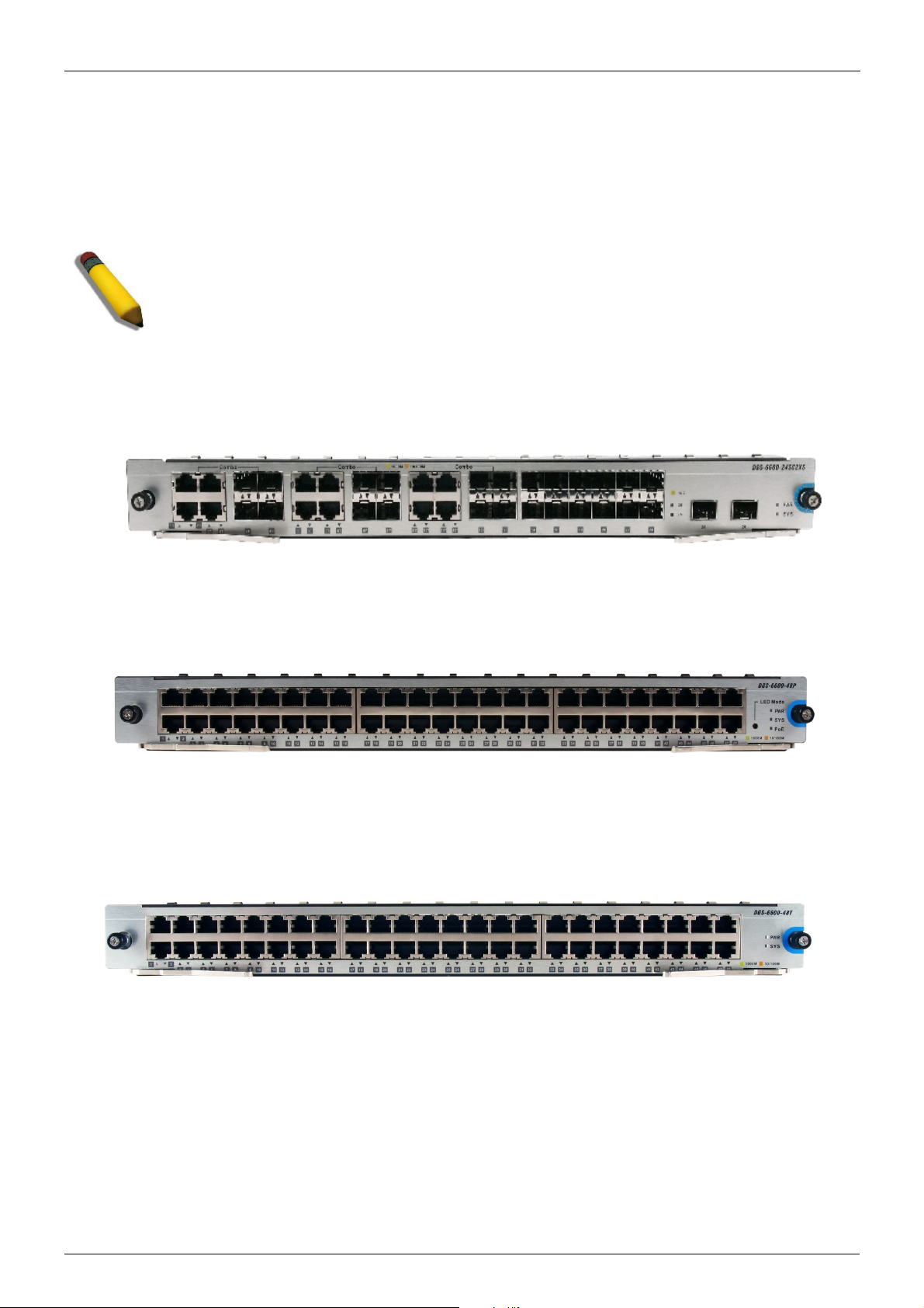
• DSG-6600-24SC2XS I/O Card
• DGS-6600-48P I/O Card
• DGS-6600-48T I/O Card
• DGS-6600-48S I/O Card
• DGS-6600-48TS I/O Card
• DGS-6600-8XG I/O Card
• Supported User Interfaces
An Introduction to the DGS-6600 Series Switch
The D-Link's DGS-6600 series switch is a modular, chassis-based Ethernet backbone switch. It is
designed to be adaptable and scalable, it’s intended to be used in a variety of different network
designs and to be upgradable as those network designs change and mature. Currently, the DGS6600 series chassis is available in a 4-slot chassis (DGS-6604) and 8-slot chassis (DGS-6608)
design.
The DGS-6600 switch provides a management platform, it has a backplane switch capacity of
either; 576Gbps for the DGS-6604 or 1152Gbps for the DGS-6608. The backplane switch capacities
are per Management Module. The DGS-6604 chassis has 4 slots. These slots are designed to hold,
one management module and three line card modules. The DGS-6608 chassis has 8 slots. These
slots are designed to hold two management modules and six line card modules.
All of the supported modules are capable of being hot-swapped, this allows the module
configuration to be changed while the power is on, with minimal disruption to the operating system.
The DGS-6600 chassis provides a built-in power shelf that is designed to support, depending upon
which chassis type is used (DGS-6604 or DGS-6608), up to four (DGS-6604) or eight (DGS-6608)
redundant power modules. Multiple redundant power modules are designed to enable continuous
operation in the event of a power module failure.
DGS-6600 Configuration Guide
18
Page 19
Chapter 1-DGS-6600 Series Switch Product Summary Chapter Overview
Components and Hardware
The D-Link's DGS-6600 series switch is a modular, chassis-based Ethernet backbone switch
designed for adaptability and scalability. Currently, the DGS-6600 series chassis is available in a 4slot chassis (DGS-6604) and an 8-slot chassis (DGS-6608).
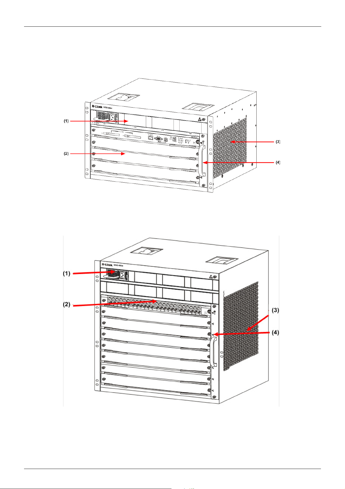
Figure 1-1 DGS-6604 Product Appearance
Figure 1-2 DGS-6608 Product Appearance
DGS-6600 Configuration Guide
19
Page 20

Chapter 1-DGS-6600 Series Switch Product Summary Chapter Overview
Chassis
The DGS-6604 uses a standard 19-inch chassis, which has a height of 280mm, a width of 484mm,
and a depth of 470mm. The chassis consists of the system module layer, fan layer, and power layer.
The layer that handles system modules consists of a module plug-in frame, which is used for
connecting the various DGS-6604 modules. The built-in power shelf is located at the top of the
chassis. The fan tray is located on the right-hand side of the chassis. The fan tray consists of eight
fans. The dimension of each fan is 80x80x20mm.
The DGS-6608 chassis consists of the system module layer, fan layer, and power layer. The layer
that handles system modules consists of a module plug-in frame, which is used for connecting the
various DGS-6608 modules. The built-in power shelf is located at the top of the chassis. The fan tray
is located on the right-hand side of the chassis. The fan tray consists of sixteen fans. The dimension
of each fan is 80x80x20mm.
Module Plug-in Frame
The module plug-in frame of the DGS-6604 consists of the module slots and the backplane. The
DGS-6604 supports four module slots. The slot at the top of the Switch can only be used for the
control management module. The other three slots can be used to connect to various line cards. All
the modules supported by the DGS-6604 are of the same height, width and depth. The dimensions
of each module are a height of 42mm, a width of 388mm, and a depth of 422mm. The modules of
the DGS-6604 are inserted into the Switch horizontally. The backplane of the DGS-6604 is used to
interconnect the control management card and the line cards that have been installed in the Switch.
When the slots of the DGS-6604 are fully populated, the modules of the DGS-6604 will have the
following layout:
• One control management module.
• Three line card modules to meet the network requirements.
The slot number used for the Control Management module is 1. Slots 2, 3, and 4 are used for line
card modules.
The module plug-in frame of the DGS-6608 consists of the module slots and the backplane. The
DGS-6608 supports eight module slots. The slots 4 and 5 of the Switch can only be used for the
control management module. The other six slots can be used to connect to various line cards. All
the modules supported by the DGS-6608 are of the same height, width and depth. The dimensions
of each module are a height of 42mm, a width of 388mm, and a depth of 422mm. The modules of
the DGS-6608 are inserted into the Switch horizontally. The backplane of the DGS-6608 is used to
interconnect the control management card and the line cards that have been installed in the Switch.
When the slots of the DGS-6608 are fully populated, the modules of the DGS-6608 will have the
following layout:
• Two control management module.
• Six line card modules to meet the network requirements.
The slot number used for the Control Management module is 4 and 5. Slots 1-3 to 6-8 are used for
line card modules.
DGS-6600 Configuration Guide
20
Page 21
Chapter 1-DGS-6600 Series Switch Product Summary Module List
Module List
The DGS-6604/6608 supports the modules described below:
Model Name Type Description Compatibility
DGS-6600-CM Control Module The Control Module is a CPU module for
the DGS-6604. The CPU module is used to
control the whole system. The DGS-6604
only supports 1 control module.
DGS-6600-CM-II Control Module The DGS-6600-CM-II is a CPU module for
the DGS-6604/6608. The DGS-6608 is able
to support 2 control modules.
DGS-660024SC2XS
DGS-6600-16XS I/O Module The DGS-6600-16XS has 16x 10G SFP
DGS-6600-48P I/O Module The DGS-6600-48P has 48x 10/100/1000
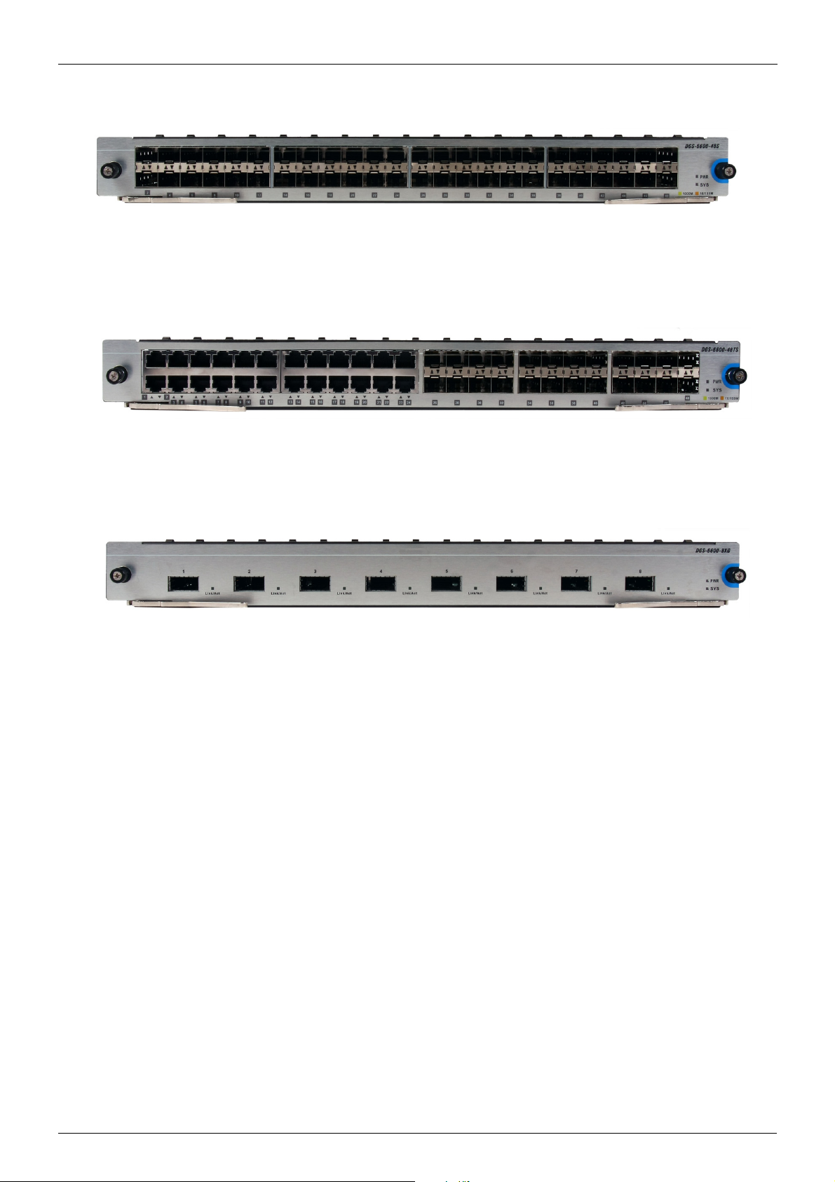
DGS-6600-48S I/O Module The DGS-6600-48S has 48x SFP
DGS-6600-48T I/O Module The DGS-6600-48T has 48x 10/100/1000
DGS-6600-48TS I/O Module The DGS-6600-48TS has 24x 10/100/1000
I/O Module The DGS-6600-24SC2XS has 12 SFP
ports, 12 combo ports (10/100/1000Base-T/
SFP Module) and 2 SFP+ ports.
ports +.
RJ-45 Ports and PoE.
interfaces.
RJ-45 ports.
Base-T and 24x SFP ports module
interfaces.
DGS-6604
DGS-6604/DGS-6608
DGS-6604
DGS-6604/DGS-6608
DGS-6604/DGS-6608
DGS-6604/DGS-6608
DGS-6604/DGS-6608
DGS-6604/DGS-6608
DGS-6600-8XG I/O Module This module has 8x 10G XFP module
interfaces.
Table 1-1 List of supported modules
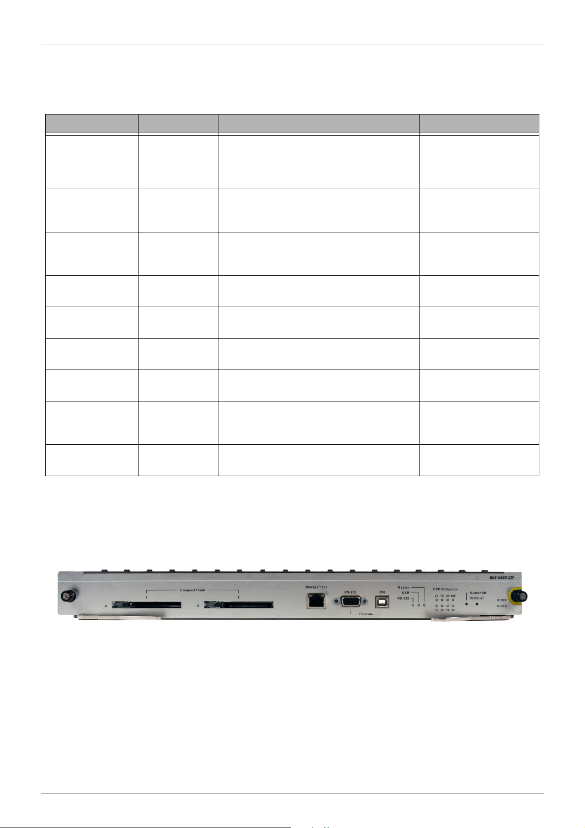
DGS-6600-CM
Figure 1-3 DGS-6600-CM
Compact Flash Slot
The DGS-6600-CM Control Module has two compact flash slots (CF1 and CF2). Install a card in the
compact flash slot 1 to store the system configuration, log, and runtime image files. Slot 2 is for
debugging purposes (please see “Debug Information to Compact Flash” on page 601)
DGS-6604
The LED indicator will flash green when data from the compact flash card is being accessed.
Management Port
DGS-6600 Configuration Guide
21
Page 22
Chapter 1-DGS-6600 Series Switch Product Summary Module List
NOTE: The terminal emulation application may need to be restarted if the USB
cable is disconnected and plugged it back into the host the Switch is being accessed
from.
The DGS-6600-CM Control Module is equipped with an auxiliary Gigabit Ethernet port for
out-of-band management. The IP address configured on the management port can be in the same
domain as the one assigned to the I/O module.
UART Console Interface
The DGS-6600-CM front panel provides two types of UART Console Interface, an RS-232
connector and a USB connector. These two interfaces are mutually exclusive, with the USB
interface having a higher priority. If the Switch is currently being managed via the RS-232 console
connection and a USB connection is established, the CLI engine will use the USB connection and
automatically disconnect the user who is connected to the Switch via the RS-232 console
connection.
The switching between the RS-232 and USB console connection is automatically controlled by the
firmware. However, this feature is disabled during system bootup. Therefore, it is strongly
recommended not to change the console connection interface during system bootup, as important
bootup information may be missed.
In order to use the USB console interface the host will need to have a terminal emulation application
(e.g., Hyper Terminal, Teraterm etc.) installed and the correct USB driver for the Switch.
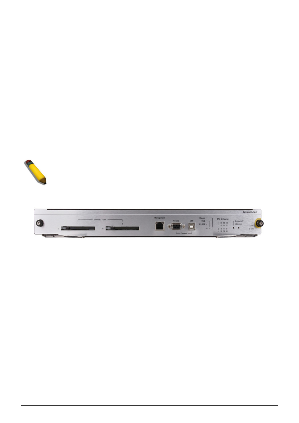
DGS-6600-CM-II
Compact Flash Slot
The DGS-6600-CM-II Control Module has two compact flash slots (CF1 and CF2). Install a card in
the compact flash slot 1 to store the system configuration, log, and runtime image files. Slot 2 is for
debugging purposes (please see “Debug Information to Compact Flash” on page 601)
The LED indicator will flash green when data from the compact flash card is being accessed.
Management Port
The DGS-6600-CM-II Control Module is equipped with an auxiliary Gigabit Ethernet port for
out-of-band management. The IP address configured on the management port can be in the same
domain as the one assigned to the I/O module.
Figure 1-4 DGS-6600-CM-II
UART Console Interface
The DGS-6600-CM-II front panel provides two types of UART Console Interface, an RS-232
connector and a USB connector. These two interfaces are mutually exclusive, with the USB
interface having a higher priority. If the Switch is currently being managed via the RS-232 console
connection and a USB connection is established, the CLI engine will use the USB connection and
automatically disconnect the user who is connected to the Switch via the RS-232 console
connection.
DGS-6600 Configuration Guide
22
Page 23
Chapter 1-DGS-6600 Series Switch Product Summary Module List
NOTE: The terminal emulation application may need to be restarted if the USB
cable is disconnected and plugged it back into the host the Switch is being accessed
from.
The switching between the RS-232 and USB console connection is automatically controlled by the
firmware. However, this feature is disabled during system bootup. Therefore, it is strongly
recommended not to change the console connection interface during system bootup, as important
bootup information may be missed.
In order to use the USB console interface the host will need to have a terminal emulation application
(e.g., Hyper Terminal, Teraterm etc.) installed and the correct USB driver for the Switch.
DSG-6600-24SC2XS I/O Card
DGS-6600-48P I/O Card
DGS-6600-48T I/O Card
Figure 1-5 DGS-6600-24SC2XS
Figure 1-6 DGS-6600-48P
Figure 1-7 DGS-6600-48T I/O Card
DGS-6600 Configuration Guide
23
Page 24
Chapter 1-DGS-6600 Series Switch Product Summary Supported User Interfaces
DGS-6600-48S I/O Card
Figure 1-8 DGS-6600-48S I/O Card
DGS-6600-48TS I/O Card
Figure 1-9 DGS-6600-48TS I/O Card
DGS-6600-8XG I/O Card
Figure 1-10 DGS-6600-8XG I/O Card
Supported User Interfaces
The Switch can be configured using the following methods:
• Command-Line Interface
• MIB Browser
DGS-6600 Configuration Guide
24
Page 25

Volume 1-Configuration Fundamentals / Chapter 2-Quick Start Chapter Overview
Chapter 2
Quick Start
Chapter Overview
The following topics are included in this chapter, please go to the topic for more detailed information:
• Chapter Overview
• An Introduction to Quickly Setting Up the DGS-6600 Series Switch
• Preparation for Installation
• Static Discharge Damage Prevention
• Moving the Device
• System Grounding Requirements
• Simple Grounding Steps
• Installation Site Requirements
• Ventilation Requirements
• Removing and Installing Modules from the DGS-6600 Series Switch
• Removing Modules from the DGS-6600
• Installing Modules in the DGS-6604 & DGS-6608
• Configuring the Connection To The Switch
• Connecting a Terminal to the Console Port
• SNMP-Based Management
An Introduction to Quickly Setting Up the DGS-6600 Series Switch
The following chapter discusses how to create user accounts on the Switch. User accounts can be
used to protect access to the command-line interface. The user can create several user accounts
with different access-levels.
Preparation for Installation
To ensure normal operation and to prolong the lifespan of the DGS-6600, the appropriate
temperature and humidity must be maintained in the equipment room (please see Table 2-1 on
page 25).
If the equipment room’s temperature and humidity do not meet the specified requirements the
equipment may sustain damage.
Operating Temperature Operating Humidity
0ºC-50ºC 10%-90% RH non-condensed
Table 2-1
DGS-6600 Configuration Guide
25
Page 26

Volume 1-Configuration Fundamentals / Chapter 2-Quick Start Preparation for Installation
Note:
The ambient temperature and humidity should be measured at a point that is 1.5m
above the floor and 0.4m in front of the equipment when there is no protective plate
in the front or back of the equipment rack.
Static Discharge Damage Prevention
To prevent damage from static electricity, please use the following guidelines:
• Be sure to install an adequate ground for all electronic equipment.
• Use appropriate dust prevention measures.
• Maintain the required humidity in the operating environment.
• Hold circuit boards by their edges. Do not touch any components on the printed circuit
board (PCB).
• Always wear an anti-static wrist strap when working near any electronic circuitry.
• Do not allow clothing to touch circuit boards. An antistatic wrist strap will only prevent
static electricity from the human body, it will not reduce the static electricity build up on
clothing.
Moving the Device
The DGS-6600 series Switch is quite heavy. When handling, please use the following guidelines:
• Avoid moving the equipment frequently.
• Seek assistance in lifting if the weight of the chassis is more then you can lift safely alone.
• Lift and move the chassis using the handles on the top panel (please see Table 2-1 on
page 27).
• Turn off all power supplies and unplug all power cables before moving the equipment.
• Completely loosen the thumb/Phillips screws and pull the card levers to remove each and
all line cards, fan tray, and power modules from the chassis before moving the chassis.
DGS-6600 Configuration Guide
26
Page 27
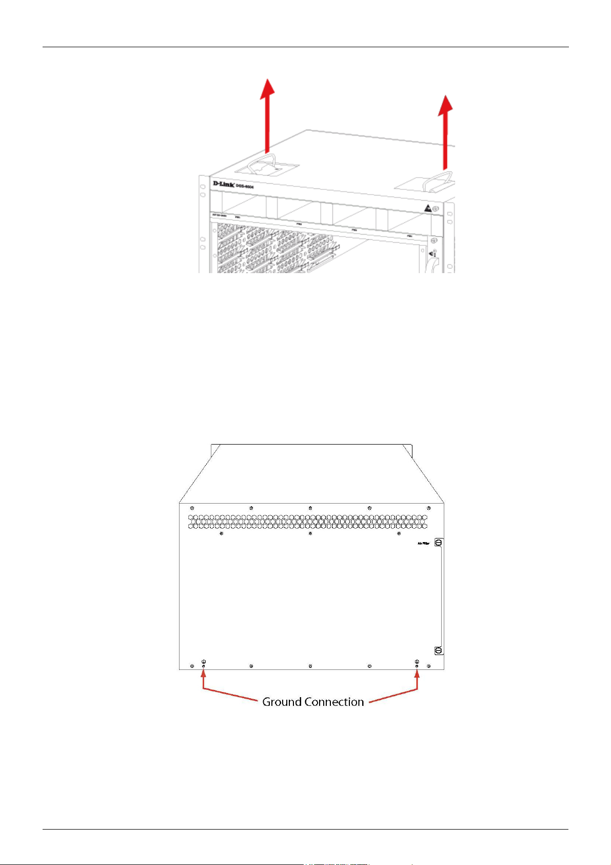
Volume 1-Configuration Fundamentals / Chapter 2-Quick Start Preparation for Installation
Figure 2-1
System Grounding Requirements
Proper grounding will help to ensure the stable and reliable operation of the DGS-6600 series
switch. Be sure to verify that the grounding conditions meet the grounding requirements and all
devices are grounded appropriately before using the DGS-6600 series switch.
Figure 2-2
DGS-6600 Configuration Guide
27
Page 28

Volume 1-Configuration Fundamentals / Chapter 2-Quick Start Installation Site Requirements
Simple Grounding Steps
• Unfasten the nut on the rear grounding post of the equipment.
• Affix the terminal of the grounding cable to the grounding pole.
• Fasten the nut back on the grounding post.
• Connect the other end of the grounding cable to a suitable grounding bar.
Installation Site Requirements
The DGS-6600 series switch must be used indoors. To ensure normal operation and to prolong the
lifespan of the equipment, the installation site must meet the following requirements:
Requirements for Rack Mounting:-
If you plan to mount the DGS-6600 in a frame, please use the following guidelines:
• Install the switch in an open cabinet if possible. If you install the switch inside a closed
cabinet please ensure that the cabinet has a good ventilation and heat dissipation system.
• Ensure that the cabinet is durable enough to bear the weight of the DGS-6600 and its
installed components.
• Ensure that the dimensions of the cabinet provide enough space for the installation of the
front, rear, left and right panels of the DGS-6600 for the purpose of heat dissipation.
• The frame should be properly grounded.
Ventilation Requirements
Table 2-3 on page 29 shows the ventilation requirements of the DGS-6600. You must allow sufficient
space near the vents to ensure proper ventilation.
After the cables have been connected, they should be arranged into bundles or placed on the
cabling rack to prevent the obstruction of air intakes and vents.
DGS-6600 Configuration Guide
28
Page 29
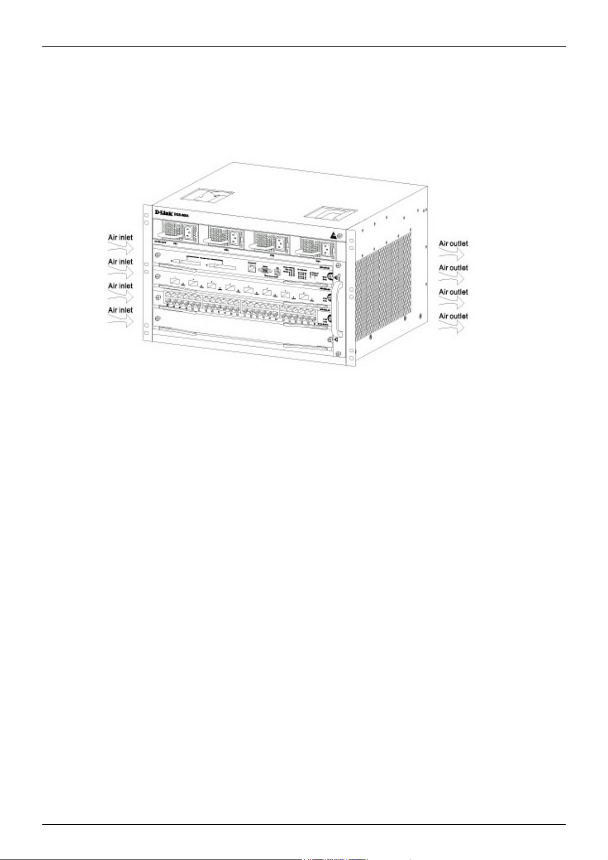
Volume 1-Configuration Fundamentals / Chapter 2-Quick Start Removing and Installing Modules from the DGS-6600 Series Switch
Figure 2-3
Removing and Installing Modules from the DGS-6600 Series Switch
Removing Modules from the DGS-6600
• Unplug all copper/fibre cabling, i.e. RJ45 twisted-pair and fibre optic cables from the module to be removed.
• Loosen and unscrew the panel’s two captive screws.
• Use both hands to pull the levers, on the left and right hand sides of the board, to remove
the module from the DGS-6600.
Installing Modules in the DGS-6604 & DGS-6608
• Remove the component card or blank panel as instructed in the section Removing Modules from the DGS-6600
• Insert the new module into the guide rail of the vacant slot.
• Use the levers on the left and right hand side to push the board into position and tighten
the two captive screws on the module using a straight screw driver.
DGS-6600 Configuration Guide
29
Page 30

Volume 1-Configuration Fundamentals / Chapter 2-Quick Start Configuring the Connection To The Switch
Configuring the Connection To The Switch
Connecting a Terminal to the Console Port
Connect the supplied RJ-45-to DB-9 adapter cable to the standard 9-pin serial port on the PC.
Connect the other end of the cable to the console port on the switch. Set the terminal emulation
software as follows:
Baud rate: 115200
Data bits: 8
Parity: None
Stop bits: 1
Flow control: None
Select VT100 for the terminal emulation mode
After you have correctly set up the terminal, plug the power cable into the power supply on the
switch. The boot sequence will appear in the terminal.
Press the Enter key at the password prompt. There is no default password for the Switch.
Enter the commands to complete your desired tasks. Many commands require administrator-level
access privileges. See the Command Line Interface (CLI) Reference Guide on the documentation
CD for a list of all commands and additional information using the CLI.
Telnet Management Users may also access the switch CLI by using the PC’s Command Prompt. To
access it from the PC, users must first ensure that a valid connection is made through the Ethernet
port of the Switch and the PC, then click Start > Programs > Accessories > Command Prompt on the
PC. Once the console window opens, enter the command telnet 10.90.90.90 (depending on
configured IP address) and press Enter on the keyboard. The user should be directed to the
opening console screen for the CLI of the switch, press the Enter key at the password prompts.
There is no default password for the Switch.
SNMP-Based Management
The Switch can be managed with D-Link D-View or any SNMP-compatible console program. The
SNMP function is disabled by default for D-Link managed switches.
DGS-6600 Configuration Guide
30
Page 31

Part 1- Configuration Fundamentals
The following chapters are included in this volume:
• Command-Line Interface (CLI)
• Accessing the Command Line Interface
• User Account Configuration
• Accessing the Web Interface (Web UI)
• Time Configuration
• DGS-6600 Default Metric
Page 32

Volume 1-Configuration Fundamentals / Chapter 3-Command-Line Interface (CLI) Command-Line Interface Overview
Chapter 3
Command-Line Interface (CLI)
Command-Line Interface Overview
The following topics are included in this chapter, please go to the topic for more detailed information:
• Command-Line Interface Overview
• An Introduction to the Command-Line Interface
• Command Mode and User Privilege Level
• User EXEC Mode Configuration Commands
• Help Features
• Editing Features
• Using Abbreviated Commands
• Error Messages
• Command Prompt
• Login Banner
• Establishing a Telnet Connection to a Remote Device
• Common Parameter Syntax Conventions
• Allowed Character Strings And String Examples
• Time and Date Configuration
An Introduction to the Command-Line Interface
The command-line interface (CLI) is a user interface that is available for inputting commands to
manage the Switch. Users can access the CLI using either the local console or a remote console.
This chapter describes the different features of the command-line interface that are available when
configuring the Switch.
Command Mode and User Privilege Level
There are several command modes available in the command-line interface (CLI). The set of
commands available, to the user, depends upon two factors, the mode the user is currently in and
their privilege level. For each case, the user can see all the commands that are available when in a
particular command mode by entering a question mark (?) at the system prompt.
The command-line interface has four privilege levels:
• Basic User- Privilege Level 1. This user account level has the lowest priority of the user
accounts and is allowed to use, system show commands in, the terminal control interface.
The purpose of this type of user account level is for basic system checking. This user
account can only show limited information that is not related to security. The most
important limitation of this account is that there is no way of changing the access right
level.
• Advanced User- Privilege Level 2. This user account level allowed to use the terminal
control interface to enter, some, privileged EXEC mode configurations.
DGS-6600 Configuration Guide
32
Page 33

Volume 1-Configuration Fundamentals / Chapter 3-Command-Line Interface (CLI) Command-Line Interface Overview
• Power User- Privilege Level 12. This user account level is used to grant system
configuration rights for users who need to change or monitor system configuration, except
for security related information such as user accounts and SNMP account settings, etc.
• Administrator- Privilege Level 15. This administrator user account level can monitor all
system information and change any of the system configuration settings expressed in this
configuration guide.
The command-line interface has three basic command modes:
• User EXEC mode
• Privileged EXEC mode
• Global Configuration mode
All other sub-configuration modes can be accessed via global configuration mode.
When a user logs in to the Switch, the privilege level of the user determines the command mode the
user will enter after their initial log in. The user will either log into user EXEC mode or privileged
EXEC mode. Users with a basic user and advanced user level will log into the Switch in user EXEC
mode. Users with power user and administrator level accounts will log into the Switch in privileged
EXEC mode. Therefore, user EXEC mode can operate at either basic user level or advanced user
level, and privileged EXEC mode can operate at either power user level or administrator level. The
user can only enter global configuration mode from privileged EXEC mode. Therefore, global
configuration mode can be accessed by users who have power user or administrator level user
accounts. As for sub-configuration modes, a subset of those can only be accessed by users who
have the highest secure administrator level privileges.
In user EXEC mode at advanced user level, the user is allowed to enter privileged EXEC mode by
entering the enable password. In privileged EXEC mode, the user is allowed to exit to the user
EXEC mode at advanced user level by entering the disable command. The enable password and
disable commands are functions that can be used to switch between user EXEC mode and
privileged EXEC mode.
DGS-6600 Configuration Guide
33
Page 34

Volume 1-Configuration Fundamentals / Chapter 3-Command-Line Interface (CLI) Command-Line Interface Overview
Figure 3-1 Command Mode State Diagram
NOTE: Not all configuration modes are listed in the above figure. For example, in global
configuration mode, enter “router ospf” to enter OSPF router configuration mode
Table 2-1 describes in brief the available command modes. Only the basic command modes and
some of the sub-configuration modes are enumerated. The basic command modes and basic
sub-configuration modes are further described in the following chapters. Descriptions for the rest of
the sub-configuration modes are not provided in this section. For more information on the additional
sub-configuration modes, the user should refer to the chapters relating to these functions.
DGS-6600 Configuration Guide
34
Page 35

Volume 1-Configuration Fundamentals / Chapter 3-Command-Line Interface (CLI) User EXEC Mode Configuration Commands
The available command modes and privilege levels are described below:
Command Mode & Privilege Level Purpose
User EXEC mode at Basic User level For checking basic system settings, allowing users to change
the local terminal session settings, and verifying basic network
connectivity. Checking security related settings is not allowed
at this command mode and privilege level.
User EXEC mode at Advanced User level This level has almost the same access rights as user EXEC
mode at basic user level, except that a user in this mode and
at this level can enter privileged EXEC mode by entering the
enable command.
Privileged EXEC mode at Power User level For changing both local and global terminal settings,
monitoring, and performing certain system administration
tasks. The system administration tasks that can be performed
at this level includes the clearing of system configuration
settings, except for any security related information, such as
user accounts, SNMP account settings etc.
Privileged EXEC mode at Administrator level This level is identical to privileged EXEC mode at power user
level, except that a user at the administrator level can monitor
and clear security related settings.
Global Configuration Mode at Power User level For applying global settings, except for security related
settings, on the entire Switch. In addition to applying global
settings on the entire Switch, the user can access other
sub-configuration modes from global configuration mode.
Global Configuration Mode at Administrator
level
Interface Configuration Mode at Power User
level
VLAN Interface Configuration Mode For applying VLAN interface related settings.
VLAN Configuration Mode For applying settings to a VLAN.
IP Access-List Configuration Mode For specifying filtering criteria for an IP access list.
Table 3-1 Command Modes and Privilege Levels
For applying global settings on the entire Switch. In addition to
applying global settings on the entire Switch, the user can
access other sub-configuration modes from global
configuration mode.
For applying interface related settings.
User EXEC Mode Configuration Commands
User EXEC Mode at Basic User Level
This command mode is mainly designed for checking basic system settings, allowing users to
change the local terminal session settings and carry out basic network connectivity verification. One
limitation of this command mode is that it cannot be used to display information related to security.
The most significant limitation of this command mode is that there is no way of changing the access
right level of the logged in user.
This command mode can be entered by logging in as a basic user.
User EXEC Mode at Advanced User Level
User EXEC mode at advanced user level has the same purpose as user EXEC mode at basic user
level, except that user EXEC mode at advanced user level is allowed to use the enable command to
enter privileged EXEC mode.
DGS-6600 Configuration Guide
35
Page 36

Volume 1-Configuration Fundamentals / Chapter 3-Command-Line Interface (CLI) User EXEC Mode Configuration Commands
This command mode can be entered by logging in as an advanced user or by using the disable
command in privileged EXEC mode.
In the following example, the user is currently logged in as an advanced user in privileged EXEC
mode and uses the disable command to return to user EXEC mode at advanced user level:
DGS-6600:15#disable
DGS-6600:2>
Privileged EXEC Mode at Power User Level
Users logged into the Switch in privileged EXEC mode at this level can change both local and global
terminal settings, monitor, and perform system administration tasks like clearing configuration
settings (except for security related information such as user accounts, SNMP account settings etc.)
There are two methods that a user can use to enter privileged EXEC mode at power user level. The
first method is to login to the Switch with a user account that has a privilege level of 12. The other
method is to use the enable privilege LEVEL command in user EXEC mode.
In the following example, the user enters privileged EXEC mode at power user level by logging in
with a user account called “power-user” that has a privilege level of 12:
User Access Verification
Username: power-user
Password:
DGS-6600 Chassis-based High-Speed Switch
Command Line Interface
Firmware: 2.10.011
Copyright (c) 2012 D-Link Corporation. All rights reserved.
DGS-6600:12#
In the following example, the user enters the enable privilege LEVEL command in user EXEC
mode to enter privileged EXEC mode at Power User level:
DGS-6600:2>enable privilege 12
DGS-6600:12#
Privileged EXEC Mode at Administrator Level
This command mode has a privilege level of 15. Users logged in with this command mode can
monitor all system information and change any system configuration settings mentioned in this
Configuration Guide.
There are two methods that a user can use to enter privileged EXEC mode at administrator level.
The first method is to login to the Switch with a user account that has a privilege level of 15. The
second method requires a user to login to the Switch in as a user with an advanced user or power
user level and use the enable privilege LEVEL command.
In this command mode, the user can return to user EXEC mode at an advanced user level by
entering the disable command.
DGS-6600 Configuration Guide
36
Page 37

Volume 1-Configuration Fundamentals / Chapter 3-Command-Line Interface (CLI) User EXEC Mode Configuration Commands
In the following example, the user is currently logged in as an administrator in privileged EXEC
mode and uses the disable command to return to user EXEC mode at an advanced user level:
DGS-6600:15#disable
DGS-6600:2>
In the following example, the user enters the enable privilege LEVEL command in privileged EXEC
mode at power user level to enter privileged EXEC mode at an administrator level:
DGS-6600:12#enable privilege 15
DGS-6600:15#
Global Configuration Mode
The primary purpose of global configuration mode is to apply global settings on the entire Switch.
Global configuration mode can be accessed at both power user and administrator level. However,
security related settings are not accessible at power user level. In addition to applying global
settings on the entire Switch, the user can also access other sub-configuration modes.
In order to access global configuration mode, the user must be logged in as an administrator or
power user and use the configure terminal command in privileged EXEC mode.
In the following example, the user is logged in as an Administrator in privileged EXEC mode and
uses the configure terminal command to access global configuration mode:
DGS-6600:15#configure terminal
DGS-6600:15(config)#
The exit command is used to exit global configuration mode and return to privileged EXEC mode.
The procedures to enter the different sub-configuration modes can be found in the related chapters
in this Configuration Guide. The command modes are used to configure the individual functions.
Interface Configuration Mode
Interface configuration mode is used to configure the parameters for an interface or a range of
interfaces. An interface can be a physical port, VLAN, or other virtual interface. Thus, interface
configuration mode is distinguished further according to the type of interface. The command prompt
for each type of interface is slightly different.
VLAN Interface Configuration Mode
VLAN interface configuration mode is one of the available interface modes and is used to configure
the parameters of a VLAN interface.
To access VLAN interface configuration mode, use the following command in global configuration
mode:
Command Explanation
DGS-6600:15(config)#interface vlanVLAN-ID Enters VLAN interface configuration mode.
DGS-6600 Configuration Guide
37
Page 38

Volume 1-Configuration Fundamentals / Chapter 3-Command-Line Interface (CLI) User EXEC Mode Configuration Commands
Using the End and Exit Commands
The end command can be used to return to privileged EXEC mode from any configuration task in
any configuration mode. If a user enters the end command while in user EXEC mode, the user will
be logged out of the session. The exit command is used to end the current mode and return to the
mode that the user was in previously. If the Switch is in global configuration mode, the exit
command will return the Switch to privileged EXEC mode.
Use the following commands to end the current configuration session or exit the current mode:
Command Explanation
end Ends the current configuration session.
exit Exits the current mode.
In the following example, the user uses the end command in interface mode to return to privileged
EXEC mode:
DGS-6600:15(config-if)#end
DGS-6600:15#
In the following example, the exit command is used in interface mode to return to global
configuration mode:
DGS-6600:15(config-if)#exit
DGS-6600:15(config)#
Help Features
The help feature allows the user to get instant and interactive guidance information on using the CLI
commands. The following list describes the different help features that are available on the Switch:
Command Purpose
ABBREVIATED-COMMAND-ENTRY? Obtains a list of commands that begin with a particular character
string. For example:
DGS-6600:15#di?
dir List directory contents
disable Turn off privileged mode command
DGS-6600:15#
ABBREVIATED-COMMAND-ENTRY <TAB> Completes a partial command name.
For example:
DGS-6600:15#show spa<TAB>
DGS-6600:15#show spanning-tree
Table 3-2 Help System
DGS-6600 Configuration Guide
38
Page 39

Volume 1-Configuration Fundamentals / Chapter 3-Command-Line Interface (CLI) User EXEC Mode Configuration Commands
Command Purpose
? Lists all the commands that are available in a particular command
mode. For example:
DGS-6600:2>?
Exec commands:
clear Reset function
copy Copy
crypto Generate encrypt key
dir List of directory contents
disable Turn off privileged mode command
enable Turn on privileged mode command
end Exit from the EXEC
COMMAND ? Lists the associated keywords for a command. For example:
DGS-6600:15#copy ?
WORD Specifies the URL
debug Debug information
running-config The running-config
startup-config The startup-config
system-log System-log file
DGS-6600:15#
COMMAND KEYWORD ? Lists the associated arguments for a keyword. For example:
DGS-6600:15(config)#spanning-tree mode ?
mstp Multiple Spanning Tree Protocol
rstp Rapid Spanning Tree Protocol
stp Spanning Tree Protocol(Compatible Mode)
DGS-6600:15(config)#
Table 3-2 Help System (continued)
DGS-6600 Configuration Guide
39
Page 40

Volume 1-Configuration Fundamentals / Chapter 3-Command-Line Interface (CLI) User EXEC Mode Configuration Commands
The following example, the user enters the abbreviated command entry conf and the <TAB> key to
automatically complete the configure command:
DGS-6600:15#conf<TAB>
Help Command
A user can enter the help command in any command mode to display a brief description of the help
system.
In the following example, the user has entered the help command in user EXEC mode:
DGS-6600:2>help
CLI provides advanced help feature. When you need help,
anytime at the command line please press ‘?’.
If nothing matches, the help list will be empty and you must backup
until entering a ‘?’ shows the available options.
Two styles of help are provided:
1. Full help is available when you are ready to enter a
command argument (e.g. ‘show ?’) and describes each possible
argument.
2. Partial help is provided when an abbreviated argument is entered
and you want to know what arguments match the input
(e.g. ‘show ve?’.)
DGS-6600:2>
Editing Features
The CLI user interface supports the following keystrokes for editing purposes:
Keystroke Purpose
<DELETE> Deletes character under the cursor and shifts remainder of the line to the left.
<BACKSPACE> Deletes character to the left of the cursor and shifts remainder of the line to the
left.
<LEFT ARROW> Moves cursor to the left.
<RIGHT ARROW> Moves cursor to the right.
<CTRL+R> Redisplays the current command line if the Switch suddenly sends messages to
the screen.
<RETURN> Scrolls down to display the next line.
<SPACE> Scrolls down to display the next page.
<ESC> Escapes from the page being displayed.
<TAB> Automatically completes a command.
Table 3-3 Editing Features
DGS-6600 Configuration Guide
40
Page 41

Volume 1-Configuration Fundamentals / Chapter 3-Command-Line Interface (CLI) User EXEC Mode Configuration Commands
Using Abbreviated Commands
The Switch supports abbreviated commands. In order to enter a command, a user only needs to
input enough characters for the Switch to uniquely recognize a command. For example if the user
types show span, the Switch will identify the command as show spanning-tree. However, if the
user does not type enough characters to uniquely identify the command an ambiguous command
error message will display. For example if the user types log the Switch cannot identify if the
command is login or logout.
To automatically complete a command with a short prefix, the user needs to press the <TAB> key
on their keyboard.
For example:
If the user types show span and presses the <TAB> key on their keyboard the command will
automatically complete to display show spanning-tree.
The No and Default Command Forms
Many of the configuration commands can be disabled or reset to their default values by using a no
prefix before the command. One function that supports the no command form is the password
encryption command. For example, to disable the password encryption function globally on the
Switch the user would need to enter the no password encryption command in global configuration
mode. In order to re-enable the password encryption function, the user would need to enter the
password encryption command in global configuration mode.
Example of Using the No Command Form
In the following example, the user has typed in the no password encryption command in global
configuration mode.
DGS-6600:15(config)#no password encryption
DGS-6600:15(config)#
Some commands also have a default option, which the user can use to return the parameters of a
command back to factory defaults. One command that supports the default option is the ip telnet
service-port command. For example, entering the default ip telnet service-port command in
global configuration mode will return the banner login message back to factory defaults.
Example of Using the Default Command Form
In the following example, the default ip telnet service-port command is entered in global
configuration mode to return the Telnet service port to default settings.
DGS-6600:15(config)#default ip telnet service-port
DGS-6600:15(config)#
DGS-6600 Configuration Guide
41
Page 42

Volume 1-Configuration Fundamentals / Chapter 3-Command-Line Interface (CLI) User EXEC Mode Configuration Commands
Error Messages
The following table explains the error messages that will appear if the user inputs a command
incorrectly in the CLI:
Error Message Meaning
Ambiguous command Not enough keywords were entered for the Switch to
recognize the command.
Incomplete command The command was not entered with all the required keywords.
Invalid input detected at ^ marker The command was entered incorrectly.
Argument is too long The length of the command is longer than 384 characters.
Users can only input an argument that is less than, or equal to
384 characters.
Table 3-4 Error Messages
Example of an Ambiguous Command Error
In the following example, the user has typed in the word log in privileged EXEC mode. However,
there are not enough letters to enable the Switch to identify if the command is login or logout.
DGS-6600:15#log
% Ambiguous command: “log”
DGS-6600:15#
Example of an Incomplete Command Error
In the following example, the user has typed in the ping command in privileged EXEC mode.
However, there are not enough keywords for the Switch to execute the command.
DGS-6600:15#ping
% Incomplete command.
DGS-6600:15#
Example of an Invalid Input Detected at ^ Marker Error
In the following example, the user has tried to enter the shutdown command in global configuration
mode. Since the shutdown command is not available in global configuration mode, the “Invalid
input detected at marker” error appears in the console window, indicating the location of the error.
DGS-6600:15(config)#shutdown
^
% Invalid input detected at ‘^’ marker.
DGS-6600:15(config)#
DGS-6600 Configuration Guide
42
Page 43

Volume 1-Configuration Fundamentals / Chapter 3-Command-Line Interface (CLI) User EXEC Mode Configuration Commands
Using Command History
The Switch CLI provides a history or record of commands that have been entered in the current
console session. This feature is particularly useful for recalling long or complex commands or
entries, including access lists. The Switch records 20 command lines in its history buffer. The
command history feature is enabled by default.
The commands in the history buffer can be displayed by using the show history command.
The following example uses the show history command to display the commands in the history
buffer:
DGS-6600:15#show history
1 enable
2 configure terminal
3 default ip telnet service-port
4 end
5 show history
DGS-6600:15#
Recalling Commands
To recall commands from the history buffer, use one of the following key combinations:I
Command Explanation
<CTRL-P> or the <UP ARROW> key. Recalls commands in the history buffer, beginning with the most
recent command. Repeat the key sequence to recall successively
older commands.
<CTRL-N> or the <DOWN ARROW> key. Returns to more recent commands in the history buffer after
recalling commands with the <CTRL-P> or the <UP ARROW>
key. Repeat the key sequence to recall the most recent
commands successively.
Table 3-5 Recalling Commands
Command Prompt
The user can change the command prompt of the Switch so that it displays the product name,
system name, or a user-defined string. The user can also specify if the command prompt displays
the level of the user that is currently logged into the Switch. By default the CLI Prompt displays the
product name and the user level.
A command prompt is shown in the following format: WWWW:XX(YY)Z
Letter Description
WWWW Represents the model name of the Switch, e.g. DGS-6600, the system name of the
Switch, or the user-defined string. This part of the command prompt is always
followed by a colon.
XX Represents the user access level, e.g. 1 indicates a Basic User, 2 indicates an
Advanced User, 12 indicates a Power User, and 15 indicates an Administrator.
Table 3-6 Command Prompts
DGS-6600 Configuration Guide
43
Page 44

Volume 1-Configuration Fundamentals / Chapter 3-Command-Line Interface (CLI) User EXEC Mode Configuration Commands
Letter Description
(YY) Represents the configuration mode that the user is in. The available modes are
Global Configuration mode, Interface Configuration mode, VLAN Configuration mode,
Router mode, etc.
Z Represents if the user is in user EXEC mode or privileged EXEC mode. The “>”
symbol indicates that the user is in user EXEC mode. The “#” symbol indicates that
the user is in privileged EXEC mode or a configuration mode.
Table 3-6 Command Prompts (continued)
The following table lists some examples of the command prompts that the user will see in different
command modes. In the following table the Switch has been configured to use the product name as
the command prompt and display the privilege level of the user:
Command Mode and Privilege Level Command Prompt
User EXEC mode at Basic User level DGS-6600:1>
User EXEC mode at Advanced User level DGS-6600:2>
Privileged EXEC mode at Power User level DGS-6600:12#
Privileged EXEC mode at Administrator level DGS-6600:15#
Global Configuration mode DGS-6600:15(config)#
Interface Configuration mode DGS-6600:15(config-if)#
VLAN Interface Configuration mode DGS-6600:15(config-if)#
Table 3-7 Command Prompts
If the user wants to change the CLI prompt to be the product name, system name, or a user-defined
string, and specify if the privilege level should be displayed or hidden, the following command
should be entered in global configuration mode:
Command Explanation
command prompt [level | no-level] [string
Configures the CLI prompt.
STRING | product-name | system-name]
In the following example, the user configures the command prompt to display the privilege level and
use the user-defined string ”Comms-Rm”:
DGS-6600:2>enable
DGS-6600:15#configure terminal
DGS-6600:15(config)#command prompt level string Comms-Rm
Comms-Rm:15(config)#end
Filtering the Output from the Show Command
The user can filter the output of the show command to match a given expression as well as any of
lines that are associated with the expression.
DGS-6600 Configuration Guide
44
Page 45

Volume 1-Configuration Fundamentals / Chapter 3-Command-Line Interface (CLI) User EXEC Mode Configuration Commands
show COMMAND | {begin | include | exclude} REGULAR-EXPRESSION
Syntax Description
COMMAND Represents any show command.
| The vertical bar (pipe symbol) indicates that an output processing specification
will follow.
begin Specifying the begin syntax causes the Switch to search the output from the first
instance of a specified string.
include Specifying the include syntax causes the Switch to filter the output so that only
lines with a particular regular expression are displayed.
exclude Specifying the exclude syntax causes the Switch to exclude any lines that
contain a particular regular expression.
REGULAR-EXPRESSION Represents any regular expression (text string) that is found in the output of the
show command.
In the following example, the user filters the output of the show logging-buffer command so that
only the entries for the first instances of eth4.43:
DGS-6600:2>enable
DGS-6600:15#show logging buffer | begin eth4.43
...skipping
7 2010-08-26 07:38:28 eth4.43 state change from FWD to BLK for MSTID 0
6 2010-08-26 07:38:27 Interface eth4.43 is down
5 2010-08-26 07:38:27 Interface vlan1 is down
4 2010-08-26 07:38:09 eth4.43 state change from LRN to FWD for MSTID 0
3 2010-08-26 07:38:09 eth4.43 state change from BLK to LRN for MSTID 0
2 2010-08-26 07:38:06 Interface eth4.43 is up
1 2010-08-26 07:38:06 Interface vlan1 is up
DGS-6600:15#
In the following example, the user filters the output of the show logging-buffer command so that
only lines containing the expression eth4.43 are displayed:
DGS-6600:2>enable
DGS-6600:15#show logging buffer | include eth4.43
7 2010-08-26 07:38:28 eth4.43 state change from FWD to BLK for MSTID 0
6 2010-08-26 07:38:27 Interface eth4.43 is down
4 2010-08-26 07:38:09 eth4.43 state change from LRN to FWD for MSTID 0
3 2010-08-26 07:38:09 eth4.43 state change from BLK to LRN for MSTID 0
2 2010-08-26 07:38:06 Interface eth4.43 is up
DGS-6600:15#
DGS-6600 Configuration Guide
45
Page 46

Volume 1-Configuration Fundamentals / Chapter 3-Command-Line Interface (CLI) User EXEC Mode Configuration Commands
In the following example, the user filters the output of the show logging-buffer command so that
lines containing the expression eth4.43 are filtered out:
DGS-6600:2>enable
DGS-6600:15#show logging buffer | exclude eth4.43
Total logs:9
Index Date Times Log Text
----------------------------------------------------------------------------9 2010-08-26 07:42:28 The running CFG was saved to the startup CFG by user
anonymous, IP 0.0.0.0, via console
8 2010-08-26 07:38:49 Successfully login to the system by user anonymous, I
P 10.73.87.1, via Telnet at privilege level 2
5 2010-08-26 07:38:27 Interface vlan1 is down
1 2010-08-26 07:38:06 Interface vlan1 is up
DGS-6600:15#
Login Banner
The user can create a login banner that will display after successfully logging into the Switch. This
feature is useful as it can be used as a method for informing users about any future events or useful
information that the administrator would like to announce to any users who are connected to the
Switch, such as an upgrade on the network.
By default, the login banner displays information about the Switch model and firmware version.
To configure a login banner, enter the following command in global configuration mode:
Command Explanation
banner login STRING Configure the login banner.
In the following example, the user configures a login banner that displays the following message:
“Essential Network Maintenance at 18:00 tonight!
Make sure you are logged off the network before 18:00.
For more information contact the System Administrator on extension: 6716.”
DGS-6600 Configuration Guide
46
Page 47

Volume 1-Configuration Fundamentals / Chapter 3-Command-Line Interface (CLI) User EXEC Mode Configuration Commands
DGS-6600:15#configure terminal
DGS-6600:15(config)#banner login Essential Network Maintenance at 18:00 tonight!/
nMake sure you are logged off the network before 18:00./nFor more information
contact the System Administrator on extension: 6716.
DGS-6600:15(config)#
The following example displays the login banner that will appear after logging into the Switch:
User Access Verification
Username: adv-user
Password:
Essential Network Maintenance at 18:00 tonight!
Make sure you are logged off the network before 18:00.
For more information contact the System Administrator on extension: 6716.
DGS-6600:2>
The following example uses the default command in global configuration mode to return the login
banner back to default settings:
DGS-6600:15(config)#default banner login
DGS-6600:15(config)#
Establishing a Telnet Connection to a Remote Device
The user can establish a connection to a remote device that supports the Telnet protocol:
Command Explanation
telnet {IP-ADDRESS | IPV6-ADDRESS}[TCPPORT]
In the following example, the user establishes a Telnet connection to a device that has an IP
address of 10.1.1.254:
DGS-6600:2>telnet 10.1.1.254
Connecting to 10.1.1.254 ...
Connected to 10.1.1.254.
Escape character is ‘Ctrl-_’.
Establishes a connection to a remote device that
supports the Telnet protocol.
Telnet connecting ...
User Access Verification
Username:
DGS-6600 Configuration Guide
47
Page 48

Volume 1-Configuration Fundamentals / Chapter 3-Command-Line Interface (CLI) User EXEC Mode Configuration Commands
Workstation
Ethernet
TelnetClien t
TelnetServer
In the following example, the user establishes a Telnet connection to a device that has an IPv6
address of 2001:e10:5c00:2::101:253, with the default port 23:
DGS-6600:2>telnet 2001:e10:5c00:2::101:2534
Connecting to 2001:e10:5c00:2::101:253 ...
Connected to 10.1.1.254.
Escape character is ’Ctrl-_’.
Telnet connecting ...
User Access Verification
Username:
Figure 2-2 Workstation to Telnet Server diagram.
Common Parameter Syntax Conventions
The following section describes the syntaxes used for commonly used command parameters.
Interface-ID
An interface can be a physical port, a VLAN, or a channel-group. For a physical port in an Ethernet
switch, an interface-ID appears in the following format:
ethx.y
• x—For a standalone switch, this number is always 1. This can also represent the unit
number (stackable system) or slot number (chassis system).
• y—The interface number on the switch. The port numbers always begin at 1, starting on
the left, when facing the front of the Switch, for example, eth1.1, eth1.2.
For a VLAN interface, the format is vlanVLAN-ID. e.g. vlan1.
For a channel group (link aggregated) interface, the format is port-channelGROUP-NUM, for
example: port-channel3
MAC Address
DGS-6600 Configuration Guide
The acceptable formats for a MAC Address are 00-01-80-40-30-20, 00:01:80:40:30:20,
000180403020, and 0001.8040.3020.
The MAC address will always be displayed in the following format: 00-01-80-40-30-20
48
Page 49

Volume 1-Configuration Fundamentals / Chapter 3-Command-Line Interface (CLI) User EXEC Mode Configuration Commands
IP Parameters
An IP address will always be in the format of A.B.C.D. The subnet mask can be represented in
mask bit form or as an integer indicating the number of mask bits, as shown below:
A.B.C.D xxx.xxx.xxx.xxx
A.B.C.D/N
For example – 10.9.18.2 255.0.0.0 is interchangeable with 10.9.18.2/8. Note that a space is
required between A.B.C.D and xxx.xxx.xxx.xxx. A back slash ‘/’ has to be inserted between
A.B.C.D and N.
Allowed Character Strings And String Examples
Allowed Characters for File Name
A-Z
a-z
0-9
!#$%&'( )+,-.=@[ ]^_` { } ~
space
Allowed Characters for General Strings that Allow Spaces
A-Z
a-z
0-9
!#$%&'( )+,-.=@[ ] ^_` { } ~ / \ : * <
space
Allowed Characters for General Strings that Do Not Allow Spaces
A-Z
a-z
0-9
!#$%&'( )+,-.=@[ ]^_`{ } ~ / \ : * <
Encrypted Password
An encrypted password should start with *@&.
The allowed characters for an encrypted password are:
A-Z
a-z
0-9
+/
DGS-6600 Configuration Guide
49
Page 50

Volume 1-Configuration Fundamentals / Chapter 3-Command-Line Interface (CLI) User EXEC Mode Configuration Commands
Time and Date Configuration
The following section defines the display format the Switch uses to represent durations, calendar
date, and time respectively.
Durations
Durations are used to define the amount of intervening time in a time interval.
The Switch uses the following format to represent time, [v]DT[v]H[v]M[v]S. In this representation, the
value for each of the date and time elements replaces the date and time elements that follow the [v].
Leading zeros for each of the date and time elements are not required. Each date and time element
use a capital letter as a designator that is not replaced.
The following table explains the designators used for each date and time element:
Designator Description
D Used as the Day designator. This designator follows the
value for the number of days.
For example, a duration lasting "six days, seven hours, fifteen minutes, and nine seconds would be
represented as as follows, "6DT7H15M9S". If the value of a date and time element, including their
designator, is zero, the value may be omitted. Lower values can also be omitted for reduced
precision. For example, the following format, "13DT21H" is an acceptable form to represent 13 days
and 21 hours.
Calendar Dates
The Switch uses the following format to represent calendar dates, YYYY-MM-DD.
The following table explains the components that the Switch uses to represent calendar dates:
T Used as the Time designator. This designator precedes
the time components.
H Used as the Hour designator. This designator follows the
value for the number of hours.
M Used as the Minute designator. This designator follows the
value for the number of minutes.
S Used as the Second designator. This designator follows
the value for the number of seconds.
Table 3-8 Date and Time Element Designators
Date Component Description
YYYY Used to indicate a four-digit year, 0000 through to 9999.
MM Used to indicate a two-digit month of the year, 01
through to 12.
Table 3-9
DGS-6600 Configuration Guide
50
Page 51

Volume 1-Configuration Fundamentals / Chapter 3-Command-Line Interface (CLI) User EXEC Mode Configuration Commands
Date Component Description
DD Used to indicate a two-digit day of that month, 01
through to 31.
Table 3-9
For example, the Switch would represent the date “22nd of February 2012" as "2012-02-22."
This Switch allows calendar dates to be written with reduced precision. For example, if the user
inputs "2012-02" the Switch will identify the calendar date as "2012 February". If the user inputs
"2012" the Switch will identify the year as “2012”.
The format of YYYY-MM-DD is necessary for complete calendar date representations.
Time
The Switch uses the 24-hour clock system, with the following format: [hh]:[mm]:[ss].
The following table explains the components that the Switch uses to represent the time:
Date Component Description
For example "14:50:30".
Midnight is a special case and can be referred to as either "00:00" or "24:00". The notation "00:00" is
used at the beginning of a calendar day and is used more frequently. The notation usually used at
the end of a day is "24:00".
Countdown Timer
The Switch uses most its timers for protocol synchronization. The Switch timers usually use seconds
or milliseconds time units. The Switch usually abbreviates seconds to sec and milliseconds to msec
for unified display formatting.
[hh] Used to refer to a zero-padded hour between 00 and 24,
where 24 is only used to notate midnight at the end of a
calendar day.
[mm] Used to refer to a minute between 00 and 59
[ss] Used to refer to a second between 00 and 59.
Table 3-10 Switch Time Components
DGS-6600 Configuration Guide
51
Page 52

Volume 1-Configuration Fundamentals / Chapter 4-Accessing the Command Line Interface Chapter Overview
Chapter 4
Accessing the Command Line Interface
Chapter Overview
The following topics are included in this chapter, please go to the topic for more detailed information:
• Chapter Overview
• An Introduction to Accessing the Switch Using a Console Connection
• Accessing the Switch Using a Telnet Connection
• Enabling the Telnet Service
• Configuring the Telnet Service Port
• Specifying Telnet Terminals
• Displaying Trusted Host Telnet Terminals
• Closing an Active Terminal Session
• Terminal Settings
• Configuring the Number of Lines Displayed on Terminal Screen
• Configuring the Max Number of Characters Displayed per Terminal Line
• Configuring the Terminal Timeout
• List of Constants and Default Settings
An Introduction to Accessing the Switch Using a Console Connection
Initial configuration of the Switch needs to be carried out using one of the UART console interfaces
available on the DGS-6600-CM front panel. The DGS-6600-CM front panel provides two types of
UART console interface, an RS-232 connector and a USB connector.
In order to use the RS-232 or USB console interface the host will need to have a terminal emulation
application (e.g., Hyper Terminal, Teraterm etc.) installed. If using the USB console interface, the
correct USB driver for the Switch will also need to be installed on the connected host.
If using the RS-232 console connection, the host will need to have the following equipment:
• A terminal or a computer with an RS-232 serial port and the ability to emulate a terminal.
• A null modem or straight-through RS-232 cable with a female DB-9 connector for the console port on the Switch.
Carry out the following to connect a terminal to the RS-232 console port:
1) Connect the female connector of the RS-232 cable directly to the console port on the Switch,
and tighten the captive retaining screws.
2) Connect the other end of the cable to a terminal or to the serial connector of a computer
running terminal emulation software. Set the terminal emulation software as follows:
3) Select the appropriate serial port (COM port 1, COM port 2, etc).
4) Set the baud rate to 115200 bps.
5) Set the data format to 8 data bits, 1 stop bit, and no parity.
DGS-6600 Configuration Guide
52
Page 53

Volume 1-Configuration Fundamentals / Chapter 4-Accessing the Command Line Interface Chapter Overview
6) Set flow control to hardware.
7) Under Properties, select VT100 for Emulation mode.
8) After correctly setting up the terminal, plug the power cable into the power receptacle on the
back of the Switch. The boot sequence appears in the terminal.
9) After the boot sequence completes, the console login screen displays.
10) Ensure that any terminal or PC being used to make a console connection is configured to
match these settings.
11) If using the USB console connection, the host will need to have the following equipment:
• A terminal or a computer with USB port and the ability to emulate a terminal.
• A Type A to Type B USB cable.
Carry out the following to connect a terminal to the USB console port:
1) Connect the Type A connector end of the USB cable to an available USB port on the Switch.
2) Connect the Type B connector end of the USB cable to an available USB port on the computer
running the terminal emulation software. Set the terminal emulation software using the same
procedure described above.
NOTE: If both the RS-232 and USB connection are active on the device, the USB connection will have priority over the RS-232 connection. If the device is currently being managed
via the RS-232 console connection and a USB connection is established, the system will
disconnect the RS-232 connection and switch over to the USB connection.
If connecting to the Switch for the first time, press the <RETURN> key to start the login process.
In the following example, the user has started a console connection and enters privileged EXEC
mode:
DGS-6600 Chassis-based High-Speed Switch
Command Line Interface
Firmware: 3.00.080
Copyright (c) 2012 D-Link Corporation. All rights reserved.
DGS-6600:2>enable
DGS-6600:15#
DGS-6600 Configuration Guide
53
Page 54

Volume 1-Configuration Fundamentals / Chapter 4-Accessing the Command Line Interface Accessing the Switch Using a Telnet Connection
If the user has created a user name and password, the Switch will prompt the user to enter a user
name and password before accessing a command mode. The command mode the user initially
enters will depend on the privilege level assigned to the user name.
In the following example the user is prompted to enter a user name and password. The user enters
a user name with administrator level privileges and directly enters privileged EXEC mode:
User Access Verification
Username:Admin-User
Password:
DGS-6600 Chassis-based High-Speed Switch
Command Line Interface
Firmware: 3.00.080
Copyright (c) 2012 D-Link Corporation. All rights reserved.
DGS-6600:2>enable
DGS-6600:15#
NOTE: The user has three attempts to enter the correct password, before the login attempt
is refused.
Accessing the Switch Using a Telnet Connection
The Switch can be managed using a Telnet connection. Up to eight simultaneous Telnet sessions
can be made from the Switch.
NOTE: In order to successfully connect to the Switch using Telnet, an IP address needs to
be configured on the Switch
To start a Telnet connection on the Switch open a terminal emulation application on the PC and
enter the Telnet command followed by the IP address of the Switch.
In the following example, a Telnet connection is established to a Switch with an IP address of
10.73.87.99:
C:\>telnet 10.73.87.99
Telnet connecting ...
DDGS-6600 Chassis-based High-Speed Switch
Command Line Interface
Firmware: 3.00.080
Copyright (c) 2012 D-Link Corporation. All rights reserved.
DGS-6600:2>enable
DGS-6600:15#
DGS-6600 Configuration Guide
54
Page 55

Volume 1-Configuration Fundamentals / Chapter 4-Accessing the Command Line Interface Accessing the Switch Using a Telnet Connection
Enabling the Telnet Service
To re-enable the Telnet service after it has been disabled by the user, enter the following commands
in privileged EXEC mode:
Command Explanation
configure terminal Enters global configuration mode.
ip telnet server Enables the Telnet service.
Configuring the Telnet Service Port
The user can change the port used by the Telnet service by using the following command in global
configuration mode:
Command Explanation
ip telnet service-port TCP-PORT Configures the port used by the Telnet service.
To return the Telnet service on the Switch to the default setting use the default form of the
command.
In the following example, the user configures the TCP port number for Telnet to be 3000:
DGS-6600:15#configure terminal
DGS-6600:15(config)#ip telnet service-port 3000
DGS-6600:15(config)#end
Specifying Telnet Terminals
The user can specify the hosts that are allowed to manage the Switch using a Telnet connection by
using the following command in global configuration mode:
Command Explanation
ip trusted-host {IP-ADDRESS | NETWORKADDRESS/PREFIX-LENGTH} telnet
Specifies a host that is allowed to manage the
Switch using a Telnet connection.
In the following example, a trusted host with IP address 10.73.87.3 is allowed to manage the switch
using a Telnet connection:
DGS-6600:15#configure terminal
DGS-6600:15(config)#ip trusted-host 10.73.87.3 telnet
DGS-6600:15(config)#end
DGS-6600 Configuration Guide
55
Page 56

Volume 1-Configuration Fundamentals / Chapter 4-Accessing the Command Line Interface Terminal Settings
Displaying Trusted Host Telnet Terminals
The user can display a list of the hosts that are allowed to manage the Switch using a Telnet
connection by entering the following command in privileged EXEC mode:
Command Explanation
show ip trusted-host telnet Displays a list of the hosts that are allowed to
manage the Switch using a Telnet connection.
In the following example, the user displays a list of the hosts that are allowed to managed the Switch
using a Telnet connection:
DGS-6600:15#show ip trusted-host telnet
Index IP/Network Address Valid to Access
=====================================================
01 10.78.62.1/32 TELNET
02 10.73.87.1/32 TELNET
Total Entries: 2
DGS-6600:15#
Closing an Active Terminal Session
An active session can be ended using either the logout, exit, or end commands.
Command Explanation
logout Ends an active session.
exit If the exit command is entered in EXEC mode, the
active session will end.
end If the end command is entered in EXEC mode,
the active session will end.
Terminal Settings
Configuring the Number of Lines Displayed on Terminal Screen
The number of lines that are displayed can be changed by the user to meet their needs. The valid
entries for the number of lines that can be displayed is between 0 and 512. If the user specifies a
terminal length of 0, the display will continue to scroll down until the end of the display is reached. If
a terminal length is specified to a value other than 0, for example 50, then the display will stop after
50 lines. Output from a single command that overflows a single display screen is followed by the -More-- prompt. At the --More-- prompt the user can use the Ctrl-C, q, or Q keys to interrupt the
output and return to the prompt, press the <SPACEBAR> to display an additional screen of output,
or press the <RETURN> key to display one more line of output.
DGS-6600 Configuration Guide
56
Page 57

Volume 1-Configuration Fundamentals / Chapter 4-Accessing the Command Line Interface Terminal Settings
The user can use one of the following commands to change the default number of lines displayed on
the terminal screen for the current session or apply the changes to all future sessions:
Command Explanation
terminal length LINES Configures the number of lines that will be displayed on
the terminal screen for the current session.
OR
terminal length LINES default Configures the number of lines that will be displayed on
the terminal screen for all current and future sessions.
The following example configures the current session to display 60 lines on the terminal screen:
terminal length 60
The following example configures the current and all future sessions to display 60 lines on the
terminal screen:
terminal length 60 default
NOTE: The settings specified in these commands also apply to both Telnet and SSH sessions automatically.
Configuring the Max Number of Characters Displayed per Terminal Line
The user can specify the maximum number of characters that will displayed on each line in the
console window. The user can specify a value between 80 and 255 characters.
Use the following command to specify the number of characters that will be displayed on a terminal
line:
Command Explanation
terminal width <80-255> [default] Configures the maximum number of characters that can
be displayed in the terminal window. The range is from
80 to 255 characters and the argument default
specifies to save the setting permanently in the startup
configuration file.
In the following example, the user specifies that a maximum of 100 character can be displayed in a
terminal window and by using the default keyword saves the setting into the system configuration
file for the next switch startup.:
DGS-6600:2>terminal width 100 default
DGS-6600 Configuration Guide
57
Page 58

Volume 1-Configuration Fundamentals / Chapter 4-Accessing the Command Line Interface List of Constants and Default Settings
NOTE: The settings specified in these commands also apply to both Telnet and SSH sessions automatically.
Configuring the Terminal Timeout
The Switch uses a timer to specify the amount of time a terminal session should be idle before
timing out. The Switch uses the same timer for all terminal sessions, regardless of whether the
session was established by a direct serial connection, a Telnet connection, or an SSH connection.
To configure the amount of time the terminal session should be idle before timing out, enter the
following command in privileged EXEC mode:
Command Explanation
terminal timeout {never | 2_minutes |
5_minutes | 10_minutes| 15_minutes}
In the following example, the user configures an idle terminal session to time out after two minutes:
DGS-6600:2>enable
DGS-6600:15#terminal timeout 2_minutes
List of Constants and Default Settings
Constant Name Value
Maximum Telnet sessions 8
Local Console Baud Rate 115200 bps
Table 4-1 Constants Values
Variable Name Default Value
Configures the amount of time the terminal
session should be idle before timing out.
Telnet Service Enabled
Telnet Service Port TCP 23
Terminal Length 24 lines
Terminal Timeout Never
Table 4-2 Default Variable Values
DGS-6600 Configuration Guide
58
Page 59

Volume 1-Configuration Fundamentals / Chapter 5-User Account Configuration Chapter Overview
Chapter 5
User Account Configuration
Chapter Overview
The following topics are included in this chapter, please go to the topic for more detailed information:
• Chapter Overview
• An Introduction to Configuring User Accounts
• Creating User Accounts with Different Privilege Levels
• Creating User Accounts
• Displaying the User Accounts Setup on the Switch
• Displaying Active User Sessions on the Switch
• Creating and Configuring Enabled Passwords
• Creating an Enabling Password
• Displaying Enabled Passwords
• Logging into the Switch with a Different User Account
• Encrypting Passwords
• List of Constants and Default Settings
An Introduction to Configuring User Accounts
The following chapter discusses how to create user accounts on the Switch. User accounts can be
used to protect access to the command-line interface. The user can create several user accounts
with different access-levels.
Creating User Accounts with Different Privilege Levels
Creating User Accounts
The Switch supports user accounts with different access levels. The following access levels can be
assigned to user accounts, Level 1, Level 2, Level 12, & Level 15. If another level is specified, an
error message will be displayed on the console.
When a user logs in with a Level 1 or Level 2 account, the user will access the Switch in user EXEC
mode. In order to access higher privilege levels, a user needs to use the enable command.
However, if a user logs onto the Switch using a Level 1 user account, they will not be allowed to
enter privileged EXEC mode.
When a user logs in with a user account that has a privilege level of 12 or 15, the user will directly
enter privileged EXEC mode.
DGS-6600 Configuration Guide
59
Page 60

Volume 1-Configuration Fundamentals / Chapter 5-User Account Configuration Creating User Accounts with Different Privilege Levels
When creating a user account, the user can specify if the password will be entered in encrypted or
plain text form. If a password is entered into the Switch in plain-text form, but the password
encryption function is enabled, the password will be converted to encrypted form.
NOTICE: Make sure that the password is changed correctly before saving the changes to
the startup configuration
To create a new user account, use the following command in global configuration mode:
Command Explanation
username NAME [privilege LEVEL] password
{plain-text | encrypted} PASSWORD
The following example creates a user account called “admin” and a password of “mypassword”:
DGS-6600:2>enable
DGS-6600:15#configure terminal
DGS-6600:15(config)#username admin password plain-text mypassword
DGS-6600:15(config)#end
To remove a user account with the user name “admin”:
DGS-6600:2>enable
DGS-6600:15#configure terminal
DGS-6600:15(config)#no username admin
DGS-6600:15(config)#end
Creates a new user account.
Displaying the User Accounts Setup on the Switch
To display the user accounts setup on the Switch, use the following command in privileged EXEC
mode:
Command Explanation
show username [NAME] Displays the user accounts setup on the Switch.
The following example displays all the user accounts that have been setup on the Switch:
DGS-6600:15#show username
Password Encryption : Disabled
Username Access Level Password Encrypted
---------------------------------------------------------------------------------dlink 15 *@&fEqNCco3Yq9h5ZUglD3CZJT4LBvRndtZ *
admin 15 mypassword
Total Entries: 2
DGS-6600:15#
DGS-6600 Configuration Guide
60
Page 61

Volume 1-Configuration Fundamentals / Chapter 5-User Account Configuration Creating and Configuring Enabled Passwords
The table below describes the significant fields shown in the display:
Field Description
Encrypted ‘*’ denotes the entry’s password is encrypted. Empty indicates
that the password is ‘Plain Text’.
Table 5-1 Significant fields shown in the show username command output
The factory default settings have no user accounts setup. When the user account database is
empty, a user accessing the Switch using the console connection will directly enter user EXEC
mode at Power User level. The user can enter privileged EXEC mode, by entering an up-to-date
enable password. If a user attempts to make a Telnet connection when the user account database
is empty, the Switch will directly enter user EXEC mode.
Displaying Active User Sessions on the Switch
To display the user sessions that are currently running on the Switch, use the following command in
user EXEC mode:
Command Explanation
show user-session [console | telnet | ssh |
http | https]
The following example displays all the user accounts that have been setup on the Switch:
DGS-6600:2>show user-session
UI Codes: co - console, h - http, hs - https, s - ssh, te - telnet
ID Login Time From UI Level Username
------------------------------------------------------------------------------- 0 11:52:38, 2012-05-24 0.0.0.0 co 15 admin
* 5 11:52:52, 2012-05-24 10.70.89.1 te 2 dlink
Total Entries: 2
DGS-6600:2>
Displays the user accounts setup on the Switch.
Creating and Configuring Enabled Passwords
Creating an Enabling Password
The enable password command is used to create a password for entering privileged EXEC mode.
Different parameters can be specified when creating an enable password, including the privilege
level that the user will have after entering the password and whether the password will appear in
plain-text or encrypted form in the running configuration.
DGS-6600 Configuration Guide
61
Page 62

Volume 1-Configuration Fundamentals / Chapter 5-User Account Configuration Creating and Configuring Enabled Passwords
To create a new enable password use the following command in global configuration mode:
Command Explanation
enable password privilege LEVEL password
{plain-text | encrypted} PASSWORD
In the following example, the user creates a plain-text password using the word
“MyEnablePassword” with a privilege level of 15:
DGS-6600:2>enable
DGS-6600:15#configure terminal
DGS-6600:15(config)#enable password privilege 15 password plain-text
MyEnablePassword
DGS-6600:15(config)#end
Creates a new enable password.
Displaying Enabled Passwords
To display the enable passwords setup on the Switch, use the following command in privileged
EXEC mode:
Command Explanation
show enable password [privilege LEVEL] Displays the enable passwords that have been
setup on the Switch.
In the following example, the user displays all the enable passwords that have been setup on the
Switch:
DGS-6600:15#show enable password
Password Encryption :Disabled
Access Level Password
-----------------------------------------------------------------12 *@&fEqNCco3Yq9h5ZUglD3CZJT4LBvRndtZ(Encrypted)
15 MyEnablePassword(Plain Text)
Total Entries: 2
Logging into the Switch with a Different User Account
Enter the following command to log into the Switch with a different user name:
Command Explanation
login Allows the user to login with a different user name.
DGS-6600 Configuration Guide
62
Page 63

Volume 1-Configuration Fundamentals / Chapter 5-User Account Configuration Creating and Configuring Enabled Passwords
In the following example, the user logs into the switch with the user name “user1”:
DGS-6600:2>login
User Access Verification
Username: user1
Password:
DGS-6600 Chassis-based High-Speed Switch
Command Line Interface
Firmware: 3.00.080
Copyright (c) 2012 D-Link Corporation. All rights reserved.
DGS-6600:2>
Encrypting Passwords
By default, passwords defined by the username and enable commands are stored in plain-text
form in the configuration file, unless the specified password is in encrypted form when the user
account is setup. In order to increase security, the password encryption command can be used to
encrypt plain-text form passwords.
To encrypt all the passwords defined by the username commands, use the following command in
global configuration mode:
Command Explanation
password encryption Encrypts the passwords defined by the username
command.
NOTICE: The no password encryption command can be used to disable the encryption of
passwords in the configuration file. However, passwords that were created in encrypted
form or passwords that were converted to encrypted form by the last password encryption
command will remain in encrypted form and cannot be reverted back to plain text form.
The following example encrypts the passwords of user accounts and the authentication password:
DGS-6600:15#configure terminal
DGS-6600:15(config)#password encryption
DGS-6600:15(config)#end
NOTE: Even if the no password encryption command has been entered on the Switch,
the password of a user account can still be encrypted by specifying the encrypted option
with the username command.
DGS-6600 Configuration Guide
63
Page 64

Volume 1-Configuration Fundamentals / Chapter 5-User Account Configuration List of Constants and Default Settings
The following example shows the output of the show username command after the password
encryption command has been entered on the Switch:
DGS-6600:15#show username
Password Encryption : Enabled
Username Access Level Password Encrypted
--------------------------------------------------------------------------------admin 15 *@&Fxy+fgwFJI09+SpIYvXjcCuMdA7vnWTR/B *
dlink 15 *@&EukpPsazDH+ooJJq9CgH6SnBaE+gJj/Eww *
Kindo 15 *@&NUQjQWpaucJPOFFIgEr8kbKRItrrrrd/wN *
Total Entries: 3
DGS-6600:15#
List of Constants and Default Settings
Constant Name Value
Maximum Number of User
Accounts
Table 5-2 Constants Values
Variable Name Default Value
Number of User Accounts Setup on
the Switch
Enable Password None
Password Encryption Disabled
Table 5-3 Default Variable Values
4
None
DGS-6600 Configuration Guide
64
Page 65

Volume 1-Configuration Fundamentals / Chapter 6-Accessing the Web Interface (Web UI) Chapter Overview
Chapter 6
Accessing the Web Interface (Web UI)
Chapter Overview
The following topics are included in this chapter, please go to the topic for more detailed information:
• Chapter Overview
• An Introduction to Accessing the Switch using the Web Interface
• Configuration Commands
• Enabling the Web Interface
• Configuring the Web Service Port
• Specifying Web Management Terminals
• Displaying Trusted Host Web Terminals
• List of Constants and Default Settings
An Introduction to Accessing the Switch using the Web Interface
The Switch can be managed using the Web interface. Only one user can manage the Switch using
the Web at any one time.
NOTE: In order to successfully connect to the Switch using the Web interface, an IP address
needs to be configured on the Switch
To start a Web connection on the Switch, enter the IP address that has been defined for the device.
The URL in the address bar should read something like http://123.123.123.123, where the numbers
123 represent the IP address of the Switch.
Configuration Commands
Enabling the Web Interface
To re-enable the Web interface after it has been disabled by the user, enter the following commands
in privileged EXEC mode:
Command Explanation
configure terminal Enters global configuration mode.
ip http server Enables the Web interface.
end Exits global configuration mode.
DGS-6600 Configuration Guide
65
Page 66

Volume 1-Configuration Fundamentals / Chapter 6-Accessing the Web Interface (Web UI) Configuration Commands
In the following example, the user configures to enable the Web interface.
DGS-6600:15#configure terminal
DGS-6600:15(config)#ip http server
DGS-6600:15(config)#end
Configuring the Web Service Port
The user can change the port used by the Web service by using the following command in global
configuration mode:
Command Explanation
ip http service-port TCP-PORT Configures the port used by the web service.
In the following example, the user configures the TCP port number for web to be 6600:
DGS-6600:15#configure terminal
DGS-6600:15(config)#ip http service-port 6600
DGS-6600:15(config)#end
Specifying Web Management Terminals
The user can specify the hosts that are allowed to manage the Switch using an HTTP web
connection by using the following command in global configuration mode:
Command Explanation
ip trusted-host {IP-ADDRESS | NETWORKADDRESS/PREFIX-LENGTH} htttp
In the following example, the user allows the host 10.73.87.3 to have access to the Switch using an
HTTP web connection:
DGS-6600:15#configure terminal
DGS-6600:15(config)#ip trusted-host 10.73.87.3 http
DGS-6600:15(config)#end
Specifies a host that is allowed to manage the
Switch using a web connection.
Displaying Trusted Host Web Terminals
The user can display a list of the hosts that are allowed to manage the Switch using an HTTP web
connection by entering the following command in privileged EXEC mode:
Command Explanation
show ip trusted-host http Displays a list of the hosts that are allowed to
manage the Switch using a web connection.
DGS-6600 Configuration Guide
66
Page 67

Volume 1-Configuration Fundamentals / Chapter 6-Accessing the Web Interface (Web UI) List of Constants and Default Settings
In the following example, the user displays a list of the hosts that are allowed to managed the Switch
using an HTTP web connection:
DGS-6600:15#show ip trusted-host http
Index IP/Network Address Valid to Access
=====================================================
01 10.73.87.3/32 HTTP
Total Entries : 1
DGS-6600:15#
List of Constants and Default Settings
Constant Name Value
Maximum Web sessions 1
Table 6-1 Constants Values
Variable Name Default Value
HTTP Service Enabled
HTTP Service Port TCP 80
Table 6-2 Default Variable Values
DGS-6600 Configuration Guide
67
Page 68

Volume 1-Configuration Fundamentals / Chapter 7-Time Configuration Chapter Overview
Chapter 7
Time Configuration
Chapter Overview
The following topics are included in this chapter, please go to the topic for more detailed information:
• Chapter Overview
• An Introduction to Time Configuration
• Configuration Commands
• Manual Configuration of Time
• Automatic Configuration of Time
• Configuring Summer Time
• List of Constants and Default Settings
An Introduction to Time Configuration
The Switch uses a real time clock (RTC) chip to provide the time and calendar services. The time
set in the RTC chip should reflect the local time of the chosen locale, with the time being able to
adjust in the summer for daylight saving time. The time in the RTC will still be retained if the Switch
is power cycled. The user can choose to set the time on the Switch manually or automatically.
Configuration Commands
Manual Configuration of Time
The user can manually configure the time, the first time the device is setup. If manually setting the
time on the Switch, the local time should be specified. The time will be written to the real-time clock
(RTC) as soon as the time is set.
The following commands are used to manually set the clock:
Command Explanation
clock set HH:MM:SS DAY MONTH YEAR Manually sets the date and time.
show clock
DGS-6600 Configuration Guide
Displays the current time.
68
Page 69

Volume 1-Configuration Fundamentals / Chapter 7-Time Configuration Configuration Commands
In the following example, the user configures the clock on the Switch to be 14:45:00 on the 5th
August 2010 and verifies that the time has been set correctly:
DGS-6600:2>enable
DGS-6600:15#clock set 14:45:00 5 August 2010
DGS-6600:15#show clock
Current Time Source : No Time Source
Current Time : 14:45:03, 2010-08-05
Time Zone : UTC +00:00
Daylight Saving Time : Disable
Offset in Minutes : 60
From : N/A
To : N/A
DGS-6600:15#
Automatic Configuration of Time
The Switch supports the Simple Network Time Protocol (SNTP), which allows automatic time
configuration on the Switch. SNTP is a client-only version of the Network Time Protocol (NTP).
Unlike NTP, SNTP is a simplified protocol that does not support the packet authentication or other
complex mechanisms. When an NTP server address is configured, the system will automatically
synchronize the time with the NTP servers. Once the Switch has synchronized with a specific
server, the Switch will re-synchronize with the specified server at regular intervals. Whenever the
Switch synchronizes with the NTP server, the latest time will be reflected in the RTC.
The SNTP server will always synchronize with the Switch using UTC time. After synchronizing with
the SNTP server, the Switch’s RTC will adjust to local time, according to the local time zone
configured on the Switch.
The following commands are used to configure SNTP:
Command Explanation
sntp server IP-ADDRESS Configures the SNTP server.
show sntp
clock timezone {+|-} HOURS-OFFSET [MINUTES-
OFFSET]
show clock
Displays the SNTP server settings.
Configures the time zone settings.
Displays the current time and the time zone setting.
DGS-6600 Configuration Guide
69
Page 70

Volume 1-Configuration Fundamentals / Chapter 7-Time Configuration Configuration Commands
In the following example, the user configures the Switch to synchronize with an SNTP server with
the IP address 10.73.87.99, configures the time zone to be eight hours ahead of UTC, and verifies
the SNTP and clock settings:
DGS-6600:2>enable
DGS-6600:15#configure terminal
DGS-6600:15(config)#sntp server 10.73.87.99
DGS-6600:15(config)#clock timezone + 8
DGS-6600:15(config)#end
DGS-6600:15#show sntp
Server IP Version Last Receive
---------------------------------------------------
10.73.87.99 5 00:01:02
Total Entries: 1
DGS-6600:15#show clock
Current Time Source : SNTP
Current Time : 12:21:19, 2010-08-05
Time Zone : UTC +08:00
Daylight Saving Time : Disable
Offset in Minutes : 60
From : N/A
To : N/A
DGS-6600:15#
Configuring Summer Time
During summer time, the clock on the Switch may need to be adjusted for daylight saving time. The
Switch supports two methods for adjusting to daylight saving time. The first method adjusts the time
on the Switch every year on specific times, on specific days, and specific weeks of a month, e.g.
The time will go forward one hour at 2:00am on Sunday in the fourth week of March and return to
standard time at 2:00am (summer time) on Sunday in the fourth week of October. The second
method adjusts the time on the Switch on specific dates and times every year, e.g. The time will
always go forward one hour at 2:00:00 on March 29 and return to standard time at 2:00:00 (summer
time) on October 25.
The following commands are used to configure summer time:
Command Explanation
clock summer-time recurring WEEK DAY
MONTH HH:MM WEEK DAY MONTH HH:MM [OFFSET]
clock summer-time date DATE MONTH HH:MM
DATE MONTH HH:MM [OFFSET]
show clock
Configures when summer time will start/end on the
Switch based on a specific day, week, and month.
Configures when summer time will start/end on the
Switch based on a specific date and time.
Displays the summer time settings.
DGS-6600 Configuration Guide
70
Page 71

Volume 1-Configuration Fundamentals / Chapter 7-Time Configuration List of Constants and Default Settings
In the following example, the user configures the Switch to move the time forward by one hour at
2:00am on Sunday in the fourth week of March and return to standard time at 2:00am (summer
time) on Sunday in the fourth week of October, and verifies the configuration:
DGS-6600:15(config)#clock summer-time recurring 4 Sunday March 2:00 4 Sunday
October 2:00
DGS-6600:15(config)#end
DGS-6600:15#show clock
Current Time Source : SNTP
Current Time : 15:32:09, 2010-08-06
Time Zone : UTC +08:00
Daylight Saving Time : Recurring
Offset in Minutes : 60
Recurring From : Mar 4th Sun 02:00
To : Oct 4th Sun 02:00
DGS-6600:15#
In the following example, the user configures the Switch to move the time forward by one hour at
2:00:00 on March 29 and return to standard time at 2:00:00 (summer time) on October 25, and
verifies the configuration:
DGS-6600:15(config)#clock summer-time date 29 March 2:00 25 October 2:00
DGS-6600:15(config)#end
DGS-6600:15#show clock
Current Time Source : SNTP
Current Time : 15:32:09, 2010-08-06
Time Zone : UTC +00:00
Daylight Saving Time : Annual
Offset in Minutes : 60
Annual From : 29 Mar 02:00
To : 25 Oct 02:00
DGS-6600:15#
List of Constants and Default Settings
Constant Name Value
Maximum Number of SNTP
Servers
Table 7-1 Constants Values
2
Variable Name Default Value
Summer Time Disabled
Summer Time Offset 60 Minutes
Time Zone UTC (Coordinated Universal Time)
Table 7-2 Default Variable Values
DGS-6600 Configuration Guide
71
Page 72

Volume 1-Configuration Fundamentals / Chapter 7-Time Configuration List of Constants and Default Settings
Variable Name Default Value
Allow SNTP Broadcasts from SNTP
Disabled
Servers
Default SNTP Server Setup None
Table 7-2 Default Variable Values
DGS-6600 Configuration Guide
72
Page 73

Volume 1-Default Metric / Chapter 8-DGS-6600 Default Metric Chapter Overview
Chapter 8
DGS-6600 Default Metric
Chapter Overview
DGS-6600 Configuration Guide
73
Page 74

Part 2- Interface and Hardware Configurations
The following chapters are included in this volume:
• Interface Configuration
Page 75

Volume 2-Interface and Hardware Components / Chapter 9-Interface Configuration Chapter Overview
DGS-6600 Configuration Guide
Chapter 9
Interface Configuration
Chapter Overview
The following topics are included in this chapter, please go to the topic for more detailed information:
• Chapter Overview
• An Introduction to Interface Configuration
• Identification of an Interface
• Switch Port Interface
• Port Channel Interface
• VLAN Interface
• Out-of-Band (OOB) Management Port Interface
• Configuration Commands
• Entering Interface Configuration Mode
• Adding a Description to an Interface
• Removing a Description from an Interface
• Displaying Interface Status
• Configuring Switch Port Interfaces
• Configuring Duplex Mode
• Configuring Flow Control
• Configuring Speed
• Shutting Down an Interface
• Configuring the Maximum Allowed Frame Size
• Configuring the MTU
• Configuring the MTU on a VLAN Interface
• Clearing Counters
• Configuring the OOB Management Interface
• Configuring the Maximum Allowed Frame Size
• Configuring the MTU
• Clearing Counters
• Configuring the MTU on a VLAN Interface
• Configuring an IP Address on the Management Interface
• Configuring a Default Gateway on the OOB Management Interface
• Shutting Down the Management Interface
• Displaying the OOB Management Port Interface Status
• List of Constants and Default Settings
DGS-6600 Configuration Guide
75
Page 76

Volume 2-Interface and Hardware Components / Chapter 9-Interface Configuration Identification of an Interface
An Introduction to Interface Configuration
This chapter describes the type of interfaces supported on the device, the features that can be
configured on physical interfaces, and the common features that can be configured on any interface.
Identification of an Interface
An interface can be a physical port, VLAN, or channel-group. The Switch supports a number of
different interfaces, which are listed below:
• Switch Port Interface
• Port Channel Interface
• VLAN Interface
• Out-of-Band (OOB) Management Port Interface
Switch Port Interface
For a physical port in an Ethernet switch, an interface-ID appears in the following format:
ethx.y
• x—For a standalone switch, this number is always 1. This can also represent the unit
number (stackable system) or slot number (chassis system).
• y—The interface number on the Switch. The port numbers always begin at 1, starting on
the left, when facing the front of the switch, for example, eth1.1, eth1.2.
Port Channel Interface
A channel group (link aggregated) interface, uses the following format:
port-channelGROUP-NUM
For example a channel group that has a group number of 3 would appear as port-channel3.
VLAN Interface
A VLAN interface always uses the following format:
vlanVLAN-ID
For example a VLAN that has an ID of 2 would appear as vlan2.
Out-of-Band (OOB) Management Port Interface
The OOB management port interface always uses the following format:
mgmt-if
DGS-6600 Configuration Guide
76
Page 77

Volume 2-Interface and Hardware Components / Chapter 9-Interface Configuration Configuration Commands
Configuration Commands
The following topics are included in this section:
• Entering Interface Configuration Mode
• Adding a Description to an Interface
• Removing a Description from an Interface
• Displaying Interface Status
Entering Interface Configuration Mode
Use the following commands in global configuration mode to enter interface configuration mode or
interface range configuration mode for all interfaces, except for the out-of-band management port
interface.
Command Explanation
interface INTERFACE-ID Enters interface configuration mode.
interface range INTERFACE-ID [,|-] Enters interface range configuration mode.
In the following example, the user enters interface configuration mode for Ethernet interface 5.1:
DGS-6600:2>enable
DGS-6600:15#configure terminal
DGS-6600:15(config)#interface eth5.1
DGS-6600:15(config-if)#
In the following example, the user enters interface configuration mode for the range of Ethernet
interfaces 4.1-4.5:
DGS-6600:2>enable
DGS-6600:15#configure terminal
DGS-6600:15(config)#interface range eth4.1-4.5
DGS-6600:15(config-if)#
Adding a Description to an Interface
A description can be added to an interface or range of interfaces to help identify the function of the
interface or range of interfaces.
Enter the following command in interface configuration mode to add a description to a specific
interface:
Command Explanation
description DESCRIPTION Adds a description, of up to 64 characters, to the
interface.
DGS-6600 Configuration Guide
77
Page 78

Volume 2-Interface and Hardware Components / Chapter 9-Interface Configuration Configuration Commands
In the following example, the user adds the description ‘Comms-Uplink’ to Ethernet port 4.1:
DGS-6600:2>enable
DGS-6600:15#configure terminal
DGS-6600:15(config)#interface eth4.1
DGS-6600:15(config-if)#description Comms-Uplink
DGS-6600:15(config-if)#end
Removing a Description from an Interface
Enter the following command in interface configuration mode to remove a description from a specific
interface:r
Command Explanation
no description Removes a description from an interface.
In the following example, the user removes the description from Ethernet port 4.15:
DGS-6600:2>enable
DGS-6600:15#configure terminal
DGS-6600:15(config)#interface eth4.15
DGS-6600:15(config-if)#no description
DGS-6600:15(config-if)#end
Displaying Interface Status
Enter the following command to display information about an interface on the Switch:
Command Explanation
show interface [INTERFACE-ID [,|-]] Displays information about the interface.
In the following example, the user displays the information about interface VLAN99:
DGS-6600:2>show interface vlan99
vlan99 is up, line protocol is up (connected)
Hardware is VLAN, address is 06-60-0c-10-00-98 (bia 06-60-0c-10-00-98)
Description: link to Backbone
IP MTU:1500bytes
inet 10.73.87.100/8 broadcast 10.255.255.255
inet6 10:73:87::100/64
inet6 99::20/64
inet6 fe80::460:cff:fe10:98/64
DGS-6600:2>
DGS-6600 Configuration Guide
78
Page 79

Volume 2-Interface and Hardware Components / Chapter 9-Interface Configuration Configuring Switch Port Interfaces
In the following example, the user displays information about Ethernet interface 4.1:
DGS-6600:2#show interface eth4.1
eth4.1 is up, line protocol is up (connected)
Hardware is Ethernet, address is 00-01-02-03-04-00 (bia 00-01-02-03-04-00)
Description:
Full-duplex, 100Mb/s, medium type is Fiber, GBIC type is 100BASE-FX
(admin) Send flow-control is off, receive flow-control is off
(oper) Send flow-control is off, receive flow-control is off
max-rcv-frame-size:1536bytes
MTU:1500bytes
RX rate: 9599876 bytes/sec, TX rate: 2399537 bytes/sec
RX Bytes: 146264046, TX Bytes: 44013446
RX rate: 141597 packets/sec, TX rate: 37650 packets/sec
RX Frames: 2102120, TX Frames: 660755
RX Unicast: 1025389, RX Multicast: 1992
RX Broadcast: 1074738
64: 2679551, 65-127: 63295, 128-255: 311
256-511: 1765, 512-1023: 16388, 1024-1518: 1565
RX CRC Error: 1, RX Undersize: 0
RX Oversize: 0, RX Fragment: 0
RX Jabber: 0, RX Dropped Pkts: 0
RX MTU Exceeded: 0
TX CRC Error: 0, TX Excessive Deferral: 0
TX Single Collision: 0, TX Excessive Collision: 0
TX Late Collision: 0, TX Collision: 0
DGS-6600:2>
Configuring Switch Port Interfaces
The following topics are included in this chapter:
• Configuring Duplex Mode
• Configuring Flow Control
• Configuring Speed
• Shutting Down an Interface
• Configuring the Maximum Allowed Frame Size
• Configuring the MTU
• Configuring the MTU on a VLAN Interface
• Clearing Counters
DGS-6600 Configuration Guide
79
Page 80

Volume 2-Interface and Hardware Components / Chapter 9-Interface Configuration Configuring Switch Port Interfaces
Configuring Duplex Mode
Use the following command to configure the duplex settings on a physical interface:
Command Explanation
duplex {full | half | auto} [copper] Specifies the duplex setting on the physical interface.
The option [copper] is for a combo port set to duplex
on a copper medium.
In the following example, the user configure the duplex settings on Ethernet interface 4.24 to be
full-duplex:
DGS-6600:2>enable
DGS-6600:15#configure terminal
DGS-6600:15(config)#interface eth4.24
DGS-6600:15(config-if)#duplex full
DGS-6600:15(config-if)#end
Configuring Flow Control
Use the following command to configure the flow control capability on a port:
Command Explanation
flowcontrol [send | receive] {on |
off} [copper | fiber]
In the following example, the user enables the flow control send capability on Ethernet interface
4.20:
DGS-6600:2>enable
DGS-6600:15#configure terminal
DGS-6600:15(config)#interface eth4.20
DGS-6600:15(config-if)#flowcontrol send on
DGS-6600:15(config-if)#end
Specifies the flow control capability on the physical
interface. The option [copper | fiber] is for combo
ports with set speed on specified medium.
Configuring Speed
Use the following command in interface configuration mode to configure the speed settings on a
physical interface:
Command Explanation
speed {10|100|1000 [master|slave] | auto
[SPEED-LIST]} [copper|fiber]
DGS-6600 Configuration Guide
Configures the speed of the physical interface.
The option [copper | fiber] is for the combo port
set speeds on a specified medium.
80
Page 81

Volume 2-Interface and Hardware Components / Chapter 9-Interface Configuration Configuring Switch Port Interfaces
In the following example, the user configures the speed of Ethernet Interface 4.45 to be 100 Mbps:
DGS-6600:2>enable
DGS-6600:15#configure terminal
DGS-6600:15(config)#interface eth4.45
DGS-6600:15(config-if)#speed 100
DGS-6600:15(config-if)#end
Shutting Down an Interface
Use the following command in interface configuration mode to disable a port:
Command Explanation
shutdown Disables the specified interface.
In the following example, the user disables Ethernet Interface 4.40:
DGS-6600:2>enable
DGS-6600:15#configure terminal
DGS-6600:15(config)#interface eth4.40
DGS-6600:15(config-if)#shutdown
Configuring the Maximum Allowed Frame Size
Use the following command in interface configuration mode to configure the maximum Ethernet
frame size that can be received on an interface:
Command Explanation
max-rcv-frame-size BYTES Specifies the maximum frame size that can be
received on the interface.
In the following example, the user sets the maximum received frame size that can be received on
Ethernet Interface 4.46 to be 6000 bytes:
DGS-6600:2>enable
DGS-6600:15#configure terminal
DGS-6600:15(config)#interface eth4.46
DGS-6600:15(config-if)#max-rcv-frame-size 6000
DGS-6600:15(config-if)#end
DGS-6600 Configuration Guide
81
Page 82

Volume 2-Interface and Hardware Components / Chapter 9-Interface Configuration Configuring Switch Port Interfaces
Configuring the MTU
Use the following command in interface configuration mode to configure the MTU of an interface:
Command Explanation
mtu BYTES Specifies the MTU rate on the interface.
In the following example, the user sets the MTU to be 6000 bytes on Ethernet Interface 4.48:
DGS-6600:2>enable
DGS-6600:15#configure terminal
DGS-6600:15(config)#interface eth4.48
DGS-6600:15(config-if)#mtu 6000
DGS-6600:15(config-if)#end
In the following example, the user restores the default maximum transmit packet size setting on
Ethernet interface 4.48:
DGS-6600:2>enable
DGS-6600:15#configure terminal
DGS-6600:15(config)#interface eth4.48
DGS-6600:15(config-if)#default mtu
DGS-6600:15(config-if)#end
Clearing Counters
Enter the following command in interface configuration mode to clear the counters on the entire
Switch or on a specific interface:
Command Explanation
clear counters [INTERFACE-ID [,|-]] Clears the counters on the entire Switch or on a
specific interface.
In the following example, the user clears the counters for all physical ports:
DGS-6600:2>enable
DGS-6600:15#clear counters
In the following example, the user clears the counters for Ethernet interface 4.5:
DGS-6600:2>enable
DGS-6600:15#clear counters eth4.5
DGS-6600 Configuration Guide
82
Page 83

Volume 2-Interface and Hardware Components / Chapter 9-Interface Configuration Configuring VLAN Interfaces
In the following example, the user clears the counters for Ethernet ports 4.1 to 4.10:
DGS-6600:2>enable
DGS-6600:15#clear counters eth4.1-4.10
Configuring VLAN Interfaces
The Switch allows the user to configure the MTU value on a VLAN interface.
Configuring the MTU on a VLAN Interface
Use the following command to configure the MTU value in a TCP/IP stack:
Command Explanation
ip mtu BYTES Specifies the IP MTU value in the TCP/IP stack.
In the following example, the user configures the IP MTU value on VLAN interface 2 to be 6000:
DGS-6600:2>enable
DGS-6600:15#configure terminal
DGS-6600:15(config)#interface vlan2
DGS-6600:15(config-if)#ip mtu 6000
DGS-6600:15(config-if)#end
Configuring the OOB Management Interface
The following topics are included in this section:
• Configuring the Maximum Allowed Frame Size
• Configuring the MTU
• Clearing Counters
• Configuring the MTU on a VLAN Interface
• Configuring an IP Address on the Management Interface
• Configuring a Default Gateway on the OOB Management Interface
• Shutting Down the Management Interface
• Displaying the OOB Management Port Interface Status
DGS-6600 Configuration Guide
83
Page 84

Volume 2-Interface and Hardware Components / Chapter 9-Interface Configuration Configuring the OOB Management Interface
Configuring an IP Address on the Management Interface
Enter the following commands to configure the IP address of the out-of-band management interface:
Command Explanation
configure terminal Enters global configuration mode.
mgmt-if Enters management interface mode.
ip address IP-ADDRESS/PREFIX-LENGTH Specifies the IP address of the management
interface.
In the following example, the user configures the IP address of the management interface to be
10.1.1.1 with an 8 bit subnet mask:
DGS-6600:2>enable
DGS-6600:15#configure terminal
DGS-6600:15(config)#mgmt-if
DGS-6600:15(mgmt-if)#ip address 10.1.1.1/8
DGS-6600:15(mgmt-if)#end
Configuring a Default Gateway on the OOB Management Interface
Enter the following commands to configure a default gateway for the OOB management interface:
Command Explanation
configure terminal Enters global configuration mode.
mgmt-if Enters management interface mode.
default-gateway IP-ADDRESS Specifies the IP address of the management
interface.
In the following example, the user configures the default gateway of the OOB management interface
to be 10.1.1.254:
DGS-6600:2>enable
DGS-6600:15#configure terminal
DGS-6600:15(config)#mgmt-if
DGS-6600:15(mgmt-if)#default-gateway 10.1.1.254
DGS-6600:15(mgmt-if)#end
DGS-6600 Configuration Guide
84
Page 85

Volume 2-Interface and Hardware Components / Chapter 9-Interface Configuration Configuring the OOB Management Interface
Configuring the IP MTU on the OOB Management Interface
Enter the following commands to configure the IP MTU of the OOB management interface:
Command Explanation
configure terminal Enters global configuration mode.
mgmt-if Enters management interface mode.
ip mtu BYTES Specifies the IP MTU of the management interface.
In the following example, the user sets the MTU of the OOB management port to 1600 bytes:
DGS-6600:2>enable
DGS-6600:15#configure terminal
DGS-6600:15(config)#mgmt-if
DGS-6600:15(mgmt-if)#ip mtu 1600
DGS-6600:15(mgmt-if)#end
Configuring an IPv6 Address on the OOB Management Interface
Enter the following commands to configure an IPv6 address on the out-of-band management
interface:
Command Explanation
configure terminal Enters global configuration mode.
mgmt-if Enters management interface mode.
ipv6 address X:X::X:X/M Specifies the IPv6 address of the management
interface.
In the following example, the user configures the IPv6 address of the OOB management interface to
be 2043:1::43.11:33:192/48:
DGS-6600:2>enable
DGS-6600:15#configure terminal
DGS-6600:15(config)#mgmt-if
DGS-6600:15(mgmt-if)#ipv6 address 2043:1::43:11:33:192/48
DGS-6600:15(mgmt-if)#end
DGS-6600 Configuration Guide
85
Page 86

Volume 2-Interface and Hardware Components / Chapter 9-Interface Configuration Configuring the OOB Management Interface
Configuring a IPv6 Default Gateway on the OOB Management Interface
Enter the following commands to configure an IPv6 default gateway for the OOB management
interface:
Command Explanation
configure terminal Enters global configuration mode.
mgmt-if Enters management interface mode.
ipv6 default-gateway X:X::X:X Specifies the IPv6 address of the management
interface.
In the following example, the user configures the IPv6 default gateway of the OOB management
interface to be 1::1:
DGS-6600:2>enable
DGS-6600:15#configure terminal
DGS-6600:15(config)#mgmt-if
DGS-6600:15(mgmt-if)#ipv6 default-gateway 1::1
DGS-6600:15(mgmt-if)#end
Shutting Down the Management Interface
Enter the following commands to shutdown the OOB management port:
Command Explanation
configure terminal Enters global configuration mode.
mgmt-if Enters management interface mode.
shutdown Disables the out-of-band management port.
In the following example, the user disables the OOB management port:
DGS-6600:2>enable
DGS-6600:15#configure terminal
DGS-6600:15(config)#mgmt-if
DGS-6600:15(mgmt-if)#shutdown
DGS-6600:15(mgmt-if)#end
DGS-6600 Configuration Guide
86
Page 87

Volume 2-Interface and Hardware Components / Chapter 9-Interface Configuration List of Constants and Default Settings
Displaying the OOB Management Port Interface Status
Enter the following command to display information about the status of the management port,
including user settings and link status:
Command Explanation
show mgmt-if Displays the status of the management port.
In the following example, the user displays the status of the OOB management port:
DGS-6600:2>show mgmt-if
Management Interface
---------------------------Admin Status : Up
IPv4 Address : 10.40.9.80/8
IPv4 Default Gateway : 0.0.0.0
IPv6 Global Address : 6600::66/64
IPv6 Link-local Address : fe80::48b:ff:fe10:0/64
IPv6 Default Gateway : 6600::251
IP MTU : 1500
Link Status : Down
DGS-6600:2>
List of Constants and Default Settings
Constant Name Value
100 FX Interface Speed 100 Mbps
1000 SX Interface Speed 1000 Mbps
1000 LX Interface Speed 1000 Mbps
Table 9-1 Constants Values
Variable Name Default Value
MTU 1536
Duplex Auto
Flow Control Both send and receive are off.
100 TX Interface Speed Auto
1000 TX Interface Speed Auto
Interface Description Empty string.
Interface Shutdown State No shutdown.
Management Interface Shutdown
State
Table 9-2 Default Variable Values
DGS-6600 Configuration Guide
No shutdown.
87
Page 88

Part 3- Layer 2 Configurations
The following chapters are included in this volume:
• VLAN Configuration
• VLAN Tunneling
• GARP VLAN Registration Protocol (GVRP) Configuration
• MAC Address Tables
• Spanning Tree Protocol (STP) Configuration
• Link Aggregation
• Proxy ARP
• Super VLAN
• Voice VLAN
• Ethernet Ring Protection Switching (ERPS)
Page 89

Volume 3-Layer 2 Configurations / Chapter 10-VLAN Configuration Chapter Overview
Chapter 10
VLAN Configuration
Chapter Overview
The following topics are included in this chapter, please go to the topic for more detailed information:
• Chapter Overview
• An Introduction to VLAN
• VLAN Configuration Commands
• Creating a VLAN
• Specifying an Access VLAN for an Interface
• Specifying Trunk VLAN Mode for an Interface
• Configuring Miscellaneous VLAN Attributes for an Interface
• Configuring Protocol VLAN Groups
• Creating a MAC-based VLAN Classification Entry
• Creating a Subnet-based VLAN Classification Entry
• Configuration Examples
• VLAN Configuration Examples
• Relations with Other Modules
• List of Constants and Default Settings
An Introduction to VLAN
A Virtual Local Area Network (VLAN) is a fundamental feature of switching, and the DGS-6600
Switch. The physical counterpart of a VLAN, a Local Area Network (LAN), refers to a single physical
switching domain. A VLAN is a virtual switched network, intended to provided groupings by logical
location based on such considerations like: project team, department, or shared functionality.
By divorcing the need to consider physical location, it is possible to group end stations even if they
are not physically located on the same LAN segment, allowing the demands for security and
reduced broadcast flooding to be addressed with the VLAN feature.
By using VLAN, up to 4094 switching domains can be configured, with each switching domain using
a different VLAN ID and functioning in a similar way to a physical LAN.
The DGS-6600 Switch automatically creates a VLAN called VLAN 1. VLAN1 is used as the default
VLAN. The default VLAN has the following properties:
• The default VLAN cannot be deleted by users.
• By default all switch ports are access ports of the default VLAN.
The switching domain of a VLAN is defined by the member ports of the VLAN. The member ports of
a VLAN can be either tagged VLAN members or untagged VLAN members. In general, access ports
(ports which are connected to end users) are untagged member ports, and trunk ports (ports which
are connected to other switches) are tagged member ports.
DGS-6600 Configuration Guide
89
Page 90

Volume 3-Layer 2 Configurations / Chapter 10-VLAN Configuration VLAN Configuration Commands
When a packet arrives at a port, before it is processed further, the packet will be classified with a
VLAN ID. After the packet is given a a specific VLAN classification, the subsequent processing,
including address learning, filtering, and packet forwarding, will all be based on the assigned VLAN
classification.
The forwarding port will be determined based on the packet status and the status of the transmitting
port, if the transmitting port is a tagged member port, the packet will be transmitted in a tagged
format. If the transmitting port is an untagged member port, the packet will be transmitted in an
untagged format.
Packet Classification
The DGS-6600 Switch classifies and assigns the packet to a specific VLAN using the following
rules:
1) If the packet contains an 802.1Q tag that specifies a VLAN ID, the packet will be classified with
the VLAN specified in the 802.1Q tag.
2) If the packet is a priority tagged or untagged packet, the system will classify the packet using
one of the following rules:
• If a MAC-based classification rule is created, and the source MAC addresses of the
packet match one of the rules, the VLAN will be classified based on this rule.
• If a subnet-based classification rule is created, and a source IP address of the packet
matches one of the rules, the VLAN will be classified based on this rule.
• If no MAC or subnet-based classification rule is created, the packet will be classified with
the default VLAN of the recipient port.
VLAN Configuration Commands
The following topics are included in this section:
• Creating a VLAN
• Specifying an Access VLAN for an Interface
• Specifying Trunk VLAN Mode for an Interface
• Configuring Miscellaneous VLAN Attributes for an Interface
• Configuring Protocol VLAN Groups
• Creating a MAC-based VLAN Classification Entry
• Creating a Subnet-based VLAN Classification Entry
Creating a VLAN
The user should create a VLAN before configuring a member port. If the user deletes a VLAN, all
port membership will automatically be removed from the VLAN. When a VLAN is created, a default
name is assigned to the VLAN. The user can modify the VLAN name if needed.
DGS-6600 Configuration Guide
90
Page 91

Volume 3-Layer 2 Configurations / Chapter 10-VLAN Configuration VLAN Configuration Commands
The following commands are used to create a VLAN:
Command Explanation
vlan VLAN-ID [,|-] Used to create a VLAN or modify the attributes
of a VLAN. After successfully entering this
command, the Switch will enter VLAN
configuration mode.
vlan name VLAN-NAME Used to modify the reference name of a VLAN.
show vlan Displays the VLAN settings.
In the following example, the user creates a new VLAN, assigning a VLAN ID of 2 and the name “ITSupport”. The user then enters the show vlan command to verify the configuration:
DGS-6600:15#configure terminal
DGS-6600:15(config)#vlan 2
DGS-6600:15(config-vlan)#vlan name IT-Support
DGS-6600:15(config-vlan)#end
DGS-6600:15#show vlan
VLAN 1:
Name: default
GVRP advertisement: yes
Static Tag Member Ports:
eth4.48,
Static Untag Member Ports:
None
GVRP Advertise Ports:
eth4.1-eth4.48
Forbidden Ports:
None
VLAN 2:
Name: IT-Support
GVRP advertisement: yes
Static Tag Member Ports:
eth4.33, eth4.48,
Static Untag Member Ports:
eth4.2,
GVRP Advertise Ports:
eth4.1-eth4.45, port-channel5, port-channel3-port-channel4
Forbidden Ports:
eth4.1, eth4.40
DGS-6600:15#
Specifying an Access VLAN for an Interface
An interface can only be a member of one access VLAN at any given time. When the access vlan
command is applied to an interface, the interface will operate in access mode. An interface can be
defined as a physical port or a port-channel. If the access vlan command is applied to a portchannel, the member ports of the port-channel will become untagged members of the access VLAN.
The default VLAN ID of the port will then be changed to the VLAN ID of the access VLAN. When a
port is in access mode, no trunk VLANs can be defined for the port.
DGS-6600 Configuration Guide
91
Page 92

Volume 3-Layer 2 Configurations / Chapter 10-VLAN Configuration VLAN Configuration Commands
The following commands are used to specify an access VLAN for an interface and verify the VLAN
interface settings:
Command Explanation
access vlan VLAN-ID Configures the interface to operate in access mode
and specifies the access VLAN of the interface.
show vlan interface [INTERFACE-ID] Displays the VLAN settings specified for the
interfaces on the Switch.
In the following example, the user specifies that Ethernet interface 4.2 should become an access
member of VLAN 2 and verifies the configuration:
DGS-6600:15#configure terminal
DGS-6600:15(config)#interface eth4.2
DGS-6600:15(config-if)#access vlan 2
DGS-6600:15(config-if)#end
DGS-6600:15#show vlan interface eth4.2
eth4.2
PVID : 2
GVRP State : Disabled
Ingress checked : Enabled
Access VLAN : 2
Advertise VLAN : 1-4094
Forbidden VLAN :
Acceptable frame types : admit-all
DGS-6600:15#
Specifying Trunk VLAN Mode for an Interface
When the user specifies the trunk allowed-vlan parameter on a port, the port will operate in trunk
VLAN mode. If the port was previously operating in a different mode, all the related membership
settings will be cleared.
Multiple trunk VLANs can be specified for a port, with the port becoming a tagged member of the
trunk VLAN. When a port is in trunk mode, no access VLANs can be defined for the port.
The following commands are used to specify trunk VLAN mode for an interface and verify the VLAN
interface settings:
Command Explanation
trunk allowed-vlan VLAN-ID Configures the interface to operate in trunk mode
and specifies the VLANs allowed to access the
trunk connection.
show vlan interface [INTERFACE-ID] Displays the VLAN settings specified for the
interfaces on the Switch.
DGS-6600 Configuration Guide
92
Page 93

Volume 3-Layer 2 Configurations / Chapter 10-VLAN Configuration VLAN Configuration Commands
In the following example, the user specifies that Ethernet interface 4.48 should operate in trunk
VLAN mode, allowing traffic from VLAN 2 to be sent and received on the trunk, and verifies the
configuration:
DGS-6600:2>enable
DGS-6600:15#configure terminal
DGS-6600:15(config)#interface eth4.48
DGS-6600:15(config-if)#trunk allowed-vlan 2
DGS-6600:15(config-if)#end
DGS-6600:15#show vlan interface eth4.48
eth4.48
PVID : 1
GVRP State : Disabled
Ingress checked : Enabled
Trunk allowed VLAN : 2
Advertise VLAN : 1-4094
Forbidden VLAN :
Acceptable frame types : admit-all
DGS-6600:15#
Configuring Miscellaneous VLAN Attributes for an Interface
There are three VLAN related parameters that the user can explicitly specify for an interface, if
required. The interface can either be a physical port or a port-channel.
The acceptable frame type specifies the type of frames that are acceptable by the port. The user
can specify if the Switch will accept tagged packets only, untagged packets only, or both.
When ingress checking is enabled, the system will check the VLAN membership of the recipient port
against the classified VLAN of the ingress packet. If the recipient port is not member port of the
classified VLAN, the packet will be dropped.
The following commands are used to configure miscellaneous VLAN attributes on an interface:
Command Explanation
trunk allowed-vlan VLAN-ID [,|-] Specifies that the interface will operate in trunk
mode.
acceptable-frame {tagged-only | untaggedonly | admin-all}
ingress-checking Configures the ingress check function for an
Configures the acceptable frame type for an
interface.
interface.
pvid VLAN-ID Configures the default VLAN ID on the port.
hybrid vlan VLAN-ID [,|-] {tagged |
untagged}
Specifies whether the interface will act as
untagged or tagged member of the specified
VLAN.
show vlan interface Displays the configuration.
DGS-6600 Configuration Guide
93
Page 94

Volume 3-Layer 2 Configurations / Chapter 10-VLAN Configuration VLAN Configuration Commands
In the following example the user configures Ethernet 4.48 as a trunk port that only allows tagged
frames from VLAN 2, enables the ingress checking function, specifies a PVID of 2, and verifies the
configuration:
DGS-6600:15#configure terminal
DGS-6600:15(config)#interface eth4.48
DGS-6600:15(config-if)#trunk allowed-vlan 2
DGS-6600:15(config-if)#acceptable-frame tagged-only
DGS-6600:15(config-if)#ingress-checking
DGS-6600:15(config-if)#pvid 2
DGS-6600:15(config-if)#hybrid vlan 100 tagged
DGS-6600:15(config-if)#end
DGS-6600:15#show vlan interface eth4.48
eth4.48
PVID : 2
GVRP State : Enabled
Ingress checked : Enabled
Hybrid untagged VLAN :
Hybrid tagged VLAN : 100
Advertise VLAN : 1-4094
Forbidden VLAN :
Acceptable frame types : tagged only
DGS-6600:15#
Configuring Protocol VLAN Groups
The Switch supports protocol-based VLANs. This standard, defined by the IEEE 802.1v standard
maps packets to protocol-defined VLANs by examining the type octet within the packet header to
discover the type of protocol associated with it. After assessing the protocol, the Switch will forward
the packets to all ports within the protocol-assigned VLAN. This feature will benefit the administrator
by better balancing load sharing and enhancing traffic classification.
The following commands are used to configure protocol VLAN groups and configure the interfaces
that the groups will be bound to:
Command Explanation
dot1v protocol-group GROUP-ID frame
{ethernet2 | snap | llc} TYPE-VALUE
dot1v binding protocol-group GROUP-ID vlan
VLAN-ID
show dot1v {protocol-group [GROUP-ID[,|-]]
| interface [ INTERFACE-ID [, | -] ] }
Adds a protocol to a protocol group.
Configures a new protocol group and binds the
group to an interface.
Verifies the protocol group configuration.
DGS-6600 Configuration Guide
94
Page 95

Volume 3-Layer 2 Configurations / Chapter 10-VLAN Configuration VLAN Configuration Commands
In the following example, the user adds the Ethernet II type frame value of 0x2311 to protocol group
10, binds the group to VLAN 100 on Ethernet interface 4.48, and finally verifies the configuration:
DGS-6600:2>enable
DGS-6600:15#configure terminal
DGS-6600:15(config)#dot1v protocol-group 10 frame ethernet2 0x2311
DGS-6600:15(config)#interface eth4.48
DGS-6600:15(config-if)#dot1v binding protocol-group 10 vlan 100
DGS-6600:15(config-if)#end
DGS-6600:15#show dot1v interface eth4.48
Interface dot1v Group ID/Binding-VLAN
-------------- -------------------------------eth4.48 10/100
DGS-6600:15#
Creating a MAC-based VLAN Classification Entry
A MAC-based VLAN classification entry defines the rule for classifying a VLAN based on the source
MAC address of a packet. The untagged packet or priority tagged packet will be matched against
the rule for VLAN classification. If the source MAC address of the packet matches the MAC address
defined by the entry, the packet will be classified to the VLAN associated with the entry.
The following command is used to make an existing VLAN a MAC-based VLAN:
Command Explanation
mac-base MAC-ADDRESS Configures the VLAN as a MAC-based
VLAN.
In the following example, the user creates a new VLAN called “VLAN5” and specifies that the VLAN
will be a MAC-based VLAN, with a MAC address of “00:11:22:33:ab:cd”:
DGS-6600:2>enable
DGS-6600:15#configure terminal
DGS-6600:15(config)#vlan 5
DGS-6600:15(config-vlan)#mac-base 00-11-22-33-ab-cd
DGS-6600:15(config-vlan)#end
Creating a Subnet-based VLAN Classification Entry
The Subnet-based VLAN classification entry defines the rule for classifying a VLAN based on the
source IP address of the packet. The untagged packet or priority tagged packet will be matched
against the rule for VLAN classification. If the source IP address of the packet matches the IP
subnet defined by the entry, the packet will be classified to the VLAN associated with the entry.
The following command is used to make an existing VLAN a subnet-based VLAN:
Command Explanation
subnet-base {NETWORK-PREFIX NETWORK-MASK |
NETWORK-PREFIX/PREFIX-LENGTH}
DGS-6600 Configuration Guide
Configures the VLAN as a subnet-based
VLAN.
95
Page 96

Volume 3-Layer 2 Configurations / Chapter 10-VLAN Configuration Configuration Examples
In the following example, the user creates a new VLAN called “VLAN6” and specifies that the VLAN
will be a subnet-based VLAN, for the subnets “20.0.1.0/8” and “192.168.1.0/24”:
DGS-6600:2>enable
DGS-6600:15#configure terminal
DGS-6600:15(config)#vlan 6
DGS-6600:15(config-vlan)#subnet-base 20.0.1.0/8
DGS-6600:15(config-vlan)#subnet-base 192.168.1.0/24
DGS-6600:15(config-vlan)#end
Configuration Examples
VLAN Configuration Examples
In this example, two VLANs, VLAN2 and VLAN3, are created in both devices. Port eth2.5 are
VLAN2 and VLAN3 trunk (overlapped tagged) ports between the two devices. eth2.1-2.2, and
eth2.3-2.4 are access ports for VLAN2 and VLAN3, respectively.
Topology
Figure 10-1 Configuration Topology
R1 (Router 1) Configuration Steps
Step 1. Create vlan 2 and 3.
DGS-6600:15(config)#vlan 2
DGS-6600:15(config-vlan)#vlan 3
Step 2: Add port into VLAN. Ports eth2.1-2.2 and eth2.3-2.4 are access ports of VLAN2 and VLAN3,
respectively. Port eth2.5 is a trunk port of VLAN2 and VLAN3.
DGS-6600:15(config-vlan)#interface range eth2.1-2.2
DGS-6600:15(config-if)# access vlan 2
DGS-6600:15(config-if)#interface range eth2.3-2.4
DGS-6600:15(config-if)# access vlan 3
DGS-6600:15(config-if)#interface eth2.5
DGS-6600:15(config-if)# trunk allowed-vlan 2
DGS-6600:15(config-if)# trunk allowed-vlan 3
DGS-6600 Configuration Guide
96
Page 97

Volume 3-Layer 2 Configurations / Chapter 10-VLAN Configuration Configuration Examples
R2 (Router 2) Configuration Steps
Step1: Create vlan 2 and 3
DGS-6600:15(config)#vlan 2
DGS-6600:15(config-vlan)# vlan 3
Step2: Add port into VLAN. Ports eth2.1-2.2 and eth2.3-2.4 are access ports of VLAN2 and VLAN3,
respectively. Port eth2.5 is the trunk port of VLAN2 and VLAN3.
DGS-6600:15(config-vlan)#interface range eth2.1-2.2
DGS-6600:15(config-if)# access vlan 2
DGS-6600:15(config-if)#interface range eth2.3-2.4
DGS-6600:15(config-if)# access vlan 3
DGS-6600:15(config-if)#interface eth2.5
DGS-6600:15(config-if)# trunk allowed-vlan 2
DGS-6600:15(config-if)# trunk allowed-vlan 3
Verifying the Configuration Example
Step 1: Use "show vlan" command to check the VLAN configuration. R1 is used as the example to
show the output.
DGS-6600:15# show vlan 2,3
VLAN 2:
Name: VLAN0002
GVRP advertisement: yes
Static Tag Member Ports:
eth2.5,
Static Untag Member Ports:
eth2.1, eth2.2,
GVRP Advertise Ports:
eth2.1-eth2.48, eth4.1-eth4.48
Forbidden Ports:
None
VLAN 3:
Name: VLAN0003
GVRP advertisement: yes
Static Tag Member Ports:
eth2.5,
Static Untag Member Ports:
eth2.3, eth2.4,
GVRP Advertise Ports:
eth2.1-eth2.48, eth4.1-eth4.48
Forbidden Ports:
None
Notes: PC1 and PC3 can ping each other. PC2 and PC4 can ping each. This indicates the PCs are
in the same VLAN and can communicate each other.
DGS-6600 Configuration Guide
97
Page 98

Volume 3-Layer 2 Configurations / Chapter 10-VLAN Configuration Relations with Other Modules
PC1 cannot ping PC2 or PC4. PC2 cannot ping PC1 and PC3. This indicates PC is in a different
VLAN and cannot communicate with each other.
PC’s on the same VLAN can communicate with each other on the same device, or across devices.
PC’s within different VLAN’s cannot communicate with each other on the same device or across
devices.
Relations with Other Modules
1) Port security settings cannot be configured on a channel group member port.
2) The VLAN related settings of different ports must be consistent for them to be grouped into a port channel
group.
3) When a port is removed from port channel group, the previous VLAN related settings will be reset to default
values.
List of Constants and Default Settings
Constant Name Value
Maximum Number of Static VLANs 4094
Maximum Number of MAC-based
VLAN Entries
Maximum Number of Subnet-based
VLAN Entries
Table 10-1 Constants Values
Variable Name Default Value
VLAN VLAN 1 is the system default VLAN
acceptable-frame Admit-all
ingress-checking Enabled
PVID 1
Table 10-2 Default Variable Values
8192
512
DGS-6600 Configuration Guide
98
Page 99

Volume 3-Layer 2 Configurations / Chapter 11-VLAN Tunneling Chapter Overview
Chapter 11
VLAN Tunneling
Chapter Overview
The following topics are included in this chapter, please go to the topic for more detailed information:
• Chapter Overview
• An Introduction to VLAN Tunneling
• VLAN Tunneling Configuration Commands
• Enabling VLAN Tunneling
• Specifying UNI/NNI Ports
• Configuring NNI Port S-Tag TPID
• Removing the Inner Tag of an Incoming Packet
• Creating VLAN Encapsulation Rules
• Creating VLAN Remarking Rules
• Creating CoS Remarking Rules
• Configuring Ingress Checking
• Verifying the VLAN Tunneling Configuration
• Configuration Examples
• QinQ Configuration Example
• List of Constants and Default Settings
An Introduction to VLAN Tunneling
This chapter describes how to configure IEEE 802.1Q VLAN Tunneling. VLAN tag uses 12 bits to
identify 4094 VLANs, which is insufficient for identifying a large mass of users. To solve this
problem, the VLAN tunnel feature was developed, which maps VLAN tags within a second layer of
tags. The implementation of an extra VLAN tag squares the number of potential VLANs, making a
total of 16 million. By using this feature, service providers can use a single VLAN to support
customers that have multiple VLANs, therefore allowing traffic from different customer VLANs to be
segregated. Below are a list of introductory topics, regarding VLAN on the DGS-6600 Series Switch:
• VLAN Encapsulation
• VLAN Remarking
• CoS Remarking
• Packet Forwarding Flow
• Tunnel Table
• VLAN Tunnel TPID
• VLAN Tunnel Ingress Check
• UNI to NNI or UNI to UNI Forwarding
• Determining the S-VLAN
• Determining the Forwarding Port
DGS-6600 Configuration Guide
99
Page 100

Volume 3-Layer 2 Configurations / Chapter 11-VLAN Tunneling Chapter Overview
• UNI to NNI
• CoS Remarking
• VLAN-Tunnel TPID
• UNI to UNI
• UNI to UNI for VLAN Remarking Feature
• VLAN Remarking UNI to NNI
• NNI to UNI or NNI to NNI Forwarding
• Determining the S-VLAN
• Determining the Forwarding Port
• NNI to UNI
• NNI to NNI
VLAN Encapsulation
VLAN encapsulation is also known as VLAN stacking or Q-in-Q. VLAN encapsulation inserts a
second VLAN (service provider VID, S-VID) as an outer tag for packets that are being transmitted
from the Networks-to-Network Interface (NNI). Instead of changing the customer’s original VLAN tag
information, the VLAN mapping mechanism adds more service provider VLAN tags to traverse the
service provider networks. Typically, there is a many-to-one mapping relationship between multiple
C-VIDs and the S-VID. At UNI ingress ports, the outer S-Tag is stacked on top of a C-Tag. At UNI
egress ports, the outer S-Tag is removed.
Figure 11-1 Tagged Frames from UNI to NNI with VLAN Encapsulation Feature
DGS-6600 Configuration Guide
100
 Loading...