

Page 1
Page 2

Information in this document is subjec t to change without notice. Reproduction of this document in any manner , without the written
permission of the D-Link Corporation, is strictly forbidden.
Trademarks used in this text: D-Link and the D-Link logo are trademarks of the D -Link Corporation; Microsoft and W indows are
registered trademarks of the Microsoft Corporation.
Other trademarks and trade names may be used in this document to refer to eit her as the entities claiming the marks and the
names or their products. D-Link Corporation disclaims any proprietary interest in trademarks and trade names other than its own.
© 2017 D-Link Corporation. All rights reser ved.
September, 2017. P/N 651GS3630015G
Page 3

DGS-3630 Series Layer 3 Stackable Managed Switch Web UI Reference Guide
Table of Contents
1. Introduction ........................................................................................................................................................... 1
Audience ................................................................................................................................................................. 1
Other Documentation .............................................................................................................................................. 1
Conventions ............................................................................................................................................................ 1
Notes, Notices, and Cautions ................................................................................................................................. 1
2. Web-based Switch Configuration ....................................................................................................................... 3
Management Options ............................................................................................................................................. 3
Areas of the User Interface................................................................................................................................ 5
3. System ................................................................................................................................................................... 6
Device Information .................................................................................................................................................. 6
System Information Settings ................................................................................................................................... 6
Peripheral Settings ................................................................................................................................................. 7
Port Configuration ................................................................................................................................................... 8
Port Settings ...................................................................................................................................................... 8
Port Status ....................................................................................................................................................... 10
Port GBIC ........................................................................................................................................................ 11
Port Auto Negotiation ...................................................................................................................................... 12
Error Disable Settings ...................................................................................................................................... 12
Jumbo Frame .................................................................................................................................................. 13
Interface Description ............................................................................................................................................. 14
Loopback Test ...................................................................................................................................................... 15
PoE ....................................................................................................................................................................... 16
PoE System ..................................................................................................................................................... 16
PoE Status ....................................................................................................................................................... 17
PoE Configuration ........................................................................................................................................... 18
PD Alive ........................................................................................................................................................... 19
PoE Statistics .................................................................................................................................................. 19
PoE Measurement ........................................................................................................................................... 20
PoE LLDP Classification .................................................................................................................................. 21
System Log ........................................................................................................................................................... 21
System Log Settings ........................................................................................................................................ 21
System Log Discriminator Settings ................................................................................................................. 24
System Log Server Settings ............................................................................................................................ 24
System Log ...................................................................................................................................................... 26
System Attack Log ........................................................................................................................................... 26
Time and SNTP .................................................................................................................................................... 27
Clock Settings .................................................................................................................................................. 27
Time Zone Settings ......................................................................................................................................... 27
SNTP Settings ................................................................................................................................................. 29
Time Range .......................................................................................................................................................... 30
PTP (Precise Time Protocol) ................................................................................................................................ 31
PTP Global Settings ........................................................................................................................................ 31
PTP Port Global Settings ................................................................................................................................. 33
PTP Boundary Port Settings............................................................................................................................ 33
PTP P2P Transparent Port Settings ................................................................................................................ 35
PTP Clock Information ..................................................................................................................................... 35
PTP Port Information ....................................................................................................................................... 36
PTP Foreign Master Records Port Information ............................................................................................... 37
USB Console Settings .......................................................................................................................................... 37
i
Page 4

DGS-3630 Series Layer 3 Stackable Managed Switch Web UI Reference Guide
SRM ...................................................................................................................................................................... 38
SRM Prefer Current Settings ........................................................................................................................... 38
SRM Prefer Mode ............................................................................................................................................ 38
4. Management ........................................................................................................................................................ 40
Command Logging ............................................................................................................................................... 40
User Accounts Settings ........................................................................................................................................ 40
CLI Alias Settings ................................................................................................................................................. 42
Password Encryption ............................................................................................................................................ 43
Password Recovery .............................................................................................................................................. 43
Login Method ........................................................................................................................................................ 44
SNMP .................................................................................................................................................................... 45
SNMP Global Settings ..................................................................................................................................... 46
SNMP Linkchange Trap Settings .................................................................................................................... 48
SNMP View Table Settings ............................................................................................................................. 48
SNMP Community Table Settings ................................................................................................................... 49
SNMP Group Table Settings ........................................................................................................................... 50
SNMP Engine ID Local Settings ...................................................................................................................... 52
SNMP User Table Settings .............................................................................................................................. 52
SNMP Host Table Settings .............................................................................................................................. 54
SNMP Context Mapping Table Settings .......................................................................................................... 55
RMON ................................................................................................................................................................... 55
RMON Global Settings .................................................................................................................................... 55
RMON Statistics Settings ................................................................................................................................ 56
RMON History Settings ................................................................................................................................... 57
RMON Alarm Settings ..................................................................................................................................... 58
RMON Event Settings ..................................................................................................................................... 59
Telnet/Web............................................................................................................................................................ 60
Session Timeout ................................................................................................................................................... 61
DHCP .................................................................................................................................................................... 61
Service DHCP ................................................................................................................................................. 61
DHCP Class Settings ...................................................................................................................................... 62
DHCP Server ................................................................................................................................................... 63
DHCPv6 Server ............................................................................................................................................... 71
DHCP Relay .................................................................................................................................................... 76
DHCPv6 Relay ................................................................................................................................................ 85
DHCP Auto Configuration ..................................................................................................................................... 93
DHCP Auto Image Settings .................................................................................................................................. 93
DNS ...................................................................................................................................................................... 94
DNS Global Settings ........................................................................................................................................ 94
DNS Name Server Settings ............................................................................................................................. 95
DNS Host Settings ........................................................................................................................................... 96
NTP ....................................................................................................................................................................... 97
NTP Global Settings ........................................................................................................................................ 97
NTP Server Settings ........................................................................................................................................ 98
NTP Peer Settings ........................................................................................................................................... 99
NTP Access Group Settings .......................................................................................................................... 100
NTP Key Settings .......................................................................................................................................... 101
NTP Interface Settings .................................................................................................................................. 102
NTP Associations .......................................................................................................................................... 102
NTP Status .................................................................................................................................................... 103
IP Source Interface ............................................................................................................................................. 104
File System ......................................................................................................................................................... 105
ii
Page 5

DGS-3630 Series Layer 3 Stackable Managed Switch Web UI Reference Guide
Stacking .............................................................................................................................................................. 107
Physical Stacking .......................................................................................................................................... 111
Stacking Bandwidth ....................................................................................................................................... 112
Virtual Stacking (SIM) ......................................................................................................................................... 113
Single IP Settings .......................................................................................................................................... 115
Topology ........................................................................................................................................................ 116
Firmware Upgrade ......................................................................................................................................... 123
Configuration File Backup/Restore ................................................................................................................ 123
Upload Log File ............................................................................................................................................. 124
D-Link Discovery Protocol .................................................................................................................................. 124
SMTP Settings .................................................................................................................................................... 125
Reboot Schedule Settings .................................................................................................................................. 127
NLB FDB Settings ............................................................................................................................................... 128
SD Card Management ........................................................................................................................................ 129
SD Card Backup Settings .............................................................................................................................. 129
SD Card Execute Settings ............................................................................................................................. 130
5. Layer 2 Features ............................................................................................................................................... 132
FDB ..................................................................................................................................................................... 132
Static FDB...................................................................................................................................................... 132
MAC Address Table Settings ........................................................................................................................ 133
MAC Address Table ...................................................................................................................................... 135
MAC Notification ............................................................................................................................................ 136
VLAN ................................................................................................................................................................... 138
802.1Q VLAN ................................................................................................................................................ 138
802.1v Protocol VLAN ................................................................................................................................... 138
GVRP ............................................................................................................................................................. 140
Asymmetric VLAN ......................................................................................................................................... 143
MAC VLAN .................................................................................................................................................... 144
VLAN Interface .............................................................................................................................................. 144
L2VLAN Interface Description ....................................................................................................................... 151
Subnet VLAN ................................................................................................................................................. 152
Super VLAN ................................................................................................................................................... 153
Auto Surveillance VLAN ................................................................................................................................ 154
Voice VLAN ................................................................................................................................................... 157
Private VLAN ................................................................................................................................................. 160
VLAN Tunnel ...................................................................................................................................................... 162
Dot1q Tunnel ................................................................................................................................................. 162
VLAN Mapping .............................................................................................................................................. 164
VLAN Mapping Profile ................................................................................................................................... 165
STP ..................................................................................................................................................................... 170
STP Global Settings ...................................................................................................................................... 172
STP Port Settings .......................................................................................................................................... 173
MST Configuration Identification ................................................................................................................... 175
STP Instance ................................................................................................................................................. 177
MSTP Port Information .................................................................................................................................. 177
ERPS (G.8032) ................................................................................................................................................... 178
ERPS ............................................................................................................................................................. 178
ERPS Profile .................................................................................................................................................. 183
Loopback Detection ............................................................................................................................................ 184
Link Aggregation ................................................................................................................................................. 186
Flex Links ............................................................................................................................................................ 188
L2 Protocol Tunnel .............................................................................................................................................. 189
iii
Page 6

DGS-3630 Series Layer 3 Stackable Managed Switch Web UI Reference Guide
L2 Multicast Control ............................................................................................................................................ 191
IGMP Snooping ............................................................................................................................................. 191
MLD Snooping ............................................................................................................................................... 200
Multicast VLAN .............................................................................................................................................. 209
PIM Snooping ................................................................................................................................................ 214
Multicast Filtering Mode ................................................................................................................................. 217
LLDP ................................................................................................................................................................... 217
LLDP Global Settings .................................................................................................................................... 217
LLDP Port Settings ........................................................................................................................................ 219
LLDP Management Address List ................................................................................................................... 220
LLDP Basic TLVs Settings ............................................................................................................................ 220
LLDP Dot1 TLVs Settings .............................................................................................................................. 221
LLDP Dot3 TLVs Settings .............................................................................................................................. 222
LLDP-MED Port Settings ............................................................................................................................... 223
LLDP-DCBX Port Settings ............................................................................................................................. 224
LLDP Statistics Information ........................................................................................................................... 224
LLDP Local Port Information ......................................................................................................................... 225
LLDP Neighbor Port Information ................................................................................................................... 227
6. Layer 3 Features ............................................................................................................................................... 229
ARP ..................................................................................................................................................................... 229
ARP Elevation ............................................................................................................................................... 229
ARP Aging Time ............................................................................................................................................ 230
Static ARP ..................................................................................................................................................... 230
Proxy ARP ..................................................................................................................................................... 231
ARP Table ..................................................................................................................................................... 231
Gratuitous ARP ................................................................................................................................................... 232
IPv6 Neighbor ..................................................................................................................................................... 233
Interface .............................................................................................................................................................. 234
IPv4 Interface ................................................................................................................................................ 234
IPv6 Interface ................................................................................................................................................ 236
Loopback Interface ........................................................................................................................................ 240
Null Interface ................................................................................................................................................. 241
UDP Helper ......................................................................................................................................................... 242
IP Forward Protocol ....................................................................................................................................... 242
IP Helper Address ......................................................................................................................................... 242
IPv4 Static/Default Route .................................................................................................................................... 243
IPv4 Static Route BFD ........................................................................................................................................ 244
IPv4 Route Table ................................................................................................................................................ 245
IPv6 Static/Default Route .................................................................................................................................... 246
IPv6 Static Route BFD ........................................................................................................................................ 247
IPv6 Route Table ................................................................................................................................................ 247
Route Preference ................................................................................................................................................ 248
ECMP Settings ................................................................................................................................................... 249
IPv6 General Prefix ............................................................................................................................................. 250
IP Tunnel Settings .............................................................................................................................................. 250
URPF Settings .................................................................................................................................................... 252
VRF ..................................................................................................................................................................... 254
VRF Settings ................................................................................................................................................. 254
VRF Interface Settings .................................................................................................................................. 256
RIP ...................................................................................................................................................................... 257
RIP Settings ................................................................................................................................................... 257
RIP Distribute List .......................................................................................................................................... 260
iv
Page 7

DGS-3630 Series Layer 3 Stackable Managed Switch Web UI Reference Guide
RIP Interface Settings .................................................................................................................................... 261
RIP Database ................................................................................................................................................ 262
RIPng .................................................................................................................................................................. 262
RIPng Settings ............................................................................................................................................... 262
RIPng Interface Settings ................................................................................................................................ 264
RIPng Database ............................................................................................................................................ 265
OSPF .................................................................................................................................................................. 265
OSPFv2 ......................................................................................................................................................... 265
OSPFv3 ......................................................................................................................................................... 282
IP Multicast Routing Protocol.............................................................................................................................. 295
IGMP .............................................................................................................................................................. 295
MLD ............................................................................................................................................................... 300
IGMP Proxy ................................................................................................................................................... 304
MLD Proxy ..................................................................................................................................................... 307
DVMRP .......................................................................................................................................................... 309
PIM ................................................................................................................................................................ 311
IPMC .............................................................................................................................................................. 343
IPv6MC .......................................................................................................................................................... 350
BGP .................................................................................................................................................................... 353
BGP Global Settings ...................................................................................................................................... 353
BGP Aggregate Address Settings ................................................................................................................. 355
BGP Network Settings ................................................................................................................................... 357
BGP Route Redistribution Settings ............................................................................................................... 358
BGP Route Preference Settings .................................................................................................................... 359
BGP Dampening Settings.............................................................................................................................. 360
BGP Dampening Dampened Paths Table ..................................................................................................... 362
BGP Dampening Flap Statistics Table .......................................................................................................... 363
BGP Reflector Settings .................................................................................................................................. 365
BGP Confederation Settings ......................................................................................................................... 366
BGP AS Path Access List Settings ............................................................................................................... 366
BGP Community List Settings ....................................................................................................................... 367
BGP Extended Community List Settings ....................................................................................................... 369
BGP Clear Settings ....................................................................................................................................... 370
BGP Summary Table ..................................................................................................................................... 371
BGP Routing Table ........................................................................................................................................ 372
BGP Labels Table ......................................................................................................................................... 374
BGP Neighbor ............................................................................................................................................... 375
BFD ..................................................................................................................................................................... 389
BFD Settings ................................................................................................................................................. 389
BFD Neighbor Table ...................................................................................................................................... 390
ISIS ..................................................................................................................................................................... 391
ISIS Global Settings ...................................................................................................................................... 391
ISIS Router Settings ...................................................................................................................................... 396
ISIS Interface Settings ................................................................................................................................... 398
ISIS Redistribute Settings .............................................................................................................................. 401
ISIS Redistribute ISIS Settings ...................................................................................................................... 403
ISIS Route Table ........................................................................................................................................... 403
ISIS Database ............................................................................................................................................... 404
ISIS Topology ................................................................................................................................................ 405
ISIS Hostname .............................................................................................................................................. 406
ISIS Neighbors .............................................................................................................................................. 406
IP Route Filter ..................................................................................................................................................... 407
v
Page 8

DGS-3630 Series Layer 3 Stackable Managed Switch Web UI Reference Guide
IP Prefix List .................................................................................................................................................. 407
Route Map ..................................................................................................................................................... 408
Policy Route ........................................................................................................................................................ 412
VRRP Settings .................................................................................................................................................... 413
VRRPv3 Settings ................................................................................................................................................ 415
7. Quality of Service (QoS) ................................................................................................................................... 418
Basic Settings ..................................................................................................................................................... 418
Port Default CoS ............................................................................................................................................ 418
Port Scheduler Method .................................................................................................................................. 418
Queue Settings .............................................................................................................................................. 420
CoS to Queue Mapping ................................................................................................................................. 420
Port Rate Limiting .......................................................................................................................................... 421
Queue Rate Limiting ...................................................................................................................................... 422
Queue Statistics Table .................................................................................................................................. 423
Advanced Settings .............................................................................................................................................. 424
DSCP Mutation Map ...................................................................................................................................... 424
Port Trust State and Mutation Binding .......................................................................................................... 425
DSCP CoS Mapping ...................................................................................................................................... 426
CoS Color Mapping ....................................................................................................................................... 427
DSCP Color Mapping .................................................................................................................................... 427
Class Map ...................................................................................................................................................... 428
Aggregate Policer .......................................................................................................................................... 430
Policy Map ..................................................................................................................................................... 433
Policy Binding ................................................................................................................................................ 436
QoS PFC ............................................................................................................................................................. 437
Network QoS Class Map ............................................................................................................................... 437
Network QoS Policy Map ............................................................................................................................... 438
Network QoS Policy Binding.......................................................................................................................... 440
PFC Port Settings .......................................................................................................................................... 441
WRED ................................................................................................................................................................. 442
WRED Profile ................................................................................................................................................ 442
WRED Queue ................................................................................................................................................ 444
WRED Drop Counter ..................................................................................................................................... 444
iSCSI ................................................................................................................................................................... 445
iSCSI Settings ............................................................................................................................................... 445
iSCSI Sessions .............................................................................................................................................. 447
8. Access Control List (ACL) ............................................................................................................................... 448
ACL Configuration Wizard .................................................................................................................................. 448
Step 1 - Create/Update .................................................................................................................................. 448
Step 2 - Select Packet Type .......................................................................................................................... 449
Step 3 - Add Rule .......................................................................................................................................... 450
Step 4 - Apply Port ........................................................................................................................................ 457
ACL Access List .................................................................................................................................................. 458
Standard IP ACL ............................................................................................................................................ 460
Extended IP ACL ........................................................................................................................................... 461
Standard IPv6 ACL ........................................................................................................................................ 464
Extended IPv6 ACL ....................................................................................................................................... 465
Extended MAC ACL ...................................................................................................................................... 468
Extended Expert ACL .................................................................................................................................... 470
ACL Interface Access Group .............................................................................................................................. 473
ACL VLAN Access Map ...................................................................................................................................... 474
ACL VLAN Filter ................................................................................................................................................. 476
vi
Page 9

DGS-3630 Series Layer 3 Stackable Managed Switch Web UI Reference Guide
CPU ACL ............................................................................................................................................................ 477
9. Security .............................................................................................................................................................. 480
Port Security ....................................................................................................................................................... 480
Port Security Global Settings......................................................................................................................... 480
Port Security Port Settings ............................................................................................................................ 481
Port Security Address Entries........................................................................................................................ 483
802.1X ................................................................................................................................................................. 483
802.1X Global Settings .................................................................................................................................. 488
802.1X Port Settings ...................................................................................................................................... 488
Authentication Sessions Information ............................................................................................................. 489
Authenticator Statistics .................................................................................................................................. 490
Authenticator Session Statistics .................................................................................................................... 491
Authenticator Diagnostics .............................................................................................................................. 491
AAA ..................................................................................................................................................................... 492
AAA Global Settings ...................................................................................................................................... 492
Application Authentication Settings ............................................................................................................... 493
Application Accounting Settings .................................................................................................................... 493
Authentication Settings .................................................................................................................................. 495
Accounting Settings ....................................................................................................................................... 498
RADIUS .............................................................................................................................................................. 500
RADIUS Global Settings ................................................................................................................................ 500
RADIUS Server Settings ............................................................................................................................... 501
RADIUS Group Server Settings .................................................................................................................... 501
RADIUS Statistic ........................................................................................................................................... 503
TACACS+ ........................................................................................................................................................... 503
TACACS+ Global Settings ............................................................................................................................ 503
TACACS+ Server Settings ............................................................................................................................ 504
TACACS+ Group Server Settings ................................................................................................................. 505
TACACS+ Statistic ........................................................................................................................................ 506
IMPB ................................................................................................................................................................... 507
IPv4 ................................................................................................................................................................ 507
IPv6 ................................................................................................................................................................ 520
DHCP Server Screening ..................................................................................................................................... 527
DHCP Server Screening Global Settings ...................................................................................................... 527
DHCP Server Screening Port Settings .......................................................................................................... 528
ARP Spoofing Prevention ................................................................................................................................... 529
BPDU Attack Protection ...................................................................................................................................... 530
NetBIOS Filtering ................................................................................................................................................ 531
MAC Authentication ............................................................................................................................................ 532
Web-based Access Control ................................................................................................................................ 534
Web Authentication ....................................................................................................................................... 536
WAC Port Settings ......................................................................................................................................... 536
WAC Customize Page ................................................................................................................................... 537
Network Access Authentication .......................................................................................................................... 538
Guest VLAN ................................................................................................................................................... 538
Network Access Authentication Global Set tings ........................................................................................... 539
Network Access Authentication Port Sett ings ............................................................................................... 541
Network Access Authentication Sessions Information .................................................................................. 542
Safeguard Engine ............................................................................................................................................... 543
Safeguard Engine Settings ............................................................................................................................ 544
CPU Protect Counters ................................................................................................................................... 545
CPU Protect Sub-Interface ............................................................................................................................ 545
vii
Page 10

DGS-3630 Series Layer 3 Stackable Managed Switch Web UI Reference Guide
CPU Protect Type .......................................................................................................................................... 546
Trusted Host ....................................................................................................................................................... 547
Traffic Segmentation Settings ............................................................................................................................ 547
Storm Control ...................................................................................................................................................... 548
DoS Attack Prevention Settings ......................................................................................................................... 550
Zone Defense Settings ....................................................................................................................................... 551
SSH ..................................................................................................................................................................... 552
SSH Global Settings ...................................................................................................................................... 552
Host Key ........................................................................................................................................................ 553
SSH Server Connection ................................................................................................................................ 554
SSH User Settings ......................................................................................................................................... 554
SSL ..................................................................................................................................................................... 555
SSL Global Settings ...................................................................................................................................... 556
Crypto PKI Trustpoint .................................................................................................................................... 557
SSL Service Policy ........................................................................................................................................ 557
SFTP Server Settings ......................................................................................................................................... 558
SFTP Client Settings .......................................................................................................................................... 559
10. OAM .................................................................................................................................................................... 560
CFM .................................................................................................................................................................... 560
CFM Settings ................................................................................................................................................. 560
CFM Port Settings ......................................................................................................................................... 570
CFM Loopback Test ...................................................................................................................................... 571
CFM Linktrace Settings ................................................................................................................................. 572
CFM Packet Counter ..................................................................................................................................... 573
CFM Counter CCM ........................................................................................................................................ 574
CFM MIP CCM Table .................................................................................................................................... 574
CFM MEP Fault Table ................................................................................................................................... 574
Cable Diagnostics ............................................................................................................................................... 575
Ethernet OAM ..................................................................................................................................................... 576
Ethernet OAM Settings .................................................................................................................................. 576
Ethernet OAM Configuration Settings ........................................................................................................... 577
Ethernet OAM Event Log Table .................................................................................................................... 580
Ethernet OAM Statistics Table ...................................................................................................................... 580
Ethernet OAM DULD Settings ....................................................................................................................... 581
DDM .................................................................................................................................................................... 583
DDM Settings ................................................................................................................................................ 583
DDM Temperature Threshold Settings .......................................................................................................... 584
DDM Voltage Threshold Settings .................................................................................................................. 584
DDM Bias Current Threshold Settings .......................................................................................................... 585
DDM TX Power Threshold Settings .............................................................................................................. 586
DDM RX Power Threshold Settings .............................................................................................................. 586
DDM Status Table ......................................................................................................................................... 587
11. MPLS .................................................................................................................................................................. 588
MPLS LDP Information Settings ......................................................................................................................... 588
MPLS LSP Trigger Information ........................................................................................................................... 591
MPLS Forwarding Settings ................................................................................................................................. 591
MPLS LDP Neighbor Password Settings ........................................................................................................... 593
MPLS LDP Neighbor Targeted Settings ............................................................................................................. 593
MPLS LDP Neighbor Information ....................................................................................................................... 594
MPLS Global Settings ......................................................................................................................................... 595
MPLS LDP Interface Settings ............................................................................................................................. 596
MPLS LDP Session Information ......................................................................................................................... 597
viii
Page 11

DGS-3630 Series Layer 3 Stackable Managed Switch Web UI Reference Guide
MPLS LDP Statistic ............................................................................................................................................ 598
MPLS LDP Binding Table ................................................................................................................................... 598
MPLS LDP Discovery Information ...................................................................................................................... 599
MPLS QoS Settings ............................................................................................................................................ 600
Ping MPLS .......................................................................................................................................................... 603
Traceroute MPLS IPv4 ....................................................................................................................................... 604
12. MPLS L2VPN ..................................................................................................................................................... 606
VPWS Settings ................................................................................................................................................... 606
L2VC Interface Description ................................................................................................................................. 609
VPLS Settings ..................................................................................................................................................... 610
VPLS MAC Address Table ................................................................................................................................. 614
13. Monitoring ......................................................................................................................................................... 616
VLAN Counter ..................................................................................................................................................... 616
Utilization ............................................................................................................................................................ 617
Port Utilization ............................................................................................................................................... 617
History Utilization ........................................................................................................................................... 618
Statistics .............................................................................................................................................................. 619
Port ................................................................................................................................................................ 619
CPU Port........................................................................................................................................................ 620
Interface Counters ......................................................................................................................................... 621
Interface History Counters ............................................................................................................................. 624
Counters ........................................................................................................................................................ 625
Mirror Settings .................................................................................................................................................... 627
sFlow ................................................................................................................................................................... 629
sFlow Agent Information ................................................................................................................................ 629
sFlow Receiver Settings ................................................................................................................................ 629
sFlow Sampler Settings ................................................................................................................................. 630
sFlow Poller Settings ..................................................................................................................................... 631
Device Environment ............................................................................................................................................ 632
External Alarm Settings ...................................................................................................................................... 633
14. Green .................................................................................................................................................................. 635
Power Saving ...................................................................................................................................................... 635
EEE ..................................................................................................................................................................... 636
15. Save and Tools ................................................................................................................................................. 638
Save Configuration ............................................................................................................................................. 638
Firmware Upgrade & Backup.............................................................................................................................. 638
Firmware Upgrade from HTTP ...................................................................................................................... 638
Firmware Upgrade from TFTP ...................................................................................................................... 639
Firmware Upgrade from FTP ......................................................................................................................... 639
Firmware Upgrade from RCP ........................................................................................................................ 640
Firmware Upgrade from SFTP ...................................................................................................................... 641
Firmware Backup to HTTP ............................................................................................................................ 642
Firmware Backup to TFTP ............................................................................................................................. 642
Firmware Backup to FTP ............................................................................................................................... 643
Firmware Backup to RCP .............................................................................................................................. 644
Firmware Backup to SFTP ............................................................................................................................ 645
Configuration Restore & Backup ........................................................................................................................ 645
Configuration Restore from HTTP ................................................................................................................. 645
Configuration Restore from TFTP ................................................................................................................. 646
Configuration Restore from FTP ................................................................................................................... 647
Configuration Restore from RCP ................................................................................................................... 648
ix
Page 12

DGS-3630 Series Layer 3 Stackable Managed Switch Web UI Reference Guide
Configuration Restore from SFTP ................................................................................................................. 648
Configuration Backup to HTTP ...................................................................................................................... 649
Configuration Backup to TFTP ...................................................................................................................... 650
Configuration Backup to FTP ........................................................................................................................ 650
Configuration Backup to RCP ....................................................................................................................... 651
Configuration Backup to SFTP ...................................................................................................................... 652
Certificate & Key Upgrade & Backup .................................................................................................................. 653
Certificate & Key Upgrade from HTTP .......................................................................................................... 653
Certificate & Key Upgrade from TFTP ........................................................................................................... 654
Certificate & Key Upgrade from FTP ............................................................................................................. 654
Certificate & Key Upgrade from RCP ............................................................................................................ 655
Certificate & Key Upgrade from SFTP .......................................................................................................... 656
Certificate & Key Backup to HTTP ................................................................................................................ 657
Certificate & Key Backup to TFTP ................................................................................................................. 657
Certificate & Key Backup to FTP ................................................................................................................... 658
Certificate & Key Backup to RCP .................................................................................................................. 659
Certificate & Key Backup to SFTP ................................................................................................................ 660
Log Backup ......................................................................................................................................................... 660
Log Backup to HTTP ..................................................................................................................................... 660
Log Backup to TFTP ...................................................................................................................................... 661
Log Backup to RCP ....................................................................................................................................... 662
Log Backup to SFTP ..................................................................................................................................... 662
Ping ..................................................................................................................................................................... 663
Trace Route ........................................................................................................................................................ 666
Reset ................................................................................................................................................................... 668
Reboot System ................................................................................................................................................... 669
DLMS Settings .................................................................................................................................................... 669
Appendix A - Password Recovery Procedure .......................................................................................................... 671
Appendix B - System Log Entries ............................................................................................................................. 672
Appendix C - Trap Entries .......................................................................................................................................... 711
Appendix D - RADIUS Attributes Assignment ......................................................................................................... 726
Appendix E - IETF RADIUS Attributes Support ........................................................................................................ 729
x
Page 13

DGS-3630 Series Layer 3 Stackable Managed Switch Web UI Reference Guide
1. Introduction
This manual’s feature descriptions are based on t he software release 2.00, running in the MPLS Image (MI) Mode.
The features listed here are the subset of features that are supported by the DGS-3630 Series Switch.
Audience
This reference manual is intended for network adm inistrators and other IT networking professionals responsible for
managing the Switch by using the Web User Interface (Web UI). The Web UI is the secondary management interface
to the DGS-3630 Series Switch, which will be generally be referred to simply as the “Switch” within this manual. This
manual is written in a way that assumes that y ou already have the experience and knowledge of Ethernet and modern
networking principles for Local Area Networks.
Other Documentation
The documents below are a further source of information in regards to configuring and trouble shooting the Switch. All
the documents are available either from the CD, bundled with this Switch, or from the D-Link website. Other
documents related to this Switch are:
• DGS-3630 Series Hardware Install ation Guide
• DGS-3630 Series CLI Reference Guide
Conventions
Convention Description
Boldface Font
Initial capital letter Indicates a window name. Names of keys on the keyboard have initial capitals.
Menu Name > Menu Option
Blue Courier Font
Indicates a button, a toolbar icon, menu, or menu item. For example: Open the
File menu and choose Cancel. Used for emphasis. May also indicate system
messages or prompts appearing on screen. For example: You have mail. Bold
font is also used to represent filenames, prog ram names and commands. For
example: use the copy command.
For example: Click Enter.
Indicates the menu structure. Device > Port > Port Properties means the Port
Properties menu option under the Port menu option that is located under the
Device menu.
This convention is used to represent an example of a screen console display
including example entries of CLI command input with the corresponding output.
Notes, Notices, and Cautions
Below are examples of the three types of indicator s used in this manual. When administering your Switch using t he
information in this document, you should pay special attention to these indicators. Each ex ample below provides an
explanatory remark regarding each type of indicator.
NOTE: A note indicates important information that helps you make better u se of your device.
NOTICE: A notice indicates either potential damage to hardware or loss of data and tells y ou how to
avoid the problem.
1
Page 14

DGS-3630 Series Layer 3 Stackable Managed Switch Web UI Reference Guide
CAUTION: A caution indicates a potenti al for property damage, personal injury, or death.
2
Page 15

DGS-3630 Series Layer 3 Stackable Managed Switch Web UI Reference Guide
2. Web-based Switch Configuration
Management Options
Logging into the Web UI
Web User Interface (Web UI)
Management Options
The Switch provides multiple access platforms that can be used to configure, manage, and monitor networ king
features available on this Switch. Currently there are three management platforms available, which are described
below.
Command Line Interface (CLI)
The Switch can be managed, out-of-band, by using the console port or the MGMT port on the front panel of the Switch.
Alternatively, the Switch can also be managed, in-band, by using a Telnet connection to any of the LAN ports on the
Switch. The command line interface provides complete access to all Switch management features.
Refer to the DGS-3630 Series CLI Reference Guide for more detailed information about the CLI.
SNMP-based Management
The Switch can be managed with an SNMP-compatible Network Management System (NMS ). The S witch supports
SNMP v1/v2c/v3. The SNMP agent on the Swit ch decodes the incoming SNMP messages and res ponds to requests
with MIB objects stored in the database. The SNMP agent on the Switch updates the MIB objects to generate
statistics and counters.
Web User Interface (Web UI)
The Web UI can be accessed from any computer run ning web browsing software from its MGMT port or LAN port
when it is connected to any of the RJ45 or SFP/SFP+ ports. The Web UI on the Switch can also be accessed using an
HTTPS (SSL) connection.
This management interface is a graphical representation of the features that can be viewed and configured on the
Switch. Most of the features available through t he CLI can be accessed through the Web UI. Web bro wsers like
Microsoft Internet Explorer, Mozilla Firefox, or Google Chrome can be used.
NOTE: The Command Line Interface (CLI) provides the functionality of m anaging, configuring, and
monitoring all of the software features that are availabl e on the Switch.
3
Page 16
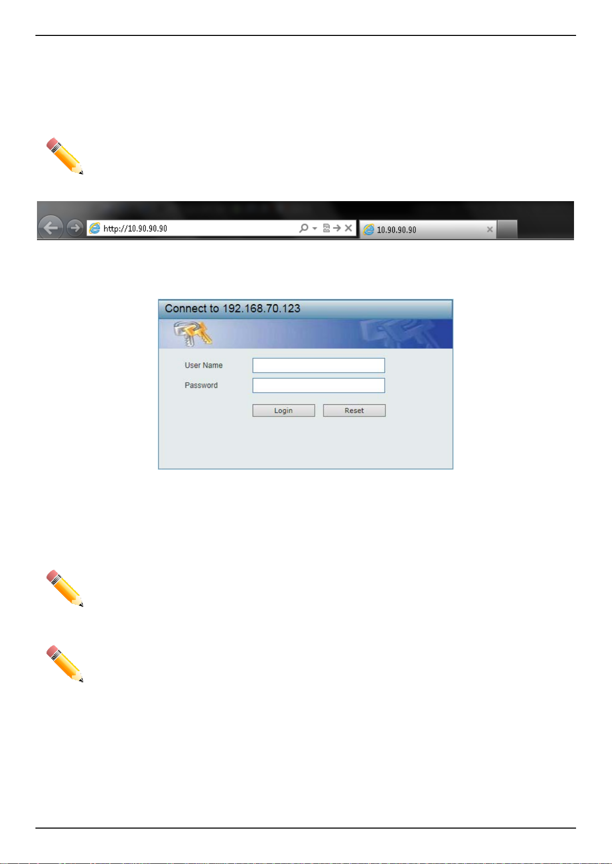
DGS-3630 Series Layer 3 Stackable Managed Switch Web UI Reference Guide
Logging into the Web UI
To access the Web UI open a standard web browser and ent er the IP address of the Switch into the address bar of
the browser and press the ENTER key.
NOTE: The factory default IP address of the Switch is 10.90.90.90 (subnet mask of 255.0.0.0) for
normal ports and 192.168.0.1 (subnet mask of 255.255.255.0) is for the management port.
Figure 2-1 Displays entering the IP address in Intern et Explorer
After pressing the ENTER key, the following aut hentication window should appear, as shown bel ow.
Figure 2-2 Web UI Login Window
When connecting to the Web UI of the Switch for the first time, leave the User Name and Password fields blank and
click Login since there are no login user accounts creat ed by default on the Switch.
NOTE: After a user account was created, login credentials will be required to access the Web UI.
During the sending and receiving of the login pa ssword to and from the Switch, this information
NOTE: The Switch only supports ASCII characters for input values.
will be protected using TLS/SSL to prevent attackers from sno oping this information to gain
unauthorized access to the Switch.
4
Page 17

DGS-3630 Series Layer 3 Stackable Managed Switch Web UI Reference Guide
AREA 3
AREA 1
AREA 4
AREA 2
Web User Interface (Web UI)
The Web UI provides access to various Switch configuration and management windows. It al l ows the user to view
performance statistics, and permits graphical monitoring of the system’s status.
Areas of the User Interface
The figure below shows the user interface. F our distinct areas that divide the user interfa ce, as described in the table.
Area Number Description
AREA 1
AREA 2
AREA 3
AREA 4
NOTE: The best screen resolution for viewing the Web UI is 1280 x 1024 pixel s.
This area displays a graphical, near real-time image of the front panel of the
Switch. This area displays the Switch’s ports and ex pansion modules. It also
shows port activity based on a specific mode. S om e management functions,
including port monitoring, are accessible from here.
Click the D-Link logo to go to the D-Link website.
This area displays a toolbar used to access Save and Tools menus.
This area displays a file explorer-type menu tree with all configurable options.
Select the folder or window to display. Open folders and click the hyperlinked
window buttons and subfolders contained withi n them to display information
pertaining to that category.
In this area, the Switch’s configuration page c an be found, based on the selection
made in AREA 3.
Figure 2-3 Main Web UI Window
5
Page 18

DGS-3630 Series Layer 3 Stackable Managed Switch Web UI Reference Guide
3. System
Device Information
System Information Settings
Peripheral Settings
Port Configuration
Loopback Test
System Log
Time and SNTP
Time Range
PTP (Precise Time Protocol)
USB Console Settings
SRM
Device Information
In the Device Information section, the us er can view a list of basic information regarding the Switch. It appears
automatically when you log on to the Switch. To return to the Device Information window after viewing other windows,
click the DGS-3630-28PC link.
Figure 3-1 Device Information Win dow
System Information Settings
This window is used to display and configure the system information settings and manageme nt interface configuration
settings.
6
Page 19
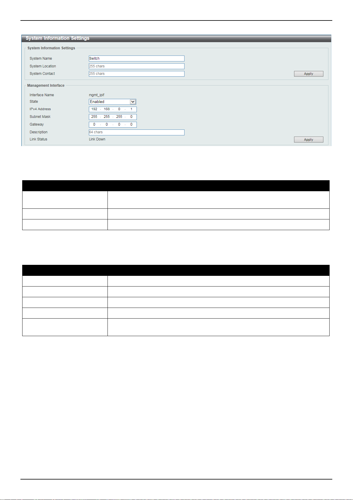
DGS-3630 Series Layer 3 Stackable Managed Switch Web UI Reference Guide
To view the following window, click System > System Information Settings, as shown below:
Figure 3-2 System Information Settings Window
The fields that can be configured in System Information Settings are described below:
Parameter Description
System Name
System Location
System Contact
Click the Apply button to accept the changes made.
The fields that can be configured in Management I nterface are described below:
Parameter Description
State
IPv4 Address
Subnet Mask
Gateway
Description
Click the Apply button to accept the changes made.
Enter a system name for the Switch, if so desired. This name will identify it in the
Switch network.
Enter the location of the Switch, if so desired.
Enter a contact name for the Switch, if so desired.
Select to enable or disable the state of the management interface here.
Enter the IPv4 address for this interface here.
Enter the IPv4 subnet mask for this interf ace here.
Enter the gateway IPv4 address for this interf ace here.
Enter the description for the management interface here. This can be up to 64
characters long.
Peripheral Settings
This window is used to display and configure the e nvironment trap settings and environment tem perature threshold
settings.
7
Page 20
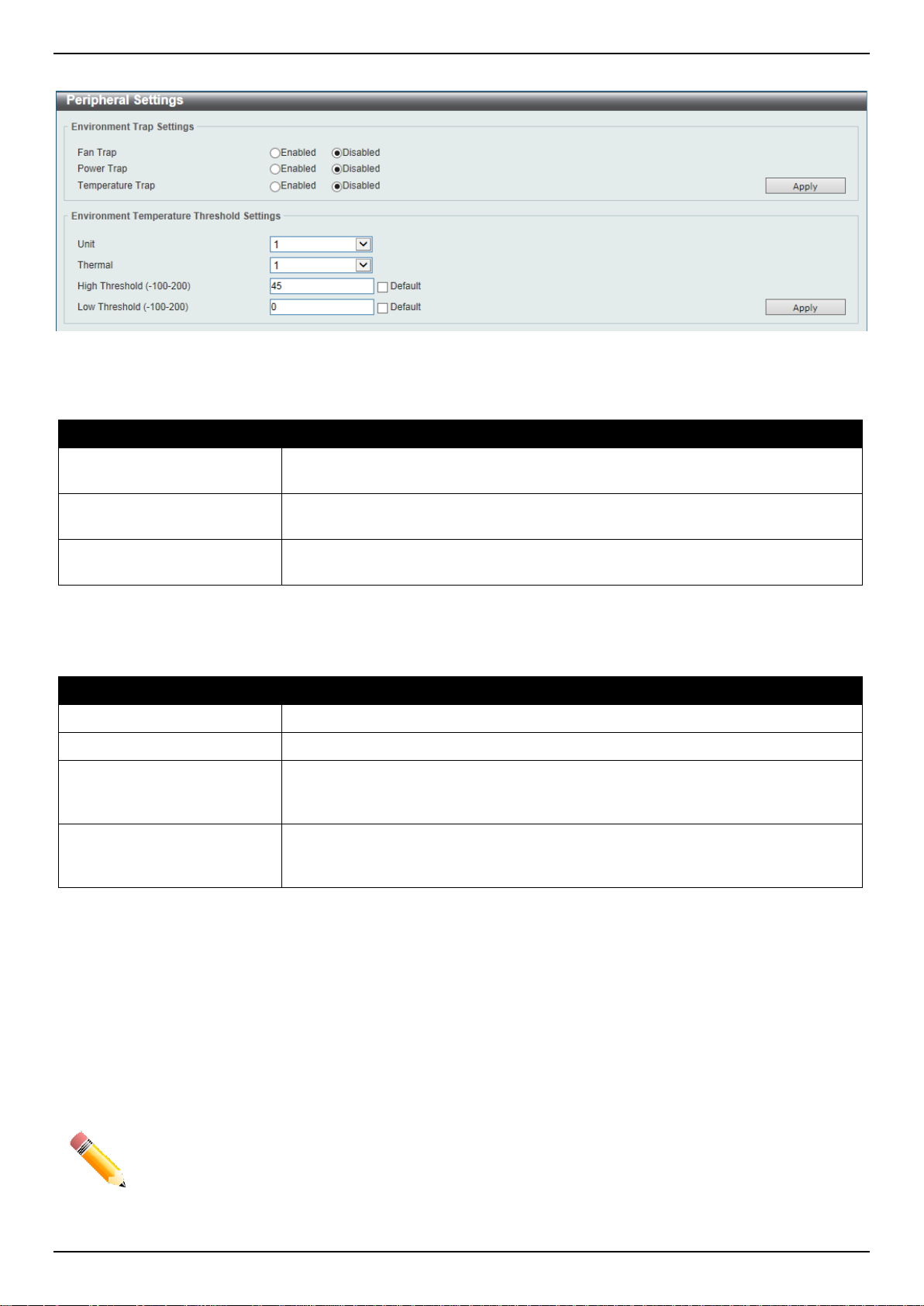
DGS-3630 Series Layer 3 Stackable Managed Switch Web UI Reference Guide
To view the following window, click System > Peripheral Settings, as shown below:
Figure 3-3 Peripheral Settings Window
The fields that can be configured in Environment Trap Settings a re described below:
Parameter Description
Fan Trap
Power Trap
Temperature Trap
Click the Apply button to accept the changes made.
The fields that can be configured in Environment Temperature Threshold Settings are described below:
Parameter Description
Unit
Thermal
High Threshold
Low Threshold
Click the Apply button to accept the changes made.
Select to enable or disable the fan trap state for waning fan event (fan f ail ed or
fan recover).
Select to enable or disable the power trap state for waning power event (power
failed or power recover).
Select to enable or disable the temperature trap state for warning temperature
event (temperature thresholds exceeded or temperature recover).
Select the Switch unit that will be used for this configurati on here.
Select the thermal sensor ID.
Enter the high threshold value of the warning t em perature setting. The range is
from -100 to 200 degrees Celsius. Tick the Default check box to return to the
default value.
Enter the low threshold value of the warning temperature setting. The range is
from -100 to 200 degrees Celsius. Tick the Default check box to return to the
default value.
Port Configuration
Port Settings
This window is used to display and configure the Switch’s port settings.
NOTE: The 10M and 100M speed options are only applicable when connecting to the Management
Port (Mgmt 0).
8
Page 21
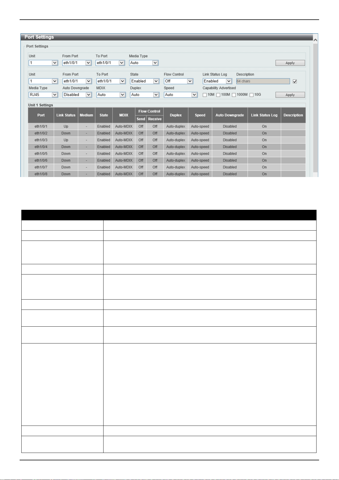
DGS-3630 Series Layer 3 Stackable Managed Switch Web UI Reference Guide
To view the following window, click System > Port Configuration > Port Settings, as shown below:
Figure 3-4 Port Settings Window
The fields that can be configured are described below:
Parameter Description
Unit
From Port - To Port
Media Type
Select the stacking unit ID of the Switch that will be configured here.
Select the appropriate port range used for the configuration here.
Select the port media type here. Options to choose from are Auto, RJ45, and
SFP. Selecting the SFP option includes the use of SFP+ tran sc ei vers for 10G
connectivity.
State
Flow Control
Select to enable or disable the physical port state here.
Select to turn flow control On or Off here. Ports configured for full-duplex use
802.3x flow control and Auto ports use an automatic selecti on of the two.
Note: This feature will not work through Switches that are physically stacked.
Link Status Log
Description
Select to enable or disable the link status log function here.
Select the checkbox and enter the description for t he cor responding port here.
This can be up to 64 characters long.
Auto Downgrade
Select to enable or disable the feature to automatically downgrade the advertised
speed in the event that a link cannot be established at the available speed.
MDIX
Select the Medium Dependent Interface Cros sov er (MDIX) option here. Options to
choose from are:
Duplex
Speed
• Auto - Select this option for auto-sensing of the optimal type of cabling.
• Normal - Select this option for normal cabling. If this option is selected, the
port is in the MDIX mode and can be connected to a PC NIC using a straightthrough cable or a port (in the MDI mode) on another Switch through a crossover cable.
• Cross - Select this option for cross-over cabling. If this option is selected, the
port is in the MDI mode and can be connected t o a port (in the MDIX mode)
on another Switch through a straight cable.
Select the duplex mode used here. Options to choo se from are Auto and Full.
Select the port speed option here. This option will manually force the connection
speed on the selected port to connect at the specifi ed speed only.
9
Page 22

DGS-3630 Series Layer 3 Stackable Managed Switch Web UI Reference Guide
The Master setting will allow the port to advertise capabilities related to duplex,
Parameter Description
speed and physical layer type. The master setting will also determine the master
and slave relationship between the two connected physical layers. This
relationship is necessary for establishing the timing control between the two
physical layers. The timing control is set on a mast er physical layer by a local
source.
The Slave setting uses loop timing, where the timing comes from a data st ream
received from the master. If one connection i s s et for master, the other side of the
connection must be set for slave. Any other configuration will result in a ‘link
down’ status for both ports.
Options to choose from are:
• Auto - Specifies that for copper ports, auto-negotiation wil l st art to negotiate
the speed and flow control with its link partner. F or fiber ports, autonegotiation will start to negotiate the clock a nd flow control with its link
partner.
• 10M - Specifies to force the port speed to 10 Mbps. This option is only
available for 10 Mbps copper connections.
• 100M - Specifies to force the port speed t o 100 M bps. This option is only
available for 100 Mbps copper connections.
• 1000M - Specifies to force the port speed t o 1 Gbps. This option is only
available for 1 Gbps fiber connections.
• 1000M Master - Specifies to force the port speed to 1 Gbps and operates as
the master, to facilitate the timing of transmit and receive operations. This
Capability Advertised
Click the Apply button to accept the changes made.
option is only available for 1 Gbps copper connect ions.
• 1000M Slave - Specifies to force the port speed t o 1 Gbps and operates as
the slave, to facilitate the timing of transm it and receive operations. This
option is only available for 1 Gbps copper connections.
• 10G - Specifies to force the port speed to 10 G bps. This option is only
available for 10 Gbps fiber connections.
• 10G Master - Specifies to force the port speed to 10 Gbps and operates as
the master, to facilitate the timing of transmit and receive operations. This
option is only available for 10 Gbps copper connect ions.
• 10G Slave - Specifies to force the port speed to 10 Gbps and operates as
the slave, to facilitate the timing of transm i t and receive operations. This
option is only available for 10 Gbps copper connecti ons.
When the Speed is set to Auto, these capabilities are advertised during autonegotiation.
Port Status
This window is used to view the Switch’s physical port status and settings.
10
Page 23
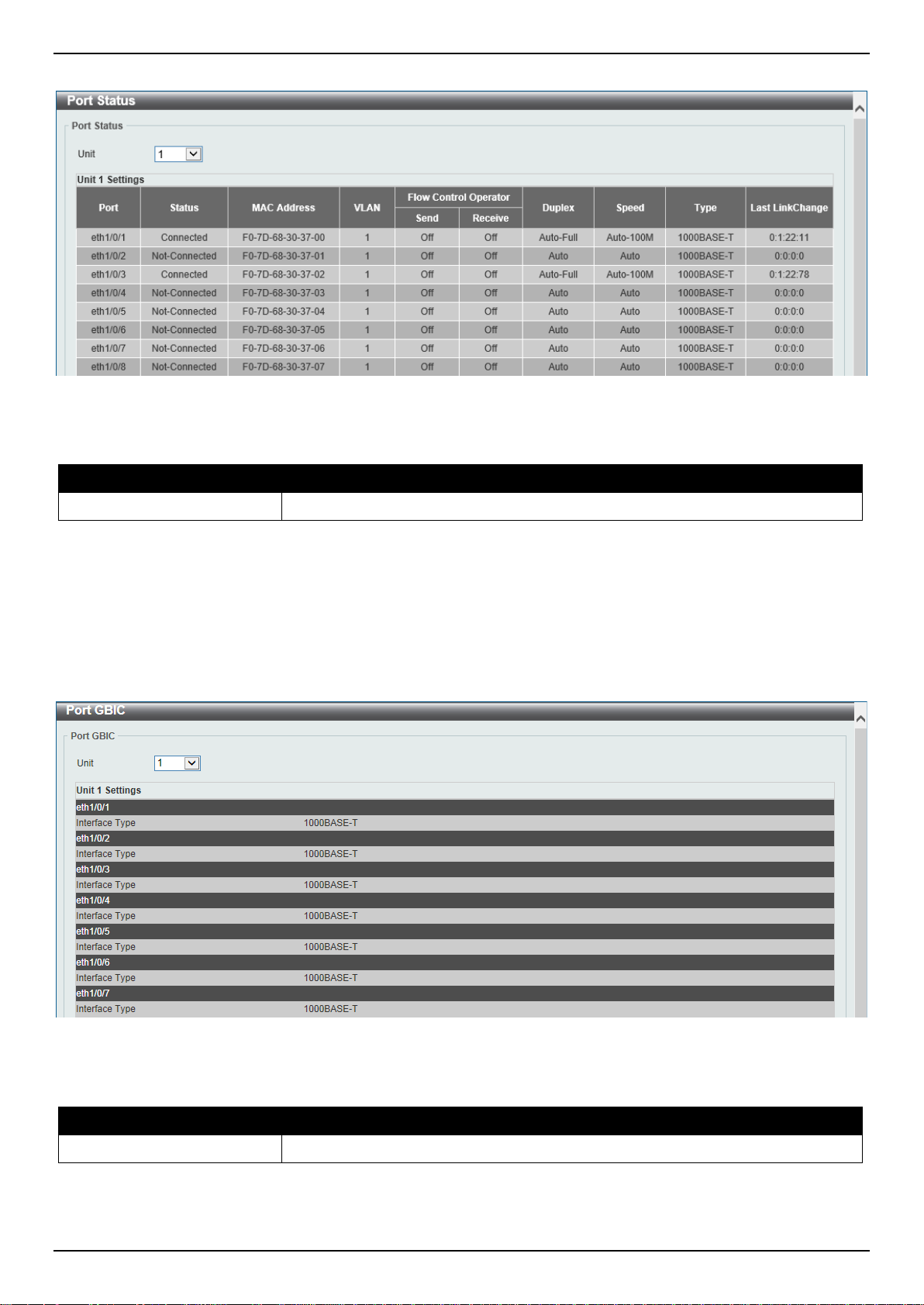
DGS-3630 Series Layer 3 Stackable Managed Switch Web UI Reference Guide
To view the following window, click System > Port Configuration > Port Status, as shown below:
Figure 3-5 Port Status Window
The fields that can be configured are described below:
Parameter Description
Unit
Select the stacking unit ID of the Switch that will be displayed here.
Port GBIC
This window is used to view active GBIC information found on each applicable physical port of this Switch.
To view the following window, click System > Port Configuration > Port GBIC, as shown below:
Figure 3-6 Port GBIC Window
The fields that can be configured are described below:
Parameter Description
Unit
Select the Switch unit that will be used for this display here.
11
Page 24
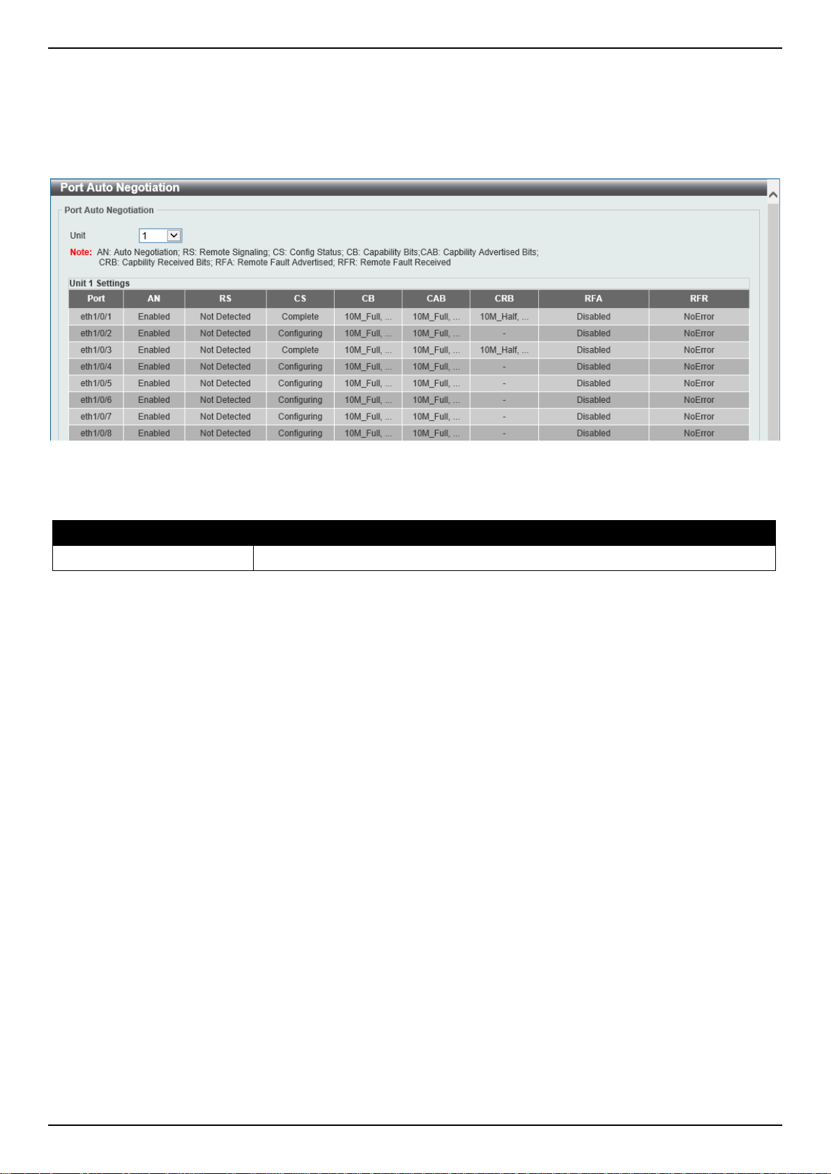
DGS-3630 Series Layer 3 Stackable Managed Switch Web UI Reference Guide
Port Auto Negotiation
This window is used to view detailed port auto-negotiation information.
To view the following window, click System > Port Configuration > Port Auto Negotiation, as shown below:
Figure 3-7 Port Auto Negotiation Window
The fields that can be configured are described below:
Parameter Description
Unit
Select the stacking unit ID of the Switch that will be displayed here.
Error Disable Settings
This window is used to display and configure the recovery from the Error Disable causes and to configure the recovery
interval.
12
Page 25
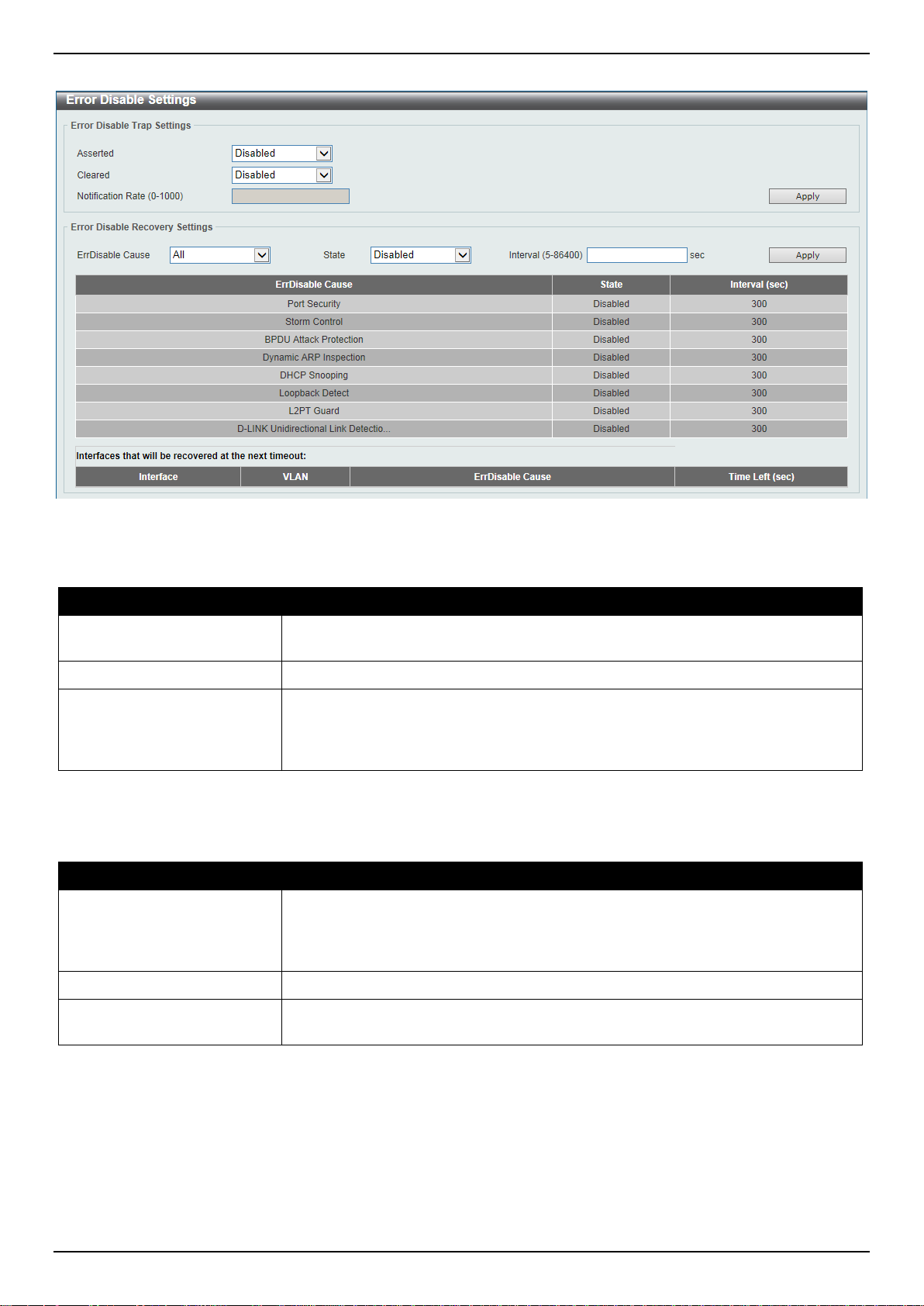
DGS-3630 Series Layer 3 Stackable Managed Switch Web UI Reference Guide
To view the following window, click System > Port Configuration > Error Disable Settings, as shown below:
Figure 3-8 Error Disable Settings Window
The fields that can be configured for Error Disable Trap Settings are de scribed below:
Parameter Description
Asserted
Cleared
Notification Rate
Click the Apply button to accept the changes made.
The fields that can be configured for Error Disable Recovery Settings are describ ed below:
Parameter Description
ErrDisable Cause
Specifies to enable or disable notifications for e ntering into the error disabled
state.
Specifies to enable or disable notifications for exi ting from the error disabled state.
Enter the notification rate value here. This sets the number of traps per minute.
The packets that exceed the rate will be dropped. The range is from 0 to 1000.
The default value (0) indicates that an SNMP trap will be generated for every
change of the error disabled state.
Select the error disabled cause here. Options to choose from are Port Security,
Storm Control, BPDU Attack Protection, Dynamic ARP Inspection, DHCP
Snooping, Loopback Detect, L2PT Guard, and D-Link Unidirectional Link
Detection.
State
Interval
Click the Apply button to accept the changes made.
Select to enable or disable the error disabled recovery feature here.
Enter the time, in seconds, to recover the port from th e error state caused by the
specified module. The range is from 5 to 86400.
Jumbo Frame
This window is used to display and configure the jumbo frame size and settings. The Switch supports jumbo fram es.
Jumbo frames are Ethernet frames with more tha n 1,518 bytes of payload. The Switch supports jumbo frames with a
maximum frame size of up to 12,288 bytes.
13
Page 26
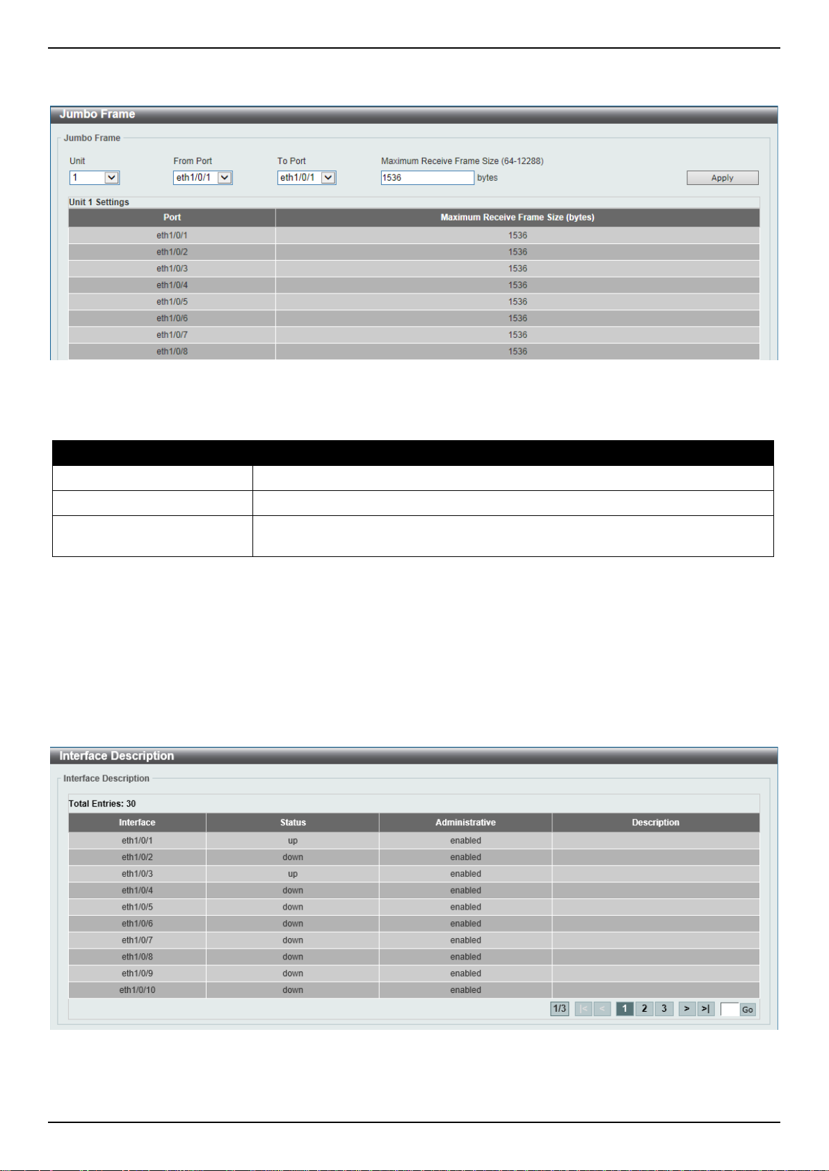
DGS-3630 Series Layer 3 Stackable Managed Switch Web UI Reference Guide
To view the following window, click System > Port Configuration > Jumbo Frame, as shown below:
Figure 3-9 Jumbo Frame Window
The fields that can be configured are described below:
Parameter Description
Unit
From Port - To Port
Maximum Receive Frame
Size
Click the Apply button to accept the changes made.
Select the stacking unit ID of the Switch that will be configured here.
Select the appropriate port range used for the configuration here.
Enter the maximum receive frame size value her e. This value must be between
64 and 12288 bytes. By default, this value is 1536 by tes.
Interface Description
This window is used to display the status, administrative status, and description of each p ort on the Switch.
To view the following window, click System > Interface Description, as shown below:
Figure 3-10 Interface Description Win dow
Enter a page number and click the Go button to navigate to a specific page when multiple pages exist.
14
Page 27
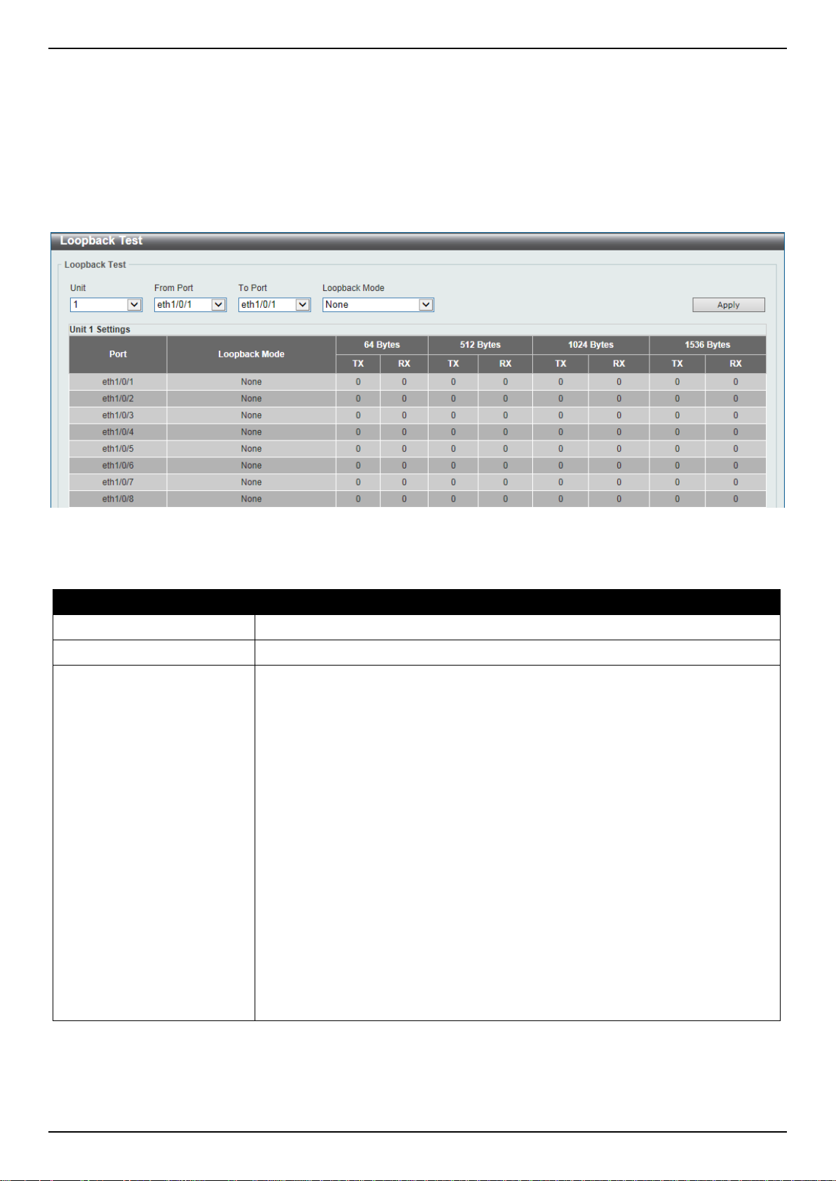
DGS-3630 Series Layer 3 Stackable Managed Switch Web UI Reference Guide
Loopback Test
This window is used to display and configure the loopback settings of the physical port interfaces and to perform
loopback tests.
To view the following window, click System > Loopback Test, as shown below:
Figure 3-11 Loopback Settings Window
The fields that can be configured are described below:
Parameter Description
Unit
From Port - To Port
Loopback Mode
Select the Switch unit that will be used for this configurati on here.
Select the appropriate port range used for the conf i guration here.
Select the loopback mode here. Options to choo se f rom are:
• None - Specifies not to enable the loopback mode.
• Internal MAC - Specifies the internal loopback mode at the MAC layer.
• Internal PHY Default - Specifies the internal loopback mode at the PHY
layer to test the default medium.
• Internal PHY Copper - Specifies the internal loopback mode at the PHY
layer to test the copper medium.
• Internal PHY Fiber - Specifies the internal loopback mode at the PHY layer
to test the fiber medium.
• External MAC - Specifies the external loopb ack mode at the MAC layer.
• External PHY Default - Specifies the external loopback mode at the PHY
layer to test the default medium.
• External PHY Copper - Specifies the external loopback mode at the PHY
layer to test the copper medium.
• External PHY Fiber - Specifies the external loopback mode at the PHY layer
to test the fiber medium.
Click the Apply button to accept the changes made.
15
Page 28
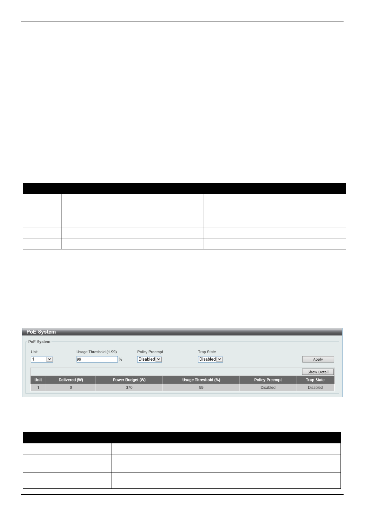
DGS-3630 Series Layer 3 Stackable Managed Switch Web UI Reference Guide
(PD) which is power-provisioned with a lower priority in order t o release the power
PoE
The DGS-3630-28PC and DGS-3630-52PC switches support Power over Ethernet (PoE) as defined by the IEEE
802.3af and 802.3at. All ports can support PoE up to 30W. The Switch ports can supply about 48 VDC power to
Powered Devices (PDs) over Category 5 or Category 3 UTP Ethernet cables. The Switch follows the standard Power
Sourcing Equipment (PSE) pin-out Alternative A , whereby power is sent out over pins 1, 2, 3 and 6. The Swi tches
work with all D-Link 802.3af capable devices.
The Switch includes the following PoE features:
• Auto-discovery recognizes the connection of a PD and automatically sends power to it.
• The auto-disable feature occurs under two conditions:
If the total power consumption exceeds the system power limit
If the per-port power consumption exceeds the per port power limit
• Active circuit protection automatically disables the port if there is a short. Other ports wil l remain active.
Based on IEEE 802.3af/at, power is received and s upplied according to the following classificat ions:
Class Maximum power used by the PD Maximum power supplied by the Switch
0
1
2
3
4
12.95 Watts 16.2 Watts
3.84 Watts 4.2 Watts
6.49 Watts 7.4 Watts
12.95 Watts 16.2 Watts
25.5 Watts 31.6 Watts
PoE System
This window is used to configure the PoE system and display the detailed power information and PoE chip parameters
for PoE modules.
To view the following window, click System > PoE > PoE System, as shown below:
Figure 3-12 PoE System Window
The fields that can be configured for PoE System are described below:
Parameter Description
Unit
Usage Threshold
Policy Preempt
Select the stacking unit ID of the Switch that will be configured here.
Enter the usage threshold to generate a log and send the corresponding standard
notification. The range is from 1 to 99 percent.
Select this option to enable or disable the disconnection of the Powered Device
16
Page 29
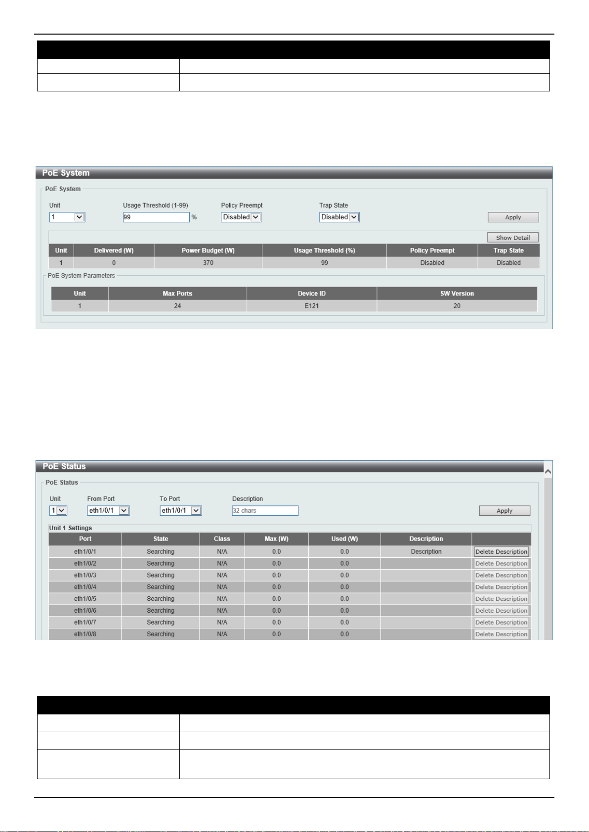
DGS-3630 Series Layer 3 Stackable Managed Switch Web UI Reference Guide
to the new connected PD with higher priority under power shortage conditions.
Parameter Description
Trap State
Click the Apply button to accept the changes made.
Click the Show Detail button to see the PoE system Parameters table at the bottom of the window.
After clicking the Show Detail button, the following window will appear.
Select this option to enable or disable the sending of PoE trap notifications.
Figure 3-13 PoE System (Show Detail) Window
PoE Status
This window is used to configure the description and display the PoE status of each port.
To view the following window, click System > PoE > PoE Status, as shown below:
Figure 3-14 PoE Status Window
The fields that can be configured for PoE Status are described below:
Parameter Description
Unit
From Port - To Port
Description
Select the stacking unit ID of the Switch that will be configured here.
Select the appropriate port range used for the configuration here.
Enter the text that describes the PD connected t o a P oE interface. The maximum
length is 32 characters.
17
Page 30
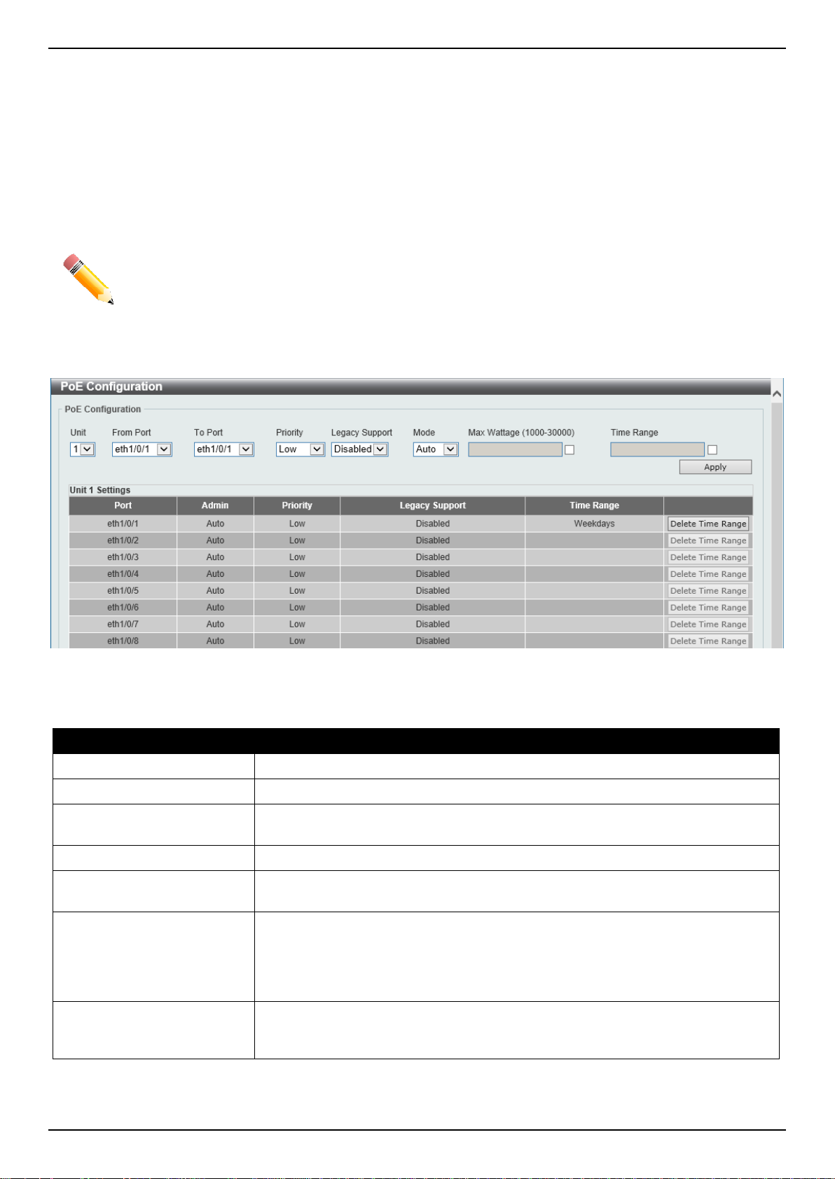
DGS-3630 Series Layer 3 Stackable Managed Switch Web UI Reference Guide
Click the Apply button to accept the changes made.
Click the Delete Description button to remove the description from the entry.
PoE Configuration
This window is used to display and configure the PoE configuration settings.
NOTE: If the Switch failed to supply power to the IEEE 802.3at Powered Device (PD),
• Check if the PD connected to the port support s the IEEE 802.3at standard
• Manually configure the PoE power limit value to 30 Watts for the corresponding port
To view the following window, click System > PoE > PoE Configuration, as shown below:
Figure 3-15 PoE Configuration Window
The fields that can be configured for PoE Configuration are des cribed below:
Parameter Description
Unit
From Port - To Port
Priority
Legacy Support
Mode
Max Wattage
Time Range
Select the stacking unit ID of the Switch that will be configured here.
Select the appropriate port range used for the configuration here.
Select the priority for provisioning power to the port. Options to choose from are
Critical, High and Low.
Select this option to enable or disable the support of legacy PD.
Select the power management mode for the PoE ports. Options to choose from
are Auto and Never.
When selecting Auto in the Mode drop-down list, this option appears. Tick the
check box and enter the maximum wattage of power that can be provisioned to
the auto-detected PD. If the value is not ent ered, the class of the PD automatically
determines the maximum wattage which can be provisioned. The valid range for
maximum wattage is between 1000 mW and 30000 mW.
When selecting Auto in the Mode drop-down list, this option appears. Tick the
check box and enter the name of the time range to determine the activation
period.
Click the Apply button to accept the changes made.
Click the Delete Time Range button remove the time range association for the entry.
18
Page 31

DGS-3630 Series Layer 3 Stackable Managed Switch Web UI Reference Guide
PD Alive
This window is used to display and configure the PoE PD alive settings. The PoE alive feature provides the solution
when PD devices stop working or are not responding using the ping mechanism.
To view the following window, click System > PoE > PD Alive, as shown below:
Figure 3-16 PD Alive Window
The fields that can be configured for PD Alive Configuration are described below:
Parameter Description
Unit
From Port - To Port
PD Alive State
PD IP Address
Poll Interval
Retry Count
Waiting Time
Action
Select the stacking unit ID of the Switch that wil l be configured here.
Select the appropriate port range used for the configuration here.
Select to enable or disable the state of the PoE ali ve function on the specified
port(s) here.
Enter the IPv4 address of the target PD here.
Enter the poll interval value here. The range is f rom 10 to 300 seconds. This is the
interval at which ping requests will be sent to the target PD to check the status.
Enter the retry count value here. The range is from 0 to 5. This is the amount of
times that the ping request will be resend if the target PD does not respond.
Enter the waiting time value here. The range is from 30 to 300 seconds. This is
the time the Switch will wait for the PD to recover from rebooting.
Select the action that will be taken here. Opt i ons to choose from are:
• Reset - Specifies to reset the PoE port state.
• Notify - Specifies to send logs and traps to notify the administrator.
• Both - Specifies to send logs and traps and then to reset the PoE port
state.
Click the Apply button to accept the changes made.
PoE Statistics
This window is used to display and clear the PoE statistics on the Switch ports.
19
Page 32

DGS-3630 Series Layer 3 Stackable Managed Switch Web UI Reference Guide
To view the following window, click System > PoE > PoE Statistics, as shown below:
Figure 3-17 PoE Statistics Window
The fields that can be configured for PoE Statistics Table are described below:
Parameter Description
Unit
Click the Clear All button to clear PoE statistics for all ports.
Click the Clear button to clear the PoE statistics for the corresponding port.
Select the stacking unit ID of the Switch that will be used here.
PoE Measurement
This window is used to display the PoE measurement information on the Switch ports.
To view the following window, click System > PoE > PoE Measurement, as shown below:
Figure 3-18 PoE Measurement Window
The fields that can be configured for PoE Measurement Table are described below:
Parameter Description
Unit
Select the stacking unit ID of the Switch that will be used here.
20
Page 33

DGS-3630 Series Layer 3 Stackable Managed Switch Web UI Reference Guide
PoE LLDP Classification
This window is used to display the PoE Link Layer Discovery Protocol (LLDP) classification.
To view the following window, click System > PoE > PoE LLDP Classification, as shown below:
Figure 3-19 PoE LLDP Classification Window
The fields that can be configured for PoE LLDP Classification Table are described below:
Parameter Description
Unit
Select the stacking unit ID of the Switch that will be used here.
System Log
System Log Settings
This window is used to display and configure the sy stem log settings.
21
Page 34

DGS-3630 Series Layer 3 Stackable Managed Switch Web UI Reference Guide
To view the following window, click System > System Log > System Log Settings, as shown below:
Figure 3-20 System Log Settings Window
The fields that can be configured for Log State are described below:
Parameter Description
Log State
Select the enable or disable the global system l og st ate here.
Click the Apply button to accept the changes made.
The fields that can be configured for Source Interface Settings are described below:
Parameter Description
Source Interface State
Type
Select this option to enable or disable the global sou rce interf ace s tat e.
Select the type of interface that will be used. Opt i ons to choose from are
Loopback, Mgmt, and VLAN.
Interface ID
Enter the interface ID used here. For loopback interfaces this ID can be from 1 to
8. For the management (Mgmt) interface this value is always 0. For V LAN
interfaces this value is from 1 to 4094.
Click the Apply button to accept the changes made.
22
Page 35

DGS-3630 Series Layer 3 Stackable Managed Switch Web UI Reference Guide
The fields that can be configured for Buffer Log Settings are described below:
Parameter Description
Buffer Log State
Select to globally enable or disable the buffer log state here. Options to choose
from are Enable, Disabled, and Default. When selecting the Default option, the
global buffer log state will follow the default behavior.
Severity
Select the severity value of the type of informati on that will be logged. Options to
choose from are 0 (Emergencies), 1 (Alerts), 2 (Critical), 3 (Errors), 4
(Warnings), 5 (Notifications), 6 (Inform ational ), and 7 (Debugging).
Discriminator Name
Enter the discriminator name used here. This nam e can be up to 15 characters
long. This specifies the name of the discriminator profile that will be used to filter
buffer log messages based on the filtering criteria specifi ed within t hat profile.
Write Delay
Enter the log write delay value here. This value m ust be between 0 and 65535
seconds. By default, this value is 300 second s. T ick the Infinite option, to disable
the write delay feature.
Click the Apply button to accept the changes made.
The fields that can be configured for Console Log Settings are described below:
Parameter Description
Console Log State
Severity
Select to globally enable or disable the console log state here.
Select the severity value of the type of informati on that will be logged. Options to
choose from are 0 (Emergencies), 1 (Alerts), 2 (Critical), 3 (Errors), 4
(Warnings), 5 (Notifications), 6 (Inform ational ), and 7 (Debugging).
Discriminator Name
Enter the discriminator name used here. This name can be up to 15 characters
long. This specifies the name of the discriminator profile that will be used to filter
console log messages based on the filtering crite ria spe cifi ed with in that profile.
Click the Apply button to accept the changes made.
The fields that can be configured for SMTP Log Settings are described below:
Parameter Description
SMTP Log State
Severity
Select to globally enable or disable the SMTP l og st ate here.
Select the severity value of the type of informati on that will be logged. Options to
choose from are 0 (Emergencies), 1 (Alerts), 2 (Critical), 3 (Errors), 4
(Warnings), 5 (Notifications), 6 (Inform ational ), and 7 (Debugging).
Discriminator Name
Enter the discriminator name used here. This name can be up to 15 characters
long. This specifies the name of the discriminator profile that will be used to filter
SMTP log messages based on the filtering criteria specified within that profile.
Click the Apply button to accept the changes made.
The fields that can be configured for Monitor Log Settings are described below:
Parameter Description
Monitor Log State
Severity
Select to globally enable or disable the monitor log state here.
Select the severity value of the type of informati on that will be logged. Options to
choose from are 0 (Emergencies), 1 (Alerts), 2 (Critical), 3 (Errors), 4
(Warnings), 5 (Notifications), 6 (Inform ational ), and 7 (Debugging).
Discriminator Name
Enter the discriminator name used here. This name can be up to 15 characters
long. This specifies the name of the discriminator profile that will be used to filter
monito log messages based on the filtering criteria specified within that profile.
Click the Apply button to accept the changes made.
23
Page 36

DGS-3630 Series Layer 3 Stackable Managed Switch Web UI Reference Guide
System Log Discriminator Settings
This window is used to display and configure the syst em log disc rim inator sett in gs.
To view the following window, click System > System Log > System Log Discriminator Settings, as shown below:
Figure 3-21 System Log Discriminator Settings Window
The fields that can be configured are described below:
Parameter Description
Discriminator Name
Action
Severity
Click the Apply button to accept the changes made.
Click the Delete button to delete the specified entry.
Enter the name of the discriminator profile here. This name can be up to 15
characters long.
Select the facility behavior option and the type of facility that will be associated
with the selected behavior here. Behavior option s t o choose from are Drops and
Includes.
Select the severity behavior option and the value of the type of i nformation that
will be logged. Behavior options to choose from a re Drops and Includes. Severity
value options to choose from are 0 (Emergencies), 1 (Alerts), 2 (Critical), 3
(Errors), 4 (Warnings), 5 (Notifications), 6 (Informational), and 7 (Debugging).
System Log Server Settings
This window is used to display and configure the system log server settings.
24
Page 37

DGS-3630 Series Layer 3 Stackable Managed Switch Web UI Reference Guide
To view the following window, click System > System Log > System Log Server Settings, as shown below:
Figure 3-22 System Log Server Settings Window
The fields that can be configured are described below:
Parameter Description
Host IPv4 Address
Host IPv6 Address
UDP Port
Severity
Facility
Enter the system log server IPv4 address here.
Enter the system log server IPv6 address here.
Enter the system log server UDP port number here. This value must be either 514
or between 1024 and 65535. By default, this val ue is 514.
Select the severity value of the type of informati on that will be logged. Options to
choose from are 0 (Emergencies), 1 (Alerts), 2 (Critical), 3 (Errors), 4
(Warnings), 5 (Notifications), 6 (Informational), and 7 (Debugging).
Select the facility number that will be logged here. The range is from 0 to 23. Each
facility number is associated with a specific facil ity. See the table below:
Facility Number Facility Name Facility Description
0
1
2
3
4
5
kern Kernel messages
user User-level messages
mail Mail system
daemon System daemons
auth1 Security/authorization messages
syslog Messages generated internally by the
SYSLOG
6
lpr Line printer sub-system
7
8
9
10
11
12
13
14
15
16
17
18
news Network news sub-system
uucp UUCP sub-system
clock1 Clock daemon
auth2 Security/authorization messages
ftp FTP daemon
ntp NTP subsystem
logaudit Log audit
logalert Log alert
clock2 Clock daemon
local0 Local use 0 (local0)
local1 Local use 1 (local1)
local2 Local use 2 (local2)
25
Page 38

DGS-3630 Series Layer 3 Stackable Managed Switch Web UI Reference Guide
Parameter Description
19
20
21
22
23
Discriminator Name
VRF Name
Click the Apply button to accept the changes made.
Click the Delete button to delete the specified entry.
Enter the name of the discriminator that will be used to filter messages sent to the
log server here. This name can be up to 15 characters long.
Enter the name of the Virtual Routing and Forwarding (VRF) instance here. This
name can be up to 12 characters long.
local3 Local use 3 (local3)
local4 Local use 4 (local4)
local5 Local use 5 (local5)
local6 Local use 6 (local6)
local7 Local use 7 (local7)
System Log
This window is used to view and clear the system log.
To view the following window, click System > System Log > System Log, as shown below:
Figure 3-23 System Log Window
Click the Clear Log button to clear the system log entries displ ayed in the table.
Enter a page number and click the Go button to navigate to a specific page when multiple pages exist.
System Attack Log
This window is used to view and clear the system at tack log.
26
Page 39

DGS-3630 Series Layer 3 Stackable Managed Switch Web UI Reference Guide
To view the following window, click System > System Log > System Attack Log, as shown below:
Figure 3-24 System Attack Log Window
The fields that can be configured are described below:
Parameter Description
Unit
Click the Clear Attack Log button to clear the system att ack log entries displayed in the table.
Select the stacking unit ID of the Switch that will be displayed here.
Time and SNTP
Clock Settings
This window is used to display and configure the time settings for the Switch.
To view the following window, click System > Time and SNTP > Clock Settings, as shown below:
Figure 3-25 Clock Settings Window
The fields that can be configured are described below:
Parameter Description
Time
Date
Click the Apply button to accept the changes made.
Enter the current time in hours (HH), minutes (MM), and seconds (SS) here. For
example, 18:30:30.
Enter the current day (DD), month (MM), and year (YYYY) here. For example,
30/04/2015.
Time Zone Settings
This window is used to display and configure time zones and Daylight Savings Time settings for S NTP .
27
Page 40

DGS-3630 Series Layer 3 Stackable Managed Switch Web UI Reference Guide
To view the following window, click System > Time and SNTP > Time Zone Settings, as shown below:
Figure 3-26 Time Zone Settings Window
The fields that can be configured are described bel ow:
Parameter Description
Summer Time State
Select the summer time setting. Options t o choose from are Disabled, Recurring
Setting, and Date Setting.
• Disabled - Select to disable the summer ti m e set ting.
• Recurring Setting - Select to configure the summer time that should start
and end on the specified week day of the specified month.
• Date Setting - Select to configure the summer ti m e that should start and end
on the specified date of the specified month.
Time Zone
Select to specify your local time zone offset from Coordinated Universal Time
(UTC).
The fields that can be configured in Recurring Settings are d escribed below:
Parameter Description
From: Week of the Month
Select week of the month that summer time will start.
From: Day of the Week
From: Month
Select the day of the week that summer time will st art.
Select the month that summer time will start.
28
Page 41

DGS-3630 Series Layer 3 Stackable Managed Switch Web UI Reference Guide
Parameter Description
From: Time
To: Week of the Month
To: Day of the Week
To: Month
To: Time
Offset
The fields that can be configured in Date Settin g s are described below:
Parameter Description
From: Date of the Month
From: Month
From: Year
From: Time
To: Date of the Month
To: Month
To: Year
Select the time of the day that summer time will st art.
Select week of the month that summer time will end.
Select the day of the week that summer time will end.
Select the month that summer time will end.
Select the time of the day that summer time will end.
Enter the number of minutes to add during summer time. The def ault value is 60.
The range of this offset is 30, 60, 90 and 120.
Select date of the month that summer time will start.
Select the month that summer time will start.
Enter the year that the summer time will start .
Select the time of the day that summer time will st art.
Select date of the month that summer time will end.
Select the month that summer time will end.
Enter the year that the summer time will end.
To: Time
Offset
Click the Apply button to accept the changes made.
Select the time of the day that summer time will end.
Enter the number of minutes to add during summer time. The default value is 60.
The range of this offset is 30, 60, 90 and 120.
SNTP Settings
The Simple Network Time Protocol (SNTP) is a protocol for synchronizing computer clocks through the Internet. It
provides comprehensive mechanisms to acc ess national time and frequency dissemination serv i ces, coordinate the
SNTP subnet of servers and clients, and adjust t he system clock on each participant.
This window is used to display and configure the SNTP settings for the Switch.
To view the following window, click System > Time and SNTP > SNTP Settings, as shown below:
Figure 3-27 SNTP Settings Window
29
Page 42

DGS-3630 Series Layer 3 Stackable Managed Switch Web UI Reference Guide
The first drop-down menu selects the hour and the second drop-down menu
The fields that can be configured in SNTP Global Settings are described below:
Parameter Description
SNTP State
Poll Interval
Click the Apply button to accept the changes made.
The fields that can be configured in SNTP Server Settings are described below:
Parameter Description
IPv4 Address
IPv6 Address
VRF Name
Click the Add button to add the SNTP server.
Click the Delete button to remove the specified entry.
Select this option to enable or disable SNTP.
Enter the synchronizing interval in seconds. The value is from 30 to 99999
seconds. The default interval is 720 seconds.
Enter the IPv4 address of the SNTP server which provides the SNTP reference.
Enter the IPv6 address of the SNTP server whi ch provides the SNTP reference.
Enter the name of the VRF instance here. This name can be up to 12 characters
long.
Time Range
This window is used to display and configure the ti m e profile settings.
To view the following window, click System > Time Range, as shown below:
Figure 3-28 Time Range Window
The fields that can be configured are described below:
Parameter Description
Range Name
From Week ~ To Week
From Time ~ To Time
Enter the time profile range name here. This nam e can be up to 32 characters
long.
Select the starting and ending days of the week t hat will be used for this time
profile. Tick the Daily option to use this time profile for every day of the week. Tick
the End Week Day option to use this time profile fro m the starting day of the
week until the end of the week.
Select the starting and ending time of the day that will be used for this time profile.
30
Page 43

DGS-3630 Series Layer 3 Stackable Managed Switch Web UI Reference Guide
selects the minute.
Parameter Description
Click the Apply button to accept the changes made.
Click the Find button to locate a specific entry based on the information enter ed.
Click the Delete Periodic button to delete the periodic entry.
Click the Delete button to delete the specified entry.
PTP (Precise Time Protocol)
The Precision Time Protocol (PTP) system is able to synchronize the distributed clocks with an accuracy of less than
1 microsecond via Ethernet networks.
PTP is a technology that enables precise synchronization of clocks in network systems. PTP is applicable to systems
communicating by Local Area Networks supporti ng multicast messaging including Ethernet an d UDP. PTP enables
heterogeneous systems that include clocks of various inherent precision, resolution and stabil ity to synchronize to a
grandmaster clock.
The synchronization is divided into two processes. The Best Master Clock (BMC) algorithm determines the PTP status
(master/slave) of all local ports. The syn chronization algorithm computes the clock offset between the master and
slave clock. There are two mechanisms, Delay Request-response Mechanism and Peer Delay M echanism, for
measuring the propagation time of an ev ent message.
The PTP system has three types of PTP device s, boundary clock, end-to-end transparent clock, and peer-to-peer
transparent clock. Only the boundary clock can participate in the selection of the best master clock.
When the stacking mode is enabled and the member ports of a trunk group exists in different stac k units, the PTP
function will:
• Execute normally when the sending and receiving of PTP messages are to member ports that are on the same
stack unit.
• Execute abnormally, when the sending and receivi ng of PTP messages are to member ports that are on
different stack units.
PTP Global Settings
This window is used to display and configure the global Precise Time Protocol (PTP) settings.
To view the following window, click System > PTP (Precise Time Protocol) > PTP Global Settings, as shown below:
Figure 3-29 PTP Global Settings Window
31
Page 44

DGS-3630 Series Layer 3 Stackable Managed Switch Web UI Reference Guide
The fields that can be configured in PTP Global Settings are described below:
Parameter Description
PTP State
PTP Mode
PTP Transport Protocol
Select to enable or disable the PTP feature here. W hen the PTP function is
enabled, the Switch port will add residence time to correct the field. When the
PTP function is disabled, all Switch ports will forward the PTP packets according
to the multicast filtering configuration.
Select the PTP mode here. Options to choose from are:
• Boundary - Specifies the Switch as a Boundary Clock.
• P2P Transparent - Specifies the Switch as a Peer-to-Peer Transparent
Clock. This is a clock that provides Precision Tim e Protocol (PTP) event
transit time information and also provides co rrections for the propagation
delay of the link. The link, in this case, is connected to the port that is
receiving the PTP event messages. Ports on peer-to-peer transparent clocks
use the peer delay mechanism to calculate the prop agation delay between
PTP ports.
• E2E Transparent - Specifies the Switch as an End-to-End Transparent
Clock. An End-to-End Transparent Clock supports the use of an end-to-end
delay measurement mechanism between the slave clock and the master
clock. Ports on end-to-end transparent clocks are i ndependent of
propagation delay mechanisms.
Select the PTP transport protocol here. Opt i ons to choose from are:
• Ethernet - Specifies the transport protocol of PTP as IEEE802.3 Ethernet.
• UDP - Specifies the transport protocol of P T P as UDP over IPv4.
Click the Apply button to accept the changes made.
The fields that can be configured in PTP Clock Domain Settings are described below:
Parameter Description
Unit
PTP Clock Domain Number
Select the Switch unit that will be used for this configurati on here.
Enter the PTP clock domain number here. All PTP messages, data sets, state
machines, and all other PTP entities are always associated with a particular
domain number. The range is from 0 to 127.
PTP Clock Domain Name
Enter the PTP clock domain name here. The name i s use d for user reference.
This name can be up to 32 characters long.
Click the Apply button to accept the changes made.
The fields that can be configured in PTP Boundary Clock Settings are described below:
Parameter Description
Priority 1
Enter the PTP boundary clock Priority 1 value her e. The priority 1 attribute is used
in the execution of the Best Master Clock algorithm. A lower value takes
precedence. Zero indicates the highest pre cedence. The range is from 0 to 255.
Priority 2
Enter the PTP boundary clock Priority 2 value her e. The priority 2 attribute is used
in the execution of the Best Master Clock algorithm. A lower value takes
precedence. In the event that the BMC algorithm f ails to order the clocks based
on the values of priority 1, the clock’s class, and the clock’s accuracy; the priority
2 attribute will allow the creation of lower values compared to the other devices.
Zero indicates the highest precedence. The range is from 0 to 255.
Click the Apply button to accept the changes made.
When the stacking mode is enabled and the member ports of the trunk group exist in different stack units, the PTP
function may not function properly.
32
Page 45

DGS-3630 Series Layer 3 Stackable Managed Switch Web UI Reference Guide
For example:
• The PTP feature will function properly when t he m ember ports receive and send PTP messages on t he same
stacked unit.
• The PTP feature will not function properly when t he member ports receive and send PTP messages on di fferent
stacked units.
Therefore, it is recommended not to enable the P T P feature on a trunk group that exists in diff erent stack units.
PTP Port Global Settings
This window is used to display and configure the PT P interface sett i ngs.
To view the following window, click System > PTP (Precise Time Protocol) > PTP Port Global Settings, as shown
below:
Figure 3-30 PTP Port Global Settings Window
The fields that can be configured are described below:
Parameter Description
Unit
From Port - To Port
State
Click the Apply button to accept the changes made.
Select the Switch unit that will be used for this configurati on here.
Select the range of ports that will be used for this configuration here.
Select to enable or disable the PTP feature on the p ort(s) specified here.
PTP Boundary Port Settings
This window is used to display and configure the attributes of the PTP boundary clock. The confi guration takes effect
when the PTP device is of the ‘boundary’ type.
33
Page 46

DGS-3630 Series Layer 3 Stackable Managed Switch Web UI Reference Guide
To view the following window, click System > PTP (Precise Time Protocol) > PTP Boundary Port Settings, as
shown below:
Figure 3-31 PTP Boundary Port Settings Window
The fields that can be configured are described below:
Parameter Description
Unit
From Port - To Port
Announce Interval
Select the Switch unit that will be used for this configurati on here.
Select the range of ports that will be used for this configuration here.
Enter the announce interval value here. This specifies the mean-time interval
between successive announce messages, referred to as the announce interval. In
line with the IEEE 1588 protocol, the value of the announce interval is
represented as the logarithm to the power of 2 of this time measured in seconds.
The range is from 1 to 16 seconds.
Announce Receipt Timeout
Enter the announce receipt timeout value here. This specifies the announce
interval number that has to pass without recei ving an announce message before
the ANNOUNCE_RECEIPT_TIMEOUT_EXPIRES event. This value is multiplied
by the announce interval value and is equal to the interval time of the announce
receipt timeout. The range is from 2 to 10.
Delay Mechanism
Select the delay mechanism here. Option to choose f rom are:
• E2E - This indicates that the port is configured to use the del ay request-
response mechanism.
• P2P - This indicates that the port is configured to use the peer delay
mechanism.
Delay Request Interval
Pdelay Request Interval
Enter the delay request interval value here. This specifies the permitted mean
time interval between successive delay reque st m essages which are sent by a
slave to a specific port on the master. This value is determined and advertised by
the master. In line with the IEEE 1588 protocol, the value of delay request interval
shall be an exponent of 2. In addition, this interval must be an integer with the
minimum value being the sync-interval, and the maximum v al ue being 32 times
the sync-interval value. If the sync-interval i s half a second and the delay request
interval is 0, then the permitted time interval between successive delay request
messages will be automatically adjusted to one second. The range is from 0 to 5.
Enter the peer delay request interval value here. This specifies the permitted
mean-time interval between successive peer delay request messages. In line with
the IEEE 1588 protocol, this value must be represented as the logarithm to the
base of 2 of this time, measured in seconds. The range is from 1 to 32 se conds.
34
Page 47

DGS-3630 Series Layer 3 Stackable Managed Switch Web UI Reference Guide
Parameter Description
Synchronization Interval
Click the Apply button to accept the changes made.
Enter the synchronization interval value here. This specifies the mean-time
interval between successive synchronization messages. In line with the IEEE
1588 protocol, this value must be represented as the logarithm to the base of 2 of
this time, measured in seconds. The range is from 1 to 2 seconds. Select the Half
Second option to set 0.5 seconds as this value.
PTP P2P Transparent Port Settings
This window is used to display and configure the p eer delay re quest message interval on the P2P transparent clock
port(s) specified.
To view the following window, click System > PTP (Precise Time Protocol) > PTP P2P Transparent Port Settings,
as shown below:
Figure 3-32 PTP P2P Transparent Port Settings Window
The fields that can be configured are described below:
Parameter Description
Unit
From Port - To Port
P2P Transparent Pdelay
Request Interval
Click the Apply button to accept the changes made.
Select the Switch unit that will be used for this configurati on here.
Select the range of ports that will be used for this configurati on here.
Enter the P2P transparent peer delay request i nterval value here. The range is
from 1 to 32.
PTP Clock Information
This window is used to view PTP clock information. This is used to display the active att ributes of the PTP clock.
35
Page 48

DGS-3630 Series Layer 3 Stackable Managed Switch Web UI Reference Guide
To view the following window, click System > PTP (Precise Time Protocol) > PTP Clock Information, as shown
below:
Figure 3-33 PTP Clock Information Window
The fields that can be configured are described below:
Parameter Description
Unit
Select the Switch unit that will be used here.
PTP Port Information
This window is used to view PTP port information.
To view the following window, click System > PTP (Precise Time Protocol) > PTP Port Information, as shown
below:
Figure 3-34 PTP Port Information Window
36
Page 49

DGS-3630 Series Layer 3 Stackable Managed Switch Web UI Reference Guide
The fields that can be configured are described below:
Parameter Description
Unit
Select the Switch unit that will be used here.
PTP Foreign Master Records Port Information
This window is used to view PTP Foreign Master Records port information.
To view the following window, click System > PTP (Precise Time Protocol) > PTP Foreign Master Records Port
Information, as shown below:
Figure 3-35 PTP Foreign Master Records Port Information Window
The fields that can be configured are described below:
Parameter Description
Unit
Select the Switch unit that will be used here.
USB Console Settings
This window is used to display and configure the USB console settings.
To view the following window, click System > USB Console Settings, as shown below:
Figure 3-36 USB Console Settings Window
The fields that can be configured are described below:
Parameter Description
USB Console State
USB Inactivity Timeout
Click the Apply button to accept the changes made.
Select to enable or disable the USB console state here.
Enter the USB inactivity timeout value here. The range is from 1 to 240 minutes.
Select the Active option to disable the timeout feature.
37
Page 50

DGS-3630 Series Layer 3 Stackable Managed Switch Web UI Reference Guide
NOTE: When an active console connection is made to both the RJ45 console p ort and the mini-USB
console port at the same time, the mini-USB con sole port will have higher priority.
SRM
The Switch Resource Management (SRM) feature provides a large number of resources t hat can be distributed and
optimized as needed by applications. It provides resource configuration flexibility that all ows users to allocate more
resources for tables that require more entries and prevents wasting resources on unused functions.
SRM Prefer Current Settings
This window is used to display and configure the SRM settings. This window is used to s pecify the SRM mode to be
used on the Switch for optimizing resources for various functions.
To view the following window, click System > SRM > SRM Prefer Current Settings, as shown below:
Figure 3-37 SRM Prefer Current Settings Window
The fields that can be configured are described below:
Parameter Description
SRM Prefer Mode
Click the Apply button to accept the changes made.
NOTE: When the SRM mode was modified and the Switch was rebooted, the table size will be
changed. If the number of static entries saved i n the startup configuration exceeds the number
NOTE: When Switches are physically stacked, ensure that all Switches in the stack are configured to
of static entries in the new table size, the exceeded number of entries will be removed.
use the same SRM mode.
Select the SRM prefer mode here. Options to choose from are:
• LAN - Specifies that the Switch prefers the LAN Switch mode.
• IP - Specifies that the Switch prefer the IP rout e m ode.
• L2VPN - Specifies that the Switch prefer the Layer 2 V P N m ode.
SRM Prefer Mode
This window is used to view the SRM preferred mod e settings. The entries in this table are fix ed values indicating the
maximum number of entries allowed per feature.
38
Page 51

DGS-3630 Series Layer 3 Stackable Managed Switch Web UI Reference Guide
To view the following window, click System > SRM > SRM Prefer Mode, as shown below:
Figure 3-38 SRM Prefer Mode Window
The fields that can be configured are described below:
Parameter Description
SRM Prefer Mode
Select the SRM prefer mode that will be used in the display here. Options to
choose from are LAN, IP, and L2VPN.
Click the Find button to generate the display based on the selections made.
39
Page 52

DGS-3630 Series Layer 3 Stackable Managed Switch Web UI Reference Guide
4. Management
Command Logging
User Accounts Settings
Password Encryption
Password Recovery
Login Method
SNMP
RMON
Telnet/Web
Session Timeout
DHCP
DHCP Auto Configuration
DHCP Auto Image Settings
DNS
NTP
IP Source Interface
File System
Stacking
Virtual Stacking (SIM)
D-Link Discovery Protocol
SMTP Settings
Reboot Schedule Settings
NLB FDB Settings
SD Card Management
Command Logging
This window is used to display and configure the command logging function. The command logging function is used to
log the commands that have successfully been configured on the Switch via the command line interface. The
command, along with information about t he user that entered the command, is included in the sy st em l og. Commands
that do not cause a change in the Switch configurat ion or operation (such as 'show' commands) are not l ogged.
To view the following window, click Management > Command Logging, as shown below:
Figure 4-1 Command Logging Window
The fields that can be configured are described below:
Parameter Description
Command Logging State
Click the Apply button to accept the changes made.
Select to enable or disable the command logging function here.
User Accounts Settings
On this page, user accounts can be created and updated. Active user account sessions can also be viewed on this
page.
40
Page 53

DGS-3630 Series Layer 3 Stackable Managed Switch Web UI Reference Guide
There are several configuration options available in the Web User Interface (Web UI). T he set of configuration options
available to the user depends on the account’s Privilege Level.
NOTE: By default, there are no user accounts created on the Switch.
To view the following window, click Management > User Accounts Settings, as shown below:
After selecting the User Management Settings tab, the following page will appear.
Figure 4-2 User Accounts Settings Window
The fields that can be configured are described below:
Parameter Description
User Name
Privilege
Password Type
Enter the user account name here. This name can be up to 32 characters long.
Enter the privilege level for this account here. T he range is from 1 to 15.
Select the password type for this user account here. Options to choose from are
None, Plain Text, Encrypted-SHA1, and Encrypted-MD5.
Password
After selecting Plain Text, Encrypted-SHA1, or Encrypted-MD5 as the
password type, enter the password for this user account here.
Click the Apply button to accept the changes made.
Click the Delete button to delete the specified user a cc ount entry.
Enter a page number and click the Go button to navigate to a specific page when multiple pages exist.
After selecting the Session Table tab, the following page will appear.
Figure 4-3 Session Table Window
On this page, a list of active user account ses sion will be displayed.
Click the Edit button to access and configure the User Level settings.
Enter a page number and click the Go button to navigate to a specific page when multiple pages exist.
41
Page 54

DGS-3630 Series Layer 3 Stackable Managed Switch Web UI Reference Guide
After selecting the Edit button, the following page will appear.
Figure 4-4 User Level Window
The fields that can be configured are described below:
Parameter Description
Action
Level
Password
Click the Apply button to accept the changes made.
Click the Back button to return to the previous page.
Select to enable or disable user level security.
Select the privilege level here. The range is from 1 to 15.
Enter the password here. This can be up to 35 characters long.
CLI Alias Settings
This window is used to display and configure the CLI alias settings. A CLI alias command is a custom st ring that can
be associated with a specific CLI command. This is useful if repeated use of long commands are needed in the CLI.
To view the following window, click Management > CLI Alias Settings, as shown below:
Figure 4-5 CLI Alias Settings Window
The fields that can be configured are described below:
Parameter Description
Mode
Alias Command
Original Command
Click the Apply button to accept the changes made.
Click the Find button to find and displays the CLI alias commands based on the command mode selected.
Click the Delete button to delete the specified entry.
Select the command mode of the original command here.
Enter the alias command here. This can be up to 16 c haracters long.
Enter the original command here. This can be up to 128 characters l ong.
42
Page 55

DGS-3630 Series Layer 3 Stackable Managed Switch Web UI Reference Guide
disabled to allow local authentication. The running configuration can then be
Enter a page number and click the Go button to navigate to a specific page when multiple pages exist.
Password Encryption
This window is used to display and configure whether to save the encryption of the password in the configuration file.
To view the following window, click Management > Password Encryption, as shown below:
Figure 4-6 Password Encryption Window
The fields that can be configured are described below:
Parameter Description
Password Encryption
State
Password Type
Click the Apply button to accept the changes made.
Select this option to enable or disable the encrypt i on of the password before being
stored in the configuration file.
When the state is enabled, select the passwo rd encryption type here. Options to
choose from are:
• Encrypted-SHA1 - Specifies that the password is encrypted using SHA-1.
• Encrypted-MD5 - Specifies that the password is encrypted using MD5.
Password Recovery
This window is used to display and configure the p assword recovery settings. For example, the admi nistrator may
need to update a user account because the passwo rd has been forgotten.
To view the following window, click Management > Password Recovery, as shown below:
Figure 4-7 Password Reco very Window
The fields that can be configured are described below:
Parameter Description
Password Recovery State
Select to enable or disable the password recovery feature here. Enabling this
feature allows access to the reset configuration mode in the CLI. From the reset
configuration mode, user accounts can be updated, the enable password feature
can be updated for administrator privilege level s, and the AAA feature can be
43
Page 56

DGS-3630 Series Layer 3 Stackable Managed Switch Web UI Reference Guide
saved as the startup configuration. A reboot is required.
Parameter Description
Click the Apply button to accept the changes made.
Login Method
This window is used to display and configure the login method for each management interfa ce that is supported by the
Switch.
To view the following window, click Management > Login Method, as shown below:
Figure 4-8 Login Method Window
The fields that can be configured in Enable Password are described below:
Parameter Description
Level
Password Type
Password
Click the Apply button to accept the changes made.
Click the Edit button to re-configure the specified entry.
Select the privilege level for the user here. The range is from 1 to 15.
Select the password type for the user here. Option s to choose from are:
• Plain Text - Specifies that the password will be in plain text. This is the
default option.
• Encrypted - Specifies that the password will be encr ypted based on SHA-1.
• Encrypted-MD5 - Specifies that the password will be encrypted ba sed on
MD5.
Enter the password for the user account here. In the plain-text form, the password
can be up to 32 characters long, is case-sensitive, an d can contain spaces. In the
encrypted form, the password must be 35 byt es long and is case-sensitive. In the
encrypted MD5 form, the password must be 31 bytes long and is case-sensitive.
44
Page 57

DGS-3630 Series Layer 3 Stackable Managed Switch Web UI Reference Guide
The fields that can be configured in Login Method are described below:
Parameter Description
Login Method
Click the Apply button to accept the changes made.
The fields that can be configured in Login Password are described below:
Parameter Description
Application
Password Type
Password
After clicking the Edit button, this parameter can be configured. S elect the login
method for the specified application here. O ptions to choose from are No Login,
Login and Login Local.
• No Login requires no login authentication t o acc ess the specified
application.
• Login will require the user to at least enter a password when trying to
access the application specified.
• Login Local requires the user to enter a usernam e and a password to
access the specified application.
Select the application that will be configured h ere. Options to choose from are
Console, Telnet and SSH.
Select the password encryption type that will be used here. Options to choose
from are Plain Text, Encrypted, and Encrypted-MD5.
Enter the password for the selected application here. This password will be used
when the Login Method for the specified application is set as Login. In the plaintext form, the password can be up to 32 characters long, is case-sensitive, and
can contain spaces. In the encrypted form, the password must be 35 bytes long
and is case-sensitive. In the encrypted MD5 form, t he password must be 31 bytes
long and is case-sensitive.
Click the Apply button to accept the changes made.
Click the Delete button to remove the password from t he specified application.
SNMP
Simple Network Management Protocol (SNMP) is an OSI Layer 7 (Application Layer) desi gned specifically for
managing and monitoring network devices. S NMP enables network management stations to read and modify the
settings of gateways, routers, switches, and other net wor k devices. Use SNMP to configure system feat ures, monitor
performance, and detect potential problems with the Switch, switch group, or network.
Managed devices that support SNMP include software (referred to as an agent) which runs locally on the device. A
defined set of variables (managed objects) is mai ntained by the SNMP agent and used to manage the dev i ce. T hese
objects are defined in a Management Inform ation Base (MIB), which provides a standard presentation of the
information controlled by the on-board SNMP agent. SNMP defines both the format of the MIB specifications and the
protocol used to access this information over t he network.
The Switch supports the SNMP versions 1, 2c, and 3. The three versions of SNMP vary in the level of security
provided between the management station and the network device.
In SNMPv1 and SNMPv2c, user authentication is accomplished using ‘community strings’, which function li ke
passwords. The remote user SNMP application and the Switch SNMP must use the same communi ty string. SNMP
packets from any station that has not been aut henticated are ignored (dropped). The default community strings for the
Switch used for SNMPv1 and SNMPv2c management access a re:
• public - Allows authorized management stations to retrieve MIB objects.
• private - Allows authorized management stations to retrieve and modify MIB objects.
45
Page 58

DGS-3630 Series Layer 3 Stackable Managed Switch Web UI Reference Guide
The SNMPv3 protocol uses a more sophisticated aut hentication process that is separated into two part s. T he first part
maintains a list of users and their attributes that are al lowed to act as SNMP managers. The second part describes
what each user in that list can do as an SNMP manager. The SNMPv3 protocol also provides an additional layer of
security that can be used to encrypt SNMP messages.
The Switch allows groups of users to be listed and configured with a shared set of privileges. The S NMP version may
also be set for a listed group of SNMP managers. Thus, you may create a group of SNMP managers that are allowed
to view read-only information or receive traps u sing SNMPv1 while assigning a higher level of se curit y to another
group, granting read/write privileges using S NM P v3.
Using SNMPv3, users or groups can be allowed or be prevented from performing specific SNMP management
functions. These are defined using the Object Identifier (OID) associated with a specific MIB.
MIBs
A Management Information Base (MIB) s tores management and counter information. The S witch uses the standard
MIB-II Management Information Base module, and so values for MIB objects can be retrieved using any SNMP-based
network management software. In addition to the st andard MIB-II, the Switch also supports its own proprietary
enterprise MIB as an extended Management Inf orm ation Base. Specifying the MIB Object Identifier may also retrieve
the proprietary MIB. MIB values can be either read-only or read-write.
The Switch incorporates a flexible SNMP m anagement system which can be customized to suit the needs of the
networks and the preferences of the network administrator. The three versions of SNM P vary in the level of security
provided between the management stati on and the network device. SNMP settings are config ured using the menus
located in the SNMP folder of the Web UI.
Traps
Traps are messages that alert network pers onnel of events that occur on the Switch. The events can be as serious as
a reboot (someone accidentally turned the Swi tch off/unplugged the Switch), or less serious like a port status change.
The Switch generates traps and sends them to the trap recipient (or network manager). Typical traps include trap
messages for Authentication Failure, Topology Change and Broadcast/Multicast Storm.
SNMP Global Settings
This window is used to display and configure the global SNMP and trap settings.
46
Page 59

DGS-3630 Series Layer 3 Stackable Managed Switch Web UI Reference Guide
To view the following window, click Management > SNMP > SNMP Global Settings, as shown below:
Figure 4-9 SNMP Global Settings Window
The fields that can be configured in SNMP Global Settings are described below:
Parameter Description
SNMP Global State
SNMP Response Broadcast
Request
SNMP UDP Port
Trap Source Interface
Select this option to enable or disable the SNMP feature.
Select this option to enable or disable the server t o response to broadcast SNMP
GetRequest packets.
Enter the SNMP UDP port number.
Enter the interface whose IP address will be used as the source address for
sending the SNMP trap packet.
The fields that can be configured in Trap Settings are described below:
Parameter Description
Trap Global State
Select this option to enable or disable the sending of all or specific SNMP
notifications.
SNMP Authentication Trap
Tick this option to control the sending of SNMP authentication failure notifications.
An authenticationFailuretrap trap is generated when the device receives an
SNMP message that is not properly authenticated. The authentication method
depends on the version of SNMP being used. For SNM P v1 or SNMPv2c,
authentication failure occurs if packets are formed with an incorrect community
string.
Port Link Up
Tick this option to control the sending of port link up notifications. A linkUp trap is
generated when the device recognizes that one of the communication links has
come up.
Port Link Down
Tick this option to control the sending of port link down notifications. A linkDown
trap is generated when the device recognizes that a one of the communication
links is down.
Coldstart
Warmstart
Tick this option to control the sending of SNMP coldStart notifications.
Tick this option to control the sending of SNMP warmStart notifications.
Click the Apply button to accept the changes made.
47
Page 60

DGS-3630 Series Layer 3 Stackable Managed Switch Web UI Reference Guide
SNMP Linkchange Trap Settings
This window is used to display and configure the SNMP link change trap settings.
To view the following window, click Management > SNMP > SNMP Linkchange Trap Settings, as shown below:
Figure 4-10 SNMP Linkchange Trap Settings Window
The fields that can be configured are described below:
Parameter Description
Unit
From Port - To Port
Trap Sending
Trap State
Click the Apply button to accept the changes made.
Select the Switch unit that will be used for this configurati on here.
Select the appropriate port range used for the configuration here.
Select this option to enable or disable the sending of the SNMP notification traps
that are generated by the system.
Select this option to enable or disable the SNMP linkChange trap.
SNMP View Table Settings
This window is used to assign views to communit y strings that define which MIB objects can be accessed by a remote
SNMP manager. The SNMP sub-tree OID created with this table maps SNMP users to the views created i n the SNMP
User Table Settings window.
48
Page 61

DGS-3630 Series Layer 3 Stackable Managed Switch Web UI Reference Guide
To view the following window, click Management > SNMP > SNMP View Table Settings, as shown below:
Figure 4-11 SNMP View Table Settings Window
The fields that can be configured are described below:
Parameter Description
View Name
Subtree OID
View Type
Click the Add button to add a new entry based on the information entered.
Click the Delete button to remove the specified entry.
Type an alphanumeric string of up to 32 characte rs. This is used to identify the
new SNMP view being created.
Type the Object Identifier (OID) sub-tree f or the view. The OID identifies an object
tree (MIB tree) that will be included or excluded from access by an SNMP
manager.
Select the view type here. Options to choose from are Included and Excluded.
• Included - Select to include this object in the list of objects that an SNMP
manager can access.
• Excluded - Select to exclude this object from the list of objects that an
SNMP manager can access.
SNMP Community Table Settings
This window is used to create an SNMP community string to define the relationship between t he SNMP manager and
an agent. The community string acts like a password to permit access to the agent on the Sw i tch. One or more of the
following characteristics can be associated with the community string:
• An access list containing IP addresses of SNMP managers that are permitted to use t he community string to
gain access to the Switch’s SNMP agent.
• Any MIB view that defines the subset of MI B object s that will be accessible to the SNMP community.
• Read-write or read-only level permissions for the MIB obje ct s accessible to the SNMP community.
49
Page 62

DGS-3630 Series Layer 3 Stackable Managed Switch Web UI Reference Guide
To view the following window, click Management > SNMP > SNMP Community Table Settings, as shown below:
Figure 4-12 SNMP Community Table Settings Window
The fields that can be configured are described below:
Parameter Description
Key Type
Community Name
View Name
Access Right
IP Access-List Name
Click the Add button to add a new entry based on the information entered.
Click the Delete button to remove the specified entry.
Select the key type for the SNMP community. Options to choose from are Plain
Text, and Encrypted.
Enter an alphanumeric string of up to 32 characters t hat is used to identify
members of an SNMP community. This string is used like a password to give
remote SNMP managers access to MIB object s in the Switch’s SNMP agent.
Enter an alphanumeric string of up to 32 characters t hat is used to identify the
group of MIB objects that a remote SNMP m anager is allowed to access on the
Switch. The view name must exist in the SNMP View Table.
Select the access right here. Options to choose from are Read Only and Read
Write.
• Read Only - SNMP community members using the community string created
can only read the contents of the MIBs on the Switch.
• Read Write - SNMP community members using the communit y string
created can read from, and write to the content s of the MIBs on the Switch.
Enter the name of the standard access list to restrict the users that can use this
community string to access to the SNMP agent.
SNMP Group Table Settings
An SNMP group created with this table maps SNMP users to the views created in the SNMP View Table Settings
window.
50
Page 63

DGS-3630 Series Layer 3 Stackable Managed Switch Web UI Reference Guide
To view the following window, click Management > SNMP > SNMP Group Table Settings, as shown below:
Figure 4-13 SNMP Group Table Settings Window
The fields that can be configured are described below:
Parameter Description
Group Name
Enter the SNMP group name here. This name can be up to 32 characters long.
Spaces are not allowed.
Read View Name
User-based Security Model
Enter the read view name that users of the group can access.
Select the security model here. Options to choose from are SNMPv1, SNMPv2c,
and SNMPv3.
• SNMPv1 - Select to allow the group to use the SNMPv1 security model.
• SNMPv2c - Select to allow the group to use the SNMPv2c secu rity model.
• SNMPv3 - Select to allow the group to use the SNMPv3 security model.
Write View Name
Security Level
Enter the write view name that the users of the group can acce ss.
When selecting SNMPv3 in the User-based Security Model drop-down list, this
option is available.
• NoAuthNoPriv - Specify that there will be no authorization and no
encryption of packets sent between the Swit ch and a remote SNMP
manager.
• AuthNoPriv - Specify that authorization will be required, but there will be no
encryption of packets sent between the Swit ch and a remote SNMP
manager.
• AuthPriv - Specify that authorization will be required, and that packets sent
between the Switch and a remote SNMP manger will be encrypted.
Notify View Name
Enter the notify view name that users of the group can access. The notify view
describes the object that can be reported its status via trap packets to the group
user.
IP Address-List Name
Enter the standard IP access control list (ACL) to associate with the group.
Click the Add button to add a new entry based on the information entered.
Click the Delete button to remove the specified entry.
51
Page 64

DGS-3630 Series Layer 3 Stackable Managed Switch Web UI Reference Guide
SNMP Engine ID Local Settings
The Engine ID is a unique identifier used for SNMPv3 im pl em entations on the Switch.
To view the following window, click Management > SNMP > SNMP Engine ID Local Settings, as shown below:
Figure 4-14 SNMP Engine ID Local Settings Window
The fields that can be configured are described below:
Parameter Description
Engine ID
Click the Default button to revert the engine ID to the default.
Click the Apply button to accept the changes made.
Enter the SNMP engine ID string here. This string can be up to 24 characters
long.
SNMP User Table Settings
This window is used to display and configure the SNMP users that are currently configured o n the Switch.
To view the following window, click Management > SNMP > SNMP User Table Settings, as shown below:
Figure 4-15 SNMP User Table Settings Window
The fields that can be configured are described below:
Parameter Description
User Name
Enter SNMP user name here. This name can be up to 32 characters long. This is
used to identify the SNMP user.
52
Page 65

DGS-3630 Series Layer 3 Stackable Managed Switch Web UI Reference Guide
Parameter Description
Group Name
SNMP Version
SNMP V3 Encryption
Auth-Protocol by Password
Password
Priv-Protocol by Password
Enter the SNMP group name to which the user belongs. This name can be up to
32 characters long. Spaces are not allowed.
Select the SNMP version. Options to choose f rom are v1, v2c, and v3.
When selecting v3 in the SNMP Version drop-down list, this option is available.
Options to choose from are None, Password, and Key.
When selecting v3 in the SNMP Version drop-down list, and selecting Password
in the SNMP V3 Encryption drop-down list, this opt i on is available. Select the
authentication level. Options to choose from are the following:
• MD5 - Select to use the HMAC-MD5-96 authentication level. This fiel d wil l
require the user to enter a password or key.
• SHA - Specify that the HMAC-SHA authentication protocol will be used. This
field will require the user to enter a password or key.
Enter the Auth-Protocol password here. For MD5 this password must be
between 8 and 16 characters long. For SHA this password must be between 8
and 20 characters long.
When selecting v3 in the SNMP Version drop-down list, and selecting Password
in the SNMP V3 Encryption drop-down list, this opt i on is available. Select the
private protocol. Options to choose from are the following:
• None - Specify that no authorization protocol is in use .
• DES56 - Specify that DES 56-bit encryption is in use, based on the CBC-
DES (DES-56) standard. This field will require the user to enter a password
or a key.
Password
Auth-Protocol by Key
Key
Priv-Protocol by Key
• AES - Specify that Advanced Encryption Standard (AES) encryption is in
use. This field will require the user to enter a pass word or a key.
Enter the Priv-Protocol password here. For none, this field will be disabled. For
DES56 and AES this password must be between 8 and 16 characters long.
When selecting v3 in the SNMP Version drop-down list, and selecting Key in the
SNMP V3 Encryption drop-down list, this option is available. Select the
authentication level. Options to choose from are the following:
• MD5 - Select to use the HMAC-MD5-96 authentication level. This fiel d wil l
require the user to enter a password or a key.
• SHA - Specify that the HMAC-SHA authentication protocol will be used. This
field will require the user to enter a password or a key.
Enter the Auth-Protocol key here. For MD5 this key must be 32 characters long.
For SHA this key must be 40 characters long.
When selecting v3 in the SNMP Version drop-down list, and selecting Key in the
SNMP V3 Encryption drop-down list, this option is available. Select the private
protocol. Options to choose from are the f oll owing:
• None - Specify that no authorization protocol is in use.
• DES56 - Specify that DES 56-bit encryption is in use, based on the CBC-
DES (DES-56) standard. This field will require the user to enter a password
or a key.
• AES - Specify that AES encryption is in use. This field will requi re the user to
enter a password or a key.
Key
Enter the Priv-Protocol key here. For none, this field will be disabled. For DES56
and AES this key must be 32 characters long.
IP Access-List Name
Enter the standard IP access control list (ACL) to associate with the user.
Click the Add button to add a new entry based on the information entered.
Click the Delete button to remove the specified entry.
53
Page 66

DGS-3630 Series Layer 3 Stackable Managed Switch Web UI Reference Guide
SNMP Host Table Settings
This window is used to display and configure the recipient of the SNMP notification.
To view the following window, click Management > SNMP > SNMP Host Table Settings, as shown below:
Figure 4-16 SNMP Host Table Settings Window
The fields that can be configured are described below:
Parameter Description
Host IPv4 Address
Host IPv6 Address
VRF Name
User-based Security Model
Security Level
Enter the IPv4 address of the SNMP notifi cat ion host.
Enter the IPv6 address of the SNMP notification host.
Enter the name of the VRF instance here. This name can be up to 12 characters
long.
Select the security model here. Options to choose from are SNMPv1, SNMPv2c,
and SNMPv3.
• SNMPv1 - Select to allow the group user to use the SNMPv1 security model.
• SNMPv2c - Select to allow the group user to use the SNMPv2c security
model.
• SNMPv3 - Select to allow the group user to use the SNMPv3 security model.
When selecting SNMPv3 in the User-based Security Model drop-down list, this
option is available.
• NoAuthNoPriv - Specify that there will be no authoriz ation and no
encryption of packets sent between the Swit ch and a remote SNMP
manager.
UDP Port
Community String /
SNMPv3 User Name
• AuthNoPriv - Specify that authorization will be required, but there will be no
encryption of packets sent between the Swit ch and a remote SNMP
manager.
• AuthPriv - Specify that authorization will be requi red, and that packets sent
between the Switch and a remote SNMP manger will be encrypted.
Enter the UDP port number. The default trap U DP port number is 162. The range
of UDP port numbers is from 1 to 65535. Some port numbers may conflict with
other protocols.
Enter the community string or SNMPv3 user name to be sent wit h the notification
packet.
54
Page 67

DGS-3630 Series Layer 3 Stackable Managed Switch Web UI Reference Guide
Click the Add button to add a new entry based on the information entered.
Click the Delete button to remove the specified entry.
SNMP Context Mapping Table Settings
This window is used to display and configure the SNMP context mapping table settings.
To view the following window, click Management > SNMP > SNMP Context Mapping Table Settings, as shown
below:
Figure 4-17 SNMP Context Mapping Table Settings Window
The fields that can be configured are described below:
Parameter Description
Context Name
Instance ID
Instance Name
VRF Name
Click the Add button to add a new entry based on the information entered.
Click the Delete button to remove the specified entry.
Enter the SNMP View-based Access Control Model (VACM) context name here.
This name can be up to 32 characters long. The name must start with a letter and
end with a letter or digit. Interior characte rs can be letters, digits, and hyphens.
Enter the OSPF instance ID here. The range is f rom 1 to 65535.
Enter the ISIS routing area tag here. This nam e can be up to 12 characters long.
Enter the name of the VRF instance here. This name can be up to 12 characters
long.
RMON
RMON Global Settings
This window is used to enable or disable remote m oni toring (RMON) for the rising and falling alarm t rap feature for the
SNMP function on the Switch.
55
Page 68

DGS-3630 Series Layer 3 Stackable Managed Switch Web UI Reference Guide
To view the following window, click Management > RMON > RMON Global Settings, as shown below:
Figure 4-18 RMON Global Settings Window
The fields that can be configured are described below:
Parameter Description
RMON Rising Alarm Trap
RMON Falling Alarm Trap
Click the Apply button to accept the changes made.
Select this option to enable or disable the RMON Ri sing Alarm Trap Feature.
Select this option to enable or disable the RMON Falling Alarm Trap Feature.
RMON Statistics Settings
This window is used to display and configure the RMON statistics on the specified port.
To view the following window, click Management > RMON > RMON Statistics Settings, as shown below:
Figure 4-19 RMON Statistics Settings Window
The fields that can be configured are described below:
Parameter Description
Unit
Port
Index
Owner
Click the Add button to add a new entry based on the information entered.
Click the Delete button to remove the specified entry.
Click the Show Detail button to see the detail information of the specific port.
Enter a page number and click the Go button to navigate to a specific page when multiple pages exist.
Select the Switch unit that will be used for this configurati on here.
Select to choose the port.
Enter the RMON table index. The value is from 1 to 65535.
Enter the owner string. The string can be up to 127 chara ct ers.
56
Page 69

DGS-3630 Series Layer 3 Stackable Managed Switch Web UI Reference Guide
After clicking the Show Detail button, the following window will appear.
Figure 4-20 RMON Statistics Settings (Show Detail) Window
Click the Back button to return to the previous window.
RMON History Settings
This window is used to display and configure RMON MIB history statistics gathered on the specified port.
To view the following window, click Management > RMON > RMON History Settings, as shown below:
Figure 4-21 RMON History Settings Window
The fields that can be configured are described below:
Parameter Description
Unit
Port
Index
Bucket Number
Select the Switch unit that will be used for this configurati on here.
Select the port that will be used here.
Enter the history group table index. The value is from 1 to 65535.
Enter the number of buckets specified for the RMON collection history group of
statistics. The range is from 1 to 65535. The default v al ue is 50.
Interval
Owner
Click the Add button to add a new entry based on the information entered.
Click the Delete button to remove the specified entry.
Click the Show Detail button to see the detail information of the specific port.
Enter a page number and click the Go button to navigate to a specific page when multiple pages exist.
Enter the time in seconds in each polling cycle. Th e range is from 1 to 3600.
Enter the owner string. The string can be up to 127 chara ct ers.
57
Page 70

DGS-3630 Series Layer 3 Stackable Managed Switch Web UI Reference Guide
After clicking the Show Detail button, the following window will appear.
Figure 4-22 RMON History Settings (Show Detail) Window
Click the Back button to return to the previous window.
RMON Alarm Settings
This window is used to display and configure alarm entries to monitor an interface.
To view the following window, click Management > RMON > RMON Alarm Settings, as shown below:
Figure 4-23 RMON Alarm Settings Window
The fields that can be configured are described below:
Parameter Description
Index
Interval
Variable
Type
Rising Threshold
Falling Threshold
Rising Event Number
Falling Event Number
Owner
Enter the alarm index. The range is from 1 to 65535.
Enter the interval in seconds for the sampling of the variable and checking against
the threshold. The valid range is from 1 to 2147483648 seconds.
Enter the object identifier of the variable to be sampled.
Select the monitoring type. Options to choose from are Absolute and Delta.
Enter the rising threshold value between 0 and 2147483647.
Enter the falling threshold value between 0 and 2147483647.
Enter the index of the event entry that is used to notify the rising threshold
crossing event. The valid range is from 1 to 65535. If not specified, no action is
taken while crossing the ringing threshold.
Enter the index of the event entry that is used to notify the falling threshold
crossing event. The valid range is from 1 to 65535. If not specified, no action is
taken while crossing the falling threshold.
Enter the owner string up to 127 characters.
Click the Add button to add a new entry based on the information entered.
Click the Delete button to remove the specified entry.
58
Page 71

DGS-3630 Series Layer 3 Stackable Managed Switch Web UI Reference Guide
Enter a page number and click the Go button to navigate to a specific page when multiple pages exist.
RMON Event Settings
This window is used to display and configure eve nt entries.
To view the following window, click Management > RMON > RMON Event Settings, as shown below:
Figure 4-24 RMON Event Settings Window
The fields that can be configured are described below:
Parameter Description
Index
Description
Type
Community
Owner
Click the Add button to add a new entry based on the information entered.
Click the Delete button to remove the specified entry.
Click the View Logs button to see the detail information of the specific port.
Enter a page number and click the Go button to navigate to a specific page when multiple pages exist.
Enter the index value of the alarm entry here. The range is from 1 to 65535.
Enter a description for the RMON event entry. The string is up to 127 characters
long.
Select the RMON event entry type. Options to choose from are None, Log, Trap,
and Log and Trap.
Enter the community string. The string can be up t o 127 characters.
Enter the owner string. The string can be up to 127 charact ers.
After clicking the View Logs button, the following window will appear.
Figure 4-25 RMON Event Settings (View Logs) Window
59
Page 72

DGS-3630 Series Layer 3 Stackable Managed Switch Web UI Reference Guide
Click the Back button to return to the previous window.
Telnet/Web
This window is used to display and configure Telnet and Web settings on the Switch.
To view the following window, click Management > Telnet/Web, as shown below:
Figure 4-26 Telnet/Web Window
The fields that can be configured in Telnet Settings are described below:
Parameter Description
Telnet State
Port
Click the Apply button to accept the changes made.
The fields that can be configured in Source Interface are described below:
Parameter Description
Source Interface State
Type
VID
Select to enable or disable the Telnet server feat ure here.
Enter the TCP port number used for Telnet managem ent of the Switch. The well-
known TCP port for the Telnet protocol is 23.
Select to enable or disable the source interface’s state here.
Select the type of source interface that will be used here. Options to choose from
are Loopback, Mgmt, and VLAN.
Enter the interface ID here. For loopback interf aces, the range is from 1 to 8. For
the management (Mgmt) interface, this value c an only be 0. For VLAN interfaces,
the range is from 1 to 4094.
Click the Apply button to accept the changes made.
The fields that can be configured in Web Setti n g s are described below:
Parameter Description
Web State
Port
Click the Apply button to accept the changes made.
Select this option to enable or disable the configurati on through the web.
Enter the TCP port number used for Web management of the Switch. The well-
known TCP port for the Web protocol is 80.
60
Page 73

DGS-3630 Series Layer 3 Stackable Managed Switch Web UI Reference Guide
Session Timeout
This window is used to display and configure the session timeout settings. The outgoing ses sion timeout values are
used for Console/Telnet/SSH connections t hrough the CLI of the Switch to the Telnet interface of another switch.
To view the following window, click Management > Session Timeout, as shown below:
Figure 4-27 Session Timeout Window
The fields that can be configured are described below:
Parameter Description
Web Session Timeout
Console Session Timeout
Outgoing Console Session
Timeout
Telnet Session Timeout
Outgoing Telnet Session
Timeout
SSH Session Timeout
Enter the web session timeout value here. The range is from 60 to 36000
seconds. The default value is 180 seconds.
Select the Default option to use the default value.
Enter the console session timeout value here. The range is from 0 to 1439
minutes. Enter 0 to disable the timeout. The default value is 3 minutes.
Select the Default option to use the default value.
Enter the outgoing console session timeout val ue here. The range is from 0 to
1439 minutes. Enter 0 to disable the timeout. The default value is 0.
Select the Default option to use the default value.
Enter the Telnet session timeout value here. The range is from 0 to 1439 m i nutes.
Enter 0 to disable the timeout. The default v al ue i s 3 m i nutes.
Select the Default option to use the default value.
Enter the outgoing Telnet session timeout value here. The range is from 0 to 1439
minutes. Enter 0 to disable the timeout. The default value is 0.
Select the Default option to use the default value.
Enter the SSH session timeout value here. The range is from 0 to 1439 minutes.
Enter 0 to disable the timeout. The default value is 3 minutes.
Select the Default option to use the default value.
Outgoing SSH Session
Timeout
Click the Apply button to accept the changes made.
Enter the outgoing SSH session timeout v al ue here. The range is from 0 to 1439
minutes. Enter 0 to disable the timeout. The default value is 0.
Select the Default option to use the default value.
DHCP
Service DHCP
This window is used to display and configure the DHCP service on the Switch.
61
Page 74

DGS-3630 Series Layer 3 Stackable Managed Switch Web UI Reference Guide
To view the following window, click Management > DHCP > Service DHCP, as shown below:
Figure 4-28 Service DHCP Window
The fields that can be configured in Service DHCP are described below:
Parameter Description
Service DHCP State
Click the Apply button to accept the changes made.
The fields that can be configured in Service IPv6 DHCP are described below:
Parameter Description
Service IPv6 DHCP State
Click the Apply button to accept the changes made.
Select this option to enable or disable the DHCP service.
Select this option to enable or disable the IPv6 DHCP service.
DHCP Class Settings
This window is used to display and configure the DHCP class and the DHCP option matching pattern for t he DHCP
class.
To view the following window, click Management > DHCP > DHCP Class Settings, as sho wn below:
Figure 4-29 DHCP Class Settings Window
The fields that can be configured are described below:
Parameter Description
Class Name
Click the Apply button to accept the changes made.
Click the Edit button to modify the DHCP option matching pattern for the corresponding DCHP class.
Click the Delete button to remove the specified entry.
Enter a page number and click the Go button to navigate to a specific page when multiple pages exist.
Enter the DHCP class name with a maximum of 32 chara ct ers.
62
Page 75

DGS-3630 Series Layer 3 Stackable Managed Switch Web UI Reference Guide
After clicking the Edit button, the following window will appear.
Figure 4-30 DHCP Class Settings (Edit) Window
The fields that can be configured are described below:
Parameter Description
Option
Hex
Bitmask
Click the Apply button to accept the changes made.
Click the Delete button to remove the specified entry.
Click the Back button to return to the previous window.
Enter the DHCP option number. The range is fro m 1 to 255.
Enter the hex pattern of the specified DHCP opti on. Tick the * check box not to
match the remaining bits of the option.
Enter the hex bit mask for masking of the pattern. The m asked pattern bits will be
matched. If not specified, all bits entered in the Hex field will be checked.
DHCP Server
The Dynamic Host Configuration Protocol (DHCP) allows the Switch to designate IP addresses, subnet masks, default
gateways and other IP parameters to devices that request this information. This occurs when a DHCP enabled device
is booted on or attached to the locally attach ed network. This device is known as the DHCP client and when enabled,
it will emit query messages on the network before any IP parameters are set. When the DHCP server recei ves this
request, it will allocate an IP address to the client. The DHCP client may be then utilize the IP address allocated by the
DHCP server as its local configuration.
The user can configure many DHCP related para m eters that it will utilize on its locally attach ed network, to control and
limit the IP settings of clients desiring an automatic IP configuration, such as the lease time of the allocated IP address,
the range of IP addresses that will be allowed in i ts DHCP pool, the ability to exclude various IP addresses within the
range so as not to make identical entries on its network, or to assign the IP address of an important device (such as a
DNS server or the IP address of the default route) to another device on the network.
Users also have the ability to bind IP addresses within the DHCP pool to specific MAC addresses in order to assign
the same IP addresses to important devices.
DHCP Server Global Settings
This window is used to display and configure the global DHCP server parameters.
63
Page 76

DGS-3630 Series Layer 3 Stackable Managed Switch Web UI Reference Guide
To view the following window, click Management > DHCP > DHCP Server > DHCP Server Global Settings, as
shown below:
Figure 4-31 DHCP Server Global Settings Window
The fields that can be configured in DHCP Use Class State are described below:
Parameter Description
DHCP Use Class State
Click the Apply button to accept the changes made.
The fields that can be configured in DHCP Server Settings are described below:
Parameter Description
DHCP Ping Packet
DHCP Ping Timeout
Click the Apply button to accept the changes made.
Select to enable or disable the DHCP Use Class S tate here. When enabled, the
DHCP server will use DHCP classes for addres s all ocation.
Enter the number of ping packets that the Switch will send out on the network
containing the IP address to be allotted. If the ping request is not returned, the IP
address is considered unique to the local network an d then allotted to the
requesting client. A value of 0 means there is no ping test. The range is from 0 to
10. The default value is 2.
Enter the amount of time the DHCP server must wait before timing out a ping
packet. The range is from 100 to 10000 milliseconds. The default value is 500
milliseconds.
DHCP Server Pool Settings
This window is used to display and configure the DHCP server pool settings.
To view the following window, click Management > DHCP > DHCP Server > DHCP Server Pool S ettings, as shown
below:
Figure 4-32 DHCP Server Pool Settings Window
64
Page 77

DGS-3630 Series Layer 3 Stackable Managed Switch Web UI Reference Guide
The fields that can be configured are described below:
Parameter Description
Pool Name
Enter the DHCP server pool name here. This nam e can be up to 32 characters
long.
Click the Apply button to accept the changes made.
Click the Edit Class button to configure the DHCP class.
Click the Edit Option button to configure the DHCP server pool option settings.
Click the Configure button to configure the DHCP server pool settings.
Click the Delete button to remove the specified entry.
Enter a page number and click the Go button to navigate to a specific page when multiple pages exist.
After clicking the Edit Class button, the following page will appear.
Figure 4-33 DHCP Server Pool Class Settings Window
The fields that can be configured are described below:
Parameter Description
Class Name
Select an existing DHCP class name here that wil l be associated with this DHCP
pool.
Start Address
Enter the starting IPv4 address that will be associated with the DHCP class in the
DHCP pool here.
End Address
Enter the ending IPv4 address that will be asso ciated with the DHCP class in the
DHCP pool here.
Click the Apply button to accept the changes made.
Click the Delete by Name button to remove the DHCP class as sociation by name.
Click the Delete by Address button to remove the DHCP cl ass association by address.
Click the Back button to return to the previous window.
65
Page 78

DGS-3630 Series Layer 3 Stackable Managed Switch Web UI Reference Guide
After clicking the Edit Option button, the following page will ap pear.
Figure 4-34 DHCP Server Pool Option Settings Window
The fields that can be configured are described below:
Parameter Description
Option
Type
Enter the DHCP option number here. The range is f rom 1 to 254.
Select the DHCP option type here. Options to choose from are ASCII, HEX, and
IP. After selecting ASCII, enter the ASCII string in the space provided. This string
can be up to 255 characters long. After selecting HEX, enter the hexadecimal
string in the space provided. This string can b e up to 254 characters long. Select
the None option to specify a zero-length hexadecimal string. After selecting IP,
enter the IPv4 address(es) in the space(s) provi ded. Up to 8 IPv4 address can be
entered.
Click the Apply button to accept the changes made.
Click the Delete button to remove the specified entry.
Click the Back button to return to the previous window.
After clicking the Configure button, the following page will appear.
Figure 4-35 DHCP Server Pool Configure Window
66
Page 79

DGS-3630 Series Layer 3 Stackable Managed Switch Web UI Reference Guide
The fields that can be configured are described below:
Parameter Description
VRF Name
Boot File
Domain Name
Network (IP/Mask)
Next Server
Default Router
DNS Server
Netbios Name Server
Enter the name of the VRF instance here. This can be up to 12 characters long.
Enter the boot file name here. This can be up to 64 chara ct ers long.
Enter the domain name for the DHCP client here. This ca n be up to 64 characters
long.
Enter the network IPv4 address and subnet m ask for the DHCP client here.
Enter the next server IPv4 address here. The boot image file is stored on this
server and can be retrieved by DHCP clients using this IP address. The server is
typically a TFTP server. Only one next server I P address can be specified.
Enter the IPv4 address of the default router for the DHCP client here. Up to 8 IPv4
address can be entered here. The IP address of the router should be on the same
subnet as the client’s subnet. Routers are list ed i n the order of preference. If
default routers are already configured, the default routers configured later will be
added to the default interface list.
Enter the IPv4 address to be used by the DHCP client as the DNS server here.
Up to 8 IPv4 address can be entered here. Servers are listed in the order of
preference. If DNS servers are already configured, the DNS servers configured
later will be added to the DNS server list.
Enter the WINS name server IPv4 address for the DHCP client here. Up to 8 IPv 4
address can be entered here. Servers are listed i n the order of preference. If
name servers are already configured, the name server configured later will be
added to the default interface list.
Netbios Node Type
Lease
Click the Apply button to accept the changes made.
Click the Back button to return to the previous window.
Select the NetBIOS node type for Microsoft DHCP client s here. The node type
determines the method that NetBIOS uses to register and resolve na m es. Options
to choose from are Broadcast, Peer To Peer, Mixed, and Hybrid. A Broadcast
system uses broadcasts. A Peer To Peer (p-node) system uses onl y point-to-
point name queries to a name server (WINS). A Mixed (m-node) system
broadcasts first, and then queries the name se rver. A Hybrid (h-node) system
queries the name server first, and then broadcast s. The Hybrid type is
recommended.
Enter and select the lease time for an IPv4 address t hat is assigned from the
address pool here. Enter the Days in the range from 0 to 365. Select the Hours
and Minutes from the drop-down menus. A l ternatively, the Infinite option can be
selected to specify that the lease time is unlimit ed.
DHCP Server Exclude Address
This window is used to view and exclude a range of IP v4 addresses from being allocated to the DHCP client. The
DHCP server automatically allocates addresses in DHCP address pools to DHCP clients. All t he addresses except the
interface’s IP address on the router and the ex cluded address(es) specified here are available for allocation. M ultiple
ranges of addresses can be excluded. To remove a r ange of excluded addresses, administrators must specify the
exact range of addresses previously configure d.
67
Page 80

DGS-3630 Series Layer 3 Stackable Managed Switch Web UI Reference Guide
To view the following window, click Management > DHCP > DHCP Server > DHCP Server Exclude Address, as
shown below:
Figure 4-36 DHCP Server Exclude Address Window
The fields that can be configured are described below:
Parameter Description
VRF Name
Begin Address
End Address
Click the Apply button to accept the changes made.
Click the Delete button to remove the specified entry.
Enter the name of the VRF instance here. This name can be up to 12 characters
long.
Enter the first IPv4 address of a range of addresses to be excluded here.
Enter the last IPv4 address of a range of addresses to be excluded here.
DHCP Server Manual Binding
This window is used to display and configure the DHCP serv er ma nual binding set ting s. With a manual binding entry,
the IP address can be bound with a client-identif i er or bound with the hardware address of the host.
To view the following window, click Management > DHCP > DHCP Server > DHCP Server Manual Binding, as
shown below:
Figure 4-37 DHCP Server Manual Binding Window
The fields that can be configured are described below:
Parameter Description
Pool Name
Host
Mask
Enter the DHCP server pool name here. This nam e can be up to 32 characters
long.
Enter the DHCP host IPv4 address here.
Enter the DHCP host network subnet mask here.
68
Page 81

DGS-3630 Series Layer 3 Stackable Managed Switch Web UI Reference Guide
Parameter Description
Hardware Address
Client Identifier
Click the Apply button to accept the changes made.
Click the Delete button to remove the specified entry.
Enter the DHCP host MAC address here.
Enter the DHCP host identifier in hexadecimal n otation here. The client identifier
is formatted by the media type and the MAC address.
DHCP Server Dynamic Binding
This window is used to view and clear the DHCP ser ver dynamic binding entries.
To view the following window, click Management > DHCP > DHCP Server > DHCP Server Dynamic Binding, as
shown below:
Figure 4-38 DHCP Server Dynamic Binding Window
The fields that can be configured are described below:
Parameter Description
VRF Name
IP Address
Pool Name
Click the Find button to locate a specific entry based on the information enter ed.
Click the Clear button to clear the entries based on the information specified.
Enter the name of the VRF instance here. This name can be up to 12 characters
long.
Enter the binding entry IPv4 address here.
Enter the DHCP server pool name here. This nam e can be up to 32 characters
long. Select the All option to clear the binding entries for all pools.
DHCP Server IP Conflict
This window is used to view and clear the DHCP conflict entries from the DHCP server database.
69
Page 82

DGS-3630 Series Layer 3 Stackable Managed Switch Web UI Reference Guide
To view the following window, click Management > DHCP > DHCP Server > DHCP Server IP Conflict, as shown
below:
Figure 4-39 DHCP Server IP Conflict Window
The fields that can be configured are described below:
Parameter Description
VRF Name
IP Address
Pool Name
Click the Find button to locate a specific entry based on the information enter ed.
Click the Clear button to clear the entries based on the information specified.
Enter the name of the VRF instance here. This name can be up to 12 characters
long.
Enter the IPv4 address of the conflict entry to be located or cleared.
Enter the DHCP server pool name here. This nam e can be up to 32 characters
long. Select the All option to clear the conflict entries for all pool s.
DHCP Server Statistic
This window is used to display DHCP server stati st i cs.
70
Page 83

DGS-3630 Series Layer 3 Stackable Managed Switch Web UI Reference Guide
To view the following window, click Management > DHCP > DHCP Se rver > DH C P S e rver St atist ic, as shown below:
Figure 4-40 DHCP Server Statistic Window
Click the Clear button to clear the statistics information displayed here.
DHCPv6 Server
DHCPv6 Server Pool Settings
This window is used to display and configure the DHCPv 6 server pool set tings.
To view the following window, click Management > DHCP > DHCPv6 Server > DHCPv6 Server Pool Settings, as
shown below:
Figure 4-41 DHCPv6 Server Pool Settings Window
The fields that can be configured are described below:
Parameter Description
Pool Name
Click the Apply button to accept the changes made.
Enter the DHCPv6 server pool name here. This name can be up to 12 characters
long.
71
Page 84

DGS-3630 Series Layer 3 Stackable Managed Switch Web UI Reference Guide
Click the Configure button to configure the DHCPv6 server pool s ettings.
Click the Delete button to remove the specified entry.
Enter a page number and click the Go button to navigate to a specific page when multiple pages exist.
After clicking the Configure button, the following page will appear.
Figure 4-42 DHCPv6 Server Pool Configure Window
The fields that can be configured in DHCPv6 Server Pool Configure are described below:
Parameter Description
Address Prefix
Select and enter the DHCPv6 server pool IPv6 network address and prefix length
here. For example, 2015::0/64.
Prefix Delegation Pool
Select and enter the DHCPv6 server pool prefix delegation name here. This name
can be up to 12 characters long.
Valid Lifetime
Enter the valid lifetime value here. The range i s from 60 to 4294967295 seconds.
The valid lifetime should be greater than prefe rred lifetime. If this value is not
specified, then the default valid lifetime will be 2592000 seconds (30 days).
Preferred Lifetime
Enter the preferred lifetime value here. The range i s f rom 60 to 4294967295
seconds. If this value is not specified, then t he default preferred lifetime will be
604800 seconds (7 days).
DNS Server
Enter the DNS server IPv6 address to be assigned to requesting DHCPv6 clients
here.
Domain Name
Enter the domain name to be assigned to requesting DHCPv6 clients here.
Click the Apply button to accept the changes made.
Click the Back button to return to the previous window.
The fields that can be configured in Static Bindings are described below:
Parameter Description
Static Bindings Address
Static Bindings Prefix
Client DUID
Enter the static binding IPv6 address assign to the specific client here.
Enter the static binding IPv6 network addre ss and prefix length here.
Enter the client DHCP Unique Identifier (DUID) here. This string can be up to 28
characters long.
72
Page 85

DGS-3630 Series Layer 3 Stackable Managed Switch Web UI Reference Guide
Parameter Description
IAID
Valid Lifetime
Preferred Lifetime
Click the Apply button to accept the changes made.
Enter the Identity Association Identifier (IAID) here. The IAID here uniquely
identifies a collection of non-temporary addresses (IANA) assigned on the client.
Enter the valid lifetime value here. The valid lifetime should be greater than the
preferred lifetime. The range is from 60 to 4294967295 seconds. By default, this
value is 2592000 seconds (30 days).
Enter the preferred lifetime value here. The range i s f rom 60 to 4294967295
seconds. By default, this value is 604800 seconds (7 days).
DHCPv6 Server Local Pool Settings
This window is used to display and configure the DHCPv6 server local pool settings.
To view the following window, click Management > DHCP > DHCPv6 Server > DHCPv6 Server Loc al Poo l Sett ings,
as shown below:
Figure 4-43 DHCPv6 Server Local Pool Settings Window
The fields that can be configured are described below:
Parameter Description
Pool Name
IPv6 Address / Prefix
Length
Assigned Length
Click the Apply button to accept the changes made.
Click the Find button to locate a specific entry based on the information enter ed.
Click the User Detail button to view the user information displayed in the lower table.
Click the Delete button to remove the specified entry.
Enter a page number and click the Go button to navigate to a specific page when multiple pages exist.
Enter the DHCPv6 server pool name here. This nam e can be up to 12 characters
long.
Enter the IPv6 prefix address and prefix length of the local pool here.
Enter the prefix length to be delegated to the user from the pool here. The value
of the assigned length cannot be less than the v al ue of the prefix length.
73
Page 86

DGS-3630 Series Layer 3 Stackable Managed Switch Web UI Reference Guide
DHCPv6 Server Exclude Address
This window is used to specify IPv6 addresses that a DHCPv6 server should not assign to DHCPv6 clients. The
DHCPv6 server assumes that all addresses (excluding the Switch’s IPv6 address) can be assigned to client s. Use t his
window to exclude a single IPv6 address or a range of IPv6 addresses. The excluded addresses are only applied to
the pool(s) for address assignment.
To view the following window, click Management > DHCP > DHCPv6 Server > DHCPv6 Server Exclude Address,
as shown below:
Figure 4-44 DHCPv6 Server Exclude Address Window
The fields that can be configured are described bel ow:
Parameter Description
Low IPv6 Address
High IPv6 Address
Click the Apply button to accept the changes made.
Click the Delete button to remove the specified entry.
Enter the excluded IPv6 address or first IPv6 address in the excluded address
range here.
Enter the last IPv6 address in the excluded address range here (optional).
DHCPv6 Server Binding
This window is used to view and clear the DHCPv6 server binding entries.
To view the following window, click Management > DHCP > DHCPv6 Server > DHCPv6 Server Binding, as shown
below:
Figure 4-45 DHCPv6 Server Binding Window
The fields that can be configured are described below:
Parameter Description
IPv6 Address
Enter the binding entry IPv6 address to be displayed or cle ared here. Select the
All option to display or clear all DHCPv6 client prefix bi ndings in or from the
binding table.
74
Page 87

DGS-3630 Series Layer 3 Stackable Managed Switch Web UI Reference Guide
Click the Find button to locate a specific entry based on the information entered.
Click the Clear button to clear the entries based on the information specified.
DHCPv6 Server Interface Settings
This window is used to display and configure the DHCPv6 server interface settings.
To view the following window, click Management > DHCP > DHCPv6 Server > DHCPv6 Server Interface Settings,
as shown below:
Figure 4-46 DHCPv6 Server Interface Settings Window
The fields that can be configured are described below:
Parameter Description
Interface VLAN
Pool Name
Rapid Commit
Preference
Interface Name
Click the Apply button to accept the changes made.
Click the Find button to locate a specific entry based on the information entered.
Click the Delete button to remove the specified entry.
Enter a page number and click the Go button to navigate to a specific page when multiple pages exist.
Enter the interface VLAN ID here. The range is from 1 to 4094.
Enter the DHCPv6 server pool name here. This nam e can be up to 12 characters
long.
Select to enable or disable two-message exchange here. By default, two-
message exchange is not allowed.
Enter the preference value here. Select the Allo w Hint option to allow hints.
Enter the interface name here.
DHCPv6 Server Operational Information
This window is used to display the DHCPv6 server operatio nal i nformation.
75
Page 88

DGS-3630 Series Layer 3 Stackable Managed Switch Web UI Reference Guide
To view the following window, click Management > DHCP > DHCPv6 Server > DHCPv6 Server Operational
Information, as shown below:
Figure 4-47 DHCPv6 Server Operational Information Window
DHCP Relay
DHCP Relay Global Settings
This window is used to display and configure the global DHCP relay settings.
To view the following window, click Management > DHCP > DHCP Relay > DHCP Relay Global Settings, as shown
below:
Figure 4-48 DHCP Relay Global Settings Window
The fields that can be configured are described below:
Parameter Description
DHCP Relay Unicast State
Click the Apply button to accept the changes made.
Select to globally enable or disable the DHCP relay unicast state here.
DHCP Relay Pool Settings
This window is used to display and configure the DHCP rel ay pool on a DHCP relay agent.
To view the following window, click Management > DHCP > DHCP Relay > DHCP Relay Pool Settings, as shown
below:
Figure 4-49 DHCP Relay Pool Settings Window
76
Page 89

DGS-3630 Series Layer 3 Stackable Managed Switch Web UI Reference Guide
The fields that can be configured are described below:
Parameter Description
Pool Name
Enter the address pool name with a maximum of 32 characters.
Click the Apply button to accept the changes made.
Click the Edit button to modify the corresponding information of the specific DHCP pool.
Click the Delete button to remove the specified entry.
Enter a page number and click the Go button to navigate to a specific page when multiple pages exist.
After clicking the Edit button under Source, the following window wi l l appear.
Figure 4-50 DHCP Relay Pool Source Settings Window
The fields that can be configured are described below:
Parameter Description
Source IP Address
Subnet Mask
Enter the source subnet of client packets.
Enter the network mask of the source subnet.
Click the Apply button to accept the changes made.
Click the Delete button to remove the specified entry.
Click the Back button to return to the previous window.
After clicking the Edit button under Destination, the following window will appear.
Figure 4-51 DHCP Relay Pool Destination Settings Window
The fields that can be configured are described below:
Parameter Description
VRF State
VRF Name
Select the VRF state here. Options to choose f rom are True and False.
Enter the name of the VRF instance here. This name can be up to 12 characters
long. Select the Global option to specify that the IP address is selected from the
global address space.
77
Page 90

DGS-3630 Series Layer 3 Stackable Managed Switch Web UI Reference Guide
Parameter Description
Relay Destination
Enter the relay destination DHCP server IP address.
Click the Apply button to accept the changes made.
Click the Delete button to remove the specified entry.
Click the Back button to return to the previous window.
After clicking the Edit button under Class, the following window will appear.
Figure 4-52 DHCP Relay Pool Class Settings Window
The fields that can be configured are described below:
Parameter Description
Class Name
Select the DHCP class name.
Click the Apply button to accept the changes made.
Click the Edit button to edit more information.
Click the Delete button to remove the specified entry.
Click the Back button to return to the previous window.
After clicking the Edit button, the following window will appear.
Figure 4-53 DHCP Relay Pool Class Edit Settings Window
The fields that can be configured are described below:
Parameter Description
VRF State
VRF Name
Select the VRF state here. Options to choose f rom are True and False.
Enter the name of the VRF instance here. This name can be up to 12 characters
long. Select the Global option to specify that the IP address is selected from the
global address space.
78
Page 91

DGS-3630 Series Layer 3 Stackable Managed Switch Web UI Reference Guide
Parameter Description
Relay Target
Click the Apply button to accept the changes made.
Click the Delete button to remove the specified entry.
Click the Back button to return to the previous window.
Enter the DHCP relay target for relaying packets that matches the value pattern of
the option defined in the DHCP class.
DHCP Relay Information Settings
This window is used to display and configure the DHCP rel ay information.
To view the following window, click Management > DHCP > DHCP Relay > DHCP Relay Information S et ti ngs, as
shown below:
Figure 4-54 DHCP Relay Information Settings Window
The fields that can be configured are described below:
Parameter Description
Information Trust All
Information Check
Information Policy
Information Option
Information Option VPN
Select this option to enable or disable the DHCP relay agent to trust the IP DHCP
relay information for all interfaces.
Select this option to enable or disable the DHCP relay agent to validate and
remove the relay agent information option i n the received DHCP reply packet.
Select the Option 82 re-forwarding policy for t he DH CP relay agent. Options to
choose from are Keep, Drop, and Replace.
• Keep - Select to keep the packet that already has the relay option. The
packet is left unchanged and directly relayed t o the DHCP server.
• Drop - Select to discard the packet that already has the relay option.
• Replace - Select to replace the packet that already has the r el ay option. The
packet will be replaced with a new option.
Select this option to enable or disable the insertion of relay agent information
(Option 82) during the relay of DHCP request packets.
Select to enable or disable the information option VPN feature here. This is used
to enable or disable the insertion of VPN-related sub-options for an interface
during the relay of DHCP request packets.
Click the Apply button to accept the changes made.
Click the Edit button to modify the corresponding interface.
Enter a page number and click the Go button to navigate to a specific page when multiple pages exist.
79
Page 92

DGS-3630 Series Layer 3 Stackable Managed Switch Web UI Reference Guide
DHCP Relay Information Option Format Settings
This window is used to display and configure the DHCP i nformation format.
To view the following window, click Management > DHCP > DHCP Relay > DHCP Relay I nformation Option
Format Settings, as shown below:
Figure 4-55 DHCP Relay Information Option Format Settings Window
The fields that can be configured in DHCP Relay Information Option Format Global are described below:
Parameter Description
Information Format Remote
ID
Information Format Circuit
ID
Select the DHCP information remote ID sub-option. Options to choose from are
Default, User Define, and Vendor2.
• Default - Select to use the Switch's system MAC address as the remote ID.
• User Define - Select to use a user-defined remote ID. Enter the user-defined
string with the maximum of 32 characters in the text box.
• Vendor2 - Select to use vendor 2 as the remote ID.
• Expert UDF - Select to use the expert UDF remote ID. Select the stand-
alone unit format after this selection here.
Select the DHCP information circuit ID sub-option. Options to choose from are
Default, User Define, and Vendor1.
• Default - Select to use the default circuit ID sub-option.
• User Define - Select to use a user-defined circuit ID. Enter the user-defined
string with the maximum of 32 characters in the text box.
• Vendor1 - Select to use vendor 1 as the circuit ID.
• Expert UDF - Select to use the expert UDF circuit ID. Select the stand-alone
unit format after this selection here.
Click the Apply button to accept the changes made.
80
Page 93

DGS-3630 Series Layer 3 Stackable Managed Switch Web UI Reference Guide
• None - Specifies that when not using any delimiter, the format will be
The fields that can be configured in DHCP Relay Information Option Format Global are described below:
Parameter Description
Unit
From Port - To Port
Format
Type
Value
Click the Apply button to accept the changes made.
Select the Switch unit that will be used for this configurati on here.
Select the range of ports that will be used for this configuration here.
Specifies that the expert UDF format will be used.
Select to use the Remote ID type or Circuit ID type here.
Enter the vendor-defined string for Option 82 information in the remote/circuit ID
sub-option here. This string can be up to 32 characters long.
DHCP Relay Information Profile Settings
This window is used to display and configure the DHCP relay information profile settings.
To view the following window, click Management > DHCP > DHCP Relay > DHCP Relay Information Profile
Settings, as shown below:
Figure 4-56 DHCP Relay Information Profile Settings Window
The fields that can be configured in DHCP Relay Information Option M A C Format are described below:
Parameter Description
Case
Delimiter
Select the case that will be used here. Options to cho ose from are:
• Lowercase - Specifies that when using the low ercase format, the Option 82
MAC address for the user-defined profile will be formatted as: aa-bb-cc-ddee-ff.
• Uppercase - Specifies that when using the uppercase format, the Option 82
MAC address for the user-defined profile username will be formatted as: AABB-CC-DD-EE-FF.
Select the delimiter that will be used here. Options to choose from are:
• Hyphen - Specifies that the format will be AA-BB-CC-DD-EE-FF.
• Colon - Specifies that the format will be AA:BB:CC:DD:EE:FF.
• Dot - Specifies that the format will be AA.BB.CC.DD.EE.FF.
81
Page 94

DGS-3630 Series Layer 3 Stackable Managed Switch Web UI Reference Guide
AABBCCDDEEFF.
special CLI commands. When in the format of a hexadecimal
Parameter Description
Delimiter Number
Select the delimiter number here. Options to cho ose from are:
• 1 - Single delimiter, the format is: AABBCC.DDEEFF.
• 2 - Double delimiters, the format is: AABB.CCDD.EEFF.
• 5 - Multiple delimiters, the format is: AA.BB.CC.DD.EE.FF.
Click the Apply button to accept the changes made.
The fields that can be configured in DHCP Relay Information Profile Settings are described below:
Parameter Description
Profile Name
Enter the Option 82 profile name here. The profile can be used to define the
flexible, user-defined Option 82 entry.
Format String
After clicking the Edit button, enter the user-defined DHCP Option 82 format
string here. This string can be up to 251 character s l ong.
The following rules need to be considered:
• This string can be a hexadecimal value, an ASCII string, or any combination
of hexadecimal values and ASCII characters. An ASCII string needs to be
enclosed with quotation marks (“”) like “Ethernet”. Any ASCII characters
outside of the quotation marks will be interpreted as hexadecimal values.
• A formatted key string is a string that should be translated before being
encapsulated in the packet. A formatted key string can be contained both
ASCII strings and hexadecimal values. For ex am ple, “%” +“$”+“1~32”+
“keyword”+ “:”:
○ % - Indicates that the string that follows this character is a formatted
key string.
○ “$” or “0” - (Optional) Indicates a fill indicator. This option specifies
how to fill the formatted key string to meet t he l ength option. This option
can be either “$” or “0”, and cannot be specified as both at the same
time.
“$” - Indicates to fill the leading space (0x20).
“0” - Indicates to fill the leading 0. The fill the leading 0 (0) is the
default setting.
○ 1~32 - (Optional) Indicates a length option. This specifies ho w m any
characters or bytes the translated key string should occupy. If the
actual length of the translated key string is less than the length
specified by this option, a fill indicator will be used to fill it. Otherwise,
this length option and fill indicator will be ignored and the actual string
will be used directly.
○ keyword - Indicates that the keyword will be translated based on the
actual value of the system. The following keyword definitions specifies
that a command will be refused if an unknown or unsupported keyword
is detected:
devtype - The model name of the device. Only an ASCII string is
allowed.
sysname - Indicates the System name of the Switch. Only an
ASCII string is allowed.
ifdescr - Derived from ifDescr (IF-MIB). Only an ASCII string is
allowed.
portmac - Indicates the MAC address of a port. This can be either
an ASCII string or a hexadecimal value. When in the format of an
ASCII string, the MAC address format can be customized using
82
Page 95

DGS-3630 Series Layer 3 Stackable Managed Switch Web UI Reference Guide
value, the MAC address will be encapsulated in order i n
Parameter Description
○ : - Indicates the end of the formatted key st ing. If a formatted key string
is the last parameter of the command, its endi ng character (“:”) can be
ignored. The space (0x20) between “%” and “:” wil l be ignored. Other
spaces will be encapsulated.
hexadecimal.
sysmac - Indicates the system MAC address. This can be either
an ASCII string or a hexadecimal value. In the ASCII string format,
the MAC address format can be customized using special CLI
commands. In the hexadecimal format, the MAC address will be
encapsulated in order in hexadecimal.
unit - Indicates the unit ID. This can be either an ASCII string or a
hexadecimal value. For a standalone device, the unit ID is 0.
module - Indicates the module ID number. This can be either an
ASCII string or a hexadecimal value.
port - Indicates the local port number. This can be either an ASCII
string or a hexadecimal value.
svlan - Indicates the outer VLAN ID. This can be either an ASCII
string or a hexadecimal value.
cvlan - Indicates the inner VLAN ID. This can be either an ASCII
string or a hexadecimal value.
• ASCII strings can be any combination of formatted key strings and 0~9, a~z,
A~Z, !@#$%^&*()_+|-=\[]{};:'"/?.,<>`, and space characters. “\” is the escape
character. The special character after “\” is the character itself, for example,
“\%” is “%” itself, not the start indicator of a f ormatted key string. Spaces not
in the formatted key string will also be encapsulated.
• Hexadecimal values can be any combination of f orm atted key strings and
Click the Apply button to accept the changes made.
Click the Find button to locate a specific entry based on the information enter ed.
Click the Edit button to re-configure the specific entry.
Click the Delete button to delete the specified entry.
Enter a page number and click the Go button to navigate to a specific page when multiple pages exist.
0~9, A~F, a~f, and space characters. The formatted key strings only support
keywords that support hexadecimal values. Spaces not in the formatted key
string will be ignored.
DHCP Relay Port Setti ngs
This window is used to display and configure the DHCP relay port settings.
83
Page 96

DGS-3630 Series Layer 3 Stackable Managed Switch Web UI Reference Guide
To view the following window, click Management > DHCP > DHCP Relay > DHCP Relay Port Settings, as shown
below:
Figure 4-57 DHCP Relay Port Settings Window
The fields that can be configured are described below:
Parameter Description
Unit
From Port - To Port
State
Click the Apply button to accept the changes made.
Select the Switch unit that will be used for this configurati on here.
Select the range of ports that will be used for this configuration here.
Select to enable or disable the DHCP Relay f eature on the specified port(s).
DHCP Local Relay VLAN
This window is used to display and configure local relay on a VLAN or a group of VLANs.
To view the following window, click Management > DHCP > DHCP Relay > DHCP Local Relay VLAN, as shown
below:
Figure 4-58 DHCP Local Relay VLAN Window
The fields that can be configured are described below:
Parameter Description
DHCP Local Relay VID List
State
Click the Apply button to accept the changes made.
Enter the VLAN ID for DHCP local relay. Tick the All VLANs check box to select
all VLANs.
Select this option to enable or disable the DHCP local relay on the specific
VLAN(s).
84
Page 97

DGS-3630 Series Layer 3 Stackable Managed Switch Web UI Reference Guide
• Drop - Select to discard the packet that already has the relay agent Remote-
NOTE: When the state of the DHCP relay port is disabled, the port will not relay or locally relay
received DHCP packets.
DHCPv6 Relay
DHCPv6 Relay Global Settings
This window is used to display and configure the DHCPv6 Relay remote ID settings.
To view the following window, click Management > DHCP > DHCPv6 Relay > DHCPv6 Relay Global Settings, as
shown below:
Figure 4-59 DHCPv6 Relay Global Settings Window
The fields that can be configured in DHCPv6 Relay Remote ID Settings are described below:
Parameter Description
IPv6 DHCP Relay Remote
ID Format
Standalone Unit Format
IPv6 DHCP Relay Remote
ID UDF
IPv6 DHCP Relay Remote
ID Policy
Select the IPv6 DHCP Relay remote ID format that will be used here. Options to
choose from are Default, CID with User Define, User Define, and Expert UDF.
After selecting the Expert UDF option, select the standalone unit format he re.
Options to choose from are 0 and 1.
Select to choose the User Define Field (UDF) for remote ID. Options to choose
from are ASCII, and Hex.
• ASCII - Select to enter the ASCII string with a maximum of 128 characters in
the text box.
• HEX - Select to enter the hexadecimal string with a maximum of 256
characters in the text box.
Select to choose Option 37 forwarding policy for the DHCPv6 relay agent. Options
to choose from are Keep, and Drop.
• Keep - Select that the DHCPv6 request packet that already has the relay
agent Remote-ID option is left unchanged and directly relayed to the
DHCPv6 server.
85
Page 98

DGS-3630 Series Layer 3 Stackable Managed Switch Web UI Reference Guide
ID Option 37.
Parameter Description
IPv6 DHCP Relay Remote
ID Option
Select this option to enable or disable the insertion of the relay agent remote ID
Option 37 during the relay of DHCP for IPv6 request packets.
Click the Apply button to accept the changes made.
The fields that can be configured in DHCPv6 Relay Interface ID Settings are described below:
Parameter Description
IPv6 DHCP Relay Interface
ID Format
Standalone Unit Format
Select the IPv6 DHCP relay interface ID format that will be used here. Options to
choose from are Default, CID, Vendor1, and Expert UDF.
After selecting the Expert UDF option, select the standalone unit format he re.
Options to choose from are 0 and 1.
IPv6 DHCP Relay Interface
ID Policy
Select the Option 18 re-forwarding policy for the DHCPv 6 relay agent here.
Options to choose from are:
• Keep - Specifies that the DHCPv6 request packets that already contain the
relay agent interface ID option are left uncha nged and directly relay to the
DHCPv6 server.
• Drop - Specifies to discard the packets that already contain the relay agent
interface ID Option 18.
IPv6 DHCP Relay Interface
ID Option
Select to enable or disable the insertion of the relay agent interface ID Option 18
during the relay of DHCP for IPv6 request packets.
Click the Apply button to accept the changes made.
The fields that can be configured in DHCPv6 Relay Information Option MAC Format are described below:
Parameter Description
Case
Select the case that will be used here. Options to choose from are:
• Lowercase - Specifies that the MAC format will be lowercase. F or example:
aa-bb-cc-dd-ee-ff.
• Uppercase - Specifies that the MAC format will be upperca se. F or example:
AA-BB-CC-DD-EE-FF.
Delimiter
Select the delimiter that will be used here. Options to choose from are:
• Hyphen - Specifies that the MAC address format will contain hyphens. For
example: AA-BB-CC-DD-EE-FF.
• Colon - Specifies that the MAC address format will contain colons. For
example: AA:BB:CC:DD:EE:FF.
• Dot - Specifies that the MAC address format wil l cont ain dots. For example:
AA.BB.CC.DD.EE.FF.
• None - Specifies that the MAC address format will contain no delimiters. For
example: AABBCCDDEEFF.
Delimiter Number
Specifies the delimiter number that will be use d i n the MAC address format here.
Options to choose from are:
• 1 - Specifies to use a single delimiter. For example: AABBCC.DDEEFF.
• 2 - Specifies to use two delimiters. For example: AABB.CCDD.EEFF
• 5 - Specifies to use multiple delimiters. For example: AA.BB.CC.DD.EE.FF
Click the Apply button to accept the changes made.
86
Page 99

DGS-3630 Series Layer 3 Stackable Managed Switch Web UI Reference Guide
DHCPv6 Relay Interface Settings
This window is used to display and configure the DHCPv6 relay interface settings.
To view the following window, click Management > DHCP > DHCPv6 Relay > DHCPv 6 Rel ay Interface Settings, as
shown below:
Figure 4-60 DHCPv6 Relay Interface Settings Window
The fields that can be configured are described below:
Parameter Description
Interface VLAN
Destination IPv6 Address
Output Interface VLAN
Click the Apply button to accept the changes made.
Click the Find button to locate a specific entry based on the inf ormation entered.
Click the Delete button to remove the specified entry.
Enter a page number and click the Go button to navigate to a specific page when multiple pages exist.
Enter the interface VLAN ID used in the DHCPv6 relay here. The range is from 1
to 4094.
Enter the DHCPv6 relay destination address.
Enter the output interface VLAN ID for the relay destination here. The range is
from 1 to 4094.
DHCPv6 Relay Remote ID Profile Settings
This window is used to display and configure the DHCPv6 relay remote ID profile settings. Thi s is used to create a
new profile for DHCPv6 relay Option 82.
To view the following window, click Management > DHCP > DHCPv6 Relay > DHCPv6 Relay Remote ID Profile
Settings, as shown below:
Figure 4-61 DHCPv6 Relay Remote ID Profile Settings Window
87
Page 100

DGS-3630 Series Layer 3 Stackable Managed Switch Web UI Reference Guide
module - Indicates the module ID number. This can be either an
The fields that can be configured are described below:
Parameter Description
Profile Name
Format String
Enter the profile name here. This string can be up to 32 characters long.
After clicking the Edit button, enter the Option 82 format string he re. This string
can be up to 251 characters long.
The following rules need to be considered:
• This string can be a hexadecimal value, an ASCII string, or any combination
of hexadecimal values and ASCII character s. An ASCII string needs to be
enclosed with quotation marks (“”) like “Ethernet”. Any ASCII characters
outside of the quotation marks will be interpreted as hexadecimal values.
• A formatted key string is a string that should be translated before being
encapsulated in the packet. A formatted key string can be contained both
ASCII strings and hexadecimal values. For exam ple, “%” +“$”+“1~32”+
“keyword”+“:”:
○ % - Indicates that the string that follows this character is a formatted
key string.
○ “$” or “0” - (Optional) Indicates a fill indicator. This option specifies
how to fill the formatted key string to meet the lengt h option. This option
can be either “$” or “0”, and cannot be specified as both at the same
time.
“$” - Indicates to fill the leading space (0x20).
“0” - Indicates to fill the leading 0. The fill the leading 0 (0) i s t he
default setting.
○ 1~32 - (Optional) Indicates a length option. This specifies how many
characters or bytes the translated key string should occupy. If the
actual length of the translated key string i s less than the length
specified by this option, a fill indicator will be used to fill it. Otherwise,
this length option and fill indicator will be ignored and the actual string
will be used directly.
○ keyword - Indicates that the keyword will be translated based on the
actual value of the system. The following keyw ord definitions specifies
that a command will be refused if an unknown or un supported keyword
is detected:
devtype - The model name of the device. Only an ASCII string is
allowed.
sysname - Indicates the System name of the S witch. Only an
ASCII string is allowed.
ifdescr - Derived from ifDescr (IF-MIB). Only an ASCII string is
allowed.
portmac - Indicates the MAC address of a port. Thi s can be either
an ASCII string or a hexadecimal value. Whe n i n the format of an
ASCII string, the MAC address format can be cust omized using
special CLI commands. When in the format of a hexadecimal
value, the MAC address will be encapsulated in ord er in
hexadecimal.
sysmac - Indicates the system MAC address. T his can be either
an ASCII string or a hexadecimal value. In the ASCII string format,
the MAC address format can be customized using special CLI
commands. In the hexadecimal format, the M AC address will be
encapsulated in order in hexadecimal.
unit - Indicates the unit ID. This can be either an A SCII string or a
hexadecimal value. For a standalone device, t he uni t ID is 0.
88
 Loading...