

Page 1

DGS-3630 Series Switches
Stacking Switches
Page 2
Stacking Switches
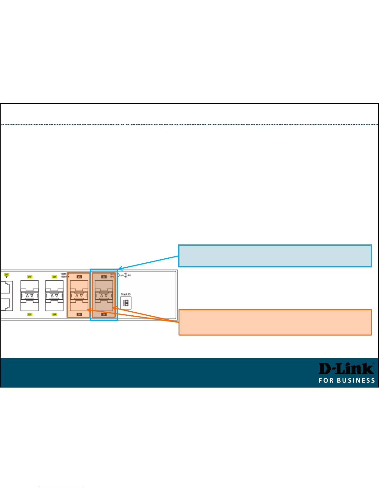
▪ With 2-port stacking the last two 10G ports 27 and 28 (or 51 and 52) are
used for stacking (in DGS-3630 series).
▪ Once stacking is enabled both ports 27 and 28 (or 51 and 52) are switched
into stacking (non-Ethernet) mode. Ports 25-26 (49-50) can still be used for
regular 10Gig Ethernet connectivity.
▪ With 4-port stacking enabled, all four 10G ports are dedicated to stacking and
cannot be used for regular 10Gig Ethernet connectivity.
27-28 are dedicated to Stacking when
2-port stacking is enabled (40 Gbps Stacking)
28
27
26
25
25-26 and 27-28 are dedicated to Stacking when
4-port stacking is enabled (80 Gbps Stacking)
Stacking: 2-port and 4-port stacking
DGS-3630-28TC
Page 3

Stacking Switches
Switch roles are assigned automatically during a Stack Election Stage.
You can influence the election results by manually assigning Stack Priorities.
Switch Roles in a Stack
Primary Master
(identified as H)
Leader of the stack.
Monitors and controls the
stack, assigns Stack IDs,
synchronises configurations.
Assigned to a switch with
-
lowest MAC
or
-
highest priority (lower priority
number, e.g. 1)
Backup Master
(identified as h)
Backup to the Primary Master.
Holds a copy of stack config,
monitors the Primary Master
and other switches.
Can be manually set by assigning
second highest priority after
Primary Master (e.g. 2)
Slave
Other switches in the stack.
Can take Backup Master and
Primary Master roles if those
are removed.
Default priority is 32
Page 4

Stacking Switches
Best practice when setting up a stack: configure Primary and Backup Masters with
higher priority (lower priority numbers), so that role selection does not only rely on
MAC addresses.
Hot Swapping in a Stack
Slave
The replacement Slave Switch will automatically accept
configuration pushed by the Primary Master switch.
Good practice is to set Stack Priority to 63 on the replacement
switch before connecting it to the stack.
Backup Master
Once a Backup Master switch is hot removed, a new Backup
Master is elected from existing Slave switches.
The new replacement switch can be hot swapped and elected
either as Slave or as Backup Master.
Primary Master
Once a Primary Master switch is hot removed, the Backup
Master becomes Primary Master, inheriting MAC and IP
addresses of the Primary Master.
A new Backup Master is elected from existing Slave switches.
Page 5

Stacking Switches (CLI)
▪ Before physically connecting the switches: Enable stacking and set one of the
switches with lower stacking priority number, so it becomes Stack Master.
Switch# stack
Switch# stack bandwidth 2
Switch# stack 1 priority 1
Switch# copy running-config startup-config
Switch# reboot
…
Switch# show stack
2/h
1/H
Switch# stack
Switch# stack bandwidth 2
Switch# copy running-config startup-config
Switch# reboot
Once stacked, the management of the switch stack can only be done through the
“Primary Master” switch.
Page 6

Stacking Switches (GUI)
▪ Make sure firmware version is the same in all switches.
▪ Management > Stacking > Physical Stacking.
▪ Set Stacking Mode to “Enabled”, click Apply.
▪ Set Priority to 1 (on Master), click Apply.
▪ Save Settings and reboot the switch.
▪ Enable Stacking on second switch. Save and reboot.
▪ Connect the switches via stacking ports. The Slave switch will reboot and will
show its new Stack ID.
MASTER
SWITCH
Slave switches can be left at default 32
Page 7

Stacking Switches (GUI) cont.
▪ When switches are stacked only the Master switch is accessible for management.
▪ Slave switches’ configuration is accessible through Master:
Page 8

Stacking Switches
▪ To remove the SFP+ Direct Attach cable – pull back on the cable release ring.
▪ To disable stacking:
Switch# no stack
Switch# copy running-config startup-config
 Loading...