

Page 1

CLI Reference Guide
Product Model: xStack
Layer 3 Managed Gigabit Ethernet Switch
Release 2.8
®
DGS-3600 Series
Page 2

TABLE OF CONTENTS
INTRODUCTION .................................................................................................................................................................... 1
USING THE CONSOLE CLI ................................................................................................................................................... 3
COMMAND SYNTAX ............................................................................................................................................................. 6
BASIC SWITCH COMMANDS ............................................................................................................................................... 8
BASIC IP COMMANDS ........................................................................................................................................................ 22
BPDU TUNNELING COMMANDS ....................................................................................................................................... 28
802.1X COMMANDS ............................................................................................................................................................ 31
ACCESS AUTHENTICATION CONTROL COMMANDS .................................................................................................... 52
ACCESS CONTROL LIST (ACL) COMMANDS .................................................................................................................. 73
ACL FLOW METERING COMMANDS ................................................................................................................................ 84
ADDRESS RESOLUTION PROTOCOL (ARP) COMMANDS ............................................................................................ 89
ARP SPOOFING PR EV EN TION COMMANDS ................................................................................................................... 93
BORDER GATEWAY PROTOCOL (BGP) DEBUG COMMANDS ..................................................................................... 95
BORDER GATEWAY PROTOCOL (BGP) COMMANDS ................................................................................................. 111
BPDU ATTACK PROTECTION COMMANDS .................................................................................................................. 156
CABLE DIAGNOSTICS COMMAND LIST ........................................................................................................................ 160
COMMAND HISTORY LIST ............................................................................................................................................... 162
COMMAND LOGGING COMMANDS ................................................................................................................................ 165
COMPOUND AUTHENTICATION COMMANDS ............................................................................................................... 167
CONFIGURATION COMMANDS ....................................................................................................................................... 174
COUNTER COMMANDS ................................................................................................................................................... 179
DEBUG COMMANDS ........................................................................................................................................................ 183
DHCP LOCAL RELAY COMMANDS ................................................................................................................................ 189
DHCP RELAY COMMANDS .............................................................................................................................................. 191
DHCP SERVER SCR EEN ING COMMANDS ..................................................................................................................... 201
DHCP SERVER COMMANDS ........................................................................................................................................... 205
DHCPV6 CLIENT COMMANDS ......................................................................................................................................... 220
DHCPV6 RELAY COMMANDS ......................................................................................................................................... 223
DHCPV6 SERVER COMMANDS ....................................................................................................................................... 229
D-LINK SINGLE IP MANAGEMENT COMMANDS ........................................................................................................... 241
D-LINK UNIDIRECTIONAL LINK DETECTION (DULD) COMMANDS ............................................................................ 252
DOMAIN NAME SERVER (DNS)RELAY COMMANDS .................................................................................................... 254
DOMAIN NAME SYSTEM (DNS) RESOLVER COMMANDS ........................................................................................... 258
DVMRP COMMANDS ........................................................................................................................................................ 263
ETHERNET RING PROTECTION SWITCHING (ERPS) COMMANDS ............................................................................ 268
FILTER DATABASE (FDB) COMMANDS ......................................................................................................................... 278
FLASH FILE SYSTEM (FFS) COMMANDS ...................................................................................................................... 285
GRATUITOUS ARP COMMANDS ..................................................................................................................................... 291
IEEE 802.1Q VLAN COMMANDS ..................................................................................................................................... 295
IEEE 802.1QINQ COMMANDS .......................................................................................................................................... 305
IGMP AND MLD SNOOPING COMMANDS ...................................................................................................................... 310
Page 3

INTERNET GROUP MANAGEMENT PROTOCOL (IGMP) COMMANDS ....................................................................... 329
IP DIRECTED BROADCAST COMMANDS ...................................................................................................................... 334
IP MULTICASTING COMMANDS...................................................................................................................................... 336
IP ROUTE FILTER COMMANDS ....................................................................................................................................... 338
IP-MAC-PORT BINDING (IMPB) COMMANDS ................................................................................................................ 349
IPV6 NEIGHBOR DISCOVER COMMANDS ..................................................................................................................... 365
IPV6 ROUTE COMMANDS ................................................................................................................................................ 371
IPV6 TUNNEL COMMANDS .............................................................................................................................................. 374
JAPANESE WEB-BASED ACCESS CONTROL (JWAC) COMMANDS ......................................................................... 380
JUMBO FRAME COMMANDS .......................................................................................................................................... 398
LIMITED IP MULTICAST ADDRESS COMMANDS .......................................................................................................... 400
LINK AGGREGATION COMMANDS................................................................................................................................. 407
LINK LAYER DISCOVERY PROTOCOL (LLDP) COMMANDS ....................................................................................... 412
LOOPBACK INTERFACE COMMANDS ........................................................................................................................... 428
LOOPBACK INTERFACE COMMANDS ........................................................................................................................... 432
MAC NOTIFICATION COMMANDS .................................................................................................................................. 435
MAC-BASED ACCESS CONTROL COMMANDS ............................................................................................................ 439
MESSAGE-DIGEST ALGORITHM 5 (MD5) COMMANDS ............................................................................................... 452
MIRROR COMMANDS ....................................................................................................................................................... 455
MSTP DEBUG ENHANCEMENT COMMANDS ................................................................................................................ 460
IGMP SNOOPING MULTICAST (ISM) VLAN COMMANDS ............................................................................................. 467
MULTIPLE SPANNING TREE PROTOCOL (MSTP) COMMANDS ................................................................................. 472
NETWORK LOAD BALANCING (NLB) COMMANDS ...................................................................................................... 483
OPEN SHORTEST P ATH FIRST (OSPFV3) COMMANDS .............................................................................................. 486
OSPF COMMANDS ........................................................................................................................................................... 500
OSPF DEBUG ENHANCEMENT COMMANDS ................................................................................................................ 517
PASSWORD ENCRYPTION COMMANDS ....................................................................................................................... 534
PING COMMANDS ............................................................................................................................................................ 538
POLICY ROUTE COMMANDS .......................................................................................................................................... 542
PORT SECURITY COMMANDS ........................................................................................................................................ 545
PROTOCOL INDEPENDENT MULTICAST (PIM) COMMANDS ...................................................................................... 548
PROTOCOL VLAN GROUP COMMANDS ........................................................................................................................ 564
QUALITY OF SERVICE (QOS) COMMANDS ................................................................................................................... 569
REMOTE COPY PROTOCOL (RCP) COMMANDS .......................................................................................................... 582
REMOTE SWITCHED PORT ANALYZER (RSPAN) COMMANDS .................................................................................. 593
RIPNG COMMANDS .......................................................................................................................................................... 599
ROUTING INFORMATION PROTOCOL (RIP) COMMANDS ........................................................................................... 604
SAFEGUARD ENGINE COMMANDS ............................................................................................................................... 607
SECURE SHELL (SSH) COMMANDS .............................................................................................................................. 610
SECURE SOCKETS LAYER (SSL) COMMANDS ............................................................................................................ 616
SFLOW COMMANDS ........................................................................................................................................................ 621
SIMPLE NETWORK MANAGEMENT PROTOCOL (SNMP) COMMANDS ..................................................................... 630
Page 4

STACKING COMMANDS .................................................................................................................................................. 643
STATIC MAC-BASED VLAN COMMANDS ...................................................................................................................... 648
STATIC MULTICAST ROUTE COMMANDS ..................................................................................................................... 650
SUBNET VLAN COMMANDS ............................................................................................................................................ 652
SUPER VLAN COMMANDS .............................................................................................................................................. 656
SWITCH PORT COMMANDS ............................................................................................................................................ 660
SYSLOG OR TRAP SOURCE-INTERFACE COMMANDS .............................................................................................. 666
SYSTEM LOG COMMANDS .............................................................................................................................................. 669
TECHNICAL SUPPORT COMMANDS .............................................................................................................................. 680
TELNET CLIENT COMMANDS ......................................................................................................................................... 683
TFTP CLIENT COMMANDS .............................................................................................................................................. 684
TIME AND SNTP COMMANDS ......................................................................................................................................... 689
TIME RANGE COMMANDS ............................................................................................................................................... 695
TRACE ROUTE COMMANDS ........................................................................................................................................... 697
TRAFFIC CONTROL COMMANDS ................................................................................................................................... 700
TRAFFIC SEGMENTATION COMMANDS ........................................................................................................................ 704
TRUSTED HOST COMMANDS ......................................................................................................................................... 706
UNICAST ROUTE COMMANDS ........................................................................................................................................ 708
UTILIZATION COMMANDS ............................................................................................................................................... 722
VLAN TRUNKING COMMANDS ....................................................................................................................................... 725
VRRP DEBUG COMMANDS ............................................................................................................................................. 728
VRRP COMMANDS ........................................................................................................................................................... 734
WEB-BASED ACCESS CONTROL (WAC) COMMANDS ................................................................................................ 740
PASSWORD RECOVERY COMMANDS ........................................................................................................................... 750
TECHNICAL SPECIFICATIONS ........................................................................................................................................ 751
Page 5
xStack® DGS-3600 Series Layer 3 Gigabit Ether net Manag ed Sw itc h CLI Manu al
DGS-3627 Gigabit Ethernet Switch
1
INTRODUCTION
The Switch can be managed through the Switch’s serial port, Telnet, or the Web-based management agent. The
Command Line Interface (CLI) can be used to configure and manage the Switch via the serial port or Telnet interfaces.
The DGS-3600 Layer 3 stackable Gigabit Ethernet switch series are members of the D-Link xStack® family. Ranging
from 10/100Mbps edge switches to core gigabit switches, the xStack® switch family has been future-proof designed to
provide a stacking architecture with fault tolerance, flexibility, port density, robust security and maximum throughput with
a user-friendly management interface for the networking professional.
This manual provides a reference for all of the commands contained in the CLI for the xStack® DGS-3612, DGS-3612G,
DGS-3627, DGS-3627G, DGS-3627, DGS-3627G and DGS-3650 series of switches. Configuration and management of
the Switch via the Web-based management agent is discussed in the User’s Guide.
NOTE: For the remainder of this manual, all versions of the DGS-3612, DGS-3612G, DGS-3627, DGS3627G, DGS-3627, DGS-3627G and DGS-3650 switches will be referred to as simply the Switch or the
DGS-3627.
Accessing the Switch via the Serial Port
The Switch’s serial port’s default settings are as follows:
1. 115200 baud
2. no parity
3. 8 data bits
4. 1 stop bit
A computer running a terminal emulation program capable of emulating a VT-100 terminal and a serial port configured as
above is then connected to the Switch’s serial port via an RS-232 DB-9 cable.
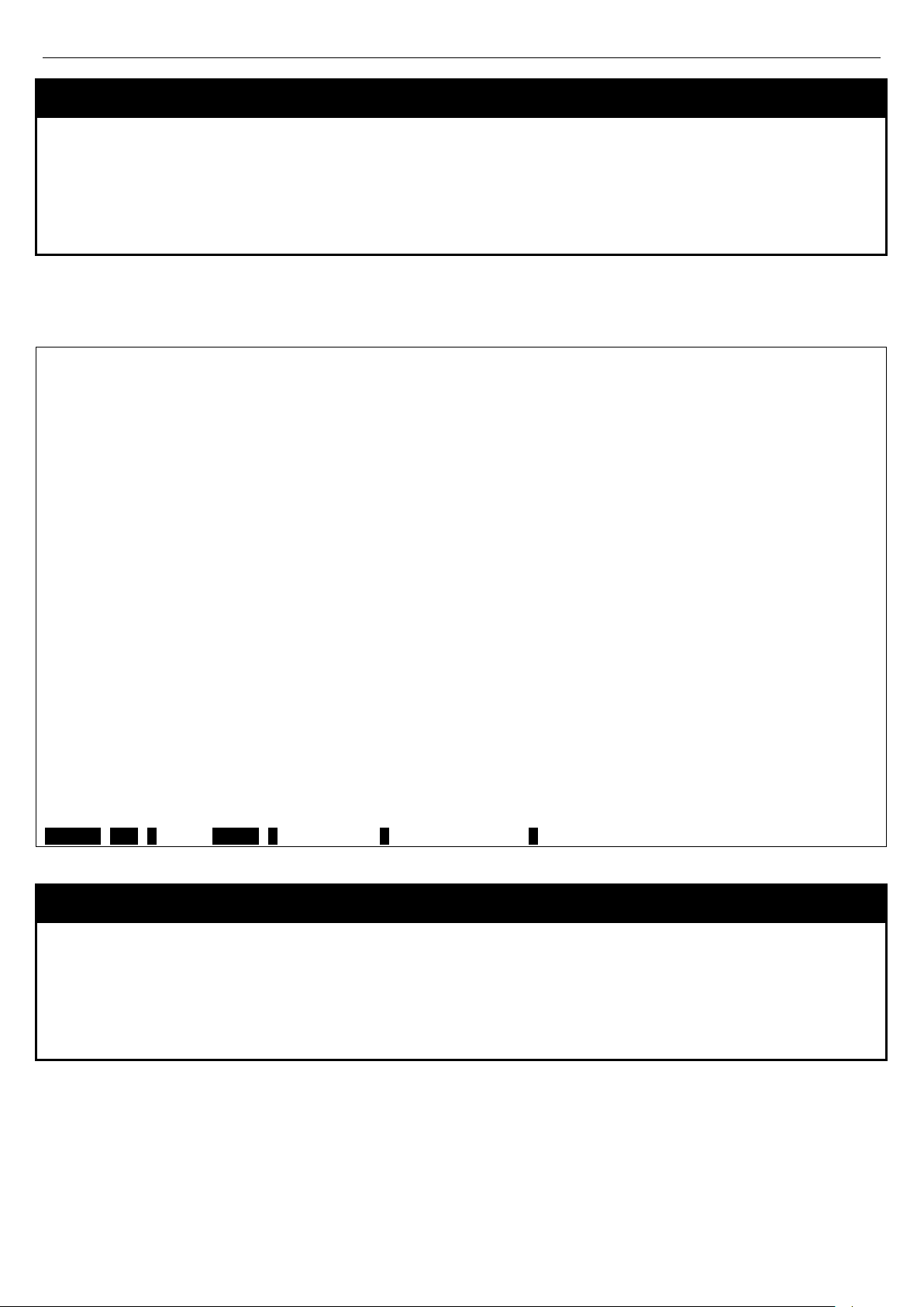
With the serial port properly connected to a management computer, the following screen should be visible. If this screen
does not appear, try pressing Ctrl+r o refresh the console screen.
Command Line Interface
Firmware: Build 2.80.B31
Copyright(C) 2010 D-Link Corporation. All rights reserved.
UserName:
Figure 1-1. Initial CLI screen
There is no initial username or password. Just press the Enter key twice to display the CLI input cursor −DGS3627:admin# . This is the command line where all commands are input.
Setting the Switch’s IP Address
Each Switch must be assigned its own IP Address, which is used for communication with an SNMP network manager or
other TCP/IP application (for example BOOTP, TFTP). The Switch’s default IP address is 10.90.90.90. You can change
the default Switch IP address to meet the specification of your networking address scheme.
1
Page 6
xStack® DGS-3600 Series Layer 3 Gigabit Ether net Manag ed Sw itc h CLI Manu al
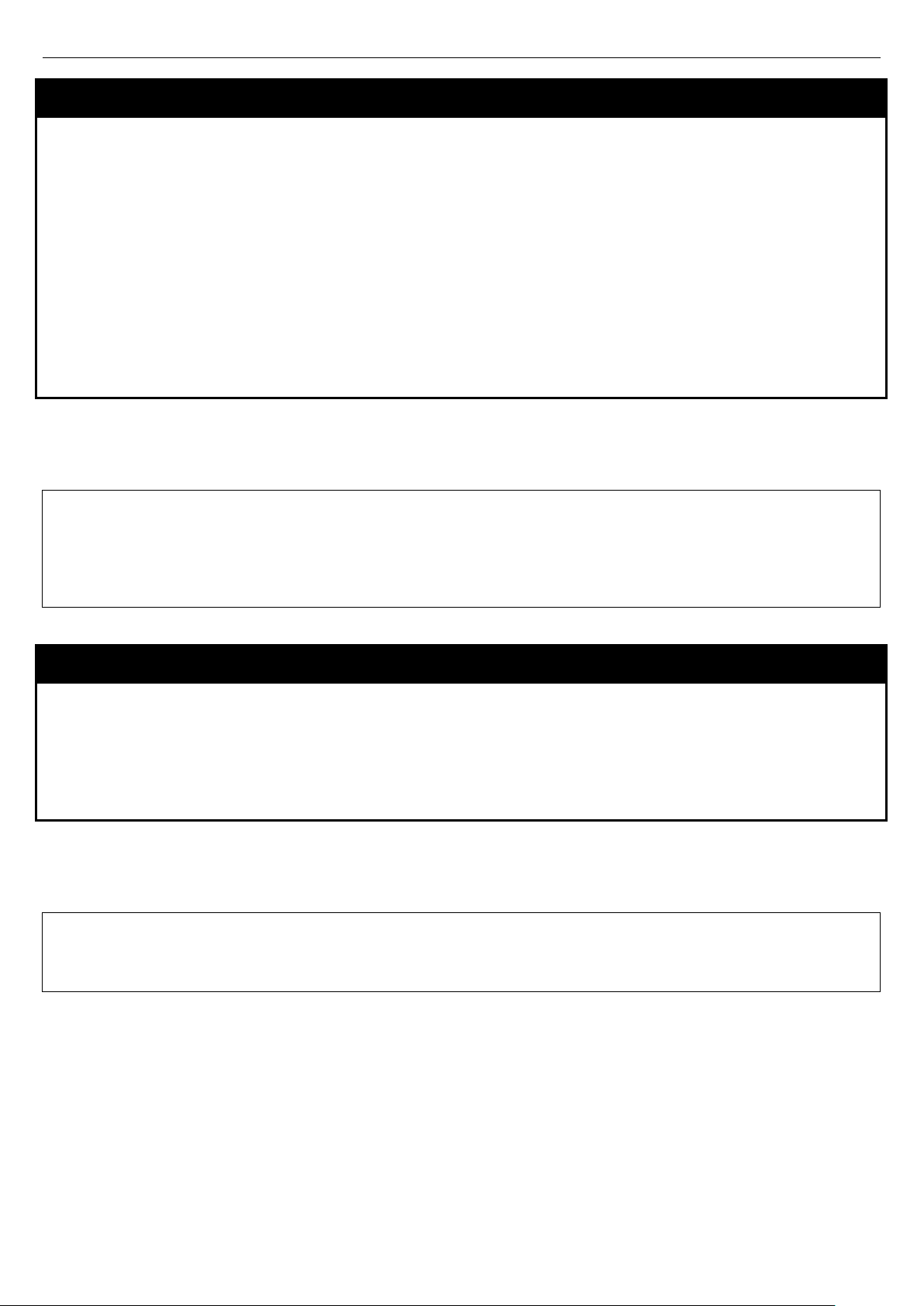
The Switch is also assigned a unique MAC address by the factory. This MAC address cannot be changed, and can be
found on the initial boot console screen – shown below.
Boot Procedure 1.10-B09
-----------------------------------------------------------------------------
Power On Self Test ...................................... 100 %
MAC Address : 00-19-5B-F5-26-C0
H/W Version : 1A1G
Please wait, loading V2.80.B31 Runtime image ............ 100 %
UART init ............................................... 100 %
Device Discovery ........................................ -
Figure 1-2. Boot screen
The Switch’s MAC address can also be found in the Web management program on the Switch Information (Basic
Settings) window in the Configuration menu.
The IP address for the Switch must be set before it can be managed with the Web-based manager. The Switch IP
address can be automatically set using BOOTP or DHCP protocols, in which case the actual address assigned to the
Switch must be known.
The IP address may be set using the Command Line Interface (CLI) over the console serial port as follows:
1. Starting at the command line prompt, enter the commands config ipif System ipaddress
xxx.xxx.xxx.xxx/yyy.yyy.yyy.yyy. Where the x’s represent the IP address to be assigned to the IP interface
named System and the y’s represent the corresponding subnet mask.
2. Alternatively, you can enter config ipif System ipaddress xxx.xxx.xxx.xxx/z. Where the x’s represent the IP
address to be assigned to the IP interface named System and the z represents the corresponding number of
subnets in CIDR notation.
The IP interface named System on the Switch can be assigned an IP address and subnet mask which can then be used
to connect a management station to the Switch’s Telnet or Web-based management agent.
DGS-3627:admin# config ipif System ipaddress 10.24.22.200/255.0.0.0
Command: config ipif System ipaddress 10.24.22.200/8
Success.
DGS-3627:admin#
Figure 1-3. Assigning an IP Address
In the above example, the Switch was assigned an IP address of 10.24.22.200 with a subnet mask of 255.0.0.0. The
system message Success indicates that the command was executed successfully. The Switch can now be configured
and managed via Telnet, SNMP MIB browser and the CLI or via the Web-based management agent using the above IP
address to connect to the Switch.
2
Page 7

xStack® DGS-3600 Series Layer 3 Gigabit Ether net Manag ed Sw itc h CLI Manu al
DGS-3627:admin# _
2
USING THE CONSOLE CLI
The Switch supports a console management interface that allows the user to connect to the Switch’s management agent
via a serial port and a terminal or a computer running a terminal emulation program. The console can also be used over
the network using the TCP/IP Telnet protocol. The console program can be used to configure the Switch to use SNMPbased network management software over the network.
This chapter describes how to use the console interface to access the Switch, change its settings, and monitor its
operation.
NOTE: Switch configuration settings are saved to non-volatile RAM using the save command. The current
configuration will then be retained in the Switch’s NV-RAM, and reloaded when the Switch is rebooted. If
the Switch is rebooted without using the save command, the last configuration saved to NV-RAM will be
loaded.
Connecting to the Switch
The console interface is used by connecting the Switch to a VT100-compatible terminal or a computer running an
ordinary terminal emulator program (e.g., the HyperTerminal program included with the Windows operating system)
using an RS-232C serial cable. Your terminal parameters will need to be set to:
• VT-100 compatible
• 115200 baud
• 8 data bits
• No parity
• One stop bit
• No flow control
Users can also access the same functions over a Telnet interface. Once an IP address has been set for the Switch, users
can use a Telnet program (in VT-100 compatible terminal mode) to access and control the Switch. All of the screens are
identical, whether accessed from the console port or from a Telnet interface.
After the Switch reboots and you have logged in, the console looks like this:
DGS-3627 Gigabit Ethernet Switch
Command Line Interface
Firmware: Build 2.80.B31
Copyright(C) 2010 D-Link Corporation. All rights reserved.
UserName:
PassWord:
Figure 2- 1. Initial Console Screen after logging in
Commands are entered at the command prompt, DGS-3627:admin# .
There are a number of helpful features included in the CLI. Entering the ? command will display a list of all of the top-
level commands.
3
Page 8
xStack® DGS-3600 Series Layer 3 Gigabit Ether net Manag ed Sw itc h CLI Manu al
CTRL+C ESC q Quit SPACE n Next Page Enter Next Entry a All
DGS-3627:admin#
DGS-3627:admin# config account
DGS-3627:admin# ?
Command: ?
..
?
cable_diag ports
cd
clear
clear address_binding dhcp_snoop binding_entry ports
clear address_binding nd_snoop binding_entry ports
clear arptable
clear attack_log
clear bgp
clear bgp dampening
clear bgp flap_statistics
clear counters
clear dhcp_binding
clear dhcpv6 binding
clear fdb
clear ip prefix_list counter
clear jwac auth_state
clear log
clear mac_based_access_control auth_state
clear port_security_entry port
clear wac auth_state
Figure 2- 2. The ? Command
When users enter a command without its required parameters, the CLI will prompt a Next possible completions:
message.
DGS-3627:admin# config account
Command: config account
Next possible completions:
<username>
Figure 2- 3. Example Command Parameter Help
In this case, the command config account was entered with the parameter <username>. The CLI will then prompt to
enter the <username> with the message, Next possible completions:. Every command in the CLI has this feature, and
complex commands have several layers of parameter prompting.
In addition, after typing any given command plus one space, all of the next possible sub-commands can be seen, in
sequential order, by repeatedly pressing the Tab key.
To re-enter the previous command at the command prompt, press the up arrow cursor key. The previous command will
appear at the command prompt.
DGS-3627:admin# config account
Command: config account
Next possible completions:
<username>
Figure 2- 4. Using the Up Arrow to Re-enter a Command
4
Page 9

xStack® DGS-3600 Series Layer 3 Gigabit Ether net Manag ed Sw itc h CLI Manu al
DGS-3627:admin#
DGS-3627:admin#
In the above example, the command config account was entered without the required parameter <username>, the CLI
returned the Next possible completions: <username> prompt. The up arrow cursor control key was pressed to reenter the previous command (config account) at the command prompt. Now the appropriate username can be entered
and the config account command re-executed.
All commands in the CLI function in this way. In addition, the syntax of the help prompts are the same as presented in this
manual − angle brackets < > indicate a numerical value or character string, braces { } indicate optional parameters or a
choice of parameters, and brackets [ ] indicate required parameters.
If a command is entered that is unrecognized by the CLI, the top-level commands will be displayed under the Available
commands: prompt.
DGS-3627:admin# the
Available commands:
.. ? cable_diag cd
clear config copy create
debug delete dir disable
download enable erase login
logout no ping ping6
reboot reconfig rename reset
save show telnet traceroute
traceroute6 upload
Figure 2- 5. Available Commands
The top-level commands consist of commands such as show or config. Most of these commands require one or more
parameters to narrow the top-level command. This is equivalent to show what? or config what? Where the what? is the
next parameter.
For example, if you enter the create command with no additional parameters, the CLI will then display all of the possible
next parameters.
DGS-3627:admin# create
Command: create
Next possible completions:
802.1x access_profile account address_binding
arpentry authen authen_enable authen_login
authentication bgp cpu dhcp
dhcpv6 dot1v_protocol_group double_vlan
erps fdb host_name igmp_snooping
ip ip_tunnel ipif ipmroute
iproute ipv6 ipv6route jwac
link_aggregation loopback mac_based_access_control
mac_based_access_control_local mac_based_vlan md5
mirror multicast_fdb multicast_range nlb
ospf ospfv3 pim policy_route
route route_map rspan sflow
snmp stp subnet_vlan super_vlan
syslog trusted_host vlan vlan_translation
vrrp wac
Figure 2- 6. Next possible completion s: Create command
In the above example, all of the possible next parameters for the create command are displayed.
5
Page 10

xStack® DGS-3600 Series Layer 3 Gigabit Ether net Manag ed Sw itc h CLI Manu al
3
COMMAND SYNTAX
The following symbols are used to describe how command entries are made and values and arguments are specified in
this manual. The online help contained in the CLI and available through the console interface uses the same syntax.
NOTE: All commands are case-sensitive. Be sure to disable Caps Lock or any other unwanted
function that changes text case.
<angle brackets>
Purpose Encloses a variable or value that must be specified.
Syntax
Description In the above syntax example, users must supply an IP interface name in the <ipif_name>
create ipif <ipif_name 12> <network_address> (<ip_addr/netmask>) <vlan_name 32>
{secondary | state [enable | disable]}
space, a VLAN name in the <vlan_name 32> space, and the network address, including the
netmask, in the <network_address> (<ip_addr/netmask>) space. Do not type the angle
brackets.
Example Command
create ipif Engineering 10.24.22.5/255.0.0.0 Design
[square brackets]
Purpose Encloses a required value or set of required arguments. One value or argument can be
specified.
Syntax
Description
Example Command
create account [admin | operator | user] <username 15>
In the above syntax example, users must specify the admin, operator, or user level account to
be created. Do not type the square brackets.
create account admin ctsnow
| vertical bar
Purpose Separates two or more mutually exclusive items in a list, one of which must be entered.
Syntax
Description
Example Command
create account [admin | operator |user] <username 15>
In the above syntax example, you must specify the admin, operator, or user level account to
be created. Do not type the backslash.
create account admin ctsnow
{braces}
Purpose Encloses an optional value or set of optional arguments.
6
Page 11
{braces}
xStack® DGS-3600 Series Layer 3 Gigabit Ether net Manag ed Sw itc h CLI Manu al
Syntax
Description
Example command
reset {[config | system]}
In the above syntax example, users have the option to specify config or system. It is not
necessary to specify either optional value, however the effect of the system reset is dependent
on which, if any, value is specified. Therefore, with this example there are three possible
outcomes of performing a system reset. See the following chapter, Basic Commands for more
details about the reset command.
reset config
Line Editing Key Usage
Delete Deletes the character under the cursor and then shifts the remaining characters in the line to the
left.
Backspace Deletes the character to the left of the cursor and then shifts the remaining characters in the line
to the left.
Left Arrow Moves the cursor to the left.
Right Arrow Moves the cursor to the right.
Up Arrow Repeats the previously entered command. Each time the up arrow is pressed, the command
previous to that displayed appears. This way it is possible to review the command history for the
current session. Use the down arrow to progress sequentially forward through the command
history list.
Down Arrow The down arrow will display the next command in the command history entered in the current
session. This displays each command sequentially as it was entered. Use the up arrow to
review previous commands.
Tab Shifts the cursor to the next field to the left.
Multiple Page Displa y Control Keys
Space Displays the next page.
CTRL+c Stops the display of remaining pages when multiple pages are to be displayed.
ESC Stops the display of remaining pages when multiple pages are to be displayed.
n Displays the next page.
p Displays the previous page.
q Stops the display of remaining pages when multiple pages are to be displayed.
r Refreshes the pages currently displayed.
a Displays the remaining pages without pausing between pages.
Enter Displays the next line or table entry.
7
Page 12

xStack® DGS-3600 Series Layer 3 Gigabit Ether net Manag ed Sw itc h CLI Manu al
4
BASIC SWITCH COMMANDS
The basic switch commands in the Command Line Interface (CLI) are listed (with the appropriate parameters) in the
following table.
Command Parameters
create account [admin | operator | user] <usernam e 15>
config account <username> {encrypt [plain_text| sha_1] <password>}
show account
delete account <username> {<string>}
show session
show switch
show serial_port
config serial_port {baud_rate [9600 | 19200 | 38400 | 115200] auto _l ogo ut [nev er | 2_m inutes |
5_minutes | 10_minutes | 15_minutes]}
enable clipaging
disable clipaging
enable telnet {<tcp_port_number 1-65535>}
disable telnet
telnet [<ipaddr> | <domain_nam e 255>] {tcp_ port <v alue 0-65535>}
enable web {<tcp_port_number 1-65535>}
disable web
save {[config {<drive_id>} <pathname 64> | log | all]}
reboot {<string>}
reset {[config |system]} {<string>}
login
logout
show device_status
config command_prompt [<string 16> | username | default]
config greeting_message {default}
show greeting_message
Each command is listed, in detail, in the following sections.
8
Page 13

xStack® DGS-3600 Series Layer 3 Gigabit Ether net Manag ed Sw itc h CLI Manu al
DGS-3627:admin# create account admin dlink
DGS-3627:admin#
DGS-3627:admin# create account operator frazier
DGS-3627:admin#
DGS-3627:admin# create account user reed
DGS-3627:admin#
create account
Purpose Used to create user accounts.
Syntax
Description
Parameters
Restrictions Only Administrator-level users can issue this command.
Example usage:
To create an administrator-level user account with the username “dlink”.
Command: create account admin dlink
Enter a case-sensitive new password:****
Enter the new password again for confirmation:****
Success.
create account [admin | operator | user] <username 15>
The create account command is used to create user accounts that consist of a username of 1 to
15 characters and a password of 0 to 15 characters. Up to eight user accounts can be created.
admin <username 15> – Enter a name between 1 and 15 alphanumeric characters to define the
administrator account created here.
operator <username 15> – Enter a name between 1 and 15 alphanumeric characters to define the
operator account created here.
user <username 15> – Enter a name between 1 and 15 alphanumeric characters to define the
user account created here.
To create an operator-level user account with the username “frazier”.
Command: create account operator frazier
Enter a case-sensitive new password:****
Enter the new password again for confirmation:****
Success.
To create a user-leve l user acc ount w ith the user name “reed”.
Command: create account user reed
Enter a case-sensitive new password:****
Enter the new password again for confirmation:****
Success.
9
Page 14

xStack® DGS-3600 Series Layer 3 Gigabit Ether net Manag ed Sw itc h CLI Manu al
DGS-3627:admin# config account dlink
DGS-3627:admin#
DGS-3627:admin# show account
config account
Purpose Used to configure user accounts.
Syntax
Description
Parameters
Restrictions Only Administrator-level users can issue this command.
Example usage:
To configure the user password of “dlink” account:
Command: config account dlink
Enter a old password:****
Enter a case-sensitive new password:****
Enter the new password again for confirmation:****
Success.
config account <username> {encrypt [plain_text| sha_1] <password>}
The config account command configures a user account that has been created using the
create account command.
<username> – Enter a name between 1 and 15 alphanumeric characters to define the
administrator account to configure here.
encrypt - Select the encrypted form of password.
plain_text - Passwords sho uld be bet ween 0 and 15 c harac ter s.
sha_1 - Passwords should be fixed to 35 bytes long.
<password> - The password for the user account.
show account
Purpose Used to display user accounts
Syntax
Description Displays all user accounts created on the Switch. Up to eight user accounts can exist at one
Parameters None.
Restrictions Only Administrator-level users can issue this command.
Example usage:
To display the accounts that have been created:
Command: show account
Current Accounts:
Username Access Level
--------------- -----------dlink Admin
DGS-3627:admin#
show account
time.
10
Page 15

xStack® DGS-3600 Series Layer 3 Gigabit Ether net Manag ed Sw itc h CLI Manu al
DGS-3627:admin# delete account System
DGS-3627:admin#
DGS-3627:admin# show session
CTRL+C ESC q Quit SPACE n Next Page p Previous Page r Refresh
delete account
Purpose Used to delete an existing user account.
Syntax
Description
Parameters
Restrictions O nl y Adminis trat or -level users can issue this command.
Example usage:
To delete the user account “System”:
Command: delete account System
Are you sure to delete the last administrator account?(y/n)y
Success.
delete account <username> {<string>}
The delete account command deletes a user account that has been created using the
create account command.
<username>
<string> – Enter an alphanumeric string of up to 15 characters to define the username.
show session
Purpose Used to display a list of currently logged-in users.
Syntax
Description This command displays a list of all the users that are logged-in at the time the command is
Parameters None
Restrictions None.
Example usage:
To display the way that the users logged in:
Command: show session
ID Live Time From Level Name
-- --------- ------------ ----- ----------8 03:36:27 Serial Port 5 Anonymous
Total Entries: 1
show session
issued.
11
Page 16
xStack® DGS-3600 Series Layer 3 Gigabit Ether net Manag ed Sw itc h CLI Manu al
DGS-3627:admin# show switch
CTRL+C ESC q Quit SPACE n Next Page p Previous Page r Refresh
show switch
Purpose Used to display general information about the Switch.
Syntax
Description This command displays information about the Switch.
Parameters None.
Restrictions None.
Example usage:
To display the Switch’s information:
Command: show switch
Device Type : DGS-3627 Gigabit Ethernet Switch
MAC Address : 00-1C-F0-B5-40-00
IP Address : 10.24.73.21 (Manual)
VLAN Name : default
Subnet Mask : 255.0.0.0
Default Gateway : 0.0.0.0
Boot PROM Version : Build 1.10-B09
Firmware Version : Build 2.80.B31
Hardware Version : A1
Serial Number : P4F7191000001
System Name :
System Location :
System Contact :
Spanning Tree : Disabled
GVRP : Disabled
IGMP Snooping : Disabled
MLD Snooping : Disabled
RIP : Disabled
DVMRP : Disabled
PIM : Disabled
OSPF : Disabled
TELNET : Enabled (TCP 23)
show switch
show serial_port
Purpose Used to display the current serial port settings.
Syntax
Description This command displays the current serial port settings.
Parameters None.
Restrictions None
Example usage:
To display the serial port setting:
show serial_port
12
Page 17

xStack® DGS-3600 Series Layer 3 Gigabit Ether net Manag ed Sw itc h CLI Manu al
DGS-3627:admin# show serial_port
DGS-3627:admin#
DGS-3627:admin# config serial_port baud_rate 115200
DGS-3627:admin#
Command: show serial_port
Baud Rate : 115200
Data Bits : 8
Parity Bits : None
Stop Bits : 1
Auto-Logout : 10 mins
config serial_port
Purpose Used to configure the serial port.
Syntax
Description
Parameters
Restrictions
Example usage:
To configure baud rate:
Command: config serial_port baud_rate 115200
Success.
config serial_port {baud_rate [9600 | 19200 | 38400 | 115200] | auto_logout [never | 2_minutes |
5_minutes | 10_minutes | 15_minutes]}
This command is used to configure the serial port’s baud rate and auto logout settings.
baud_rate [9600 | 19200 | 38400 | 115200] − The serial bit rate that will be used to communicate with
the management host. There are four options: 9600, 19200, 38400, and 115200.
never − No time limit on the length of time the console can be open with no user input.
2_minutes − The console will log out the current user if there is no user input for 2 minutes.
5_minutes − The console will log out the current user if there is no user input for 5 minutes.
10_minutes − The console will log out the current user if there is no user input for 10 minutes.
15_minutes − The console will log out the current user if there is no user input for 15 minutes.
Only Administrator and Operator-level users can issue this command.
enable clipaging
Purpose Used to pause the scrolling of the console screen when the show command displays more
than one page.
Syntax
Description This command is used when issuing the show command which causes the console screen to
Parameters None.
Restrictions Only Administrator and Operator-level users can issue this command.
Example usage:
To enable pausing of the screen display when the show command output reaches the end of the page:
enable clipaging
rapidly scroll through several pages. This command will cause the console to pause at the
end of each page. The default setting is enabled.
13
Page 18

xStack® DGS-3600 Series Layer 3 Gigabit Ether net Manag ed Sw itc h CLI Manu al
DGS-3627:admin# enable clipaging
DGS-3627:admin#
DGS-3627:admin# disable clipaging
DGS-3627:admin#
DGS-3627:admin# enable telnet 23
DGS-3627:admin#
Command: enable clipaging
Success.
disable clipaging
Purpose Used to disable the pausing of the console screen scrolling at the end of each page when the
show command displays more than one screen of information.
Syntax
Description This command is used to disable the pausing of the console screen at the end of each page
Parameters None.
Restrictions Only Administrator and Operator-level users can issue this command.
Example usage:
To disable pausing of the screen display when show command output reaches the end of the page:
Command: disable clipaging
Success.
disable clipaging
when the show command would display more than one screen of information.
enable telnet
Purpose Used to enable communication with and management of the Switch using the Telnet
protocol.
Syntax
Description This command is used to enable the Telnet protocol on the Switch. The user can specify the
Parameters
Restrictions Only Administrator and Operator-level users can issue this command.
Example usage:
To enable Telnet and configure port number:
Command: enable telnet 23
Success.
enable telnet {<tcp_port_number 1-65535>}
TCP or UDP port number the Switch will use to listen for Telnet requests.
{<tcp_port_number 1-65535>} − The TCP port number. TCP ports are numbered between 1
and 65535. The “well-known” TCP port for the Telnet protocol is 23.
14
Page 19

xStack® DGS-3600 Series Layer 3 Gigabit Ether net Manag ed Sw itc h CLI Manu al
DGS-3627:admin# disable telnet
DGS-3627:admin#
DGS-3627:admin# telnet 10.0.0.8
DGS-3627:admin#
disable telnet
Purpose Used to disable the Telnet protocol on the Switch.
Syntax
Description This command is used to disable the Telnet protocol on the Switch.
Parameters None.
Restrictions Only Administrator and Operator-level users can issue this command.
Example usage:
To disable the Telnet protocol on the Switch:
Command: disable telnet
Success.
disable telnet
telnet
Purpose Used to login remote system with telnet protocol.
Syntax
telnet [<ipaddr> | <domain_name 255>] {tcp_port <value 0-65535>}
Description This command is used to login remote system with Telnet protocol on the Switch.
Parameters
Restrictions Only Administrator and Operator-level users can issue this command.
Example usage:
To login to the remote system using telnet on the Switch:
Command: telnet 10.0.0.8
Success.
<ipaddr> – Specify the IP address of telnet server system
<domain_name 255> - Specify the domain name used.
tcp_port – The TCP port number. TCP ports are numbered between 1 and 65535. The “
well-known” TCP port for the Telnet protocol is 23.
15
Page 20

xStack® DGS-3600 Series Layer 3 Gigabit Ether net Manag ed Sw itc h CLI Manu al
DGS-3627:admin# enable web 80
DGS-3627:admin#
DGS-3627:admin# disable web
DGS-3627:admin#
enable web
Purpose Used to enable the HTTP-based management software on the Switch.
Syntax
Description This command is used to enable the Web-based management software on the Switch. The
Parameters
Restrictions Only Administrator and Operator-level users can issue this command.
Example usage:
To enable HTTP and configure port number:
Command: enable web 80
Note: SSL will be disabled if web is enabled.
Success.
enable web {<tcp_port_number 1-65535>}
user can specify the TCP port number the Switch will use to listen for Telnet requests.
{<tcp_port_number 1-65535>} − The TCP port number. TCP ports are numbered between 1
and 65535. The “well-known” port for the Web-based management software is 80.
disable web
Purpose Used to disable the HTTP-based management software on the Switch.
Syntax
Description This command disables the Web-based management software on the Switch.
Parameters None.
Restrictions Only Administrator and Operator-level users can issue this command.
Example usage:
To disable HTTP:
Command: disable web
Success.
disable web
16
Page 21
xStack® DGS-3600 Series Layer 3 Gigabit Ether net Manag ed Sw itc h CLI Manu al
DGS-3627:admin# save
DGS-3627:admin#
DGS-3627:admin# reboot
Please wait, the switch is rebooting...
save
Purpose Used to save changes in the Switch’s configuration to non-vol ati le RA M.
Syntax
Description This command is used to enter the current switch configuration or log file into non-volatile
Parameters
Restrictions Only Administrator and Operator-level users can issue this command.
Example usage:
To save the Switch’s current configuration to non-volatile RAM:
Command: save
Saving all configurations to NV-RAM... Done.
save {[config {<drive_id>} < pathname 64> | log | all]}
RAM. The saved switch configuration will be loaded into the Switch’s memory each time the
Switch is restarted.
config <drive_id> – Specify to save current settings to the Flash memory of the switch.
<drive_id> – Specify the ID of the drive where the log or configuration file will be placed.
<pathname 64> – Enter a name of up to 64 characters to define the file to be saved on the
flash drive.
log – Specify to save current Switch log to NV-RAM.
all – Use to save the configuration and log file to NV-RAM.
reboot
Purpose Used to restart the Switch.
Syntax
Description This command is used to restart the Switch.
Parameters None.
Restrictions Only Administrator-level users can issue this command.
Example usage:
To restart the Switch:
Command: reboot
Are you sure want to proceed with the system reboot? (y|n) y
reboot {<string>}
17
Page 22

xStack® DGS-3600 Series Layer 3 Gigabit Ether net Manag ed Sw itc h CLI Manu al
DGS-3627:admin# reset config
DGS-3627:admin#
DGS-3627:admin# login
UserName:
reset
Purpose Used to reset the Switch to the factory default settings.
Syntax
Description This command is used to restore the Switch’s configuration to the default settings assigned
Parameters
Restrictions Only Administrator-level users can issue this command.
Example usage:
To restore all of the Switch’s parameters to its default values:
Command: reset config
Are you sure to proceed with system reset?(y/n) y
Success.
reset {[config |system]} {<string>}
from the factory.
config − If the keyword ‘config’ is specified, all of the factory default settings are restored on
the Switch including the IP address, user accounts, and the switch history log. The Switch will
not save or reboot.
system − If the keyword ‘system’ is specified all of the factory default settings are restored on
the Switch. The Switch will save and reboot after the settings are changed to default.
Rebooting will clear all entries in the Forwarding Data Base.
If no parameter is specified, the Switch’s current IP address, user accounts, and the switch
history log are not changed. All other parameters are restored to the factory default settings.
The Switch will not save or reboot.
login
Purpose Used to log in a user to the Switch’s console.
Syntax
Description This command is used to initiate the login procedure. The user will be prompted for a
Parameters None.
Restrictions None.
Example usage:
To initiate the login procedure:
Command: login
login
Username and Password.
18
Page 23

xStack® DGS-3600 Series Layer 3 Gigabit Ether net Manag ed Sw itc h CLI Manu al
DGS-3627:admin# logout
DGS-3627:admin# show device_status
CTRL+C ESC q Quit SPACE n Next Page p Previous Page r Refresh
a string of 16 alphanumerical characters with no spaces, or the user may enter the current login
logout
Purpose Used to log out a user from the Switch’s console.
Syntax
Description This command terminates the current user’s session on the Switch’s console.
Parameters None.
Restrictions None.
Example usage:
To terminate the current user’s console session:
logout
show device_status
Purpose Used to display the current status of the hardware of the Switch.
Syntax
Description This command displays the current status of the power and fans on the system. In the fan
show device_status
status display there are fans on the left of the switch, on the right, at the back and a CPU fan,
if the fans are working normally the display will read “OK” in the fan field. If any of the fans fail
the corresponding field will read ‘Fail’.
Parameters None.
Restrictions None.
Example usage:
To show the device status of the Switch:
Command: show device_status
Unit 1:
Internal Power: Active
External Power: Fail
Left Fan : OK
Right Fan : OK
Back Fan : OK
CPU Fan : OK
config command_prompt
Purpose Used to configure the command prompt for the Command Line Interface.
Syntax
Description This command is used to configure the command prompt for the CLI interface of the Switch. The
config command_prompt [<strin g 16> | username | default]
current command prompt consists of “product name + : + user level + product name” (ex. DGS3627:admin# ). The user may replace all parts of the command prompt, except the # by entering
19
Page 24

xStack® DGS-3600 Series Layer 3 Gigabit Ether net Manag ed Sw itc h CLI Manu al
DGS-3627:admin# config command_prompt Tiberius
Tiberius:admin#
username configured on the Switch.
Parameters
Restrictions
Example usage:
To configure the command prompt:
Command: config command_prompt Tiberius
Success.
<string 16> – Enter an alphanumeric string of no more than 16 characters to define the
command prompt for the CLI interface.
username – Entering this parameter will replace the current CLI command prompt with the login
username configured on the Switch.
default – Entering this parameter will return the command prompt to its original factory default
setting.
The reset command will not alter the configured command prompt, yet the reset system
command will return the command prompt to its original factory default setting.
Only Administrator and Operator-level users can issue this command.
config greeting_message
Purpose Used to configure the greeting message or banner for the opening screen of the Command Line
Interface.
Syntax
Description This command is used to configure the greeting message or login banner for the opening screen
Parameters
Restrictions
Example usage:
To configure the greeting message:
config greeting_message {default}
of the CLI.
default – Adding this parameter will return the greeting command to its original factory default
configuration.
The reset command will not alter the configured greeting message, yet the reset s ystem
command will return the greeting message to its original factory default setting.
The maximum character capacity for the greeting banned is 6 lines and 80 characters per line.
Entering Ctrl+W will save the current configured banner to the DRAM only. To save it into the
FLASH memory, the user must enter the save command.
Only Administrator and Operator-level users can issue this command.
20
Page 25

xStack® DGS-3600 Series Layer 3 Gigabit Ether net Manag ed Sw itc h CLI Manu al
DGS-3627:admin# config greeting_message
DGS-3627:admin# show greeting_message
DGS-3627:admin#
Command: config greeting_message
Greeting Messages Editor
===============================================================================
DGS-3627 Gigabit Ethernet Switch
Command Line Interface
Firmware: Build 2.80.B31
Copyright(C) 2010 D-Link Corporation. All rights reserved.
================================================================================
<Function Key> <Control Key>
Ctrl+C Quit without save left/right/
Ctrl+W Save and quit up/down Move cursor
Ctrl+D Delete line
Ctrl+X Erase all setting
Ctrl+L Reload original setting
show greeting_message
Purpose Used to view the currently configured greeting message configured on the Switch.
Syntax
Description This command is used to view the currently configured greeting message on the
Parameters None.
Restrictions Only Administrator and Operator-level users can issue this command.
Example usage:
To view the currently configured greeting message:
Command: show greeting_message
================================================================================
DGS-3627 Gigabit Ethernet Switch
Command Line Interface
Firmware: Build 2.80.B31
Copyright(C) 2010 D-Link Corporation. All rights reserved.
================================================================================
show greeting_message
Switch.
21
Page 26
xStack® DGS-3600 Series Layer 3 Gigabit Ether net Manag ed Sw itc h CLI Manu al
destined for IP address located in a different interface. For ARP packets destined for IP
5
BASIC IP COMMANDS
The Basic IP commands in the Command Line Interface (CLI) are listed (along with the appropriate parameters) in the
following table.
Command Parameters
create ipif <ipif_name 12> {<network_address>} <vlan_name 32> { secondary | state [
enable | disable ] | proxy_arp [enable|disa bl e] {loc al [en abl e |disab le]}}
config ipif <ipif_name 12> [{ ipaddress <network_address> | vlan <vlan_name 32> | state
[enable|disable] | proxy_arp [enable|disable] {local [enable|disable]}}| bootp |
dhcp | ipv6 ipv6address <ipv6networkaddr> | ip_mtu <value 512-171 2> |
dhcpv6_client [enable | disabl e] | ip_d irec ted _bro adc a s t [enable | disable ]]
enable ipif [<ipif_name 12> | all]
disable ipif [<ipif_name 12> | all]
enable ipif_ipv6_link _local _ auto [<ipif_name 12> | all]
disable ipif_ipv6_link _loc al _aut o [<ipif_name 12> | all]
show ipif {<ipif_name 12>}
show ipif_ipv6_link_local_auto {<ipif_name 12>}
delete ipif [<ipif_name 12> {ipv6address <ipv6networkaddr>} | all]
Each command is listed, in detail, in the following sections.
create ipif
Purpose This command creates a L3 interface.
Syntax
Description This interface can be configured with IPv4 or IPv6 address. Currently, it has a restriction. An
Parameters
create ipif <ipif_name 12> {<network_address>} <vlan_name 32> { secondary | state [
enable | disable ] | proxy_arp [enable|disable] {local [enable|disable]}}
interface can have only one IPv4 address defined. But it can have multiple IPv6 addresses
defined. Thus, the multinetting configuration of IPv4 must be done through creation of a
secondary interface on the same VLAN, instead of directly configuring multiple IPv4
addresses on the same interface. Configuration of IPv6 address must be done through the
command config ipif.
Note that for IPv4 case, the multicast routing protocol state in secondary IP interfaces must
follow master IP interface’s state. For example, if dvmrp state in master IP interface is
enabled, the secondary IP interfaces need to be the same.
ipif_name - The name of the interface.
network_address - IPv4 network address (xxx.xxx.xxx.xxx/xx). It specifies a host address and
length of network mask.
vlan_name - The name of a vlan.
secondary - IPv4 secondary interface to be created.
state - State of interface.
proxy_arp - Enable/disable of proxy ARP function. It is for IPv4 function. Default: Disabled.
local - This setting controls whether the system provides the proxy reply for the ARP packets
destined for IP address located in the same interface as the received interface. When proxy
ARP is enabled for an interface, the system will do the proxy reply for the ARP packets
22
Page 27
xStack® DGS-3600 Series Layer 3 Gigabit Ether net Manag ed Sw itc h CLI Manu al
DGS-3627:admin# create ipif Intface_1 vlan_1
DGS-3627:admin#
create ipif
address located in the same interface, the system will check this setting to determine whether
to reply. Default: Disabled.
Restrictions Only Administrator and Operator-level users can issue this command.
Example usage:
To create an interface Intface_1 on vlan vlan_1.
Command: create ipif Intface_1 vlan_1
Success.
config ipif
Purpose Configures the parameters for a L3 interface.
Syntax
Description For IPv4, only the system interface can be specified for the way to get the IP address. If the
Parameters
config ipif <ipif_name 12> [{ ipaddress <network_address> | vlan <vlan_name 32> |
state [enable|disable] | proxy_arp [enable|disable] {local [enable|disable]}}| bootp |
dhcp | ipv6 ipv6address <ipv6networkaddr> | ip_mtu <value 512-1712> | dhcpv6_client
[enable | disable] | ip_directed_broadcast [enable | disable]]
mode is set to BOOTP or DHCP, then the IPv4 address will be obtained through the
operation of protocols. The manual configuration of the IP address will be of no use. If you
configures the mode to the BOOTP or DHCP first, and configure IP address later, the mode
will be changed to manual configured mode. For IPv6, multiple addresses can defined on the
same L3 interface. For IPv4, multi-netting must be done by creation of a secondary interface.
Note that IPv6 address is not allowed to be configured on a secondary interface.
Only the system interface is allowed to set to DHCP mode
ipif_name - The name of the interface.
network_address - Configures a network on an ipif. The address should specify a host
address and length of network mask. Since an ipif can have only one IPv4 address, the new
configured address will overwrite the original one.
vlan - Name of the vlan where the IPIF is operated.
proxy_arp - Enable/disable of proxy ARP function. It is for IPv4 function. Default: Disabled.
local - This setting controls whether the system provides the proxy reply for the ARP packets
destined for IP address located in the same interface as the received interface. When proxy
ARP is enabled for an interface, the system will do the proxy reply for the ARP packets
destined for IP address located in a different interface. For ARP packets destined for IP
address located in the same interface, the system will check this setting to determine whether
to reply.
bootp - Use BOOTP to obtain the IPv4 address .
dhcp - Use DHCP to obtain the IPv4 address.
ipv6networkaddr - IPv6 network address. The address should specify a host address and
length of network prefix. There can be multiple V6 addresses defined on an interface. Thus,
as a new address is defined, it is added on this ipif.
state - Enable or disable state of the ipif.
ip_mtu - Specifies the IP layer mtu. The range is 512-1712. The default setting is 1500 bytes.
dhcpv6_client - See below:
enable - Enable the DHCPv6 client state of the interface.
disable - Disable the DHCPv6 client state of the interface.
ip_directed_broadcast - See below:
23
Page 28

xStack® DGS-3600 Series Layer 3 Gigabit Ether net Manag ed Sw itc h CLI Manu al
DGS-3627:admin# config ipif Intface_1 ipaddress 10.0.0.1/8
DGS-3627:admin#
DGS-3627:admin# enable ipif Intface_1
DGS-3627:admin#
config ipif
enable - Enabled the IP directed-broadcast state of the interface.
disable - Disabled the IP directed-broadcast state of the interface.
Restrictions Only Administrator and Operator-level users can issue this command.
Example usage:
To configure an interface’s IPv4 network address:
Command: config ipif Intface_1 ipaddress 10.0.0.1/8
Success
enable ipif
Purpose Enable the admin state for an interface.
Syntax
Description Enable the state for an IPIF.
Parameters
Restrictions Only Administrator and Operator-level users can issue this command.
Example usage:
Enable the state for an interface.
Command: enable ipif Intface_1
Success
enable ipif [<ipif_name 12> | all]
When the state is enabled, the IPv4 processing will be started when the IPv4 address is
configured on the IPIF. The IPv6 processing will be started when the IPv6 address is
explicitly configured on the IPIF.
ipif_name - Specifies the name of the IP interface used.
all - Specifies that all the interf ac es will be enabled.
disable ipif
Purpose Disables interface’s admin state.
Syntax
Description Disables the state for an IP interface.
Parameters
Restrictions Only Administrator and Operator-level users can issue this command.
Example usage:
To disable an interface’s state.
disable ipif [<ipif_name 12> | all]
ipif_name - Specifies the name of the IP interface used.
all - Specifies that all the interf ac es will be disable d.
24
Page 29

xStack® DGS-3600 Series Layer 3 Gigabit Ether net Manag ed Sw itc h CLI Manu al
DGS-3627:admin# disable ipif Intface_1
DGS-3627:admin#
DGS-3627:admin# enable ipif_ipv6_link_local_auto Intface_1
DGS-3627:admin#
DGS-3627:admin# disable ipif_ipv6_link_local_auto Intface_1
DGS-3627:admin#
Command: disable ipif Intface_1
Success
enable ipif_ipv6_link_local_auto
Purpose Enable the auto configuration of link local address when no IPv6 address is configured.
Syntax
Description Enable the auto configuration of link local address when there are no IPv6 addresses
Parameters
Restrictions Only Administrator and Operator-level users can issue this command.
Example usage:
Enable the automatic configuration of link local address for an interface:
Command: enable ipif_ipv6_link_local_auto Intface_1
Success
enable ipif_ipv6_link_local_auto [<ipif_name 12> | all]
explicitly configured. When an IPv6 address is explicitly configured, the link local address will
be automatically configured, and the IPv6 processing will be started. When there is no IPv6
address explicitly configured, by default, link local address is not configured and the IPv6
processing will be disabled. By enable this automatic configuration, the link local address will
be automatically configured and IPv6 processing wi ll be started.
ipif_name - Specifies the name of the IPv6 interface used.
all - Specifies that all the interf ac es will be enabled.
disable ipif_ipv6_li nk _ local_auto
Purpose Disable the auto configuration of link local address when no IPv6 address are configured.
Syntax
Description Disable the auto configuration of link local address when no IPv6 address is explicitly
Parameters
Restrictions Only Administrator and Operator-level users can issue this command.
Example usage:
Disable the automatic configuration of link local address for an interface:
Command: disable ipif_ipv6_link_local_auto Intface_1
Success
disable ipif_ipv6_link_local_auto [<ipif_name 12> | all]
configured.
ipif_name - Specifies the name of the IPv6 interface used.
all - Specifies that all the interf ac es will be disable d.
25
Page 30

xStack® DGS-3600 Series Layer 3 Gigabit Ether net Manag ed Sw itc h CLI Manu al
DGS-3627:admin# show ipif
DGS-3627:admin#
DGS-3627:admin# show ipif_ipv6_link_local_auto
DGS-3627:admin#
show ipif
Purpose This command is used to display the interface’s information.
Syntax
Description To show an interface’s information. Configuration for both IPv4 and IPv6’ addresses will be
Parameters
Restrictions None.
Example usage:
Show interface’s information:
Command: show ipif
IP Interface : n6
VLAN Name : 6
Interface Admin State : Enabled
DHCPv6 Client State : Disabled
IPv4 Address : 192.168.6.105/24 (Manual) Primary
Proxy ARP : Disabled (Local : Disabled)
IP Directed Broadcast : Disabled
IPv6 Link-Local Address : FE80::202:3FF:FE03:202/128
IPv6 Global Unicast Address : 3006::105/64 (Manual)
IP MTU : 1500
show ipif {<ipif_name 12>}
displayed.
ipif_name - Specifies the name of the IP interface used.
show ipif_ipv6_link_local_auto
Purpose Display the link local address automatic configurati on st ate.
Syntax
Description Display the link local address autom atic conf igurati on s tate.
Parameters
Restrictions None.
Example usage:
Show interface’s information:
Command: show ipif_ipv6_link_local_auto
IPIF : System Automatic Link Local Address: Enabled.
IPIF : FirstFloor Automatic Link Local Address: Disabled.
show ipif_ipv6_link_local_auto {<ipif_name 12>}
ipif_name - Specifies the name of the IP interface used.
delete ipif
Purpose Delete an interface.
26
Page 31

delete ipif
DGS-3627:admin# delete ipif Intface_1
DGS-3627:admin#
xStack® DGS-3600 Series Layer 3 Gigabit Ether net Manag ed Sw itc h CLI Manu al
Syntax
Description Delete an interface or all the interfaces.
Parameters
Restrictions Only Administrator and Operator-level users can issue this command.
Example usage:
To delete interface Intface_1:
Command: delete ipif Intface_1
Success.
delete ipif [<ipif_name 12> {ipv6address <ipv6networkaddr>} | all]
Note that the system interface can not be deleted. By using this command, a IPv6 address
can be deleted from the ipif.
ipif_name - Specifies the name of the IP interface.
all - All ipif except the System IP interface will be deleted.
ipv6networkaddr - Specifies the IPv6 network address.
27
Page 32

xStack® DGS-3600 Series Layer 3 Gigabit Ether net Manag ed Sw itc h CLI Manu al
DGS-3627:admin# config bpdu_tunneling ports 1-4 type tunnelstp
DGS-3627:admin#
6
BPDU TUNNELING COMMANDS
The BPDU Tunneling commands in the Command Line Interface (CLI) are listed (alo ng w ith the appr opr i ate parameters)
in the following table.
Command Parameters
config bpdu_tunnel ports [<portlist> | all] type [tunnel {stp | gvrp} (1) | uplink | none]
show bpdu_tunnel
enable bpdu_tunnel
disable bpdu_tunnel
Each command is listed, in detail, in the following sections.
config bpdu_tunnel
Purpose Used to config BPDU Tunneling ports setting.
Syntax
config bpdu_tunnel ports [<portlist> | all] type [tunnel {stp | gvrp} (1) | uplink | none]
Description BPDU tunneling is used to tunnel layer 2 protocol packet.
This command is used to config BPDU Tunneling ports type
When the device is operated with QinQ enabled, DA will be replaced by the tunnel multicast
address, and the BPDU will be tagged with the tunnel VLAN based on the QinQ VLAN
configuration and the tunnel/uplink setting.
When the device is operated without QinQ enabled, the BPDU will have its DA replaced by
the tunnel multicast address and be transmitted out based on the VLAN configuration and the
tunnel/uplink setting.
The tunnel multicast address for STP BPDU is 01-05-5d-00-00-00.
The tunnel multicast address for GVRP BPDU is 01-05-5d-00-00-21.
Parameters
Restrictions Only Administrator and Operator-level users can issue this command.
Example usage:
To config BPDU_Tunneling tunnel ports:
Command: config bpdu_tunneling ports 1-4 type tunnel stp
Success.
ports - Specify the ports on which the BPDU Tunneling will be enabled or disabled.
type - Specify the type on the ports.
28
Page 33

xStack® DGS-3600 Series Layer 3 Gigabit Ether net Manag ed Sw itc h CLI Manu al
DGS-3627:admin# show bpdu_tunnel
DGS-3627:admin#
DGS-3627:admin# enable bpdu_tunnel
DGS-3627:admin#
show bpdu_tunnel
Purpose Used to show BPDU Tunneling global state, tunnel destination MAC address and ports state.
Syntax
Description This command is used to show BPDU Tunneling global state, tunnel destination MAC
Parameters None.
Restrictions None,
Example usage:
To show BPDU tunneling state of all ports:
Command: show bpdu_tunnel
BPDU Tunnel : Enabled
STP Tunnel Multicast Address : 01-05-5d-00-00-00
STP Tunnel Ports : 1,2
GVRP Tunnel Multicast Adrress : 01-05-5d-00-00-21
GVRP Tunnel Port : 5,6
Uplink Ports : 3,4
show bpdu_tunnel
address and ports state.
enable bpdu_tunnel
Purpose Used to enable the BPDU Tunneling function.
Syntax
Description Enable the BPDU Tunneling function.
Parameters None.
Restrictions Only Administrator and Operator-level users can issue this command.
Example usage:
To enable the BPDU Tunneling function:
Command: enable bpdu_tunnel
Success.
enable bpdu_tunnel
By default, BPDU Tunneling is disable.
disable bpdu_tunnel
Purpose Used to disable the BPDU Tunneling function.
Syntax
Description Disable the BPDU Tunneling function.
Parameters None.
disable bpdu_tunnel
29
Page 34

xStack® DGS-3600 Series Layer 3 Gigabit Ether net Manag ed Sw itc h CLI Manu al
DGS-3627:admin# disable bpdu_tunnel
DGS-3627:admin#
disable bpdu_tunnel
Restrictions Only Administrator and Operator-level users can issue this command.
Example usage:
To disable the BPDU Tunneling function:
Command: disable bpdu_tunnel
Success.
30
Page 35

xStack® DGS-3600 Series Layer 3 Gigabit Ether net Manag ed Sw itc h CLI Manu al
7
802.1X COMMANDS
The Switch implements the server-side of the IEEE 802.1X Port-based and MAC-based Network Access Control. This
mechanism is intended to allow only authorized users, or other network devices, access to network resources by
establishing criteria for each port on the Switch that a user or network device must meet before allowing that port to
forward or receive frames.
The 802.1X commands in the Command Line Interface (CLI) are listed (along with the appropriate parameters) in the
following table.
31
Page 36

xStack® DGS-3600 Series Layer 3 Gigabit Ether net Manag ed Sw itc h CLI Manu al
Command Parameters
enable 802.1x
disable 802.1x
create 802.1x user < username 15 >
delete 802.1x user < username 15 >
show 802.1x user
config 802.1x auth_protocol [ local | radius_eap ]
config 802.1x fwd_pdu system [ enable | disable ]
config 802.1x fwd_pdu ports [ < portlilst > | all ] [ enable | disable ]
config 802.1x authorization network
radius
show 802.1x { [ auth_state | auth_configuration ] ports { < portlist > } }
config 802.1x capability ports [ < portlist > | all ] [ authenticator | none ]
config 802.1x max_users [<val ue 1 – 400 0> | no_limit]
config 802.1x auth_parameter ports [ <portlist> | all ][ default |{ direction [ both | in ]| port_control [ force_unauth |
config 802.1x auth_mode [ port_based | mac_based ]
config 802.1x init [ port_based ports [ < portlist | all > ] | mac_based ports [ < portlist > | all ] {
config 802.1x reauth [ port_based ports [ < portlist | all >]| mac_based ports [ < portlist > | all ] {
create 802.1x guest_vlan { < vlan_name 32 > }
delete 802.1x guest_vlan { < vlan_name 32 > }
config 802.1x guest_vlan ports [ < portlist > | all ] state [ enable | disable ]
show 802.1x guest_vlan
[ enable | disable ]
auto | force_auth ] | quiet_period < sec 0-65535> | tx_period < sec 1-65535> |
supp_timeout < sec 1-65535>| server_timeout < sec 1-65535> | max_req <
value 1-10> | reauth_period < sec 1-65535> | enabl e_r eauth [ enable | disable ] |
max_users [ < value 1 – 128 > | no_limit ]} (1)]
mac_address < macaddr > }]
mac_address < macaddr > }]
config radius add < server_index 1-3 > [ < server_ip > | < ipv6addr > ] key < passwd 32 > [ default
| { auth_port < udp_port_number 1-65535 > | acct_port < udp_port_number 1-
65535 > | timeout < int 1-255 > | retransmit < int 1-20 > } (1)]
config radius delete < server_index 1-3 >
config radius <server_index 1-3> { ipaddress [ <server_ip> | <ipv6addr> ] | key <passwd 32> |
auth_port [<udp_port_number>| default ] | acct_port [ <udp_p or t_n umber> |
default ] | timeout [ <int 1-255> | default ] | retransmit [ <int 1-20> | default ]} (1)
show radius
show auth_statistics {ports [<portlist> | all]}
show auth_diagnostics {ports [<portlist> | all]}
show auth_session_statistics {ports [<portlist> | all]}
show auth_client
show acct_client
config accounting service [ network | shell | system ] state [ enable | disable ]
show accounting service
32
Page 37

xStack® DGS-3600 Series Layer 3 Gigabit Ether net Manag ed Sw itc h CLI Manu al
DGS-3627:admin#enable 802.1x
DGS-3627:admin#
DGS-3627:admin# disable 802.1x
DGS-3627:admin#
Each command is listed, in detail, in the following sections.
enable 802.1x
Purpose Used to enable the 802.1X function.
Syntax
Description The enable 802.1x command enables 802.1X function.
Parameters None.
Restrictions Only Administrator and Operator-level users can issue this command.
Example usage:
Used to enable the 802.1X function:
Command: enable 802.1x
Success.
enable 802.1x
disable 802.1x
Purpose Used to disable the 802.1X function.
Syntax
disable 802.1x
Description The disable 802.1x command disable 802.1X function.
Parameters None.
Restrictions Only Administrator and Operator-level users can issue this command.
Example usage:
To disable the 802.1X function:
Command: disable 802.1x
Success.
create 802.1x user
Purpose Used to create an 802.1X user.
Syntax
Description The create 802.1x user command create an 802.1X user.
Parameters
create 802.1x user < username 15 >
username - Specifies adding user name.
Restrictions Only Administrator and Operator-level users can issue this command.
Example usage:
33
Page 38

xStack® DGS-3600 Series Layer 3 Gigabit Ether net Manag ed Sw itc h CLI Manu al
DGS-3627:admin# create 802.1x user test
DGS-3627:admin#
DGS-3627:admin# delete 802.1x user test
DGS-3627:admin#
To create an 802.1x user “test”:
Command: create 802.1x user test
Enter a case-sensitive new password:
Enter the new password again for confirmation:
Success.
delete 802.1x user
Purpose Used to delete an 802.1X user.
Syntax
Description The delete 802.1x user command delete an 802.1X user.
Parameters
Restrictions Onl y Adm inistrator and Operator-level users can issue this command.
Example usage:
To delete user “test”:
Command: delete 802.1x user test
Are you sure to delete the user?(y/n)
Success.
delete 802.1x user < username 15 >
username - Specifies the adding user name.
show 802.1x user
Purpose Used to display the 802.1X user.
Syntax
Description The show 802.1x user command displays the 802.1X user account information.
Parameters None.
Restrictions None.
Example usage:
To display the 802.1X user information:
show 802.1x user
34
Page 39

xStack® DGS-3600 Series Layer 3 Gigabit Ether net Manag ed Sw itc h CLI Manu al
DGS-3627:admin# show 802.1x user
DGS-3627:admin#
DGS-3627:admin# config 802.1x auth_protocol radius_eap
DGS-3627:admin#
Command: show 802.1x user
Username Password
---------- --------- user1 abcds
Total Entries : 1
config 802.1x auth_prot ocol
Purpose Used to configure the 802.1X auth protocol.
Syntax
Description The config 802.1x auth_protocol command configures the 802.1X authentication protocol.
Parameters
Restrictions Only Administrator and Operator-level users can issue this command.
Example usage:
To configure the 802.1X authentication protocol to RADIUS EAP:
Command: config 802.1x auth_protocol radius_eap
Success.
config 802.1x auth_protocol [ local | radius_eap ]
local - Specifies the authentication protocol as local.
radius_eap - Specifies the authentication protocol as RADIU S EA P.
config 802.1x fwd_pdu system
Purpose Used to configure forwarding of EAPOL PDU when 802.1X is disabled.
Syntax
config 802.1x fwd_pdu system [ enable | disable ]
Description This is a global setting to control the forwarding of EAPOL PDU. When 802.1X functionality is
disabled globally or for a port, and if 802.1X fwd_pdu is enabled both globally and for the
port, a received EAPOL packet on the port will be flooded in the same VLAN to those ports
for which 802.1X fwd_pdu is enabled and 802.1X is disabled (globally or just for the port).
The default state is disabled.
Parameters
Restrictions Only Administrator and Operator-level users can issue this command.
Example usage:
To configure forwarding of EAPOL PDU system state enable:
enable - Enable the forwarding of EAPOL PDU.
disable - Disable the forwarding of EAPOL PDU.
35
Page 40

xStack® DGS-3600 Series Layer 3 Gigabit Ether net Manag ed Sw itc h CLI Manu al
DGS-3627:admin# config 802.1x fwd_pdu system enable
DGS-3627:admin#
DGS-3627:admin# config 802.1x fwd_pdu ports 1,2 enable
DGS-3627:admin#
Command: config 802.1x fwd_pdu system enable
Success.
config 802.1x fwd_pdu ports
Purpose Used to configure if the port will flood EAPOL PDU when 802.1X functionality is disabled.
Syntax
Description This is a per port setting to control the forwarding of EAPOL PDU. When 802.1X functionality
Parameters
Restrictions Only Administrator and Operator-level users can issue this command.
Example usage:
To configure 802.1X fwd_pdu for ports:
Command: config 802.1x fwd_pdu ports 1,2 enable
Success.
config 802.1x fwd_pdu ports [ < portli lst > | all ] [ enable | disable ]
is disabled globally or for a port, and if 802.1X fwd_pdu is enabled both globally and for the
port, a received EAPOL packet on the port will be flooded in the same VLAN to those ports
for which 802.1X fwd_pdu is enabled and 802.1X is disabled (globally or just for the port).
The default state is disabled.
ports - Specifies a range of ports to be configured.
all - All ports.
enable - Enable forwarding EAPOL PDU receive on the ports.
disable - Disable forwarding EAPOL PDU receive on the ports.
config 802.1x authoriza t ion network radius
Purpose The enable or disable the acceptation of an authorized configuration.
Syntax
Description The command config 802.1x authorization attributes is used to enable or disable the
Parameters
Restrictions Only Administrator and Operator-level users can issue this command.
Example usage:
The following example will disable to accept the authorized data assigned from the RADIUS server:
config 802.1x authorization network radius [ enable | disable ]
acception of authorized configuration.
When the authorization is enabled for 802.1X’s RADIUS authentication, the authorized
attributes assigned by the RADUIS server will be accepted if the global authorization status is
enabled.
radius - If specified to enable, the authorization attributes assigned by the RADUIS server will
be accepted if the global authorization status is enabled. The default state is enabled.
36
Page 41

xStack® DGS-3600 Series Layer 3 Gigabit Ether net Manag ed Sw itc h CLI Manu al
DGS-3627:admin# config 802.1x authorization attributes radius disable
DGS-3627:admin#
DGS-3627:admin# show 802.1x auth_state ports 1-4
DGS-3627:admin#
DGS-3627:admin# show 802.1x
DGS-3627:admin#
Command: config 802.1x authorization attributes radius disable
Success.
show 802.1x
Purpose Used to display the 802.1X state or configurations.
Syntax
Description The show 802.1x command displays the 802.1X state or configurations.
Parameters
Restrictions None.
Example usage:
To display the 802.1X states:
Command: show 802.1x auth_state ports 1-4
Status: A – Authorized; U – Unauthorized; (P): Port-Based 802.1X
Port MAC Address PAE State Backend State Status VID Priority
---- --------------------- ---------------- -------------- ------- ---- -------1 00-00-00-00-00-01 Authenticated Idle A 4004 3
1 00-00-00-00-00-02 Authenticated Idle A 1234 1 00-00-00-00-00-04 Authenticating Response U - 2 - (P) Authenticating Request U - 3 - (P) Connecting Idle U - 4 - (P) Held Idle U - -
Total Authenticating Hosts : 2
Total Authenticated Hosts : 2
show 802.1x { [ auth_state | auth_confi g u ration ] ports { < portlist > } }
auth_state - Used to display 802.1X authentication state machine of some or all ports
auth_configuration - Used to display 802.1X configurations of some or all ports.
portlist - Specifies a range of ports to be displayed.
If no port is specified, all ports will be displayed.
If no parameter is specified, the 802.1X system configurations will be displayed.
To display the 802.1X system level configurations:
Command: show 802.1x
802.1X : Enabled
Authentication Mode : Port_based
Authentication Protocol : Radius_Eap
Forward EAPOL PDU : Enabled
Max Users : no_limit
RADIUS Authorization : Enabled
37
Page 42

xStack® DGS-3600 Series Layer 3 Gigabit Ether net Manag ed Sw itc h CLI Manu al
DGS-3627:admin# show 802.1x auth_configuration ports 1:1
DGS-3627:admin#
DGS-3627:admin# config 802.1x capability ports 1:1-1:10 authenticator
DGS-3627:admin#
To display the 802.1X port level configurations:
Command: show 802.1x auth_configuration ports 1:1
Port number : 1:1
Capability : None
AdminCrlDir : Both
OpenCrlDir : Both
Port Control : Auto
QuietPeriod : 60 sec
TxPeriod : 30 sec
SuppTimeout : 30 sec
ServerTimeout : 30 sec
MaxReq : 2 times
ReAuthPeriod : 3600 sec
ReAuthenticate : Disabled
Forward EAPOL PDU On Port : Enabled
Max Users On Port : 10
config 802.1x capability
Purpose Used to configure the port capability.
Syntax
Description The config 802.1x capability command configures the port capability.
Parameters
Restrictions Onl y Adm inistrator and Operator-level users can issue this command.
Example usage:
To configure the port capability:
Command: config 802.1x capability ports 1:1-1:10 authenticator
Success.
config 802.1x capability ports [ < portlist > | all ] [ authenticator | none ]
portlist - Specifies a range of ports to be configured.
all - Specifies all ports to be configured.
authenticator - The port that wishes to enforce authentication before allowing access to
services that are accessible via that port adopts the authenticator role.
none - Disable authentication on the specified ports.
config 802.1x max_users
Purpose Used to configure the maximum number of users that can be learned via 802.1X
authentication.
Syntax
Description The setting is a global limitation on the maximum number of users that can be learned via
config 802.1x max_users [<value 1 – 4000> | no_limit]
802.1X authentication.
In addition to the global limitation, maximum user for per port is also limited. It is specified by
config 802.1x auth_parameter command.
38
Page 43

xStack® DGS-3600 Series Layer 3 Gigabit Ether net Manag ed Sw itc h CLI Manu al
DGS-3627:admin# config 802.1x max_users 200
DGS-3627:admin#
config 802.1x max_users
Parameters
Restrictions Only Administrator and Operator-level users can issue this command.
Example usage:
To configure 802.1X number of users to be limited to 200:
Command: config 802.1x max_users 200
Success.
max_users - Specifies the maximum number of users.
The range is 1 to 4000. By default, there is no limit on the maximum users.
config 802.1x auth_parameter
Purpose Used to configure the parameters that control the operation of the authenticator associated
with a port.
Syntax
config 802.1x auth_parameter ports [ <portlist> | all ][ default |{ direction [ both | in ]|
port_control [ force_unauth | auto | force_auth ] | quiet_period < sec 0-65535> |
tx_period < sec 1-65535> | supp_timeout < sec 1-65535>| server_timeout < sec 1-
65535> | max_req < value 1-10> | reauth_period < sec 1-65535> | enable_reauth [
enable | disable ] | max_users [ <value 1 – 128> | no_limit ]} (1)]
Description The config 802.1x auth_parameter command configures the parameters that control the
operation of the authenticator associated with a port.
Parameters
portlist - Specifies a range of ports to be configured.
all - All ports.
default - Sets all parameter to be default value.
direction - Sets the direction of access control.
both - For bidirectional access control.
in - For unidirectional access control.
port_control - You can force a specific port to be unconditionally authorized or unauthorized
by setting the parameter of port_control to be force_authorized or force_unauthorized.
Besides, the controlled port will reflect the outcome of authentication if port_control is auto.
force_authorized - Force a specific port to be unconditionally authorized.
auto - The controlled port will reflect the outcome of authentication.
force_unauthorized - Force a specific port to be unconditionally unauthorized.
quiet_period - It is the initialization value of the quietWhile timer. The default value is 60
seconds and can be any value among 0 to 65535.
tx_period - It is the initialization value of the txWhen timer. The default value is 30 seconds
and can be any integer value among 1 to 65535.
supp_timeout - The initialization value of the aWhile timer when timing out the supplicant. Its
default value is 30 seconds and can be any integer value among 1 to 65535.
server_timeout - The initialization value of the aWhile timer when timing out the
authentication server. Its default value is 30 seconds and can be any integer value among 1
to 65535.
max_req - The maximum number of times that the authentication PAE state machine will
retransmit an EAP Request packet to the supplicant. Its default value is 2 and can be any
integer number among 1 to 10.
reauth_period - It’s a nonzero number of seconds, which is used to be the re-authentication
timer. The default value is 3600.
39
Page 44

xStack® DGS-3600 Series Layer 3 Gigabit Ether net Manag ed Sw itc h CLI Manu al
DGS-3627:admin# config 802.1x auth_parameter ports 1:1-1:20 direction both
DGS-3627:admin#
DGS-3627:admin# config 802.1x auth_mode port_based
DGS-3627:admin#
config 802.1x auth_parameter
enable_reauth - You can enable or disable the re-authentication mechanism for a specific
port.
max_users - Specifies per port maximum number of users.
The range is 1 to 128.
The default value is 16.
Restrictions Only Administrator and Operator-level users can issue this command.
Example usage:
To configure the parameters that control the operation of the authenticator associated with a port:
Command: config 802.1x auth_parameter ports 1:1-1:20 direction both
Success.
config 802.1x auth_mode
Purpose Used to configure 802.1X authentication mode.
Syntax
Description The config 802.1x auth_mode command configures the authentication mode.
Parameters
Restrictions Only Administrator and Operator-level users can issue this command.
Example usage:
To configure the authentication mode:
Command: config 802.1x auth_mode port_based
Success.
config 802.1x auth_mode [ port_based | mac_based ]
port_based - Configure the authentication as port based mode.
mac_based - Configure the authentication as MAC based mode.
config 802.1x init
Purpose Used to initialize the authentication state machine of some or all ports.
Syntax
Description The config 802.1x init command used to initialize the authentication state machine of some or
Parameters
config 802.1x init [ port_based ports [ < portlist | all > ] | mac_based ports [ < portlist >
| all ] { mac_address < macaddr > }]
all.
port_based - Configure the authentication as port based mode.
mac_based - Configure the authentication as MAC based mode.
portlist - Specifies a range of ports to be configured.
all - All ports.
mac_address - MAC address of client.
40
Page 45

xStack® DGS-3600 Series Layer 3 Gigabit Ether net Manag ed Sw itc h CLI Manu al
DGS-3627:admin# config 802.1x init port_based ports all
DGS-3627:admin#
DGS-3627:admin# config 802.1x reauth port_based ports all
DGS-3627:admin#
config 802.1x init
Restrictions Only Administrator and Operator-level users can issue this command.
Example usage:
To initialize the authentication state machine of some or all:
Command: config 802.1x init port_based ports all
Success.
config 802.1x reauth
Purpose Used to re-authenticate the device connected to the port.
Syntax
Description The config 802.1x reauth command re-authenticates the device connected to the port. During
Parameters
Restrictions Only Administrator and Operator-level users can issue this command.
Example usage:
To re-authenticate the device connected to the port:
Command: config 802.1x reauth port_based ports all
Success.
config 802.1x reauth [ port_based ports [ < portlist | all >]| mac_based ports [ < portlist
> | all ] { mac_address < macaddr > }]
the re-authentication period, the port status remains authorized until failed re-authentication.
port_based - Configure the authentication as port based mode.
mac_based - Configure the authentication as MAC based mode.
portlist - Specifies a range of ports to be configured.
all - All ports.
mac_address - MAC address of client.
create 802.1x guest_vlan
Purpose Used to assign a static VLAN to be guest VLAN.
Syntax
Description The create 802.1x guest_vlan command will assign a static VLAN to be guest VLAN.
Parameters
Restrictions Only Administrator and Operator-level users can issue this command.
Example usage:
create 802.1x guest_vlan { < vlan_name 32 > }
The specific VLAN which assigned to guest VLAN must be existed.
The specific VLAN which assigned to guest VLAN can’t be deleting.
<vlan_name 32> - Specify the static VLAN to be guest VLAN.
41
Page 46

xStack® DGS-3600 Series Layer 3 Gigabit Ether net Manag ed Sw itc h CLI Manu al
DGS-3627:admin# create 802.1x guest_vlan guestVLAN
DGS-3627:admin#
DGS-3627:admin# delete 802.1x guest_vlan guestVLAN
DGS-3627:admin#
To create a VLAN named “guestVLAN” as 802.1X guest VLAN:
Command: create 802.1x guest_vlan guestVLAN
Success.
delete 802.1x guest_vlan
Purpose Used to delete guest VLAN configuration.
Syntax
Description The delete 802.1x guest_vlan command will delete guest VLAN setting, but not delete the
Parameters
Restrictions Only Administrator and Operator-level users can issue this command.
Example usage:
To delete the guest VLAN named “guestVLAN”:
Command: delete 802.1x guest_vlan guestVLAN
Success.
delete 802.1x guest_vlan { < vlan_name 32 > }
static VLAN. All ports which enabled guest VLAN will remove to original VLAN after deleted
guest VLAN.
<vlan_name 32> - Specify the static VLAN to be guest VLAN.
config 802.1x guest_vlan
Purpose Used to configure guest VLAN settings.
Syntax
Description The config 802.1x guest_vlan command configures guest VLAN setting.
Parameters
Restrictions Only Administrator and Operator-level users can issue this command.
Example usage:
Enable on port 1 – 8 to configure 802.1X guest VLAN:
config 802.1x guest_vlan ports [ < portlist > | all ] state [ enable | disable ]
If the specific port state is changed from enabled state to disable state, this port will move to
its original VLAN.
ports - A range of ports enable or disable guest VLAN function.
state - Specify the guest VLAN port state of the configured ports.
enable - join the guest VLAN.
disable - remove from guest VLAN.
42
Page 47

xStack® DGS-3600 Series Layer 3 Gigabit Ether net Manag ed Sw itc h CLI Manu al
DGS-3627:admin# config 802.1x guest_vlan ports 1-8 state enable
DGS-3627:admin#
DGS-3627:admin# show 802.1x guest_vlan
DGS-3627:admin#
Command: config 802.1x guest_vlan ports 1-8 state enable
Warning! GVRP of the ports were disabled!
Success.
show 802.1x guest_vlan
Purpose Used to show guest VLAN setting.
Syntax
Description The show guest_vlan command allows you to show the information of guest VLANs.
Parameters None.
Restrictions None.
Example usage:
To show 802.1X guest VLAN on the switch:
Command: show 802.1x guest_vlan
Guest VLAN Setting
----------------------------------------------------------Guest VLAN : guest
Enable Guest VLAN Ports : 1-10
show 802.1x guest_vlan
config radius add
Purpose Use to add a new RADIUS server. The server with lower index has higher authenticative
priority.
Syntax
Description The “config radius add” command adds a new RADIUS server.
Parameters
config radius add < server_index 1-3 > [ < server_ip > | < ipv6addr > ] key < passwd 32
> [ default | { auth_port < udp_port_ n u m b er 1-65535 > | acct_port < udp_port_number
1-65535 > | timeout < int 1-255 > | retransmit < int 1-20 > } (1)]
server_index - RADIUS server index.
server_ip - The IP address of the RADIUS server.
ipv6addr - The IPv6 address of the RADIUS server.
passwd - The key pre-negotiated between switch and the RADIUS server. It is used to
encrypt user’s authentication data before being transmitted over internet. The maximum
length of the key is 32.
default - Sets the authentication UDP port number to 1812 accounting UDP port number to
1813, timeout to 5 seconds and retransmit to 2.
auth_port - Specifies the UDP port number which is used to transmit RADIUS authentication
data between the switch and the RADIUS server. The range is 1 to 65535.
acct_port - Specifies the UDP port number which is used to transmit RADIUS accounting
statistics between the switch and the RADIUS server. The range is 1 to 65535.
timeout - The time in second for waiting server reply. Default value is 5 seconds.
retransmit - The count for re-transmitting. Default value is 2.
43
Page 48

xStack® DGS-3600 Series Layer 3 Gigabit Ether net Manag ed Sw itc h CLI Manu al
DGS-3627:admin# config radius add 1 10.48.74.121 key dlink default
DGS-3627:admin#
DGS-3627:admin# config radius delete 1
DGS-3627:admin#
statistics between the switch and the RADIUS server. The range is 1 to 65535. Default value
config radius add
Restrictions Only Administrator and Operator-level users can issue this command.
Example usage:
To add a new RADIUS server:
Command: config radius add 1 10.48.74.121 key dlink default
Success.
config radius delete
Purpose Used to delete a RADIUS server.
Syntax
Description The config radius delete command delete a RADIUS server.
Parameters
Restrictions Only Administrator and Operator-level users can issue this command.
Example usage:
To delete a radius server:
Command: config radius delete 1
Success.
config radius delete < server_index 1-3 >
server_index - RADIUS server index.
config radius
Purpose Used to configure a RADIUS server.
Syntax
config radius <server_index 1-3> { ipaddress [ <server_ip> | <ipv6addr> ] | key
<passwd 32> | auth_port [<udp_port_number>| default ] | acct_port [
<udp_port_number> | default ] | timeout [ <int 1-255> | default ] | retransmit [ <int 1-20>
| default ]} (1)
Description The config radius command configures a RADIUS server.
Parameters
server_index - RADIUS server index.
server_ip - The IP address of the RADIUS server.
ipv6addr - The IPv6 address of the RADIUS server
passwd - The key pre-negotiated between switch and RADIUS server. It is used to encrypt
user’s authentication data before being transmitted over internet. The maximum length of the
key is 32.
auth_port - Specifies the UDP port number which is used to transmit RADIUS authentication
data between the switch and the RADIUS server. The range is 1 to 65535. Default value is
1812.
acct_port - Specifies the UDP port number which is used to transmit RADIUS accounting
44
Page 49

xStack® DGS-3600 Series Layer 3 Gigabit Ether net Manag ed Sw itc h CLI Manu al
DGS-3627:admin# config radius server 1 auth_port 60
DGS-3627:admin#
config radius
is 1813.
timeout - The time in second for waiting server reply. Default value is 5 seconds.
retransmit - The count for re-transmitting. Default value is 2.
Restrictions Only Administrator and Operator-level users can issue this command.
Example usage:
To configure a radius server:
Command: config radius server 1 auth_port 60
Success.
show radius
Purpose Used to display RADIUS server configurations.
Syntax
Description The show radius command displays RADIUS server configurations.
Parameters None.
Restrictions None.
Example usage:
To display RADIUS server configurations:
show radius
45
Page 50

xStack® DGS-3600 Series Layer 3 Gigabit Ether net Manag ed Sw itc h CLI Manu al
DGS-3627:admin# show radius
DGS-3627:admin#
Command: show radius
Time Out : 5 seconds
Retransmit : 2
Server 1
IP Address : fe80:fec0:56ab:34b0:20b2:6aff:fecf:7ec6
Auth-Port : 1812
Acct-Port : 5
Timeout : 2
Retransmit : 3
Key : adfdslkfjefiefdkgjdassdwtgjk6y1w
Server 2
IP Address : 172.18.211.71
Auth-Port : 1812
Acct-Port : 1813
Retransmit : 2
Key : 1234567
Server 3
IP Address : 172.18.211.108
Auth-Port : 1812
Acct-Port : 1813
Retransmit : 2
Key : adfdslkfjefiefdkgjdassdwtgjk6y1w
The total entries: 3
show auth_statistics
Purpose Use to display information of authenticator statistics.
Syntax
Description The show auth_statistics command displays information of authenticator statistics.
Parameters
Restrictions None.
Example usage:
To display authenticator statistics information for port 1:
show auth_statistics {ports [<por tlist> | all]}
portlist - Specifies a range of ports to be displayed.
all – Specifies all ports.
46
Page 51

xStack® DGS-3600 Series Layer 3 Gigabit Ether net Manag ed Sw itc h CLI Manu al
DGS-3627:admin# show auth_statistics ports 1
DGS-3627:admin#
Command: show auth_statistics ports 1
Port number : 1
EapolFramesRx 0
EapolFramesTx 6
EapolStartFramesRx 0
EapolReqIdFramesTx 6
EapolLogoffFramesRx 0
EapolReqFramesTx 0
EapolRespIdFramesRx 0
EapolRespFramesRx 0
InvalidEapolFramesRx 0
EapLengthErrorFramesRx 0
LastEapolFrameVersion 0
LastEapolFrameSource 00-00-00-00-00-00
show auth_diagnostics
Purpose Used to display information of authenticator diagnostics.
Syntax
Description The show auth_diagnostics command displays information of authenticator diagnostics.
Parameters
Restrictions None.
Example usage:
To display authenticator diagnostics information for port 1:
show auth_diagnostics {ports [<portlist> | all]}
portlist - Specifies a range of ports to be displayed.
all – Specifies all ports.
47
Page 52

xStack® DGS-3600 Series Layer 3 Gigabit Ether net Manag ed Sw itc h CLI Manu al
DGS-3627:admin# show auth_diagnostics ports 1
DGS-3627:admin#
Command: show auth_diagnostics ports 1
Port number : 1
EntersConnecting 20
EapLogoffsWhileConnecting 0
EntersAuthenticating 0
SuccessWhileAuthenticating 0
TimeoutsWhileAuthenticating 0
FailWhileAuthenticating 0
ReauthsWhileAuthenticating 0
EapStartsWhileAuthenticating 0
EapLogoffWhileAuthenticating 0
ReauthsWhileAuthenticated 0
EapStartsWhileAuthenticated 0
EapLogoffWhileAuthenticated 0
BackendResponses 0
BackendAccessChallenges 0
BackendOtherRequestsToSupplicant 0
BackendNonNakResponsesFromSupplicant 0
BackendAuthSuccesses 0
BackendAuthFails 0
show auth_session_statistics
Purpose Use to display information of authenticator session statistics.
Syntax
Description The show auth_session_statistics command displays information of authenticator session
Parameters
Restrictions None.
Example usage:
To display authenticator session statistics information for port 1:
show auth_session_statistics {ports [<portlist> | all]}
statistics.
portlist - Specifies a range of ports to be displayed.
all – Specifies all ports.
48
Page 53

xStack® DGS-3600 Series Layer 3 Gigabit Ether net Manag ed Sw itc h CLI Manu al
DGS-3627:admin# show auth_session_statistics ports 1
DGS-3627:admin#
DGS-3627:admin# show auth_client
DGS-3627:admin#
Command: show auth_session_statistics ports 1
Port number : 1
SessionOctetsRx 0
SessionOctetsTx 0
SessionFramesRx 0
SessionFramesTx 0
SessionId 0
SessionAuthenticMethod Remote Authentication Server
SessionTime 0
SessionTerminateCause SupplicantLogoff
SessionUserName
show auth_client
Purpose Use to display information of RADIUS authentication client.
Syntax
Description The show auth_client command displays information of RADIUS authentication client.
Parameters None.
Restrictions None.
Example usage:
To display authentication client information:
Command: show auth_client
radiusAuthClient ==>
radiusAuthClientInvalidServerAddresses 0
radiusAuthServerEntry ==>
radiusAuthServerIndex :1
radiusAuthClientServerPortNumber 2
radiusAuthClientRoundTripTime 0
radiusAuthClientAccessRequests 0
radiusAuthClientAccessRetransmissions 0
radiusAuthClientAccessAccepts 0
radiusAuthClientAccessRejects 0
radiusAuthClientAccessChallenges 0
radiusAuthClientMalformedAccessResponses 0
radiusAuthClientBadAuthenticators 0
radiusAuthClientPendingRequests 0
radiusAuthClientPacketsDropped 0
show auth_client
49
Page 54

xStack® DGS-3600 Series Layer 3 Gigabit Ether net Manag ed Sw itc h CLI Manu al
DGS-3627:admin# show acct_client
DGS-3627:admin#
show acct_client
Purpose Used to display information of RADIUS accounting client.
Syntax
Description The show acct_client command displays information of RADIUS accounting client.
Parameters None.
Restrictions None.
Example usage:
To display information of RADIUS accounting client:
Command: show acct_client
radiusAcctClient ==>
radiusAcctClientInvalidServerAddresses 0
radiusAuthServerEntry ==>
radiusAccServerIndex : 1
radiusAccClientServerPortNumber 2
radiusAccClientRetransmissions 0
radiusAccClientMalformedResponses 0
radiusAccClientBadAuthenticators 0
radiusAccClientPendingRequests 0
radiusAccClientPacketsDropped 0
show acct_client
config accounting service
Purpose Used to configure the state of the specified RADIUS accounting service.
Syntax
Description The config accounting service command is used to enable or disable the specified RADIUS
Parameters
Restrictions Only Administrator and Operator-level users can issue this command.
Example usage:
config accounting service [ network | shell | system ] state [ enable | disable ]
accounting service.
network - Accounting service for 802.1X port access control. By default, the service is
disabled.
shell - Accounting service for shell events:
When user logs on or out the switch (via the console, Telnet, or SSH) and timeout occurs,
accounting information will be collected and sent to RADIUS server. By default, the service is
disabled.
system - Accounting service for system events: reset, reboot. By default, the service is
disabled.
enable - Enable the specified accounting service.
disable - Disable the specified accounting service.
Enable it to configure accounting shell state:
50
Page 55

xStack® DGS-3600 Series Layer 3 Gigabit Ether net Manag ed Sw itc h CLI Manu al
DGS-3627:admin# config accounting service shell state enable
DGS-3627:admin#
DGS-3627:admin# show accounting service
DGS-3627:admin#
Command: config accounting service shell state enable
Success.
show accounting service
Purpose Used to show the status of RADIUS accounting services.
Syntax
Description The show accounting service command displays the state for RADIUS accounting service.
Parameters
Restrictions None.
Example usage:
To show information of RADIUS accounting services:
Command: show accounting service
Accounting Service
------------------Network : Enabled
Shell : Enabled
System : Enabled
show accounting service
portlist - Specifies a range of ports to be configured.
51
Page 56

xStack® DGS-3600 Series Layer 3 Gigabit Ether net Manag ed Sw itc h CLI Manu al
8
ACCESS AUTHENTICATIO N CONTROL COMMANDS
The TACACS / XTACACS / TACACS+ / RADIUS commands allow users to secure access to the Switch using the
TACACS / XTACACS / TACACS+ / RADIUS protocols. When a user logs in to the Switch or tries to access the
administrator level privilege, he or she is prompted for a password. If TACACS / XTACACS / TACACS+ / RADIUS
authentication is enabled on the Switch, it will contact a TACACS / XTACACS / TACACS+ / RADIUS server to verify the
user. If the user is verified, he or she is granted access to the Switch.
There are currently three versions of the TACACS security protocol, each a separate entity. The Switch’s software
supports the following versions of TACACS:
a) TACACS (Terminal Access Controller Access Control System) —Provides password checking and
authentication, and notification of user actions for security purposes utilizing via one or more centralized TACACS
servers, utilizing the UDP protocol for packet transmission.
b) Extended TACACS (XTACACS) — An extension of the TACACS protocol with the ability to provide more types of
authentication requests and more types of response codes than TACACS. This protocol also uses UDP to
transmit packets.
c) TACACS+ (Terminal Access Controller Access Control System plus) — Provides detailed access control for
authentication for network devices. TACACS+ is facilitated through Authentication commands via one or more
centralized servers. The TACACS+ protocol encrypts all traffic between the Switch and the TACACS+ daemon,
using the TCP protocol to ensure reliable delivery.
The Switch also supports the RADIUS protocol for authentication using the Access Authentication Control commands.
RADIUS or Remote Authentication Dial In User Server also uses a remote server for authentication and can be
responsible for receiving user connection requests, authenticating the user and returning all configuration information
necessary for the client to deliver service through the user. RADIUS may be facilitated on this Switch using the
commands listed in this section.
In order for the TACACS / XTACACS / TACACS+ / RADIUS security function to work properly, a TACACS / XTACACS /
TACACS+ / RADIUS server must be configured on a device other than the Switch, called a server host and it must
include usernames and passwords for authentication. When the user is prompted by the Switch to enter usernames and
passwords for authentication, the Switch contacts the TACACS / XTACACS / TACACS+ / RADIUS server to verify, and
the server will respond with one of three messages:
1. The server verifies the username and password, and the user is granted normal user privileges on the Switch.
2. The server will not accept the username and password and the user is denied access to the Switch.
3. The server doesn’t respond to the verification query. At this point, the Switch receives the timeout from the server
and then moves to the next method of verification configured in the method list.
The Switch has four built-in server groups, one for each of the TACACS, XTACACS, TACACS+ and RADIUS protocols.
These built-in server groups are used to authenticate users trying to access the Switch. The users will set server hosts in
a preferable order in the built-in server group and when a user tries to gain access to the Switch, the Switch will ask the
first server host for authentication. If no authentication is made, the second server host in the list will be queried, and so
on. The built-in server group can only have hosts that are running the specified protocol. For example, the TACACS
server group can only have TACACS server hosts.
The administrator for the Switch may set up five different authentication techniques per user-defined method list
(TACACS / XTACACS / TACACS+ / RADIUS / local / none) for authentication. These techniques will be listed in an order
preferable, and defined by the user for normal user authentication on the Switch, and may contain up to eight
authentication techniques. When a user attempts to access the Switch, the Switch will select the first technique listed for
authentication. If the first technique goes through its server hosts and no authentication is returned, the Switch will then
go to the next technique listed in the server group for authentication, until the authentication has been verified or denied,
or the list is exhausted.
52
Page 57

xStack® DGS-3600 Series Layer 3 Gigabit Ether net Manag ed Sw itc h CLI Manu al
Please note that user granted access to the Switch will be granted normal user privileges on the Switch. To gain access
to admin level privileges, the user must enter the enable admin command and then enter a password, which was
previously configured by the administrator of the Switch.
NOTE: TACACS, XTACACS and TACACS+ are separate entities and are not compatible. The Switch
and the server must be configured exactly the same, using the same protocol. (For example, if the
Switch is set up for TACACS authentication, so must be the host server.)
The Access Authentication Control commands in the Command Line Interface (CLI) are listed (along with the appropriate
parameters) in the following table.
53
Page 58

xStack® DGS-3600 Series Layer 3 Gigabit Ether net Manag ed Sw itc h CLI Manu al
Command Parameters
enable password encryption
disable password encryption
create account [admin | operator | user] <usernam e 15>
config account <username> {encrypt [plain _t ext | sha_ 1] <password>}
show account
delete account <username>
enable authen_polic y
disable authen_polic y
show authen_policy
create authen_login
method_list_name
config authen_login [default | method_list_name <string 15>] method {tacacs | xtacacs | tacacs+ |
delete authen_login
method_list_name
show authen_login [default | method_list_name <string 15> | all]
create authen_enable
method_list_name
config authen_enable [default | method_list_name <string 15>] method {tacacs | xtacacs | tacacs+ |
delete authen_enable
method_list_name
show authen_enable [default | method_list_name <string 15> | all]
config authen application [console | telnet | ssh | http | all] [login | enable] [def ault | method_list_name
show authen application
create authen server_group <string 15>
config authen server_group [tacacs | xtacacs | tacacs+ | radius | <string 15>] [add | delete] server_host
<string 15>
radius | server_group <string 15> | local | none} (1)
<string 15>
<string 15>
radius | server_group <string 15> | local _enab le | none } (1)
<string 15>
<string 15>]
<ipaddr> protocol [tacacs | xtac acs | tacacs+ | radius]
delete authen server_group <string 15>
show authen server_group {<string 15>}
create authen server_host <ipaddr> protocol [tacacs | xtacacs | tacacs+ | radius] { port <int 1-65535> | key
[<key_string 254> | none] | timeout <int 1-255> | retransmit <int 1-20> }
config authen server_host <ipaddr> protocol [tacacs | xtacacs | tacacs+ | radius] { port <int 1-65535> | key
[<key_string 254> | none ] | timeout <int 1-255> | retransmit <int 1-20> }
delete authen server_host <ipaddr> protocol [tacacs | xtacac s | tacacs+ | radius]
show authen server_host
config authen parameter
response_timeout
config authen parameter attempt <int 1-255>
show authen parameter
enable admin
<int 0-255>
54
Page 59

xStack® DGS-3600 Series Layer 3 Gigabit Ether net Manag ed Sw itc h CLI Manu al
DGS-3627:admin# enable password encryption
DGS-3627:admin#
Command Parameters
config admin local_enable
Each command is listed, in detail, in the following sections.
enable password encryption
Purpose This command is used to enable password encryption.
Syntax
Description The user account configuration information will be stored in the configuration file, and can be
Parameters None Restrictions Only Administrator and Operator-level users can issue this command.
Example usage:
To enable password encryption:
Command: enable password encryption
enable password encryption
applied to the system later.
If password encryption is enabled, the passwords will be in encrypted form.
When password encryption is disabled, if the user specifies the password in plain text form,
the password will be in plan text form. However, if the user specifies the password in
encrypted form, or if the password has been converted to encrypted form by the last enable
password encryption command, the password will always be in the encrypted form and can
not be reverted back to plaintext.
disable password encryption
Purpose This command is used to disable password encryption.
Syntax
Description The user account configuration information will be stored in the configuration file, and can be
Parameters None.
Restrictions Only Administrator and Operator-level users can issue this command.
Example usage:
To disable password encryption:
disable password encryption
applied to the system later.
If password encryption is enabled, the passwords will be in encrypted form.
When password encryption is disabled, if the user specifies the password in plain text form,
the password will be in plan text form. However, if the user specifies the password in
encrypted form, or if the password has been converted to encrypted form by the last enable
password encryption command, t he password will always be in the encrypted form and can
not be reverted back to plaintext.
55
Page 60

xStack® DGS-3600 Series Layer 3 Gigabit Ether net Manag ed Sw itc h CLI Manu al
DGS-3627:admin# disable password encryption
DGS-3627:admin#
DGS-3627:admin# create account admin alpha
DGS-3627:admin#
Command: disable password encryption
create account
Purpose This command is used to create user accounts.
Syntax
Description The create account command is used to create user accounts. A username can be between
Parameters
Restrictions Only Administrator-level users can issue this command.
Example usage:
To create the admin-level user “alpha”:
Command: create account admin alpha
Enter a case-sensitive new password:****
Enter the new password again for confirmation:****
Success.
create account [admin | operator | user] <username 15>
1 and 15 characters. The password is between 0 and 15 characters and is case sensitive.
The total number of accounts supported by the Switch (including admin and user level
accounts) is 8.
admin - Specify an adminis tr ator lev el acc ount. T he ad ministrator is the highest privilege level
in the Switch.
operator - Specify an operator level account.
user - Specify a user level account.
<username 15> - The user name, which must be a minimum of 1 character and a maximum
of 15 characters.
config account
Purpose This command is used to configure user accounts.
Syntax
Description When the password information is not specified in the command, the system will prompt the
Parameters
Restrictions Only Administrator level users can issue this command.
config account <username> {encrypt [plain_text | sha_1] <password>}
user to input the password interactively. In this case, the user can only input a plain text
password.
If the user specifies a password in the command, the user can select to input the password in
plain text form or in encrypted form. The encryption algorithm is based on SHA-1.
<username> - Specify the name of the account. The account must already be defined.
plain_text - Specify the password in plain text form.
sha_1 - Specify the password in SHA-1 encrypted form.
password - The password for the user account. The length of a password in plain-text form
and encrypted form are different. For a plain-text form password, the password must be a
minimum of 0 characters and a maximum of 15 characters. For an encrypted form password,
the length is fixed to 35 bytes long. The password is case-sensitive.
56
Page 61

xStack® DGS-3600 Series Layer 3 Gigabit Ether net Manag ed Sw itc h CLI Manu al
DGS-3627:admin# config account alpha
DGS-3627:admin#
DGS-3627:admin# show account
DGS-3627:admin#
Example usage:
To configure the user password of the “alpha” account:
Command: config account alpha
Enter an old password:****
Enter a case-sensitive new password:****
Enter the new password again for confirmation:****
Success.
show account
Purpose This command is used to display the user accounts that have been created on the Switch.
Syntax
Description The show account command displays the user accounts that have been created on the
Parameters None
Restrictions Only Administrator level users can issue this command.
Example usage:
To display the user accounts that have been created on the Switch:
Command: show account
Current Accounts:
Username Access Level
--------------- -----------System User
dlink Admin
Total Entries : 2
show account
Switch.
delete account
Purpose This command is used to delete an existing account.
Syntax
Description The delete account command deletes an existing account.
Parameters
Restrictions Only Administrator level users can issue this command.
Example usage:
To delete the user account “System”:
delete account <username>
<username> - Specify the name of the user that will be deleted.
57
Page 62

xStack® DGS-3600 Series Layer 3 Gigabit Ether net Manag ed Sw itc h CLI Manu al
DGS-3627:admin# delete account System
DGS-3627:admin#
DGS-3627:admin# enable authen_policy
DGS-3627:admin#
DGS-3627:admin# disable authen_policy
DGS-3627:admin#
Command: delete account System
Success.
enable authen_poli cy
Purpose This command is used to enable the system access authentication policy.
Syntax
Description Enable system access authentication policy- When authentication is enabled, the device will
Parameters None.
Restrictions Only Administrator level users can issue this command.
Example usage:
To enable the system access authentication policy:
Command: enable authen_policy
Success.
enable authen_policy
adopt the login authentication method list to authenticate the user attempting to log in, and
adopt the enable authentication method list to authenticate the enable password for
promoting the user‘s privilege to Admin level.
disable authen_poli cy
Purpose This command is used to disable the system access authentication policy.
Syntax
Description Disable system access authentication policy- When authentication is disabled, the device will
Parameters None.
Restrictions Only Administrator level users can issue this command.
Example usage:
To disable the system access authentication policy:
Command: disable authen_policy
Success.
disable authen_policy
adopt the local user account database to authenticate the user attempting to log in, and
adopt the local enable password to authenticate the enable password for promoting the user
‘s privilege to Admin level.
58
Page 63

xStack® DGS-3600 Series Layer 3 Gigabit Ether net Manag ed Sw itc h CLI Manu al
DGS-3627:admin# show authen_policy
DGS-3627:admin#
DGS-3627:admin# create authen_login method_list_name login_list_1
DGS-3627:admin#
request will be sent to the second server host in the tacacs+ group, and so on. If all server
show authen_policy
Purpose This command is used to display if the system access authentication policy is enabled or
disabled.
Syntax
Description Displays if the system access authentication policy is enabled or disabled.
Parameters None.
Restrictions Only Administrator level users can issue this command.
Example usage:
To display if the system access authentication policy is enabled or disabled:
Command: show authen_policy
Authentication Policy : Enabled
show authen_policy
create authen_logi n m et hod_ list_name
Purpose This command is used to create a user-defined method list of authentication methods for
users attempting to log in to the Switch.
Syntax
create authen_login method_list_name <string 15>
Description Creates a user-defined method list of authentication methods for users attempting to log into
the Switch. The maximum number of supported login method lists is 8.
Parameters
Restrictions Only Administrator level users can issue this command.
Example usage:
To create a user-defined method list called “login_list_1” for users attempting to log in to the Switch:
Command: create authen_login method_list_name login_list_1
Success.
<string 15> - The user-defined method list name
config authen_login
Purpose This command is used to configure a user-defined or default method list of authentication
methods for users attempting to log in to the Switch.
Syntax
config authen_login [default | method_list_name <string 15>] method {tacacs | xtacacs
| tacacs+ | radius | server_group <string 15> | local | none}(1)
Description Configures a user-defined or default method list of authentication methods for users
attempting to log in to the Switch. The method sequence will affect the authentication result.
For example, if the user specifies tacacs+ first, then tacacs and local, when the user tries to
log in, the authentication request will be sent to the first server host in the tacacs+ built-in
server group. If the first server host in the tacacs+ group is missing, the authentication
59
Page 64

xStack® DGS-3600 Series Layer 3 Gigabit Ether net Manag ed Sw itc h CLI Manu al
DGS-3627:admin# config authen_login method_list_name login_list_1 method tacacs+ tac
DGS-3627:admin#
config authen_login
hosts in the tacacs+ group are missing, the authentication request will be sent to the first
server host in the tacacs group. If all server hosts in the tacacs group are missing, the local
account database in the device will be used to authenticate the user. When a user logs in to
the device successfully, using either the tacacs/xtacacs/tacacs+/radius built-in, us er-defined
server groups methods, or none, only the “user” privilege level will be assigned. If the user
wants to access admin privilege level, the user must use the “enable admin” command to
promote the privilege level. However, when the local method is used, the privilege level will
depend on the account privilege level stored in the local device.
Parameters
Restrictions Only Administrator level users can issue this command.
Example usage:
To configure a user-defined method list called “login_list_1”, that specifies a sequence of the built-in “tacacs+” server
group, followed by the “tacacs” server group, and finally the local account database for users attempting to log in to the
Switch:
acs local
Command: config authen_login method_list_name login_list_1 method tacacs+ tacac
s local
Success.
default - Specify the default method list of authentication methods.
method_list_name - Specify the user-defined method list of authentication methods.
tacacs - Specify authentic at ion b y the built-in server group “tacacs”.
xtacacs - Specify authentication by the built-in server group “xtacacs”.
tacacs+ - Specify authentication by the built-in server group “tacacs+”.
radius - Specify authentic at ion b y the built-in server group “radius”.
server_group - Spec ify authentication by the user-defined server group.
local - Specify authentication by the local user account database in the device.
none - Specify no authentication.
delete authen_login m e t hod_list_name
Purpose This command is used to delete a user-defined method list of authentication methods for
users logging into the Switch.
Syntax
Description Deletes a user-defined method list of authentication methods for users attempting to log in to
Parameters
Restrictions Only Administrator level users can issue this command.
Example usage:
To delete the user-defined method list called “login_list_1” for users attempting to log in to the Switch:
delete authen_login method_list_name <string 15>
the Switch.
<string 15> - The user-defined method list name.
60
Page 65

xStack® DGS-3600 Series Layer 3 Gigabit Ether net Manag ed Sw itc h CLI Manu al
DGS-3627:admin# delete authen_login method_list_name login_list_1
DGS-3627:admin#
DGS-3627:admin# show authen_login method_list_name login_list_1
DGS-3627:admin#
Command: delete authen_login method_list_name login_list_1
Success.
show authen_login
Purpose This command is used to display the method list of authentication methods that will be used
for users attempting to log in to the Switch.
Syntax
Description Displays the method list of authentication methods that will be used for users attempting to
Parameters
Restrictions Only Administrator level users can issue this command.
Example usage:
To display the user-defined method list called “login_list_1” for users attempting to log in to the Switc h:
Command: show authen_login method_list_name login_list_1
Method List Name Priority Method Name Comment
---------------- -------- --------------- -----------------login_list_1 1 tacacs+ Built-in Group
2 tacacs Built-in Group
3 mix_1 User-defined Group
4 local Keyword
show authen_login [default | method_list_name <string 15> | all]
log in to the Switch.
default - Displa ys the default user-defined method list for users logging into the Switch.
method_list_name - Displays the specific user-defined method list for users logging into the
Switch.
all - Displays all the method lists for users attempting to log in to the Switch.
create authen_enable method_list_name
Purpose This command is used to create a user-defined method list of authentication methods for
promoting a user's privilege to Admin level.
Syntax
Description Creates a user-defined method list of authentication methods for promoting a user's privilege
Parameters
Restrictions Only Administrator level users can issue this command.
Example usage:
To create a user-defined method list called “enable_list_1” for promoting a user's privilege to Admin level:
create authen_enable method_list_name <string 15>
to Admin level. The maximum number of supported enable method lists is 8.
<string 15> - The user-defined method list name
61
Page 66

xStack® DGS-3600 Series Layer 3 Gigabit Ether net Manag ed Sw itc h CLI Manu al
DGS-3627:admin# create authen_enable method_list_name enable_list_1
DGS-3627:admin#
DGS-3627:admin# config authen_enable method_list_name enable_list_1 method tacacs+ tac
DGS-3627:admin#
Command: create authen_enable method_list_name enable_list_1
Success.
config authen_enable
Purpose This command is used to configure a user-defined or default method list of authentication
methods for promoting a user's privilege to Admin level.
Syntax
Description Configures a user-defined or default method list of authentication methods for promoting a
Parameters
config authen_enable [default | method_list_name <string 15>] method {tacacs |
xtacacs | tacacs+ | radius | server_group <string 15> | local _enable | none}(1)
user's privilege to Admin level. The sequence of methods will affect the authentication result.
For example, if the sequence is tacacs+ first, followed by tacacs and local_enable, when a
user tries to login, the authentication request will be sent to the first server host in the tacacs+
built-in server group. If the first server host in the tacacs+ group is missing, the authentication
request will be sent to the second server host in the tacacs+ group, and so on. If all server
hosts in the tacacs+ group are missing, the authentication request will be sent to the first
server host in the tacacs group. If all server hosts in the tacacs group are missing, the local
enable password in the device will be used to authenticate the user’s password. The local
enable password in the device can be configured using the “config admin local_password”
CLI command.
default - Specify the default method list of authentication methods.
method_list_name - Specify the user-defined method list of authentication methods.
tacacs - Specify authentic at ion b y the built-in server group “tacacs”.
xtacacs - Specify authentication by the built-in server group “xtacacs”.
tacacs+ - Specify authentication by the built-in server group “tacacs+”.
radius - Specify authentic at ion b y the built-in server group “radius”.
server_group - Spec ify authentication by the user-defined server group.
local_enable - Specify authentication by the local enable password in the device.
none - Specify no authentication.
Restrictions Only Administrator level users can issue this command.
Example usage:
To configure a user-defined method list called “method_list_name” that will be used to promote a user's privilege to
Admin level:
acs local_enable
Command: config authen_ enable method_list_name enable_list_1 method tacacs+ tacac
s local_enable
Success.
delete authen_enable method_list_name
Purpose This command is used to delete a user-defined method list of authentication methods for
promoting a user's privilege to Admin level.
Syntax
delete authen_enable method_list_name <string 15>
62
Page 67

xStack® DGS-3600 Series Layer 3 Gigabit Ether net Manag ed Sw itc h CLI Manu al
DGS-3627:admin# delete authen_enable method_list_name enable_list_1
DGS-3627:admin#
DGS-3627:admin# show authen_enable all
DGS-3627:admin#
delete authen_enable method_list_name
Description Deletes a user-defined method list of authentication methods for promoting a user's privilege
to Admin level.
Parameters
Restrictions Only Administrator level users can issue this command.
Example usage:
To delete the user-defined method list called “enable_list_1”, that is used to promote a user's privilege to Admin level:
Command: delete authen_enable method_list_name enable_list_1
Success.
<string 15> - The user-defined method list name
show authen_enable
Purpose This command is used to display the method list of authentication methods for promoting a
user's privilege to Admin level.
Syntax
Description Displays the method list of authentication methods used for promoting a user's privilege to
show authen_enable [default | method_list_name <string 15> | all]
Admin level.
Parameters
Restrictions Only Administrator level users can issue this command.
Example usage:
To display all the method lists that are used for promoting a user's privilege to Admin level:
Command: show authen_enable all
Method List Name Priority Method Name Comment
---------------- -------- --------------- -----------------enable_list_1 1 tacacs+ Built-in Group
2 tacacs Built-in Group
3 mix_1 User-defined Group
4 local Keyword
enable_list_2 1 tacacs+ Built-in Group
2 radius Built-in Group
Total Entries : 2
default - Display the default user-defined method list for promoting a user's privilege to Admin
level.
method_list_name - Display the specific user-defined method list for promoting a user's
privilege to Admin level.
all - Display all the method lists for promoting a user's privilege to Admin level.
63
Page 68

xStack® DGS-3600 Series Layer 3 Gigabit Ether net Manag ed Sw itc h CLI Manu al
DGS-3627:admin# config authen application telnet login method_list_name login_list_1
DGS-3627:admin#
DGS-3627:admin# show authen application
DGS-3627:admin#
config authen applic ation
Purpose This command is used to configure login or enable method lists for all or the specified
applications.
Syntax
Description Configures login or enable method lists for all or the specified applications.
Parameters
Restrictions Only Administrator level users can issue this command.
Example usage:
To configure a login method list for Telnet called “login_list_1”:
Command: config authen application telnet login method_list_name login_list_1
Success.
config authen application [console | telnet | ssh | http | all] [login | enable] [default |
method_list_name <string 15>]
console - Application: Console.
telnet - Application: Telnet.
ssh - Application: SSH.
http - Application: Web.
all - Application: Console, Telnet, SSH, and Web.
login - Specify the method list of authentication methods for user’s attempting to log in.
enable - Specify the method list of authentication methods for promoting a user's privilege to
Admin level.
default - Specify the default method list.
method_list_name - Specify the user-defined method list name.
show authen applicat ion
Purpose This command is used to display the login/enable method list for all applications.
Syntax
Description Displays the login/enable method list for all applications.
Parameters None.
Restrictions Onl y Adm inistrator level users can issue this command.
Example usage:
To display the login/enable method lists for all applications:
Command: show authen application
Application Login Method List Enable Method List
----------- ----------------- -----------------Console default default
Telnet login_list_1 default
HTTP default default
show authen application
64
Page 69

xStack® DGS-3600 Series Layer 3 Gigabit Ether net Manag ed Sw itc h CLI Manu al
DGS-3627:admin# create authen server_group mix_1
DGS-3627:admin#
create authen server_group
Purpose This command is used to create a user-defined authentication server group.
Syntax
Description Creates a user-defined authentication server group. The maximum number of supported
Parameters
Restrictions Only Administrator level users can issue this command.
Example usage:
To create a user-defined authentication server group called “mix_1”:
Command: create authen server_group mix_1
Success.
create authen server_group <string 15>
server groups, including the built-in server groups, is 8. Each group can have a maximum of
8 server hosts..
<string 15> - Specify the user-defined server group name.
config authen server_group
Purpose This command is used to add or remove an authentication server host to or from the
specified server group.
Syntax
Description Adds or removes an authentication server host to or from the specified server group. The
Parameters
Restrictions Only Administrator level users can issue this command.
config authen server_group [tacacs | xtacacs | tacacs+ | radius | <string 15>] [add |
delete] server_host <ipaddr> protocol [tacacs | xtacacs | tacacs+ | radius]
built-in “tacacs”, “xtacacs”, “tacacs+”, and “radius” server groups only accept server hosts
with the same protocol, but a user-defined server group can accept server hosts with different
protocols. The server host must be created first by using the “create authen server_host” CLI
command.
server_group tacacs - Specify the built-in server group “tacacs”.
server_group xtacacs - Specify the built-in server group “xtacacs”.
server_group tacacs+ - Specify the built-in server group “tacacs+”.
server_group radius - Specify the built-in server group “radius”.
server_group - Specify a user-defined server group.
add - Add a server host to a server group.
delete - Remove a server host from a server group.
server_host - Specify the server host’s IP address.
protocol tacacs - Specify TACACS for the server host’s authentication protocol
protocol xtacacs - Specify XTACACS for the server host’s authentication protocol
protocol tacacs+ - Specify TACACS+ for the server host’s authentication protocol
protocol radius - Specify RADIUS for the server host’s authentication protocol
Example usage:
To add an authentication server host with an IP address of 10.1.1.222 to server group “mix_1”, specifying the TACACS+
protocol:
65
Page 70

xStack® DGS-3600 Series Layer 3 Gigabit Ether net Manag ed Sw itc h CLI Manu al
DGS-3627:admin# config authen server_group mix_1 add server_host 10.1.1.222 protocol
DGS-3627:admin#
DGS-3627:admin# delete authen server_group mix_1
DGS-3627:admin#
tacacs+
Command: config authen server_group mix_1 add server_host 10.1.1.222 protocol tacacs+
Success.
delete authen server_group
Purpose This command is used to delete a user-defined authentication server group.
Syntax
Description Deletes a user-defined authentication server group.
Parameters
Restrictions Only Administrator level users can issue this command.
Example usage:
To delete a user-defined authentication server group called “mix_1”:
Command: delete authen server_group mix_1
Success.
delete authen server_group <string 15>
<string 15> - Specify the user-defined server group name that will be deleted.
show authen server_group
Purpose This command is used to display the authentication server groups.
Syntax
show authen server_group {<string 15>}
Description Displays the authentication server groups.
Parameters
Restrictions Only Administrator level users can issue this command.
Example usage:
To display all authentication server groups:
<string 15> - Specify the built-in or user-defined server group name to display.
66
Page 71

xStack® DGS-3600 Series Layer 3 Gigabit Ether net Manag ed Sw itc h CLI Manu al
DGS-3627:admin# show authen server_group
DGS-3627:admin#
Command: show authen server_group
Server Group : mix_1
Group Name IP Address Protocol
--------------- --------------- -------mix_1 10.1.1.222 TACACS+
10.1.1.223 TACACS
radius 10.1.1.224 RADIUS
tacacs 10.1.1.225 TACACS
tacacs+ 10.1.1.226 TACACS+
xtacacs 10.1.1.227 XTACACS
Total Entries : 5
create authen server_host
Purpose This command is used to create an authentication server host.
Syntax
Description Creates an authentication server host. When an authentication server host is created, the IP
Parameters
Restrictions Only Administrator level users can issue this command.
create authen server_host <ipaddr> protocol [tacacs | xtacacs | tacacs+ | radius] { port
<int 1-65535> | key [<key_string 254> | none] | timeout <int 1-255> | retransmit <int 1-
20> }
address and protocol are the index. This means that more than one authentication protocol
service can be run on the same physical host. The maximum number of supported server
hosts is 16.
server_host - Specify the server host’s IP address.
protocol tacacs - Specify that the server host’s authentication protocol will be TACACS.
protocol xtacacs - Specify that the server host’s authentication protocol will be XTACACS.
protocol tacacs+ - Specify that the server host’s authentication protocol will be TACACS+..
protocol radius - Specify that the server host’s authentication protocol will be RADIUS.
port - The port number of the authentication protocol for the server host. Default value for
TACACS/XTACACS/TACACS+ is 49. Default value for RADIUS is 1812.
key - The key for TACACS+ and RADIUS authentication. If the value is null, no encryption
will apply. This value is meaningless for TACACS and XTACACS.
none - No encryption for TACACS+ and RADIUS authentication. This value is meaningless
for TACACS and XTACACS.
timeout - The time in seconds to wait for the server reply. Default value is 5 seconds.
retransmit - The count for re-transmissions. This value is meaningless for TACACS+. Default
value is 2.
Example usage:
To create a TACACS+ authentication server host, specifying a listening port number of 15555 and a timeout value of 10
seconds:
67
Page 72

xStack® DGS-3600 Series Layer 3 Gigabit Ether net Manag ed Sw itc h CLI Manu al
DGS-3627:admin# create authen server_host 10.1.1.222 protocol tacacs+ port 15555 timeout
DGS-3627:admin#
DGS-3627:admin# config authen server_host 10.1.1.222 protocol tacacs+ key "This is a
DGS-3627:admin#
10
Command: create authen server_host 10.1.1.222 protocol tacacs+ port 15555 timeout 10
Success.
config authen server_host
Purpose This command is used to configure an authentication server host.
Syntax
Description Configures an authentication server host.
Parameters
Restrictions Only Administrator level users can issue this command.
config authen server_host <ipaddr> protocol [tacacs | xtacacs | tacacs+ | radius] { port
<int 1-65535> | key [<key_string 254> | none ] | timeout <int 1-255> | retransmit <int 1-
20> }
server_host - Specify the server host’s IP address.
protocol tacacs - Specify that the server host’s authentication protocol will be TACACS.
protocol xtacacs - Specify that the server host’s authentication protocol will be XTACACS.
protocol tacacs+ - Specify that the server host’s authentication protocol will be TACACS+.
protocol radius - Specify that the server host’s authentication protocol will be RADIUS.
port - The port number of the authentication protocol for the server host. Default value for
TACACS/XTACACS/TACACS+ is 49. Default value for RADIUS is 1812.
key - The key for TACACS+ and RADIUS authentication. If the value is null, no encryption
will apply. This value is meaningless for TACACS and XT ACACS.
none - No encryption for TACACS+ and RADIUS authentication. This value is meaningless
for TACACS and XTACACS.
timeout - The time in seconds for waiting for the server reply. Default value is 5 seconds.
retransmit - The count for re-transmissions. This value is meaningless for TACACS+. Default
value is 2.
Example usage:
To configure the TACACS+ authentication server host with an IP address of 10.1.1.222 to have the key value “This is a
secret”:
secret"
Command: config authen server_host 10.1.1.222 protocol tacacs+ key "This is a se
cret"
Success.
delete authen server_host
Purpose This command is used to delete an authentication server host.
Syntax
Description Deletes an authentication server host.
Parameters
delete authen server_host <ipaddr> protocol [tacacs | xtacacs | tacacs+ | radius]
server_host - Specify the server host’s IP address.
protocol tacacs - Specify that the server host’s authentication protocol is TACACS.
68
Page 73

xStack® DGS-3600 Series Layer 3 Gigabit Ether net Manag ed Sw itc h CLI Manu al
DGS-3627:admin# delete authen server_host 10.1.1.222 protocol tacacs+
DGS-3627:admin#
DGS-3627:admin# show authen server_host
DGS-3627:admin#
delete authen server_host
protocol xtacacs - Specify that the server host’s authentication protocol is XTACACS.
protocol tacacs+ - Specify that the server host’s authentication protocol is TACACS+.
protocol radius - Specify that the server host’s authentication protocol is RADIUS.
Restrictions Only Administrator level users can issue this command.
Example usage:
To delete an authentication server host, with an IP address of 10.1.1.222, that is running the TACACS+ protocol:
Command: delete authen server_host 10.1.1.222 protocol tacacs+
Success.
show authen server_host
Purpose This command is used to display the authentication server hosts.
Syntax
Description Displays the authentication server hosts.
Parameters None.
Restrictions Only Administrator level users can issue this command.
Example usage:
To display all authentication server hosts:
Command: show authen server_host
SRV IP Address Protocol Port Timeout Retransmit Key
--------------- -------- ----- ------- ---------- -------------------------
10.1.1.222 TACACS+ 15555 10 No Use
Total Entries : 1
show authen server_host
config authen paramete r re s pons e _t imeout
Purpose This command is used to configure the amount of time the Switch will wait for a user to
authenticate through a console, Telnet, or SSH application.
Syntax
Description Configure the amount of time the Switch will wait for a user to authenticate through a
Parameters
Restrictions Only Administrator level users can issue this command.
config authen parameter response_ti meout <int 0-255>
console, Telnet, or SSH application.
<int 0-255> - The amount time the Switch will wait for a user to authenticate through a
console, Telnet, or SSH application. 0 means there is no time out. Default value is 30
seconds.
69
Page 74

xStack® DGS-3600 Series Layer 3 Gigabit Ether net Manag ed Sw itc h CLI Manu al
DGS-3627:admin# config authen parameter response_timeout 60
DGS-3627:admin#
DGS-3627:admin# config authen parameter attempt 9
DGS-3627:admin#
Example usage:
To configure the amount of time the Switch will wait for a user to authenticate through a console, Telnet, or SSH
application to 60 seconds:
Command: config authen parameter response_timeout 60
Success.
config authen paramete r a t t empt
Purpose This command is used to configure the maximum number of attempts a user can try to login
or promote the privilege on a console, Telnet, or SSH application.
Syntax
Description Used to configure the maximum number of attempts that a user can try to login or promote
Parameters
Restrictions Only Administrator level users can issue this command.
Example usage:
To configure the maximum attempts for user's trying to login or promote the privilege to be 9:
Command: config authen parameter attempt 9
Success.
config authen parameter attempt <int 1-255>
the privilege on a console, Telnet, or SSH application. If failed login attempts exceeds this
number, the connection or access will be locked.
<int 1-255> - Specify the maximum number of attempts that a user can try to login or promote
the privilege on a console or telnet or SSH application. Default value is 3.
show authen parameter
Purpose This command is used to display the parameters of authentication.
Syntax
Description Displays the parameters of authentication.
Parameters None.
Restrictions Only Administrator level users can issue this command.
Example usage:
To display the parameters of authentication:
show authen parameter
70
Page 75

xStack® DGS-3600 Series Layer 3 Gigabit Ether net Manag ed Sw itc h CLI Manu al
DGS-3627:admin# show authen parameter
DGS-3627:admin#
DGS-3627:user# enable admin
DGS-3627:user#
Command: show authen parameter
Response timeout : 60 seconds
User attempts : 9
enable admin
Purpose This command is used to enter the administrator level privilege
Syntax
Description Promote the "user" privilege level to "admin" level. When the user enters this command, the
Parameters None.
Restrictions None.
Example usage:
To enable administrator level privileges:
Password:********
enable admin
authentication method tacacs, xtacacs, tacacs+, user-def ined ser ver groups , loc a l_enable or
none will be used to authenticate the user. Since TACACS, XTACACS and RADIUS do not
support the "enable" function by their selves,, if the user wants to use either one of these
three protocols to enable authentication, the user must create a special account on the server
host first, which has a username of "enable", and then configure its password as the enable
password to support the "enable" function.
This command can not be used when the authentication policy is disabled.
For switches with 3-levels of privilege, this command can be used by users with user level
and operator level privileges to access the administrator privilege level.
config admin local_ena ble
Purpose This command is used to configure the local enable password of the administrator level
privilege.
Syntax
Description Configure the local enable password for the enable command. When the user chooses the
Parameters None.
Restrictions Only Administrator level users can issue this command.
Example usage:
To configure the administrator password:
config admin local_enable
“local_enable” method to promote the privilege level, the enable password of the local device
is needed.
When the password information is not specified in the command, the system will prompt the
user to input the password interactively. In this case, the user can only input a plain text
password. If the password is present in the command, the user can select to input the
password in plain text or encrypted form. The encryption algorithm is based on SHA-1.
71
Page 76

xStack® DGS-3600 Series Layer 3 Gigabit Ether net Manag ed Sw itc h CLI Manu al
DGS-3627:admin# config admin local_enable
DGS-3627:admin#
Command: config admin local_enable
Enter the old password:
Enter the case-sensitive new password:******
Enter the new password again for confirmation:******
Success.
72
Page 77

xStack® DGS-3600 Series Layer 3 Gigabit Ether net Manag ed Sw itc h CLI Manu al
9
ACCESS CONTROL LIST ( ACL) COMMANDS
The Switch implements Access Control Lists that enable the Switch to deny network access to specific devices or device
groups based on IP settings and MAC address. Access profiles allow you to establish criteria to determine whether or not
the Switch will forward packets based on the information contained in each packet’s header. These criteria can be
specified on a VLAN-by-VLAN basis.
Creating an access profile is divided into two basic parts. First, an access profile must be created using the create
access_profile command. For example, if you want to deny all traffic to the subnet 10.42.73.0 to 10.42.73.255, you must
first create an access profile that instructs the Switch to examine all of the relevant fields of each frame:
create access_profile profile_id 1 ip source_ip_mask 255.255.255.0
Here we have created an access profile that will examine the IP field of each frame received by the Switch. Each source
IP address the Switch finds will be combined with the source_ip_mask with a logical AND operation. The profile_id
parameter is used to give the access profile an identifying number − in this case, 1. The deny parameter instructs the
Switch to filter any frames that meet the criteria − in this case, when a logical AND operation between an IP address
specified in the next step and the ip_source_mask match.
The default for an access profile on the Switch is to permit traffic flow. If you want to restrict traffic, you must use the deny
parameter.
Now that an access profile has been created, you must add the criteria the Switch will use to decide if a given frame
should be forwarded or filtered. Here, we want to filter any packets that have an IP source address between 10.42.73.0
and 10.42.73.255:
config access_profile profile_id 1 add access_id 1 ip source_ip 10.42.73.1 port 1 deny
Here we use the profile_id 1 which was specified when the access profile was created. The add parameter instructs the
Switch to add the criteria that follows to the list of rules that are associated with access profile 1. For each rule entered
into the access profile, you can assign an access_id that both identifies the rule and esta bl ishes a prior ity within the list of
rules. A lower access_id gives the rule a higher priority. In case of a conflict in the rules entered for an access profile, the
rule with the highest priority (lowest acc ess _id) wil l tak e precedence.
The ip parameter instructs the Switch that this new rule will be applied to the IP addresses contained within each frame’s
header. source_ip tells the Switch that this rule will apply to the source IP addresses in each frame’s header. Finally, the
IP address 10.42.73.1 will be combined with the source_ip_mask 255.255.255.0 to give the IP address 10.42.73.0 for any
source IP address between 10.42.73.0 to 10.42.73.255.
Due to a chipset limitation, the Switch supports a maximum of fourteen access profiles. The rules used to define the
access profiles are limited to a total of 1792 rules for the Switch. One rule can support ACL per port or per portmap.
73
Page 78

xStack® DGS-3600 Series Layer 3 Gigabit Ether net Manag ed Sw itc h CLI Manu al
The Access Control List (ACL) commands in the Command Line Interface (CLI) are listed (along with t he appropriate
parameters) in the following table.
Command Parameters
create access_profile [ethernet {vlan | source_mac <macmask 000000000000-ffffffffffff> |
destination_mac <macmask 000000000000-ffffffffffff> | 802.1p | ethernet_type} |
ip {vlan | source_ip_mask <netmask> | destination_ip_mask <netmask> | dscp |
[icmp {type | code} | igmp {type} | tcp {src_port_mask <hex 0x0-0xffff> |
dst_port_mask <hex 0x0-0xffff> | flag_mask [ all | {urg | ack | psh | rst | syn |
fin}]} | udp {src_port_mask <hex 0x0-0xffff> | dst_port_mask <hex 0x0-0xffff >} |
protocol_id_mask <hex 0x0-0xff> {user_define_mask <hex 0x0-0xffffffff>}]}|
packet_content_mask { offset_chunk_1 <value 0-31> <hex 0x0-0xffffffff> |
offset_chunk_2 <value 0-31> <hex 0x0-0xffffffff> | offset_chunk_3 <value 0-31>
<hex 0x0-0xffffffff> | offset_chunk_4 <value 0-31> <hex 0x0-0xffffffff>}| ipv6
{class | flowlabel | source_ipv6_mask <ipv6mask> | destination_ipv6_mask
<ipv6mask> | [ tcp {src_port_mask <hex 0x0-0xffff> | dst_port_mask <hex 0x00xffff>} | udp {src_port_mask <hex 0x0-0xffff> | dst_port_mask <hex 0x0-
0xffff>}]}] profile_id <value 1-14>
delete access_profile [profile_id <value 1-14> |a ll]
config access_profile pr of ile_ id <va lue 1-14> [add access_id [auto_assign | <value 1-128>] [ethernet
{vlan <vlan_name 32> | source_mac <macaddr 000000000000-ffffffffffff> |
destination_mac <macaddr 000000000000-ffffffffffff> | 802.1p <value 0-7> |
ethernet_type <hex 0x0-0xffff>} port [<portlist> | all] [permit {priority <value 0-7>
{replace_priority} | rx_rate [no_limit | <value 1-156249>] | replace_dscp <value
0-63> | counter [enable | disable]} | mirror {group_id <value 1-4>} | deny] | ip
{vlan <vlan_name 32> | source_ip <ipa ddr > | desti nat i on_ ip <ipad dr> | dscp
<value 0-63> | [icmp {type <value 0-255> | code <value 0-255>} | igmp {type
<value 0-255>} | tcp {src_port <value 0-65535> | dst_port <value 0-65535> | urg
| ack | psh | rst | syn | fin} | udp {src_port <value 0-65535> | dst_port <value 0-
65535>} | protocol_id <value 0 - 255> {user_define <hex 0x0-0xffffffff>}]} port
[<portlist> | all] [permit {priority <value 0-7> {replace_priority} | rx_rate [ no_limit |
<value 1-156249>] | replace_dscp <value 0-63> | counter [enable | disable]} |
mirror {group_id <value 1-4>} | deny] | packet_conten t {of f set _chunk_1 <hex
0x0-0xffffffff> | offset_chunk_2 <hex 0x0-0xffffffff> | offset_chunk_3 <hex 0x0-
0xffffffff> | offset_chunk_4 <hex 0x0-0xffffffff>} port [<portlist> | all] [permit
{priority <value 0-7> {re pl ace_pr i ority} | rx_rate [no_limit | <value 1-156249 >] |
replace_dscp <value 0-63> | counter [enable | disable]} | mirror {group_i d <v alue
1-4>} | deny] | ipv6 {class <value 0-255> | flowlabel <hex 0x0-0xfffff> |
source_ipv6 <ipv6addr> | destination_ipv6 <ipv6addr> | [ tcp {src_port <value 0-
65535> | dst_port <value 0-65535>} | udp {src _por t <v alu e 0-6 553 5> | dst_por t
<value 0-65535>}]} port [<portlist> | all] [permit {priority <value 0-7>
{replace_priorit y} | rx_rate [no_limit | <value 1-156249>] | counter [enable |
disable]} | mirror {group_id <value 1-4>} | deny]]{time_range <range_name 32>}
| delete access_id <value 1-128>]
config flow_meter profile_ id <va lue 1-14> access_id <value 1-128>[ [ tr_tcm cir <value 0-156249>
{cbs <value 0-16384>} pir <value 0-156249> {pbs <value 0-16384>} | sr_tcm
cir <value 0-156249> cbs <value 0-16384> ebs <value 0-16384> ] {conform
[permit | replace_dscp <value 0-63>] {counter [enable |disable]}} exceed [permit
| replace_dscp <value 0-63> | drop] {counter [enable |disable]} violate [permit |
replace_dscp <value 0-63> | drop] {counter [ena ble |dis able]} | del ete]
show flow_meter {profile_id <value 1-14> {access_id <value 1-128>}}
config time_range <range_name 32> [hours start_time <time hh:mm:ss> end_time <time
hh:mm:ss> weekdays <daylist> |delete]
show time_range
Each command is listed, in detail, in the following sections.
74
Page 79

xStack® DGS-3600 Series Layer 3 Gigabit Ether net Manag ed Sw itc h CLI Manu al
create access_profile
Purpose Used to create access list rules.
Syntax
Description The create access_profile command creates access list rules.
Parameters
create access_profile [ethernet {vlan | source_mac <macmask 000000000000ffffffffffff> | destination_mac <macmask 000000000000-ffffffffffff> | 802.1p |
ethernet_type} | ip {vlan | source_ip_mask <netmask> | destination_ip_mask
<netmask> | dscp | [icmp {type | code} | igmp {type} | tcp {src_port_mask <hex 0x00xffff> | dst_port_mask <hex 0x0-0xffff> | flag_mask [ all | {urg | ack | psh | rst | syn |
fin}]} | udp {src_port_mask <hex 0x0-0xffff> | dst_port_mask <hex 0x0-0xffff>} |
protocol_id_mask <hex 0x0-0xff> {user_def ine_mask <hex 0x0-0xffffffff>}]}|
packet_content_mask { offset_chunk_1 <value 0-31> <hex 0x0-0xffffffff> |
offset_chunk_2 <valu e 0-31> <hex 0x0-0xffffffff> | offset_chunk_3 <value 0-31> <hex
0x0-0xffffffff> | offset_chunk_4 <value 0-31> <hex 0x0-0xffffffff>}| ipv6 {class | flowlabel
| source_ipv6_mask <ipv6mask> | destination_ipv6_mask <ipv6mask> | [ tcp
{src_port_mask <hex 0x0-0xffff> | dst_port_mask <hex 0x0-0xffff>} | udp
{src_port_mask <hex 0x0-0xffff> | dst_port_mask <hex 0x0-0xffff>}]}] pro file_id <value
1-14>
vlan - Specifies a vlan mask. Only the last 12 bits of the mask will be considered.
source_mac - Specifies the source mac mask.
destination_mac - Specifies the destination mac mask.
802.1p - Specifies 802.1p priority tag mask.
ethernet_type - Specifies the ethernet type mask.
vlan - Specifies a vlan mask. Only the last 12 bits of the mask will be considered.
source_ip_mask - Specifies an IP source submask.
destination_ip_mask - Specifies an IP destination submask.
dscp - Specifies the dscp mask.
icmp - Specifies that the rule applies to icmp traffic.
type - Specifies that the rule applies to icmp type traffic.
code - Specifies that the rule applies to icmp code traffic.
igmp - Specifies that the rule applies to igmp traffic.
type - Specifies that the rule applies to igmp type traffic.
tcp - Specifies that the rule applies to tcp traffic.
src_port_mask - Specifies the tcp source port mask.
dst_port_mask - Specifies the tcp destination port mask.
flag_mask - Specifies the TCP flag field mask.
udp - Specifies that the rule applies to udp traffic.
src_port_mask - Specifies theudp source port mask.
dst_port_mask - Specifies theudp destination port mask.
protocod_id_mask - Specifies that the rule applies to the ip protocol id traffic.
user_define_mask - Specifies that the rule applies to the ip protocol id and the mask
options behind the IP header length is 20 bytes.
ipv6 - Specifies ipv6 filtering mask. The field is optional by project.
class - Specifies the ipv6 class.
flowlabel - Specifies the ipv6 flowlabel.
source_ipv6_mask - Specifies an IPv6 source submask.
destination_ipv6_mask - Specifies an IPv6 destination submask.
src_port_mask - Specifies an IPv6 L4(TCP/UDP) source port submask
des_port_mask - Specifies an IPv6 L4(TCP/UDP) destination port submask
profile_id - Specifies the index of access list profile. The range is depend on project..
offset_chunk_1, offset_chunk_2, offset_chunk_3, offset_chunk_4 - Specifies the frame
content offset and mask. Up to 4 trunk offset and masks in maximum could be configured. A
trunk mask presents 4 bytes.
75
Page 80

xStack® DGS-3600 Series Layer 3 Gigabit Ether net Manag ed Sw itc h CLI Manu al
DGS-3627:admin# create access_profile ethernet vlan source_mac 00-00-00-00-00-01
01 destination_mac
DGS-3627:admin#
DGS-3627:admin# create access_profile packet_content_mask offset_chunk_1 0 0xFFFFFFFF
DGS-3627:admin#
DGS-3627:admin#delete access_profile profile_id 10
DGS-3627:admin#
create access_profile
Restrictions Only Administrator and Operator-level users can issue this command.
Example usage:
To create an Ethernet access profile:
destination_mac 00-00-00-00-00-02 802.1p ethernet_type profile_id 1
Command: create access_profile ethernet vlan source_mac 00-00-00-00-00-
00-00-00-00-00-02 802.1p ethernet_type profile_id 1
Success.
To create an option 2 packet content mask access profile:
offset_chunk_2 1 0xFFFFFFFF offset_chunk_3 2 0xFFFFFFFF offset_chunk_4 3 0xFFFFFFFF
profile_id 3
Command: create access_profile packet_content_mask offset_chunk_1 0 0xFFFFFFFF
offset_chunk_2 1 0xFFFFFFFF offset_chunk_3 2 0xFFFFFFFF offset_chunk_4 3 0xFFFFFFFF
profile_id 3
Success.
delete access_profile
Purpose Used to delete access list rules.
Syntax
Description The delete access_profile command deletes access list rules.
Parameters
Restrictions Only Administrator and Operator-level users can issue this command.
Example usage:
To delete access list rules:
Command: delete access_profile profile_id 10
Success.
delete access_profile [profile_id <value 1-14> |all]
Delete access_profile command can only delete the profile which is created by ACL module.
profile_id - Specifies the index of access list profile. The range is depend on project..
all - Specifies the whole access list profile to delete.
config access_profile
Purpose Used to configure access list entry.
76
Page 81

xStack® DGS-3600 Series Layer 3 Gigabit Ether net Manag ed Sw itc h CLI Manu al
config access_profile
Syntax
Description The config access_profile command configures access list entry.
config access_profile profile_id <value 1-14> [add access_id [auto_assign | <value 1128>] [ethernet {vlan <vlan_name 32> | source_mac <macaddr 000000000000ffffffffffff> | destination_mac <macaddr 000000000000-ffffffffffff> | 802.1p <value 0-7> |
ethernet_type <hex 0x0-0xffff>} port [<portlist> | all] [permit {priority <value 0-7>
{replace_priority} | rx_rate [no_limit | <value 1-156249>] | replace_dscp <value 0-63> |
counter [enable | disable]} | mirror {group_id <value 1-4>} | deny] | ip {vlan <vlan_name
32> | source_ip <ipaddr> | destination_ip <ipaddr> | dscp <value 0-63> | [icmp {type
<value 0-255> | code <value 0-255>} | igmp {type <value 0-255>} | tcp {src_port <value
0-65535> | dst_port <value 0-65535> | urg | ack | psh | rst | syn | fin} | udp {src_port
<value 0-65535> | dst_port <value 0-65535>} | protocol_id <value 0 - 255> {user_define
<hex 0x0-0xffffffff>}]} port [<portlist> | all] [pe rmit {priority <value 0-7>
{replace_priority} | rx_rate [ no_limit | <value 1-156249>] | replace_dscp <value 0-63> |
counter [enable | disable]} | mirror {group_id <value 1-4>} | deny] | packet_content
{offset_chunk_1 <hex 0x0-0xffffffff> | offset_chunk_2 <hex 0x0-0xffffffff> |
offset_chunk_3 <hex 0x0-0xffffffff> | offset_chunk_4 <hex 0x0-0xffffffff>} port
[<portlist> | all] [permit {priority <value 0-7> {replace_priority} | rx_rate [no_limit |
<value 1-156249>] | replace_dscp <value 0-63> | counter [enable | disable]} | mirror
{group_id <value 1-4>} | deny] | ipv6 {class <value 0-255> | flowlabel <hex 0x0-0xfffff> |
source_ipv6 <ipv6addr> | destination_ipv6 <ipv6addr> | [ tcp {src_port <value 065535> | dst_port <value 0-65535>} | udp {src_port <value 0-65535> | dst_port <value 065535>}]} port [<portlist> | all] [permit {priority <value 0-7> {replace_priority} | rx_rate
[no_limit | <value 1-156249>] | counter [enable | disable]} | mirror {group_id <value 14>} | deny]]{time_range <range_name 32>} | delete access_id <value 1-128>]
ACL mirror function will be worked after mirror enabled and mirror port has been configured
by mirror command.
When apply a access rule to a target, if the target is VLAN, then the setting for value the
VLAN field will not take effect.
Parameters
profile_id - Specifies the index of access list profile. The range is depend on project.
access_id - Specifies the index of access list entry. The range of this value is 1-65535, but
the supported max entry number is depend on project.
auto_assign - while add to multiple ports , the access id will be auto assigned.
vlan - Specifies a vlan name
source_mac - Specifies the source mac
destination_mac - Specifies the destination mac
802.1p - Specifies the value of 802.1p priority tag, the vaule can be configured
between 1 to 7
ethernet_type - Specifies the Ethernet type
vlan - Specifies a vlan name
source_ip - Specifies an IP source address
destination_ip - Specifies an IP destination address
dscp - Specifies the value of dscp, the value can be configured 0 to 63
icmp – See below:
type - Specifies that the rule applies to the value of icmp type traffic
code - Specifies that the rule applies to the value of icmp code traffic
igmp – See below:
type - Specifies that the rule applies to the value of igmp type traffic
tcp – See below:
src_port - Specifies that the rule applies the range of tcp source port
dst_port - Specifies the range of tcp destination port range
flag - Specifies the TCP flag fields .
udp – See below:
src_port - Specifies the range of tcp source port range
77
Page 82

xStack® DGS-3600 Series Layer 3 Gigabit Ether net Manag ed Sw itc h CLI Manu al
DGS-3627:admin# config access_profile profile_id 1 add access_id 1 ip vlan default
DGS-3627:admin#
config access_profile
port - Specifies a list of port to apply the rule.
permit - Specifies the packets that match the access profile are permit by the switch
priority - Specifies that priority of the packet will be changed if the packet match the access
rule.
replace_priority - Specifies 802.1p priority of the outgoing packet will be marked too.
replace_dscp - Specifies that DSCP of the outgoing packet will be marked by the new value.
counter - Specifies whether counter feature will be enabled / disabled. If the rule is binded
with flow_meter, then “counter” here will be overrided.
deny - Specifies the packets that match the access profile are filtered by the switch
mirror - Specifies the packets that match the access profile are sent the copied one to the
mirror port.
time_range - Specifies name of this time range entry.
offset_chunk_1, offset_chunk_2, offset_chunk_3, offset_chunk_4 - Specifies the content of
the trunk to be monitored.
dst_port - Specifies the range of tcp destination port mask
protocod_id - Specifies that the rule applies to the value of ip protocol id traffic
user_define - Specifies that the rule applies to the ip protocol id and the
mask options behind the IP header length is 20 bytes.
packet_content - Specifies the packet content for the user defined mask.
ipv6 - Specifies the rule applies to ipv6 fields . The field is optional by project.
class - Specifies the value of ipv6 class.
flowlabel - Specifies the value of ipv6 flowlabel.
source_ipv6 - Specifies the value of ipv6 source address.
destination_ipv6 - Specifies the value of ipv6 destination address.
src_port - Specifies the value of ipv6 L4(TCP/UDP) source port
dst_port - Specifies the value of ipv6 L4(TCP/UDP) destination port
Restrictions Only Administrator and Operator-level users can issue this command.
Example usage:
To configure an access list rule entry:
source_ip 20.2.2.3 destination_ip 10.1.1.252 dscp 3 icmp type 11 code 32 port 1 mirror
group_id 1 time_range testdaily
Command: config access_profile profile_id 1 add access_id 1 ip vlan default source_ip
20.2.2.3 destination_ip 10.1.1.252 dscp 3 icmp type 11 code 32 port 1 mirror group_id 1
time_range testdaily
Mirror function must be enabled and mirror port must be configured.
Success.
To configure an rule entry for packet content mask profile:
78
Page 83

xStack® DGS-3600 Series Layer 3 Gigabit Ether net Manag ed Sw itc h CLI Manu al
DGS-3627:admin# config access_profile profile_id 5 add access_id auto_assign
DGS-3627:admin#
DGS-3627:admin# show access_profile
DGS-3627:admin#
packet_content offset_chunk_1 0xAAAAAAAA offset_chunk_2 0xBBBBBBBB offset_chunk_3
0xFFFFFFFF offset_chunk_4 0xEEEEEEEE port all permit
Command: config access_profile profile_id 5 add access_id auto_assign packet_content
offset_chunk_1 0xAAAAAAAA offset_chunk_2 0xBBBBBBBB offset_chunk_3 0xFFFFFFFF
offset_chunk_4 0xEEEEEEEE port all permit
Success.
show access_profile
Purpose Used to display current access list table.
Syntax
Description The show access_profile command displays current access list table.
Parameters
Restrictions None.
Example usage:
To display current access list table:
Command: show access_profile
Access Profile Table
Total Unused Rule Entries: 1769
Total Used Rule Entries : 3
Access Profile ID: 1 TYPE : Packet Content
================================================================================
Owner : ACL
MASK Option :
------------------------------------Offset_chunk_1: 1 value:FFFFFFFF
Offset_chunk_2: 2 value:EEEEEEEE
Offset_chunk_3: 3 value:DDDDDDDD
Offset_chunk_4: 4 value:CCCCCCCC
Access ID : 1 Mode: Permit priority: 3
Port: 1:1
------------------------------------Offset_chunk_1: 1 value:11111111
Offset_chunk_2: 2 value:22222222
Offset_chunk_3: 3 value:11111111
Offset_chunk_4: 4 value:44444444
================================================================================
Unused rule entries: 127
show access_profile {profile_id <value 1-14>}
profile_id - Specifies the index of access list profile. The range is depend on project.
79
Page 84

xStack® DGS-3600 Series Layer 3 Gigabit Ether net Manag ed Sw itc h CLI Manu al
config flow_meter profile_id
Purpose To configure packet flow-based metering based on an access profile and rule.
Syntax
Description This command is used to configure the flow-based metering function. The metering function
config flow_meter profile_id <value 1-14> access_id <value 1-128>[ [ tr_tcm cir <value
0-156249> {cbs <value 0-16384>} pir <value 0-1562 49> {pbs <valu e 0-16384>} | sr_tcm
cir <value 0-156249> cbs <value 0-16384> ebs <value 0-16384> ] {conform [permit |
replace_dscp <value 0-63>] {counter [enable |disable]}} exceed [permit | replace_dscp
<value 0-63> | drop] {counter [enable |disable]} violate [per m it | replace_dscp <value 063> | drop] {counter [enable |disable]} | delete]
support three modes, single rate two colors, single rate three color, and two rate three color.
The access rule must first be created before the parameters of this function can be applied.
For the single rate two color mode, users may set the preferred bandwidth for this rule, in
Kbps and once the bandwidth has been exceeded, overflow packets will be either dropped or
be set to a drop precedence, depending on user configuration. The drop precedence will be
used by RED. With RED, the packet with higher drop precedence will be dropped with higher
probability.
For the single rate three color mode, users need to specify the committed rate in Kbps, the
commited burst size and the excess burst size.
For the two rate three color mode, users need to specify the committed rate in Kbps, the
commited burst size, the peak rate and the peak burst size.
There can be two cases to map the color of packet, color blind mode and color aware mode.
In the color-blind case, the determination for the color of packet is based on metering result.
In the color-aware case, the determination for the color of packet is based metering result
and the ingress DSCP.
When the color blind or color aware is not specified, color blind is the default mode.
The green color packet will be treated the conforming action, the yellow color packet will be
treated the exceeding action, and the red color packet will be treated the violati ng action .
Parameters
profile_id - Specifies the profile_ID.
access_id - Specifies the access_ID.
tr_tcm - Specify the “two rate three color mode”.
cir - Specify the “committed information rate”.
The unit is 64Kbps.
The max rate 156249*64Kbps
cbs - Specify the “committed burst size”.
The unit is Kbytes. That is to say, 1 means 1Kbytes.
This parameter is an optional parameter. The default value is 4*1024.
The max set value is 16*1024.
pir - Specify the “Peak Information Rate”.
The unit is 64Kbits.
The max rate is 156249*64Kbps
pbs - Specify the “peak burst size”.
The unit is Kbytes.
This parameter is an optional parameter.The default value is 4*1024.
The max set value is 16*1024.
sr_tcm - Specify the “single rate three color mode”.
cir - Specify the “committed information rate”.
The unit is 64Kbps.
The max rate is 156249*64Kbps
cbs - Specify the “committed burst size”.
The unit is Kbytes.
The max set value is 16*1024.
ebs - Specify the “Excess Burst Size”.
80
Page 85

xStack® DGS-3600 Series Layer 3 Gigabit Ether net Manag ed Sw itc h CLI Manu al
DGS-3627:admin# config flow_meter profile_id 1 access_id 1 tr_tcm cir 1000 cbs 200 pir
DGS-3627:admin#
config flow_meter profile_id
The unit is Kbytes.
The max set value is 16*1024.
conform - Specify the action when packet is in “green color”.
permit - Permit the packet.
replace_dscp - Change the dscp of packet.
exceed - Specify the action when packet is in “yellow color”.
permit - Permit the packet.
replace_dscp - Change the dscp of packet.
drop - Drop the packet.
violate - Specify the action when packet is in “red color”.
permit - Permit the packet.
replace_dscp - Change the dscp of packet.
counter - Specify the counter.
This is optional. The default is “disable”.
The resource may be limited such that counter can not be turned on. The limitation is project
dependent.
counter will be cleared when the function is disabled.
delete - Delete the specified flow_meter.
Restrictions Only Administrator and Operator-level users can issue this command.
Example usage:
To configure a two rates thress color flow meter:
2000 pbs 200 exceed replace_dscp 21 violate drop
Command: config flow_meter profile_id 1 access_id 1 tr_tcm cir 1000 cbs 200 pir 2000 pbs
200 exceed replace_dscp 21 violate drop
Success.
show flow_meter
Purpose To configure packet flow-based metering based on an access profile and rule.
Syntax
Description This command displays the flow meter configuration.
Parameters
show flow_meter {profile_id <value 1-14> {access_id <value 1-128>}}
profile_id - Specifies the profile_ID.
access_id - Specifies the access_ID.
Restrictions None.
Example usage:
To display the flow meter configuration:
81
Page 86

xStack® DGS-3600 Series Layer 3 Gigabit Ether net Manag ed Sw itc h CLI Manu al
DGS-3627:admin# show flow_meter
DGS-3627:admin#
DGS-3627:admin# config time_range weekend hours start_time 0:0:0 end_time 23:59:5
DGS-3627:admin#
Command: show flow_meter
Flow Meter Information
--------------------------------Profile ID:4 Access ID:1 Mode : trTCM
CIR:1000(64Kbps) CBS:200(Kbyte) PIR:2000(64Kbps) PBS:200(Kbyte)
Action:
Conform : Permit Counter: Disabled
Exceed : Permit Replace DSCP: 21 Counter: Disabled
Violate : Drop Counter: Disabled
Total Entries: 1
config time_range
Purpose Used to configure the range of time to activate a function on the switch.
Syntax
Description This command defines a specific range of time to activate a function on the Switch by
Parameters
Restrictions Only Administrator and Operator-level users can issue this command.
Example usage:
To configure the range of time to activate a function on the switch.
9 weekdays sun,sat
Command: config time_range weekend hours start_time 0:0:0 end_time 23:59:59 week
days sun,sat
Success.
config time_range <range_name 32> [hour s start_time <time hh:mm:ss> end_time
<time hh:mm:ss> weekdays <daylist> |delete]
specifying which time range in a day and which days in a week are covered in the time range.
Note that the specified time range is based on SNTP time or configured time. If this time is
not available, then the time range will not be met.
<range_name 32> - Specifies the name of the time range settings.
start_time - Specifies the starting time in a day. (24-hr time) For example, 19:00 means 7PM.
19 is also acceptable. start_time must be smaller than end_time.
end_time - Specifies the ending time in a day. (24-hr time)
weekdays - Specify the list of days contained in the time range. Use a dash to define a period
of days. Use a comma to separate specific days. For example, mon-fri (Monday to Friday),
sun, mon, fri (Sunday, Monday and Friday)
delete - Deletes a time range profile. When a time_range profile has been associated with
ACL entries, the delete of this time_range profile will fail.
show time_range
Purpose Used to display time range information.
Syntax
Description The show time_range command displays current time range setting.
show time_range
82
Page 87

xStack® DGS-3600 Series Layer 3 Gigabit Ether net Manag ed Sw itc h CLI Manu al
DGS-3627:admin#show time_range
DGS-3627:admin#
show time_range
Parameters None.
Restrictions None.
Example usage:
To display current time range setting:
Command: show time_range
Time Range Information
------------------------Range Name : weekend
Weekdays : Sun,Sat
Start Time : 00:00:00
End Time : 23:59:59
Total Entries :1
83
Page 88

xStack® DGS-3600 Series Layer 3 Gigabit Ether net Manag ed Sw itc h CLI Manu al
10
ACL FLOW METERING COMMANDS
Before configuring the ACL Flow Meter, here is a list of acronyms and terms users will need to know.
trTCM – Two Rate Three Color Marker. This, along with the srTCM, are two methods available on the switch for metering
and marking packet flow. The trTCM meters and IP flow and marks it as a color based on the flow’s surpassing of two
rates, the CIR and the PIR.
• CIR – Committed Information Rate. Common to both the trTCM and the srTCM, the CIR is measured in bytes of
IP packets. IP packet bytes are measured by taking the size of the IP header but not the link specific headers.
For the trTCM, the packet flow is marked green if it doesn’t exceed the CIR and yellow if it does. The configured
rate of the CIR must not exceed that of the PIR. The CIR can also be configured for unexpected packet bursts
using the CBS and PBS fields.
• CBS – Committed Burst Size. Measured in bytes, the CBS is associated with the CIR and is used to identify
packets that exceed the normal boundaries of packet size. The CBS should be configured to accept the biggest
IP packet that is expected in the IP flow.
• PIR – Peak Information Rate. This rate is measured in bytes of IP packets. IP packet bytes are measured by
taking the size of the IP header but not the link specific headers. If the packet flow exceeds the PIR, that packet
flow is marked red. The PIR must be configured to be equal or more than that of the CIR.
• PBS – Peak Burst Size. Measured in bytes, the PBS is associated with the PIR and is used to identify packets
that exceed the normal boundaries of packet size. The PBS should be configured to accept the biggest IP packet
that is expected in the IP flow.
srTCM – Single Rate Three Color Marker. This, along with the trTCM, are two methods available on the switch for
metering and marking packet flow. The srTCM marks its IP packet flow based on the configured CBS and EBS. A packet
flow that does not reach the CBS is marked green, if it exceeds the CBS but not the EBS its marked yellow, and if it
exceeds the EBS its marked red.
• CBS – Committed Burst Size. Measured in bytes, the CBS is associated with the CIR and is used to identify
packets that exceed the normal boundaries of packet size. The CBS should be configured to accept the biggest
IP packet that is expected in the IP flow.
• EBS – Excess Burst Size. Measured in bytes, the EBS is associated with the CIR and is used to identify packets
that exceed the boundaries of the CBS packet size. The EBS is to be configured for an equal or larger rate than
the CBS.
DSCP – Differentiated Services Code Point. The part of the packet header where the color will be added. Users may
change the DSCP field of incoming packets.
The ACL Flow Meter function will allow users to color code IP packet flows based on the rate of incoming packets. Users
have two types of Flow metering to choose from, trTCM and srTCM, as explained previously. When a packet flow is
placed in a color code, the user can choose what to do with packets that have exceeded that color-coded rate.
Green – When an IP flow is in the green mode, its configurable parameters can be set in the Conform field, where the
packets can have their DSCP field changed. This is an acceptable flow rate for the ACL Flow Meter function.
Yellow – When an IP flow is in the yellow mode, its configurable parameters can be set in the Exceed field. Users may
choose to either Permit or Drop exceeded packets. Users may also choose to change the DSCP field of the packets.
Red – When an IP flow is in the red mode, its configurable parameters can be set in the Exceed field. Users may choose
to either Permit or Drop exceeded packets. Users may also choose to change the DSCP field of the packets.
Users may also choose to count exceeded packets by clicking the Counter check box. If the counter is enabled, the
counter setting in the access profile will be disabled.
The ACL Flow Meter commands in the Command Line Interface (CLI) are listed (along with the appropriate parameters)
in the following table.
84
Page 89

xStack® DGS-3600 Series Layer 3 Gigabit Ether net Manag ed Sw itc h CLI Manu al
Command Parameters
<value 1-14> access_id <value 1-128>[ [ tr_tcm cir <value 0-156249> {cbs
<value 0-16384>} pir <value 0-156249> {pbs <value 0-16384>} | sr_tcm cir
config flow_meter profile_id
show flow_meter {profile_id <value 1-14> {access_id <value 1-128>}}
Each command is listed, in detail, in the following sections.
<value 0-156249> cbs <value 0-16384> ebs <value 0-16384> ] {conform [permit
|replace_dscp <value 0-63>] {counter [enable |disable]}} exceed [permit |
replace_dscp <value 0-63> | drop] {counter [enable |disable]} viol ate [per mit |
replace_dscp <value 0-63> | drop] {counter [enable |disable]} | del ete ]
85
Page 90

xStack® DGS-3600 Series Layer 3 Gigabit Ether net Manag ed Sw itc h CLI Manu al
replace_dscp <value 0-63> − Packets that are in the yellow flow may have their DSCP
config flow_meter profile_id
Purpose Used to configure the flow metering function for ACL..
Syntax
Description This command is used to configure the parameters for the flow metering function for ACL entries
Parameters
config flow_meter profile_id <value 1-14> access_id <value 1-128>[ [ tr_tcm cir <value 0156249> {cbs <value 0-16384>} pir <value 0-156249> {pbs <value 0-16384>} | sr_tcm cir
<value 0-156249> cbs <value 0-16384> ebs <valu e 0-16384> ] {conform [permit
|replace_dscp <value 0-63>] {counter [enable |disable]}} exceed [permit | replace_dscp
<value 0-63> | drop] {counter [enable |disable]} violate [permit | replace_dscp <value 0-63>
| drop] {counter [enable |disable]} | delete ]
created on the switch.
profile_id <value 1-14> − Enter the pre-configured Profile ID for which to configure the ACL Flow
Metering parameters.
access_id <value 1-128> − Enter the pre-configured Access ID for which to configure the ACL
Flow Metering parameters.
tr_tcm - Choosing this field will allow users to employ the Two Rate Three Color Mode and set
the following parameters to determine the color rate of the IP packet flow.
• cir <value 0-156249> – The Committed Information Rate can be set between 0 and
156249. IP flow rates at or below this level will be considered green. IP flow rates that
exceed this rate but not the PIR rate are considered yellow.
• cbs <value 0-16384> − The Committed Burst Size. Used to gauge packets that are larger
than the normal IP packets. This field does not have to be set for this feature to function
properly but is to be used in conjunction with the CIR setting. The CBS should be
configured to accept the biggest IP packet that is expected in the IP flow.
• pir <value 0-16384> − The Peak information Rate. IP flow rates that exceed this setting
will be considered as red. This field must be set at an equal or higher value than the CIR.
• pbs <value 0-16384> − The Peak Burst Size. This optional field is to be used in
conjunction with the PIR. The PBS should be configured to accept the biggest IP packet
that is expected in the IP flow.
sr_tcm − Choosing this field will allow users to employ the Single Rate Three Color Mode and set
the following parameters to determine the color rate of the IP packet flow.
• cir <value 0-156249> – The Committed Information Rate can be set between 0-156249.
The color rates are based on the following two fields which are used in conjunction with
the CIR.
• cbs <value 0-16384> − Committed Burst Size. Measured in bytes, the CBS is associated
with the CIR and is used to identify packets that exceed the normal boundaries of packet
size. The CBS should be configured to accept the biggest IP packet that is expected in
the IP flow. Packet flows which are lower than this configured value are marked green.
Packet flows which exceed this value but are les s than the EB S value are m arked yellow.
• ebs <value 0-16384> − Excess Burst Size. Measured in bytes, the EBS is associated
with the CIR and is used to identify packets that exceed the boundaries of the CBS
packet size. The EBS is to be configured for an equal or larger rate than the CBS. Packet
flows that exceed this value are marked as red.
conform − This field denotes the green packet flow. Green packet flows may have their DSCP
field rewritten to a value stated in this field. Users may also choose to count green packets by
checking the Counter check box.
• permit – Enter this parameter to allow packet flows that are in the green flow.
• replace_dscp <value 0-63> − Packets that are in the green flow may have their DSCP
field rewritten using this parameter and entering the DSCP value to replace.
• counter [enable | disable] – Use this parameter to enable or disable the packet counter
for the specified ACL entry in the green flow.
exceed − This field denotes the yellow packet flow. Yellow packet flows may have excess
packets permitted through or dropped. Users may replace the DSCP field of these packets by
checking its radio button and entering a new DSCP value in the allotted field.
• permit – Enter this parameter to allow packet flows that are in the yellow flow.
•
86
Page 91

xStack® DGS-3600 Series Layer 3 Gigabit Ether net Manag ed Sw itc h CLI Manu al
DGS-3627:admin# config flow_meter profile_id 1 access_id 1 tr_tcm cir 1000 cbs 200 pir
DGS-3627:admin#
config flow_meter profile_id
field rewritten using this parameter and entering the DSCP value to replace.
• drop – Enter this parameter to drop packets that are in the yellow flow.
• counter [enable | disable] – Use this parameter to enable or disable the packet counter
for the specified ACL entry in the yellow flow.
violate − This field denotes the red packet flow. Red packet flows may have excess packets
permitted through or dropped. Users may replace the DSCP field of these packets by checking its
radio button and entering a new DSCP value in the allotted field.
• permit – Enter this parameter to allow packet flows that are in the red flow.
• replace_dscp <value 0-63> − Packets that are in the red flow may have their DSCP field
rewritten using this parameter and entering the DSCP value to replace.
• drop – Enter this parameter to drop packets that are in the red flow.
• counter [enable | disable] – Use this parameter to enable or disable the packet counter
for the specified ACL entry in the red flow.
• delete – Use this parameter to delete the specified flow meter.
Restrictions Only Administrator and Operator-level users can issue this command. Only two counters may be
enabled at any given time.
Example usage:
To enable the sFlow function:
2000 pbs 200 exceed replace_dscp 21 violate drop
Command: config flow_meter profile_id 1 access_id 1 tr_tcm cir 1000 cbs 200 pir 2000 pbs
200 exceed replace_dscp 21 violate drop
Success.
show flow_meter
Purpose Used to display the ACL flow meter parameters set on the switch.
Syntax
Description This command will display the flow meter parameters set on the switch.
Parameters
show flow_meter {profile_id <value 1-14> {access_id <value 1-128>}}
profile_id <value 1-14> − Enter the profile ID of the ACL entry to be viewed for flow
metering.
access_id <value 1-128> − Enter the access ID corresponding to the ACL entry to be
viewed.
Restrictions None.
Example usage:
To enable the sFlow function:
87
Page 92

xStack® DGS-3600 Series Layer 3 Gigabit Ether net Manag ed Sw itc h CLI Manu al
DGS-3627:admin# show flow_meter profile_id 1 access_id 1
DGS-3627:admin#
Command: show flow_meter profile_id 1 access_id 1
Profile ID : 1 Access ID : 1 Mode: trTCM
CIR: 1000(64kbps) CBS: 200(Kbyte) PIR: 2000(64kbps) PBS : 200(Kbyte)
Action:
Conform : Permit Counter : Disabled
Exceed : Permit Replace DSCP: 21 Counter : Disabled
Violate : Drop Counter : Disabled
Total Entries : 1
88
Page 93

xStack® DGS-3600 Series Layer 3 Gigabit Ether net Manag ed Sw itc h CLI Manu al
DGS-3627:admin# create arpentry 10.48.74.121 00-50-BA-00-07-36
DGS-3627:admin#
11
ADDRESS RESOLUTI ON PROTOCOL (ARP) COMMANDS
The Address Resolution Protocol (ARP) commands in the Command Line Interface (CLI) are listed (along with the
appropriate parameters) in the following table.
Command Parameters
create arpentry <ipaddr> <macaddr>
delete arpentry [<ipaddr> | all]
config arpentry <ipaddr> <macaddr>
config arp_aging time <min 0-65535>
clear arptable
show arpentry {ipif <ipif_name 12> | ipaddress <ipaddr> | static | mac_address <macaddr>}
Each command is listed, in detail, in the following sections.
create arpentry
Purpose Used to create a static entry in the ARP table.
Syntax
Description This command is used to enter a static ARP entry into the switch’s ARP table.
Parameters
Restrictions Only Administrator and Operator-level users can issue this command.
Example usage:
To create a static ARP entry for the IP address 10.48.74.121 and MAC address 00-50-BA-00-07-36:
Command: create arpentry 10.48.74.121 00-50-BA-00-07-36
Success.
create arpentry <ipaddr> <mac ad dr >
ipaddr - The IP address of the end node or station.
macaddr - The MAC address corresponding to the IP address above.
delete arpentry
Purpose Used to delete a static entry from the ARP table.
Syntax
Description This command is used to delete an ARP entry, by specifying either the IP address of the
Parameters
Restrictions Only Administrator and Operator-level users can issue this command.
delete arpentry [<ipaddr> | all]
entry or all. Specifying ‘all’ clears the switch’s ARP table.
ipaddr - The IP address of the end node or station.
all - Delete all ARP entries.
89
Page 94

xStack® DGS-3600 Series Layer 3 Gigabit Ether net Manag ed Sw itc h CLI Manu al
DGS-3627:admin# delete arpentry 10.48.74.121
DGS-3627:admin#
DGS-3627:admin# config arpentry 10.48.74.121 00-50-BA-00-07-37
DGS-3627:admin#
DGS-3627:admin# config arp_aging time 30
DGS-3627:admin#
Example usage:
To delete an entry of IP address 10.48.74.121 from the ARP table:
Command: create arpentry 10.48.74.121
Success.
config arpentry
Purpose Used to configure a static entry’s MAC address in the ARP table.
Syntax
Description This command configures a static entry’s MAC address in the ARP table. Specify the IP
Parameters
Restrictions Only Administrator and Operator-level users can issue this command.
Example usage:
To configure a static ARP entry with IP address 10.48.74.121 to have a MAC address of 00-50-BA-00-07-37:
Command: config arpentry 10.48.74.121 00-50-BA-00-07-37
Success.
config arpentry <ipaddr> <macaddr>
address and MAC address of the entry.
ipaddr - The IP address of the end node or station.
macaddr - The MAC address corresponding to the IP address above.
config arp_aging time
Purpose Used to configure the aging out time for an ARP entry.
Syntax
Description This command sets the maximum amount of time, in minutes, that a dynamic ARP entry can
Parameters
Restrictions Only Administrator and Operator-level users can issue this command.
Example usage:
To configure an ARP aging time of 30 minutes:
Command: config arp_aging time 30
Success.
config arp_aging time <min 0-65535>
remain in the switch’s ARP table, without being accessed, before it is dropped from the table.
min - The ARP age-out time, in minutes. The default is 20. The range is 0 to 65535.
90
Page 95

xStack® DGS-3600 Series Layer 3 Gigabit Ether net Manag ed Sw itc h CLI Manu al
DGS-3627:admin# clear arptable
DGS-3627:admin#
clear arptable
Purpose Used to clear all the dynamic ARP entries from the ARP table.
Syntax
Description This command is used to clear all the dynamic entries from ARP table.
Parameters None.
Restrictions Only Administrator and Operator-level users can issue this command.
Example usage:
To clear the ARP table:
Command: clear arptable
Success.
clear arptable
show arpentry
Purpose Used to display the ARP table.
Syntax
show arpentry {ipif <ipif_name 12> | ipaddress <ipaddr> | static | mac_address
<macaddr> }
Description This command is used to displays the ARP table. You can filter the display by IP address,
interface name, static entries, or MAC address.
Parameters
Restrictions Onl y Adm inistrator, Operator, and User level users can issue this command.
Example usage:
To display the ARP table:
ipif_name - The name of the IP interface the end node or station for which the ARP table
entry was made, resides on.
ipaddr - The IP address of the end node or station.
static - Display the static entries in the ARP table.
macaddr - Displa ys the ARP entr y by MAC addres s.
91
Page 96

xStack® DGS-3600 Series Layer 3 Gigabit Ether net Manag ed Sw itc h CLI Manu al
DGS-3627:admin# show arpentry
DGS-3627:admin#
Command: show arpentry
ARP Aging Time : 20
Interface IP Address MAC Address Type
------------- --------------- ----------------- --------------System 10.0.0.0 FF-FF-FF-FF-FF-FF Local/Broadcast
System 10.1.1.1 00-02-03-04-05-06 Static
System 10.1.1.2 00-02-03-04-05-06 Dynamic
System 10.1.1.3 00-02-03-04-05-06 Static
System 10.90.90.90 00-01-02-03-04-00 Local
System 10.255.255.255 FF-FF-FF-FF-FF-FF Local/Broadcast
Total Entries: 6
92
Page 97

xStack® DGS-3600 Series Layer 3 Gigabit Ether net Manag ed Sw itc h CLI Manu al
DGS-3627:admin# config arp_spoofing_prevention add gateway_ip 10.254.254.251 gateway_mac
DGS-3627:admin#
12
ARP SPOOFING PREVENTION COMMANDS
The ARP Spoofing Preventi on commands in the Command Line Interface (CLI) are listed (along with the appropriate
parameters) in the following table.
Command Parameters
config arp_spoofing_prevention [add gateway_ip <ipaddr> gatew a y_m ac <m ac addr> port s [<por tlis t> | all] |
delete gateway_ip <ipaddr>]
show arp_spoofing_prevention
Each command is listed, in detail, in the following sections.
config arp_spoofing_pr e vent ion
Purpose The user can configure the spoofing prevention entry to prevent spoofing of MAC for the
protected gateway.
Syntax
config arp_spoofing_prevention [add gateway_ip <ipaddr> gateway_mac <macaddr>
ports [<portlist> | all] | delete g ateway_ip <ipaddr>]
Description The user can configure the spoofing prevention entry to prevent spoofing of MAC for the
protected gateway. When an entry is created, those ARP packets whose sender IP matches
the gateway IP of an entry, but either its sender MAC field or source MAC field doesnot
match the gateway MAC of the entry will be dropp ed b y the system.
Parameters
Restrictions Only Administrator and Operator-level users can issue this command.
Example usage:
To configure the ARP spoofing prevention entry:
add - Specifies to add an ARP spoofing prevention entry.
gateway_ip - Specifies a gateway IP address to be configured.
<ipaddr> - Enter the IP address used for this configuration here.
gateway_mac - Specifies a gateway MAC address to be configured.
<macaddr> - Enter the MAC address used for this configuration here.
ports - Specifies a range of ports to be configured.
<portlist> - Enter a list of ports used for the configuration here.
all - Specifies all of ports to be configured.
delete - Specifies to delete an ARP spoofing prevention entry.
gateway_ip - Specifies a gateway ip to be configured.
<ipaddr> - Enter the IP address used for this configuration here.
00-00-00-11-11-11 ports 1-2
Command: config arp_spoofing_prevention add gateway_ip 10.254.254.251 gateway_mac 00-00-
00-11-11-11 ports 1-2
Success.
93
Page 98

xStack® DGS-3600 Series Layer 3 Gigabit Ether net Manag ed Sw itc h CLI Manu al
DGS-3627:admin# show arp_spoofing_prevention
DGS-3627:admin#
show arp_spoofing_prevention
Purpose This command is used to show the ARP spoofing prevention entry.
Syntax
Description This command is used to show the ARP spoofing prevention entry.
Parameters None.
Restrictions None.
Example usage:
To display the ARP spoofing prevention entries:
Command: show arp_spoofing_prevention
ARP Spoofing Prevention Table
Gateway IP Address Gateway MAC Address Port
--------------- ----------------- ---------
10.254.254.251 00-00-00-11-11-11 1-2
Total Entries : 1
show arp_spoofing_prevention
94
Page 99

xStack® DGS-3600 Series Layer 3 Gigabit Ether net Manag ed Sw itc h CLI Manu al
13
BORDER GATEWAY PROTOCOL ( BGP) DEBUG COMMANDS
BGP is a UNICAST Routing protocol. It can be used on any Layer 3 Ethernet switch supporting the IP routing function.
The Border Gateway Protocol (BGP) debug commands in the Command Line Interface (CLI) are listed (along with the
appropriate parameters) in the following table.
Command Parameters
debug error_log [dump | clear | upload_toTFTP <ipaddr> <path_filename 64>]
debug buffer [utilization | dump | clear | upload_toTFTP <ipaddr> <path_filename 64>]
debug output [module <module_list> | all] [buffer | console]
debug bgp show flag
debug bgp all flag [enable | disable]
debug bgp fsm_event [enable | disable]
debug bgp packet [ {open | update | keepalive | notify | refresh | capability } (1) | all ] [ in | out ] [
enable | disable ]
debug bgp error state [ena ble | disable ]
debug bgp show global_info
debug bgp show peer
debug bgp show peer_group
debug bgp show network
debug bgp show aggregate
debug bgp show damp
debug bgp show interface_info
debug bgp show bgp_timer
debug bgp show redist_list
debug bgp show as_path_access_list
debug bgp show community_list
debug bgp route_map [enable | disable]
debug bgp access_list [enable | disable ]
debug bgp prefix_list [enable | disable]
Each command is listed, in detail, in the following sections.
debug error_log
Purpose This command is used to dump, clear, or upload the software error log to the TFTP server
Syntax
Description This command is used to dump, clear, or upload the software error log to the TFTP server.
debug error_log [dump | clear | u p load_toTFTP <ipaddr> <path_filename 64>]
95
Page 100

xStack® DGS-3600 Series Layer 3 Gigabit Ether net Manag ed Sw itc h CLI Manu al
DGS-3627:admin# debug error_log dump
Output truncated...
debug error_log
The “error_log” here refers to the software error log stored in NVRAM. For more information
on this command, please refer to the UIS-Debug topic
Parameters
Restrictions Only Administrator level users can issue this command.
Example usage:
To dump the error log:
Command: debug error_log dump
**************************************************************************
# debug log: 1
# level: fatal
# clock: 10000ms
# time : 2010/03/11 13:00:00
====================== SOFTWARE FATAL ERROR =======================
Invalid mutex handle : 806D6480
Current TASK : bcmARL.0
------------------------- TASK STACKTRACE ------------------------
->802ACE98
->8018C814
->8028FF44
->8028352C
->801D703C
->8013B8A4
->802AE754
->802A5E0C
->802A5D6C
-------------------------------------------------------------------------TASK NAME StackTop CurStkSP StackSize SchCnt PRIO(I) STATUS
8069E7D0 FWD-ETH 823E9798 823E95C4 1K/ 32K 2 160/160 Q:IP_PKT
806A3E70 SysLogTask 80BD040C 80BD0298 1K/ 16K 3 180/180
E:SysLogEvent
dump - Displays debug messages occurring in the debug log.
clear - Clears the debug log.
upload_toTFTP - Uploads the debug log to the TFTP server that is specified by its IP
address.
<ipaddr> - IP version 4 addres s
<path_filename 64> - Uploads the debug log to the TFTP server and names it to the string
<path_filename 64>.
debug buffer
Purpose This command is used to show the debug buffer’s state, dump clear, or upload the debug
buffer to the TFTP server
Syntax
Description This command is used to show the debug buffer’s state or dump, clear, or upload the debug
debug buffer [utilization | dump | clear | upload_toTFTP <ipaddr> <path_filename 64>]
96
 Loading...