

Page 1
xStack® DGS-3426G Layer 2 Gigabit Ethernet Managed Switch
®
User Manual
Product Model :
xStack
®
DGS-3426G
Layer 2+ Gigabit Ethernet Managed Switch
Release 2.61
i
Page 2

xStack® DGS-3426G Layer 2 Gigabit Ethernet Managed Switch
ii
____________________________________ _________
Information in this document is subject to change without notice.
© 2009 D-Link Corporation. All rights reserved.
Reproduction in any manner whatsoever without the written permission of D-Link Corporation is strictly forbidden.
Trademarks used in this text: D-Link and the D-LINK logo are trademarks of D-Link Corporation; Microsoft and Windows are registered trademarks of Microsoft
Corporation.
Other trademarks and trade names may be used in this document to refer to either the entities claiming the marks and names or their products. D-Link Corporation
disclaims any proprietary interest in trademarks and trade names other than its own.
June 2009 P/N 651GS3400085G
Page 3

Table of Contents
Intended Readers ........................................................................................................................................................................... xi
Typographical Conventions ........................................................................................................................................................................... xi
Notes, Notices, and Cautions ........................................................................................................................................................ xi
Web-based Switch Configuration ................................................................................................................... 1
Introduction .................................................................................................................................................................................... 1
Logging in to the Web Manager .................................................................................................................................................... 1
Web-based User Interface .............................................................................................................................................................. 2
Areas of the User Interface ........................................................................................................................................................................ 2
Web Pages ...................................................................................................................................................................................... 4
Administration ................................................................................................................................................. 5
Device Information ........................................................................................................................................................................ 6
IPv6 ................................................................................................................................................................................................................. 8
Overview ......................................................................................................................................................................................................... 8
Packet Format ............................................................................................................................................................................................... 10
IPv6 Header ............................................................................................................................................................................................. 10
Extension Headers ................................................................................................................................................................................... 11
Packet Fragmentation .............................................................................................................................................................................. 11
Address Format ............................................................................................................................................................................................. 11
Types ....................................................................................................................................................................................................... 12
ICMPv6 ......................................................................................................................................................................................................... 13
Neighbor Discovery ...................................................................................................................................................................................... 13
Neighbor Unreachability Detection ......................................................................................................................................................... 13
Duplicate Address Detection (DAD) ....................................................................................................................................................... 14
Assigning IP Addresses ........................................................................................................................................................................... 14
IP Interface Setup .................................................................................................................................................................................... 14
IP Address .................................................................................................................................................................................... 15
Setting the Switch's IP Address using the Console Interface ................................................................................................................... 16
Interface Settings .......................................................................................................................................................................... 17
IPv4 Interface Settings .................................................................................................................................................................................. 17
IPv6 Interface Settings .................................................................................................................................................................................. 18
Stacking ........................................................................................................................................................................................ 21
Stack Switch Swapping ........................................................................................................................................................................... 22
Stacking Mode Settings ................................................................................................................................................................................ 23
Box Information ............................................................................................................................................................................................ 23
Port Configuration ........................................................................................................................................................................ 24
Port Error Disabled ....................................................................................................................................................................................... 25
Port Description ............................................................................................................................................................................................ 26
Port Auto Negotiation Information ............................................................................................................................................................... 26
Port Details ................................................................................................................................................................................................... 27
Port Media Type ........................................................................................................................................................................................... 28
Cable Diagnostics ......................................................................................................................................................................................... 29
Page 4

User Accounts .............................................................................................................................................................................. 30
Password Encryption .................................................................................................................................................................... 31
Port Mirroring .............................................................................................................................................................................. 32
Mirroring within the Switch Stack ........................................................................................................................................................... 33
System Log .................................................................................................................................................................................. 33
System Log Host ........................................................................................................................................................................................... 33
System Log Save Mode Settings ................................................................................................................................................................... 35
System Severity Settings .............................................................................................................................................................. 35
SNTP Settings .............................................................................................................................................................................. 36
Time Settings ................................................................................................................................................................................................ 36
Time Zone and DST ...................................................................................................................................................................................... 37
MAC Notification Settings .......................................................................................................................................................... 39
TFTP Services .............................................................................................................................................................................. 40
Multiple Image Services .............................................................................................................................................................. 41
Firmware Information ................................................................................................................................................................................... 41
Config Firmware Image ................................................................................................................................................................................ 42
Ping Test ...................................................................................................................................................................................... 42
IPv4 Ping Test ............................................................................................................................................................................................... 42
IPv6 Ping Test ............................................................................................................................................................................................... 43
IPv6 Neighbor .............................................................................................................................................................................. 44
IPv6 Neighbor Settings ................................................................................................................................................................................. 44
Routing Table ............................................................................................................................................................................... 46
IPv4 Static/Default Route Settings ................................................................................................................................................................ 46
IPv6 Static/Default Route Settings ................................................................................................................................................................ 47
Gratuitous ARP Settings .............................................................................................................................................................. 48
Static ARP Settings ...................................................................................................................................................................... 50
DHCP Auto Configuration Settings ............................................................................................................................................. 51
DHCP/BOOTP Relay................................................................................................................................................................... 51
DHCP / BOOTP Relay Global Settings ........................................................................................................................................................ 51
The Implementation of DHCP Information Option 82 ............................................................................................................................ 54
DHCP/BOOTP Relay Interface Settings ....................................................................................................................................................... 55
DHCP Relay Option 60 Default Settings ...................................................................................................................................................... 55
DHCP Relay Option 60 Settings ................................................................................................................................................................... 56
DHCP Relay Option 61 Default Settings ...................................................................................................................................................... 57
DHCP Relay Option 61 Settings ................................................................................................................................................................... 57
DHCP Server ................................................................................................................................................................................ 58
DHCP Server Global Settings ....................................................................................................................................................................... 58
DHCP Server Exclude Address Settings ....................................................................................................................................................... 59
DHCP Server Pool Settings .......................................................................................................................................................................... 60
DHCP Server Dynamic Binding ................................................................................................................................................................... 62
DHCP Server Manual Binding ...................................................................................................................................................................... 63
DHCP Server Screening ............................................................................................................................................................... 64
DHCP Server Screening Global Settings ...................................................................................................................................................... 64
DHCP Server Screening Port Settings .......................................................................................................................................................... 65
Page 5

Layer 2 Protocol Tunneling (L2PT) Settings ............................................................................................................................... 66
RSPAN ......................................................................................................................................................................................... 67
RSPAN State Settings ................................................................................................................................................................................... 67
RSPAN Settings ............................................................................................................................................................................................ 67
SNMP Manager ............................................................................................................................................................................ 70
SNMP Settings .............................................................................................................................................................................................. 70
SNMP Trap Settings ..................................................................................................................................................................................... 71
SNMP User Table ......................................................................................................................................................................................... 72
SNMP View Table ........................................................................................................................................................................................ 74
SNMP Group Table ...................................................................................................................................................................................... 75
SNMP Community Table .............................................................................................................................................................................. 76
SNMP Host Table ......................................................................................................................................................................................... 77
SNMP Engine ID .......................................................................................................................................................................................... 79
PoE ............................................................................................................................................................................................... 79
PoE System Settings ..................................................................................................................................................................................... 80
PoE Port Settings .......................................................................................................................................................................................... 80
sFlow ............................................................................................................................................................................................ 82
sFlow Global Settings ................................................................................................................................................................................... 83
sFlow Analyzer Settings ............................................................................................................................................................................... 83
sFlow Sampler Settings ................................................................................................................................................................................. 85
sFlow Poller Settings .................................................................................................................................................................................... 86
IP Multicast VLAN Replication ................................................................................................................................................... 88
IP Multicast VLAN Replication Global Settings .......................................................................................................................................... 88
IP Multicast VLAN Replication Settings ...................................................................................................................................................... 88
Single IP Management (SIM) Overview ...................................................................................................................................... 91
The Upgrade to v1.61 .............................................................................................................................................................................. 92
Single IP vs. Switch Stacking .................................................................................................................................................................. 93
SIM Using the Web Interface........................................................................................................................................................................ 93
Topology ....................................................................................................................................................................................................... 94
Tool Tips ................................................................................................................................................................................................. 97
Menu Bar ............................................................................................................................................................................................... 101
Firmware Upgrade ...................................................................................................................................................................................... 102
Configuration Backup/Restore .................................................................................................................................................................... 103
Upload Log ................................................................................................................................................................................................. 103
L2 Features ................................................................................................................................................... 104
VLANs ....................................................................................................................................................................................... 104
VLAN Description ...................................................................................................................................................................................... 104
Notes about VLANs on the DGS-3426G ............................................................................................................................................... 104
IEEE 802.1Q VLANs ............................................................................................................................................................................ 104
802.1Q VLAN Tags ............................................................................................................................................................................... 106
Port VLAN ID ....................................................................................................................................................................................... 106
Tagging and Untagging ......................................................................................................................................................................... 107
Ingress Filtering ..................................................................................................................................................................................... 107
Default VLANs ...................................................................................................................................................................................... 107
Port-based VLANs ................................................................................................................................................................................. 108
Page 6

VLAN Segmentation ............................................................................................................................................................................. 108
VLAN and Trunk Groups ...................................................................................................................................................................... 108
Protocol VLANs .................................................................................................................................................................................... 108
Static VLAN Entry ..................................................................................................................................................................................... 109
GVRP Settings ............................................................................................................................................................................................ 111
Double VLANs ........................................................................................................................................................................................... 112
Regulations for Double VLANs ............................................................................................................................................................ 113
Double VLAN Settings ............................................................................................................................................................................... 114
PVID Auto Assign ...................................................................................................................................................................................... 116
MAC-based VLAN Settings ....................................................................................................................................................................... 117
Protocol VLAN ........................................................................................................................................................................................... 117
Protocol VLAN Group Settings ............................................................................................................................................................. 118
Protocol VLAN Port Settings ................................................................................................................................................................ 119
Trunking ..................................................................................................................................................................................... 121
Understanding Port Trunk Groups .............................................................................................................................................................. 121
Link Aggregation ........................................................................................................................................................................................ 122
LACP Port Settings ..................................................................................................................................................................................... 125
IGMP Snooping ......................................................................................................................................................................... 127
IGMP Snooping Settings ............................................................................................................................................................................ 127
Router Port Settings .................................................................................................................................................................................... 129
IGMP Snooping Static Group Settings ....................................................................................................................................................... 130
ISM VLAN Settings.................................................................................................................................................................................... 132
Restrictions and Provisos ....................................................................................................................................................................... 132
Limited IP Multicast (IGMP Filtering) Address Range Settings ................................................................................................................. 134
MLD Snooping .......................................................................................................................................................................... 136
MLD Control Messages ......................................................................................................................................................................... 136
MLD Snooping Settings .............................................................................................................................................................................. 136
MLD Router Port Settings .......................................................................................................................................................................... 138
Loop-back Detection Global Settings ........................................................................................................................................ 140
Spanning Tree ............................................................................................................................................................................ 142
802.1s MSTP ......................................................................................................................................................................................... 142
802.1w Rapid Spanning Tree ................................................................................................................................................................. 142
Port Transition States ............................................................................................................................................................................. 142
Edge Port ............................................................................................................................................................................................... 143
P2P Port ................................................................................................................................................................................................. 143
802.1D/802.1w/802.1s Compatibility .................................................................................................................................................... 143
STP Bridge Global Settings ........................................................................................................................................................................ 144
MST Configuration Identification ............................................................................................................................................................... 147
MSTP Port Information .............................................................................................................................................................................. 149
STP Instance Settings .................................................................................................................................................................................. 151
STP Port Settings ........................................................................................................................................................................................ 152
Forwarding & Filtering .............................................................................................................................................................. 153
Unicast Forwarding ..................................................................................................................................................................................... 153
Multicast Forwarding .................................................................................................................................................................................. 154
Multicast Filtering Mode............................................................................................................................................................................. 155
Page 7

LLDP .......................................................................................................................................................................................... 155
LLDP Global Settings ................................................................................................................................................................................. 156
Basic LLDP Port Settings ........................................................................................................................................................................... 157
802.1 Extension LLDP Port Settings .......................................................................................................................................................... 158
802.3 Extension LLDP Port Settings .......................................................................................................................................................... 160
LLDP Management Address Settings ......................................................................................................................................................... 162
LLDP Statistics ........................................................................................................................................................................................... 164
LLDP Management Address Table ............................................................................................................................................................. 165
LLDP Local Port Table ............................................................................................................................................................................... 165
LLDP Remote Port Table............................................................................................................................................................................ 168
Q-in-Q ........................................................................................................................................................................................ 170
Q-in-Q Settings ........................................................................................................................................................................................... 170
VLAN Translation Settings ......................................................................................................................................................................... 171
QoS ................................................................................................................................................................ 173
QoS ............................................................................................................................................................................................ 173
The Advantages of QoS .............................................................................................................................................................................. 173
Understanding QoS ................................................................................................................................................................................ 174
Understanding IEEE 802.1p Priority ........................................................................................................................................................... 176
Bandwidth Control ..................................................................................................................................................................... 176
QoS Scheduling Mechanism ...................................................................................................................................................... 178
QoS Output Scheduling .............................................................................................................................................................. 179
Configuring the Combination Queue ..................................................................................................................................................... 180
802.1p Default Priority ............................................................................................................................................................... 180
802.1p User Priority ................................................................................................................................................................... 182
ACL (Access Control List) .......................................................................................................................... 183
Time Range ................................................................................................................................................................................ 183
Access Profile Table .................................................................................................................................................................. 184
ACL Flow Meter ........................................................................................................................................................................ 201
CPU Interface Filtering .............................................................................................................................................................. 205
CPU Interface Filtering State Settings ........................................................................................................................................................ 205
CPU Interface Filtering Table ..................................................................................................................................................................... 205
Security ......................................................................................................................................................... 220
Authorization Network State Settings ........................................................................................................................................ 220
Traffic Control ........................................................................................................................................................................... 221
Port Security ............................................................................................................................................................................... 223
Port Security Entries ................................................................................................................................................................................... 224
IP-MAC-Port Binding ................................................................................................................................................................ 225
General Overview .................................................................................................................................................................................. 225
Common IP Management Security Issues ............................................................................................................................................. 225
Solutions to Improve IP Management Security ..................................................................................................................................... 225
ARP Mode ............................................................................................................................................................................................. 225
ACL Mode ............................................................................................................................................................................................. 225
Strict and Loose State ............................................................................................................................................................................ 226
DHCP Snooping Option ........................................................................................................................................................................ 226
Page 8

IMP Global Settings .................................................................................................................................................................................... 226
IMP Port Settings ........................................................................................................................................................................................ 228
IMP Entry Settings ...................................................................................................................................................................................... 229
DHCP Snooping Entries ............................................................................................................................................................................. 230
MAC Block List .......................................................................................................................................................................................... 230
802.1X ........................................................................................................................................................................................ 231
Guest VLANs.............................................................................................................................................................................................. 236
Limitations Using the Guest VLAN ...................................................................................................................................................... 236
Configure 802.1X Guest VLAN ................................................................................................................................................................. 236
Configure 802.1X Authenticator Parameter ................................................................................................................................................ 238
802.1X User ................................................................................................................................................................................................ 240
Initialize Port(s) .......................................................................................................................................................................................... 241
Reauthenticate Port(s) ................................................................................................................................................................................. 242
Authentic RADIUS Server .......................................................................................................................................................................... 244
Web-based Access Control (WAC) ........................................................................................................................................... 245
Conditions and Limitations .................................................................................................................................................................... 245
WAC Global State ...................................................................................................................................................................................... 245
WAC Port Settings ...................................................................................................................................................................................... 247
WAC User Account .................................................................................................................................................................................... 249
WAC Host Table Settings ........................................................................................................................................................................... 250
Trust Host ................................................................................................................................................................................... 251
Access Authentication Control ................................................................................................................................................... 252
Authentication Policy & Parameter Settings ............................................................................................................................................... 253
Application's Authentication Settings ......................................................................................................................................................... 253
Authentication Server Group ...................................................................................................................................................................... 254
Authentication Server Host ......................................................................................................................................................................... 255
Login Method Lists ..................................................................................................................................................................................... 257
Enable Method Lists ................................................................................................................................................................................... 258
Configure Local Enable Password .............................................................................................................................................................. 260
Enable Admin ............................................................................................................................................................................................. 261
RADIUS Accounting Settings .................................................................................................................................................................... 262
MAC-based Access Control (MAC) .......................................................................................................................................... 263
Notes About MAC-based Access Control ............................................................................................................................................. 263
MAC-based Access Control Global Settings .............................................................................................................................................. 263
MAC-based Access Control Local MAC Settings ...................................................................................................................................... 266
Safeguard Engine ....................................................................................................................................................................... 267
Safeguard Engine Settings .......................................................................................................................................................................... 268
Traffic Segmentation .................................................................................................................................................................. 269
Secure Socket Layer (SSL) ........................................................................................................................................................ 270
SSL ............................................................................................................................................................................................. 271
Secure Shell (SSH) ..................................................................................................................................................................... 272
SSH Server Configuration ........................................................................................................................................................................... 273
SSH Authentication Mode and Algorithm Settings .................................................................................................................................... 274
SSH User Authentication Mode .................................................................................................................................................................. 276
Multiple Authentication ............................................................................................................................................................. 277
Page 9

Multiple Authentication Settings ................................................................................................................................................................ 277
Authentication Guest VLAN Settings ......................................................................................................................................................... 279
JWAC (Japanese Web-based Access Control) ........................................................................................................................... 280
JWAC Global Configuration ....................................................................................................................................................................... 280
JWAC Port Settings .................................................................................................................................................................................... 283
JWAC User Account ................................................................................................................................................................................... 286
JWAC Host Information ............................................................................................................................................................................. 287
JWAC Customize Page Language Settings ................................................................................................................................................. 288
JWAC Customize Page ............................................................................................................................................................................... 288
Monitoring .................................................................................................................................................... 290
Device Status .............................................................................................................................................................................. 290
Stacking Information .................................................................................................................................................................. 291
Stacking Device ......................................................................................................................................................................... 292
Module Information ................................................................................................................................................................... 292
CPU Utilization .......................................................................................................................................................................... 293
Port Utilization ........................................................................................................................................................................... 294
Packets ....................................................................................................................................................................................... 295
Received (Rx) ............................................................................................................................................................................................. 295
UMB Cast (RX) .......................................................................................................................................................................................... 297
Transmitted (TX) ........................................................................................................................................................................................ 299
Errors .......................................................................................................................................................................................... 301
Received (RX) ............................................................................................................................................................................................ 301
Transmitted (TX) ........................................................................................................................................................................................ 303
Packet Size ................................................................................................................................................................................. 305
Browse Router Port .................................................................................................................................................................... 307
Browse MLD Router Port .......................................................................................................................................................... 307
VLAN Status .............................................................................................................................................................................. 308
VLAN Status Port ...................................................................................................................................................................... 308
Port Access Control.................................................................................................................................................................... 309
Authenticator State ...................................................................................................................................................................................... 309
Authenticator Statistics ............................................................................................................................................................................... 310
Authenticator Session Statistics .................................................................................................................................................................. 310
Authenticator Diagnostics ........................................................................................................................................................................... 311
RADIUS Authentication ............................................................................................................................................................................. 311
RADIUS Account Client............................................................................................................................................................................. 311
MAC Address Table .................................................................................................................................................................. 313
IGMP Snooping Group .............................................................................................................................................................. 314
MLD Snooping Group ............................................................................................................................................................... 314
Switch Logs................................................................................................................................................................................ 315
Browse ARP Table ..................................................................................................................................................................... 316
Session Table ............................................................................................................................................................................. 316
IP Forwarding Table .................................................................................................................................................................. 316
Browse Routing Table ................................................................................................................................................................ 317
MAC-based Access Control Authentication Status ................................................................................................................... 317
Page 10

Save, Reset and Reboot ................................................................................................................................ 318
Reset ........................................................................................................................................................................................... 318
Reboot System ........................................................................................................................................................................... 318
Save Services ............................................................................................................................................................................. 319
Save Changes .............................................................................................................................................................................................. 319
Configuration Information .......................................................................................................................................................................... 320
Current Configuration Settings ................................................................................................................................................................... 321
Appendix A ................................................................................................................................................... 322
Mitigating ARP Spoofing Attacks Using Packet Content ACL .................................................................................................................. 322
Appendix B ................................................................................................................................................... 329
Switch Log Entries ...................................................................................................................................................................................... 329
Appendix C ................................................................................................................................................... 339
Trap Logs .................................................................................................................................................................................................... 339
Glossary ........................................................................................................................................................ 344
Page 11

xStack® DGS-3426G Layer 2 Gigabit Ethernet Managed Switch
xi
Intended Readers
The xStack® DGS-3426G Manual contains information for setup and management of the Switch. This manual is intended for
network managers familiar with network management concepts and terminology.
Typographical Conventions
Convention Description
[ ]
In a command line, square brackets indicate an optional entry. For example: [copy
filename] means that optionally you can type copy followed by the name of the file. Do
not type the brackets.
Bold font
Indicates a button, a toolbar icon, menu, or menu item. For example: Open the File
menu and choose Cancel. Used for emphasis. May also indicate system messages or
prompts appearing on screen. For example: You have mail. Bold font is also used to
represent filenames, program names and commands. For example: use the copy
command.
Boldface Typewriter
Font
Indicates commands and responses to prompts that must be typed exactly as printed in
the manual.
Initial capital letter
Indicates a window name. Names of keys on the keyboard have initial capitals. For
example: Click Enter.
Italics
Indicates a window name or a field. Also can indicate a variables or parameter that is
replaced with an appropriate word or string. For example: type filename means that the
actual filename should be typed instead of the word shown in italic.
Menu Name > Menu
Option
Menu Name > Menu Option Indicates the menu structure. Device > Port > Port
Properties means the Port Properties menu option under the Port menu option that is
located under the Device menu.
Notes, Notices, and Cautions
A NOTE indicates important information that helps make better use of the
device.
A NOTICE indicates either potential damage to hardware or loss of data
and tells how to avoid the problem.
A CAUTION indicates a potential for property damage, personal injury, or
death.
Page 12

xStack® DGS-3426G Layer 2 Gigabit Ethernet Managed Switch
1
Section 1
Web-based Switch Configuration
Introduction
Logging on to the Web Manager
Web-Based User Interface
Basic Setup
Web Pages
Introduction
All software functions of the xStack® DGS-3426G Switch can be managed, configured and monitored via the embedded webbased (HTML) interface. Manage the Switch from remote stations anywhere on the network through a standard browser. The
browser acts as a universal access tool and can communicate directly with the Switch using the HTTP protocol.
The Web-based management module and the Console program (and Telnet) are different ways to access the same internal
switching software and configure it. Thus, all settings encountered in web-based management are the same as those found in the
console program.
Logging in to the Web Manager
To begin managing the Switch, simply run the browser installed on your computer and point it to the IP address you have defined
for the device. The URL in the address bar should read something like: http://123.123.123.123, where the numbers 123 represent
the IP address of the Switch.
NOTE: The factory default IP address is 10.90.90.90.
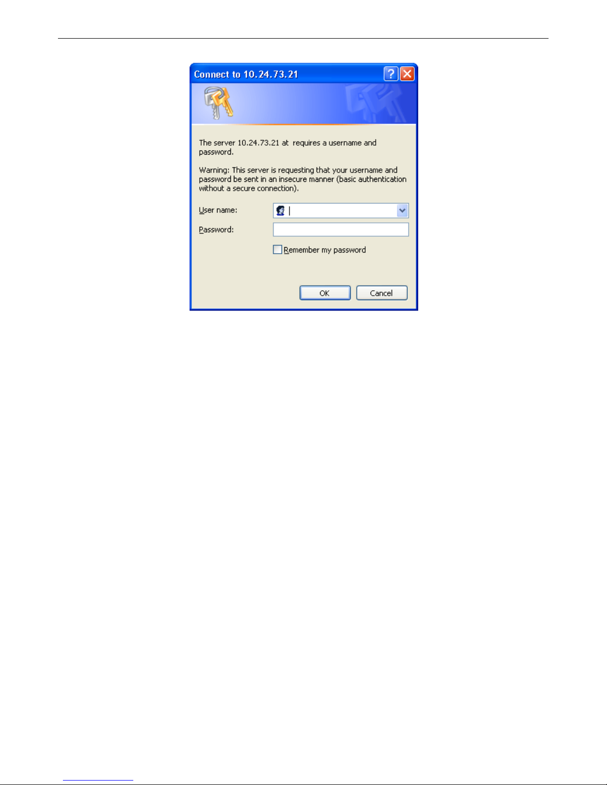
This opens the management module's user authentication dialog box, as seen below.
Page 13
xStack® DGS-3426G Layer 2 Gigabit Ethernet Managed Switch
2
Figure 1- 1 Enter Network Password dialog box
Leave both the User Name field and the Password field blank and click OK. This will open the Web-based user interface. The
Switch management features available in the Web-based manager are explained below.
Web-based User Interface
The user interface provides access to various Switch configuration and management windows, allows the user to view
performance statistics, and permits graphical monitoring of the system status.
Areas of the User Interface
The figure below shows the user interface. Three distinct areas divide the user interface, as described in the table.
Page 14
xStack® DGS-3426G Layer 2 Gigabit Ethernet Managed Switch
3
Area 2
Area 1
Area 3
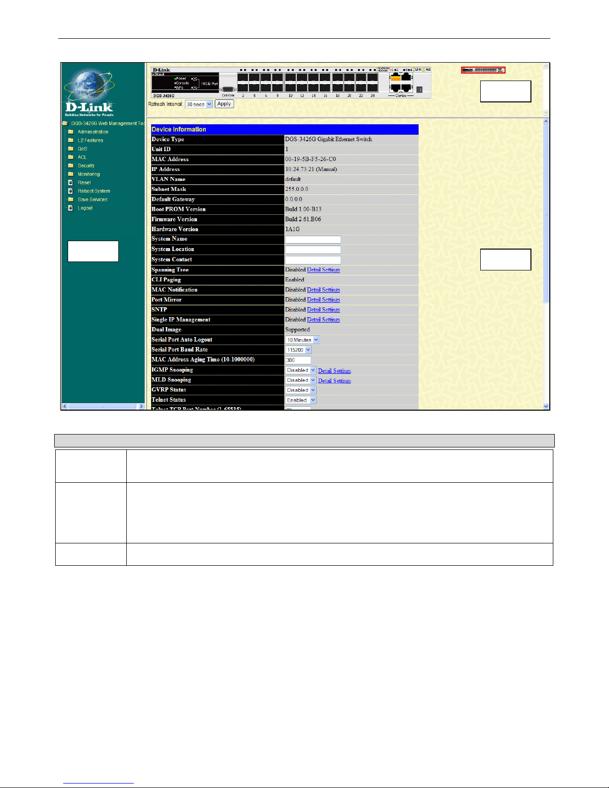
Figure 1- 2 Main Web-Manager window
Area Function
Area 1
Select the menu or window to display. Open folders and click the hyperlinked menu buttons and
subfolders contained within them to display menus. Click the D-Link logo to go to the D-Link website.
Area 2
Presents a graphical near real-time image of the front panel of the Switch. This area displays the
Switch's ports and expansion modules, showing port activity, duplex mode, or flow control,
depending on the specified mode.
Some management functions, including port configuration are accessible here.
Area 3
Presents switch information based on user selection and the entry of configuration data.
Page 15

xStack® DGS-3426G Layer 2 Gigabit Ethernet Managed Switch
4
Web Pages
When connecting to the management mode of the Switch with a web browser, a login screen is displayed. Enter a user name and
password to access the Switch's management mode.
Below is a list of the main folders available in the Web interface:
Administration – Contains the following folders and windows: IP Address, Interface Settings, Stacking, Port Configuration, User
Accounts, Password Encryption, Port Mirroring, System Log, System Severity Settings, SNTP Settings, MAC Notification
Settings, TFTP Services, Multiple Image Services, Ping Test, IPv6 Neighbor, Routing Table, Gratuitous ARP Settings, Static
ARP Settings, DHCP Auto Configuration, DHCP/BOOTP Relay, DHCP Server, DHCP Server Screening, L2PT Tunneling
Settings, RSPAN, SNMP Manager, PoE, sFlow, IP Multicast VLAN Replication, and Single IP Management Settings.
L2 Features – Contains the following folders and windows: VLAN, Trunking, IGMP Snooping, MLD Snooping, Loopback
Detection Global Settings, Spanning Tree, Forwarding & Filtering, LLDP, and QinQ.
QoS – Contains the following folders and windows: Bandwidth Control, QoS Scheduling Mechanism, QoS Output Scheduling,
802.1p Default Priority, and 802.1p User Priority.
ACL – Contains the following following folders and windows: Time Range, Access Profile Table, ACL Flow Meter and CPU
Interface Filtering.
Security – Contains the following folders and windows: Authorization Network State Settings, Traffic Control, Port Security, IP-
MAC-Port Binding, 802.1X, Web Authentication, Trust Host, Access Authentication Control, MAC Based Access Control,
Safeguard Engine, Traffic Segmentation, SSL, SSH, Multiple Authentication, and JWAC.
Monitoring – Contains the following folders and windows: Device Status, Module Information, CPU Utilization, Port Utilization,
Packets, Errors, Packet Size, Browse Router Port, Browse MLD Router Port, VLAN Status, VLAN Status Port, Port Access
Control, MAC Address Table, IGMP Snooping Group, MLD Snooping Group, Switch Logs, Brow se ARP Table, Session Table,
IP Forwarding Table, Browse Routing Table and MAC Based Access Control Authentication Status.
Save Services – Contains the following folders and windows: Save Changes, Configure Information, and Current Configuration
Settings.
Reset, Reboot System and Logout window links are displayed in the main directory.
NOTE: Be sure to configure the user name and password in the User
Accounts window before connecting the Switch to the greater network.
Page 16

xStack® DGS-3426G Layer 2 Gigabit Ethernet Managed Switch
5
Section 2
Administration
DGS-3426G Web Management Tool
IP Address
Interface Settings
Stacking
Port Configuration
User Accounts
Password Encryption
Port Mirroring
System Log
System Severity Settings
SNTP Settings
MAC Notification Settings
TFTP Services
Multiple Image Services
Ping Test
IPv6 Neighbor
Routing Table
Gratuitous ARP Settings
Static ARP Settings
DHCP Auto Configuration Settings
DHCP/BOOTP Relay
DHCP Server
DHCP Server Screening
Layer 2 Protocol Tunneling (L2PT) Settings
RSPAN
SNMP Manager
PoE
sFlow
IP Multicast VLAN Replication
Single IP Management (SIM) Overview
Page 17
xStack® DGS-3426G Layer 2 Gigabit Ethernet Managed Switch
6
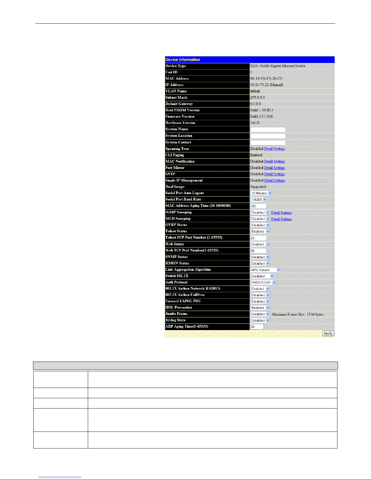
Device Information
The Device Information window contains the main
settings for all major functions for the Switch. It
appears automatically when you log on to the Switch.
To return to the Device Information window after
viewing other windows, click the DGS-3426G Web
Management Tool folder. The Device Information
window shows the Switch’s MAC Address (assigned
by the factory and unchangeable), the Boot PROM,
Firmware Version, Hardware Version and Serial
Number. This information is helpful to keep track of
PROM and firmware updates and to obtain the
Switch's MAC address for entry into another network
device's address table, if necessary. The user may also
enter a System Name, System Location and System
Contact to aid in defining the Switch, to the user's
preference. In addition, this window displays the
status of functions on the Switch to quickly assess
their current global status. Some Functions are hyperlinked for easy access from the Device Information
window.
Many miscellaneous functions are enabled and
disabled in the Device Information window.
Figure 2 - 1 Device Information window
Device Information window configurable parameters include those described in the table below.
Parameter Description
System Name
Enter a system name for the Switch, if so desired. This name will identify it in the Switch
network.
System Location
Enter the location of the Switch, if so desired.
System Contact
Enter a contact name for the Switch, if so desired.
Serial Port Auto
Logout Time
Select the logout time used for the console interface. This automatically logs the user out after
an idle period of time, as defined. Choose from the following options: 2 Minutes, 5 Minutes, 10
Minutes, 15 Minutes or Never. The default setting is 10 minutes.
Serial Port Baud
Rate
This field specifies the baud rate for the serial port on the Switch. The default setting is 115200.
Page 18

xStack® DGS-3426G Layer 2 Gigabit Ethernet Managed Switch
7
MAC Address
Aging Time
This field specifies the length of time a learned MAC Address will remain in the forwarding table
without being accessed (that is, how long a learned MAC Address is allowed to remain idle). To
change this, type in a different value representing the MAC address age-out time in seconds.
The MAC Address Aging Time can be set to any value between 10 and 1,000,000 seconds. The
default setting is 300 seconds.
IGMP Snooping
To enable system-wide IGMP Snooping capability, select Enabled. IGMP snooping is Disabled
by default. Enabling IGMP snooping allows the user to specify use of a multicast router only
(see below). To configure IGMP Snooping for individual VLANs, use the IGMP Snooping
window under the IGMP Snooping folder.
IGMP Multicast
Router Only
This field specifies that the Switch should only forward all multicast traffic to a multicast-enabled
router, if enabled. Otherwise, the Switch will forward all multicast traffic to any IP router. The
default is Disabled.
MLD Snooping
To enable system-wide MLD Snooping capability, select Enabled. MLD snooping is Disabled by
default. Enabling MLD snooping allows you to specify use of a multicast router only (see below).
To configure MLD Snooping for individual VLANs, use the MLD Snooping window under the
MLD Snooping folder.
MLD Multicast
Router Only
This field specifies that the Switch should only forward all multicast traffic to a multicast-enabled
router, if enabled. Otherwise, the Switch will forward all multicast traffic to any IP router. The
default is Disabled.
GVRP Status
Use this drop-down menu to enable or disable GVRP on the Switch.
Telnet Status
Telnet configuration is Enabled by default. If you do not want to allow configuration of the
system through Telnet choose Disabled.
Telnet TCP Port
Number (1-65535)
The TCP port number used for Telnet management of the Switch. The "well-known" TCP port for
the Telnet protocol is 23.
Web Status
Web-based management is Enabled by default. If you choose to disable this by selecting
Disabled, you will lose the ability to configure the system through the Web interface as soon as
these settings are applied.
Web TCP Port
Number (1-65535)
The TCP port number used for Web-based management of the Switch. The "well-known" TCP
port for the Telnet protocol is 80.
SNMP Status
SNMP is Disabled by default. The Switch supports the SNMP versions 1, 2c, and 3. Once
SNMP is enabled, you can choose among three versions to monitor and control the Switch. The
three versions of SNMP vary in the level of security provided between the management station
and the network device.
RMON Status
Remote monitoring (RMON) of the Switch is Enabled or Disabled here.
Link Aggregation
Algorithm
The algorithm that the Switch uses to balance the load across the ports that make up the port
trunk group is defined by this definition. Choose MAC Source, MAC Destination, MAC Src &
Dest, IP Source, IP Destination or IP Src & Dest (See the Link Aggregation section of this
manual).
Switch 802.1X
MAC Address may enable by port or the Switch’s 802.1X function; the default is Disabled. This
field must be enabled to view and configure certain windows for 802.1X. More information
regarding 802.1X, its functions and implementation can be found later in this section, under the
Port Access Entity folder.
Port-Based 802.1X specifies that ports configured for 802.1X are initialized based on the port
number only and are subject to any authorization parameters configured.
MAC-based Authorization specifies that ports configured for 802.1X are initialized based on the
port number and the MAC address of the computer being authorized and are then subject to any
authorization parameters configured.
Auth Protocol
The user may use the drop-down menu to choose between RADIUS EAP and Local for the
802.1X authentication protocol on the Switch. The default setting is RADIUS EAP.
802.1X Authen
Network RADIUS
The user may use the drop-down menu to Enable or Disable the 802.1X Authen Network
RADIUS on the Switch. The default setting is Enabled.
802.1X Authen
FailOver
The user may use the drop-down menu to Enable or Disable the 802.1X Authen FailOver on the
Switch. The default setting is Disabled.
Page 19

xStack® DGS-3426G Layer 2 Gigabit Ethernet Managed Switch
8
Forward EAPOL
PDU
The user may use the drop-down menu to Enable or Disable the Forward EAPOL PDU on the
Switch. The default setting is Disabled.
HOL Prevention
If this option is enabled it prevents the forwarding of data to a port that is blocked. Traffic that
would normally be sent to the buffer memory of the Switch’s TX queue is dropped so that
memory usage is conserved and performance across all ports remains high.
Jumbo Frame
This field will enable or disable the Jumbo Frame function on the Switch. The default is
Disabled. Max. Jumbo frame size = 9216 bytes if this is enabled.
Syslog State
The user may globally enable or disable the Syslog function here by using the drop-down menu.
The default is Disabled.
ARP Aging time
(0-65535)
The user may set the ARP Aging Time here by entering a time between 0 and 65535 minutes.
The default setting is 20 minutes.
Click Apply to implement changes made.
IPv6
The xStack® DGS-3426G has the capability to support the following:
• IPv6 unicast, multicast and anycast addresses
• Allow for IPv6 packet forwarding
• IPv6 fragmentation and re-assembly
• Processing of IPv6 packet and extension headers
• Static IPv6 route configuration
• IPv6 Neighbor Discovery
• Link-Layer Address resolution, Neighbor Unreachability Detection, and Duplicate Address Detection over broadcast
mediums (ex: Ethernet)
• Send Router Advertisement
• ICMPv6 functionality
The following sections will briefly explain IPv6, its functionality and how IPv6 is implemented on this Switch.
Overview
IP version 6 is the logical successor to IP version 4. It was known that IPv4 could not support the amount of addresses that would
eventually be needed for not only each person, but each device that would require an IP address, and therefore a system with a
larger pool of IP addresses was r equired. IPv6 has addressed that issue, along with other issues that enhance routing over the
network, provide better security and improve Quality of Service for Internet users. Some of the improvements made were:
Expanding the Capabilities for IP Addressing – IPv6 has increased the size of the IP address from 32 bits to 128 bits. As a
result, the addressing hierarchy has been greatly expanded, more nodes now have the capability of having a unique IP address an d
the method of assigning an IP address to an interface has become cleaner and quick er. Unicast and multicast addresses still exist
but in a purer form and multicast addresses now have a scope field which increases the scalability of multicast routing. Also, an
anycast address has been added, which will send packets to the closest node which is a part of a group of nodes, thereby
eliminating a specified device for a particular group.
Simplifying the Packet Header – The IPv6 packet header has been simplified from IPv4 as some headers have been modified or
dropped altogether, which improves processing speed and cost. The IPv6 header now has a fixed length of 40 bytes consisting of
an 8-byte header and two 16-byte IP addresses (source and destination).
Extensions and Options Enhancement – Packet header option fields encoding has been enhanced to allow for proficient
forwarding of packets due to lesser restrictions on packet option length and encoding method. This enhancement will also allow
new option fields to be integrated into the IPv6 system without hassles and limitations. These optional headers are placed between
the header and the payload of a packet, if they are necessary at all.
Authentication and Privacy Extension Support – New authentication capabilities use extensions for data integrity and data
confidentiality for IPv6.
Page 20

xStack® DGS-3426G Layer 2 Gigabit Ethernet Managed Switch
9
Flow Labeling – This new capability allows packets to be streamlined into certain traffic “flows” if labeled by the sender. In this
way, services such as “real time services or non-default quality of service can receive special attention for improved flow quality.
Page 21
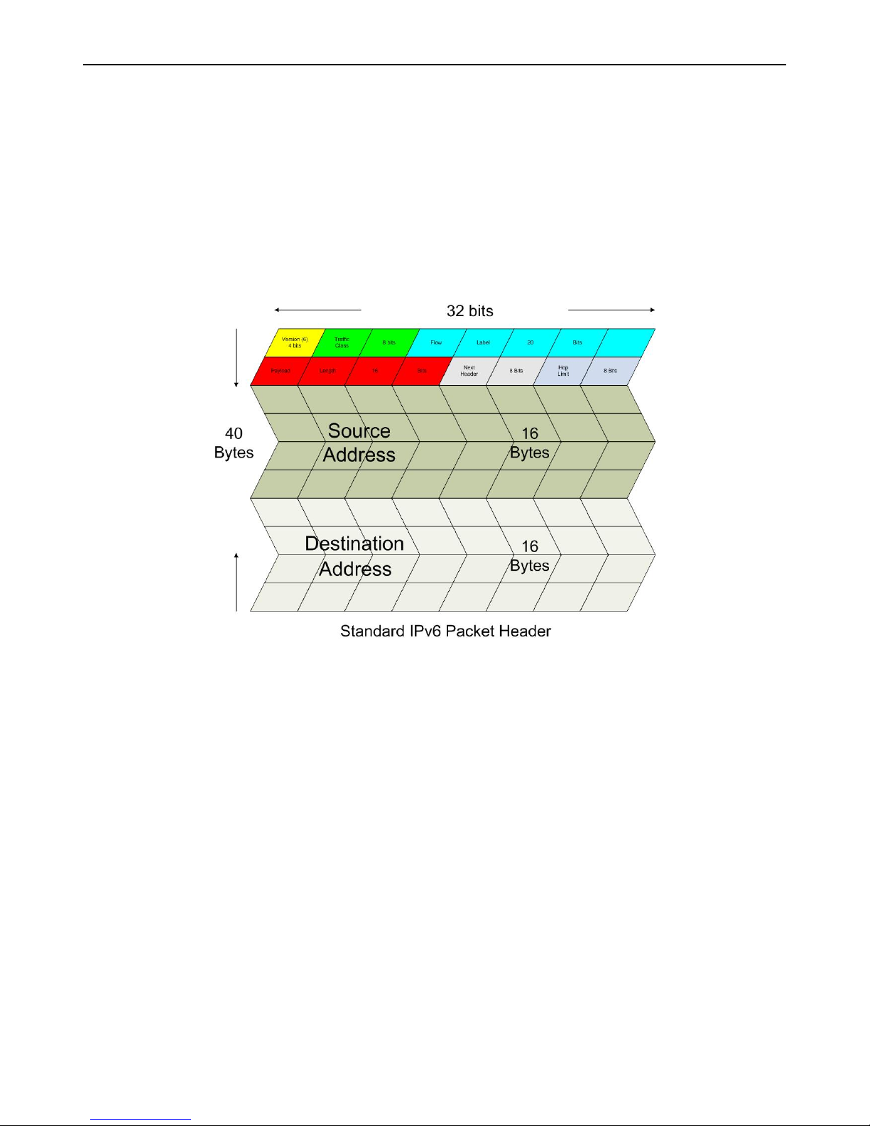
xStack® DGS-3426G Layer 2 Gigabit Ethernet Managed Switch
10
Packet Format
As in IPv4, the IPv6 packet consists of the packet header and the payload, but the difference occurs in the packet header which has
been amended and improved for better packet flow and processing. The following will outline and detail the IPv6 enhancements
and parts of the IPv6 packet, with special attention to the packet header.
IPv6 Header
The IPv6 packet header has been modified and simplified from IPv4. The header length, identification, flags, fragment offset and
header checksum have all been removed in the IPv6 header due to lack of necessity or improvement to a better function of the
header. The minimum header length is now 20 bytes but may be increased to as much as 60 bytes, using 4-byte increment
extensions. The following picture is an example of an IPv6 packet header.
Eight fields make up the basic IPv6 packet header:
Version – This 4-bit field defines the packet version, which is IPv6 and is defined as the number 6.
Traffic Class – This 1-byte field replaces the Type of Service field used in IPv4 and is used to process real-time data and other
data requiring special packet management. This field defines the Class of Service priority of an IPv6 packet.
Flow Label – This 20-bit field is used to facilitate the handling of real-time traffic. Hosts sending data can place a flow label into
this field to identify a sequence of packets that have an identical set of options. In this way, router can process these packets more
efficiently once the flow class has been identified and the rest of the packet header no longer needs to be fully processed, just the
flow label and the source address. All flow label packets must have identical source and destination addresses.
Payload Length – Known as the datagram length in IPv4, this 16-bit field specifies the length of the IPv6 data carried after the
header of the packet. Extension headers are considered part of the payload and are included in the length specified here.
Next Header – This 8-bit field is used to identify the header immediately following the IPv6 header. When this field is set after
the hop by-hop header, it defines the extension header that will appear after the destinatio n address. Each extension head er must
be preceded by a Next Header field. Integers used to define extension headers in the next Header field use the same values as IPv4
(ex: 6=TCP, 17=UDP, etc.).
Hop Limit - Similar to the TTL field in IPv4, this 8-bit field defines the number of hops remaining after the packet has been
processed by a node, instead of the number of seconds left to live as on an IPv4 network . This field will decrement by one after
every node it passes and the packet will be discarded once this field reaches zero.
Source Address – This 16-byte field defines the IPv6 address of the source node sending the packet.
Destination Address – This 16-byte field defines the IPv6 address of the destination node receiving the packet. This may or may
not be the final destination node of this packet, depending on the routing header, if present.
Page 22
xStack® DGS-3426G Layer 2 Gigabit Ethernet Managed Switch
11
Extension Headers
Extension headers are used to identify optional parameters regarding IPv6 packets such as routing, fragmentation of packets or
authentication parameters. The types of extension headers supported are Hop-by-Hop, Routing, Fragment, Destination Options,
Authentication and Encapsulating Security Payload. These extension headers are placed between the IPv6 packet header and the
payload and are linked together by the aforementioned Next Header, as shown below.
IPv6 header
Next Header = TCP
TCP header + data
IPv6 header
Next Header = Routing
Routing Header
Next Header = TCP
TCP header + data
IPv6 header
Next Header =
Destination Options
Destination Options
Header
Next Header = Routing
Routing Header
Next Header = TCP
TCP header + data
Each header has a specific place in the header chain and must follow the following order:
• IPv6 Header
• Hop-By-Hop Header (Must follow the IPv6 header)
• Destination Options
• Routing Header
• Fragment Header
• Authentication Header
• Encapsulating Security Payload Header
• Destination Options Header
• Upper Layer Header
There may be zero, one or more extension headers in the IPv6 header, they must be processed in order and they are to be in
increments of 8 octets in the IPv6 packet. Nodes that do not recognize the field of the extension header will discard the packet and
send a relevant ICMPv6 message back to the source.
Packet Fragmentation
At times, packets are sent out to a destination that exceed the size of the Path MTU, so the source node is required to split these
packets into fragments in individual packets which will be rebuilt when it reaches its final destination. Each of the packets that
will be fragmented is given an Identification value, by the source node. It is essential that each of these Identification values is
different than any other fragmented packet recently sent that include the same source and destination address. The original packet
is divided into two parts, a fragmentable part and an unfragmentable part. The unfragmentable part of the packet consists of the
IPv6 header and any extension headers present, up to the routing extension header. The fragmentable part has the payload plus any
extension headers that must be processed by the final destination node. This part will be divided into multiple packets that ar e of a
size that can be accepted by the Path MTU. The IPv6 header is then included with this fragmented part and sent to its destination.
Once all parts of the fragmented packet reach its destination, they are reassembled using the Fragment Identification value,
provided that the source and destination addresses are identical.
Address Format
To address the problem of finding a larger pool of IP addresses for IPv6, the size and format of the IPv4 format needed to be
changed. Quadrupling the size of the address, from 32 bits to 128 bits, and encoding addresses using the hexadecimal form were
used to solve the prob lem. In IPv4, the format of the address loo ked like xxx.xxx.xxx.xxx, where the x’ s represent integers from
0-9 (ex. 136.145.225.121). Now in IPv6, the format of the address resembles xxxx:xxxx:xxxx:xxxx:xxxx:xxxx:xxxx:xxxx where a
Page 23

xStack® DGS-3426G Layer 2 Gigabit Ethernet Managed Switch
12
set of xxxx represents a 16-bit hexadecimal value (ex. 2D83:0C76:3140:0000:0000:020C:417A:3214). Although this address
looks long and cumbersome, there are some compression rules that will shorten the format of the IPv6 address to make it more
compatible to the user.
One such compression rule that is used is to remove leading zeros from any 16-bit hexadecimal value. This is only for zeros th at
begin the value, not for zeros within the value or ones that are ending the value. Therefore, if we take the previous example IPv6
address and use the compression rules, our IPv6 address would look like this:
2D83:0C76:3140:0000:0000:020C:417A:3214 Æ 2D83:C76:3140:0:0:20C:417A:3214
The second compression method is to change a string of zero bits into two colons. At times, there may be strings of empty values
in the IPv6 address that are unused for this address, but they are necessary for the format of other IPv6 addresses with alternate
purposes. To compress these zero strings, the format “::” is used to represent multiple zero fields in the address. This double colon
can only be used once in the IPv6 address because when a computer finds a colon, it will expand this field with as many zeros as
is necessary to reach the 128-bit address size. If two strings of zeros are present, separated by another non-zero field, a zero must
be used to represent one of the two zero fields. So, if we reduce our example using this compression, it would look like this:
2D83:0C76:3140:0000:0000:020C:417A:3214 Æ 2D83:C76:3140:0:0:20C:417A:3214 Æ2D83:C76:3140::20C:417A:3214
When IPv4 and IPv6 nodes are mixed in a network, the IPv6 notation overcomes the difficulty of using an IPv4 address by
converting it to the IPv6 format using zeros at the beginning of the IPv4 address. For example, an IP address of 192.168.1.1 is
represented in IPv6 format x:x:x:x:d.d.d.d where the x’s are a string of zeros and the d’s represent the normal IPv4 address. (ex.
0:0:0:0:192.168.1.1 or condensed ::192.168.1.1 or hex form ::C0A8:1:1).
Types
IPv6 addresses are classified into three main categories, unicast, multicast and anycast.
Unicast – This address represents a single interface on an IPv6 node. Any packet with a unicast address as its destination address
will only be sent to that specific node. Two types of unicast addresses are mainly used for IPv6.
• Link-Local – Defined by the IPv6 address prefix FE80::/10, link-local addresses allow for communication to occur
between devices on a local link. These addresses are used in neighbor discovery and stateless autoconfiguration.
• Global Aggregateable - Defined using a global routing prefix in the range of 2000::/3 to E000::/3, global addresses are
aggregated using these routing prefixes to produce unique IPv6 addresses, which will limit global routing table entries.
The MAC address of the device is used to produce this address in this form:
Global Routing Prefix + Site Level Aggregator + MAC address (first 3 bits) + FFFE + MAC Address (last 3 bits)
So if your MAC address looks like 00-0C-6E-6B-EB-0C, your IPv6 address may resemble
2000::C:6E:6B:FF:FE:EB:0C/64.
Multicast – Like IPv4, multicast addresses are used to send packets to multiple destinations on a network. These interfaces must
be a part of the multicast group. IPv6 multicast prefixes begin with the prefix FF00::/8. FF represents the binary 1111 1111 which
identifies a multicast address. The first zero, which is a 4-bit integer, represents the lifetime of the packet. An entry of zero in this
field represents a permanent multicast address and an entry of one represents a temporary multicast address. The second zero,
which is also a 4-bit integer, defines the scope of the multicast address. This scope defines to what places the multicast address is
valid. For example, a value of 1 defines the node, 2 defines the link, 5 defines a site, 8 defines a organization and so on. Not all
integers are in use for the scope field. An example of this would be FF02 where the 2 represents a multicast packet going to all the
nodes on a local link.
Anycast – The anycast address will send messages to the nearest node of a particular group. This address is assigned to multiple
interfaces in the group but only the node with the closest proximity will receive the message. These anycast addresses are
allocated from the unicast address space and therefore have no real defined prefix to distinguish it from other IPv6 addresses. The
main purpose of the anycast address is to identify a set of routers owned by an organization providing Internet service. It could
also be used to identify a set of routers connected to a particular subnet or permitting entrance to a specific routing domain.
Two other special types of addresses exist in IPv6. The unspecified address has a value of 0:0:0:0:0:0:0:0 which is comparable to
the 0.0.0.0 address in IPv4. This address is used to indicate the lack of a valid IP address on a node and may be used by a device
when booting and requesting address configuration notification. In its IPv6 condensed form, it appears as “::” and should not be
statically or dynamically assigned to an interface, nor should it be the destination address of an IPv6 packet, or located within the
routing header.
The second type of special address is the loopback address which is represented by 0:0:0:0:0:0:0:1, or ::1 in its compressed form.
It is akin to the 127.0.0.1 address in IPv4 and is used in troubleshooting and testing IP stacks. This address, like the unspecified
address, and should not be statically or dynamically assigned to an interface.
Page 24

xStack® DGS-3426G Layer 2 Gigabit Ethernet Managed Switch
13
ICMPv6
Network professionals are already very familiar with ICMP for IPv4, which is an essential tool in the IPv4 network, relaying
messages about network problems and the general condition of the network. ICMPv6 is the successor to the IPv4 version and
performs many of the same basic functions as its precursor, yet is not compatible with ICMPv4. ICMPv6 has made improvements
over its forerunner, with such enhancements as managing multicast group memberships and allowing for neighbor discovery by
resolving link-layer addresses attached to the same link and identifying changes in those addresses. ICMP can also discover
routers, determine which neighbors can be reached and map IP addresses to MAC addresses within the network. ICMPv6 is a vital
part of the IPv6 network and must be implemented on every IPv6 node for operations to function normally.
Two kinds of ICMP messages are apparent on the IPv6 network:
Error Messages – ICMP error messages are sent out on the network when packet sizes exceed the path MTU (Maximum Transfer
Unit), when the hop count of the IPv6 packet has been surpassed, when messages cannot reach their intended destination and
when there are parameter problems within the IPv6 packet.
Informational Messages – ICMP informational messages send out packets describing current network information valuable to
devices on the network. A common and useful ICMPv6 informational message is the ping program use to discover the availability
a device, by using a ping request and reply format. Other informational messages include Path MTU discovery, which is used to
determine the maximum size of data packets that can be allowed to be transferred, and N eighbor Discovery messages, which
discover routers that can forward packets on the network. Neighbor discovery will be discussed further in the next section.
Neighbor Discovery
Neighbor discovery is a new feature incorporated in IPv6. In IPv4, no means were available to tell if a neighbor could be reached.
Now, combining ICMP messages and ARP, neighbors can be detected and their layer 2 addresses (MAC Address) can be
identified. This feature can also discover neighboring routers th at can forward p ackets and keep track of the reach ability o f routers,
as well as if changes occur within link-layer addresses of nodes on the network or identical unicast addresses are present on the
local link.
The functionality of the Neighbor Discovery feature is based on ICMPv6 packets, Neighbor Solicitation and Router
Advertisement messages circulating on the network. When a node wishes to determine link layer addresses of other nodes on the
same link, it produces a Neighbor Solicitation message to be circulated on the local link. When received by a neighbor, this
neighbor will produce Router Advertisements immediately to be returned. These Router Advertisements will contain a multicast
address as the destination address and have an ICMP type of 134 (the specified number for Router Advertisements), as well as
having the link-layer address of the node sending the advertisement. Router Advertisement messages may be periodic, specified in
the advertisement by having the all-nodes multicast address FF02::1, or sent out as a result of receiving a Neighbor Solicitation
message, specified in the advertisement by having the address of the interface that first sent the solicitation message. Once
confirmation of the Neighbor has been reached, packets can now be exchanged on the link.
Neighbor Unreachability Detection
At times on the network, problems occur in reaching the Neighbor node or getting a response from the Neighbor. A neighbor is
considered reachable when it has received and processed packets sent to it, and in return sends a packet back notifying a
affirmative response. This response may come in the form of an indication from an upper-layer protocol, like TCP, noting that
progress is being made, or in response from a Neighbor Solicitation message in the form of a Router Advertisement message. If
responses are not received from the node, it is considered unreachable and a Destination Unreachable message is received in the
form of an ICMP packet. This Destination Unreachable ICMP packet will contain the reason for the fault, located in the code field
of the ICMP header. Five possible reasons for the failure can be stated:
1. There is no route or destination (Code 0).
2. Communication has been administratively prohibited, such as a firewall or filter (Code 1)
3. Beyond the scope of the source address, when the multicast scope of the source address is smaller than the scope of the
destination address (Code 2)
4. The address is unreachable (Code 3)
5. The port is unreachable (Code 4)
Page 25

xStack® DGS-3426G Layer 2 Gigabit Ethernet Managed Switch
14
Duplicate Address Detection (DAD)
DAD messages are used to specify that there is more than one node on a local link possessing the same IP address. IPv6 addresses
are only leased for a defined period of time. When that time expires, the address will become invalid and another address must be
addressed to the node. To ensure that this new address is unique on the local link, a node runs a DAD process to determine the
uniqueness of the new address. This is done through th e use of a Neighbor Solicitation message containing a Tentative addr ess.
This message will detect if another node on the local link has this Tentative address. If the Tentative address is found on another
node, that node will send out a Neighbor Advertisement message, the process will be terminated, and manual configuration will be
necessary. If no answer is forthcoming regarding this Neighbor Solicitation message containing the tentative address, the address
is allotted to the node and connectivity is established.
Assigning IP Addresses
For IPv4 addresses, users may only assign one address per interface and only one address may be used on a particular VLAN. Yet,
IPv6 addresses are different. All IPv6 interfaces on the switch must have at least one IPv6 link-local unicast address, if the user is
employing the IPv6 addressing scheme. Multiple IPv6 addresses may be configured for IPv6 interfaces, regardless of type,
whether it is unicast, multicast or anycast. The scope of the address has some bearing on the assigning multiple addresses to a
single interface as well. If multiple physical interfaces are considered as one interface on the Internet layer, multiple unicast
addresses may be alloted to multiple physical interfaces, which would be beneficial for load sharing on these interfaces. This is
dependent on these unicast addresses having a scope smaller than the link-local address, if these unicast addresses are not the
source or destination address for IPv6 packets to or from address that are not IPv6 neighbors of the interface in question.
IP Interface Setup
Each VLAN must be configured prior to setting up the VLAN’s corresponding IP interface.
An example is presented below:
VLAN Name VID Switch Ports
System (default) 1 5, 6, 7, 8, 21, 22, 23, 24
Engineer 2 9, 10, 11, 12
Marketing 3 13, 14, 15, 16
Finance 4 17, 18, 19, 20
Sales 5 1, 2, 3, 4
Backbone 6 25, 26
Table 2- 1 VLAN Example - Assigned Ports
In this case, six IP interfaces are required, so a CIDR notation of 10.32.0.0/11 (or a 11-bit) addressing scheme will work. This
addressing scheme will give a subnet mask of 11111111.11100000.00000000.00000000 (binary) or 255.224.0.0 (decimal).
Using a 10.xxx.xxx.xxx IP address notation, the above example would give six network addresses and six subnets.
Any IP address from the allowed range of IP addresses for each subnet can be chosen as an IP address for an IP interface on the
switch.
For this example, we have chosen the next IP address above the network address for the IP interface’s IP Address:
VLAN Name VID Network Number IP Address
System (default) 1 10.32.0.0 10.32.0.1
Engineer 2 10.64.0.0 10.64.0.1
Marketing 3 10.96.0.0 10.96.0.1
Finance 4 10.128.0.0 10.128.0.1
Sales 5 10.160.0.0 10.160.0.1
Backbone 6 10.192.0.0 10.192.0.1
Table 2- 2 VLAN Example – Assigned IP Interfaces
Page 26
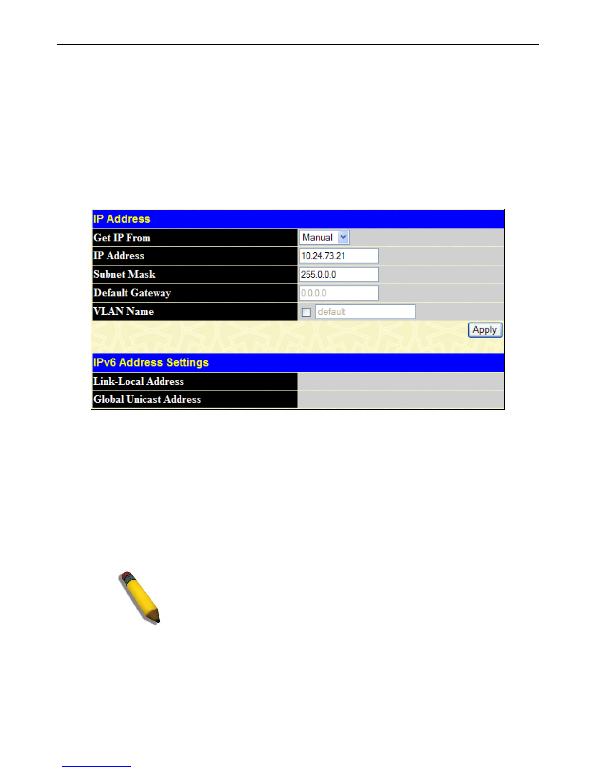
xStack® DGS-3426G Layer 2 Gigabit Ethernet Managed Switch
15
The six IP interfaces, each with an IP address (listed in the table above), and a subnet mask of 255.224.0.0 can be entered into the
Setup IP Interface window.
IP Address
The IP Address may initially be set using the console interface prior to connecting to it through the Ethernet. If the Switch IP
address has not yet been changed, read the introduction of the xStack
®
DGS-3426G CLI Manual for more information. To change
IP settings using the web manager you must access the IP Address menu located in the Administration folder.
To configure the Switch's IPv4 address:
To view this window, click Administration > IP Address, as shown below:
Figure 2 - 2 IP Address Settings window
To manually assign the Switch's IP address, subnet mask, and default gateway address:
1. Select Manual from the Get IP From drop-down menu.
2. Enter the appropriate IP Address and Subnet Mask.
3. If accessing the Switch from a different subnet from the one it is installed on, enter the IP address of the Default Gateway.
If managing the Switch from the subnet on which it is installed, the user may leave the default address (0.0.0.0) in this
field.
4. If the Switch has no previously configured VLANs, the user can use the default VLAN Name. The default VLAN
contains all of the Switch ports as members. If the Switch has previously configured VLANs, the user will need to enter
the VLAN ID of the VLAN that contains the port connected to the management station that will access the Switch. The
Switch will allow management access from stations with the same VID listed here.
NOTE: The Switch's factory default IP address is 10.90.90.90 with a
subnet mask of 255.0.0.0 and a default gateway of 0.0.0.0.
To use the BOOTP or DHCP protocols to assign the Switch an IP address, subnet mask, and default gateway address:
Use the Get IP From: drop-down menu to choose from BOOTP or DHCP. This selects the method the Switch assigns an IP
address on the next reboot.
The following fields can be set or modified:
Page 27

xStack® DGS-3426G Layer 2 Gigabit Ethernet Managed Switch
16
Parameter Description
BOOTP
The Switch will send out a BOOTP broadcast request when it is powered up. The BOOTP protocol
allows IP addresses, network masks, and default gateways to be assigned by a central BOOTP
server. If this option is set, the Switch will first look for a BOOTP server to provide it with this
information before using the default or previously entered settings.
DHCP
The Switch will send out a DHCP broadcast request when it is powered up. The DHCP protocol
allows IP addresses, network masks, and default gateways to be assigned by a DHCP server. If
this option is set, the Switch will first look for a DHCP server to provide it with this information
before using the default or previously entered settings.
Manual
Allows the entry of an IP address, Subnet Mask, and a Default Gateway for the Switch. These
fields should be of the form xxx.xxx.xxx.xxx, where each xxx is a number (represented in decimal
form) between 0 and 255. This address should be a unique address on the network assigned for
use by the network administrator.
Subnet Mask
A Bitmask that determines the extent of the subnet that the Switch is on. Should be of the form
xxx.xxx.xxx.xxx, where each xxx is a number (represented in decimal) between 0 and 255. The
value should be 255.0.0.0 for a Class A network, 255.255.0.0 for a Class B network, and
255.255.255.0 for a Class C network, but custom subnet masks are allowed.
Default
Gateway
IP address that determines where packets with a destination address outside the current subnet
should be sent. This is usually the address of a router or a host acting as an IP gateway. If your
network is not part of an intranet, or you do not want the Switch to be accessible outside your local
network, you can leave this field unchanged.
VLAN Name
This allows the entry of a VLAN Name from which a management station will be allowed to manage
the Switch using TCP/IP (in-band via Web manager or Telnet). Management stations that are on
VLANs other than the one entered here will not be able to manage the Switch in-band unless their
IP addresses are entered in the Security IP Management window. If VLANs have not yet been
configured for the Switch, the default VLAN contains all of the Switch's ports. There are no entries
in the Security IP Management table, by default, so any management station that can connect to
the Switch can access the Switch until a management VLAN is specified or Management Station IP
Addresses are assigned.
Click Apply to implement changes made.
This window also contains the current IPv6 setup on the Switch. Configuring IPv6 interfaces can be done in under the Interface
Settings heading, by clicking the link IPv6 Interface Settings, which will be discussed in the next section.
Setting the Switch's IP Address using the Console Interface
Each Switch must be assigned its own IP Address, which is used for communication with an SNMP network manager or other
TCP/IP application (for example BOOTP, TFTP). The Switch's default IP address is 10.90.90.90. The default Switch IP address
can be changed to meet the specification of your networking address scheme.
The IP address for the Switch must be set before the Web-based manager can manage the switch. The Switch IP address can be
automatically set using BOOTP or DHCP protocols, in which case the actual address assigned to the Switch must be known. The
IP address may be set using the Command Line Interface (CLI) over the console serial port as follows:
• Starting at the command line prompt, enter the commands config ipif System ipaddress xxx.xxx.xxx.xxx/
yyy.yyy.yyy.yyy. Where the x's represent the IP address to be assigned to the IP interface named System and the y's
represent the corresponding subnet mask.
• Alternatively, the user can enter config ipif System ipaddress xxx.xxx.xxx.xxx/z. Where the x's represent the IP
address to be assigned to the IP interface named System and the z represents the correspond ing number of subnets in
CIDR notation.
The IP interface named System on the Switch can be assigned an IP address and subnet mask, which can then be used to connect a
management station to the Switch's Telnet or Web-based management agent.
Successful entry of the command will produce a “Success” message, indicating that the command execution was correctly. The
user may now utilize this address to configure or manage the Switch through Telnet, the Command Line Interface (CLI) or the
Web-based management (GUI).
Page 28

xStack® DGS-3426G Layer 2 Gigabit Ethernet Managed Switch
17
Interface Settings
The IP address may initially be set using the console interface prior to connecting to it through the Ethernet. If the Switch IP
address has not yet been changed, read the introduction of the xStack
®
DGS-3426G CLI Manual for more information. To change
IP settings using the Web manager, users must access the IP Address window (Administration > IP Address). Open
Administration folder and click Interface Settings to access two folders to set up IP interfaces on the Switch, one for IPv4
addresses, IPv4 Interface Settings, and one for IPv6 addresses, IPv6 Interface Settings.
IPv4 Interface Settings
To view this window, click Administration > Interface Settings > IPv4 Interface Settings, as shown below:
Figure 2 - 3 IPv4 Interface Settings window
To manually assign the Switch's IPv4 address and its related configurations, click the Add button, revealing the following window
to configure.
Figure 2 - 4 IPv4 Interface Settings - Add
To modify an existing Interface, click that interface’s hyperlinked Interface Name, which will produce this window:
Figure 2 - 5 IPv4 Interface Settings – Modify
Enter a name for the new interface to be added in the Interface Name field (if editing an IP interface, the Interface Name will
already be in the top field as seen in the window above). Enter the interface’s IP address and subnet mask in the corresponding
Page 29
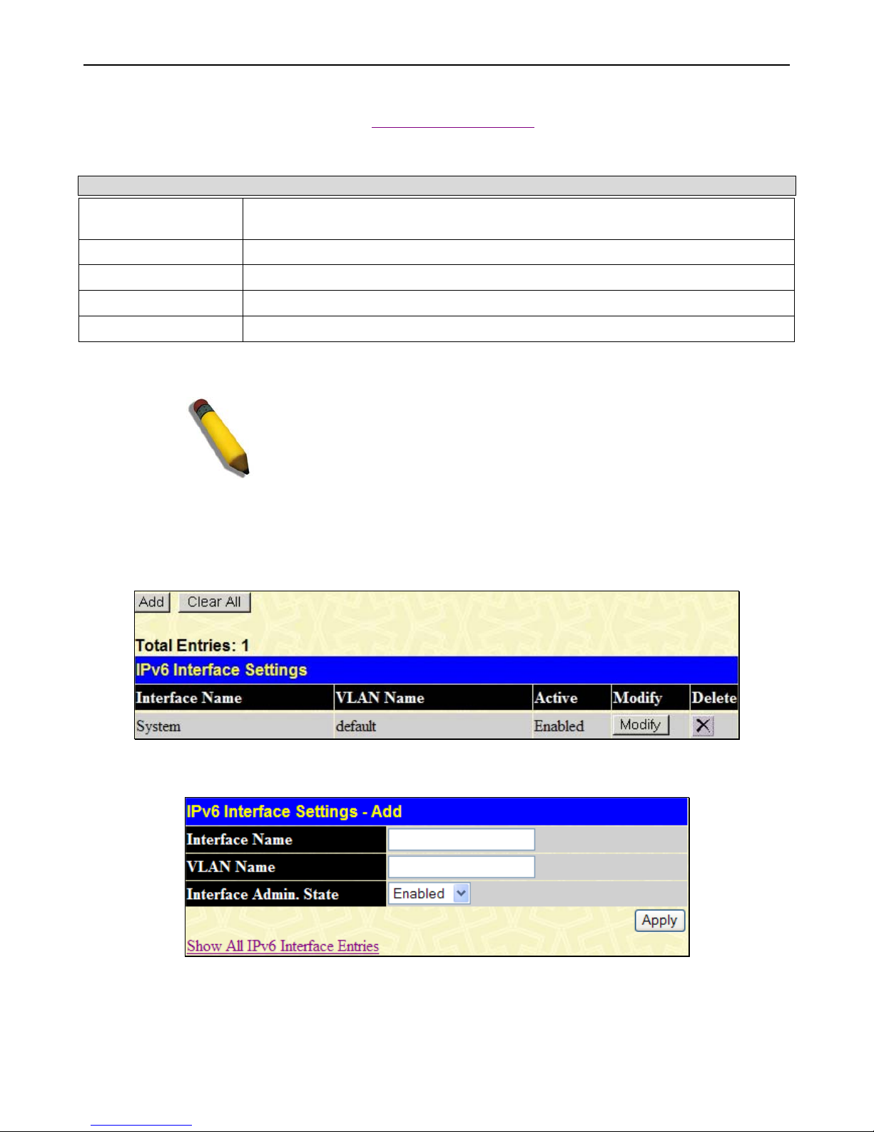
xStack® DGS-3426G Layer 2 Gigabit Ethernet Managed Switch
18
fields. Pull the Interface Admin State drop-down menu to Enabled and click Apply to enter to make the IP interface effective. To
view entries in the IP Interface Settings, click the Show All IP Interface Entries
hyperlink. Use the Save Changes dialog box
from the Save Services folder to enter the changes into NV-RAM.
The following fields can be set or modified:
Parameter Description
Interface Name
This field displays the name for the IP interface or it is used to add a new interface created
by the user. The default IP interface is named “System”.
IP Address
This field allows the entry of an IPv4 address to be assigned to this IP interface.
Subnet Mask
This field allows the entry of a subnet mask to be applied to this IP interface.
VLAN Name
This field displays the VLAN name directly associated with this interface.
Interface Admin. State
Use the drop-down menu to enable or disable configuration on this interface.
Click Apply to implement changes made.
NOTE: The Switch's factory default IP address is 10.90.90.90 with a
subnet mask of 255.0.0.0 and a default gateway of 0.0.0.0.
IPv6 Interface Settings
This window is used to set up IPv6 interfaces and addresses for the Switch.
To view this window, click Administration > Interface Settings > IPv6 Interface Settings, as shown below:
Figure 2 - 6 IPv6 Interface Settings window
To add a new IPv6 interface, click the Add button, which will display the following window.
Figure 2 - 7 IPv6 Interface Settings – Add
To add an Interface, enter an Interface Name in the field provided, along with a corresponding VLAN Name, set the Interface
Admin. State to Enabled and click Apply. Newly created interfaces will appear in the IPv6 Interface Settings window.
To change the settings for a configured Interface, click the corresponding Modify button, which will display the following
window for the user to configure.
Page 30
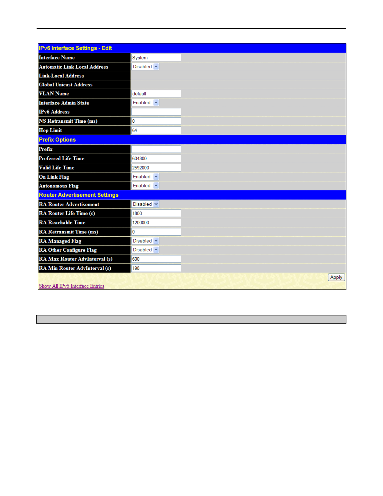
xStack® DGS-3426G Layer 2 Gigabit Ethernet Managed Switch
19
Figure 2 - 8 IPv6 Interface Settings – Edit
The following fields may be viewed or modified. Click Apply to set the changes made.
Parameter Description
Interface Name
This field displays the name for the IP interface or it is used to add a new interface or
change an existing interface name. The default IP interface is named “System”.
The Interface field is used for addresses on the link-local network. It is recommended that
the user enter the specific interface for a link-local IPv6 address. For Global Ipv6
addresses, this field may be omitted.
Automatic Link Local
Address
Use this drop-down menu to enable or disable the Automatic Link Local Address. When
enabled, the switch will automatically create an IPv6 link-local address for the switch.
Once the user enables this feature and clicks Apply, an IPv6 address will be produced
based on the MAC address of the switch and the new entry will appear in the following
Link-Local Address field.
Link-local Address
This field displays the IPv6 address created automatically by the Switch, based on the
MAC Address of the Switch. This is a site local address used only for local routing.
Global Unicast
Address
This field is the unicast address that will be used by the Switch for packets coming from
outside the site-local address, or the public IPv6 address, when connected directly to the
Internet.
VLAN Name
This field states the VLAN Name directly associated with this interface.
Page 31

xStack® DGS-3426G Layer 2 Gigabit Ethernet Managed Switch
20
Interface Admin State
Use the drop-down menu to enable or disable configuration on this interface.
IPv6 Address
Use this field to set a Global Unicast Address for the Switch. This address will be used to
access the network outside of the local link.
NS Retransmit Time
Use this field to set the interval, in seconds that this Switch will produce Neighbor
Solicitation packets to be sent out over the local network. This is used to discover IPv6
neighbors on the local link. The user may select a time between 0 and 65535
milliseconds. Very fast intervals, represented by a low number, are not recommended for
this field.
Hop Limit
This field sets the number of nodes that this Router Advertisement packet will pass before
being dropped. This number is set to depreciate by one after every node it reaches and
will be dropped once the Hop Limit reaches 0. The user may set the Hop Limit between 1
and 255 with a default value of 64.
Prefix Options
Prefix
Use this field to set a prefix for Global Unicast IPv6 addresses to be assigned to other
nodes on the link-local network. This prefix is carried in the Router Advertisement
message to be shared on the link-local network. The user must first have a Global
Unicast Address set for the Switch.
Preferred Life Time
This field states the time that this prefix is advertised as being preferred on the link local
network, when using stateless address configuration. The user may configure a time
between 0 and 4294967295 milliseconds, with a default setting of 604800 milliseconds.
Valid Life Time
This field states the time that this prefix is advertised as valid on the link local network,
when using stateless address configuration. The user may configure a time between 0
and 4294967295 milliseconds.
On Link Flag
Setting this field to Enabled will denote, within the IPv6 packet, that the IPv6 prefix
configured here is assigned to this link-local network. Once traffic has been successfully
sent to these nodes with this specific IPv6 prefix, the nodes will be considered reachable
on the link-local network.
Autonomous Flag
Setting this field to Enabled will denote that this prefix may be used to autoconfigure IPv6
addresses on the link-local network.
Router Advertisement Settings
RA Router
Advertisement
Use this drop-down menu to enable or disable the switch as being capable of accepting
solicitation from a neighbor, and thus becoming an IPv6 neighbor. Once enabled, this
Switch is now capable of producing Router Advertisement messages to be returned to
querying neighbors.
RA Router Lifetime (s)
This time represents the validity of this interface to be the default router for the link-local
network. A value of 0 represents that this Switch should not be recognized as the default
router for this link-local network. The user may set a time between 0 and 9000 seconds
with a default setting of 1800 seconds.
RA Reachable Time
This field will set the time that remote IPv6 nodes are considered reachable. In essence,
this is the Neighbor Unreachability Detection field once confirmation of the access to this
node has been made. The user may set a time between 0 and 36000000 milliseconds
with a default setting of 1200000 milliseconds. A very low value is not recommended.
RA Retransmit Time
(ms)
Used to set an interval time between 0 and 4294967295 milliseconds for the dispatch of
router advertisements by this interface over the link-local network, in response to a
Neighbor Solicitation message. If this Switch is set as the default router for this local link,
this value should not exceed the value stated in the Life Time field previously mentioned.
Setting this field to zero will specify that this switch will not specify the Retransmit Time
for the link-local network. (therefore it will be specified by another router on the link-local
network. The default value is 0 milliseconds.
RA Managed Flag
Use the drop-down menu to enable or disable the Managed flag. When enabled, this will
trigger the router to use a stateful autoconfiguration process to get both Global and linklocal IPv6 addresses for the Switch. The default setting is Disabled.
Page 32

xStack® DGS-3426G Layer 2 Gigabit Ethernet Managed Switch
21
RA Other Configure
Flag
Use the drop-down menu to enable or disable the Managed flag. When enabled, this will
trigger the router to use a stateful autoconfiguration process to get configuration
information that is not address information, yet is important to the IPv6 settings of the
Switch. The default setting is Disabled.
RA Max Router
AdvInterval (s)
Used to set the maximum interval time between the dispatch of router advertisements by
this interface over the link-local network. This entry must be no less than 4 seconds (4000
milliseconds) and no more than 1800 seconds. The user may configure a time between 4
and 1800 seconds with a default setting of 600 seconds.
RA Min Router
AdvInterval (s)
Used to set the minimum interval time between the dispatch of router advertisements by
this interface over the link-local network. This entry must be no less then 3 seconds and
no more than .75 (3/4) of the MaxRtrAdvInterval. The user may configure a time between
3 and 1350 seconds with a default setting of 198 seconds.
Stacking
From firmware release v2.00 of this Switch, the xStack® DGS-3426G now supports switch stacking, where a set of twelve
switches can be combined to be managed by one IP address through Telnet, the GUI interface (web), the console port or through
SNMP. Each switch of this series has either two or three stacking slots located at the rear of the device, which can be used to add
10-gigabit DEM-410CX or DEM-410X stacking modules, sold separately. After adding these stacking ports, the user may connect
these ports together using copper or fiber stacking cables (also sold separately) in one of two possible topologies.
Duplex Ring – As shown in Figure 6-9, the Duplex Ring stacks switches in a ring or circle format where data can be transferred
in two directions. This topology is very resilient because if there is a break in the ring, data can still be transferred through the
stacking cables between switches in the stack.
Duplex Chain – As shown in Figure 6-10, The Duplex Chain topology stacks switches together in a chain-link format. Using this
method, data transfer is only possible in one direction and if there is a break in the chain, then data transfer will obviously be
affected.
DGS-3424G
Switches
DGS-3424G
Switches
Figure 2 - 9 Switches stacked in a Duplex Ring Figure 2 - 10 Switches stacked in a Duplex Chain
Within each of these topologies, each switch plays a role in the Switch stack. These roles can be set by the user per individual
Switch, or if desired, can be automatically determined by the switch stack. Three possible roles exist when stacking the xStack
®
DGS-3426G.
Primary Master – The Primary Master is the leader of the stack. It will maintain normal operations, monitor operations and the
running topology of the Stack. This switch will also assign Stack Unit IDs, synchronize configurations and transmit commands to
remaining switches in the switch stack. The Primary Master can be manually set by assigning this Switch the highest priority (a
lower number denotes a higher priority) before physically assembling the stack, or it can be determined au tomatically b y the stack
through an election process, which determines the lowest MAC address. It will then assign that switch as the Primary Master, if all
Page 33

xStack® DGS-3426G Layer 2 Gigabit Ethernet Managed Switch
22
priorities are the same. The Primary master is physically displayed by the seven segment LED to the far right on the front panel of
the switch where this LED will flash between its given Box ID and ‘H’.
Backup Master – The Backup Master is the backup to the Primary Master, and will take over the functions of the Primary Master
if the Primary Master fails or is removed from the Stack. It also monitors the status of neighboring switches in the stack, will
perform commands assigned to it by the Primary Master and will monitor the running status of the Primary Master. The Backup
Master can be set by the user by assigning this Switch the second highest priority before physically assembling the stack, or it can
be determined automatically by the stack through an election process which determines the second lowest MAC address and then
will assign that switch as the Backup Master, if all priorities are the same.
Slave – Slave switches constitute the rest of the switch stack and although not Primary or Backup Masters, they can be placed into
these roles when these other two roles fail or are removed from the stack. Slave switches perform operations requested by the
master, monitor the status of neighbor switches in the stack and the stack topology and adhere to the Backup Master’s commands
once it becomes a Primary Master. Slave switches will do a self-check to determine if it is to become the Backup Master if the
Backup Master is promoted to the Primary Master, or if the Backup Master fails or is removed from the switch stack. If both
Primary and Backup masters fail, or are removed from the Switch stack, it will determine if it is to become the Primary Master.
These roles will be determined, first by priority and if the priority is the same, the lowest MAC address.
Once switches have been assembled in the topology desired by the user and powered on, the stack will undergo three processes
until it reaches a functioning state.
Initialization State – This is the first state of the stack, where the runtime codes are set and initialized and the system conducts a
peripheral diagnosis to determine each individual switch is functioning properly.
Master Election State – Once the codes are loaded and initialized, the stack will undergo the Master Election State where it will
discover the type of topology used, elect a Primary Master and then a Backup Master.
Synchronization State – Once the Primary Master and the Backup Master have been established, the Primary Master will assign
Stacking Unit IDs to switches in the stack, synchronize configurations for all switches and then transmit commands to the rest of
the switches based on the user’s configurations of the Primary Master.
Once these steps have been completed, the switch stack will enter a normal operating mode.
Stack Switch Swapping
The stacking feature of the xStack® DGS-3426G supports “hot swapping” of switche s in and out of the running stack. Users may
remove or add switches to the stack without powering down or largely affecting the transfer of data between switches in the stack,
with a few minor provisions.
When switches are “hot inserted” into the running stack, the new switch may take on the Backup Master or Slave role, depending
on configurations set on the newly added switch, such as configured priority or MAC address. The new device will not be the
Primary Master, if adding one switch at a time to the Stack. Yet, if adding two stacks together that have both previously
undergone the election process, and therefore both have a Primary Master and a Backup master, a new Primary Master will be
elected from one of the already existing Primary Masters, based on priority or MAC address. This Primary Master will take over
all of the Primary Master’s roles for all new switches that were hot inserted. This process is done using discovery packets that
circulate through the switch stack every 1.5 seconds until the discovery process has been completed.
The “hot remove” action means removing a device from the stack while the stack is still running. The hot removal is detected by
the stack when it fails to receive heartbeat packets during its specified interval from a device, or when one of the stacking ports
links is down. Once the device has been removed, the remaining switches will update their stacking topology database to reflect
the change. Any one of the three roles, Primary Master, Backup Master or Slave, may be removed from the stack, yet different
processes occur for each specific device removal.
If a Slave device has been removed, the Primary Master will inform other switches of the hot remove of this device through the
use of unit leave messages. Switches in the stack will clear the configurations of the unit removed, and dynamically learned
databases, such as ARP, will be cleared as well.
If the Backup Master has been hot removed, a new Backup Master will be chosen through the election process previously
described. Switches in the stack will clear the configurations of the unit removed, and dynamically learned databases, such as
ARP, will be cleared as well. Then the Backup Master will begin backing up the Primary Master when the database
synchronization has been completed by the stack.
If the Primary Master is removed, the Backup Master will assume the Primary Master’s role and a new Backup Master will be
chosen using the election process. Switches in the stack will clear the configurations of the unit removed, and dynamically learned
databases, such as ARP, will be cleared as well. The new Primary Master will inherit the MAC and IP address of the previous
Primary Master to avoid conflict within the stack and the network itself.
Page 34

xStack® DGS-3426G Layer 2 Gigabit Ethernet Managed Switch
23
If both the Primary Master and the Back up Master ar e removed, the election process is immediately processed and a new Primary
Master and Backup Master are determined. Switches in the stack will clear the configurations of the units removed, and
dynamically learned databases, such as ARP, will be cleared as well. Static switch configurations still remain in the database of
the remaining switches in the stack and those functions will not be affected.
NOTE: If there is a Box ID conflict when the stack is in the discovery phase, the device
will enter a special standalone topology mode. Users can only get device information,
configure Box IDs, save and reboot. All stacking ports will be disabled and an error
message will be produced on the local console port of each device in the stack. Users
must reconfigure Box IDs and reboot the stack.
Stacking Mode Settings
To begin the stacking process, users must first enable this device for stacking by using the Stacking Mode Settings window.
To view this window, click Administration > Stacking > Mode Settings, as shown below:
Figure 2 - 11 Stacking Mode Settings window
Use the drop-down menu, choose Enabled and click Apply to allow stacking of this Switch.
Box Information
This window is used to configure stacking parameters associated with all switches in the xStack® DGS-3426G. The user may
configure parameters such as box ID, box priority and pre-assigning model names to switches to be entered into the switch stack.
To view this window, click Administration > Stacking > Box Information, as shown below:
Figure 2 - 12 Box Information window
Parameter Description
Current Box ID
The Box ID of the switch in the stack to be configured.
New Box ID
The new box ID of the selected switch in the stack that was selected in the Current Box ID field.
The user may choose any number between 1 and 12 to identify the switch in the switch stack.
Auto will automatically assign a box number to the switch in the switch stack.
Priority
Displays the priority ID of the Switch. The lower the number, the higher the priority. The box
(switch) with the lowest priority number in the stack is the Primary Master switch. The Primary
Master switch will be used to configure applications of the switch stack.
Information configured in this window is found in the Monitoring folder under Stacking Information.
Page 35

xStack® DGS-3426G Layer 2 Gigabit Ethernet Managed Switch
24
NOTE: Configured box priority settings will not be implemented until users
physically save it using the Web GUI or the CLI.
Port Configuration
To view this window, click Administration >
Port Configuration > Port Configuration, as
shown on the right:
To configure switch ports:
1. Choose the port or sequential range of
ports using the From/To port dropdown menus.
2. Use the remaining drop-down menus
to configure the parameters described
below:
Figure 2 - 13 Port Configuration window
The following parameters can be configured:
Parameter Description
State
Toggle the State field to either enable or disable a given port or group of ports.
Flow Control
Displays the flow control scheme used for the various port configurations. Ports configured for
full-duplex use 802.3x flow control, half-duplex ports use backpressure flow control, and Auto
ports use an automatic selection of the two. The default is Disabled.
Learning
Enable or disable MAC address learning for the selected ports. When Enabled, destination and
source MAC addresses are automatically listed in the forwarding table. When learning is
Disabled, MAC addresses must be manually entered into the forwarding table. This is
sometimes done for reasons of security or efficiency. See the section on Forwarding/Filtering
for information on entering MAC addresses into the forwarding table. The default setting is
Page 36

xStack® DGS-3426G Layer 2 Gigabit Ethernet Managed Switch
25
Enabled.
Medium Type
If configuring the Combo ports, this defines the type of transport medium to be used, whether
copper or fiber.
Speed/Duplex
Toggle the Speed/Duplex field to either select the speed and duplex/half-duplex state of the
port. Auto denotes auto-negotiation between 10 and 1000 Mbps devices, in full- or half-duplex.
The Auto setting allows the port to automatically determine the fastest settings the device the
port is connected to can handle, and then to use those settings. The other options are Auto,
10M/Half, 10M/Full, 100M/Half and 100M/Full, 1000M/Full_M and 1000M/Full_S. There is no
automatic adjustment of port settings with any option other than Auto.
The Switch allows the user to configure two types of gigabit connections; 1000M/Full_M and
1000M/Full_S. Gigabit connections only support full duplex connections and take on certain
characteristics that are different from the other choices listed.
The 1000M/Full_M (master) and 1000M/Full_S (slave) parameters refer to connections running
a 1000BASE-T cable for connection between the Switch port and other device capable of a
gigabit connection. The master setting (1000M/Full_M) will allow the port to advertise
capabilities related to duplex, speed and physical layer type. The master setting will also
determine the master and slave relationship between the two connected physical layers. This
relationship is necessary for establishing the timing control between the two physical layers.
The timing control is set on a master physical layer by a local source. The slave setting
(1000M/Full_S) uses loop timing, where the timing comes form a data stream received from the
master. If one connection is set for 1000M/Full_M, the other side of the connection must be set
for 1000M/Full_S. Any other configuration will result in a link down status for both ports.
Click Apply to implement the new settings on the Switch.
Port Error Disabled
The following window will display the information about ports that have had their connection status disabled, for reasons su ch as
STP loopback detection or link down status.
To view this window, click Administration > Port Configuration > Port Error Disabled, as shown below:
Figure 2 - 14 Port Error Disabled window
The following parameters are displayed:
Parameter Description
Port
Displays the port that has been error disabled.
Port State
Describes the current running state of the port, whether Enabled or Disabled.
Connection Status
This field will read the uplink status of the individual ports, whether Enabled or Disabled.
Reason
Describes the reason why the port has been error-disabled, such as a STP loopback
occurrence.
Page 37

xStack® DGS-3426G Layer 2 Gigabit Ethernet Managed Switch
26
Port Description
The Switch supports a port description feature where the
user may name various ports on the Switch.
First use the Unit drop-down menu to choose the switch
in the stack to be configured, and then the From and To
drop-down menu to choose a port or range of ports to
describe. Users may then enter a description for the
chosen port(s). Click Apply to set the descriptions in the
Port Description Table.
If configuring the Combo ports, the Medium Type
defines the type of transport medium to be used, whether
Copper or Fiber.
To view this window, click Administration > Port
Configuration > Port Description, as shown on the
right:
Figure 2 - 15 Port Description window
Port Auto Negotiation Information
This window allows the user to view the current configurations of all the ports on the Switch. Use the drop-down menu to select
which unit to view.
To view this window, click Administration > Port Configuration > Port Auto Negotiation Information, as shown below:
Page 38

xStack® DGS-3426G Layer 2 Gigabit Ethernet Managed Switch
27
Figure 2 - 16 Port Auto Negotiation Information Table window
Port Details
This window is used to view detailed port information for individual ports on a particular unit. Use the drop-down menus to select
the specific port of the unit you wish to view and click Find.
To view this window, click Administration > Port Configuration > Port Details, as shown below:
Page 39

xStack® DGS-3426G Layer 2 Gigabit Ethernet Managed Switch
28
Figure 2 - 17 Port Details window
Port Media Type
This window is used to display the port media type available on each unit. To view a particular switch in the stack, use the dropdown menu to select the unit.
To view this window, click Administration > Port Configuration > Port Media Type, as shown below:
Page 40

xStack® DGS-3426G Layer 2 Gigabit Ethernet Managed Switch
29
Figure 2 - 18 Port Media window
Cable Diagnostics
This window is used to control the cable diagnostics and determine where and what kind of errors have occurred on the cable.
This function is primarily used for administrators to view tests on copper cables.
To view this window, click Administration > Port Configuration > Cable Diagnostics, as shown below:
Page 41

xStack® DGS-3426G Layer 2 Gigabit Ethernet Managed Switch
30
Figure 2 - 19 Cable Diagnostics window
User Accounts
Use the User Account Management window to control user privileges, create new users and view existing User Accounts.
To view this window, click Administration > User Accounts, as shown below:
Figure 2 - 20 User Accounts window
To add a new user, click on the Add button. To modify or delete an existing user, click on the Modify button for that user.
Figure 2 - 21 User Account Add Table window
Add a new user by typing in a User Name, and New Password and retype the same password in the Confirm New Password.
Choose the level of privilege (Admin, Operator or User) from the Access Right drop-down menu.
Page 42

xStack® DGS-3426G Layer 2 Gigabit Ethernet Managed Switch
31
Figure 2 - 22 User Accounts Modify Table window - Modify
Modify or delete an existing user account in this window. Enter the Old Password for the account, the New Password you wish to
use, and retype the new password in the Confirm Password field. Use the drop-down menu to select the type of encryption
(Plain_Text or Sha_1), enter the encrypted password and click Apply. The level of privilege (Admin, Operator or User) can be
viewed in the Access Right field. Click Show All User Account Entries
to return to the User Accounts window.
Password Encryption
Password Encryption Status can be Enabled or Disabled in this window, it is Disabled by default. Password encryption allows the
user to encrypt a password for additional security. Select Enabled to change the password into encrypted form. When password
encryption is Disabled, the password will be in plain text form. However, if the user specifies the password in encrypted form, or
if the password has been converted to encrypted form by the last enable password encryption command, the password will still
be in encrypted form and cannot be reverted back to plaintext form.
To view this window, click Administration > Password Encryption, as shown below:
Figure 2 - 23 Password Encryption window
Page 43

xStack® DGS-3426G Layer 2 Gigabit Ethernet Managed Switch
32
Port Mirroring
The Switch allows you to copy frames transmitted and received on a port and redirect the copies to another port. You can attach a
monitoring device to the mirrored port, such as a sniffer or an RMON probe, to view details about the packets passing through the
first port. This is useful for network monitoring and troubleshooting purposes.
To view this window, click Administration > Port Mirroring, as shown below:
Figure 2 - 24 Port Mirroring window
To configure a mirror port:
1. Select the Target Port on the Unit to which frames will be copied, which receives the copies from the source port.
2. Select the Source Direction, Ingress, Egress, or Both and change the Status drop-down menu to Enabled.
3. Click Apply to let the changes take effect.
NOTE: You cannot mirror a fast port onto a slower port. For example, if you try to mirror the
traffic from a 100 Mbps port onto a 10 Mbps port, this can cause throughput problems. The port
you are copying frames from should always support an equal or lower speed than the port to
which you are sending the copies. Also, the target port for the mirroring cannot be a member of
a trunk group. Please note a target port and a source port cannot be the same port.
NOTE: Target mirror ports cannot be members of a trunking group. Attempting to do so will
produce an error message and the configuration will not be set.
Page 44

xStack® DGS-3426G Layer 2 Gigabit Ethernet Managed Switch
33
Mirroring within the Switch Stack
Users may configure mirroring between switches in the switch stack but certain conditions and restrictions app ly.
1. When mirroring is configured in the stack, the primary master and the backup master will save and synchronize these
mirroring configurations in their respective databases. Therefore, if the primary master is removed, the backup master
will still hold the mirroring configurations set.
2. If the device hot-removed from the stack holds the target port for the mirroring function, the primary master will disable
the mirroring function for the whole stack.
3. Stacking ports cannot be source ports or target mirror ports.
System Log
This section contains information for configuring various attributes and properties for System Log Configurations, including
System Log Host and System Log Save Mode Settings.
System Log Host
This window is used to add Syslog host that the Switch can send Syslog messages to up to four designated servers using the
System Log Server.
To view this window, click System Log Settings > System Log Host, as shown below:
Figure 2 - 25 System Log Host list
The parameters configured for adding and editing System Log Server settings are the same. See the table below for a description.
Figure 2 - 26 Configure System Log Server – Add window
Page 45

xStack® DGS-3426G Layer 2 Gigabit Ethernet Managed Switch
34
Figure 2 - 27 Configure System Log Server – Edit window
Configure the parameters listed below:
Parameter Description
Index(1-4)
Syslog server settings index (1-4).
Server IP
The IPv4 address of the Syslog server.
Severity
This drop-down menu allows you to select the level of messages that will be sent. The
options are Warning, Informational, and All.
Facility
Some of the operating system daemons and processes have been assigned Facility values.
Processes and daemons that have not been explicitly assigned a Facility may use any of the
"local use" facilities or they may use the "user-level" Facility. Those Facilities that have been
designated are shown in the following: Bold font means the facility values that the Switch
currently now.
Numerical Facility
Code
0
1
2
3
4
5
7
8
9
10
11
12
13
14
15
16
17
18
19
20
21
22
23
kernel messages
user-level messages
mail system
system daemons
security/authorization messages
messages generated internally by syslog line printer subsystem
network news subsystem
UUCP subsystem
clock daemon
security/authorization messages
FTP daemon
NTP subsystem
log audit
log alert
clock daemon
local use 0 (local0)
local use 1 (local1)
local use 2 (local2)
local use 3 (local3)
local use 4 (local4)
local use 5 (local5)
local use 6 (local6)
local use 7 (local7)
UDP Port (514 or
6000-65535)
Type the UDP port number used for sending Syslog messages. The default is 514.
Page 46

xStack® DGS-3426G Layer 2 Gigabit Ethernet Managed Switch
35
Status
Choose Enabled or Disabled to activate or deactivate.
To set the System Log Server configuration, click Apply. To delete an entry from the System Log Server window, click the
corresponding
under the Delete heading of the entry to delete. To return to the Current System Log Servers window, click
the Show All System Log Servers
link.
System Log Save Mode Settings
This window may be used to choose a method for which to save the switch log to the flash memory on the Switch.
To view this window, click Administration > System Log > System Log Save Mode Settings, as shown below:
Figure 2 - 28 System Log Save Mode Settings window
Use the drop-down menu to choose the method for saving the switch log to the Flash memory. The user has three options:
Time Interval – Users who choose this method can configure a time interval by which the switch will save the log files, in the box
adjacent to this configuration field. The user may set a time between 1 and 65535 minutes. The default setting is one minute.
On Demand – Users who choose this method will only save log files when they manually tell the Switch to do so, using the Save
Services folder under the Save Changes link.
On Trigger – Users who choose this method will have log files saved to the Switch every time a log event occurs on the Switch.
The default setting is On Demand. Click Apply to save changes made. Click Save Log Now to immediately save log files
currently on the Switch.
System Severity Settings
The Switch can be configured to allow alerts be logged or sent as a trap to an SNMP agent or both. The level at which the alert
triggers either a log entry or a trap message can be set as well. Use the System Severity Settings window to set the criteria for
alerts. The current settings are displayed below the System Severity Table.
To view this window, click Administration > System Severity Settings, as shown below:
Figure 2 - 29 System Severity Settings window
Use the drop-down menus to configure the parameters described below.
Page 47

xStack® DGS-3426G Layer 2 Gigabit Ethernet Managed Switch
36
Parameter Description
System Severity
Choose how the alerts are used from the drop-down menu. Select log to send the alert of the
Severity Type configured to the Switch’s log for analysis. Choose trap to send it to an SNMP
agent for analysis, or select all to send the chosen alert type to an SNMP agent and the
Switch’s log for analysis.
Severity Level
Choose what level of alert will trigger sending the log entry or trap message as defined by the
Severity Name. Select critical to send only critical events to the Switch’s log or SNMP agent.
Choose warning to send critical and warning events to the Switch’s log or SNMP agent.
Select information send informational, warning and critical events to the Switch’s log or
SNMP agent.
Click Apply to implement the new System Severity Settings.
SNTP Settings
Time Settings
This window is used to configure the time settings for the Switch.
To view this window, click Administration > SNTP Settings > Time Settings, as shown below:
Figure 2 - 30 Time Settings window
The following parameters can be set or are displayed:
Page 48

xStack® DGS-3426G Layer 2 Gigabit Ethernet Managed Switch
37
Parameter Description
Current Time: Status
System Boot Time
Displays the time when the Switch was initially started for this session.
Current Time
Displays the Current Time.
Time Source
Displays the time source for the system.
Current Time: SNTP Settings
SNTP State
Use this drop-down menu to Enabled or Disabled SNTP.
SNTP Primary Server
The IP address of the primary server from which the SNTP information will be taken.
SNTP Secondary Server
The IP address of the secondary server from which the SNTP information will be taken.
SNTP Poll Interval in
Seconds (30-99999)
The interval, in seconds, between requests for updated SNTP information.
Current Time: Set Current Time
Year
Enter the current year, to update the system clock.
Month
Enter the current month, to update the system clock.
Day
Enter the current day, to update the system clock.
Time in HH MM SS
Enter the current time in hours, minutes, and seconds.
Click Apply to implement your changes.
Time Zone and DST
The following window is used to configure time
zone and daylight savings time settings for SNTP.
To view this window, click Administration >
SNTP Settings > Time Zone and DST, as shown
on the right:
Figure 2 - 31 Time Zone and DST Settings window
The following parameters can be set:
Page 49

xStack® DGS-3426G Layer 2 Gigabit Ethernet Managed Switch
38
Parameter Description
Time Zone and DST Settings
Daylight Saving Time
State
Use this drop-down menu to enable or disable the DST Settings.
Daylight Saving Time
Offset in Minutes
Use this drop-down menu to specify the amount of time that will constitute your local DST
offset - 30, 60, 90, or 120 minutes.
Time Zone Offset:
Fom GMT in +/HH:MM
Use these drop-down menus to specify your local time zone's offset from Greenwich Mean
Time (GMT.)
DST Repeating Settings - Using repeating mode will enable DST seasonal time adjustment. Repeating mode requires
that the DST beginning and ending date be specified using a formula. For example, specify to begin DST on Saturday
during the second week of April and end DST on Sunday during the last week of October.
From: Which Day
Enter the week of the month that DST will start on.
From: Day of Week
Enter the day of the week that DST will start on.
From: Month
Enter the month DST will start on.
From: Time in HH MM
Enter the time of day that DST will start on.
To: Which Day
Enter the week of the month the DST will end.
To: Day of Week
Enter the day of the week that DST will end.
To: Month
Enter the month that DST will end.
To: Time in HH MM
Enter the time DST will end.
DST Annual Settings - Using annual mode will enable DST seasonal time adjustment. Annual mode requires that the
DST beginning and ending date be specified concisely. For example, specify to begin DST on April 3 and end DST on
October 14.
From: Month
Enter the month DST will start on, each year.
From: Day
Enter the day of the month DST will start on, each year.
From: Time in HH MM
Enter the time of day DST will start on, each year.
To: Month
Enter the month DST will end on, each year.
To: Day
Enter the day of the monthDST will end on, each year.
To: Time in HH MM
Enter the time of day that DST will end on, each year.
Click Apply to implement changes made to the Time Zone and DST window.
Page 50

xStack® DGS-3426G Layer 2 Gigabit Ethernet Managed Switch
39
MAC Notification Settings
MAC Notification is used to monitor MAC
addresses learned and entered into the forwarding
database.
To view this window, click Administration >
MAC Notification Settings, as shown on the right.
Global Settings
The following parameters may be viewed and
modified:
Parameter Description
State
Enable or disable MAC
notification globally on the
Switch.
Interval (12147483647
sec)
The time in seconds
between notifications.
The maximum number of
entries listed in the history
log used for notification. Up
to 500 entries can be
specified.
History size
(1-500)
Port Settings
To change MAC notification settings for a port or
group of ports on the Switch, configure the
following parameters.
Parameter Description
Unit
Choose the switch in the
switch stack for which to
configure these settings.
From / To
Select a port or group of ports
to enable for MAC notification
using the drop-down menus.
Enable or disable MAC
Notification for the ports
selected using the drop-down
menu.
State
Click Apply to implement changes made.
Figure 2 - 32 MAC Notification Global Settings window
Page 51

xStack® DGS-3426G Layer 2 Gigabit Ethernet Managed Switch
40
TFTP Services
Trivial File Transfer Protocol (TFTP) services allow the Switch's firmware to be upgraded by transferring a new firmware file
from a TFTP server to the Switch. A configuration file can also be downloaded into the Switch from a TFTP server. Switch
configuration settings can be saved and a history and attack log can be uploaded from the Switch to the TFTP server. The Switch
supports dual image storage for configuration and firmware. The firmware and configuration images are indexed by ID number 1
or 2. To change the boot firmware image, use the Config Firmware Image window (Administration > Multiple Image Services
> Config Firmware Image). The default Switch settings will use Image ID 1 as the boot configuration or firmware.
To view this window, click Administration > TFTP Services, as shown below:
Figure 2 - 33 TFTP Services window
Configure the following parameters and then click Start to initiate the file transfer.
Parameter Description
Active
Select a service for the TFTP server to perform from the drop down window:
Download Firmware – Enter the IP address of the TFTP server and specify the path and
filename of the new firmware on the TFTP server. Click Start to record the IP address of the
TFTP server and to initiate the file transfer.
Download Configuration – Enter the IP address of the TFTP server, and the path and filename
for the Configuration file on the TFTP server. Click Start to record the IP address of the TFTP
server and to initiate the file transfer.
Upload Configuration – Enter the IP address of the TFTP server and the path and filename for
the switch settings on the TFTP server. Click Start to record the IP address of the TFTP
server and to initiate the file transfer.
Upload Log – Enter the IP address of the TFTP server and the path and filename for the
history log on the TFTP server. Click Start to record the IP address of the TFTP server and to
initiate the file transfer.
Upload Attack Log – Enter the IP address of the TFTP server and the path and filename for
the attack log on the TFTP server. Click Start to record the IP address of the TFTP server and
to initiate the file transfer.
Unit Number
Select the switch in the switch stack from which, or to which to upload or download files.
Clicking the ALL check box will denote all switches in the switch stack.
Image ID
For firmware downloads, select the Image ID of the firmware. The Switch can hold two
firmware images in its memory. Image ID 1 will always be the boot up firmware for the Switch
unless specified by the user. Choosing Active will download the firmware to the Boot Up
Image ID, depending on the user’s configuration. Information on configuring Image IDs can be
found in this section, under the heading Multiple Image Services.
Configuration ID
When downloading the configuration, select the ID of the configuration. The Switch can hold
two configuration images in its memory. Image ID 1 will always be the boot up configuration
for the Switch unless specified by the user. Choosing Active will download the configuration to
the Boot Up Image ID, depending on the user’s configuration. Information on configuring
Image IDs can be found in this section, under the heading Multiple Image Services. For
Page 52

xStack® DGS-3426G Layer 2 Gigabit Ethernet Managed Switch
41
configuration uploads, select the Image ID of the configuration. Choosing Active will upload
the Boot Up Image ID configuration to the TFTP server. And user can upload configuration of
Image 1 or 2 by choosing Image ID.
Server IPv4 Address
Enter the IPv4 address of the server from which to download firmware and configuration or
upload configuration and log.
Server IPv6 Address
Enter the IPv6 address of the server from which to download firmware and configuration or
upload configuration and log.
The Interface field is used for addresses on the link-local network. It is recommended that the
user enter the specific interface for a link-local IPv6 address. For Global IPv6 addresses, this
field may be omitted.
File Name
Enter the path and filename of the firmware or configuration file to upload or download. The
file to be uploaded or downloaded must have the same path with the TFTP server.
Multiple Image Services
The Multiple Image Services folder allows users of the Switch to configure and view information regarding firmware located on
the Switch. The Switch allows two firmware images to be stored in its memory and either can be configured to be the boot up
firmware for the Switch. For information regarding firmware images located on the Switch, click the Firmware Information link.
The default setting will have the boot up firmware stored as Image 1, but the user may set either stored firmware to be the boot up
firmware by using the Config Firmware Image window.
Firmware Information
The following window allows the user to
view information about current firmware
images stored on the Switch.
To view this window, click Administration
> Multiple Image Services > Firmware
Information, as shown on the right:
Figure 2 - 34 Firmware Information window
This window holds the following information:
Parameter Description
ID
States the image ID number of the firmware in the Switch’s memory. The Switch can store 2
firmware images for use. Image ID 1 will be the default boot up firmware for the Switch unless
otherwise configured by the user.
Version
States the firmware version.
Size
States the size of the corresponding firmware, in bytes.
Update Time
States the specific time the firmware version was downloaded to the Switch.
From
States the IP address of the origin of the firmware. There are five ways firmware may be
downloaded to the Switch. Boot Up files are denoted by an asterisk (*) next to the file.
Page 53

xStack® DGS-3426G Layer 2 Gigabit Ethernet Managed Switch
42
R – If the IP address has this letter attached to it, it denotes a firmware upgrade through the
Console Serial Port (RS-232).
T – If the IP address has this letter attached to it, it denotes a firmware upgrade through Telnet.
S – If the IP address has this letter attached to it, it denotes a firmware upgrade through the
Simple Network Management Protocol (SNMP).
W – If the IP address has this letter attached to it, it denotes a firmware upgrade through the
web-based management interface.
SIM – If the IP address has this letter attached to it, it denotes a firmware upgrade through the
Single IP Management feature.
User
States the user who downloaded the firmware. This field may read “Anonymous” or “Unknown”
for users that are not identified.
Config Firmware Image
The following window is used to configure firmware set in the Switch. The Switch allows two firmware images to be stored in its
memory and either can be configured to be the boot up firmware for the Switch. The user may select a boot up firmware image for
the Switch in the switch stack by using the Image drop-down window to select it, change the Action to Boot and click Apply. To
delete a firmware image, select it using the Image drop-down menu, change the Action field to Delete and click Apply.
To view this window, click Administration > Multiple Image Services > Config Firmware Image, as shown below:
Figure 2 - 35 Config Firmware Image window
Ping Test
Ping is a small program that sends ICMP Echo packets to the IP address you specify. The destination node then responds to or
"echoes" the packets sent from the Switch. This is very useful to verify connectivity between the Switch and other nodes on the
network.
IPv4 Ping Test
The following window is used to Ping an IPv4 address.
To view this window, click Administration > Ping Test > IPv4 Ping Test as shown below:
Page 54

xStack® DGS-3426G Layer 2 Gigabit Ethernet Managed Switch
43
Figure 2 - 36 IPv4 Ping Test window
This window allows the following parameters to be configured.
Parameter Description
Target IP
Address
Enter the Target IP Address to be pinged.
Repeat Pinging
for
The user may use the Infinite times radio button, in the Repeat Pinging for field, which will tell the
ping program to keep sending ICMP Echo packets to the specified IP address until the program
is stopped. The user may opt to choose a specific number of times to ping the Target IP Address
by clicking its radio button and entering a number between 1 and 255.
Timeout(1-99)
Select a timeout period between 1 and 99 seconds for this Ping message to reach its destination.
Click Start to initiate the Ping program.
IPv6 Ping Test
The following window is used to Ping an IPv6 address.
To view this window, click Administration > Ping Test > IPv6 Ping Test, as shown below:
Page 55

xStack® DGS-3426G Layer 2 Gigabit Ethernet Managed Switch
44
Figure 2 - 37 IPv6 Ping Test window
This window allows the following parameters to be configured to ping an IPv6 address.
Parameter Description
IPv6 Address
Enter an IPv6 address to be pinged.
Interface
The Interface field is used for addresses on the link-local network. It is recommended that the
user enter the specific interface for a link-local IPv6 address. For Global IPv6 addresses, this
field may be omitted.
Repeat Times
Enter the number of times desired to attempt to ping the IPv6 address configured in this window.
Users may enter a number of times between 0 and 255.
Size
Use this field to set the datagram size of the packet, or in essence, the number of bytes in each
ping packet. Users may set a size between 1 and 6000 bytes with a default setting of 100 bytes.
Timeout
Select a timeout period between 1 and 10 seconds for this Ping message to reach its destination.
If the packet fails to find the IPv6 address in this specified time, the Ping packet will be dropped.
Click Start to initialize the Ping program.
IPv6 Neighbor
IPv6 neighbors are devices on the link-local network that have been detected as being IPv6 devices. These devices can forward
packets and keep track of the reachability of routers, as well as if changes occur within link-layer addresses of nodes on the
network or if identical unicast addresses are present on the local link. The following two windows are used to view IPv6 neighbors,
and add or delete them from the Neighbor cache.
IPv6 Neighbor Settings
The following window is used to view, configure and delete current IPv6 neighbors of the Switch.
To view this window, click Administration > IPv6 Neighbor > IPv6 Neighbor Settings, as shown below:
Page 56

xStack® DGS-3426G Layer 2 Gigabit Ethernet Managed Switch
45
Figure 2 - 38 IPv6 Neighbor Settings window
The following fields can be configured or viewed:
Parameter Description
Interface Name
Enter the interface name of the IPv6 neighbor you wish to find.
Neighbor IPv6
Address
Enter the neighbor IPv6 address of the entry you wish to find.
State
To find or delete specific entries use the drop-down menu to select either Static or Dynamic.
Static – Select Static to view all statically entered IPv6 neighbors on the Switch.
Dynamic – Select Dynamic to view all dynamically configured neighbor devices which are IPv6
neighbors of the IP interface previously created.
IPv6 Neighbor Settings
Neighbor
Displays the IPv6 address of the neighbor device.
Link Layer Address
Displays the MAC address of the corresponding IPv6 device.
Interface
Displays the Interface name associated with this IPv6 address.
State
Displays the running state of the corresponding IPv6 neighbor. The user may see six possible
entries in this field, which are Incomplete, Stale, Probe, Reachable, Delay or Static.
To remove an entry, click the corresponding Delete button. To completely clear the IPv6 Neighbor Settings, click the Clear All
button. To add a new entry, click the Add button, revealing the following window to configure:
Figure 2 - 39 IPv6 Neighbor Settings – Add window
The following fields can be set or viewed:
Parameter Description
Interface Name
Enter the name of the Interface associated with this entry, if any. The Interface field is
used for addresses on the link-local network. It is recommended that the user enter the
Page 57

xStack® DGS-3426G Layer 2 Gigabit Ethernet Managed Switch
46
specific interface for a link-local IPv6 address. For Global IPv6 addresses, this field may
be omitted.
Neighbor IPv6 Address
The IPv6 address of the neighbor entry. Specify the address using the hexadecimal
IPv6 Address (IPv6 Address is hexadecimal number, for example 1234::5D7F/32).
Link Layer MAC Address
The MAC address of the IPv6 neighbor entry.
After entering the appropriate information, click Apply to implement changes made. To return to the IPv6 Neighbor window,
click the Show All IPv6 Neighbor Entries
link.
Routing Table
The Switch supports only static routing for IPv4 and IPv6 formatted addressing. Users can create up to 128 static route entries for
IPv4 and IPv6 combined. Manually configured static routes can route IP packets, and the local route also can route IP packets. For
each device that is a part of the DGS-3426G network, users may only configure one IP address as a static route.
For IPv4 static routes, once a static route has been set, the Switch will send an ARP request packet to the n ext hop router that has
been set by the user. Once an ARP response has been retrieved by the switch from that next hop, the route becomes enabled. If a
response is not received from the next hop device after three ARP requests have been sent, the configured static route will remain
in a link-down status.
The Switch also supports a floating static route, which means that the user may create an alternative static route to a different next
hop device located in the other network. This secondary next hop device route is considered as a backup static route for when the
primary static route is down. If the primary route is lost, the backup route will uplink and its status will become Active.
IPv4 Static/Default Route Settings
Entries into the Switch’s forwarding table can be made using both MAC addresses and IP addresses. Static IP forwarding is
accomplished by the entry of an IP address into the Switch’s Static IP Routing Table.
To view this window, click Administration > Routing Table > IPv4 Static/Default Route Settings, as shown below:
Figure 2 - 40 IPv4 Static/Default Route Settings window
This window shows the following values:
Parameter Description
IP Address
The IPv4 address of the Static/Default Route.
Subnet Mask
The corresponding Subnet Mask of the IP address entered into the table.
Gateway
The corresponding Gateway of the IP route entered into the table.
Metric
Represents the metric value of the IP interface entered into the table. This field may
read a number between 1 and 65535.
Protocol
Represents the protocol used for the Routing Table entry of the IP interface.
Backup
Represents the Backup state for which this IP interface is configured. This field may
read Primary or Backup.
Page 58

xStack® DGS-3426G Layer 2 Gigabit Ethernet Managed Switch
47
Status
Displays whether the entry is Active or Inactive.
Delete
Click the
button to delete this entry from the IPv4 Static/Default Route Settings table.
To enter an IP Interface into the Switch’s IPv4 Static/Default Route Settings window, click the Add button, revealing the
following window to configure:
Figure 2 - 41 Static/Default Route Settings – Add window
The following fields can be set:
Parameter Description
IP Address
Allows the entry of an IP address that will be a static entry into the Switch’s Routing Table.
Subnet Mask
Allows the entry of a subnet mask corresponding to the IP address above.
Gateway
Allows the entry of an IP address of a gateway for the IP route above.
Metric (1-65535)
Allows the entry of a routing protocol metric representing the number of routers between
the Switch and the IP address above.
Backup State
The user may choose between Primary and Backup. If the Primary Static/Default Route
fails, the Backup Route will support the entry. Please take note that the Primary and
Backup entries can not have the same Gateway.
Click Apply to implement changes made. To return to the IPv4 Static/Default Route window, click the Show All Static/Default
Route Entries link.
IPv6 Static/Default Route Settings
A static entry of an IPv6 address can be entered into the Switch’s routing table for IPv6 formatted addresses.
To view this window, click Administration > Routing Table > IPv6 Static/Default Route Settings, as shown below:
Figure 2 - 42 IPv6 Static/Default Route Settings window
This window shows the following values:
Page 59

xStack® DGS-3426G Layer 2 Gigabit Ethernet Managed Switch
48
Parameter Description
IPv6 Address/PrefixLen
The IPv6 address and corresponding Prefix Length of the IPv6 static route entry.
Interface
The IP Interface where the static IPv6 route is created.
Next Hop Address
The corresponding IPv6 address for the next hop Gateway address in IPv6 format.
Metric (1-65535)
The metric of the IPv6 interface entered into the table representing the number of
routers between the Switch and the IPv6 address above. Metric values allowed are
between 1 and 65535.
Protocol
Represents the status for the IPv6 routing table entry.
Status
Displays whether the entry is Active or Inactive.
Delete
Click the
button to delete this entry from the list.
To enter an IPv6 Interface into the IPv6 Static Route list, click the Add button, revealing the following window to configure.
Figure 2 - 43 IPv6 Static Route Settings – Add window
The following fields can be set:
Parameter Description
Interface
The IP Interface where the static IPv6 route is to be created.
IPv6 Address/Prefix
Length
Specify the address and mask information using the format as IPv6 address / prefix length
(IPv6 address is hexadecimal number, prefix length is decimal number, for example
1234::5D7F/32).
Clicking the default check box will set the IPv6 address as unspecified and the Switch will
automatically find the default route. This defines the entry as a 1 hop IPv6 default route.
Next Hop Address
Enter the IPv6 address for the next hop Gateway address in IPv6 format.
Metric (1-65535)
The metric representing the number of routers between the Switch and the IPv6 address
above.
Click Apply to implement changes made. To return to the IPv6 Static/Default Route window, click the Show All IPv6 Static
Route Entries link.
Gratuitous ARP Settings
An ARP announcement (also known as Gratuitous ARP) is a packet (usually an ARP Request) containing a valid SHA and SPA
for the host which sent it, with TPA equal to SPA. Such a request is not intended to solicit a reply, but merely updates the ARP
caches of other hosts which receive the packet.
This is commonly done by many operating systems on startup, and helps to resolve problems which would otherwise occur if, for
example, a network card had recently been changed (changing the IP address to MAC address mapping) and other hosts still had
the old mapping in their ARP cache
To view this window, click Administration > Gratuitous ARP Settings, as shown below:
Page 60

xStack® DGS-3426G Layer 2 Gigabit Ethernet Managed Switch
49
Figure 2 - 44 Gratuitous ARP Settings window
The following fields can be set or viewed:
Parameter Description
Send on IPIF status
up
This is used to enable/disable the sending of gratuitous ARP request packets while an IPIF
interface comes up. This is used to automatically announce the interface’s IP address to other
nodes. By default, the state is Disabled, and only one ARP packet will be broadcast.
Send on
Duplicate_IP_Detected
This is used to enable/disable the sending of gratuitous ARP request packets while a duplicate
IP is detected. By default, the state is Disabled. Duplicate IP detected means that the system
received an ARP request packet that is sent by an IP address that matches the system’s own
IP address.
Gratuitous ARP
Learning
This is used to enable/disable updating ARP cache based on the received gratuitous ARP
packet. If a switch receives a gratuitous ARP packet, it should add or update the ARP entry.
This is Disabled by default.
Once you have made the desired gratuitous ARP setting changes, click Apply.
To modify a current entry, click the corresponding Modify button, which will reveal the following window to be configured:
Figure 2 - 45 Gratuitous ARP Setting – Edit window
The following fields can be set or viewed:
Parameter Description
IP Interface Name
Displays the name of the interface that is being edited.
Gratuitous ARP
Trap & Log
The switch can trap and log IP conflict events to inform the administrator. By default, trap is
Disabled and event log is also disabled.
Gratuitous ARP
Periodical Send
Interval
This is used to configure the interval for the periodical sending of gratuitous ARP request
packets. By default, the interval is 0.
Click Apply to implement changes made.
Page 61

xStack® DGS-3426G Layer 2 Gigabit Ethernet Managed Switch
50
Static ARP Settings
The Address Resolution Protocol (ARP) is a TCP/IP protocol that converts IP addresses into physical addresses. This table allows
network managers to view, define, modify and delete ARP information for specific devices.
Static entries can be defined in the ARP Table. When static entries are defined, a permanent entry is entered and is used to
translate IP address to MAC addresses.
To view this window, click, Administration > Static ARP Settings, as shown below:
Figure 2 - 46 Static ARP Settings window
To add a new entry, click the Add button, revealing the following window to configure:
Figure 2 - 47 Static ARP Settings – Add window
To modify a current entry, click the corresponding Modify button of the entry to be modified, revealing the following window to
configure:
Figure 2 - 48 Static ARP Settings – Edit window
The following fields can be set or viewed:
Parameter Description
IP Address
The IP address of the ARP entry. This field cannot be edited in the Static ARP Settings – Edit
window.
MAC Address
The MAC address of the ARP entry.
After entering the IP Address and MAC Address of the Static ARP entry, click Apply to implement the new entry. To completely
clear the Static ARP Settings, click the Clear All button.
Page 62

xStack® DGS-3426G Layer 2 Gigabit Ethernet Managed Switch
51
DHCP Auto Configuration Settings
This window is used to enable the DHCP Autoconfiguration feature on the Switch. When enabled, th e Switch is instructed to
receive a configuration file from a TFTP server, which will set the Switch to become a DHCP client automatically on boot up. To
employ this method, the DHCP server must be set up to deliver the TFTP server IP address and configuration file name
information in the DHCP reply packet. The TFTP server must be up and running and hold the necessary configuration file stored
in its base directory when the request is received from the Switch. For more information about lo ading a configu ration file for use
by a client, see the DHCP server and/or TFTP server software instructions. The user may also consult the Upload screen
description located in the Maintenance section of this manual.
If the Switch is unable to complete the DHCP auto configuration, the previously saved configu ration file present in the Switch’s
memory will be used.
To view this window, click Administration > DHCP Auto Configuration Settings as shown below:
Figure 2 - 49 DHCP Auto Configuration Settings window
To enable the DHCP Auto Configuration State, use the drop-down menu to choose Enabled and click the Apply button.
DHCP/BOOTP Relay
The relay hops count limit allows the maximum number of hops (routers) that the DHCP/BOOTP messages can be relayed
through to be set. If a packet’s hop count is more than the hop count limi t, the packet is dropped. The range is be tween 1 and 16
hops, with a default value of 4. The relay time threshold sets the minimum time (in seconds) that the Switch will wait before
forwarding a BOOTREQUEST packet. If the value in the seconds field of the p acket is less than the relay time threshold, the
packet will be dropped. The range is between 0 and 65,536 seconds, with a default value of 0 seconds.
DHCP / BOOTP Relay Global Settings
To view this window, click Administration > DHCP/BOOTP Relay > DHCP/BOOTP Relay Global Settings as shown below:
Figure 2 - 50 DHCP/ BOOTP Relay Global Settings window
The following fields can be set:
Parameter Description
Page 63

xStack® DGS-3426G Layer 2 Gigabit Ethernet Managed Switch
52
Relay State
This field can be toggled between Enabled and Disabled using the drop-down menu. It is
used to enable or disable the DHCP/BOOTP Relay service on the Switch. The default is
Disabled
Relay Hops Count
Limit (1-16)
This field allows an entry between 1 and 16 to define the maximum number of router hops
DHCP/BOOTP messages can be forwarded across. The default hop count is 4.
Relay Time Threshold
(0-65535)
Allows an entry between 0 and 65535 seconds, and defines the maximum time limit for
routing a DHCP/BOOTP packet. If a value of 0 is entered, the Switch will not process the
value in the seconds field of the BOOTP or DHCP packet. If a non-zero value is entered,
the Switch will use that value, along with the hop count to determine whether to forward a
given BOOTP or DHCP packet.
DHCP Vendor class
identifier option 60
State
This function Enables or Disables the DHCP Vendor class identifier option 60 state. When
option 60 is enabled, if the packet does not have option 60, then the relay servers cannot
be determined based on option 60. The relay servers will be determined based on either
option 60 or per IPIF configured servers. If the relay servers are determined based on
option 60, then the IPIF configured servers will be ignored. If the relay servers are not
determined by option 60 then the IPIF configured servers will be used to determine the
relay servers.
DHCP Client identifier
option 61 State
This function Enables or Disables the DHCP Client identifier option 61 state. When option
61 State is enabled, if the packet does not have option 61, then the relay servers cannot be
determined based on option 61. The relay servers will be determined based on option 61
and the IPIF configured servers will be ignored. If the relay servers are not determined
either by option 60 or option 61, then IPIF configured servers will be used to determine the
relay servers.
DHCP Relay Agent
Information Option 82
State
This field can be toggled between Enabled and Disabled using the drop-down menu. It is
used to enable or disable the DHCP Agent Information Option 82 on the Switch. The
default is Disabled.
Enabled –When this field is toggled to Enabled the relay agent will insert and remove
DHCP relay information (option 82 field) in messages between DHCP servers and clients.
When the relay agent receives the DHCP request, it adds the option 82 information, and
the IP address of the relay agent (if the relay agent is configured), to the packet. Once the
option 82 information has been added to the packet it is sent on to the DHCP server. When
the DHCP server receives the packet, if the server is capable of option 82, it can implement
policies like restricting the number of IP addresses that can be assigned to a single rem ote
ID or circuit ID. Then the DHCP server echoes the option 82 field in the DHCP reply. The
DHCP server unicasts the reply to the back to the relay agent if the request was relayed to
the server by the relay agent. The switch verifies that it originally inserted the option 82
data. Finally, the relay agent removes the option 82 field and forwards the packet to the
switch port that connects to the DHCP client that sent the DHCP request.
Disabled- If the field is toggled to Disabled the relay agent will not insert and remove DHCP
relay information (option 82 field) in messages between DHCP servers and clients, and the
check and policy settings will have no effect.
DHCP Relay Agent
Information Option 82
Check
This field can be toggled between Enabled and Disabled using the drop-down menu. It is
used to enable or disable the Switches ability to check the validity of the packet’s option 82
field.
Enabled – When the field is toggled to Enable, the relay agent will check the validity of the
packet’s option 82 field. If the switch receives a packet that contains the option-82 field from
a DHCP client, the switch drops the packet because it is invalid. In packets received from
DHCP servers, the relay agent will drop invalid messages.
Disabled – When the field is toggled to Disabled, the relay agent will not check the validity
of the packet’s option 82 field.
Page 64

xStack® DGS-3426G Layer 2 Gigabit Ethernet Managed Switch
53
DHCP Relay Agent
Information Option 82
Policy
This field can be toggled between Replace, Drop, and Keep by using the drop-down menu.
It is used to set the Switches policy for handling packets when the DHCP Relay Agent
Information Option 82 Check is set to Disabled. The default is Replace.
Replace – The option 82 field will be replaced if the option 82 field already exists in the
packet received from the DHCP client.
Drop – The packet will be dropped if the option 82 field already exists in the packet
received from the DHCP client.
Keep – The option 82 field will be retained if the option 82 field already exists in the packet
received from the DHCP client.
Click Apply to implement any changes that have been made.
NOTE: If the Switch receives a packet that contains the option-82 field from a DHCP
client and the information-checking feature is enabled, the Switch drops the packet
because it is invalid. However, in some instances, users may configure a client with the
option-82 field. In this situation, disable the information-check feature so that the Switch
does not remove the option-82 field from the packet. Users may configure the action that
the Switch takes when it receives a packet with existing option-82 information by
configuring the DHCP Agent Information Option 82 Policy.
Page 65

xStack® DGS-3426G Layer 2 Gigabit Ethernet Managed Switch
54
The Implementation of DHCP Information Option 82
The config dhcp_relay option_82 command configures the DHCP relay agent information option 82 setting of the switch. The
formats for the circuit ID sub-option and the remote ID sub-option are as follows:
NOTE: For the circuit ID sub-option of a standalone switch, the module field is always zero.
Circuit ID sub-option format:
1. 2. 3. 4. 5. 6. 7.
1 6 0 4 VLAN Module Port
1 byte 1 byte 1 byte 1 byte 2 bytes 1 byte 1 byte
a. Sub-option type
b. Length
c. Circuit ID typ e
d. Length
e. VLAN: the incoming VLAN ID of DHCP client packet.
f. Module: For a standalone switch, the Module is always 0; For a stackable switch, the Module is the Unit ID.
g. Port: The incoming port number of DHCP client packet, port number starts from 1.
Remote ID sub-option format:
1. 2. 3. 4. 5.
2 8 0 6 MAC address
1 byte 1 byte 1 byte 1 byte 6 bytes
1. Sub-option type
2. Length
3. Remote ID type
4. Length
5. MAC address: The Switch’s system MAC address.
Figure 2 - 51 Circuit ID and Remote ID Sub-option Format
Page 66

xStack® DGS-3426G Layer 2 Gigabit Ethernet Managed Switch
55
DHCP/BOOTP Relay Interface Settings
This window allows the user to set up a server, by IP address, for relaying DHCP/ BOOTP information. The user may enter a
previously configured IP interface on the Switch that will indicate which interface is able to support the dhcp relay function.
Properly configured settings will be displayed in the BOOTP Relay Table at th e bottom of the following window, once the user
clicks the Add button under the Apply heading. The user may add up to four server IPs per IP interface on the Switch. Entries
may be deleted by clicking the corresponding
button.
To view this window, click Administration > DHCP/BOOTP Relay > DHCP/BOOTP Relay Interface Settings as shown
below:
Figure 2 - 52 DHCP/BOOTP Relay Interface Settings window
The following parameters may be configured or viewed.
Parameter Description
Interface
The IP interface on the Switch that will be connected directly to the client.
Server IP
Enter the IP address of the DHCP/BOOTP server. Up to four server IPs can be configured per IP
Interface
Click Add to include this Server IP.
DHCP Relay Option 60 Default Settings
This window allows the user to configure the DHCP Relay Option 60 Default servers. When there are no matching servers found
for the packet based on option 60, th e relay servers will be determined by the default relay server setting. Similarly when th ere is
no match found for the packet, the relay servers will be determined based on the default relay servers.
To view this window, click Administration > DHCP/BOOTP Relay > DHCP Relay Option 60 Default Settings, as shown
below:
Figure 2 - 53 DHCP Relay Option 60 Default Settings window
The following parameters may be configured.
Page 67

xStack® DGS-3426G Layer 2 Gigabit Ethernet Managed Switch
56
Parameter Description
Relay IP Address
Enter the specified IP address for the DHCP relay forward.
Mode
Use the drop-down menu to choose either Relay or Drop. When drop is specified, the packet
with no matching rules found will be dropped without further process. When relay is selected
the packet will be relayed based on the relay rules.
Click Add to add a new Relay IP Address entry. Click Apply to implement changes made. To remove any entries click the
corresponding Delete button.
DHCP Relay Option 60 Settings
This window is used to configure option 60 relay rules on the Switch. Different strings can be specified for the same relay server,
and the same string can be specified with multiple relay servers. The system will relay the packet to all the matching servers.
To view this window, click Administration > DHCP/BOOTP Relay > DHCP Relay Option 60 Settings, as shown below:
Figure 2 - 54 DHCP Relay Option 60 Table window
To search for a particular entry enter the correct IP Address or String and click Find. To delete an entry select it and click Delete.
To add a new entry click Add the following window will appear:
Figure 2 - 55 DHCP Relay Option 60 Add window
The following parameters may be configured.
Parameter Description
String
Enter the specified string, up to a maximum of 255 alphanumeric characters.
Server IP
Enter the relay server IP address.
Match Type
Use the drop-down menu to select either Exact Match or Partial Match.
Exact Match – The option 60 string in the packet must fully match the specified string.
Page 68

xStack® DGS-3426G Layer 2 Gigabit Ethernet Managed Switch
57
Partial Match – The option 60 string in the packet only needs to partially match the specified
string.
DHCP Relay Option 61 Default Settings
This window is used to configure the DHCP Relay Option 61 Default Settings. These settings are used to determine the rule to
process those packets that have no option 61 matchi ng rul e s .
To view this window, click Administration > DHCP/BOOTP Relay > DHCP Relay Option 61 Default Settings, as shown
below:
Figure 2 - 56 DHCP Relay Option 61 Default Settings window
The following parameters may be configured.
Parameter Description
DHCP Relay Option
61 Default
Use the drop-down menu to choose either Relay or Drop. When drop is specified, the packet
with no matching rules found will be dropped without further process. When relay is selected
the packet will be relayed based on the relay rules.
Enter the IP Address of the entry you wish to configure.
Click Apply to implement changes made.
DHCP Relay Option 61 Settings
This command is used to add a rule to the relay server based on option 61. The matching rule can b e based on either the MAC
address or by using a user-specified string. Only one relay server can be specified for a MAC address or a string. If the existing
relay servers are determined based on option 60, and one relay server is determined based on option 61, the final relay servers will
be the union of these two sets of servers.
To view this window, click Administration > DHCP/BOOTP Relay > DHCP Relay Option 61 Settings, as shown below:
Figure 2 - 57 DHCP Relay Option 61 Settings window
To add a new entry click Add the following window will appear. To remove an entry, enter the appropriate MAC Address or
String information and click Delete. To delete all entries click Clear All.
Page 69

xStack® DGS-3426G Layer 2 Gigabit Ethernet Managed Switch
58
Figure 2 - 58 DHCP Relay Option 61 Add window
The following parameters may be configured.
Parameter Description
Client ID
Use the drop down menu to select the method of identification for the Client ID either MAC
Address or String. The MAC Address will specify the hardware address of the client and the
String will specify the client ID. Choose a method and enter the appropriate information into
the box provided.
Relay Rule
Use the drop-down menu to choose either Relay or Drop. When drop is specified, the packet
with no matching rules found will be dropped without further process. When relay is selected
the packet will be relayed based on the relay rules. Choose a method and enter the
appropriate information into the box provided.
Click Apply to implement changes made.
DHCP Server
For this release, the Switch now has the capability to act as a DHCP server to devices within its locally attached network. DHCP,
or Dynamic Host Configuration Protocol, allows the switch to delegate IP addresses, subnet masks, default gateways and other IP
parameters to devices that request this information. This occurs when a DHCP enabled device is booted on or attached to the
locally attached network. This device is known as the DHCP client and when enabled, it will emit query messages on the n etwork
before any IP parameters are set. When the DHCP server receives this request, it returns a response to the client, containing the
previously mentioned IP information that the DHCP client then utilizes and sets on its local configurations.
The user can configure many DHCP related parameters that it will utilize on its locally attached network, to control and limit the
IP settings of clients desiring an automatic IP configuration, such as the lease time of the allotted IP address, the range of IP
addresses that will be allowed in its DHCP pool, the ability to exclude various IP addresses within the pool as not to make
identical entries on its network, or to assign the IP address of an important device (such as a DNS server or the IP address of the
default route) to another device on the network.
Users also have the ability to bind IP addresses within the DHCP pool to specific MAC addresses in order to keep consistent the
IP addresses of devices that may be important to the upkeep of the network that require a static IP address.
DHCP Server Global Settings
The following window will allow users to globally enable the switch as a DHCP server and set the DHCP Ping Settings to test
connectivity between the DHCP Server and Client.
To view this window, click Administration > DHCP Server > DHCP Server Global Settings, as shown below:
Page 70

xStack® DGS-3426G Layer 2 Gigabit Ethernet Managed Switch
59
Figure 2 - 59 DHCP Server Global Settings window
The following parameters may be configured.
Parameter Description
DHCP Server
Global State
Use the drop-down menu to globally enable or disable the switch as a DHCP server.
Ping Packets
Enter a number between 2 and 10 to denote the number of ping packets that the Switch will send
out on the network containing the IP address to be allotted. If the ping request is not returned, the
IP address is considered unique to the local network and then allotted to the requesting client. The
default setting is 2 packets.
Ping Timeout
The user may set a time between 500 and 2000 milliseconds that the Switch will wait before timing
out a ping packet. The default setting is 500 milliseconds.
Click Apply to implement changes made.
DHCP Server Exclude Address Settings
The following window will allow the user to set an IP address, or a range of IP addresses that are NOT to be included in the range
of IP addresses that the Switch will allot to clients requesting DHCP service. To set an IP address or range of IP addresses, enter
the Begin Address of the range and then the End Address of the range and click Apply. Set address ranges will appear in the
DHCP Exclude Address Table in the bottom half of the window, as sho wn below.
To view this window, click Administration > DHCP Server > DHCP Server Exclude Address Settings, as shown below:
Figure 2 - 60 DHCP Server Exclude Address Settings window
Page 71

xStack® DGS-3426G Layer 2 Gigabit Ethernet Managed Switch
60
DHCP Server Pool Settings
The following windows will allow users to create and then set the parameters for the DHCP Pool of the switch’s DHCP server.
Users must first create the pool by entering a name of up to 12 alphanumeric characters into the Pool Name field and clicking
Apply. Once created, users can modify the settings of a poll by clicking its corresponding Modify button.
To view the following window, click Administration > DHCP Server > DHCP Server Pool Settings, as shown below:
Figure 2 - 61 Create DHCP Pool window
To configure the settings for a specific DHCP pool table entry click the corresponding Modify button, to reveal the following
window.
Figure 2 - 62 Config DHCP Pool window
Page 72

xStack® DGS-3426G Layer 2 Gigabit Ethernet Managed Switch
61
The following parameters may be configured or viewed.
Parameter Description
Pool Name
Denotes the name of the DHCP pool for which you are currently adjusting the parameters.
IP Address
Enter the IP address to be assigned to requesting DHCP Clients. This address will not be chosen
but the first 3 sets of numbers in the IP address will be used for the IP address of requesting DHCP
Clients. (ex. If this entry is given the IP address 10.10.10.2, then assigned addresses to DHCP
Clients will resemble 10.10.10.x, where x is a number between 1 and 255 but does not include the
assigned 10.10.10.2)
Netmask
Enter the corresponding Netmask of the IP address assigned above.
Domain Name
Enter the domain name for the DHCP client. This domain name represents a general group of
networks that collectively make up the domain. The Domain Name may be an alphanumeric string
of up to 64 characters.
DNS Server
Address
Enter the IP address of a DNS server that is available to the DHCP client. The DNS Server
correlates IP addresses to host names when queried. Users may add up to three DNS Server
addresses.
Net BIOS
Name Server
Enter the IP address of a Net BIOS Name Server that will be available to a Microsoft DHCP Client.
This Net BIOS Name Server is actually a WINS (Windows Internet Naming Service) Server that
allows Microsoft DHCP clients to correlate host names to IP addresses within a general grouping of
networks. The user may establish up to three Net BIOS Name Servers.
NetBIOS Node
Type
This field will allow users to set the type of node server for the previously configured Net BIOS
Name server. Using the drop-down menu, the user has four node type choices: Broadcast, Peer to
Peer, Mixed, and Hybrid.
Default Router
Enter the IP address of the default router for a DHCP Client. Users must configure at least one
address here, yet up to three IP addresses can be configured for this field. The IP address of the
default router must be on the same subnet as the DHCP client.
Pool Lease
Using this field, the user can specify the lease time for the DHCP client. This time represents the
amount of time that the allotted address is valid on the local network. Users may set the time by
entering the days into the open field and then use the drop-down menus to precisely set the time
by hours and minutes. Users may also use the Infinite check box to set the allotted IP address to
never be timed out of its lease. The default setting is 1 day.
Boot File
This field is used to specify the Boot File that will be used as the boot image of the DHCP client.
This image is usually the operating system that the client uses to load its IP parameters.
Next Server
This field is used to identify the IP address of the device that has the previously stated boot file.
Click Apply to implement changes made.
To view the previously set parameters for a configured DHCP Pool, click the corresponding View button in th e Create DHCP
Pool window, which will produce the following window:
Page 73

xStack® DGS-3426G Layer 2 Gigabit Ethernet Managed Switch
62
Figure 2 - 63 DHCP Server Pool Display window
DHCP Server Dynamic Binding
The following window will allow users to view dynamically bound IP addresses of the DHCP server. These IP addresses are ones
that were allotted to clients on the local network and are now bound to the device stated by its MAC address.
To view this window, click Administration > DHCP Server > DHCP Server Dynamic Binding, as shown below:
Figure 2 - 64 DHCP Server Dynamic Binding Table window
The following parameters may be configured or viewed.
Parameter Description
Pool Name
To find the dynamically bound entries of a specific pool, enter the Pool Name into the field and click
Find. Dynamically bound entries of this pool will be displayed in the table. To clear the
corresponding Pool Name entries of this table, click Clear. To clear all entries, click Clear All.
Page 74

xStack® DGS-3426G Layer 2 Gigabit Ethernet Managed Switch
63
Pool Name
This field will denote the Pool Name of the displayed dynamically bound DHCP entry.
IP Address
This field will display the IP address allotted to this device by the DHCP Server feature of this
Switch.
Hardware
Address
This field will display the MAC address of the device that is bound to the corresponding IP address.
Type
This field will display the type of node server being used for the previously configured Net BIOS
Name server of this entry.
Status
This field will display the Status of the entry, whether it was dynamically bound or manually bound.
Life Time (sec)
This field will display, in seconds, the time remaining on the lease for this IP address.
DHCP Server Manual Binding
The following windows will allow users to view and set manual DHCP entries. Manual DHCP entries will bind an IP address with
the MAC address of a client within a DHCP pool. These entries are necessary for special devices on the local network that will
always require a static IP address that cannot be changed.
To view this window, click Administration > DHCP Server > DHCP Server Manual Binding, as shown below:
Figure 2 - 65 DHCP Server Manual Binding Table window
Users may view statically bound DHCP entries within a DHCP pool by entering the Pool Name and clicking Find. Results will be
displayed in the window above. To set a manual DHCP Binding entry, click the Add window, which will produ ce the following
window to configure.
Figure 2 - 66 Create DHCP Pool Manual Binding window
The following parameters may be configured or viewed.
Page 75

xStack® DGS-3426G Layer 2 Gigabit Ethernet Managed Switch
64
Parameter Description
Pool Name
Enter the name of the DHCP pool within which will be created a manual DHCP binding entry.
IP Address
Enter the IP address to be statically bound to a device within the local network that will be specified
by entering the Hardware Address in the following field.
Hardware
Address
Enter the MAC address of the client to be statically bound to the IP address entered in the previous
field.
Type
This field is used to specify the type of connection for which this manually bound entry will be set.
Ethernet will denote that the manually bound device is connected directly to the Switch, while the
IEEE802 denotes that the manually bound device is outside the local network of the Switch.
Click Apply to set the entry.
DHCP Server Screening
The Dynamic Host Configuration Protocol (DHCP) automates the assignment of IP addresses, subnet masks, default routers, and
other IP parameters. The assignment usually occurs when the DHCP configured machine boots up or regains connectivity to the
network. The DHCP client sends out a query requesting a response from a DHCP server on the locally attached network. The
DHCP server then replies to the client with its assigned IP address, subnet mask, DNS server and default gateway information.
This function allows DHCP server packets except those that h ave been IP/client MAC bound to be filtered. The DHCP Server
Screening is used to configure the state of the function for filtering of DHCP server packets and to add or delete the DHCP
server/client binding entry. This command has two purposes firstly to filter all DHCP server packets on the specified port(s) and
secondly to allow some DHCP server packets to be forwarded if they are on the pre-defined server IP address/MAC address
binding list. Thus the DHCP server can be restricted to service a specified DHCP client. This is useful when th er e are two or more
DHCP servers present on a network.
DHCP Server Screening Global Settings
This window is used to enable the settings for the Filter DHCP Server Global Settings on the Switch.
To view this table, click Administration > Filter DHCP Server > Filter DHCP Server Global Settings, as shown below.
Figure 2 - 67 DHCP Server Screening Global Settings window
The following parameters may be configured.
Parameter Description
Trap/Log
Enable this function to record logs and send traps when the Switch detects the illegal DHCP server
packets.
Illegal Server
Log Suppress
Duration
The DHCP Server Screening function filters any illegal DHCP server packets. The DHCP server
who sends the illegal packets will be logged. This command is used to suppress the logging of
DHCP servers who continue to send illegal DHCP packets. The same illegal DHCP server IP
address that is detected will be logged only once regardless of how many illegal packets are sent.
The log can be suppressed by 1 minute, 5 minutes or 30 minutes. The default value is 5 minutes.
Click Apply to implement the changes.
Page 76

xStack® DGS-3426G Layer 2 Gigabit Ethernet Managed Switch
65
DHCP Server Screening Port Settings
This window is used to enable the settings for the Filter DHCP Server Port Settings.
To view this window, click Administration > Filter DHCP Server > Filter DHCP Server Port Settings, as shown below:
Figure 2 - 68 DHCP Server Screening Port State Settings window
The following parameters may be configured.
Parameter Description
State
Used to Enable or Disable the Filter DHCP Server Port State Settings.
PortList
Specifies the ports that will enable or disable the filter DHCP server.
Filter DHCP Server Port Settings
Action
Select Add or Delete to add or delete a filter DHCP server entry.
Server IP
Address
The IP address of the DHCP server that specifies an allotted server ipaddress to the client.
Client MAC
Address
Specifies the MAC address of the client which allowed the requested IP address from the DHCP
server.
PortList
Enter the list of ports to use the given filter DHCP server entry.
Click Apply to implement the changes
Page 77

xStack® DGS-3426G Layer 2 Gigabit Ethernet Managed Switch
66
Layer 2 Protocol Tunneling (L2PT) Settings
The Layer 2 Protocol Tunneling (L2PT) supports traffic of multiple customers across service provider networks. L2PT enables the
BPDU’s of the same customer’s network to be multicast over specific VLANs in the service provider’s network, which in turn
will ensure the same geographically dispersed customer network can implement consistent spanning tree calculations across the
service provider network.
To view this window, click Administration > BPDU Tunneling Settings, as shown below:
Figure 2 - 69 BPDU Tunneling Settings window
The following fields can be configured:
Parameter Description
BPDU Tunneling State
Use the drop-down menu to choose Enabled or Disabled.
Unit
Select the unit to configure.
From/To
Specify the ports on which the BPDU Tunneling will be enabled or disabled.
Type
Use the drop-down menu to select the configuration type.
Tunnel – Specifies that the BPDU is received from a tunnel port, this packets DA will be
replaced by a reserved multicast address and then sent out to a providers network
through the uplink port.
Uplink – Specifies that the port is a normal switch port which connects to the network
provider. The encapsulated PDU received on the uplink port shall be terminated and the
DA is replaced with the STP/GVRP MAC address, the packet is then sent to the tunnel
port in the same VLAN.
None – When selected an encapsulated PDU is received on a port and the forwa rding
behavior follows the forwarding of general multicast addresses. None is the default.
STP/GVRP
Select the type of tunnel multicast address to be applied to the ports either STP or
GVRP. An STP enabled port can not be configured as an STP tunnel port. A GVRP
enabled port can not be configured as a GVRP tunnel port.
Click Apply to implement changes made.
Page 78

xStack® DGS-3426G Layer 2 Gigabit Ethernet Managed Switch
67
RSPAN
RSPAN (Remote Switched Port Analyzer) is a feature used to monitor and analyze the traffic passing through ports. The character
‘R’ is short for ‘Remote’ which means that the mirror source ports and the destination port are not on the same Switch. So a
remote mirror session consists of at least two switches. To achieve the remote mirroring function, the mirrored traffic is tagged
with a reserved VLAN which is called an RSPAN VLAN, the RSPAN VLAN is reser ved in such a way that traffic tagged with
RSPAN will be mirrored toward the associated destination port.
There are three roles for switches in RSPAN.
Source switch – The switch which has the monitored ports or VLANs on it is the source switch. All packets on the source ports or
VLANs are copied and sent to the destination switch. When the mirrored packets are sent out from the source switch, an RSPAN
VLAN tag is added to every packet. The incoming port on the source switch for the mirrored packets is referred to as the source
port.
Intermediate switch The function of the intermediate switch is to mirror traffic flowing in the RSPAN VLAN toward the
RSAPN destination. A switch can be have the role of an RSAPN VLAN intermediate switch as well as the role of source switch
for another RSPAN VLAN.
Destination Switch The port which is directly connected to a network analyzer, other monitoring, or security device is called the
destination port. The switch which has a destination port is called the destination switch. The destination switch removes the
RSPAN VLAN tags from the mirrored packets when the destination port is an untagged port in the RSPAN VLAN. If the
destination port is a tagged port, the tags will be reserved.
RSPAN State Settings
This window allows the user to enable or disable the RSPAN settings on the Switch. The purpose of the RSPAN function is to
mirror the packets to the remote switch. The packet travels from the switch where the monitored packet is received, through the
intermediate switch, then to the switch where the sniffer is attached. The first switch is also named the source switch.
To view this window, click Administration > RSPAN > RSPAN State Settings, as shown below.
Figure 2 - 70 RSPAN State Settings window
Use the drop down menu to Enable or Disable the RSPAN State on the Switch and click Apply to implement the changes made.
RSPAN Settings
This window allows the user to search for a previously created VLAN and to view the RSPAN settings for it.
To view this window, click Administration > RSPAN > RSPAN Settings, as shown below.
Page 79

xStack® DGS-3426G Layer 2 Gigabit Ethernet Managed Switch
68
Figure 2 - 71 RSPAN Settings window
The following fields can be configured:
Parameter Description
VLAN Name
Enter the name of the VLAN you wish to Add, Find or Delete.
VID (1-4094)
Enter the VLAN ID of the VLAN you wish to Add Find or Delete.
Rx Source Ports
The goal of Rx source ports is to monitor as much as possible all the packets received
by the source interface or VLAN before any modification or processing is performed by
the switch. A copy of each packet received by the source is sent to the destination port
for that RSPAN session.
Tx Source Ports
The goal of Tx source ports is to monitor as much as possible all the packets sent by the
source interface after all modification and processing is performed by the switch.
Redirect Port
RSPAN redirect function will work when RSPAN is enabled and at least one RSPAN
VLAN has been configured with redirect ports.
Modify
Click on the corresponding Modify button to edit the entries.
To remove an entry, click the corresponding Delete by VLAN icon. To search for an entry enter the appropriate information and
click the Find by VLAN button. To modify an existing entry, click the corresponding Modify button, revealing the following
window to configure:
Page 80

xStack® DGS-3426G Layer 2 Gigabit Ethernet Managed Switch
69
Figure 2 - 72 RSPAN Settings – Edit window
The following fields can be configured:
Parameter Description
VLAN Name
This is the VLAN Name that, along with the VLAN ID, identifies the VLAN which will
modify the RSPAN Entries.
VID (1-4094)
This is the VLAN ID that, along with the VLAN Name, identifies the VLAN which will to
modify the RSPAN Entries.
Redirect Port Action
Use the drop down menu to select the configuration Redirect Ports Action.
Add – Add Redirect ports.
Delete – Delete Redirect ports.
Redirect Port
RSPAN redirect function will work when RSPAN is enabled and at least one RSPAN
VLAN has been configured with redirect ports.
Source Ports Action
Use the drop down menu to select the configuration Source Ports Action.
None –neither configure Rx Source Port nor Tx Source Port.
Rx Source Ports
The goal of Rx source ports is to monitor as much as possible all the packets received
by the source interface or VLAN before any modification or processing is performed by
the switch. A copy of each packet received by the source is sent to the destination port
for that RSPAN session.
Tx Source Ports
The goal of Tx source ports is to monitor as much as possible all the packets sent by the
source interface after all modification and processing is performed by the switch.
Page 81

xStack® DGS-3426G Layer 2 Gigabit Ethernet Managed Switch
70
SNMP Manager
SNMP Settings
Simple Network Management Protocol (SNMP) is an OSI Layer 7 (Application Layer) designed specifically for managing and
monitoring network devices. SNMP enables network management stations to read and modify the settings of gateways, routers,
switches, and other network devices. Use SNMP to configure system features for proper operation, monitor performance and
detect potential problems in the Switch, switch group or network.
Managed devices that support SNMP include software (referred to as an agent), which runs locally on the device. A defined set of
variables (managed objects) is maintained by the SNMP agent and used to manage the device. These objects are defined in a
Management Information Base (MIB), which provides a standard presentation of the information controlled by the on-board
SNMP agent. SNMP defines both the format of the MIB specifications and the protocol used to access this information over the
network.
The Switch supports the SNMP versions 1, 2c, and 3. The default SNMP setting is disabled. You must enable SNMP. Once
SNMP is enabled you can choose which version you want to use to monitor and control the Switch. The three versions of SNMP
vary in the level of security provided between the management station and the network device.
In SNMP v.1 and v.2, user authentication is accomplished using 'community strings', which function like passwords. The remote
user SNMP application and the Switch SNMP must use the same community string. SNMP packets from any station that has not
been authenticated are ignored (dropped).
The default community strings for the Switch used for SNMP v.1 and v.2 management access are:
• public – Allows authorized management stations to retrieve MIB objects.
• private – Allows authorized management stations to retrieve and modify MIB objects.
SNMPv3 uses a more sophisticated authentication process that is separated into two parts. The first part is to maintain a list of
users and their attributes that are allowed to act as SNMP managers. The second part describes what each user on that list can do
as an SNMP manager.
The Switch allows groups of users to be listed and configured with a shared set of privileges. The SNMP version may also be set
for a listed group of SNMP managers. Thus, you may create a group of SNMP managers that are allowed to view read-only
information or receive traps using SNMPv1 while assigning a higher level of security to another group, granting read/write privileges using SNMPv3.
Using SNMPv3 individual users or groups of SNMP managers can be allowed to perform or be restricted from performing
specific SNMP management functions. The functions allowed or restricted are defined using the Object Identifier (OID)
associated with a specific MIB. An additional layer of security is available for SNMPv3 in that SNMP messages may be
encrypted. To read more about how to configure SNMPv3 settings for the Switch read the next section.
Traps
Traps are messages that alert network personnel of events that occur on the Switch. The events can be as serious as a reboot
(someone accidentally turned OFF the Switch), or less serious like a port status change. The Switch generates traps and sends
them to the trap recipient (or network manager). Typical traps include trap messages for Authen tication Failure, Topolog y Change
and Broadcast\Multicast Storm.
MIBs
The Switch in the Management Information Base (MIB) stores management and counter information. The Switch uses the
standard MIB-II Management Information Base module. Consequently, values for MIB objects can be retrieved from any SNMPbased network management software. In addition to the standard MIB-II, the Switch also supports its own proprietary enterprise
MIB as an extended Management Information Base. Specifying the MIB Object Identifier may also retrieve the proprietary MIB.
MIB values can be either read-only or read-write.
The Switch incorporates a flexible SNMP management for the switching environment. SNMP management can be customized to
suit the needs of the networks and the preferences of the network administrator. Use the SNMP V3 menus to select the SNMP
version used for specific tasks.
The Switch supports the Simple Network Management Protocol (SNMP) versions 1, 2c, and 3. The administrator can specify the
SNMP version used to monitor and control the Switch. The three versions of SNMP vary in the level of security provided between
the management station and the network device.
Page 82

xStack® DGS-3426G Layer 2 Gigabit Ethernet Managed Switch
71
SNMP settings are configured using the menus located on the SNMP V3 folder of the web manager. Workstations on the network
that are allowed SNMP privileged access to the Switch can be restricted with the Management Station IP Address menu.
SNMP Trap Settings
The following window is used to enable and disable trap settings for the SNMP function on the Switch.
To view this window for configuration, click Administration > SNMP Manager > SNMP Trap Settings, as sho w n bel o w:
Figure 2 - 73 SNMP Trap Settings window
To enable or disable the Traps State, Authenticate Trap State, and/or Linkchange Trap State use the corresponding drop-down
menu to change and click Apply.
To enable or disable linkchange trap settings for individual ports, select the ports using the From and To drop-down menus, enable
the State using the drop-down menu, and then click Apply.
Page 83

xStack® DGS-3426G Layer 2 Gigabit Ethernet Managed Switch
72
SNMP User Table
This window displays all of the SNMP users currently configured on the Switch.
To view this window, click Administration > SNMP Manager > SNMP User Table, as shown below:
Figure 2 - 74 SNMP User Table window
To delete an existing SNMP User Table entry, click the below the Delete heading corresponding to the entry you wish to
delete.
To display the detailed entry for a given user, click the View button under the Display heading. Th is will open the SNMP User
Table Display window, as shown below.
Figure 2 - 75 SNMP User Table Display window
The following parameters are displayed:
Parameter Description
User Name
An alphanumeric string of up to 32 characters. This is used to identify the SNMP users.
Group Name
This name is used to specify the SNMP group created can request SNMP messages.
SNMP Version
V3 – Indicates that SNMP version 3 is in use.
Auth-Protocol
None – Indicates that no authentication protocol is in use.
MD5 – Indicates that the HMAC-MD5-96 authentication level will be used.
SHA – Indicates that the HMAC-SHA authentication protocol will be used.
Priv-Protocol
None – Indicates that no privacy (encryption) protocol is in use.
DES – Indicates that DES 56-bit encryption is in use based on the CBC-DES (DES-56)
standard.
To return to the SNMP User Table, click the Show All SNMP User Table Entries link. To add a new entry to the SNMP User
Table, click the Add button on the SNMP User Table window. This will open the SNMP User Table Configuration window, as
shown below.
Page 84

xStack® DGS-3426G Layer 2 Gigabit Ethernet Managed Switch
73
Figure 2 - 76 SNMP User Table Configuration window
The following parameters can set:
Parameter Description
User Name
Enter an alphanumeric string of up to 32 characters. This is used to identify the SNMP user.
Group Name
This name is used to specify the SNMP group created can request SNMP messages.
SNMP Version
V3 – Specifies that SNMP version 3 will be used.
SNMP V3 Encryption
SNMP v3 provides secure access to devices through a combination of authentication and
encrypting packets over the network. Use the drop down menu to select the type of SNMP
V3 encryption to be applied. The user can choose between None, Password or Key.
Auth-Protocol by
Password / Key
MD5 – Specifies that the HMAC-MD5-96 authentication level will be used. This is only
operable when V3 is selected in the SNMP Version field and the Encrypted check box has
been ticked. This field will require the user to enter a password.
SHA – Specifies that the HMAC-SHA authentication protocol will be used. This is only
operable when V3 is selected in the SNMP Version field and the Encrypted check box has
been ticked. This field will require the user to enter a password between 8 and 16
alphanumeric characters.
Priv-Protocol by
Password / Key
None – Specifies that no privacy (encryption) protocol is in use.
DES – Specifies that DES 56-bit encryption is in use, based on the CBC-DES (DES-56)
standard. This field is only operable when V3 is selected in the SNMP Version field and the
Encrypted check box has been ticked. This field will require the user to enter a password
between 8 and 16 alphanumeric characters.
To implement changes made, click Apply. To return to the SNMP User Table, click the Show All SNMP User Table Entries link.
Page 85

xStack® DGS-3426G Layer 2 Gigabit Ethernet Managed Switch
74
SNMP View Table
This window is used to assign views to community strings that define which MIB objects can be accessed by a remote SNMP
manager.
To view this window, click Administration > SNMP Manager > SNMP View Table, as shown below:
Figure 2 - 77 SNMP View Table window
To delete an existing SNMP View Table entry, click the corresponding button in the Delete column. To create a new entry,
click the Add button which will reveal a new window.
Figure 2 - 78 SNMP View Table Configuration window
The SNMP View created with this table maps SNMP users (identified in the SNMP User Table) to the views created in the
previous window.
The following parameters can set:
Parameter Description
View Name
Type an alphanumeric string of up to 32 characters. This is used to identify the new SNMP
view being created.
Subtree OID
Type the Object Identifier (OID) Subtree for the view. The OID identifies an object tree (MIB
tree) that will be included or excluded from access by an SNMP manager.
View Type
Select Included to ensure this object is included in the list of objects that an SNMP manager
can access. Select Excluded to exclude this object from the list of objects that an SNMP
Page 86

xStack® DGS-3426G Layer 2 Gigabit Ethernet Managed Switch
75
manager can access.
To implement your new settings, click Apply. To return to the SNMP View Table window, click the Show All SNMP View
Table Entries link.
SNMP Group Table
An SNMP Group created with this table maps SNMP users (identified in the SNMP User Table) to the views created in the
previous menu.
To view this window, click Administration > SNMP Manager > SNMP Group Table, as shown below:
Figure 2 - 79 SNMP Group Table window
To delete an existing SNMP Group Table entry, click the corresponding under the Delete heading.
To display the current settings for an existing SNMP Group Table entry, click the View button located under the Display
heading, which will show the following window.
Figure 2 - 80 SNMP Group Table Display window
To add a new entry to the Switch's SNMP Group Table, click the Add button in the upper left-hand corner of the SNMP Group
Table window. This will open the SNMP Group Table Configuration window, as shown below.
Page 87

xStack® DGS-3426G Layer 2 Gigabit Ethernet Managed Switch
76
Figure 2 - 81 SNMP Group Table Configuration window
The following parameters can set:
Parameter Description
Group Name Type an alphanumeric string of up to 32 characters. This is used to identify the new SNMP
group of SNMP users.
Read View Name
This name is used to specify the SNMP group created can request SNMP messages.
Write View Name Specify a SNMP group name for users that are allowed SNMP write privileges to the Switch's
SNMP agent.
Notify View Name Specify a SNMP group name for users that can receive SNMP trap messages generated by
the Switch's SNMP agent.
Security Model
SNMPv1 – Specifies that SNMP version 1 will be used.
SNMPv2 – Specifies that SNMP version 2c will be used. The SNMPv2 supports both
centralized and distributed network management strategies. It includes improvements in the
Structure of Management Information (SMI) and adds some security features.
SNMPv3 – Specifies that the SNMP version 3 will be used. SNMPv3 provides secure access
to devices through a combination of authentication and encrypting packets over the network.
Security Level
The Security Level settings only apply to SNMPv3.
NoAuthNoPriv – Specifies that there will be no authorization and no encryption of packets
sent between the Switch and a remote SNMP manager.
AuthNoPriv – Specifies that authorization will be required, but there will be no encryption of
packets sent between the Switch and a remote SNMP manager.
AuthPriv – Specifies that authorization will be required, and that packets sent between the
Switch and a remote SNMP manger will be encrypted.
To implement your new settings, click Apply. To return to the SNMP Group Table, click the Show All SNMP Group Table
Entries link.
SNMP Community Table
Use this table to create an SNMP community string to define the relationship between the SNMP manager and an agent. The
community string acts like a password to permit access to the agent on the Switch. One or more of the following characteristics
can be associated with the community string:
• An Access List of IP addresses of SNMP managers that are permitted to use the community string to gain access to
the Switch's SNMP agent.
• Any MIB view that defines the subset of all MIB objects will be accessible to the SNMP community.
Page 88

xStack® DGS-3426G Layer 2 Gigabit Ethernet Managed Switch
77
• Read/write or read-only level permission for the MIB objects accessible to the SNMP community.
To view this window, click Administration > SNMP Manager > SNMP Community Table, as shown below:
Figure 2 - 82 SNMP Community Table window
The following parameters can set:
Parameter Description
Community Name
Type an alphanumeric string of up to 32 characters that is used to identify members of an
SNMP community. This string is used like a password to give remote SNMP managers
access to MIB objects in the Switch's SNMP agent.
View Name
Type an alphanumeric string of up to 32 characters that is used to identify the group of MIB
objects that a remote SNMP manager is allowed to access on the Switch. The view name
must exist in the SNMP View Table.
Access Right
Read Only – Specifies that SNMP community members using the community string created
can only read the contents of the MIBs on the Switch.
Read Write – Specifies that SNMP community members using the community string created
can read from, and write to the contents of the MIBs on the Switch.
To implement the new settings, click Apply. To delete an entry from the SNMP Community Table, click the corresponding
button under the Delete heading.
SNMP Host Table
Use this window to set up SNMP trap recipients. To delete an existing SNMP Host Table entry, click the corresponding button
under the Delete heading.
To view this window, click Administration > SNMP Manager > SNMP Host Table, as shown below:
Figure 2 - 83 SNMP Host Table window
Page 89

xStack® DGS-3426G Layer 2 Gigabit Ethernet Managed Switch
78
Users now have the choice of adding an IPv4 or an IPv6 host to the SNMP host table. To add a new IPv4 entry to the Switch's
SNMP Host Table, click the Add IPv4 Host button in the upper left-hand corner of the window. This will open th e SNMP Host
Table Configuration window, as shown below.
Figure 2 - 84 SNMP Host Table Configuration window for IPv4
The following parameters can set:
Parameter Description
Host IPv4 Address
Type the IPv4 address of the remote management station that will serve as the SNMP host
for the Switch.
SNMP Version
V1 – This specifies that SNMP version 1 will be used.
V2 – To specify that SNMP version 2 will be used.
V3-NoAuth-NoPriv – To specify that the SNMP version 3 will be used, with a NoAuth-NoPriv
security level.
V3-Auth-NoPriv – To specify that the SNMP version 3 will be used, with an Auth-NoPriv
security level.
V3-Auth-Priv – To specify that the SNMP version 3 will be used, with an Auth-Priv security
level.
Community String or
SNMP V3 User Name
Type in the community string or SNMP V3 user name as appropriate.
To add a new IPv6 entry to the Switch's SNMP Host Table, click the Add IPv6 Host button in the upper left-hand corner of the
window. This will open the SNMP Host Table Configuration window, as shown below.
Figure 2 - 85 SNMP Host Table Configuration window for IPv6
The following parameters can set:
Parameter Description
Host IPv6 Address
Type the IPv6 address of the remote management station that will serve as the SNMP host
for the Switch.
SNMP Version
V1 – To specifies that SNMP version 1 will be used.
V2 – To specify that SNMP version 2 will be used.
V3-NoAuth-NoPriv – To specify that the SNMP version 3 will be used, with a NoAuth-NoPriv
Page 90

xStack® DGS-3426G Layer 2 Gigabit Ethernet Managed Switch
79
security level.
V3-Auth-NoPriv – To specify that the SNMP version 3 will be used, with an Auth-NoPriv
security level.
V3-Auth-Priv – To specify that the SNMP version 3 will be used, with an Auth-Priv security
level.
Community String or
SNMP V3 User Name
Type in the community string or SNMP V3 user name as appropriate.
To implement your new settings, click Apply. To return to the SNMP Host Table window, click the Show All SNMP Host Table
Entries link.
SNMP Engine ID
The Engine ID is a unique identifier used for
SNMP V3 implementations. This is an
alphanumeric string used to identify the
SNMP engine on the Switch.
To view this window, click Administration
> SNMP Manager > SNMP Engine ID, as
shown on the right:
Figure 2 - 86 SNMP Engine ID window
To change the Engine ID, enter the new Engine ID in the space provided and click the Apply button.
PoE
This function can only be configured when stacking with the xStack® DGS–3426P. The DGS-3426P switch supports Power over
Ethernet (PoE) as defined by the IEEE 802.3af. Ports 1-24 can supply about 48 VDC power to Powered Devices (PDs) over
Category 5 or Category 5E UTP Ethernet cables. The DGS-3426P follows the standard PSE (Power Sourcing Equipment) pinout
Alternative A, whereby power is sent out over pins 1, 2, 3 and 6. The DGS-3426P works with all D-Link 802.3af capable devices.
The DGS-3426P includes the following PoE features:
Auto-discovery recognizes the connection of a PD (Powered Device) and automatically sends power to it.
The Auto-disable feature occurs under two conditions: first, if the total power consumption exceeds the system power limit; and
second, if the per port power consumption exceeds the per port power lim it.
Active circuit protection automatically disables the port if there is a short. Other ports will remain active.
Based on 802.3af/at PDs receive power according to the following classification
:
PSE provides power according to the following classification:
Class Max power used by PSE
Class Maximum power available to PD
0 12.95W
1 3.84W
2 6.49W
3 12.95W
0 15.4W
1 4.0W
2 7.0W
3 15.4W
User define 16.8W
To configure the PoE features, click Administration > PoE. The PoE System Settings window is used to assign a power limit
and power disconnect method for the whole PoE system. To configure the Power Limit for the PoE system, enter a value between
37W and 370W for the DGS-3426P in the Power Limit field. The default setting is 370W. When the total consumed power
exceeds the power limit, the PoE controller (located in the PSE) disconnects the power to prevent overloading the power supply.
Page 91

xStack® DGS-3426G Layer 2 Gigabit Ethernet Managed Switch
80
PoE System Settings
This window is used to configure PoE settings on the Switch.
To view this window, click Administration > PoE > PoE System Settings, as shown below:
Figure 2 - 87 PoE System Settings window
The following parameters can be configured:
Parameter Description
Unit
Choose the switch in the switch stack for which to configure the PoE settings.
Power Limit (37370W)
Sets the limit of power to be used from the Switch’s power source to PoE ports. The user may
configure a Power Limit between 37 and 370W for the DGS-3426P. The default setting is
370W.
Disconnect Method
The PoE controller uses either Deny next port or Deny low priority port to offset the power limit
being exceeded and keep the Switch’s power at a usable level. Use the drop-do wn menu to
select a Disconnect Method. The default for the Power Disconnect Method is Deny next port.
Both Power Disconnection Methods are described below:
Deny next port – After the power limit has been exceeded, the next port attempting to power
up is denied, regardless of its priority.
Deny low priority port – After the power limit has been exceeded, the next port attempting to
power up causes the port with the lowest priority to shut down to allow the high-priority and
critical priority ports to power up.
Management Mode
Use the drop down menu to select the management mode.
Power Limit – Specifies that the previously set power limit will be implemented.
Auto – Specifies that system will automatically determine the management mode.
Click Apply to implement changes made.
PoE Port Settings
This window is used to configure the PoE port settings on the Switch.
To view this window, click Administration > PoE > PoE Port Settings:
Page 92

xStack® DGS-3426G Layer 2 Gigabit Ethernet Managed Switch
81
Figure 2 - 88 PoE Port Settings window
The following parameters can be configured:
Parameter Description
Unit
Choose the switch in the switch stack for which to configure the PoE settings.
From Port/To Port
Select a range of ports from the drop-down menus to be enabled or disabled for PoE.
State
Use the drop-down menu to enable or disable ports for PoE.
Priority
Use the drop-down menu to select the priority of the PoE ports. Port priority determines the
priority which the system attempts to supply the power to the ports. There are three levels of
priority that can be selected, Critical, High, and Low. When multiple ports happen to have the
same level of priority, the port ID will be used to determine the priority. The lower port ID has
higher priority. The setting of priority will affect the ordering of supplying power. Whether the
disconnect method is set to deny low priority port, the priority of each port will be used by the
system to manage the supply of power to ports.
Power Limit
This function is used to configure the per-port power limit. If a port exceeds its power limit, it
will shut down.
Based on 802.3af/802.3at, there are different PD classes and power consumption ranges;
Page 93

xStack® DGS-3426G Layer 2 Gigabit Ethernet Managed Switch
82
Class 0 – 0.44~12.95W
Class 1 – 0.44~3.84W
Class 2 – 3.84~6.49W
Class 3 – 6.49~12.95W
The following is the power limit applied to the port for these four classes. For each class, the
power limit is a little more than the power consumption range for that class. This takes into
account any power loss on the cable. Thus, the following are the typical values;
Class 0 : 15400mW
Class 1 : 4000mW
Class 2 : 7000mW
Class 3 : 15400mW
User define: 16800mW
As well as these four pre-defined settings, users can directly specify any value ranging from
1000mW to 16800mW.
Click Apply to implement changes made. The port status of all PoE configured ports is displayed in the PoE Port Table.
sFlow
sFlow is a feature on the Switch that allows users to
monitor network traffic running through the switch
to identify network problems through packet
sampling and packet counter information of the
Switch. The Switch itself is the sFlow agent where
packet data is retrieved and sent to an sFlow
Analyzer where it can be scrutinized and utilized to
resolve the problem.
The Switch can configure the settings for the sFlow
Analyzer but the remote sFlow Analyzer device must
have an sFlow utility running on it to retrieve and
analyze the data it receives from the sFlow agent.
The Switch itself will collect three types of packet
data:
1. It will take sample packets from the normal
running traffic of the Switch based on a
sampling interval configured by the user.
2. The Switch will take a poll of the IF
counters located on the switch.
3. The Switch will also take a part of the
packet header. The length of the packet
header can also be determined by the user.
Once this information has been gathered by the
switch, it is packaged into a packet called an sFlow
datagram, which is then sent to the sFlow Analyzer
for analysis.
For a better understanding of the sFlow feature of
this Switch, refer to the adjacent diagram.
Figure 2 - 89 sFlow Basic Setup
Page 94

xStack® DGS-3426G Layer 2 Gigabit Ethernet Managed Switch
83
sFlow Global Settings
The following window is used to globally enable the sFlow feature for the Switch. Simply use the drop-down menu and click
Apply to enable or disable sFlow. This window will also display the sFlow version currently being utilized by the Switch, along
with the sFlow Ad dress that is the Switch’s IP address.
To view this window, click Administration > sFlow > sFlow Global Settings, as shown below:
Figure 2 - 90 sFlow Global Settings window
The following fields are displayed:
Parameter Description
sFlow State
This field allows you to globally enable or disable sFlow.
sFlow Version
This displays the current sFlow version.
sFlow Address
This displays the sFlow IP address.
sFlow Analyzer Settings
The following windows are used to configure the parameters for the remote sFlow Analyzer (collector) that will be used to gather
and analyze sFlow Datagrams that originate from the Switch. Users must have the proper sFlow software set on the Analyzer in
order to receive datagrams from the switch to be analyzed, and to analyze these datagrams. Users may specify up to four unique
analyzers to receive datagrams, yet the virtual port used must be unique to each entry.
To view this window, click Administration > sFlow > sFlow Analyzer Settings, as shown below:
Figure 2 - 91 sFlow Analyzer Settings window
The following fields are displayed:
Parameter Description
Server ID
This field denotes the ID of the Analyzer Server that has been added to the sFlow settings. Up
to four entries can be added with the same UDP port.
Owner
Displays the owner of the entry made here. The user that added this sFlow analyzer
configured this name.
Timeout
Displays the configured time, in seconds, after which the Analyzer server will time out. When
the server times out, all sFlow samples and counter polls associated with this server will be
Page 95

xStack® DGS-3426G Layer 2 Gigabit Ethernet Managed Switch
84
deleted.
Countdown Time
Displays the current time remaining before this Analyzer server times out. When the server
times out, all sFlow samples and counter polls associated with this server will be deleted.
Address
Displays the IP address of the sFlow Analyzer Server. This IP address is where sFlow
datagrams will be sent for analysis.
Port
Displays the previously configured UDP port where sFlow datagrams will be sent for analysis.
Max Datagram Size
This field displays the maximum number of data bytes in a single sFlow datagram that will be
sent to this sFlow Analyzer Server.
Modify
Click the Modify button to display the sFlow Counter Analyzer Edit window, so that users
may edit the settings for this server.
Delete
Click the corresponding
button of the entry to be deleted.
To add a new sFlow Analyzer, click the Add button in the previous window that will display the following window to be
configured:
Figure 2 - 92 sFlow Analyzer – Add window
The following fields can be set or modified:
Parameter Description
Analyzer Server (1-
4)
Enter an integer from 1 to 4 to denote the sFlow Analyzer to be added. Up to four entries can
be added.
Owner
Users may enter an alphanumeric string of up to 16 characters to define the owner of this
entry. Users are encouraged to give this field a name that will help them identify this entry.
When an entry is made in this field, the following Timeout field is automatically set to 400
seconds, unless the user alters the Timeout field.
Timeout (1-2000000
sec)
This field is used to specify the timeout for the Analyzer server. When the server times out, all
sFlow samples and counter polls associated with this server will be deleted. The user may set
a time between 1 and 2000000 seconds with a default setting of 400 seconds. Infinite can be
selected to ensure that it never times out.
Collector Address
The IP address of the sFlow Analyzer Server. If this field is not specified, the entry will become
0.0.0.0 and therefore the entry will be inactive. Users must set this field.
Collector Port (1-
The destination UDP port where sFlow datagrams will be sent. The default setting for this field
Page 96

xStack® DGS-3426G Layer 2 Gigabit Ethernet Managed Switch
85
65535)
is 6343.
Max Datagram Size
(300-1400)
This field will specify the maximum number of data bytes that can be packaged into a single
sFlow datagram. Users may select a value between 300 and 1400 bytes with a default setting
of 1400 bytes.
Click Apply to save changes made.
sFlow Sampler Settings
This window will allow users to configure the Switch’s settings for taking sample packets from the network, including the
sampling rate and the amount of the packet header to be extracted.
To view this window, click Administration > sFlow > sFlow Sampler Settings, as shown below:
Figure 2 - 93 sFlow Sampler Settings window
The following fields are displayed:
Parameter Description
Port
Displays the port from which packet samples are being extracted.
Analyzer Server ID
Displays the ID of the Analyzer Server where datagrams, containing the packet sampling
information taken using this sampling mechanism, will be sent.
Configured Rate
Displays the configured rate of packet sampling for this port based on a multiple of 256. For
example, if a figure of 20 is in this field, the switch will sample one out of every 5120 packets
(20 x 256 = 5120) that pass through the individual port.
Active Rate
Displays the current rate op packet sampling being performed by the Switch for this port,
based on a multiple of 256. For example, if a figure of 20 is in this field, the switch will sample
one out of every 5120 packets (20 x 256 = 5120) that pass through the individual port.
Max Header Size
Displays the number of leading bytes of the sampled packet header. This sampled header will
be encapsulated with the datagram to be forwarded to the Analyzer Server.
Modify
Click this button to modify the settings for this entry. The sFlow Sampler Edit window will be
produced for the user to configure.
Delete
Click the
of the corresponding entry to be deleted.
Clear All
Click this button to reset the information in this window.
To add a new sFlow Sampler entry, click the Add button which will display the following window to be configured:
Page 97

xStack® DGS-3426G Layer 2 Gigabit Ethernet Managed Switch
86
Figure 2 - 94 sFlow Sampler Add window
The following fields may be set:
Parameter Description
Unit
Select the unit you wish to configure.
From… To
Choose the beginning and ending range of ports to be configured for packet sampling.
Analyzer Server ID
(1-4)
Enter the previously configured Analyzer Server ID to state the device that will be receiving
datagrams from the Switch. These datagrams will include the sample packet information taken
using the sampling mechanism configured here.
Rate (0-65535)
Users can set the rate of packet sampling here. The value entered here is to be multiplied by
256 to get the percentage of packets sampled. For example, if the user enters a figure of 20
into this field, the switch will sample one out of every 5120 packets (20 x 256 = 5120) that pass
through the individual port. Users may enter a value between 1 and 65535. An entry of 0
disables the packet sampling. Since this is the default setting, users are reminded to configure
a rate here, otherwise this function will not function.
Max Header Size
(18-256)
This field will set the number of leading bytes of the sampled packet header. This sampled
header will be encapsulated with the datagram to be forwarded to the Analyzer Server. The
user may set a value between 18 and 256 bytes. The default setting is 128 bytes.
Click Apply to implement the changes made.
sFlow Poller Settings
The following windows will allow the user to configure the settings for the Switch’s counter poller. This mechanism will take a
poll of the IF counters of the Switch and then package them with the other previou sly mentioned data into a datagram which will
be sent to the sFlow Analyzer Server for examination.
To view this window, click Administration > sFlow > sFlow Poller Settings, as shown below:
Page 98

xStack® DGS-3426G Layer 2 Gigabit Ethernet Managed Switch
87
Figure 2 - 95 sFlow Counter Poller Settings window
The following fields are displayed:
Parameter Description
Port
Displays the port from which packet counter samples are being taken.
Analyzer Server ID
Displays the ID of the Analyzer Server where datagrams, containing the packet counter polling
information taken using this polling mechanism, will be sent.
Polling Interval
(sec)
The Polling Interval displayed here, is measured in seconds and will take a poll of the IF
counters for the corresponding port, every time the interval reaches 0 seconds.
Modify
Click this button to modify the settings for this entry. The sFlow Sampler Settings Edit
window will be produced for the user to configure.
Delete
Click the corresponding
button of the entry to be deleted.
To delete all the entries in the table click the Clear All button. To add a new sFlow Counter Poller setting, click the Add button
which will display the following window to be configured.
Figure 2 - 96 sFlow Counter Poller Add window
The following fields may be set:
Parameter Description
Unit
Select the unit you wish to configure.
From…To
Choose the beginning and ending range of ports to be configured for counter polling.
Analyzer Server ID
(1-4)
Enter the previously configured Analyzer Server ID to state the device that will be receiving
datagrams from the Switch. These datagrams will include the counter poller information taken
using the polling mechanism configured here.
Polling Interval (20-
Users may configure the Polling Interval here. The switch will take a poll of the IF counters
Page 99

xStack® DGS-3426G Layer 2 Gigabit Ethernet Managed Switch
88
120 sec)
every time this interval reaches 0, and this information will be included in the sFlow datagrams
that will be sent to the sFlow Analyzer for examination. Ticking the Disabled check box will
disable the counter polling for this entry.
Click Apply to implement the changes made.
IP Multicast VLAN Replication
The following windows allow the user to configure the settings for IP Multicast VLAN Replication on the Switch.
IP Multicast VLAN Replication Global Settings
This window is used to enable the global settings for IP multicast VLAN replication on the Switch.
To view this window, click Administration > IP Multicast VLAN Replication > IP Multicast VLAN Replication Global
Settings, as shown below:
Figure 2 - 97 IP Multicast VLAN Replication Global Settings window
The following fields may be set:
Parameter Description
IP Multicast VLAN
Replication State
Enable or Disable the IP Multicast VLAN Replication State on the Switch.
TTL
TTL specifies whether to decrease the time to live of a packet, the user can choose either
Decrease or No Decrease. When a multicast packet is forwarded across VLANs, the time to
live will be decreased by one. If No Decrease is specified, the time to live will not be
decreased. By default, TTL will be decreased.
Source MAC
Address
Specifies whether to replace the source MAC address of a packet, the user can choose either
Replace or No Replace. By default, the source MAC address will be replaced.
Click Apply to implement changes made.
IP Multicast VLAN Replication Settings
This window allows the user to create an IP Multicast VLAN replication entry. An IP Multicast VLAN Replication entry defines
what traffic will be replicated and how the packet will be replicated.
To view this window, click Administration > IP Multicast VLAN Replication > IP Multicast VLAN Replictaion Settings, as
shown below:
Page 100

xStack® DGS-3426G Layer 2 Gigabit Ethernet Managed Switch
89
Figure 2 - 98 IP Multicast VLAN Replication Settings window
Enter a name for the IP Multicast Replication entry and click Apply. The new entry will appear in the IP Multicast VLAN
Replication Entries Table. The user can then configure the Source and Destination settings by clicking the corresponding View
buttons as shown below:
This table is used to configure the traffic to be replicated by the IP Multicast VLAN replication entry. The traffic is described by a
source VLAN, a list of Multicast Group addresses and an optional source IP address associated with the multicast group.
Figure 2 - 99 IP Multicast VLAN Replication Source Edit window
The following fields may be set:
Parameter Description
Entry Name
The name of the previously created IP Multicast VLAN Replication entry will be displayed.
VID / VLAN Name
Select VID and enter a source VLAN ID. Select VLAN Name and enter a source VLAN Name.
When Group is selected, the user can configure the Action, Multicast IP Address List and the
Source IP Address in the following fields.
Action
The user can specify to either Add or Delete the IP multicast address.
 Loading...