

D-link DGS-3420-26SC, DGS-3420-28SC, DGS-3420-28TC, DGS-3420-52P, DGS-3420-28PC User Manual [ru]
...Page 1
Page 2

xStack® DGS-3420 Series Layer 2 Managed Stackable Gigabit Switch Web UI Reference Guide
Information in this document is subject to change without notice.
© 2013 D-Link Corporation. All rights reserved.
Reproduction of this document in any manner whatsoever without the written permission of D-Link Corporation is strictly forbidden.
Trademarks used in this text: D-Link and the D-LINK logo are trademarks of D-Link Corporation; Microsoft and Windows are registered trademarks of
Microsoft Corporation.
Other trademarks and trade names may be used in this document to refer to either the entities claiming the marks and names or their products. D-
Link Corporation disclaims any proprietary interest in trademarks and trade names other than its own.
February, 2013 P/N 651GS3420035G
i
Page 3

xStack® DGS-3420 Series Layer 2 Managed Stackable Gigabit Switch Web UI Reference Guide
Table of Contents
Intended Readers ............................................................................................................................................................ 1
Typographical Conventions ............................................................................................................................................. 1
Notes, Notices and Cautions........................................................................................................................................... 1
Safety Instructions ........................................................................................................................................................... 1
Safety Cautions ........................................................................................................................................................... 2
General Precautions for Rack-Mountable Prod uc ts ........................................................................................................ 3
Protecting Against Electrostatic Discharge ..................................................................................................................... 4
Chapter 1 Web-based Switch Configuration ...................................................................................... 5
Introduction ...................................................................................................................................................................... 5
Login to the Web Manager .............................................................................................................................................. 5
Web-based User Interface .............................................................................................................................................. 5
Areas of the User Interface.......................................................................................................................................... 6
Web Pages ...................................................................................................................................................................... 6
Chapter 2 System Configuration ......................................................................................................... 8
Device Information .......................................................................................................................................................... 8
System Information Settings ........................................................................................................................................... 9
Port Configuration ......................................................................................................................................................... 10
DDM ........................................................................................................................................................................... 10
Port Settings .............................................................................................................................................................. 17
Port Description Settings ........................................................................................................................................... 18
Port Error Disabled .................................................................................................................................................... 19
Port Media Type ........................................................................................................................................................ 20
Port Auto Negotiation Information ............................................................................................................................. 20
Jumbo Frame Settings .............................................................................................................................................. 21
EEE Settings ............................................................................................................................................................. 22
PoE ................................................................................................................................................................................ 23
PoE System Settings ................................................................................................................................................. 24
PoE Port Settings ...................................................................................................................................................... 26
Serial Port Settings ....................................................................................................................................................... 27
Warning Temperature Settings ..................................................................................................................................... 27
System Log configuration .............................................................................................................................................. 28
System Log Settings .................................................................................................................................................. 28
System Log Server Settings ...................................................................................................................................... 28
System Log ................................................................................................................................................................ 29
System Log & Trap Settings ...................................................................................................................................... 30
System Severity Settings ........................................................................................................................................... 31
Time Range Settings ..................................................................................................................................................... 32
Port Group Settings ....................................................................................................................................................... 32
Time Settings ................................................................................................................................................................ 33
User Accounts Settings ................................................................................................................................................. 33
Command Logging Settings .......................................................................................................................................... 35
Stacking ......................................................................................................................................................................... 35
Stacking Device Table ............................................................................................................................................... 37
Stacking Mode Settings ............................................................................................................................................. 37
ii
Page 4

xStack® DGS-3420 Series Layer 2 Managed Stackable Gigabit Switch Web UI Reference Guide
Chapter 3 Management ...................................................................................................................... 39
ARP ............................................................................................................................................................................... 39
Static ARP Settings ................................................................................................................................................... 39
Proxy ARP Settings ................................................................................................................................................... 40
ARP Table ................................................................................................................................................................. 40
Gratuitous ARP ............................................................................................................................................................. 41
Gratuitous ARP Global Settings ................................................................................................................................ 41
Gratuitous ARP Sett in gs ............................................................................................................................................ 42
IPv6 Neighbor Settings ................................................................................................................................................. 42
IP Interface .................................................................................................................................................................... 43
System IP Address Settings ...................................................................................................................................... 44
Interface Settings ....................................................................................................................................................... 45
Loopback Interface Settings ...................................................................................................................................... 49
Management Settings ................................................................................................................................................... 50
Out of Band Management Settings ............................................................................................................................... 51
Session Table................................................................................................................................................................ 52
Single IP Management .................................................................................................................................................. 52
Single IP Settings ...................................................................................................................................................... 53
Topology .................................................................................................................................................................... 54
Firmware Upgrade ..................................................................................................................................................... 61
Configuration File Backup/Restore ............................................................................................................................ 61
Upload Log File ......................................................................................................................................................... 62
SNMP Settings .............................................................................................................................................................. 62
SNMP Global Settings ............................................................................................................................................... 63
SNMP Traps Settings ................................................................................................................................................ 64
SNMP Linkchange Traps Settings ............................................................................................................................ 64
SNMP View Table Settings ....................................................................................................................................... 65
SNMP Community Table Settings ............................................................................................................................. 66
SNMP Group Table Settings ..................................................................................................................................... 67
SNMP Engine ID Settings ......................................................................................................................................... 68
SNMP User Table Settings........................................................................................................................................ 69
SNMP Host Table Settings ........................................................................................................................................ 70
SNMP v6Host Table Settings .................................................................................................................................... 71
RMON Settings .......................................................................................................................................................... 71
SNMP Community Encryption Settings ..................................................................................................................... 72
SNMP Community Masking Settings ........................................................................................................................ 72
Telnet Settings .............................................................................................................................................................. 73
Web Settings ................................................................................................................................................................. 74
Power Saving ................................................................................................................................................................ 74
LED State Settings .................................................................................................................................................... 74
Power Saving Settings .............................................................................................................................................. 75
Power Saving LED Settings ...................................................................................................................................... 76
Power Saving Port Settings ....................................................................................................................................... 76
Chapter 4 L2 Features ....................................................................................................................... 78
VLAN ............................................................................................................................................................................. 78
802.1Q VLAN Settings .............................................................................................................................................. 83
802.1v Protocol VLAN ............................................................................................................................................... 86
iii
Page 5

xStack® DGS-3420 Series Layer 2 Managed Stackable Gigabit Switch Web UI Reference Guide
Asymmetric VLAN Settings ....................................................................................................................................... 88
GVRP ......................................................................................................................................................................... 88
MAC-based VLAN Settings ....................................................................................................................................... 91
Private VLAN Settings ............................................................................................................................................... 91
PVID Auto Assign Settings ........................................................................................................................................ 93
Subnet VLAN ............................................................................................................................................................. 93
Voice VLAN ............................................................................................................................................................... 95
VLAN Trunk Settings ................................................................................................................................................. 99
Browse VLAN .......................................................................................................................................................... 100
Show VLAN Ports .................................................................................................................................................... 100
QinQ ............................................................................................................................................................................ 101
QinQ Settings .......................................................................................................................................................... 103
VLAN Translation Settings ...................................................................................................................................... 104
VLAN Translation Port Mapping Settings ................................................................................................................ 104
VLAN Translation Profile List .................................................................................................................................. 105
Layer 2 Protocol Tunneling Settings ........................................................................................................................... 107
Spanning Tree ............................................................................................................................................................. 108
STP Bridge Global Settings ..................................................................................................................................... 110
STP Port Settings .................................................................................................................................................... 112
MST Configuration Identification ............................................................................................................................. 113
STP Instance Settings ............................................................................................................................................. 114
MSTP Port Information ............................................................................................................................................ 115
Link Aggregation ......................................................................................................................................................... 116
Port Trunking Settings ............................................................................................................................................. 117
LACP Port Settings .................................................................................................................................................. 118
FDB ............................................................................................................................................................................. 119
Static FDB Settings ................................................................................................................................................. 119
MAC Notification Settings ........................................................................................................................................ 121
MAC Address Aging Time Settings ......................................................................................................................... 122
MAC Address Table ................................................................................................................................................ 122
ARP & FDB Table .................................................................................................................................................... 123
L2 Multicast Control .................................................................................................................................................... 124
IGMP Proxy ............................................................................................................................................................. 124
IGMP Snooping ....................................................................................................................................................... 127
MLD Proxy ............................................................................................................................................................... 136
MLD Snooping ......................................................................................................................................................... 138
Multicast VLAN ........................................................................................................................................................ 147
IP Multicast VLAN Replication ................................................................................................................................. 154
Multicast Filtering ........................................................................................................................................................ 156
IPv4 Multicast Filtering ............................................................................................................................................ 156
IPv6 Multicast Filtering ............................................................................................................................................ 159
Multicast Filtering Mode ........................................................................................................................................... 162
ERPS Settings............................................................................................................................................................. 163
LLDP ........................................................................................................................................................................... 166
LLDP ........................................................................................................................................................................ 166
LLDP-MED............................................................................................................................................................... 175
NLB FDB Settings ....................................................................................................................................................... 178
iv
Page 6

xStack® DGS-3420 Series Layer 2 Managed Stackable Gigabit Switch Web UI Reference Guide
PTP ............................................................................................................................................................................. 179
PTP Global Settings ................................................................................................................................................ 180
PTP Port Settings .................................................................................................................................................... 180
PTP Boundary Clock Settings ................................................................................................................................. 181
PTP Boundary Port Settings ................................................................................................................................... 182
PTP Peer to Peer Transparent Port Settings .......................................................................................................... 184
PTP Clock Information ............................................................................................................................................. 184
PTP Port Information ............................................................................................................................................... 185
PTP Foreign Master Records Port Information ....................................................................................................... 186
Chapter 5 L3 Features ..................................................................................................................... 187
IPv4 Static/Default Route Sett ings .............................................................................................................................. 187
IPv4 Route Table ........................................................................................................................................................ 188
IPv6 Static/Default Route Sett ings .............................................................................................................................. 189
IPv6 Route Table ........................................................................................................................................................ 190
Policy Route Settings .................................................................................................................................................. 190
IP Forwarding Table .................................................................................................................................................... 192
Route Preference Settings .......................................................................................................................................... 193
Route Redistribution .................................................................................................................................................... 193
Route Redistribution Settings .................................................................................................................................. 193
IPv6 Route Redistribution Sett ings .......................................................................................................................... 194
IP Tunnel ..................................................................................................................................................................... 195
IP Tunnel Settings ................................................................................................................................................... 195
IP Tunnel GRE Settings .......................................................................................................................................... 196
RIP .............................................................................................................................................................................. 198
RIP Settings ............................................................................................................................................................. 199
RIPng ....................................................................................................................................................................... 201
VRRP .......................................................................................................................................................................... 203
VRRP Global Settings ............................................................................................................................................. 203
VRRP Virtual Router Settings.................................................................................................................................. 203
VRRP Authent icati on Sett in gs ................................................................................................................................. 206
Chapter 6 QoS .................................................................................................................................. 207
802.1p Settings ........................................................................................................................................................... 208
802.1p Default Priority Settings ............................................................................................................................... 208
802.1p User Priority Settings ................................................................................................................................... 209
Bandwidth Control ....................................................................................................................................................... 210
Bandwidth Control Settings ..................................................................................................................................... 210
Queue Bandwidth Control Sett ings ......................................................................................................................... 212
Traffic Control Settings ................................................................................................................................................ 213
DSCP .......................................................................................................................................................................... 216
DSCP Trust Settings ............................................................................................................................................... 216
DSCP Map Settings ................................................................................................................................................. 217
HOL Blocking Prevention ............................................................................................................................................ 218
Scheduling Settings .................................................................................................................................................... 219
QoS Scheduling ....................................................................................................................................................... 219
QoS Scheduling Mechanism ................................................................................................................................... 220
WRED ......................................................................................................................................................................... 221
WRED Port Settings ................................................................................................................................................ 221
v
Page 7

xStack® DGS-3420 Series Layer 2 Managed Stackable Gigabit Switch Web UI Reference Guide
WRED Profile Settings ............................................................................................................................................ 222
Chapter 7 ACL .................................................................................................................................. 224
ACL Configuration Wizard ........................................................................................................................................... 224
Access Profile List ....................................................................................................................................................... 225
Adding an Ethernet ACL Profile .............................................................................................................................. 226
Adding an IPv4 ACL Profile ..................................................................................................................................... 230
Adding an IPv6 ACL Profile ..................................................................................................................................... 234
Adding a Packet Content ACL Profile ..................................................................................................................... 238
CPU Access Profile List .............................................................................................................................................. 242
Adding a CPU Ethernet ACL Profile ........................................................................................................................ 243
Adding a CPU IPv4 ACL Profile .............................................................................................................................. 247
Adding a CPU IPv6 ACL Profile .............................................................................................................................. 251
Adding a CPU Packet Content ACL Profile ............................................................................................................. 254
ACL Finder .................................................................................................................................................................. 257
ACL Flow Meter........................................................................................................................................................... 257
Egress Access Profile List ........................................................................................................................................... 261
Adding an Ethernet ACL Profile .............................................................................................................................. 262
Adding an IPv4 Egress ACL Profile ......................................................................................................................... 265
Adding an IPv6 Egress ACL Profile ......................................................................................................................... 269
Egress ACL Flow Meter .............................................................................................................................................. 273
Chapter 8 Security ........................................................................................................................... 276
802.1X ......................................................................................................................................................................... 276
802.1X Global Settings ............................................................................................................................................ 280
802.1X Port Settings ................................................................................................................................................ 281
802.1X User Settings ............................................................................................................................................... 283
Guest VLAN Settings ............................................................................................................................................... 283
Authenticator State .................................................................................................................................................. 285
Authenticator Statistic s ............................................................................................................................................ 285
Authenticator Session Statistics .............................................................................................................................. 286
Authenticator Diagnostics ........................................................................................................................................ 287
Initialize Port -b as ed Port( s ) ..................................................................................................................................... 288
Initialize Host-based Port(s) .................................................................................................................................... 289
Reauthenticate Port-based Port(s) .......................................................................................................................... 289
Reauthenticate Host-based Port(s) ......................................................................................................................... 290
RADIUS ....................................................................................................................................................................... 290
Authentication RADIUS Ser ver Sett ings ................................................................................................................. 290
RADIUS Authentication ........................................................................................................................................... 291
RADIUS Account Client ........................................................................................................................................... 293
IP-MAC-Port Binding (IMPB) ....................................................................................................................................... 294
IMPB Global Settings .............................................................................................................................................. 294
IMPB Port Settings .................................................................................................................................................. 296
IMPB Entry Settings ................................................................................................................................................ 297
MAC Block List ........................................................................................................................................................ 298
DHCP Snooping ...................................................................................................................................................... 298
ND Snooping ........................................................................................................................................................... 300
MAC-based Access Control (MAC)............................................................................................................................. 301
MAC-based Access Control Settings ...................................................................................................................... 302
vi
Page 8

xStack® DGS-3420 Series Layer 2 Managed Stackable Gigabit Switch Web UI Reference Guide
MAC-based Access Control Local Settings ............................................................................................................. 303
MAC-based Access Control Authentication State ................................................................................................... 304
Web-based Access Control (WAC) ............................................................................................................................. 305
WAC Global Settings ............................................................................................................................................... 307
WAC User Settings .................................................................................................................................................. 308
WAC Port Settings ................................................................................................................................................... 308
WAC Authentication State ....................................................................................................................................... 309
WAC Customize Page ............................................................................................................................................. 310
Japanese Web-based Access Control (JWAC) .......................................................................................................... 311
JWAC Global Settings ............................................................................................................................................. 311
JWAC Port Settings ................................................................................................................................................. 314
JWAC User Settings ................................................................................................................................................ 314
JWAC Authentication State ..................................................................................................................................... 316
JWAC Customize Page Language .......................................................................................................................... 316
JWAC Customize Page ........................................................................................................................................... 317
Compound Authentication ........................................................................................................................................... 318
Compound Authentication Settings ......................................................................................................................... 318
Compound Authentication Guest VLAN Settings .................................................................................................... 320
Compound Authentication MAC Format Settings ................................................................................................... 321
IGMP Access Control Settings .................................................................................................................................... 321
Port Security ................................................................................................................................................................ 323
Port Security Settings .............................................................................................................................................. 323
Port Security VLAN Se tt in gs ................................................................................................................................... 325
Port Security Entries ................................................................................................................................................ 325
ARP Spoofing Prevention Settings ............................................................................................................................. 326
BPDU Attack Protection .............................................................................................................................................. 327
Loopback Detection Settings ...................................................................................................................................... 329
NetBIOS Filtering Settings .......................................................................................................................................... 330
Traffic Segmentation Settings ..................................................................................................................................... 331
DHCP Server Screening ............................................................................................................................................. 332
DHCP Server Screening Port Setti ngs .................................................................................................................... 332
DHCP Offer Permit Entry Settings .......................................................................................................................... 333
Filter DHCPv6 Server .............................................................................................................................................. 333
Filter ICMPv6 ........................................................................................................................................................... 334
Access Authentication Control .................................................................................................................................... 336
Enable Admin .......................................................................................................................................................... 337
Authentication Policy Settings ................................................................................................................................. 338
Application Authent icati on Sett ings ......................................................................................................................... 338
Accounting Settings ................................................................................................................................................. 339
Authentication Server Group Settings ..................................................................................................................... 340
Authentication Server Sett i ngs ................................................................................................................................ 341
Login Method Lists Settings .................................................................................................................................... 342
Enable Method Lists Settings .................................................................................................................................. 344
Accounting Method Lists Setti ngs ........................................................................................................................... 345
Local Enable Password Settings ............................................................................................................................. 346
Authentication Source IP Interface Settings ............................................................................................................ 346
SSL Settings................................................................................................................................................................ 347
vii
Page 9

xStack® DGS-3420 Series Layer 2 Managed Stackable Gigabit Switch Web UI Reference Guide
SSL Certification Settings ........................................................................................................................................ 349
SSH ............................................................................................................................................................................. 350
SSH Settings ........................................................................................................................................................... 351
SSH Authentication Method and Algorithm Settings ............................................................................................... 352
SSH User Authentication List .................................................................................................................................. 353
DoS Attack Prevention Settings .................................................................................................................................. 354
Trusted Host Settings .................................................................................................................................................. 356
Safeguard Engine Settings ......................................................................................................................................... 357
SFTP Server Settings ................................................................................................................................................. 359
Chapter 9 Network Application ....................................................................................................... 361
DHCP .......................................................................................................................................................................... 361
DHCP Relay ............................................................................................................................................................ 361
DHCP Server ........................................................................................................................................................... 367
DHCPv6 Server ....................................................................................................................................................... 375
DHCPv6 Relay ........................................................................................................................................................ 379
DHCP Local Relay Settings..................................................................................................................................... 381
DNS ............................................................................................................................................................................. 381
DNS Relay ............................................................................................................................................................... 382
DNS Resolver.............................................................................................................................................................. 383
DNS Resolver Global Settings ................................................................................................................................ 383
DNS Resolver Static Name Server Settings ........................................................................................................... 384
DNS Resolver Dynamic Name Server Table .......................................................................................................... 384
DNS Resolver Static Host Name Settings ............................................................................................................... 385
DNS Resolver Dynamic Host Name Table .............................................................................................................. 385
RCP Server Settings ................................................................................................................................................... 386
SMTP Settings ............................................................................................................................................................ 386
SNTP ........................................................................................................................................................................... 389
SNTP Settings ......................................................................................................................................................... 389
Time Zone Settings ................................................................................................................................................. 389
UDP ............................................................................................................................................................................. 391
UDP Helper ............................................................................................................................................................. 391
Flash File System Settings .......................................................................................................................................... 393
Chapter 10 OAM ................................................................................................................................. 396
CFM ............................................................................................................................................................................. 396
CFM Settings ........................................................................................................................................................... 396
CFM Port Settings ................................................................................................................................................... 403
CFM MIPCCM Table ............................................................................................................................................... 403
CFM Loopback Settings .......................................................................................................................................... 404
CFM Linktrace Settings ........................................................................................................................................... 405
CFM Packet Counter ............................................................................................................................................... 406
CFM Fault Table ...................................................................................................................................................... 406
CFM MP Table ........................................................................................................................................................ 407
Ethernet OAM.............................................................................................................................................................. 407
Ethernet OAM Settings ............................................................................................................................................ 407
Ethernet OAM Configuration Settings ..................................................................................................................... 408
Ethernet OAM Event Log......................................................................................................................................... 409
Ethernet OAM Statistics .......................................................................................................................................... 410
viii
Page 10

xStack® DGS-3420 Series Layer 2 Managed Stackable Gigabit Switch Web UI Reference Guide
DULD Settings............................................................................................................................................................. 411
Cable Diagnostics ....................................................................................................................................................... 412
Chapter 11 Monitoring ....................................................................................................................... 414
Utilization ..................................................................................................................................................................... 414
CPU Utilization ........................................................................................................................................................ 414
DRAM & Flash Utilization ........................................................................................................................................ 415
Port Utilization ......................................................................................................................................................... 415
Statistics ...................................................................................................................................................................... 416
Port Statistics ........................................................................................................................................................... 416
Packet Size .............................................................................................................................................................. 427
Mirror ........................................................................................................................................................................... 429
Port Mirror Settings .................................................................................................................................................. 430
RSPAN Settings ...................................................................................................................................................... 431
sFlow ........................................................................................................................................................................... 432
sFlow Global Settings .............................................................................................................................................. 432
sFlow Analyzer Server Settings .............................................................................................................................. 433
sFlow Flow Sampler Settings .................................................................................................................................. 434
sFlow Counter Poller Settings ................................................................................................................................. 435
Ping ............................................................................................................................................................................. 435
Broadcast Ping Relay Settings ................................................................................................................................ 435
Ping Test.................................................................................................................................................................. 436
Trace Route................................................................................................................................................................. 437
Peripheral .................................................................................................................................................................... 439
Device Environment ................................................................................................................................................ 439
External Alarm Settings ........................................................................................................................................... 439
Chapter 12 Save and Tools ............................................................................................................... 441
Save Configuration / Log ............................................................................................................................................. 441
Stacking Information ................................................................................................................................................... 441
Download Firmware .................................................................................................................................................... 443
Download Firmware from TFTP .............................................................................................................................. 443
Download Firmware from RCP ................................................................................................................................ 444
Download Firmware from HTTP .............................................................................................................................. 444
Upload Firmware ......................................................................................................................................................... 445
Upload Firmware to TFTP ....................................................................................................................................... 445
Upload Firmware to RCP ......................................................................................................................................... 446
Upload Firmware to HTTP ....................................................................................................................................... 446
Download Configuration .............................................................................................................................................. 446
Download Configuration from TFTP ........................................................................................................................ 447
Download Configuration from RCP ......................................................................................................................... 447
Download Configuration from HTTP ....................................................................................................................... 448
Upload Configuration .................................................................................................................................................. 448
Upload Configuration to TFTP ................................................................................................................................. 448
Upload Configuration to RCP .................................................................................................................................. 449
Upload Configuration to HTTP ................................................................................................................................ 450
Upload Log File ........................................................................................................................................................... 450
Upload Log to TFTP ................................................................................................................................................ 450
Upload Log to RCP .................................................................................................................................................. 451
ix
Page 11

xStack® DGS-3420 Series Layer 2 Managed Stackable Gigabit Switch Web UI Reference Guide
Upload Log to HTTP ................................................................................................................................................ 452
Reset ........................................................................................................................................................................... 452
Reboot System ............................................................................................................................................................ 453
Appendix A - Password Recovery Procedure ....................................................................................... 454
Appendix B - System Log Entries .......................................................................................................... 455
Appendix C - Trap Entries ....................................................................................................................... 484
x
Page 12
xStack® DGS-3420 Series Layer 2 Managed Stackable Gigabit Switch Web UI Reference Guide
not type the brackets.
command.
Font
the manual.
example: Click Enter.
located under the Device menu.
Intended Readers
Typographical Conventions
Notes, Notices and Cautions
Safety Instructions
General Precautions for Rack-Mountable Products
Protecting Against Electrostatic Discharge
The DGS-3420 Series Web UI Reference Guide contains information for setup and management of the Switch. This
manual is intended for network managers familiar with network management concepts and terminology.
Typographical Conventions
Convention Description
[ ] In a command line, square brackets indicate an optional entry. For example: [copy
filename] means that optionally you can type copy followed by the name of the file. Do
Bold font Indicates a button, a toolbar icon, menu, or menu item. For example: Open the File
menu and choose Cancel. Used for emphasis. May also indicate system messages or
prompts appearing on screen. For example: You have mail. Bold font is also used to
represent filenames, program names and commands. For example: use the copy
Boldface Typewriter
Initial capital letter Indicates a window name. Names of keys on the keyboard have initial capitals. For
Menu Name > Menu
Option
Indicates commands and responses to prompts that must be typed exactly as printed in
Menu Name > Menu Option Indicates the menu structure. Device > Port > Port
Properties means the Port Properties menu option under the Port menu option that is
Notes, Notices and Cautions
A NOTE indicates important information that helps make better use of the device.
A NOTICE indicates either potential damage to hardware or loss of data and tells how to avoid the
problem.
A CAUTION indicates a potential for property damage, personal injury, or death.
Safety Instructions
1
Page 13

xStack® DGS-3420 Series Layer 2 Managed Stackable Gigabit Switch Web UI Reference Guide
Use the following safety guidelines to ensure your own personal safety and to help protect your system from potential
damage. Throughout this safety section, the caution icon (
to be reviewed and followed.
) is used to indicate cautions and precautions that need
Safety Cautions
To reduce the risk of bodily injury, electrical shock, fire, and damage to the equipment observe the following
precautions:
• Observe and follow service markings.
o Do not service any product except as explained in the system documentation.
o Opening or removing covers that are marked with the triangular symbol with a lightning bolt may
expose the user to electrical shock.
o Only a trained service technician should service components inside these compartments.
• If any of the following conditions occur, unplug the product from the electrical outlet and replace the part or
contact your trained service provider:
o Damage to the power cable, extension cable, or plug.
o An object has fallen into the product.
o The product has been exposed to water.
o The product has been dropped or damaged.
o The product does not operate correctly when the operating instructions are correctly followed.
• Keep your system away from radiators and heat sources. Also, do not block cooling vents.
• Do not spill food or liquids on system components, and never operate the product in a wet environment. If the
system gets wet, see the appropriate section in the troubleshooting guide or contact your trained service
provider.
• Do not push any objects into the openings of the system. Doing so can cause fire or electric shock by shorting
out interior components.
• Use the product onl y with approv ed equ ipment.
• Allow the product to cool before removing covers or touching internal components.
• Operate the product only from the type of external power source indicated on the electrical ratings label. If
unsure of the type of power source required, consult your service provider or local power company.
• To help avoid damaging the system, be sure the voltage selection switch (if provided) on the power supply is
set to match the power available at the Switch’s location:
o 115 volts (V)/60 hertz (Hz) in most of North and South America and some Far Eastern countries such
as South Korea and Taiwan
o 100 V/50 Hz in eastern Japan and 100 V/60 Hz in western Japan
o 230 V/50 Hz in most of Europe, the Middle East, and the Far East
• Also, be sure that attached devices are electrically rated to operate with the power available in your location.
• Use only approved power cable(s). If you have not been provided with a power cable for your system or for any
AC-powered option intended for your system, purchase a power cable that is approved for use in your country.
The power cable must be rated for the product and for the voltage and current marked on the product's
electrical ratings label. The voltage and current rating of the cable should be greater than the ratings marked
on the product.
• To help prevent electric shock, plug the system and peripheral power cables into properly grounded electrical
outlets. These cables are equipped with three-prong plugs to help ensure proper grounding. Do not use
adapter plugs or remove the grounding prong from a cable. If using an extension cable is necessary, use a 3wire cable with properly grounded plugs.
• Observe extension cable and power strip ratings. Make sure that the total ampere rating of all products
plugged into the extension cable or power strip does not exceed 80 percent of the ampere ratings limit for the
extension cable or power strip.
• To help protect the system from sudden, transient increases and decreases in electrical power, use a surge
suppressor, line conditioner, or uninterruptible power supply (UPS).
2
Page 14
xStack® DGS-3420 Series Layer 2 Managed Stackable Gigabit Switch Web UI Reference Guide
• Position system cables and power cables carefully; route cables so that they cannot be stepped on or tripped
over. Be sure that nothing rests on any cables.
• Do not modify power cables or plugs. Consult a licensed electrician or your power company for site
modifications. Always follow your local/national wiring rules.
• When connecting or disconnecting power to hot-pluggable power supplies, if offered with your system, observe
the following guidelines:
o Install the power supply before connecting the power cable to the power supply.
o Unplug the power cable before removing the power supply.
o If the system has multiple sources of power, disconnect power from the system by unplugging all
power cables from the power supplies.
• Move products with care; ensure that all casters and/or stabilizers are firmly connected to the system. Avoid
sudden stops and uneven surfaces.
General Precautions for Rack-Mountable Products
Observe the following precautions for rack stability and safety. Also, refer to the rack installation documentation
accompanying the system and the rack for specific caution statements and procedures.
• Systems are considered to be components in a rack. Thus, "component" refers to any system as well as to
various peripherals or supporting hardware.
CAUTION: Installing systems in a rack without the front and side stabilizers installed could cause the rack
to tip over, potentially resulting in bodily injury under certain circumstances. Therefore, always install the
stabilizers before installing components in the rack. After installing system/components in a rack, never pull
more than one component out of the rack on its slide assemblies at one time. The weight of more than one
extended component could cause the rack to tip over and may result in serious injury.
• Before working on the rack, make sure that the stabilizers are secured to the rack, extended to the floor, and
that the full weight of the rack rests on the floor. Install front and side stabilizers on a single rack or front
stabilizers for joined multiple racks before working on the rack.
• Always load the rack from the bottom up, and load the heaviest item in the rack first.
• Make sure that the rack is level and stable before extending a component from the rack.
• Use caution when pressing the component rail release latches and sliding a component into or out of a rack;
the slide rails can pinch your fingers.
• After a component is inserted into the rack, carefully extend the rail into a locking position, and then slide the
component into the rack.
• Do not overload the AC supply branch circuit that provides power to the rack. The total rack load should not
exceed 80 percent of the branch circuit rating.
• Ensure that proper airflow is provided to components in the rack.
• Do not step on or stand on any component when servicing other components in a rack.
NOTE: A qualified electrician must perform all connections to DC power and to safety grounds. All
electrical wiring must comply with applicable local or national codes and practices.
CAUTION: Never defeat the ground conductor or operate the equipment in the absence of a suitably
installed ground conductor. Contact the appropriate electrical inspection authority or an electrician if
uncertain that suitable grounding is available.
3
Page 15

xStack® DGS-3420 Series Layer 2 Managed Stackable Gigabit Switch Web UI Reference Guide
CAUTION: The system chassis must be positively grounded to the rack cabinet frame. Do not attempt to
connect power to the system until grounding cables are connected. Completed power and safety ground
wiring must be inspected by a qualified electrical inspector. An energy hazard will exist if the safety ground
cable is omitted or disconnected.
Protecting Against Electrostatic Discharge
Static electricity can harm delicate components inside the system. To prevent static damage, discharge static electricity
from your body before touching any of the electronic components, such as the microprocessor. This can be done by
periodically touching an unpainted metal surface on the chassis.
The following steps can also be taken prevent damage from electrostatic discharge (ESD):
1. When unpacking a static-sensitive component from its shipping carton, do not remove the component from the
antistatic packing material until ready to install the component in the system. Just before unwrapping the
antistatic packaging, be sure to discharge static electricity from your body.
2. When transporting a sensitive component, first place it in an antistatic container or packaging.
3. Handle all sensitive components in a static-safe area. If possible, use antistatic floor pads, workbench pads
and an antistatic grounding strap.
4
Page 16
xStack® DGS-3420 Series Layer 2 Managed Stackable Gigabit Switch Web UI Reference Guide
Chapter 1 Web-based Switch Configuration
Introduction
Login to the Web Manager
Web-based User Interface
Web Pages
Introduction
Most software functions of the DGS-3420 Series switches can be managed, configured and monitored via the
embedded web-based (HTML) interface. Manage the Switch from remote stations anywhere on the network through a
standard browser. The browser acts as a universal access tool and can communicate directly with the Switch using the
HTTP protocol.
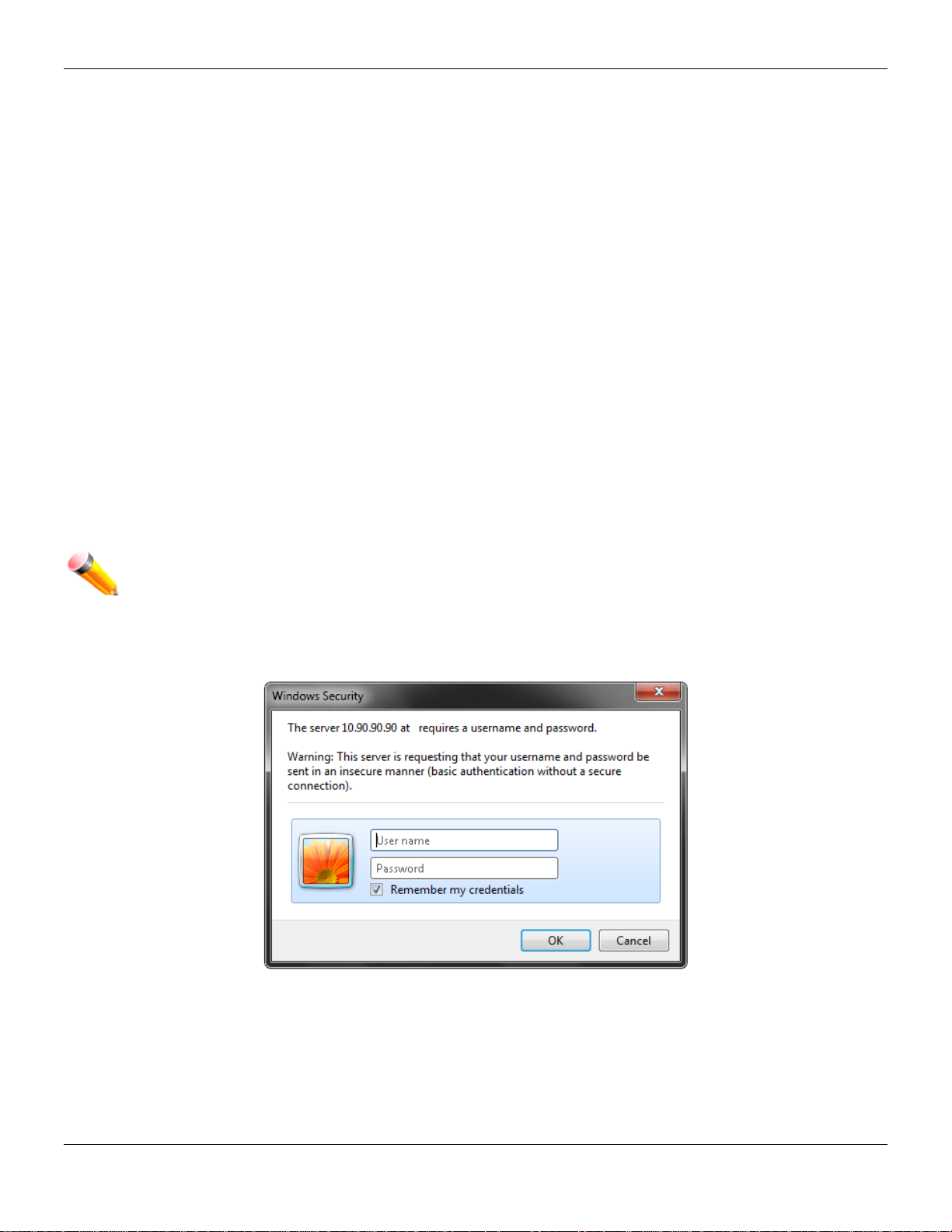
Login to the Web Manager
To begin managing the Switch, simply run the browser installed on your computer and point it to the IP address you
have defined for the device. The URL in the address bar should read something like: http://123.123.123.123, where the
numbers 123 represent the IP address of the Switch.
NOTE: The factory default IP address, for a normal port, is 10.90.90.90. The factory default IP address,
for the management port, is 192.168.0.1.
The Web User Interface’s authentication wind o w can b e accessed using the IP address of 10.90.90.90 (normal port),
as seen below.
Figure 1-1 Enter Network Password window
Leave both the User Name field and the Password field blank and click OK. This will open the Web-based user
interface. The Switch management features available in the web-based manager are explained below.
Web-based User Interface
5
Page 17
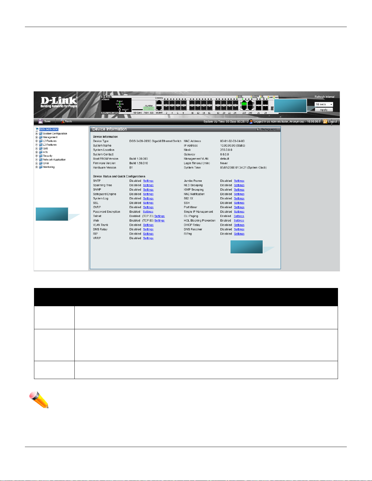
xStack® DGS-3420 Series Layer 2 Managed Stackable Gigabit Switch Web UI Reference Guide
Link website.
here.
AREA 2
AREA 1
AREA 3
The user interface provides access to various Switch configuration and management windows, allows you to view
performance statistics, and permits you to graphically monitor the system status.
Areas of the User Interface
The figure below shows the user interface. Three distinct areas divide the user interface, as described in the table.
Area
Number
Area 1
Area 2
Area 3
Function
Select the menu or window to display. Open folders and click the hyperlinked menu buttons
and subfolders contained within them to display menus. Click the D-Link logo to go to the D-
Presents a graphical near real-time image of the front panel of the Switch. This area displays
the Switch's ports, console and management port, showing port activity.
Some management functions, including save, reboot, download and upload are accessible
Presents switch information based on user selection and the entry of configuration data.
NOTE: Any changes made to the Switch configuration during the current session must be saved in the
Save Configuration / Log window or use the command line interface (CLI) command save.
Web Pages
Figure 1-2 Main Web-Manager page
6
Page 18

xStack® DGS-3420 Series Layer 2 Managed Stackable Gigabit Switch Web UI Reference Guide
When connecting to the management mode of the Switch with a web browser, a login screen is displayed. Enter a user
name and password to access the Switch's management mode.
Below is a list of the main folders available in the Web interface:
System Configuration - In this section the user will be able to configure features regarding the Switch’s configuration.
Management - In this section the user will be able to configure features regarding the Switch’s management.
L2 Features - In this section the user wil l be a ble t o co nfigure features regardin g t he Layer 2 functionality of t he S witc h.
L3 Features - In this section the user wil l be a ble t o co nfigure features regardin g t he Layer 3 functionality of t he S witc h.
QoS - In this section the user will be able to configure features regarding the Quality of Service functionality of the
Switch.
ACL - In this section the user will be able to configure features regarding the Access Control List functionality of the
Switch.
Security - In this section the user will be able to configure features regarding the Switch’s security.
Network Application - In this section the user will be able to configure features regarding network applications
handled by the Switch.
OAM - In this section the user will be able to configure features regarding the Switch’s operations, administration and
maintenance (OAM).
Monitoring - In this section the user will be able to monitor the Switch’s configuration and statistics.
NOTE: Be sure to configure the user name and password in the User Accounts menu before
connecting the Switch to the greater network.
7
Page 19

xStack® DGS-3420 Series Layer 2 Managed Stackable Gigabit Switch Web UI Reference Guide
Chapter 2 System Configuration
Device Information
System Information Settings
Port Configuration
PoE
Serial Port Settings
Warning Temperature Settings
System Log configuration
Time Range Settings
Port Group Settings
Time Settings
User Accounts Settings
Command Logging Settings
Stacking
Device Information
This window contains the main settings for all the major functions for the Switch. It appears automatically when you log
on to the Switch. To return to the Device Information window after viewing other windows, click the DGS-3420-28SC
link.
The Device Information window shows the Switch’s M AC Addr es s (ass ign ed b y the fac tor y and uncha nge ab le), the
Boot PROM Version, Firmware Version, Hardware Version, and many other important types of information. This is
helpful to keep track of PROM and firmware updates and to obtain the Switch’s MAC address for entry into another
network device’s address table, if necessary. In addition, this window displays the status of functions on the Switch to
quickly assess their current global status.
Many functions are hyper-linked for easy access to enable quick configuration from this window.
8
Page 20
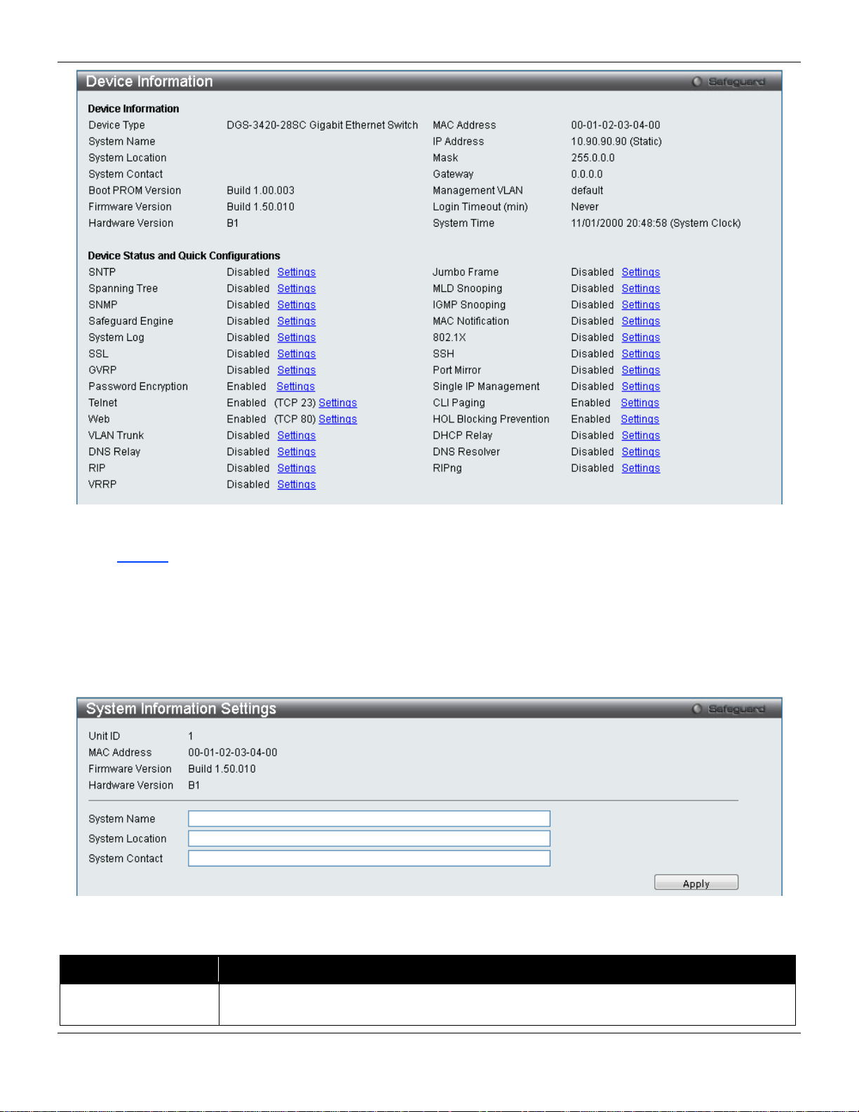
xStack® DGS-3420 Series Layer 2 Managed Stackable Gigabit Switch Web UI Reference Guide
network.
Figure 2-1 Device Information windo w
Click the Settings link to navigate to the appropriate feature page for configuration.
System Information Settings
The user can enter a System Name, System Location, and System Contact to aid in def in ing the Sw itch.
To view the following window, click System Configuration > System Information Settings, as show below:
Figure 2-2 System Information Settings window
The fields that can be configured are des cr ibed be lo w:
Parameter Description
System Name
Enter a system name for the Switch, if so desired. This name will identify it in the Switch
9
Page 21
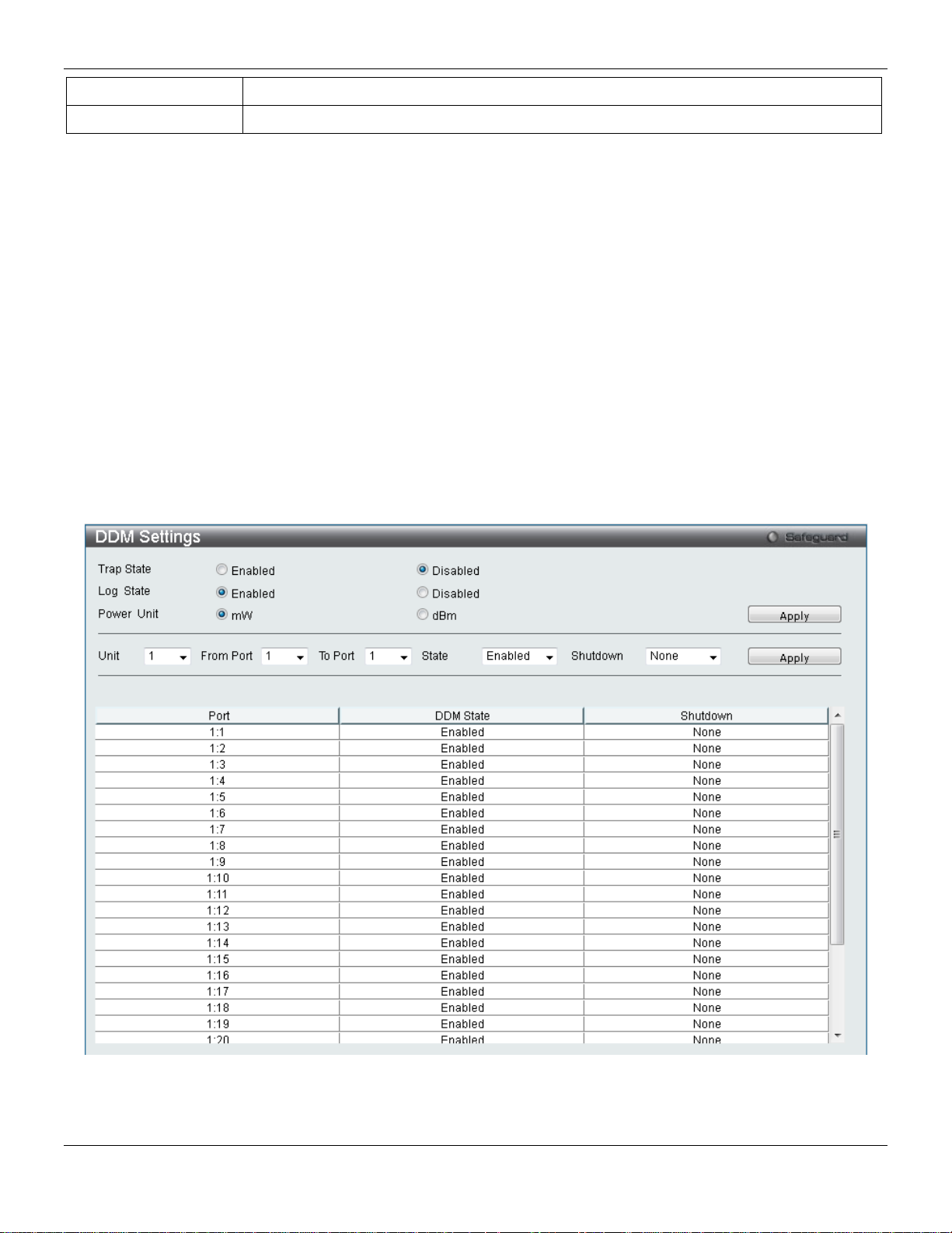
xStack® DGS-3420 Series Layer 2 Managed Stackable Gigabit Switch Web UI Reference Guide
System Location
Enter the location of the Switch, if so desired.
System Contact
Enter a contact name for the Switch, if so desired.
Click the Apply button to implement changes made.
Port Configuration
DDM
This folder contains windows that perform Digital Diagnostic Monitoring (DDM) functions on the Switch. There are
windows that allow the user to view the digital diagnostic monitoring status of SFP modules inserting to the Switch and
to configure alarm settings, warning settings, temperature threshold settings, voltage threshold settings, bias current
threshold settings, TX power threshold settings, and Rx power threshold settings.
DDM Settings
The window is used to configure the action that will occur for specific ports when an exceeding alarm threshold or
warning threshold event is encountered.
To view the following window, click System Configuration > Port Configuration > DDM > DDM Settings, as show
below:
The fields that can be configured are described below:
Figure 2-3 DDM Settings window
10
Page 22
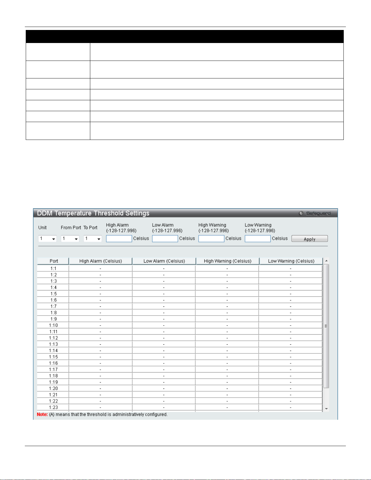
xStack® DGS-3420 Series Layer 2 Managed Stackable Gigabit Switch Web UI Reference Guide
warning threshold.
warning threshold.
Power Unit
Select the power unit used here. Options to choose from are mW and dBm.
Unit
Select the unit to be configured.
From Port / To Port
Select a range of ports to be configured.
State
Use the drop-down menu to enable or disable the DDM state
or Warning threshold.
Parameter Description
Trap State
Log State
Shutdown Specifies whether to shutdown the port, when the operating parameter exceeds the Alarm
Click the Apply button to accept the changes made for each individual section.
Specify whether to send the trap, when the operating parameter exceeds the alarm or
Specify whether to send the log, when the operating parameter exceeds the alarm or
DDM Temperature Threshold Settings
This window is used to configure the DDM Temperature Threshold Settings for specific ports on the Switch.
To view the following window, click System Configuration > Port Configuration > DD M > DDM Temperature
Threshold Settings, as show below:
Figure 2-4 DDM Temperature Threshold Settings window
11
Page 23
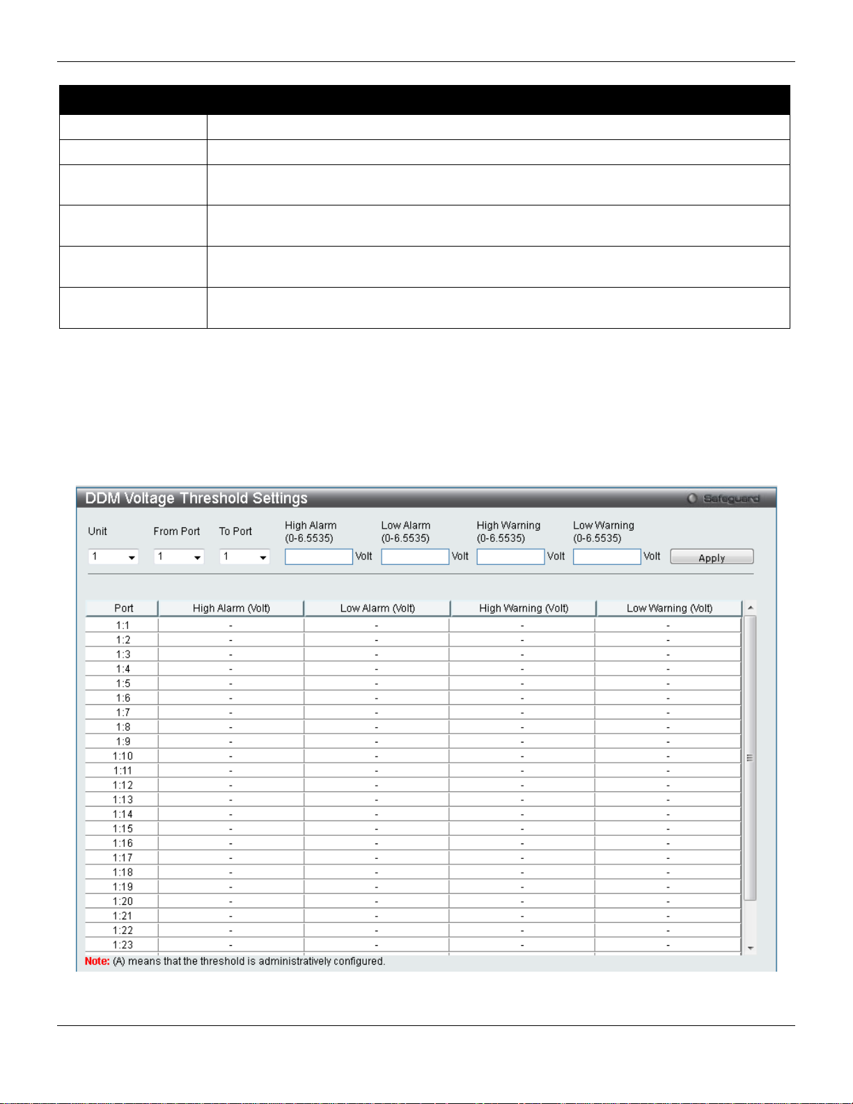
xStack® DGS-3420 Series Layer 2 Managed Stackable Gigabit Switch Web UI Reference Guide
Unit
Select the unit to be configured.
From Port / To Port
Select a range of ports to be configured.
127.996)
value, action associated with the alarm will be taken.
127.996)
value, action associated with the alarm will be taken.
127.996)
this value, action associated with the war nin g wil l be taken.
127.996)
value, action associated with the warning will be taken.
The fields that can be configured are described below:
Parameter Description
High Alarm (-128-
Low Alarm (-128-
High Warning (-128-
Low Warning (-128-
Click the Apply button to accept the changes made.
This is the highest threshold for the alarm. When the operating parameter rises above this
This is the lowest threshold for the alarm. When the operating parameter falls below this
This is the highest threshold for the warning. When the operating parameter rises above
This is the lowest threshold for the warning. When the operating parameter falls below this
DDM Voltage Threshold Settings
This window is used to configure the DDM Voltage Threshold Settings for specific ports on the Switch.
To view the following window, click System Configuration > Port Configuration > DD M > DDM Voltag e Threshold
Settings, as show below:
Figure 2-5 DDM Voltage Threshold Settings windo w
12
Page 24
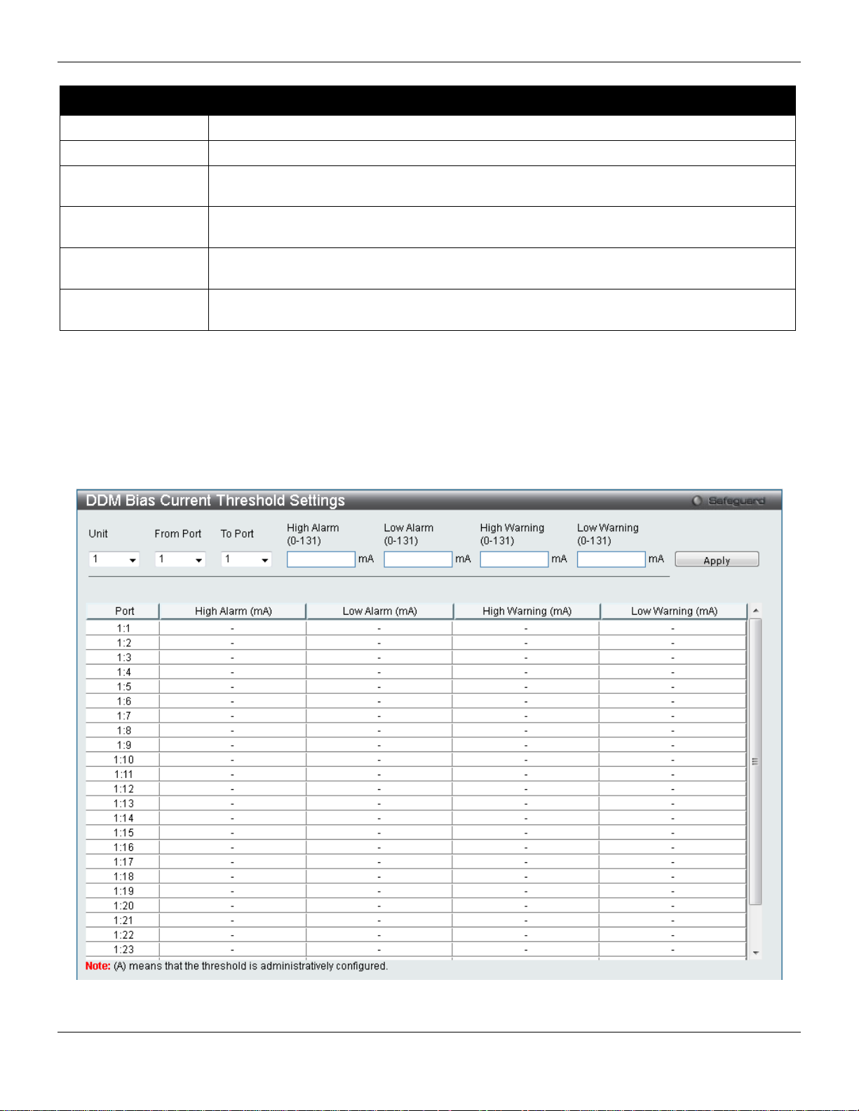
xStack® DGS-3420 Series Layer 2 Managed Stackable Gigabit Switch Web UI Reference Guide
Unit
Select the unit to be configured.
From Port / To Port
Select a range of ports to be configured.
6.5535)
value, action associated with the alarm will be taken.
6.5535)
value, action associated with the alarm will be taken.
6.5535)
this value, action associated with the war nin g wil l be taken.
6.5535)
value, action associated with the warning will be taken.
The fields that can be configured are described below:
Parameter Description
High Alarm (0-
Low Alarm (0-
High Warning (0-
Low Warning (0-
Click the Apply button to accept the changes made.
This is the highest threshold for the alarm. When the operating parameter rises above this
This is the lowest threshold for the alarm. When the operating parameter falls below this
This is the highest threshold for the warning. When the operating parameter rises above
This is the lowest threshold for the warning. When the operating parameter falls below this
DDM Bias Current Threshold Settings
This window is used to configure the threshold of the bias current for specific ports on the Switch.
To view the following window, click System Configuration > Port Configuration > DD M > DDM Bias Current
Threshold Settings, as show below:
Figure 2-6 DDM Bias Current Threshold Settings window
13
Page 25

xStack® DGS-3420 Series Layer 2 Managed Stackable Gigabit Switch Web UI Reference Guide
Unit
Select the unit to be configured.
From Port / To Port
Select a range of ports to be configured.
this value, action associated with the alarm will be taken.
value, action associated with the alarm will be taken.
this value, action associated with the war nin g wil l be taken.
this value, action associated with the war nin g wil l be taken.
The fields that can be configured are described below:
Parameter Description
High Alarm (0-131)
Low Alarm (0-131)
High Warning (0-131)
Low Warning (0-131)
Click the Apply button to accept the changes made.
This is the highest threshold for the alarm. When the operating parameter rises above
This is the lowest threshold for the alarm. When the operating parameter falls below this
This is the highest threshold for the warning. When the operating parameter rises above
This is the lowest threshold for the warning. When the operating parameter falls below
DDM TX Power Threshold Settings
This window is used to configure the threshold of TX power for specific ports on the Switch.
To view the following window, click System Configuration > Port Configuration > DD M > DDM TX Power
Threshold Settings, as show below:
Figure 2-7 DDM TX Power Threshold Settings window
14
Page 26
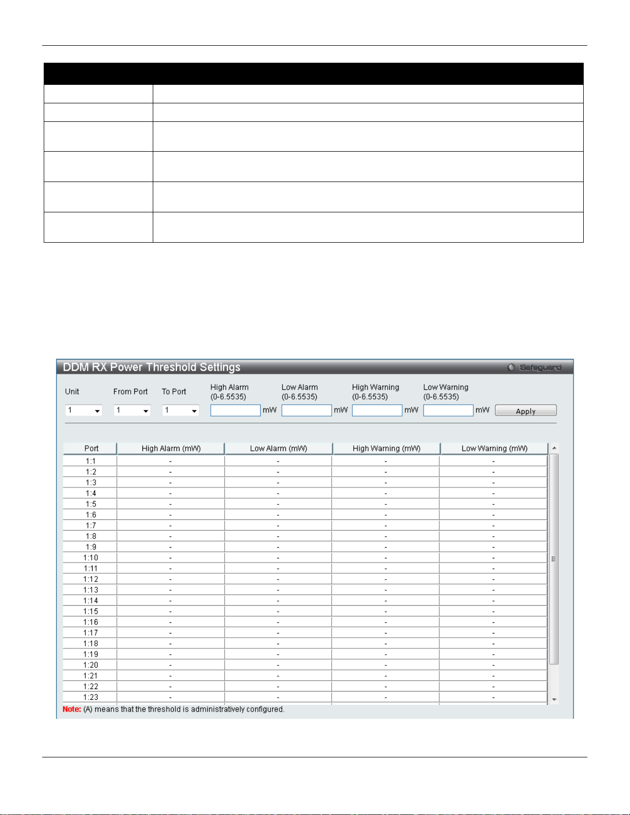
xStack® DGS-3420 Series Layer 2 Managed Stackable Gigabit Switch Web UI Reference Guide
Unit
Select the unit to be configured.
From Port / To Port
Select a range of ports to be configured.
6.5535)
value, action associated with the alarm will be taken.
6.5535)
value, action associated with the alarm will be taken.
6.5535)
this value, action associated with the war nin g wil l be taken.
6.5535)
value, action associated with the warning will be taken.
The fields that can be configured are described below:
Parameter Description
High Alarm (0-
Low Alarm (0-
High Warning (0-
Low Warning (0-
Click the Apply button to accept the changes made.
This is the highest threshold for the alarm. When the operating parameter rises above this
This is the lowest threshold for the alarm. When the operating parameter falls below this
This is the highest threshold for the warning. When the operating parameter rises above
This is the lowest threshold for the warning. When the operating parameter falls below this
DDM RX Power Threshold Settings
This window is used to configure the threshold of RX power for specific ports on the Switch.
To view the following window, click System Configuration > Port Configuration > DD M > DDM RX Power
Threshold Settings, as show below:
Figure 2-8 DDM RX Power Threshold Settings window
15
Page 27
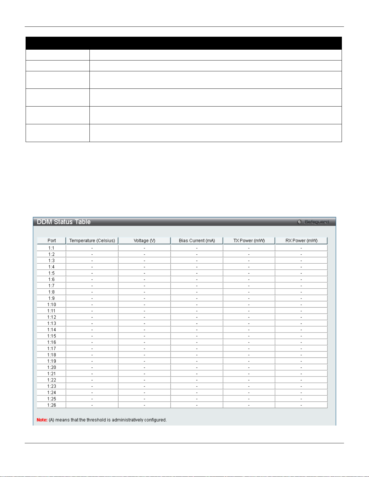
xStack® DGS-3420 Series Layer 2 Managed Stackable Gigabit Switch Web UI Reference Guide
Unit
Select the unit to be configured.
From Port / To Port
Select a range of ports to be configured.
6.5535)
value, action associated with the alarm will be taken.
6.5535)
value, action associated with the alarm will be taken.
6.5535)
this value, action associated with the war nin g wil l be taken.
6.5535)
value, action associated with the warning will be taken.
The fields that can be configured are described below:
Parameter Description
High Alarm (0-
Low Alarm (0-
High Warning (0-
Low Warning (0-
Click the Apply button to accept the changes made.
This is the highest threshold for the alarm. When the operating parameter rises above this
This is the lowest threshold for the alarm. When the operating parameter falls below this
This is the highest threshold for the warning. When the operating parameter rises above
This is the lowest threshold for the warning. When the operating parameter falls below this
DDM Status Table
This window is used to display the current operating digital diagnostic monitoring parameters and their values on the
SFP module for specified ports.
To view the following window, click System Configuration > Port Configuration > DD M > DDM Status Tabl e, as
show below:
Figure 2-9 DDM Status Table window
16
Page 28
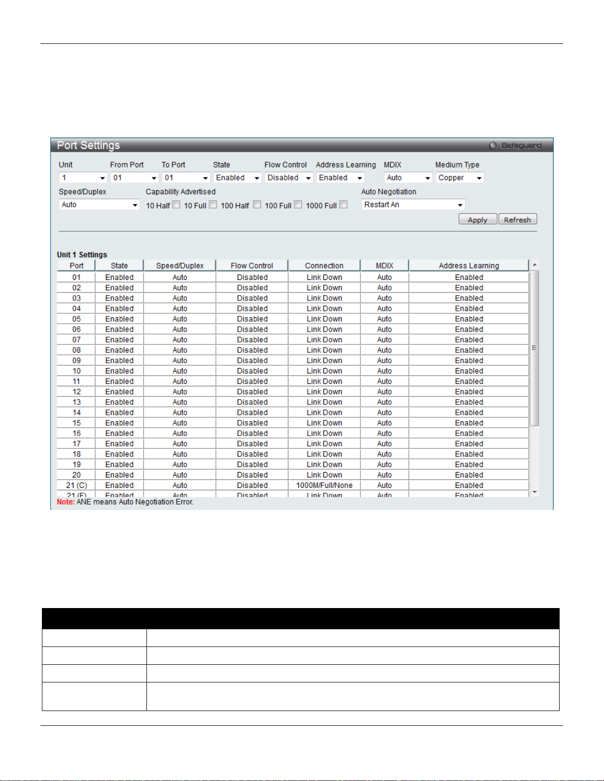
xStack® DGS-3420 Series Layer 2 Managed Stackable Gigabit Switch Web UI Reference Guide
Unit
Select the unit you wish to configure.
From Port / To Port
Select the appropriate port range used for the configuration here.
State
Toggle the State field to either enable or disable a given port or group of ports.
Full, 1000M Full_Master and 1000M Full_Slave. Auto denotes auto-negotiation among 10,
Port Settings
This page used to configure the details of the switch ports.
To view the following window, click System Configuration > Port Configuration > Port Settings, as show below:
Figure 2-10 Port Settings window
To configure switch ports:
1. Choose the port or sequential range of ports using the From Port and To Port drop-down menus.
2. Use the remaining drop-down menus to configure the parameters described below:
The fields that can be configured are described below:
Parameter Description
Speed/Duplex Use the drop-down menu to select the speed in Auto, 10M Half, 10M Full, 100M Half, 100M
17
Page 29

xStack® DGS-3420 Series Layer 2 Managed Stackable Gigabit Switch Web UI Reference Guide
100 and 1000 Mbps devices, in full- or half-duplex (except 1000 Mbps which is always full
down status for both ports.
Advertised
negotiation.
Auto ports use an automatic selection of the two. The default is Disabled.
Connection
Here the current connection speed will be displayed.
can be connected to a port (in MDI mode) on another switch through a straight cable.
The default setting is Enabled.
Medium Type
If configuring the Combo ports, this defines the type of transport medium to be used.
Remote Fault Advertisedt - The remote fault advertisement option will be configured.
duplex). The Auto setting allows the port to automatically determine the fastest settings the
device the port is connected to can handle, and then to use those settings. The other
options are 10M Half, 10M Full, 100M Half, 100M Full, 1000M Full_Master, 1000M
Full_Slave, and 1000M Full. There is no automatic adjustment of port settings with any
option other than Auto.
The Switch allows the user to configure two types of gigabit connections; 1000M
Full_Master, and 1000M Full_Slave which refer to connections running a 1000BASE-T
cable for connection between the Switch port and other device capable of a gigabit
connection. The master setting (1000M Full_Master) will allow the port to advertise
capabilities related to duplex, speed and physical layer type. The master sett ing will also
determine the master and slave relationship between the two connected physical layers.
This relationship is necessary for establishing the timing control between the two physical
layers. The timing control is set on a master physical layer by a local source. The slave
setting (1000M Full_Slave) uses loop timing, where the timing comes from a data stream
received from the master. If one connection is set for 1000M Full_Master, the other side of
the connection must be set for 1000M Full_Slave. Any other configuration will result in a link
Capability
Flow Control
MDIX Auto - Select auto for auto sensing of the optimal type of cabling.
Address Learning Enable or disable MAC address learning for the selected ports. When Enabled, destina tio n
Auto Negotiation
When the Speed/Duplex is set to Auto, these capabilities are advertised during auto
Displays the flow control scheme used for the various port configurations. Ports configured
for full-duplex use 802.3x flow control, half-duplex ports use backpressure flow control, and
Normal - Select normal for normal cabling. If set to normal state, the port is in MDI mode
and can be connected to a PC NIC using a straight-through cable or a port (in MDI mode)
on another switch through a cross-over cable.
Cross - Select cross for cross cabling. If set to cross state, the port is in MDIX mode, and
and source MAC addresses are automatically listed in the forwarding table. When address
learning is Disabled, MAC addresses must be manually entered into the forwarding table.
This is sometimes done for reasons of security or efficiency. See the section on
Forwarding/Filtering for information on entering MAC addresses into the forwarding table.
Use the drop-down menu to specify the auto-negotiation configuration.
Restart An – Select to restart the auto-negotiation process
Click the Apply button to implement changes made.
Click the Refresh button to refresh the display section of this page.
Port Description Settings
The Switch supports a port description feature where the user may name various ports.
To view the following window, click System Configuration > Port Configuration > Port Description Settings, as
show below:
18
Page 30
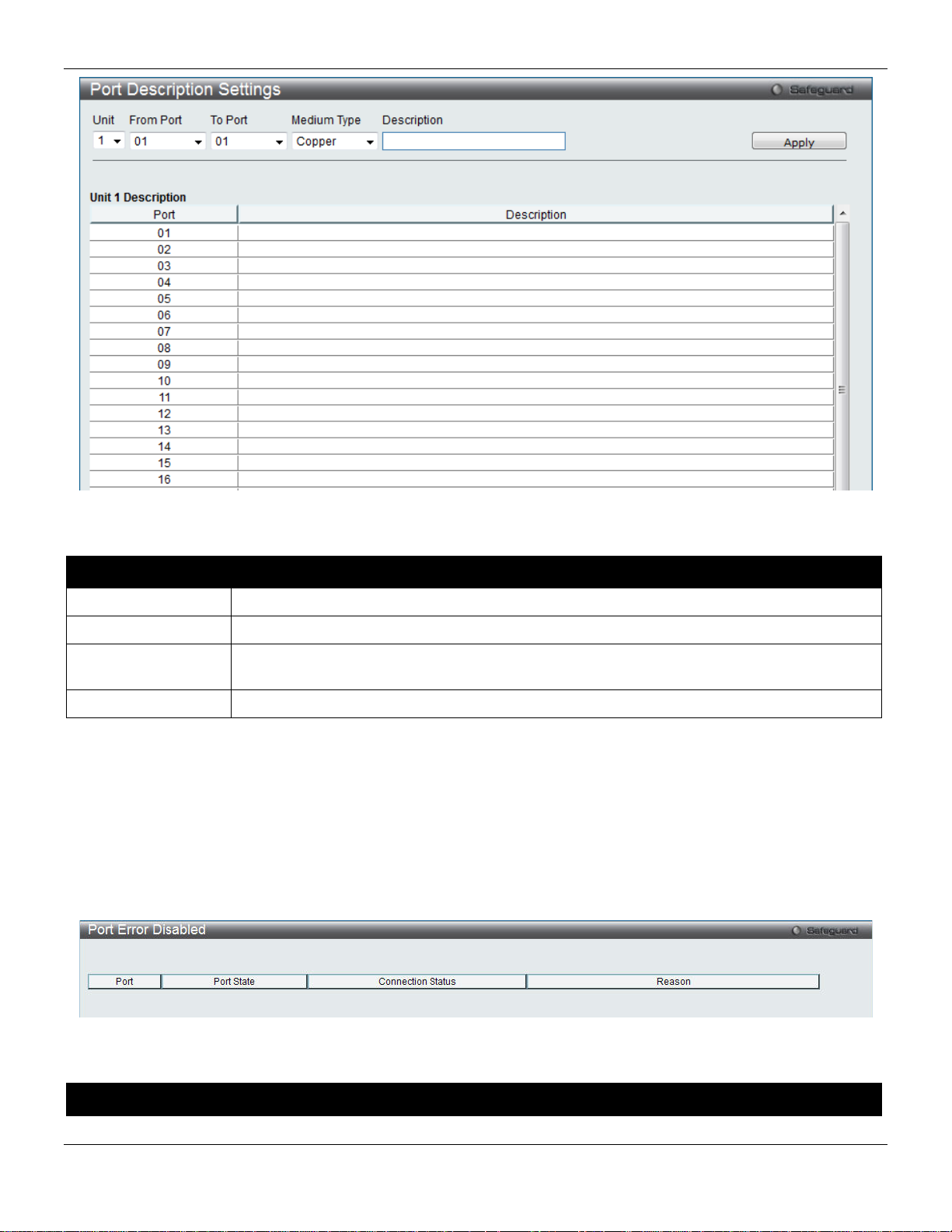
xStack® DGS-3420 Series Layer 2 Managed Stackable Gigabit Switch Web UI Reference Guide
Unit
Select the unit you wish to configure.
From Port / To Port
Select the appropriate port range used for the configuration here.
Type defines the type of transport medium to be used, whether Copper or Fiber.
Description
Users may then enter a description for the chosen port(s).
Figure 2-11 Port Description Settings window
The fields that can be configured are described below:
Parameter Description
Medium Type
Click the Apply button to implement changes made.
Specify the medium type for the selected ports. If configuring the Combo ports, the Medium
Port Error Disabled
The following window displays the information about ports that have been disconnected by the Switch when a packet
storm occurs or a loop was detected.
To view the following window, click System Configuration > Port Configuration > Port Error Disabled, as show
below:
Figure 2-12 Port Error Disabled
The fields that can be displayed are described below:
Parameter Description
19
Page 31

xStack® DGS-3420 Series Layer 2 Managed Stackable Gigabit Switch Web UI Reference Guide
Port
Display the port that has been error disabled.
Port State
Describe the current running state of the port, whether enabled or disabled.
Connection Status
Display the uplink status of the individual ports, whether enabled or disabled.
shutdown port for storm control.
Unit
Select the unit you wish to configure.
Port
Display the port number.
Type
Displays the port media type.
Reason
Describe the reason why the port has been error-disabled, such as it has become a
Port Media Type
The following window displays the information about the port media type.
To view the following window, click System Configuration > Port Configuration > Port Media Type, as show below:
Figure 2-13 Port Media Type window
The fields that can be displayed are described below:
Parameter Description
Port Auto Negotiation Information
20
Page 32

xStack® DGS-3420 Series Layer 2 Managed Stackable Gigabit Switch Web UI Reference Guide
Unit
Select the unit you wish to configure.
The following window displays the detailed auto negotiation information.
To view the following window, click System Configuration > Port Configuration > Port Auto Negotiation
Information, as show below:
Figure 2-14 Port Auto Negotiation Information window
The fields that can be displayed are described below:
Parameter Description
Jumbo Frame Settings
The Switch supports jumbo frames. Jumbo frames are Ethernet frames with more than 1,518 bytes of payload. The
Switch supports jumbo frames with a maximum frame size of up to 13,312 bytes.
To view the following window, click System Configuration > Port Configuration > Jumbo Frame Settings, as show
below:
21
Page 33

xStack® DGS-3420 Series Layer 2 Managed Stackable Gigabit Switch Web UI Reference Guide
Unit
Select the unit you wish to configure.
the maximum frame size is 13312 bytes.
From Port / To Port
Select the appropriate port range used for the configuration here.
State
Use the drop-down menu to enable the Jumbo Frame for the port.
Figure 2-15 Jumbo Frame Settings window
The fields that can be configured are described below:
Parameter Description
Jumbo Frame
Click the Apply button to implement changes made.
Use the radio buttons to enable or disable the Jumbo Frame function on the Switch. The
default is Disabled. When disabled, the maximum frame size is 1536 bytes. When enabled,
EEE Settings
Energy Efficient Ethernet (EEE) is defined in IEEE 802.3az. It is designed to reduce the energy consumption of a link
when no packets are being sent.
NOTE: This feature is only available on hardware version B1 and later.
To view the following window, click System Configuration > Port Configuration > EEE Settings, as show below:
22
Page 34

xStack® DGS-3420 Series Layer 2 Managed Stackable Gigabit Switch Web UI Reference Guide
Unit
Select the unit you wish to configure.
From Port / To Port
Select the appropriate port range used for the configuration here.
State
Select to enable or disable the state of this feature here.
Figure 2-16 EEE Settings window
The fields that can be configured are described below:
Parameter Description
Click the Apply button to implement changes made.
PoE
The DGS-3420-28PC and DGS-3420-52P switches support Power over Ethernet (PoE) as defined by the IEEE 802.3af
and 802.3at. All ports can support PoE up to 30W. All the ports can supply about 48 VDC power to Powered Devices
(PDs) over Category 5 or Category 3 UTP Ethernet cables. The Switch follows the standar d PSE (Power Sourcing
Equipment) pinout Alternative A, whereby power is sent out over pins 1, 2, 3 and 6. The Switches work with all D-Link
802.3af capable devices.
The Switch includes the following PoE features:
• Auto-discovery recognizes the connection of a PD (Powered Device) and automatically sends power to it.
23
Page 35

xStack® DGS-3420 Series Layer 2 Managed Stackable Gigabit Switch Web UI Reference Guide
• The Auto-disable feature occurs under two conditions: firstly, if the total power consumption exceeds the
system power limit; and secondly, if the per port power consumption exceeds the per port power limit.
• Active circuit protection automatically disables the port if there is a short. Other ports will remain active.
Based on 802.3af/at PDs receive power according to
the following classification:
Class Maximum power available to PD Class Max. power used by PSE
0 12.95W 0 15.4W
1 3.84W 1 4W
2 6.49W 2 7W
3 12.95W 3 15.4W
4 29.5W User Define 35W
To configure the PoE features on the Switch, click System Configuration > PoE. The PoE System Settings window
is used to assign a power limit and power disconnect method for the whole PoE system. To configure the Power Limit
for the PoE system, enter a value between 37W and 760W for the Switch in the Power Limit field. When the total
consumed power exceeds the power limit, the PoE controller (located in the PSE) disconnects the power to prevent
overloading the power supply.
PSE provides power according to the foll o wing
classification:
PoE System Settings
To view the following window, click System Configuration > PoE > PoE System Settings, as show below:
24
Page 36

xStack® DGS-3420 Series Layer 2 Managed Stackable Gigabit Switch Web UI Reference Guide
Unit
Select the unit you wish to configure. Tick the All check box to select all units.
3420-52P.
priority and critical priority ports to power up.
Legacy PD
Use the drop-down menu to enable or disable detecting legacy PDs signal.
Limit must be set to 760W.
Figure 2-17 PoE System Settings window
The following parameters can be configured:
Parameter Description
Power Limit (37-
760)
Power Disconnect
Method
Sets the limit of power to be used from the Switch’s power source to PoE ports. The user
may configure a Power Limit between 37W and 760W for the DGS-3420-28PC and DGS-
The PoE controller uses either Deny Next Port or Deny Low Priority Port to offset the power
limit being exceeded and keeps the Switch’s power at a usable level. Use the drop down
menu to select a Power Disconnect Method. The default Power Disconnect Method is
Deny Next Port. Both Power Disconnection Methods are described below:
Deny Next Port – After the power limit has been exceeded, the next port attempting to
power up is denied, regardless of its priority. If Power Disconnection Method is set to Deny
Next Port, the system cannot utilize out of its maximum power capacity. The maximum
unused watt is 19W.
Deny Low Priority Port – After the power limit has been exceeded, the next port attempting
to power up causes the port with the lowest priority to shut down so as to allow the high-
Click Apply to implement changes made.
NOTE: The Power Limit for this Switch without a Redundant Power Supply (RPS) is 390W. When the
user adds an RPS, like the DPS-700, for the DGS-3420-28PC and the DGS-3420-52P, the Po w er
25
Page 37

xStack® DGS-3420 Series Layer 2 Managed Stackable Gigabit Switch Web UI Reference Guide
Unit
Select the unit you wish to configure.
From Port / To Port
Select a range of ports from the drop-down menus to be enabled or disabled for PoE.
State
Use the drop-down menu to enable or disable ports for PoE.
can only be supplied during the specified period of time.
by the system to manage the supply of power to ports.
User Define – 35000mW
PoE Port Settings
To view the following window, click System Configuration > PoE > PoE Port Settings, as show below:
Figure 2-18 PoE Port Settings window
The following parameters can be configured:
Parameter Description
Time Range
Priority
Power Limit
Select a range of the time to the port set as POE. If Time Range is configured, the power
Use the drop-down menu to select the priority of the PoE ports. Port priority determines the
priority which the system attempts to supply the power to the ports. There are three levels of
priority that can be selected, Critical, High, and Low. When multiple ports happen to have
the same level of priority, the port ID will be used to determine the priority. The lower port ID
has higher priority. The setting of priority will affect the order of supplying power. Whether
the disconnect method is set to deny low priority port, the priority of each port will be use d
This function is used to configure the per-port power limit. If a port exceeds its power limit, it
will shut down.
Based on 802.3af/802.3at, there are different PD classes and power cons umption ranges;
Class 0 – 0.44~12.95W
Class 1 – 0.44~3.84W
Class 2 – 3.84~6.49W
Class 3 – 6.49~12.95W
Class 4 – 29.5W
The following is the power limit applied to the port for these five classes. For each class, the
power limit is a little more than the power consumption range for that class. This takes into
account any power loss on the cable. Thus, the following are the typical values;
Class 0 – 15400mW
Class 1 – 4000mW
Class 2 – 7000mW
Class 3 – 15400mW
Click Apply to implement changes made. The port status of all PoE configured ports is displayed in the table in the
bottom half of the screen shown above.
26
Page 38

xStack® DGS-3420 Series Layer 2 Managed Stackable Gigabit Switch Web UI Reference Guide
port, the baud rate must be set to 115200, which is the default setting.
Never. The default setting is 10 minutes.
Data Bits
Display the data bits used for the serial port connection.
Parity Bits
Display the parity bits used for the serial port connection.
Stop Bits
Display the stop bits used for the serial port connection.
Serial Port Settings
This window allows the user to adjust the Baud Rate and the Auto Logout values.
To view the following window, click System Configuration > Serial Port Settings, as show below:
Figure 2-19 Serial Port Settings window
The fields that can be configured are described below:
Parameter Description
Baud Rate
Auto Logout
Click the Apply button to implement changes made.
Specify the baud rate for the serial port on the Switch. There are four possible baud rates to
choose from, 9600, 19200, 38400 and 115200. For a connection to the Switch using the console
Select the logout time used for the console interface. This automatically logs the user out after
an idle period of time, as defined. Choose from the following options: 2, 5, 10, 15 minutes or
Warning Temperature Settings
This window allows the user to configure the system warning temperature parameters.
To view the following window, click System Configuration > Warning Temperature Setting s, as show below:
Figure 2-20 Warning Temperature Settings window
The fields that can be configured are described below:
27
Page 39

xStack® DGS-3420 Series Layer 2 Managed Stackable Gigabit Switch Web UI Reference Guide
setting.
setting.
(-500-500)
(-500-500)
accept the changes made.
log event occurs on the Switch.
Parameter Description
Traps State
Log State
High Threshold
Low Threshold
Click the Apply button to implement changes made.
Use the drop-down menu to enable or disable the traps state option of the warning temperature
Use the drop-down menu to enable or disable the log state opt ion of th e warnin g temperature
Enter the high threshold value of the warning temperature setting.
Enter the low threshold value of the warning temperature setting.
System Log configuration
System Log Settings
The Switch allows users to choose a method for which to save the switch log to the flash memory of the Switch.
To view the following window, click System Configuration > System Log Configuration > System Log Settings, as
show below:
Figure 2-21 System Log Settings window
The fields that can be configured are described below:
Parameter Description
System Log Use the radio buttons to enable or disable the system log settings. Click the Apply button to
Save Mode
Click the Apply button to implement changes made.
Use the drop-down menu to choose the method for saving the switch log to the flash memory.
The user has three options:
On Demand – Users who choose this method will only save log files when they manually tell the
Switch to do so, either using the Save Log link in the Save folder.
Time Interval – Users who choose this method can configure a time interval by which the Switch
will save the log files, in the box adjacent to this configuration field. The user may set a time
between 1 and 65535 minutes.
Log Trigger – Users who choose this method will have log files saved to the Switch every time a
System Log Server Settings
28
Page 40

xStack® DGS-3420 Series Layer 2 Managed Stackable Gigabit Switch Web UI Reference Guide
Server ID
System log server settings index (1 to 4).
Debug(7).
Server IPv4 Address
The IPv4 address of the System log server.
Server IPv6 Address
The IPv6 address of the System log server.
Local 6, or Local 7.
(514 or 6000-65535)
Status
Choose Enabled or Disabled to activate or deactivate.
The Switch can send System log messages to up to four designated servers using the System Log Server.
To view the following window, click System Configuration > System Log Configuration > System Log Server
Settings, as show below:
Figure 2-22 System Log Server Settings
The fields that can be configured are described below:
Parameter Description
Severity
Facility Use the drop-down menu to select Local 0, Local 1, Local 2, Local 3, Local 4, Local 5,
UDP Port
Click the Apply button to accept the changes made.
Click the Delet e All button to remove all servers configured.
Use the drop-down menu to select the higher level of messages that will be sent. All
messages which level is higher than selecting level will be sent. The options are
Emergency(0), Alert(1), Critical(2), Error(3), Warning(4), Notice(5), Informational(6) and
Type the UDP port number used for sending System log messages. The default is 514.
System Log
Users can view and delete the local history log as compiled b y the Switch's m anagement agent.
To view the following window, click System Configuration > System Log Configuration > System Log, as show
below:
29
Page 41

xStack® DGS-3420 Series Layer 2 Managed Stackable Gigabit Switch Web UI Reference Guide
down menu to display the result of the unit.
the last entry (highest sequence number) first.
Time
Display the time in days, hours, minutes, and seconds since the Switch was last restarted.
Level
Display the level of the log entry.
Log Text
Display text describing the event that triggered the history log entry.
Figure 2-23 System Log window
The Switch can record event information in its own log. Click Go to go to the next page of the System Log window.
The fields that can be configured or displayed are described below:
Parameter Description
Log Type
Index
Click the Find button to display the log in the display section according to the selection made.
Click the Clear Log button to clear the entries from the log in the display section.
Click the Clear Attack Log button to clear the entries from the attack log in the display section.
Enter a page number and click the Go button to navigate to a specific page when multiple pages exist.
In the drop-down menu the user can select the log type that will be displayed.
Severity - When selecting Severity from the drop-down menu, a secondary tick must be made.
Secondary ticks are Emergency, Alert, Critical, Error, Warning, Notice, Informational and
Debug. To view all information in the log, simply tick the All check box. Enter the module name
to search for the specific module.
Module List - When selecting Module List, the module name must be manually entered.
Available modules are MSTP, DHCPv6_CLIENT, DHCPv6_RELAY, ERPS, ERROR_LOG,
CFM_EXT, and DHCPv6_SERVER.
Attack Log - When selecting Attack Log all attacks will be listed. Select a unit from the drop-
A counter incremented whenever an entry to the Switch's history log is made. The table displays
System Log & Trap Settings
The Switch allows users to configure the system log source IP interface addresses here.
To view the following window, click System Configuration > System Log Configuration > System Log & Trap
Settings, as show below:
30
Page 42
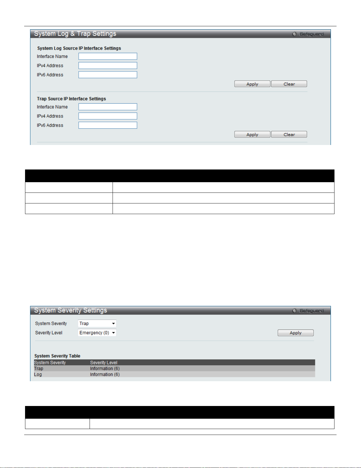
xStack® DGS-3420 Series Layer 2 Managed Stackable Gigabit Switch Web UI Reference Guide
Interface Name
Enter the IP interface name used.
IPv4 Address
Enter the IPv4 address used.
IPv6 Address
Enter the IPv6 address used.
System Severity
Choose how the alerts are used from the drop-down menu. Select Log to send the alert of
Figure 2-24 System Log & Trap Settings window
The fields that can be configured are described below:
Parameter Description
Click the Apply button to accept the changes made.
Click the Clear button to clear all the information entered in the fields.
System Severity Settings
The Switch can be configured to allow alerts be logged or sent as a trap to an SNMP agent. The level at which the alert
triggers either a log entry or a trap message can be set as well. Use the System Severity Settings window to set the
criteria for alerts. The current settings are displayed below the System Severity Table.
To view the following window, click System Configuration > System Log Configuration > System Severity
Settings, as show below:
Figure 2-25 System Severity Settings window
The fields that can be configured are described below:
Parameter Description
31
Page 43

xStack® DGS-3420 Series Layer 2 Managed Stackable Gigabit Switch Web UI Reference Guide
the Severity Type configured to the Switch’s log for analysis. Choose Trap to send it to an
the Switch’s log for analysis.
Information (6) and Debug (7).
identify the access profile and associated rule to be enabled during this time range.
minutes and seconds, based on the 24-hour time system.
the week.
SNMP agent for analysis, or select All to send the chosen alert type to an SNMP agent and
Severity Level
Click the Apply button to accept the changes made.
This drop-down menu allows you to select the level of messages that will be sent. The
options are Emergency (0), Alert (1), Critical (2), Error (3), Warning (4), Notice (5),
Time Range Settings
Time range is a time period that the respective function will take an effect on, such as ACL. For example, the
administrator can configure the time-based ACL to allow users to surf the Internet on every Saturday and every
Sunday, meanwhile to deny users to surf the Internet on weekdays.
The user may enter up to 64 time range entries on the Switch.
To view the following window, click System Configuration > Time Range Settings, as show below:
Figure 2-26 Time Range Settings window
The fields that can be configured are described below:
Parameter Description
Range Name
Hours (HH MM SS)
Weekdays
Click the Apply button to accept the changes made. Current conf igur ed entr ies will be displ a yed in the Ti me Ran ge
Information table in the bottom half of the window shown above.
Enter a name of no more than 32 alphanumeric characters that will be used to identify this
time range on the Switch. This range name will be used in the Access Profile table to
This parameter is used to set the time in the day that this time range is to be enabled using
the following parameters:
Start Time - Use this parameter to identify the starting time of the time range, in hours,
minutes and seconds, based on the 24-hour time system.
End Time - Use this parameter to identify the ending time of the time range, in hours,
Use the check boxes to select the corresponding days of the week that this time range is to
be enabled. Tick the Select All Days check box to configure this time range for every day of
Port Group Settings
This window is used to create port groups, and add or delete ports from the port groups.
To view the following window, click System Configuration > Port Group Settings, as show below:
32
Page 44

xStack® DGS-3420 Series Layer 2 Managed Stackable Gigabit Switch Web UI Reference Guide
Group Name
Enter the name of a port group.
Group ID (1-64)
Enter the ID of a port group
Port List
Enter a port or list of ports. Tick the All check box to apply to all ports.
Action
Use the drop-down menu to select Create Port Group, Add Ports or Delete Ports.
Date (DD/MM/YYYY)
Enter the current day, month, and year to update the system clock.
Time (HH:MM:SS)
Enter the current time in hours, minutes, and seconds.
Figure 2-27 Port Group Settings window
The fields that can be configured are described below:
Parameter
Click the Apply button to accept the changes made.
Click the Delete button to remove the specific entry.
Description
Time Settings
Users can configure the time settings for the Switch.
To view the following window, click System Configuration > Time Settings, as show below:
Figure 2-28 Time Settings window
The fields that can be configured are described below:
Parameter Description
Click the Apply button to accept the changes made.
User Accounts Settings
The Switch allows the control of user privileges.
To view the following window, click System Configuration > User Accounts Settings, as show below:
33
Page 45

xStack® DGS-3420 Series Layer 2 Managed Stackable Gigabit Switch Web UI Reference Guide
Management
Admin
Operator
Power User
User
partly
partly
Network Monitoring
Read/Write
Read/Write
Read-only
Read-only
Stations
Files
System Utilities
Read/Write
Read-only
Read-only
Read-only
Factory Reset
Read/Write
No
No
No
User Account Management
Add/Update/Delete User Accounts
Read/Write
No
No
No
View User Accounts
Read/Write
No
No
No
User Name
Enter a new user name for the Switch.
Access Right
Specify the access right for this user.
Text, and SHA-1.
Password
Enter a new password for the Switch.
Confirm Password
Re-type in a new password for the Switch.
Figure 2-29 User Accounts Settings window
To add a new user, type in a User Name and New Password and retype the same password in the Confirm New
Password field. Choose the level of privilege (Admin, Operator, Power User or User) from the Access Right drop-down
menu.
Configuration Read/Write Read/Write–
Community Strings and Trap
Update Firmware and Configurati on
Read/Write Read-only Read-only Read-only
Read/Write No No No
Read/Write–
No
The fields that can be configured are described below:
Parameter Description
Encryption Specifies that encryption will be applied to this account. Option to choose from are Plain
Click the Apply button to accept the changes made.
NOTICE: In case of lost passwords or password corruption, refer to Appendix A - Password Recovery
Procedure which will guide you through the steps necessary to resolve this issue.
34
Page 46

xStack® DGS-3420 Series Layer 2 Managed Stackable Gigabit Switch Web UI Reference Guide
Command Logging State
Use the radio buttons to enable or disable the function.
its privilege.
NOTE: User Name should be less than 16 characters. Password should be less than 16 or 35 characters.
Command Logging Settings
This window is used to enable or disable the command logging settings.
To view this window, click System Configuration > Command Logging Settings, as shown below:
Figure 2-30 Command Logging Settings window
The fields that can be configured are described below:
Parameter Description
Click the Apply button to accept the changes made.
NOTE: When the switch is under the booting or executing downloaded configuration procedure, al l
configuration commands will not be logged. When the user uses AAA authentication to logged in,
the user name should not be changed if the user has used the Enable Admin function to replace
Stacking
From firmware release v1.00 of this Switch, the Switch now supports switch stacking, where a set of 12 switches can
be combined to be managed by one IP address through Telnet, the GUI interface (web), the console port or through
SNMP. Each switch of this series has two stacking ports which can be used to connect to other devices and make
them stack together.
Duplex Chain – As shown in Figure 2-31, The Duplex Chain topology stacks switches together in a chain-link format.
Using this method, data transfer is only possible in one direction and if there is a break in the chain, then data transfer
will obviously be affected.
Duplex Ring – As shown in Figure 2-32, the Duplex Ring stacks switches in a ring or circle format where data can be
transferred in two directions. This topology is very resilient due to the fact that if there is a break in the ring, data can
still be transferred through the stacking cables between switches in the stack.
35
Page 47

xStack® DGS-3420 Series Layer 2 Managed Stackable Gigabit Switch Web UI Reference Guide
Figure 2-31 Switches stacked in a Duplex Chain Figure 2-32 Switches stacked in a Duplex Ring
Within each of these topologies, each switch plays a role in the Switch stack. These roles can be set by the user per
individual Switch, or if desired, can be automatically determined by the Switch stack. Three possible roles exist when
stacking with the Switch.
Primary Master – The Primary Master is the leader of the stack. It will maintain normal operations, monitor operations
and the running topology of the Stack. This switch will also assign Stack Unit IDs, synchronize configurations and
transmit commands to remaining switches in the switch stack. The Primary Master can be manually set by assigning
this Switch the highest priority (a lower number denotes a higher priority) before physically assembling the stack, or it
can be determined automatically by the stack through an election process which determines the lowest MAC address
and then will assign that switch as the Primary Master, if all priorities are the same. The Primary master are physically
displayed by the seven segment LED to the far right on the front panel of the switch where this LED will flash between
its given Box ID and ‘H’.
Backup Master – The Backup Master is the backup to the Primary Master, and will take over the functions of the
Primary Master if the Primary Master fails or is removed from the Stack. It also monitors the status of neighboring
switches in the stack, will perform commands assigned to it by the Primary Master and will monitor the running status
of the Primary Master. The Backup Master can be set by the user by assigning this Switch the second highest priority
before physically assembling the stack, or it can be determined automatically by the stack through an election process
which determines the second lowest MAC address and then will assign that switch as the Backup Master, if all
priorities are the same. The Backup master are physically displayed by the seven segment LED to the far right on the
front panel of the switch where this LED will flash between its given Box ID and ‘h’.
Slave – Slave switches constitute the rest of the switch stack and although not Primary or Backup Masters, they can
be placed into these roles when these other two roles fail or are removed from the stack. Slave switches perform
operations requested by the master, monitor the status of neighbor switches in the stack and the stack topology and
adhere to the Backup Master’s commands once it becomes a Primary Master. Slave switches will do a self-check to
determine if it is to become the Backup Master if the Backup Master is promoted to the Primary Master, or if the
Backup Master fails or is removed from the switch stack. If both Primary and Backup masters fail, or are removed from
the Switch stack, it will determine if it is to become the Primary Master. These roles will be determined, first by priority
and if the priority is the same, the lowest MAC address.
Once switches have been assembled in the topology desired by the user and powered on, the stack will undergo three
processes until it reaches a functioning state.
Initialization State – This is the first state of the stack, where the runtime codes are set and initialized and the system
conducts a peripheral diagnosis to determine each individual switch is functioning properly.
Master Election State – Once the codes are loaded and initialized, the stack will undergo the Master Election State
where it will discover the type of topology used, elect a Primary Master and then a Backup Master.
Synchronization State – Once the Primary Master and the Backup Master have been established, the Primary Master
will assign Stacking Unit IDs to switches in the stack, synchronize configurations for all switches and then transmit
commands to the rest of the switches based on the users configurations of the Primary Master.
Once these steps have been completed, the switch stack will enter a normal operating mode.
Stack Switch Swapping
36
Page 48

xStack® DGS-3420 Series Layer 2 Managed Stackable Gigabit Switch Web UI Reference Guide
Box IDs and reboot the stack.
The stacking feature of the Switch supports “hot swapping” of switches in and out of the running stack. Users may
remove or add switches to the stack without powering down or largely affecting the transfer of data between switches
in the stack, with a few minor provisions.
When switches are “hot inserted” into the running stack, the new switch may take on the Primary Master, Backup
Master or Slave role, depending on configurations set on the newly added switch, such as configured priority or MAC
address. Yet, if adding two stacks together that have both previously undergone the election process, and therefore
both have a Primary Master and a Backup master, a new Primary Master will be elected from one of the already
existing Primary Masters, based on priority or MAC address. This Primary Master will take over all of the Primary
Master’s roles for all new switches that were hot inserted. This process is done using discovery packets that circulate
through the switch stack every 1.5 seconds until the discovery process has been completed.
The “hot remove” action means removing a device from the stack while the stack is still running. The hot removal is
detected by the stack when it fails to receive heartbeat packets during its specified interval from a device, or when one
of the stacking ports links is down. Once the device has been removed, the remaining switches will update their
stacking topology database to reflect the change. Any one of the three roles, Primary Master, Backup Master or Slave,
may be removed from the stack, yet different processes occur for each specific device removal.
If a Slave device has been removed, the Primary Master will inform other switches of the hot remove of this device
through the use of unit leave messages. Switches in the stack will clear the configurations of the unit removed, and
dynamically learned databases, such as ARP, will be cleared as well.
If the Backup Master has been hot removed, a new Backup Master will be chosen through the election process
previously described. Switches in the stack will clear the configurations of the unit removed, and dynamically learned
databases, such as ARP, will be cleared as well. Then the Backup Master will begin backing up the Primary Master
when the database synchronization has been completed by the stack.
If the Primary Master is removed, the Backup Master will assume the Primary Master’s role and a new Backup Master
will be chosen using the election process. Switches in the stack will clear the configurations of the unit removed, and
dynamically learned databases, such as ARP, will be cleared as well. The ne w Pri mary Master will inherit the MAC and
IP address of the previous Primary Master to avoid conflict within the stack and the network itself.
If both the Primary Master and the Backup Master are removed, the election process is immediately processed and a
new Primary Master and Backup Master is determined. Switches in the stack will clear the configurations of the units
removed, and dynamically learned databases, such as ARP, will be cleared as well. Static switch configurations still
remain in the database of the remaining switches in the stack and those functions will not be affected.
NOTE: If there is a Box ID conflict when the stack is in the discovery phase, the device will enter
a special standalone topology mode. Users can only get device information, configure
Box IDs, save and reboot. All stacking ports will be disabled and an error message will be
produced on the local console port of each device in the stack. Users must reconfigure
Stacking Device Table
This window is used to display the current devices in the Switch Stack.
To view this window, click System Configuration > Stacking > Stacking Device Table, as shown below:
Figure 2-33 Stacking Device Table wind o w
Stacking Mode Settings
To begin the stacking process, users must first enable this device for stacking by using the Stacking Mode Settings
window.
37
Page 49

xStack® DGS-3420 Series Layer 2 Managed Stackable Gigabit Switch Web UI Reference Guide
Stacking Mode
The stacking mode is disabled b y defau lt.
button is selected, the master’s priority will become zero after the stacking has stabilized.
State
State
Current Box ID
The Box ID of the switch in the stack to be configured.
stack. Auto will automatically assign a box number to the switch in the switch stack.
Master switch will be used to configure applications of the switch stack.
To view this window, click System Configuration > Stacking > Stacking Mode Settings, as shown below:
Figure 2-34 Stacking Mode Settings window
The fields that can be configured or viewed are described below:
Parameter Description
Force Master Role
Use the radio buttons to enable or disable the function. It is used to ensure the master role is
unchanged when adding a new device to the current stacking topology. If the Enabled radio
Stacking Trap
Stacking Log
New Box ID
Specifies that the traps will be sent for stacking.
Specifies that the logs will be sent for stacking.
The new box ID of the selected switch in the stack that was selected in the Current Box ID
field. The user may choose any number between 1 and 12 to identify the switch in the switch
Priority (1-63)
Displays the priority ID of the Switch. The lower the number, the higher the priority. The box
(switch) with the lowest priority number in the stack is the Primary Master switch. The Primary
Click the Apply button to accept the changes made.
38
Page 50

xStack® DGS-3420 Series Layer 2 Managed Stackable Gigabit Switch Web UI Reference Guide
ARP Aging Time (0-65535)
The ARP entry age-out time, in minutes. The default is 20 minutes.
IP Address
The IP address of the ARP entry.
Chapter 3 Management
ARP
Gratuitous ARP
IPv6 Neighbor Settings
IP Interface
Management Settings
Out of Band Management Settings
Session Table
Single IP Management
SNMP Settings
Telnet Settings
Web Settings
Power Saving
ARP
Static ARP Settings
The Address Resolution Protocol is a TCP/IP protocol that converts IP addresses into physical addresses. This table
allows network managers to view, define, modify, and delete ARP information for specific devices. Static entries can be
defined in the ARP table. When static entries are defined, a permanent entry is entered and is used to translate IP
addresses to MAC addresses.
To view the following window, click Management > ARP > Static ARP Settings, as show below:
Figure 3-1 Static ARP Settings window
The fields that can be configured are des cr ibed be lo w:
Parameter Description
39
Page 51

xStack® DGS-3420 Series Layer 2 Managed Stackable Gigabit Switch Web UI Reference Guide
MAC Address
The MAC address of the ARP entry.
Click the Apply button, located in the Global Settings section to accept the changes made in this section.
Click the Apply button, located in the Add Static ARP Entry section to accept the changes made in this section.
Click the Delet e All button to remove all the entries listed.
Click the Edit button to re-configure the specific entry.
Click the Delete button to remove the specific entry.
Proxy ARP Settings
The Proxy ARP (Address Resolution Protocol) feature of the Switch will allow the Switch to reply to ARP requests
destined for another device by faking its identity (IP and MAC Address) as the original ARP responder. Therefore, the
Switch can then route packets to the intended destination without configuring static routing or a default gateway.
The host, usually a layer 3 switch, will respond to packets destined for another device. For example, if hosts A and B
are on different physical networks, B will not receive ARP broadcast requests from A and therefore cannot respond.
Yet, if the physical network of A is connected by a router or layer 3 switch to B, the router or Layer 3 switch will see the
ARP request from A.
This local proxy ARP function allows the Switch to respond to the proxy ARP, if the source IP and destination IP are in
the same interface.
To view the following window, click Management > ARP > Proxy ARP Settings, as show below:
Figure 3-2 Proxy ARP Settings window
Click the Edit button to re-configure the specific entry and select the proxy ARP state of the IP interface. By default,
both the Proxy ARP St ate and Local Proxy ARP State are disabled.
ARP Table
Users can display current ARP entries on the Switch.
To view the following window, click Management > ARP > ARP Table, as show below:
40
Page 52

xStack® DGS-3420 Series Layer 2 Managed Stackable Gigabit Switch Web UI Reference Guide
Interface Name
Enter or view the Interface name used.
IP Address
Enter or view the IP Address used.
MAC Address
Enter or view the MAC Address used.
packet will be broadcast.
gratuitous ARP request packets for this duplicate IP address.
received gratuitous ARP packet. The gratuitous ARP packet is sent by a source IP
Figure 3-3 ARP Table window
The fields that can be configured are described below:
Parameter Description
Click the Find button to locate a specific entry based on the information entered.
Click the Show Static button to display only the static entries in the display table.
Click the C l e a r Al l button to remove all the entries listed in the table.
Enter a page number and click the Go button to navigate to a specific page when multiple pages exist.
Gratuitous ARP
Gratuitous ARP Global Settings
The user can enable or disable the gratuitous ARP global settings here.
To view the following window, click Management > Gratuitous ARP > Gratuitous ARP Global Settings, as show
below:
Figure 3-4 Gratuitous ARP Global Settings Window
The fields that can be configured are described below:
Parameter Description
Send On IP Interface
Status Up
Send On Duplicate IP
Detected
Gratuitous ARP
Learning
The command is used to enable/disable sending of gratuitous ARP request packet while
the IPIF interface become up. This is used to automatically announce the interface’s IP
address to other nodes. By default, the state is disabled, and only one gratuitous ARP
The command is used to enable/disable the sending of gratuitous ARP request packet
while a duplicate IP is detected. By default, the state is disabled. For this command, the
duplicate IP detected means that the system received an ARP request packet that is
sent by an IP address that match the system’s own IP address. In this case, the system
knows that somebody out there uses an IP address that is conflict with the system. In
order to reclaim the correct host of this IP address, the system can send out the
Normally, the system will only learn the ARP reply packet or a normal ARP request
packet that asks for the MAC address that corresponds to the system’s IP address. The
command is used to enable/disable learning of ARP entry in ARP cache based on the
41
Page 53

xStack® DGS-3420 Series Layer 2 Managed Stackable Gigabit Switch Web UI Reference Guide
address that is identical to the IP that the packet is queries for. By default, the state is
Disabled status.
disabled.
log is enabled.
gratuitous ARP trap or log on all inter f ac es.
gratuitous ARP request will not be sent periodically. By default the interval time is 0.
Click the Apply button to accept the changes made.
NOTE: With the gratuitous ARP learning, the system will not learn new entry but only do the update on
the ARP table based on the received gratuitous ARP packet.
Gratuitous ARP Settings
The user can configure the IP interface’s gratuitous ARP parameter.
To view the following window, click Management > Gratuitous ARP > Gratuitous ARP Settings, as show below:
Figure 3-5 Gratuitous ARP Settings window
The fields that can be configured are described below:
Parameter Description
Trap
Log
Interface Name Enter the interface name of the Layer 3 interface. Select All to enable or disable
Interval Time (0-65535)
Click the Apply button, located in the Gratuitous ARP Trap/Log section to accept the changes made in this section.
Click the Apply button, located in the Gratuitous ARP Periodical Send Interval section to accept the changes made
in this section.
Use the drop-down menu to enable or disable the trap opt ion. By default the trap is
Use the drop-down menu to enable or disable the log ging opt ion. B y defau lt the eve nt
Enter the periodically send gratuitous ARP interval time in seconds. 0 means that
IPv6 Neighbor Settings
The user can configure the Switch’s IPv6 neighbor settings. The Switch’s current IPv6 neighbor settings will be
displayed in the table at the bottom of this window.
To view the following window, click Management > IPv6 Neighbor Settings, as show below:
42
Page 54

xStack® DGS-3420 Series Layer 2 Managed Stackable Gigabit Switch Web UI Reference Guide
Interface Name
Enter the interface name of the IPv6 neighbor.
Neighbor IPv6 Address
Enter the neighbor IPv6 address.
Link Layer MAC Address
Enter the link layer MAC address.
neighbor cache entries which were written into the hardware table.
address in the space provided next to the state option.
Figure 3-6 IPv6 Neighbor Settings window
The fields that can be configured are described below:
Parameter Description
Interface Name Enter the interface name of the IPv6 neighbor. Tick the All check box to search for
all current interfaces on the Switch. Tick the Hardware check box to display all the
State
Click the Add button to add a new entry based on the information entered.
Click the Find button to locate a specific entry based on the information entered.
Click the Clear button to clear all the information entered in the fields.
Use the drop-down menu to select All, Address, Static, or Dynamic. When the user
selects address from the drop-down menu, the user will be able to enter an IPv6
IP Interface
43
Page 55

xStack® DGS-3420 Series Layer 2 Managed Stackable Gigabit Switch Web UI Reference Guide
address on the network assigned for use by the network administrator.
with this information before using the def aul t or previously entered settings.
entered settings.
System IP Address Settings
The IP address may initially be set using the console interface prior to connecting to it through the Ethernet. The Web
manager will display the Switch’s current IP settings.
NOTE: The Switch’s factory default IP address is 10.90.90.90 with a subnet mask of 255.0.0.0 and a
default gateway of 0.0.0.0.
To view the following window, click Management > IP Interface > System IP Address Settings, as show below:
Figure 3-7 System IP Address Settings window
The fields that can be configured are described below:
Parameter Description
Static
DHCP
BOOTP
The following table will describe the fields that are about the System Interface.
Parameter Description
Allow the entry of an IP address, subnet mask, and a default gateway for the Switch.
These fields should be of the form xxx.xxx.xxx.xxx, where each xxx is a number
(represented in decimal form) between 0 and 255. This address should be a unique
The Switch will send out a DHCP broadcast request when it is powered up. The DHCP
protocol allows IP addresses, network masks, and default gateways to be assigned by a
DHCP server. If this option is set, the Switch will first look for a DHCP server to provide it
The Switch will send out a BOOTP broadcast request when it is powered up. The
BOOTP protocol allows IP addresses, network masks, and default gateways to be
assigned by a central BOOTP server. If this option is set, the Switch will first look for a
BOOTP server to provide it with this information before using the default or previously
44
Page 56

xStack® DGS-3420 Series Layer 2 Managed Stackable Gigabit Switch Web UI Reference Guide
Interface Name
Display the System interface name.
Name
state is disabled, the IP interface cannot be accessed.
IP Address
This field allows the entry of an IPv4 address to be assigned to this IP interface.
allowed.
accessible outside your local network, you can leave this field unchanged.
Interface Name
Enter the name of the IP interface to search for.
Management VLAN
Interface Admin State
Subnet Mask
Gateway
Click the Apply button to accept the changes made.
This allows the entry of a VLAN name that belongs to the System interface.
Use the drop-down menu to enable or disable the configuration on this interface. If the
A Bitmask that determines the extent of the subnet that the Switch is on. Should be of
the form xxx.xxx.xxx.xxx, where each xxx is a number (represented in decimal) between
0 and 255. The value should be 255.0.0.0 for a Class A network, 255.255.0.0 for a Class
B network, and 255.255.255.0 for a Class C network, but custom subnet masks are
IP address that determines where packets with a destination address outside the current
subnet should be sent. This is usually the address of a router or a host acting as an IP
gateway. If your network is not part of an intranet, or you do not want the Switch to be
Interface Settings
Users can display the Switch’s current IP interface settings.
To view the following window, click Management > IP Interface > Interface Settings, as show below:
Figure 3-8 Interface Settings window
The fields that can be configured are described below:
Parameter Description
Click the Find button to locate a specific entry based on the information entered.
Click the Add button to add a new entry based on the information entered.
Click the Delet e All button to remove all the entries listed.
Click the IPv 4 Edi t button to edit the IPv4 settings for the specific entry.
Click the IPv 6 Edi t button to edit the IPv6 settings for the specific entry.
Click the Delete button to remove the specific entry.
NOTE: To create IPv6 interfaces, the user has to create an IPv4 interface then edit it to IPv6.
Click the Add button to see the following window.
45
Page 57

xStack® DGS-3420 Series Layer 2 Managed Stackable Gigabit Switch Web UI Reference Guide
Interface Name
Enter the name of the IP interface being created.
IPv4 Address
Enter the IPv4 address used.
Subnet Mask
Enter the IPv4 subnet mask used.
VLAN Name
Enter the VLAN Name used.
Interface Admin State
Use the drop-down menu to enable or disable the Interface Admin State.
the primary IP was recovered.
Figure 3-9 IPv4 Interface Settings window
The fields that can be configured are described below:
Parameter Description
Secondary Interface
Tick the check box to use this Interface as a Secondary Interface. When the primary IP
is not available, the VLAN will switch to the secondary interface. It will switch back when
Click the Apply button to accept the changes made.
Click the <<Back button to discard the changes made and return to the previous page.
Click the IPv4 Edit button to see the following window.
Figure 3-10 IPv4 Interface Settings – Edit window
The fields that can be configured are described below:
46
Page 58

xStack® DGS-3420 Series Layer 2 Managed Stackable Gigabit Switch Web UI Reference Guide
value is 1500.
directed-broadcast state of a specified interface.
address.
Interface Name
Enter the name of the IP interface being configured.
IPv4 Address
Enter the IPv4 address used.
Subnet Mask
Enter the IPv4 subnet mask used.
VLAN Name
Enter the VLAN Name used.
IPv4 State
Use the drop-down menu to enable or disab le IP v4 St ate.
Interface Admin State
Use the drop-down menu to enable or disable the Interface Admin State.
DHCPDISCOVER and DHCPREQUEST message.
Name
message.
Parameter Description
IP MTU (512-1712)
IP Directed Broadcast
Get IP From
DHCP Option 12 State
DHCP Option 12 Host
Enter the IP Layer MTU value used. The value is between 512 and 1712. The default
Select the IP directed broadcast option. This specifies to enable or disable the IP
Use the drop-down menu to specify the method that this Interface uses to acquire an I P
Use the drop-down menu to enable or disable insertion of option 12 in the
Enter the host name to be inserted in the DHCPDISCOVER and DHCPREQUEST
Click the Apply button to accept the changes made for each individual section.
Click the <<Back button to discard the changes made and return to the previous page.
Click the IPv6 Edit button to see the following window.
Figure 3-11 IPv6 Interface Settings window
47
Page 59

xStack® DGS-3420 Series Layer 2 Managed Stackable Gigabit Switch Web UI Reference Guide
Interface Name
Display the IPv6 inter f ace name.
IPv6 State
Use the drop-down menu to enable or disable IPv6 State.
Interface Admin State
Use the drop-down menu to enable or disable the Interface Admin State.
IPv6 Network Address
Enter the interface’s gl oba l or link local address.
Prefix Name
Enter the IPv6 prefix name used here.
DHCPv6 Client PD State
Select to enable or disable the DHCPv6 client PD state of the interface.
Prefix Name
DHCPv6 Client
Select to enable or disable the DHCPv6 client option here.
configured, it will duplicate t he entry into the RA field.
Address
State
Use the drop-down menu to enable or disable router advertisement.
Life Time (0-9000)
Enter the lifetime of the router between 0 and 9000 seconds as the default router.
3600000)
receiving a reachability confirmation, in milliseconds.
4294967295)
millisecond, and the router advertisement packet will take it to host.
hosts that receive this RA message.
address configuration to obtain an address.
configuration inform ation.
no greater than .75 * MaxRtrAdvInterval. The default is 0.33 * MaxRtrAdvInterval.
no greater than 1800 seconds. The default is 600 seconds.
The fields that can be configured or displayed are described below:
Parameter Description
DHCPv6 Client PD
NS Retransmit Time
(0-4294967295)
Automatic Link Local
Reachable Time (0-
Retransmit Time (0-
Hop Limit (0-255)
Managed Flag
Enter the DHCPv6 client PD prefix name used here.
Enter the Neighbor solicitation’s retransmit timer in millisecond here. It has the same
value as the RA retransmit time in the config ip v6 nd ra command. If this field is
Use the drop-down menu to enable or disable the Automatic Link Local Address.
Enter the amount of time that a node can consider a neighboring node reachable after
Enter the amount of time between retransmissions of router advertisement message in
Enter the default value of the hop limit field in the IPv6 header for packets sent by
Use the drop-down menu to enable or disable the function. When Enabled, it indicates
that hosts receiving this RA must use a stateful address configuration protocol to
obtain an address, in addition to the addresses derived from the stateless address
configuration. Set to Disabled to stop hosts receiving the RA from using a stateful
Other Configuration
Flag
Min Router AdvInterval
(3-1350)
Max Router AdvInterval
(4-1800)
Click the Apply button to accept the changes made for each individual section.
Click the <<Back button to discard the changes made and return to the previous page.
Click the View All IPv6 Address link to view all the current IPv6 address.
Click the View Neighbor Discover link to view all IPv6 neighbor discover.
Click the View All IPv6 Address link to see the following window.
Use the drop-down menu to enable or disable the function. When Enabled, it indicates
that hosts receiving this RA must use a stateful address configuration protocol to
obtain the address configuration information. Set to Disabled to stop hosts receiving
this RA from using a stateful address configuration protocol to obtain the address
Enter the minimum time allowed between sending unsolicited multicast Router
Advertisements from the interface, in seconds. It must be no less than 3 seconds and
Enter the maximum time allowed between sending unsolicited multicast Router
Advertisements from the interface, in seconds. It must be no less than 4 seconds and
48
Page 60

xStack® DGS-3420 Series Layer 2 Managed Stackable Gigabit Switch Web UI Reference Guide
Interface Name
Enter an interface name.
Figure 3-12 IPv6 Interface Settings – View All IPv6 Address window
Click the <<Back button to return to the previous page.
Click the View Neighbor Discover link to see the following window.
Figure 3-13 IPv6 Interface Settings – View Neighbor Discover window
Click the <<Back button to return to the previous page.
Loopback Interface Settings
This window is used to configure loopback interfaces. A loopback interface is a logical IP interface which is always
active, until a user disables or deletes it. It is independent of the state of any physical interfaces.
To view this window, click Management > IP Interface > Loopback Interfaces Settings, as show below:
Figure 3-14 Loopback Interface Settings window
The fields that can be configured are described below:
Parameter Description
Click the Find button to locate a specific entry based on the information entered.
Click the V iew All button to display all the existing entries.
Click the Add button to create a new entry.
Click the Delet e All button to remove all the entries listed in the table.
Click the Edit button to re-configure the specific entry.
Click the Delete button to remove the specific entry.
Click the Add or Edit button to see the following window.
49
Page 61

xStack® DGS-3420 Series Layer 2 Managed Stackable Gigabit Switch Web UI Reference Guide
name can’t be a duplicate with the regular ipif.
IPv4 Address
Enter a 32-bit IPv4 address for the loopback interface.
Subnet Mask
Enter a subnet mask to be applied to the loopback interface.
Interface Admin State
Use the drop-down menu to enable or disable the loopback interface.
Figure 3-15 Loopback Interface Settings - Add/Edit window
The fields that can be configured are described below:
Parameter Description
Interface Name
Click the Apply button to accept the changes made for each individual section.
Click the <<Back button to discard the changes made and return to the previous page.
The name of the loopback interface.
NOTE: The loopback ipif has the same name domain space with the regular ipif, so its
Management Settings
Users can stop the scrolling of multiple pages beyond the limits of the console when using the Command Line Interface.
This window is also used to enable the DHCP auto configuration feature on the Switch. When enabled, the Switch is
instructed to receive a configuration file from a TFTP server, which will set the Switch to become a DHCP client
automatically on boot-up. To employ this method, the DHCP server must be set up to deliver the TFTP server IP
address and configuration file name information in the DHCP reply packet. The TFTP server must be up and running
and hold the necessary configuration file stored in its base directory when the request is received from the Switch. For
more information about loading a configuration file for use by a client, see the DHCP server and/or TFTP server
software instructions. The user may also consult the Upload Log File window description located in the Tools section
of this manual.
If the Switch is unable to complete the DHCP auto configuration, the previously saved configuration file present in the
Switch’s memory will be used.
Users can also configure Password Encr yption on the S witch .
To view the following window, click Management > Management Settings, as show below:
50
Page 62

xStack® DGS-3420 Series Layer 2 Managed Stackable Gigabit Switch Web UI Reference Guide
Paging is Enabled by default. To disable it, click the Disabled radio button.
received from the Switch.
Enabled radio button.
configuration.
Figure 3-16 Management Settings window
The fields that can be configured are described below:
Parameter Description
CLI Paging State
DHCP Auto
Configuration State
Password Encryption
State
Running Configuration
Click the Apply button to accept the changes made.
Command Line Interface paging stops each page at the end of the console. This allows
you to stop the scrolling of multiple pages of text beyond the limits of the console. CLI
Enable or disable the Switch’s DHCP auto configuration feature. When enabled, the
Switch is instructed to receive a configuration file from a TFTP server, which will set the
Switch to become a DHCP client automatically on boot-up. To employ this method, the
DHCP server must be set up to deliver the TFTP server IP address and configuration file
name information in the DHCP reply packet. The TFTP server must be up and running
and hold the necessary configuration file stored in its base directory when the request is
Password encryption will encrypt the password configuration in configuration files.
Password encryption is Disabled by default. To enable password encryption, click the
Under the Password Recovery option, the running configuration can be enabled or
disable. Being enabled, will allow the user to perform a password recovery of the running
Out of Band Management Settings
This window is used to configure the out of band management port settings.
To view the following window, click Management > Out of Band Management Settings, as show below:
51
Page 63

xStack® DGS-3420 Series Layer 2 Managed Stackable Gigabit Switch Web UI Reference Guide
IP Address
Enter the IP address of the interface.
Subnet Mask
Enter the subnet mask of the IP address.
Gateway
Enter the gateway IP address of the out-of-band management network.
Status
Use the drop-down menu to enable or disable the interface status.
Figure 3-17 Out of Band management Settings window
The fields that can be configured are described below:
Parameter Description
Click the Apply button to accept the changes made.
Session Table
Users can display the management sessions since the Switch was last rebooted.
To view the following window, click Management > Session Table, as show below:
Figure 3-18 Session Table window
Click the Refresh button to refresh the display table so that new entries will appear.
Single IP Management
Simply put, D-Link Single IP Management is a concept that will stack switches together over Ethernet instead of using
stacking ports or modules. There are some advantages in implementing the “Single IP Management” feature:
1. SIM can simplify management of small workgroups or wiring closets while scaling the network to handle
increased bandwidth demand.
2. SIM can reduce the number of IP address needed in your network.
3. SIM can eliminate any specialized cables for stacking connectivity and remove the distance barriers that
typically limit your topolog y options when us in g other st ac king technology.
Switches using D-Link Single IP Management (labeled here as SIM) must conform to the following rules:
• SIM is an optional feature on the Switch and can easily be enabled or disabled through the Command Line
Interface or Web Interface. SIM grouping has no effect on the normal operation of the Switch in the user’s
network.
• There are three classifications for switches using SIM. The Commander Switch (CS), which is the master
switch of the group, Member Switch (MS), which is a switch that is recognized by the CS a member of a SIM
group, and a Candidate Switch (CaS), which is a Switch that has a physical link to the SIM group but has not
been recognized by the CS as a member of the SIM group.
• A SIM group can only have one Commander Switch (CS).
• A SIM group accepts up to 32 switches (numbered 1-32), not including the Commander Switch (numbered 0).
• Members of a SIM group cannot cross a router.
• There is no limit to the number of SIM groups in the same IP subnet (broadcast domain); however a single
switch can only belong to one group.
52
Page 64

xStack® DGS-3420 Series Layer 2 Managed Stackable Gigabit Switch Web UI Reference Guide
• If multiple VLANs are configured, the SIM group will only utilize the default VLAN on any switch.
• SIM allows intermediate devices that do not support SIM. This enables the user to manage switches that are
more than one hop away from the CS.
The SIM group is a grou p o f s witches th at ar e managed as a sin gle ent ity. The Switch ma y take on thr ee dif f erent r o les :
1. Commander Switch (CS) – This is a switch that has been manually configured as the controlling device for a
group, and takes on the following characteristics:
a. It has an IP Address.
b. It is not a command switch or member switch of another Single IP group.
c. It is connected to the member switches through its management VLAN.
2. Member Switch (MS) – This is a switch that has joined a single IP group and is accessible from the CS, and it
takes on the following characteristics:
a. It is not a CS or MS of another IP group.
b. It is connected to the CS through the CS management VLAN.
3. Candidate Switch (CaS) – This is a switch that is ready to join a SIM group but is not yet a member of the SIM
group. The Candidate Switch may join the SIM group of the Switch by manually configuring it to be a MS of a
SIM group. A switch configured as a CaS is not a member of a SIM group and will take on the following
characteristics:
a. It is not a CS or MS of another Single IP group.
b. It is connected to the CS through the CS management VLAN
The following rules also apply to the above roles:
• Each device begins in a Candidate state.
• CSs must change their role to CaS and then to MS, to become a MS of a SIM group. Thus, the CS cannot
directly be converted to a MS.
• The user can manually configure a CS to become a CaS.
• A MS can become a CaS by:
o Being configured as a CaS through the CS.
o If report packets from the CS to the MS time out.
• The user can manually configure a CaS to become a CS
• The CaS can be configured through the CS to become a MS.
After configuring one switch to operate as the CS of a SIM group, additional DGS-3420 Series switches may join the
group by manually configuring the Switch to be a MS. The CS will then serve as the in band entry point for access to
the MS. The CS’s IP address will become the path to all MS’s of the group and the CS’s Administrator’s password,
and/or authentication will control access to all MS’s of the SIM group.
With SIM enabled, the applications in the CS will redirect the packet instead of executing the packets. The applications
will decode the packet from the administrator, modify some data, and then send it to the MS. After execution, the CS
may receive a response packet from the MS, which it will encode and send it back to the administrator.
When a CaS becomes a MS, it automatically becomes a member of the first SNMP community (includes read/write
and read only) to which the CS belongs. However, if a MS has its own IP address, it can belong to SNMP communities
to which itself belongs to.
Single IP Settings
The Switch is set as a Candidate (CaS) as the factory default configuration and Single IP Management is disabled.
To view the following window, click Management > Single IP Management > Single IP Settings, as show below:
53
Page 65

xStack® DGS-3420 Series Layer 2 Managed Stackable Gigabit Switch Web UI Reference Guide
will render all SIM functions on the Switch inoperable.
Choosing this option will also enable the Switch to be configured for SIM.
into different SIM groups.
from 30 to 90 seconds. The default value is 30 seconds.
to 255 seconds. The default value is 100 seconds.
Figure 3-19 Single IP Settings window
The fields that can be configured are described below:
Parameter Description
SIM State Use the drop-down menu to either enable or disable the SIM state on the Switch. Disabled
Role State
Group Name
Discovery Interval
(30-90)
Hold Time Count
(100-255)
Click the Apply button to accept the changes made.
After enabling the Switch to be a Commander Switch (CS), the Single IP Management folder will then contain four
added links to aid the user in configuring SIM through the web, including Topology, Firmware Upgrade,
Configuration Backup/Restore and Upload Log File.
Use the drop-down menu to change the SIM role of the Switch. The two choices are:
Candidate – A Candidate Switch (CaS) is not the member of a SIM group but is connected to
a Commander Switch. This is the default setting for the SIM role of the Switch.
Commander – Choosing this parameter will make the Switch a Commander Switch (CS). The
user may join other switches to this Switch, over Ethernet, to be part of its SIM group.
Enter a Group Name in this textbox. This is optional. This name is used to segment switches
The user may set the discovery protocol interval, in seconds that the Switch will send out
discovery packets. Returning information to a Commander Switch will include information
about other switches connected to it. (Ex. MS, CaS). The user may set the Discovery Interval
This parameter may be set for the time, in seconds; the Switch will hold information sent to it
from other switches, utilizing the Discovery Interval. The user may set the hold time from 100
Topology
This window will be used to configure and manage the Switch within the SIM group and requires Java script to function
properly on your computer.
The Java Runtime Environment on your server should initiate and lead you to the Topology window, as seen bel o w.
54
Page 66

xStack® DGS-3420 Series Layer 2 Managed Stackable Gigabit Switch Web UI Reference Guide
last six digits of the MAC Address to identify it.
CS will have no entry in this field.
Speed
Displays the connection speed between the CS and the MS or CaS.
CS will have no entry in this field.
MAC Address
Displays the MAC Address of the corresponding Switch.
Model Name
Displays the full Model Name of the corresponding Switch.
Figure 3-20 Single IP Management wind o w - Tree View
The Topology window holds the following information on the Data tab:
Parameter Description
Device Name
This field will display the Device Name of the switches in the SIM group configured by the user.
If no device is configured by the name, it will be given the name default and tagged with the
Local Port
Remote Port
Displays the number of the physical port on the MS or CaS to which the CS is connected. The
Displays the number of the remote physical port by which the MS or CaS connect to CS. The
To view the Topolog y Vie w window, open the View drop-down menu in the toolbar and then click Topology, which will
open the following Topology Map. This window will refresh itself periodically (20 seconds by default).
55
Page 67

xStack® DGS-3420 Series Layer 2 Managed Stackable Gigabit Switch Web UI Reference Guide
Figure 3-21 Topology view
This window will display how the devices within the Single IP Management Group connect to other groups and devices.
Possible icons on this window are as follows:
Icon Description Icon Description
Group
Layer 2 commander switch
Layer 3 commander switch
Commander switch of other group
Layer 2 member switch.
Layer 3 member switch
Member switch of other group
Layer 2 candidate switch
Layer 3 candidate switch
Unknown device
Non-SIM devices
Tool Tips
56
Page 68

xStack® DGS-3420 Series Layer 2 Managed Stackable Gigabit Switch Web UI Reference Guide
In the Topology view window, the mous e pla ys an important ro le in conf igur at io n and in vie wing de vice inf ormation.
Setting the mouse cursor over a specific device in the topology window (tool tip) will display the same information
about a specific device as the Tree view does. See the window below for an example.
Figure 3-22 Device Information Utilizing the Tool Tip
Setting the mouse cursor over a line between two devices will display the connection speed between the two devices,
as shown below.
Figure 3-23 Port Speed Utilizing the Tool Tip
Right-Click
Right-clicking on a device will allow the user to perform various functions, depending on the role of the Switch in the
SIM group and the icon associated with it.
Group Icon
57
Page 69

xStack® DGS-3420 Series Layer 2 Managed Stackable Gigabit Switch Web UI Reference Guide
tagged with the last six digits of the MAC Address to identify it.
Module Name
Displays the full module name of the switch that was right-clicked.
MAC Address
Displays the MAC Address of the corresponding Switch.
CS will have no entry in this field.
CS will have no entry in this field.
Port Speed
Displays the connection speed between the CS and the MS or CaS
Figure 3-24 Right-Clicking a Group Icon
The following options may appear for the user to configure:
• Collapse – To collapse the group that will be represented by a single icon.
• Expand – To expand the SIM group, in detail.
• Property – To pop up a window to display the group information.
Figure 3-25 Property window
Parameter Description
Device Name
This field will display the Device Name of the switches in the SIM group configured by the
user. If no Device Name is configured by the name, it will be given the name default and
Remote Port No
Local Port No
Displays the number of the remote physical port by which the MS or CaS connect to CS. The
Displays the number of the physical port on the MS or CaS that the CS is connected to. The
Click the Close button to close the property window.
Commander Switch Icon
58
Page 70

xStack® DGS-3420 Series Layer 2 Managed Stackable Gigabit Switch Web UI Reference Guide
Figure 3-26 Right-clicking a Command er Icon
The following options may appear for the user to configure:
• Collapse – To collapse the group that will be represented by a single icon.
• Expand – To expand the SIM group, in detail.
• Property – To pop up a window to display the group information.
Member Switch Icon
Figure 3-27 Right-clicking a Member icon
The following options may appear for the user to configure:
• Collapse – To collapse the group that will be represented by a single icon.
• Expand – To expand the SIM group, in detail.
• Remove from group – Remove a member from a group.
• Configure – Launch the web management to configure the Switch.
• Property – To pop up a window to display the device information.
Candidate Switch Icon
Figure 3-28 Right-clicking a Candidate icon
The following options may appear for the user to configure:
• Collapse – To collapse the group that will be represented by a single icon.
• Expand – To expand the SIM group, in detail.
• Add to group – Add a candidate to a group. Clicking this option will reveal the following dialog box for the
user to enter a password f or authen ticat ion f r om the Candidate Switch before be i ng add ed to the SIM group.
Click OK to enter the password or Cancel to exit the dialog box.
59
Page 71

xStack® DGS-3420 Series Layer 2 Managed Stackable Gigabit Switch Web UI Reference Guide
Figure 3-29 Input password window
• Property – To pop up a window to display the device information.
Menu Bar
The Single IP Management window contains a menu bar for device configurations, as seen below.
Figure 3-30 Menu Bar of the Topology View
File
• Print Setup – Will view the image to be printed.
• Print Topology – Will print the topology map.
• Preference – Will set display properties, such as polling interval, and the views to open at SIM startup.
Group
• Add to group – Add a candidate to a group. Clicking this option will reveal the following dialog box for the
user to enter a password f or authen ticat ion f r om the Candidate Switch before be i ng add ed to the SIM group.
Click OK to enter the password or Cancel to exit the dialog box.
Device
View
Help
Figure 3-31 Input password window
• Remove from Group – Remove an MS from the group.
• Configure – Will open the Web manager for the specific device.
• Refresh – Update the views with the latest status.
• Topology – Display the Topology view.
• About – Will display the SIM information, including the current SIM version.
60
Page 72

xStack® DGS-3420 Series Layer 2 Managed Stackable Gigabit Switch Web UI Reference Guide
Figure 3-32 About window
Firmware Upgrade
This screen is used to upgrade firmware from the Commander Switch to the Member Switch. Member Switches will be
listed in the table and will be specified by Port (port on the CS where the MS resides), M AC Address, Model Name
and Version. To specify a certain Switch for firmware download, click its corresponding check box under the Port
heading. To update the firmware, enter the Server IP Address where the firmware resides and enter the
Path/Filename of the firmware. Click Download to initiate the file transfer.
To view the following window, click Management > Single IP Management > Firmware Upgrade, as show below:
Figure 3-33 Firmware Upgrade window
Configuration File Backup/Restore
This screen is used to upgrade configuration files from the Commander Switch to the Member Switch using a TFTP
server. Member Switches will be listed in the table and will be specified by ID, Port (port on the CS where the MS
resides), M AC Ad dre s s , Model Name and Firmware Version. To update the configuration file, enter the Server IP
Address where the file resides and enter the Path/Filename of the configuration file. Click Restore to initiate the file
transfer from a TFTP server to the Switch. Click Backup to backup the configuration file to a TFTP server.
To view the following window, click Management > Single IP Management > Configuration File Backup/Restore,
as show below:
Figure 3-34 Configuration File Backup/Restore window
61
Page 73

xStack® DGS-3420 Series Layer 2 Managed Stackable Gigabit Switch Web UI Reference Guide
Upload Log File
The following window is used to upload log files from SIM member switches to a specified PC. To upload a log file,
enter the Server IP address of the SIM member switch and then enter a Path\Filename on your PC where you wish to
save this file. Click Upload to initiate the file transfer.
To view the following window, click Management > Single IP Management > Upload Log File, as show below:
Figure 3-35 Upload Log File window
SNMP Settings
Simple Network Management Protocol (SNMP) is an OSI Layer 7 (Application Layer) designed specifically for
managing and monitoring network devices. SNMP enables network management stations to read and modify the
settings of gateways, routers, switches, and other network devices. Use SNMP to configure system features for proper
operation, monitor performance and detect potential problems in the Switch, switch group or network.
Managed devices that support SNMP include software (referred to as an agent), which runs locally on the device. A
defined set of variables (managed objects) is maintained by the SNMP agent and used to manage the device. These
objects are defined in a Management Information Base (MIB), which provides a standard presentation of the
information controlled by the on-board SNM P age nt. S NMP def ines both the form at of the MIB specif ic at ions and the
protocol used to access this information over the network.
The Switch supports the SNMP versions 1, 2c, and 3. The three versions of SNMP vary in the level of security
provided between the management station and the network device.
In SNMP v.1 and v.2, user authentication is accomplished using ‘community strings’, which function like passwords.
The remote user SNMP application and the Switch SNMP must use the same community string. SNMP packets from
any station that has not been authenticated are ignored (dropped).
The default community strings for the Switch used for SNMP v.1 and v.2 management access are:
• public – Allows authorized management stations to retrieve MIB objects.
• private – Allows authorized management stations to retrieve and modify MIB objects.
SNMPv3 uses a more sophisticated authentication process that is separated into two parts. The first part is to maintain
a list of users and their attributes that are allowed to act as SNMP managers. The second part describes what each
user on that list can do as an SNMP manager.
The Switch allows groups of users to be listed and configured with a shared set of privileges. The SNMP version may
also be set for a listed group of SNMP managers. Thus, you may create a group of SNMP managers that are allowed
to view read-only information or receive tra ps using S N MP v1 whil e as sign ing a h ig her level of security to another gr oup,
granting read/write privileges using SNMPv3.
Using SNMPv3 individual users or groups of SNMP managers can be allowed to perform or be restricted from
performing specific SNMP management functions. The functions allowed or restricted are defined using the Object
62
Page 74

xStack® DGS-3420 Series Layer 2 Managed Stackable Gigabit Switch Web UI Reference Guide
SNMP State
Select to enable or disable SNMP feature.
Broadcast Request
Identifier (OID) associated with a specific MIB. An addition al la yer of sec urit y is availab le for SNMP v3 in that SNM P
messages may be encrypted. To read more about how to configure SNMPv3 settings for the Switch read the next
section.
Traps
Traps are messages that alert network personnel of events that occur on the Switch. The events can be as serious as
a reboot (someone accidentally turned OFF the Switch), or less serious like a port status change. The Switch
generates traps and sends them to the trap recipient (or network manager). Typical traps include trap messages for
Authentication Failure, Topology Change and Broadcast\Mult icas t Stor m.
MIBs
The Switch in the Management Information Base (MIB) stores management and counter information. The Switch uses
the standard MIB-II Management Information Base module. Consequently, values for MIB objects can be retrieved
from any SNMP-based network management software. In addition to the standard MIB-II, the Switch also supports its
own proprietary enterprise MIB as an extended Management Information Base. Specifying the MIB Object Identifier
may also retrieve the proprietary MIB. MIB values can be either read-only or read-write.
The Switch incorporates a flexible SNMP management for the switching environment. SNMP management can be
customized to suit the needs of the networks and the preferences of the network administrator. Use the SNMP V3
menus to select the SNMP version used for specific tasks.
The Switch supports the Simple Network Management Protocol (SNMP) versions 1, 2c, and 3. The administrator can
specify the SNMP version used to monitor and control the Switch. The three versions of SNMP vary in the level of
security provided between the management station and the network device.
SNMP settings are configured using the menus located on the SNMP V3 folder of the Web manager. Workstations on
the network that are allowed SNMP privileged access to the Switch can be restricted with the Management Station IP
Address menu.
SNMP Global Settings
SNMP global state settings can be enabled or disabled.
To view the following window, click Management > SNMP Settings > SNMP Global Settings, as show below:
Figure 3-36 SNMP Global Settings window
The fields that can be configured are described below:
Parameter Description
SNMP Response
Click the Apply button to accept the changes made.
Select to enable or disable the SNMP response broadcast request option.
63
Page 75

xStack® DGS-3420 Series Layer 2 Managed Stackable Gigabit Switch Web UI Reference Guide
SNMP Traps
Enable this option to use the SNMP Traps feature.
Authentication Traps
Enable this option to use the SNMP Authentication Traps feature.
Linkchange Traps
Enable this option to use the SNMP Link Change Traps feature.
Coldstart Traps
Enable this option to use the SNMP Cold Start Traps feature.
Warmstart Traps
Enable this option to use the SNMP Warm Start Traps feature.
SNMP Traps Settings
Users can enable and disable the SNMP trap support function of the switch and SNMP authentication failure trap
support, respectively.
To view the following window, click Management > SNMP Settings > SNMP Traps Settings, as show below:
Figure 3-37 SNMP Traps Settings window
The fields that can be configured are described below:
Parameter Description
Click the Apply button to accept the changes made.
SNMP Linkchange Traps Settings
On this page the user can configure the SNMP link change trap settings.
To view the following window, click Management > SNMP Settings > SNMP Linkchange Traps Settings, as show
below:
64
Page 76

xStack® DGS-3420 Series Layer 2 Managed Stackable Gigabit Switch Web UI Reference Guide
Unit
Select the unit you wish to configure.
From Port / To Port
Select the starting and ending ports to use.
State
Use the drop-down menu to enable or disable the SNMP link change Trap.
Figure 3-38 SNMP Linkchange Traps Settings window
The fields that can be configured are des cr ibed be lo w:
Parameter Description
Click the Apply button to accept the changes made.
SNMP View Table Settings
Users can assign views to community strings that define which MIB objects can be accessed by a remote SNMP
manager. The SNMP Group created with this table maps SNMP users (identified in the SNMP User Table) to the views
created in the previous window.
To view the following window, click Management > SNMP Settings > SNMP View Table Settings, as show below:
65
Page 77

xStack® DGS-3420 Series Layer 2 Managed Stackable Gigabit Switch Web UI Reference Guide
being created.
that will be included or excluded from access by an SNMP manager.
access.
Figure 3-39 SNMP View Table Settings window
The fields that can be configured are described below:
Parameter Description
View Name
Subtree OID
View Type
Click the Apply button to accept the changes made.
Click the Delete button to remove the specific entry.
Type an alphanumeric string of up to 32 characters. This is used to identify the new SNMP view
Type the Object Identifier (OID) Subtree for the view. The OID identifies an object tree (MIB tree)
Select Included to include this object in the list of objects that an SNMP manager can access.
Select Excluded to exclude this object from the list of objects that an SNMP manager can
SNMP Community Table Settings
Users can create an SNMP community string to define the relationship between the SNMP manager and an agent. The
community string acts like a password to permit access to the agent on the Switch. One or more of the following
characteristics can be associated with the community string:
• An Access List of IP addresses of SNMP managers that are permitted to use the community string to gain
access to the Switch’s SNMP agent.
• Any MIB view that defines the subset of all MIB objects will be accessible to the SNMP community.
• Read/write or read-only level permission for the MIB objects accessible to the SNMP community.
To view the following window, click Management > SNMP Settings > SNMP Community Table Settings, as show
below:
66
Page 78

xStack® DGS-3420 Series Layer 2 Managed Stackable Gigabit Switch Web UI Reference Guide
access to MIB objects in the Switch’s SNMP agent.
must exist in the SNMP View Table.
can read from, and write to the contents of the MIBs on the Switch.
Figure 3-40 SNMP community Table Settings window
The fields that can be configured are described below:
Parameter Description
Community Name
View Name
Access Right Read Only – Specify that SNMP community members using the community string created
Click the Apply button to accept the changes made.
Click the Delete button to remove the specific entry.
Type an alphanumeric string of up to 32 characters that is used to identify members of an
SNMP community. This string is used like a password to give remote SNMP managers
Type an alphanumeric string of up to 32 characters that is used to identify the group of MIB
objects that a remote SNMP manager is allowed to access on the Switch. The view name
can only read the contents of the MIBs on the Switch.
Read Write – Specify that SNMP community members using the community string created
SNMP Group Table Settings
An SNMP Group created with this table maps SNMP users (identified in the SNMP User Table) to the views created in
the previous window.
To view the following window, click Management > SNMP Settings > SNMP Group Table Settings, as show below:
67
Page 79

xStack® DGS-3420 Series Layer 2 Managed Stackable Gigabit Switch Web UI Reference Guide
SNMP group of SNMP users.
Read View Name
This name is used to specify the SNMP group created can request SNMP messages.
Switch’s SNMP agent.
by the Switch’s SNMP agent.
the network.
Switch and a remote SNMP manger will be encrypted.
Figure 3-41 SNMP Group Table Settings window
The fields that can be configured are described below:
Parameter Description
Group Name
Write View Name
Notify View Name
User-based Security
Model
Security Level
Type an alphanumeric string of up to 32 characters. This is used to identify the new
Specify a SNMP group name for users that are allowed SNMP write privileges to the
Specify a SNMP group name for users that can receive SNMP trap messages generated
SNMPv1 – Specify that SNMP version 1 will be used.
SNMPv2 – Specify that SNMP version 2c will be used. The SNMPv2 supports both
centralized and distributed net wor k management strategies. It includes improvements in
the Structure of Management Information (SMI) and adds some security features.
SNMPv3 – Specify that the SNMP version 3 will be used. SNMPv3 provides secure
access to devices through a combination of authentication and encrypting packets over
The Security Level settings only apply to SNMPv3.
NoAuthNoPriv – Specify that there will be no authorization and no encryption of packets
sent between the Switch and a remote SNMP manager.
AuthNoPriv – Specify that authorization will be required, but there will be no encryption
of packets sent between the Switch and a remote SNMP manager.
AuthPriv – Specify that authorization will be required, and that packets sent between the
Click the Apply button to accept the changes made.
Click the Delete button to remove the specific entry.
SNMP Engine ID Settings
The Engine ID is a unique identifier used for SNMP V3 implementations on the Switch.
68
Page 80

xStack® DGS-3420 Series Layer 2 Managed Stackable Gigabit Switch Web UI Reference Guide
sixth to eleventh octets is the MAC address.
User Name
An alphanumeric string of up to 32 characters. This is used to identify the SNMP users.
To view the following window, click Management > SNMP Settings > SNMP Engine ID Settings, as show below:
Figure 3-42 SNMP Engine ID Settings window
The fields that can be configured are described below:
Parameter Description
Engine ID
Click the Apply button to accept the changes made.
NOTE: The Engine ID length is 10-64 and accepted characters can range from 0 to F.
To change the Engine ID, type the new Engine ID value in the space provided. The SNMP
engine ID displays the identification of the SNMP engine on the Switch. The default value is
suggested in RFC2271. The very first bit is 1, and the first four octets are set to the binary
equivalent of the agent’s SNMP management private enterprise number as assigned by IANA
(D-Link is 171). The fifth octet is 03 to indicate the rest is the MAC address of this device. The
SNMP User Table Settings
This window displays all of the SNMP User’s currently configured on the Switch.
To view the following window, click Management > SNMP Settings > SNMP User Table Settings, as show below:
Figure 3-43 SNMP User Table Settings window
The fields that can be configured are des cr ibed be lo w:
Parameter Description
69
Page 81

xStack® DGS-3420 Series Layer 2 Managed Stackable Gigabit Switch Web UI Reference Guide
Group Name
This name is used to specify the SNMP group created can request SNMP messages.
SNMP Version
V3 – Indicates that SNMP version 3 is in use.
SNMP V3 mode. The choices are None, Password, or Key.
been checked. This field will require the user to enter a password.
password.
for the Switch.
SNMPv3 – Specify that SNMP version 3 will be used.
security leve l.
SNMP V3 Encryption
Auth-Protocol MD5 – Specify that the HMAC-MD5-96 authentication level will be used. This field is only
Priv-Protocol None – Specify that no authorization protocol is in use.
Click the Apply button to accept the changes made.
Click the Delete button to remove the specific entry.
Use the drop-down menu to enable encryption for SNMP V3. This is only operable in
operable when V3 is selected in the SNMP Version field and the Encryption field has
been checked. This field will require the user to enter a password.
SHA – Specify that the HMAC-SHA authentication protocol will be used. This field is only
operable when V3 is selected in the SNMP Version field and the Encryption field has
DES – Specify that DES 56-bit encryption is in use, based on the CBC-DES (DES-56)
standard. This field is only operable when V3 is selected in the SNMP Version field and
the Encryption field has been checked. This field will require the user to enter a
SNMP Host Table Settings
Users can set up SNMP trap recipients for IPv4.
To view the following window, click Management > SNMP Settings > SNMP Host Table Settings, as show below:
Figure 3-44 SNMP Host Table Settings window
The fields that can be configured are described below:
Parameter Description
Host IP Address
User-based Security
Model
Security Level NoAuthNoPriv – To specify that the SNMP version 3 will be used, with a NoAuth-NoPriv
Type the IP address of the remote management station that will serve as the SNMP host
SNMPv1 – Specify that SNMP version 1 will be used.
SNMPv2 – Specify that SNMP version 2 will be used.
security leve l.
AuthNoPriv – To specify that the SNMP version 3 will be used, with an Auth-NoPriv
70
Page 82

xStack® DGS-3420 Series Layer 2 Managed Stackable Gigabit Switch Web UI Reference Guide
level.
SNMPv3 User Name
host for the Switch.
SNMPv3 – Specif ies that S NMP vers i on 3 will be used .
level.
SNMPv3 User Name
AuthPriv – To specify that the SNMP version 3 will be used, with an Auth-Priv security
Community String /
Click the Apply button to accept the changes made.
Click the Delete button to remove the specific entry.
Type in the community string or SNMP V3 user name as appropriate.
SNMP v6Host Table Settings
Users can set up SNMP trap recipients for IPv6.
To view the following window, click Management > SNMP Settings > SNMP v6Host Table Settings, as show below:
3-45 SNMPv6 Host Table Settings
The fields that can be configured are described below:
Parameter Description
Host IPv6 Address
User-based Security
Model
Security Level NoAuthNoPriv – To specify that the SNMP version 3 will be used, with a NoAuth-NoPriv
Community String /
Click the Apply button to accept the changes made.
Click the Delete button to remove the specific entry.
Type the IPv6 address of the remote management station that will serve as the SNMP
SNMPv1 – Specifies that SNMP version 1 will be used .
SNMPv2 – Specif ies that S NMP vers i on 2 will be used .
security level.
AuthNoPriv – To specify that the SNMP version 3 will be used, with an Auth-NoPriv
security leve l.
AuthPriv – To specify that the SNMP version 3 will be used, with an Auth-Priv security
Type in the community string or SNMP V3 user name as appropriate.
RMON Settings
This window is used to enable or disable remote monitoring (RMON) for the rising and falling alarm trap feature for the
SNMP function on the Switch.
71
Page 83

xStack® DGS-3420 Series Layer 2 Managed Stackable Gigabit Switch Web UI Reference Guide
RMON Rising Alarm Trap
Enable this option to use the RMON Rising Alarm Trap Feature.
RMON Falling Alarm Trap
Enable this option to use the RMON Falling Alarm Trap Feature.
Encryption State
To view the following window, click Management > SNMP Settings > RMON Settings, as show below:
Figure 3-46 RMON Settings window
The fields that can be confi gur ed are des c ribed be lo w:
Parameter Description
Click the Apply button to accept the changes made.
SNMP Community Encryption Settings
This window is used to enable or disable the encryption state on the SNMP community string.
To view the following window, click Management > SNMP Settings > SNMP Community Encryption Settings, as
show below:
Figure 3-47 SNMP Community Encryption Settings window
The fields that can be configured are described below:
Parameter Description
SNMP Community
Click the Apply button to accept the changes made.
Click the Enabled or Disabled radio button to enable or disable the encryption.
SNMP Community Masking Settings
This window is used to choose a security method for creating an SNMP community string, but the community string
encrypted or not depends on the SNMP community encryption state.
To view the following window, click Management > SNMP Settings > SNMP Community Masking Settings, as show
below:
72
Page 84

xStack® DGS-3420 Series Layer 2 Managed Stackable Gigabit Switch Web UI Reference Guide
View Name
Use the drop-down menu to choose the MIB view name.
string. Available options are Read Only and Read Write.
community
again for confirmation
system through Telnet choose Disabled.
for the Telnet protocol is 23.
Interface Name
Enter the TELNET source IP interface name used here.
IPv4 Address
Enter the TELNET source IPv4 address used here.
Figure 3-48 SNMP community Maskking Settings window
The fields that can be configured are described below:
Parameter Description
Access right
Enter a case-sensitive
Enter the community
Click the Apply button to accept the changes made.
Use the drop-down menu to select the access right for the user using the community
Enter a case-sensitive community string.
Retype the community string for confirmation.
Telnet Settings
Users can configure Telnet Settings on the Switch.
To view the following window, click Management > Telnet Settings, as show below:
Figure 3-49 Telnet Settings window
The fields that can be configured are described below:
Parameter Description
Telnet State
Port (1-65535)
Telnet configuration is Enabled by default. If you do not want to allow configuration of the
The TCP port number used for Telnet management of the Switch. The “well-known” TCP port
73
Page 85

xStack® DGS-3420 Series Layer 2 Managed Stackable Gigabit Switch Web UI Reference Guide
IPv6 Address
Enter the TELNET source IPv6 address used here.
as these settings are applied.
port for the Web protocol is 80.
Click the Apply button to accept the changes made.
Click the Clear IP Address button to clear the IP addresses entered.
Web Settings
Users can configure the Web settings on the Switch.
To view the following window, click Management > Web Settings, as show below:
Figure 3-50 Web Settings window
The fields that can be configured are described below:
Parameter Description
Web Status
Port (1-65535)
Click the Apply button to accept the changes made.
Web-based management is Enabled by default. If you choose to disable this by clicking
Disabled, you will lose the ability to configure the system through the web interface as soon
The TCP port number used for web-based management of the Switch. The “well-known” TCP
Power Saving
Power Saving is one part of D-Link Green Technologies. To learn more about the D-Link Green Technologies, go to
http://green.dlink.com/
LED State Settings
This window is used to configure the port LED state.
To view the following window, click Management > Power Saving > LED State Settings, as show below:
for more details.
Figure 3-51 LED State Settings window
The fields that can be configured are described below:
Parameter Description
74
Page 86

xStack® DGS-3420 Series Layer 2 Managed Stackable Gigabit Switch Web UI Reference Guide
LED State
Click the radio buttons to enable or disable the port LED state.
not affect the port’s capabilities when the port status is link up.
accordingly.
LED State
ports will be turned off during the configured time range.
Port State
shut down during the configured time range.
(Power Sourcing Equipment), it will not provide power to the port.
Action
Use the drop down menu to add or delete the schedule.
Time Range Name
Specify the name of the schedule.
Click the Apply button to accept the changes made.
Power Saving Settings
This window allows the user to implement the Switch’s built-in power saving features and set the schedule to enforce
the settings.
To view the following window, click Management > Power Saving > Power Saving Settings, as show be low:
Figure 3-52 Power Saving Settings window
The fields that can be configured are described below:
Parameter Description
Power Saving Mode
Link Detection State
Power Saving Mode
Length Detection State
Power Saving Mode
Power Saving Mode
Power Saving Mode
Hibernation State
Click the radio buttons to enable or disable the link detection state. When enabled, a
port which has a link down status will be turned off to save power to the Switch. This will
Click the radio buttons to enable or disable length detection state. When enabled, the
Switch will automatically determine the length of the cable and adjust the power flow
Click the radio buttons to enable or disable LED state. When enabled, the LED’s state of
Click the radio buttons to enable or disable port state. When enabled, the ports will be
Click the radio buttons to enable or disable hibernation state. When enabled, the Switch
will go into a low power state and be idle during the configured time range. It will shut
down all the ports, all network function (telnet, ping, etc.) will not work, and only the
console connection will work via the RS232 port. If the Switch is an endpoint type PSE
Click the Apply button to accept the changes made for each individual section.
Click the Clear Time Range to remove all the entries.
75
Page 87

xStack® DGS-3420 Series Layer 2 Managed Stackable Gigabit Switch Web UI Reference Guide
Action
Use the drop down menu to add or delete the schedule.
Time Range Name
Specify the name of the schedule.
Unit
Select the unit you wish to configure.
From Port / To Port
Select the appropriate port range used for the configuration.
Action
Use the drop down menu to add or delete the schedule.
Time Range Name
Specify the name of the schedule.
Power Saving LED Settings
This window is used to add or delete the power saving schedule on the LED of all ports.
To view the following window, click Management > Power Saving > Power Saving LED Settings, as show below:
Figure 3-53 Power Saving LED Settings window
The fields that can be configured are described below:
Parameter Description
Click the Apply button to accept the changes made for each individual section.
Click the Clear Time Range to remove all the entries.
Power Saving Port Settings
This window is used to set the power saving state.
To view the following window, click Management > Power Saving > Power Saving Port Settings, as show below:
Figure 3-54 Power Saving Port Settings
The fields that can be configured are described below:
Parameter Description
Click the Apply button to accept the changes made for each individual section.
Click the Clear Time Range to remove all the entries.
76
Page 88

xStack® DGS-3420 Series Layer 2 Managed Stackable Gigabit Switch Web UI Reference Guide
To learn more about the D-Link Green Technologies, go to http://green.dlink.com/ for more details.
77
Page 89

xStack® DGS-3420 Series Layer 2 Managed Stackable Gigabit Switch Web UI Reference Guide
Chapter 4 L2 Features
VLAN
QinQ
Layer 2 Protocol Tunneling Setti n g s
Spanning Tree
Link Aggregation
FDB
L2 Multicast Control
Multicast Filtering
ERPS Settings
LLDP
NLB FDB Settings
PTP
VLAN
Understanding IEEE 802.1p Prior ity
Priority tagging is a function defined by the IEEE 802.1p standard designed to provide a means of managing traffic on
a network where many different types of data may be transmitted simultaneously. It is intended to alleviate problems
associated with the delivery of time critical data over congested networks. The quality of applications that are
dependent on such time critical data, such as video conferencing, can be severely and adversely affected by even very
small delays in transmission.
Network devices that are in compliance with the IEEE 802.1p standard have the ability to recognize the priority level of
data packets. These devices can also assign a priority label or tag to pack ets. Compliant devices can also strip priority
tags from packets. This priority tag determines the packet’s degree of expeditiousness and determines the queue to
which it will be assigned.
Priority tags are given valu es f r om 0 to 7 with 0 be ing ass igne d to the lo wes t pr ior it y data a nd 7 as sig ned t o t he hi ghes t.
The highest priority tag 7 is generally only used for data associated with video or audio applicat io ns, which ar e
sensitive to even slight delays, or for data from specified end users whose data transmissions warrant special
consideration.
The Switch allows you to further tailor how priority tagged data packets are handled on your network. Using queues to
manage priority tagged data allows you to specify its relative priority to suit the needs of your network. There may be
circumstances where it would be advantageous to group two or more differently tagged packets into the same queue.
Generally, however, it is recommended that the highest priority queue, Queue 7, be reserved for data packets with a
priority value of 7. Packets that have not been given any priority value are placed in Queue 0 and thus given the lowest
priority for delivery.
Strict mode and weighted round robin system are employed on the Switch to determine the rate at which the queues
are emptied of packets. The ratio used for clearing the queues is 4:1. This means that the highest priority queue,
Queue 7, will clear 4 packets for every 1 packet cleared from Queue 0.
Remember, the priority queue settings on the Switch are for all ports, and all devices connected to the Switch will be
affected. This priority queuing system will be especially beneficial if your netw ork employs switches with the capabilit y
of assigning priority tags.
78
Page 90

xStack® DGS-3420 Series Layer 2 Managed Stackable Gigabit Switch Web UI Reference Guide
VLAN Description
A Virtual Local Area Network (VLAN) is a network topology configured according to a logical scheme rather than the
physical layout. VLANs can be used to combine any collection of LAN segments into an autonomous user group that
appears as a single LAN. VLANs also logically segment the network into different broadcast domains so that packets
are forwarded only between ports within the VLAN. Typically, a VLAN corresponds to a particular subnet, although not
necessarily.
VLANs can enhance performance by conserving bandwidth, and improve security by limiting traffic to specific domains.
A VLAN is a collection of end nodes grouped by logic instead of physical location. End nodes that frequently
communicate with each other are assigned to the same VLAN, regardless of where they are physically on the network.
Logically, a VLAN can be equated to a broadcast domain, because broadcast packets are forwarded to only members
of the VLAN on which the broadcast was initiated.
Notes about VLANs on the Switch
• No matter what basis is used to uniquely identify end nodes and assign these nodes VLAN membership,
packets cannot cross VLANs without a network device performing a routing function between the VLANs.
• The Switch supports IEEE 802.1Q VLANs. The port untagging function can be used to remove the 802.1Q tag
from packet headers to maintain compatibility with devices that are tag-unaware.
• The Switch’s default is to assign all ports to a single 802.1Q VLAN named “default.”
• The “default” VLAN has a VID = 1.
• The member ports of Port-based VLANs may overlap, if desired.
IEEE 802.1Q VLANs
Some relevant terms:
• Tagging – The act of putting 802.1Q VLAN information into the header of a packet.
• Untagging – The act of stripping 802.1Q VLAN information out of the packet header.
• Ingress port – A port on a switch where packets are flowing into the Switch and VLAN decisions must be
made.
• Egress port – A port on a switch where packets are flowing out of the Switch, either to another switch or to an
end station, and tagging decisions must be made.
IEEE 802.1Q (tagged) VLANs are implemented on the Switch. 802.1Q VLANs require tagging, which enables them to
span the entire network (assuming all switches on the network are IEEE 802.1Q-compliant).
VLANs allow a network to be segmented in order to reduce the size of broadcast domains. All packets entering a
VLAN will only be forwarded to the stations (over IEEE 802.1Q enabled switches) that are members of that VLAN, and
this includes broadcast, multicast and unicast packets from unknown sources.
VLANs can also provide a level of security to your network. IEEE 802.1Q VLANs will only deliver packets between
stations that are members of the VLAN.
Any port can be configured as either tagging or untagging. The untagging feature of IEEE 802.1Q VLANs allows
VLANs to work with legacy switches that don’t recognize VLAN tags in packet headers. The tagging feature allows
VLANs to span multiple 802.1Q-compliant switches through a single physical connection and allows Spanning Tree to
be enabled on all ports and work normally.
The IEEE 802.1Q standard restricts the forwarding of untagged packets to the VLAN the receiving port is a member of.
79
Page 91

xStack® DGS-3420 Series Layer 2 Managed Stackable Gigabit Switch Web UI Reference Guide
The main characteristics of IEEE 802.1Q are as follows:
• Assigns packets to VLANs by filtering.
• Assumes the presence of a single global spanning
tree.
• Uses an explicit tagging scheme with one-level
tagging.
• 802.1Q VLAN Packet Forwarding
• Packet forwarding decisions are made based upon
the following three types of rules:
o Ingress rules – rules relevant to the
classification of received frames belonging to a
VLAN.
o Forwarding rules between ports – decides
whether to filter or forward the packet.
o Egress rules – determines if the packet must
be sent tagged or untagged.
Figure 4-1 IEEE 802.1Q Packet Forwarding
802.1Q VLAN Tags
The figure below shows the 802.1Q VLAN tag. There are four additional octets inserted after the source MAC address.
Their presence is indicated by a value of 0x8100 in the EtherType field. When a packet’s EtherType field is equal to
0x8100, the packet carries the IEEE 802.1Q/802.1p tag. The tag is contained in the following two octets and consists
of 3 bits of user priority, 1 bit of Canonical Format Identifier (CFI – used for encapsulating Token Ring packets so they
can be carried across Ethernet backbones), and 12 bits of VLAN ID (VID). The 3 bits of user priority are used by
802.1p. The VID is the VLAN identifier and is used by the 802.1Q standard. Because the VID is 12 bits long, 4094
unique VLANs can be identified.
The tag is inserted into the packet header making the entire packet longer by 4 octets. All of the information originally
contained in the packet is retained.
Figure 4-2 IEEE 802.1Q Tag
80
Page 92

xStack® DGS-3420 Series Layer 2 Managed Stackable Gigabit Switch Web UI Reference Guide
The EtherType and VLAN ID are inserted after the MAC source address, but before the original EtherType/Length or
Logical Link Control . B ec au s e the pac k et is n o w a bit longer than it was ori gi nal l y, the Cyclic Redundanc y Ch ec k (CRC)
must be recalculated.
Figure 4-3 Adding an IEEE 802.1Q Tag
Port VLAN ID
Packets that are tagged (are carrying the 802.1Q VID information) can be transmitted from one 802.1Q compliant
network device to another with the VLAN information intact. This allows 802.1Q VLANs to span network devices (and
indeed, the entire network, if all network devices are 802.1Q compliant).
Unfortunately, not all network devices are 802.1Q compliant. These devices are referred to as tag-un a ware. 802. 1Q
devices are referred to as tag-aware.
Prior to the adoption of 802.1Q VLANs, port-based and MAC-based VLANs were in common use. These VLANs relied
upon a Port VLAN ID (PVID) to forward packets. An untagged packet received on a given port would be assigned that
port’s PVID and then be forwarded to the port that corresponded to the packet’s destination address (found in the
Switch’s forwarding table).
Within the Switch, different PVIDs mean different VLANs (remember that two VLANs cannot communicate without an
external router). So, VLAN identification based upon the PVIDs cannot create VLANs that extend outside a given
switch (or switch stack).
Every physical port on a switch has a PVID. 802.1Q ports are also assigned a PVID, for use within the Switch. If no
VLANs are defined on the Switch, all ports are then assigned to a default VLAN with a PVID equal to 1. Untagged
packets are assigned the PVID of the port on which they were received. Forwarding decisions are based upon this
PVID, in so far as VLANs are concerned. Tagged packets are forwarded according to the VID contained within the tag.
Tag-aware switches must keep a table to relate PVIDs within the Switch to VIDs on the network. The Switch will
compare the VID of a packet to be transmitted to the VID of the port that is to transmit the packet. If the two VIDs are
different, the Switch will drop the packet. Because of the existence of the PVID for untagged packets and the VID for
tagged packets, tag-aware and tag-unaware network devices can coexist on the same network.
A switch port can have only one PVID, but can have as many VIDs as the Switch has memory in its VLAN table to
store them.
Because some devices on a network may be tag-unaware, a decision must be made at each port on a tag-aware
device before packets are transmitted – should the packet to be transmitted have a tag or not? If the transmitting port is
connected to a tag-unaware device, the packet should be untagged. If the transmitting port is connected to a tag-aware
device, the packet should be tagged.
81
Page 93

xStack® DGS-3420 Series Layer 2 Managed Stackable Gigabit Switch Web UI Reference Guide
packets will also be flooded to all ports.
System (default)
1
5, 6, 7
Engineering
2
9, 10
Tagging and Untagging
Every port on an 802.1Q compliant switch can be configured as tagging or untagging.
Ports with tagging enabled will put the VID number, priority and other VLAN information into the header of all packets
that flow into and out of it.
If a packet has previously been tagged, the port will not alter the packet, thus keeping the VLAN information intact.
Other 802.1Q compliant devices on the network to make packet-forwarding decisions can then use the VLAN
information in the tag.
Ports with untagging enabled will strip the 802.1Q tag from all packets that flow into and out of those ports. If the
packet doesn’t have an 802.1Q VLAN tag, the port will not alter the packet. Thus, all packets received by and
forwarded by an untagging port will have no 802.1Q VLAN information. (Remember that the PVID is only used
internally within the Switch). Untagging is used to send packets from an 802.1Q-compliant network device to a noncompliant network device.
Ingress Filtering
A port on a switch where packets are flowing into the Switch and VLAN decisions must be made is referred to as an
ingress port. If ingress filtering is enabled for a port, the Switch will examine the VLAN information in the packet header
(if present) and decide whether or not to forward the packet.
If the packet is tagged with VLAN information, the ingress port will first determine if the ingress port itself is a member
of the VLAN. If it is not, the packet will be dropped. If the ingress port is a member of the 802.1Q VLAN, the Switch
then determines if the destination port is a member of the 802.1Q VLAN. If it is not, the packet is dropped. If the
destination port is a member of the 802.1Q VLAN, the packet is forwarded and the destination port transmits it to its
attached network segment.
If the packet is not tagged with VLAN information, the ingress port will tag the packet with its own PVID as a VID. The
switch then determines if the destination port is a member of the same VLAN (has the same VID) as the ingress port. If
it does not, the packet is dropped. If it has the same VID, the packet is forwarded and the destination port transmits it
on its attached network segment.
This process is referred to as ingress filtering and is used to conserve bandwidth within the Switch by dropping packets
that are not on the same VLAN as the ingress port at the point of reception. This eliminates the subsequent processing
of packets that will just be dropped by the destination port.
Default VLANs
The Switch initially configures one VLAN, VID = 1, called “default.” The factory default setting assigns all ports on the
Switch to the “default.” As new VLANs are configured in Port-based mode, their respective member ports are removed
from the “default.”
Packets cannot cross VLANs. If a member of one VLAN wants to connect to another VLAN, the link must be through
an external router.
NOTE: If no VLANs are configured on the Switch, then all packets will be forwarded to any destination
port. Packets with unknown source addresses will be flooded to all ports. Broadcast and multicast
An example is presented below:
VLAN Name VID Switch Ports
82
Page 94

xStack® DGS-3420 Series Layer 2 Managed Stackable Gigabit Switch Web UI Reference Guide
Sales
5
1, 2, 3, 4
Port-based VLANs
Port-based VLANs limit traffic that flows into and out of switch ports. Thus, all devices connected to a port are
members of the VLAN(s) the port belongs to, whether there is a single computer directly connected to a switch, or an
entire department.
On port-based VLANs, NICs do not need to be able to identify 802.1Q tags in packet headers. NICs send and receive
normal Ethernet packets. If the packet’s destination lies on the same segment, communications take place using
normal Ethernet protocols. Even though this is always the case, when the destination for a packet lies on another
switch port, VLAN considerations come into play to decide if the packet gets dropped by the Switch or delivered.
VLAN Segmentation
Take for example a packet that is transmitted by a machine on Port 1 that is a member of VLAN 2. If the destination
lies on another port (found through a normal forwarding table lookup), the Switch then looks to see if the other port
(Port 10) is a member of VLAN 2 (and can therefore receive VLAN 2 packets). If Port 10 is not a member of VLAN 2,
then the packet will be dropped by the Switch and will not reach its destination. If Port 10 is a member of VLAN 2, the
packet will go through. This selective forwarding feature based on VLAN criteria is how VLANs segment networks. The
key point being that Port 1 will only transmit on VLAN 2.
802.1Q VLAN Settings
The VLAN List tab lists all previously configured VLANs by VLAN ID and VLAN Name.
To view the following window, click L2 Features > VLAN > 802.1Q VLAN Settings, as show below:
Figure 4-4 802.1Q VLAN Settings –VLAN List Tab window
Click the Edit button to re-configure the specific entry.
Click the Delete button to remove the specific entry.
Enter a page number and click the Go button to navigate to a specific page when multiple pages exist.
83
Page 95

xStack® DGS-3420 Series Layer 2 Managed Stackable Gigabit Switch Web UI Reference Guide
VLAN tab. VLANs can be ident if ied b y either the VID or the VLAN name.
VLAN tab.
Unit
Select the unit you wish to configure.
notifying that they may join the existing VLAN.
Port
Display all ports of the Switch for the configuration option.
Click the All button to select all ports.
untagged. Click the All button to select all ports.
all ports.
the All button to select all ports.
To create a new 802.1Q VLAN or modify an existing 802.1Q VLAN, click the Add/Edit VLAN tab.
A new tab will appear, as shown below, to configure the port settings and to assign a unique name and number to the
new VLAN.
Figure 4-5 802.1Q VLAN Settings – Add/Edit VLAN Tab window
The fields that can be configured are described below:
Parameter Description
VID Allow the entry of a VLAN ID or displays the VLAN ID of an existing VLAN in the Add/Edit
VLAN Name Allow the entry of a name for the new VLAN or for editing the VLAN name in the Add/Edit
Advertisement
Tagged
Untagged
Forbidden
Enable this function to allow the Switch sending out GVRP packets to outside sources,
Specify the port as 802.1Q tagging. Clicking the radio button will designate the port as tagged.
Specify the port as 802.1Q untagged. Clicking the radio button will designate the port as
Click the radio button to specify the port as not being a member of the VLAN and that the port
is forbidden from becoming a member of the VLAN dynamically. Click the All button to select
Not Member
Click the radio button to allow an individual port to be specified as a non-VLAN member. Click
Click the Apply button to accept the changes made.
84
Page 96

xStack® DGS-3420 Series Layer 2 Managed Stackable Gigabit Switch Web UI Reference Guide
To search for a VLAN, click the Find VLAN tab. A new tab will appear, as shown below.
Figure 4-6 802.1Q VLAN Settings – Find VLAN Tab window
Enter the VLAN ID number in the field offered and then click the Find button. You will be redirected to the VLAN L ist
tab.
To create, delete and configure a VLAN Batch entry click the VLAN Batch Settings tab, as shown below.
Figure 4-7 802.1Q VLAN Settings – VLAN Batch Settings Tab window
The fields that can be configured are described below:
Parameter Description
85
Page 97

xStack® DGS-3420 Series Layer 2 Managed Stackable Gigabit Switch Web UI Reference Guide
VID List
Enter a VLAN ID List that can be added, deleted or configured.
notifying that they may join the existing VLAN.
Port List
Allows an individual port list to be added or deleted as a member of the VLAN.
tagged.
untagged.
port as forbidden.
Group ID
Select an ID number for the group, between 1 and 16.
Advertisement
Tagged
Untagged
Forbidden
Click the Apply button to accept the changes made.
NOTE: The Switch supports up to 4k static VLAN entries.
Enabling this function will allow the Switch to send out GVRP packets to outside sources,
Specify the port as 802.1Q tagged. Use the drop-down menu to designate the port as
Specify the port as 802.1Q untagge d. Use the drop-down menu to designate the port as
Specify the port as not being a member of the VLAN and that the port is forbidden from
becoming a member of the VLAN dynamically. Use the drop-down menu to designate the
802.1v Protocol VLAN
802.1v Protocol Group Settings
The user can create Protocol VLAN groups and add protocols to that group. The 802.1v Protocol VLAN Group Settings
support multiple VLANs for each protocol and allows the user to configure the untagged ports of different protocols on
the same physical port. For example, it allows the user to configure an 802.1Q and 802.1v untagged port on the same
physical port. The lower half of the table displays any previously created groups.
To view the following window, click L2 Features > VLAN > 802.1v Protocol VLAN > 802.1v Protocol Group
Settings, as show below:
Figure 4-8 802.1v Protocol Group Settings window
The fields that can be configured are described below:
Parameter Description
86
Page 98

xStack® DGS-3420 Series Layer 2 Managed Stackable Gigabit Switch Web UI Reference Guide
32 characters.
toggle between Ethernet II, IEEE802.3 SNAP, and IEEE802.3 LLC.
octet is for Source.
Group ID
Select a previously configured Group ID from the drop-down menu.
Group Name
Select a previously configured Group Name from the drop-down menu.
Group Name
Protocol
Protocol Value
Click the Add button to add a new entry based on the information entered.
Click the Delet e All button to remove all the entries based on the information entered.
Click the Edit button to re-configure the specific entry.
Click the Delete Settings button to remove the Protocol for the Protocol VLAN Group information for the specific entry.
Click the Delete Group button to remove the entry completely.
NOTE: The Group name value should be less than 33 characters.
This is used to identify the new Protocol VLAN group. Type an alphanumeric string of up to
This function maps packets to protocol-defined VLANs by examining the type octet within the
packet header to discover the type of protocol associated with it. Use the drop-down menu to
Enter a value for the Group. The protocol value is used to identify a protocol of the frame type
specified. The form of the input is 0x0 to 0xffff. Depending on the frame type, the octet string
will have one of the following values: For Ethernet II, this is a 16-bit (2-octet) hex value. For
example, IPv4 is 800, IPv6 is 86dd, ARP is 806, etc. For IEEE802.3 SNAP, this is a 16-bit (2octet) hex value. For IEEE802. 3 LLC, this is a 2-octet IEEE 802.2 Link Service Access Point
(LSAP) pair. The first octet is for Destination Service Access Point (DSAP) and the second
802.1v Protocol VLAN Settings
The user can configure Protocol VLAN settings. The lower half of the table displays any previously created settings.
To view the following window, click L2 Features > VLAN > 802.1v protocol VLAN > 802.1v Protocol VLAN Settings,
as show below:
Figure 4-9 802.1v Protocol VLAN Settings window
The fields that can be configured are described below:
Parameter Description
87
Page 99

xStack® DGS-3420 Series Layer 2 Managed Stackable Gigabit Switch Web UI Reference Guide
create.
create.
section of this manual.
tick the All Ports check box.
button.
VID (1-4094)
VLAN Name
802.1p Priority
Port List
Search Port List
Click the Add button to add a new entry based on the information entered.
Click the Find button to locate a specific entry based on the information entered.
Click the Show All button to display all the Protocol VLANs configured.
Click the Delet e All button to remove all the entries listed.
Click the Edit button to re-configure the specific entry.
Click the Delete button to remove the specific entry.
This is the VLAN ID that, along with the VLAN Name, identifies the VLAN the user wishes to
This is the VLAN Name that, along with the VLAN ID, identifies the VLAN the user wishes to
This parameter is specified if you want to re-write the 802.1p default priority previously set in
the Switch, which is used to determine the CoS queue to which packets are forwarded to.
Once this field is specified, packets accepted by the Switch that match this priority are
forwarded to the CoS queue specified previously by the user.
Click the corresponding box if you want to set the 802.1p default priority of a packet to the
value entered in the Priority (0-7) field, which meets the criteria specified previously in this
command, before forwarding it on to the specified CoS queue. Otherwise, a packet will have
its incoming 802.1p user priority re-written to its original value before being forwarded by the
Switch.
For more information on priority queues, CoS queues and mapping for 802.1p, see the QoS
Select the specified ports you wish to configure by entering the port number in this field, or
This function allows the user to search all previously configured port list settings and display
them on the lower half of the table. To search for a port list enter the port number you wish to
view and click Find. To display all previously configured port lists on the bottom half of the
screen click the Show All button, to clear all previously configured lists click the Delete All
Asymmetric VLAN Settings
Shared VLAN Learning is a primary example of the requirement for Asymmetric VLANs. Under normal circumstances,
a pair of devices communicating in a VLAN environment will both send and receive using the same VLAN; however,
there are some circumstances in which it is convenient to make use of two distinct VLANs, one used for A to transmit
to B and the other used for B to transmit to A in these cases Asymmetric VLANs are needed. An example of when this
type of configuration might be required, would be if the client was on a distinct IP subnet, or if there was some
confidentiality-related need to segregate traffic between the clients.
To view this window click L2 Features > VLAN > Asymmetric VLAN Settings, as show below:
Figure 4-10 Asymmetric VLAN Settings window
Click Apply to implement changes.
GVRP
88
Page 100

xStack® DGS-3420 Series Layer 2 Managed Stackable Gigabit Switch Web UI Reference Guide
GVRP State
Click the radio buttons to enable or disable the GVRP State.
(100-100000)
(100-100000)
(100-100000)
802.1d GVRP address or 802.1ad service provider GVRP address.
GVRP Global Settings
Users can determine whether the Switch will share its VLAN configuration information with other GARP VLAN
Registration Protocol (GVRP) enabled switches. In addition, Ingress Checking can be used to limit traffic by filtering
incoming packets whose VID does not match the PVID of the port. Results can be seen in the table under the
configuration settings.
To view the following window, click L2 Features > VLAN > GVRP > GVRP Global Settings, as show below:
Figure 4-11 GVRP Global Settings window
The fields that can be configured are described below:
Parameter Description
Join Time
Leave Time
Leave All Time
NNI BPDU Address
Click the Apply button to accept the changes made for each individual section.
NOTE: The Leave Time value should be greater than twice the Join Time value. The Leave All Time
Enter the Join Time value in milliseconds.
Enter the Leave Time value in milliseconds.
Enter the Leave All Time value in milliseconds.
Used to determine the BPDU protocol address for GVRP in service provide site. It can use
value should be greater than the Leave Time value.
GVRP Port Settings
On this page the user can configure the GVRP port parameters.
To view the following window, click L2 Features > VLAN > GVRP > GVRP Port Settings, as show below:
89
 Loading...