

Page 1

xStack
High-density Layer 3 Intelligent Gigabit Switch
Command Line Interface Reference Manual
Release IV
First Edition (October 2004)
6XSTACKCLI01
RECYCLABLE
Page 2

Warranty and Registration Information
(All countries and regions excluding USA)
Wichtige Sicherheitshinweise
1. Bitte lesen Sie sich diese Hinweise sorgfältig durch.
2. Heben Sie diese Anleitung für den spätern Gebrauch auf.
3. Vor jedem Reinigen ist das Gerät vom Stromnetz zu trennen. Vervenden Sie keine Flüssig- oder Aerosolreiniger. Am besten dient ein
angefeuchtetes Tuch zur Reinigung.
4. Um eine Beschädigung des Gerätes zu vermeiden sollten Sie nur Zubehörteile verwenden, die vom Hersteller zugelassen sind.
5. Das Gerät is vor Feuchtigkeit zu schützen.
6. Bei der Aufstellung des Gerätes ist auf sichern Stand zu achten. Ein Kippen oder Fallen könnte Verletzungen hervorrufen. Verwenden Sie nur
sichere Standorte und beachten Sie die Aufstellhinweise des Herstellers.
7. Die Belüftungsöffnungen dienen zur Luftzirkulation die das Gerät vor Überhitzung schützt. Sorgen Sie dafür, daß diese Öffnungen nicht
abgedeckt werden.
8. Beachten Sie beim Anschluß an das Stromnetz die Anschlußwerte.
9. Die Netzanschlußsteckdose muß aus Gründen der elektrischen Sicherheit einen Schutzleiterkontakt haben.
10. Verlegen Sie die Netzanschlußleitung so, daß niemand darüber fallen kann. Es sollete auch nichts auf der Leitung abgestellt werden.
11. Alle Hinweise und Warnungen die sich am Geräten befinden sind zu beachten.
12. Wird das Gerät über einen längeren Zeitraum nicht benutzt, sollten Sie es vom Stromnetz trennen. Somit wird im Falle einer Überspannung
eine Beschädigung vermieden.
13. Durch die Lüftungsöffnungen dürfen niemals Gegenstände oder Flüssigkeiten in das Gerät gelangen. Dies könnte einen Brand bzw.
Elektrischen Schlag auslösen.
14. Öffnen Sie niemals das Gerät. Das Gerät darf aus Gründen der elektrischen Sicherheit nur von authorisiertem Servicepersonal geöffnet werden.
15. Wenn folgende Situationen auftreten ist das Gerät vom Stromnetz zu trennen und von einer qualifizierten Servicestelle zu überprüfen:
a. Netzkabel oder Netzstecker sint beschädigt.
b. Flüssigkeit ist in das Gerät eingedrungen.
c. Das Gerät war Feuchtigkeit ausgesetzt.
d. Wenn das Gerät nicht der Bedienungsanleitung ensprechend funktioniert oder Sie mit Hilfe dieser Anleitung keine Verbesserung
erzielen.
e. Das Gerät ist gefallen und/oder das Gehäuse ist beschädigt.
f. Wenn das Gerät deutliche Anzeichen eines Defektes aufweist.
16. Bei Reparaturen dürfen nur Orginalersatzteile bzw. den Orginalteilen entsprechende Teile verwendet werden. Der Einsatz von ungeeigneten
Ersatzteilen kann eine weitere Beschädigung hervorrufen.
17. Wenden Sie sich mit allen Fragen die Service und Repartur betreffen an Ihren Servicepartner. Somit stellen Sie die Betriebssicherheit des
Gerätes sicher.
18. Zum Netzanschluß dieses Gerätes ist eine geprüfte Leitung zu verwenden, Für einen Nennstrom bis 6A und einem Gerätegewicht grőßer 3kg ist
eine Leitung nicht leichter als H05VV-F, 3G, 0.75mm2 einzusetzen.
WARRANTIES EXCLUSIVE
IF THE D-LINK PRODUCT DOES NOT OPERATE AS WARRANTED ABOVE, THE CUSTOMER'S SOLE REMEDY SHALL BE, AT D-LINK'S OPTION,
REPAIR OR REPLACEMENT. THE FOREGOING WARRANTIES AND REMEDIES ARE EXCLUSIVE AND ARE IN LIEU OF ALL OTHER WARRANTIES,
EXPRESSED OR IMPLIED, EITHER IN FACT OR BY OPERATION OF LAW, STATUTORY OR OTHERWISE, INCLUDING WARRANTIES OF
MERCHANTABILITY AND FITNESS FOR A PARTICULAR PURPOSE. D-LINK NEITHER ASSUMES NOR AUTHORIZES ANY OTHER PERSON TO
ASSUME FOR IT ANY OTHER LIABILITY IN CONNECTION WITH THE SALE, INSTALLATION MAINTENANCE OR USE OF D-LINK'S PRODUCTS.
Page 3

D-LINK SHALL NOT BE LIABLE UNDER THIS WARRANTY IF ITS TESTING AND EXAMINATION DISCLOSE THAT THE ALLEGED DEFECT IN THE
PRODUCT DOES NOT EXIST OR WAS CAUSED BY THE CUSTOMER'S OR ANY THIRD PERSON'S MISUSE, NEGLECT, IMPROPER INSTALLATION
OR TESTING, UNAUTHORIZED ATTEMPTS TO REPAIR, OR ANY OTHER CAUSE BEYOND THE RANGE OF THE INTENDED USE, OR BY ACCIDENT,
FIRE, LIGHTNING OR OTHER HAZARD.
LIMITATION OF LIABILITY
IN NO EVENT WILL D-LINK BE LIABLE FOR ANY DAMAGES, INCLUDING LOSS OF DATA, LOSS OF PROFITS, COST OF COVER OR OTHER
INCIDENTAL, CONSEQUENTIAL OR INDIRECT DAMAGES ARISING OUT THE INSTALLATION, MAINTENANCE, USE, PERFORMANCE, FAILURE OR
INTERRUPTION OF A D- LINK PRODUCT, HOWEVER CAUSED AND ON ANY THEORY OF LIABILITY. THIS LIMITATION WILL APPLY EVEN IF DLINK HAS BEEN ADVISED OF THE POSSIBILITY OF SUCH DAMAGE.
IF YOU PURCHASED A D-LINK PRODUCT IN THE UNITED STATES, SOME STATES DO NOT ALLOW THE LIMITATION OR EXCLUSION OF
LIABILITY FOR INCIDENTAL OR CONSEQUENTIAL DAMAGES, SO THE ABOVE LIMITATION MAY NOT APPLY TO YOU.
Limited Warranty
Hardware:
D-Link warrants each of its hardware products to be free from defects in workmanship and materials under normal use and service for a period
commencing on the date of purchase from D-Link or its Authorized Reseller and extending for the length of time stipulated by the Authorized Reseller
or D-Link Branch Office nearest to the place of purchase.
This Warranty applies on the condition that the product Registration Card is filled out and returned to a D-Link office within ninety (90) days of
purchase. A list of D-Link offices is provided at the back of this manual, together with a copy of the Registration Card.
If the product proves defective within the applicable warranty period, D-Link will provide repair or replacement of the product. D-Link shall have the
sole discretion whether to repair or replace, and replacement product may be new or reconditioned. Replacement product shall be of equivalent or
better specifications, relative to the defective product, but need not be identical. Any product or part repaired by D-Link pursuant to this warranty
shall have a warranty period of not less than 90 days, from date of such repair, irrespective of any earlier expiration of original warranty period.
When D-Link provides replacement, then the defective product becomes the property of D-Link.
Warranty service may be obtained by contacting a D-Link office within the applicable warranty period, and requesting a Return Material Authorization
(RMA) number. If a Registration Card for the product in question has not been returned to D-Link, then a proof of purchase (such as a copy of the
dated purchase invoice) must be provided. If Purchaser's circumstances require special handling of warranty correction, then at the time of
requesting RMA number, Purchaser may also propose special procedure as may be suitable to the case.
After an RMA number is issued, the defective product must be packaged securely in the original or other suitable shipping package to ensure that it
will not be damaged in transit, and the RMA number must be prominently marked on the outside of the package. The package must be mailed or
otherwise shipped to D-Link with all costs of mailing/shipping/insurance prepaid. D-Link shall never be responsible for any software, firmware,
information, or memory data of Purchaser contained in, stored on, or integrated with any product returned to D-Link pursuant to this warranty.
Any package returned to D-Link without an RMA number will be rejected and shipped back to Purchaser at Purchaser's expense, and D-Link reserves
the right in such a case to levy a reasonable handling charge in addition mailing or shipping costs.
Software:
Warranty service for software products may be obtained by contacting a D-Link office within the applicable warranty period. A list of D-Link offices is
provided at the back of this manual, together with a copy of the Registration Card. If a Registration Card for the product in question has not been
returned to a D-Link office, then a proof of purchase (such as a copy of the dated purchase invoice) must be provided when requesting warranty
service. The term "purchase" in this software warranty refers to the purchase transaction and resulting license to use such software.
D-Link warrants that its software products will perform in substantial conformance with the applicable product documentation provided by D-Link
with such software product, for a period of ninety (90) days from the date of purchase from D-Link or its Authorized Reseller. D-Link warrants the
magnetic media, on which D-Link provides its software product, against failure during the same warranty period. This warranty applies to purchased
software, and to replacement software provided by D-Link pursuant to this warranty, but shall not apply to any update or replacement which may be
provided for download via the Internet, or to any update which may otherwise be provided free of charge.
D-Link's sole obligation under this software warranty shall be to replace any defective software product with product which substantially conforms to
D-Link's applicable product documentation. Purchaser assumes responsibility for the selection of appropriate application and system/platform
software and associated reference materials. D-Link makes no warranty that its software products will work in combination with any hardware, or
any application or system/platform software product provided by any third party, excepting only such products as are expressly represented, in
D-Link's applicable product documentation as being compatible. D-Link's obligation under this warranty shall be a reasonable effort to provide
compatibility, but D-Link shall have no obligation to provide compatibility when there is fault in the third-party hardware or software. D-Link makes
no warranty that operation of its software products will be uninterrupted or absolutely error-free, and no warranty that all defects in the software
product, within or without the scope of D-Link's applicable product documentation, will be corrected.
Page 4

Subject to the terms and conditions set forth herein, D-Link Systems, Inc. (“D-Link”) provides this Limited warranty for its product only to the person
or entity that originally purchased the product from:
D-Link or its authorized reseller or distributor and
Products purchased and delivered within the fifty states of the United States, the District of Columbia, U.S. Possessions or Protectorates,
and U.S. Military Installations, addresses with an APO or FPO.
Limited Warranty: D-Link warrants that the hardware portion of the D-Link products described below will be free from material defects in
workmanship and materials from the date of original retail purchase of the product, for the period set forth below applicable to the product type
(“Warranty Period”), except as otherwise stated herein.
5-Year Limited Warranty for the Product(s) is defined as follows:
Hardware (excluding power supplies and fans) Five (5) Years
Power Supplies and Fans Three (3) Year
Spare parts and spare kits Ninety (90) days
D-Link’s sole obligation shall be to repair or replace the defective Hardware during the Warranty Period at no charge to the original owner or to refund
at D-Link’s sole discretion. Such repair or replacement will be rendered by D-Link at an Authorized D-Link Service Office. The replacement
Hardware need not be new or have an identical make, model or part. D-Link may in its sole discretion replace the defective Hardware (or any part
thereof) with any reconditioned product that D-Link reasonably determines is substantially equivalent (or superior) in all material respects to the
defective Hardware. Repaired or replacement Hardware will be warranted for the remainder of the original Warranty Period from the date of original
retail purchase. If a material defect is incapable of correction, or if D-Link determines in its sole discretion that it is not practical to repair or replace
the defective Hardware, the price paid by the original purchaser for the defective Hardware will be refunded by D-Link upon return to D-Link of the
defective Hardware. All Hardware (or part thereof) that is replaced by D-Link, or for which the purchase price is refunded, shall become the property
of D-Link upon replacement or refund.
Limited Software Warranty: D-Link warrants that the software portion of the product (“Software”) will substantially conform to D-Link’s then
current functional specifications for the Software, as set forth in the applicable documentation, from the date of original retail purchase of the
Software for a period of ninety (90) days (“Warranty Period”), provided that the Software is properly installed on approved hardware and operated as
contemplated in its documentation. D-Link further warrants that, during the Warranty Period, the magnetic media on which D-Link delivers the
Software will be free of physical defects. D-Link’s sole obligation shall be to replace the non-conforming Software (or defective media) with software
that substantially conforms to D-Link’s functional specifications for the Software or to refund at D-Link’s sole discretion. Except as otherwise agreed
by D-Link in writing, the replacement Software is provided only to the original licensee, and is subject to the terms and conditions of the license
granted by D-Link for the Software. Software will be warranted for the remainder of the original Warranty Period from the date or original retail
purchase. If a material non-conformance is incapable of correction, or if D-Link determines in its sole discretion that it is not practical to replace the
non-conforming Software, the price paid by the original licensee for the non-conforming Software will be refunded by D-Link; provided that the nonconforming Software (and all copies thereof) is first returned to D-Link. The license granted respecting any Software for which a refund is given
automatically terminates.
Non-Applicability of Warranty: The Limited Warranty provided hereunder for hardware and software of D-Link's products, will not be applied to
and does not cover any product purchased through the inventory clearance or liquidation sale or other sales in which D-Link, the sellers, or the
liquidators expressly disclaim their warranty obligation pertaining to the product and in that case, the product is being sold "As-Is" without any
warranty whatsoever including, without limitation, the Limited Warranty as described herein, notwithstanding anything stated herein to the contrary.
Submitting A Claim: Any claim under this limited warranty must be submitted in writing before the end of the Warranty Period to an Authorized DLink Service Office.
The customer must submit as part of the claim a written description of the Hardware defect or Software nonconformance in sufficient detail
to allow D-Link to confirm the same.
The original product owner must obtain a Return Material Authorization (“RMA”) number from the Authorized D-Link Service Office and, if
requested, provide written proof of purchase of the product (such as a copy of the dated purchase invoice for the product) before the
warranty service is provided.
After an RMA number is issued, the defective product must be packaged securely in the original or other suitable shipping package to
ensure that it will not be damaged in transit, and the RMA number must be prominently marked on the outside of the package. Do not
include any manuals or accessories in the shipping package. D-Link will only replace the defective portion of the Product and will not ship
back any accessories.
Page 5

The customer is responsible for all shipping charges to D-Link. No Charge on Delivery (“COD”) is allowed. Products sent COD will either
be rejected by D-Link or become the property of D-Link. Products should be fully insured by the customer and shipped to D-Link Systems,
Inc., 53 Discovery Drive, Irvine, CA 92618. D-Link will not be held responsible for any packages that are lost in transit to D-Link. The
repaired or replaced packages will be shipped via UPS Ground or any common carrier selected by D-Link, with shipping charges prepaid.
Expedited shipping is available if shipping charges are prepaid by the customer.
D-Link may reject or return any product that is not packaged and shipped in strict compliance with the foregoing requirements, or for which an RMA
number is not visible from the outside of the package. The product owner agrees to pay D-Link’s reasonable handling and return shipping charges for
any product that is not packaged and shipped in accordance with the foregoing requirements, or that is determined by D-Link not to be defective or
non-conforming.
What Is Not Covered: This limited warranty provided by D-Link does not cover: Products, if in D-Link’s judgment, have been subjected to abuse,
accident, alteration, modification, tampering, negligence, misuse, faulty installation, lack of reasonable care, repair or service in any way that is not
contemplated in the documentation for the product, or if the model or serial number has been altered, tampered with, defaced or removed; Initial
installation, installation and removal of the product for repair, and shipping costs; Operational adjustments covered in the operating manual for the
product, and normal maintenance; Damage that occurs in shipment, due to act of God, failures due to power surge, and cosmetic damage; Any
hardware, software, firmware or other products or services provided by anyone other than D-Link; Products that have been purchased from inventory
clearance or liquidation sales or other sales in which D-Link, the sellers, or the liquidators expressly disclaim their warranty obligation pertaining to
the product. Repair by anyone other than D-Link or an Authorized D-Link Service Office will void this Warranty.
Disclaimer of Other Warranties: EXCEPT FOR THE LIMITED WARRANTY SPECIFIED HEREIN, THE PRODUCT IS PROVIDED “AS-IS” WITHOUT
ANY WARRANTY OF ANY KIND WHATSOEVER INCLUDING, WITHOUT LIMITATION, ANY WARRANTY OF MERCHANTABILITY, FITNESS FOR A
PARTICULAR PURPOSE AND NON-INFRINGEMENT. IF ANY IMPLIED WARRANTY CANNOT BE DISCLAIMED IN ANY TERRITORY WHERE A
PRODUCT IS SOLD, THE DURATION OF SUCH IMPLIED WARRANTY SHALL BE LIMITED TO NINETY (90) DAYS. EXCEPT AS EXPRESSLY
COVERED UNDER THE LIMITED WARRANTY PROVIDED HEREIN, THE ENTIRE RISK AS TO THE QUALITY, SELECTION AND PERFORMANCE OF
THE PRODUCT IS WITH THE PURCHASER OF THE PRODUCT.
Limitation of Liability: TO THE MAXIMUM EXTENT PERMITTED BY LAW, D-LINK IS NOT LIABLE UNDER ANY CONTRACT, NEGLIGENCE, STRICT
LIABILITY OR OTHER LEGAL OR EQUITABLE THEORY FOR ANY LOSS OF USE OF THE PRODUCT, INCONVENIENCE OR DAMAGES OF ANY
CHARACTER, WHETHER DIRECT, SPECIAL, INCIDENTAL OR CONSEQUENTIAL (INCLUDING, BUT NOT LIMITED TO, DAMAGES FOR LOSS OF
GOODWILL, LOSS OF REVENUE OR PROFIT, WORK STOPPAGE, COMPUTER FAILURE OR MALFUNCTION, FAILURE OF OTHER EQUIPMENT OR
COMPUTER PROGRAMS TO WHICH D-LINK’S PRODUCT IS CONNECTED WITH, LOSS OF INFORMATION OR DATA CONTAINED IN, STORED ON,
OR INTEGRATED WITH ANY PRODUCT RETURNED TO D-LINK FOR WARRANTY SERVICE) RESULTING FROM THE USE OF THE PRODUCT,
RELATING TO WARRANTY SERVICE, OR ARISING OUT OF ANY BREACH OF THIS LIMITED WARRANTY, EVEN IF D-LINK HAS BEEN ADVISED OF
THE POSSIBILITY OF SUCH DAMAGES. THE SOLE REMEDY FOR A BREACH OF THE FOREGOING LIMITED WARRANTY IS REPAIR,
REPLACEMENT OR REFUND OF THE DEFECTIVE OR NON-CONFORMING PRODUCT. THE MAXIMUM LIABILITY OF D-LINK UNDER THIS
WARRANTY IS LIMITED TO THE PURCHASE PRICE OF THE PRODUCT COVERED BY THE WARRANTY. THE FOREGOING EXPRESS WRITTEN
WARRANTIES AND REMEDIES ARE EXCLUSIVE AND ARE IN LIEU OF ANY OTHER WARRANTIES OR REMEDIES, EXPRESS, IMPLIED OR
STATUTORY.
Governing Law: This Limited Warranty shall be governed by the laws of the state of California. Some
states do not allow exclusion or limitation of incidental or consequential damages, or limitations on how
long an implied warranty lasts, so the foregoing limitations and exclusions may not apply. This limited
warranty provides specific legal rights and the product owner may also have other rights which vary from
state to state
For detailed warranty outside the United States, please contact corresponding local D-Link office.
Register online your D-Link product at http://support.dlink.com/register/
D-Link Offices for Registration and Warranty Service
The product's Registration Card, provided at the back of this manual, must be sent to a D-Link office. To obtain an RMA number for warranty
service as to a hardware product, or to obtain warranty service as to a software product, contact the D-Link office nearest you. An
address/telephone/fax/e-mail/Web site list of D-Link offices is provided in the back of this manual.
Trademarks
Copyright 2004 D-Link Corporation.
Contents subject to change without prior notice.
D-Link is a registered trademark of D-Link Corporation/D-Link Systems, Inc. All other trademarks belong to their respective proprietors.
Copyright Statement
No part of this publication may be reproduced in any form or by any means or used to make any derivative such as translation, transformation,
or adaptation without permission from D-Link Corporation/D-Link Systems Inc., as stipulated by the United States Copyright Act of 1976.
Page 6
FCC Warning
This equipment has been tested and found to comply with the limits for a Class A digital device, pursuant to Part 15 of the FCC
Rules. These limits are designed to provide reasonable protection against harmful interference when the equipment is operated
in a commercial environment. This equipment generates, uses, and can radiate radio frequency energy and, if not installed and
used in accordance with this user’s guide, may cause harmful interference to radio communications. Operation of this
equipment in a residential area is likely to cause harmful interference in which case the user will be required to correct the
interference at his own expense.
CE Mark Warning
This is a Class A product. In a domestic environment, this product may cause radio interference in which case the user may be
required to take adequate measures.
VCCI Warning
Page 7

Table of Contents
Introduction ............................................................................................................................................ 1
Using the Console CLI ............................................................................................................................. 4
Command Syntax.................................................................................................................................... 9
Basic Switch Commands....................................................................................................................... 11
Switch Port Commands ......................................................................................................................... 26
Port Security Commands....................................................................................................................... 29
Network Management (SNMP) Commands ............................................................................................. 32
Switch Utility Commands...................................................................................................................... 54
Network Monitoring Commands ............................................................................................................ 60
Multiple Spanning Tree Protocol (MSTP) Commands ............................................................................. 77
Forwarding Database Commands.......................................................................................................... 91
Broadcast Storm Control Commands .................................................................................................. 101
QoS Commands .................................................................................................................................. 103
Port Mirroring Commands ................................................................................................................... 116
VLAN Commands ................................................................................................................................ 120
Link Aggregation Commands............................................................................................................... 130
IP Commands (Including IP Multinetting) ............................................................................................ 136
IGMP Commands (Including IGMP v3)................................................................................................. 141
IGMP Snooping Commands................................................................................................................. 145
MAC Notification Commands............................................................................................................... 155
Access Authentication Control Commands .......................................................................................... 160
SSH Commands .................................................................................................................................. 185
SSL Commands................................................................................................................................... 193
802.1X Commands.............................................................................................................................. 199
Access Control List (ACL) Commands .................................................................................................. 218
Traffic Segmentation Commands......................................................................................................... 236
Stacking Commands ........................................................................................................................... 239
Page 8

D-Link Single IP Management Commands........................................................................................... 243
Time and SNTP Commands ................................................................................................................. 254
ARP Commands .................................................................................................................................. 261
VRRP Commands ................................................................................................................................ 265
Routing Table Commands ................................................................................................................... 273
Route Redistribution Commands ........................................................................................................ 277
BOOTP Relay Commands .................................................................................................................... 284
DNS Relay Commands ........................................................................................................................ 288
RIP Commands ................................................................................................................................... 292
DVMRP Commands............................................................................................................................. 295
PIM Commands................................................................................................................................... 300
IP Multicasting Commands ................................................................................................................. 304
MD5 Configuration Commands ........................................................................................................... 306
OSPF Configuration Commands .......................................................................................................... 309
Route Preference Commands .............................................................................................................. 330
Jumbo Frame Commands ................................................................................................................... 334
File System Commands....................................................................................................................... 336
Command History List ........................................................................................................................ 344
Technical Specifications ...................................................................................................................... 347
Page 9
xStack Gigabit Layer 3 Switch Command Line Interface Manual
1
INTRODUCTION
The Switch can be managed through the Switch’s serial port, Telnet, or the Web-based management agent. The Command Line
Interface (CLI) can be used to configure and manage the Switch via the serial port or Telnet interfaces.
This manual provides a reference for all of the commands contained in the CLI for members of the xStack family, including the
DGS-3324SRi, DGS-3324SR, DXS-3326GSR and the DXS-3350SR. Examples present in this manual may refer to any member
of the xStack family and may show different port counts, but are universal to this series of switches, unless otherwise stated.
Configuration and management of the Switch via the Web-based management agent is discussed in the User’s Guide.
Accessing the Switch via the Serial Port
The Switch’s serial port’s default settings are as follows:
• 115200 baud
• no parity
• 8 data bits
• 1 stop bit
A computer running a terminal emulation program capable of emulating a VT-100 terminal and a serial port configured as
above is then connected to the Switch’s serial port via an RS-232 DB-9 cable.
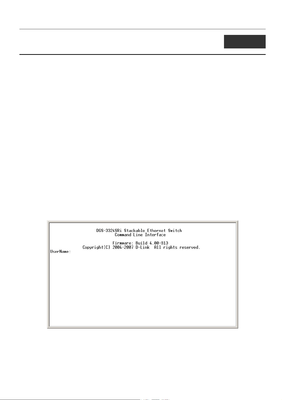
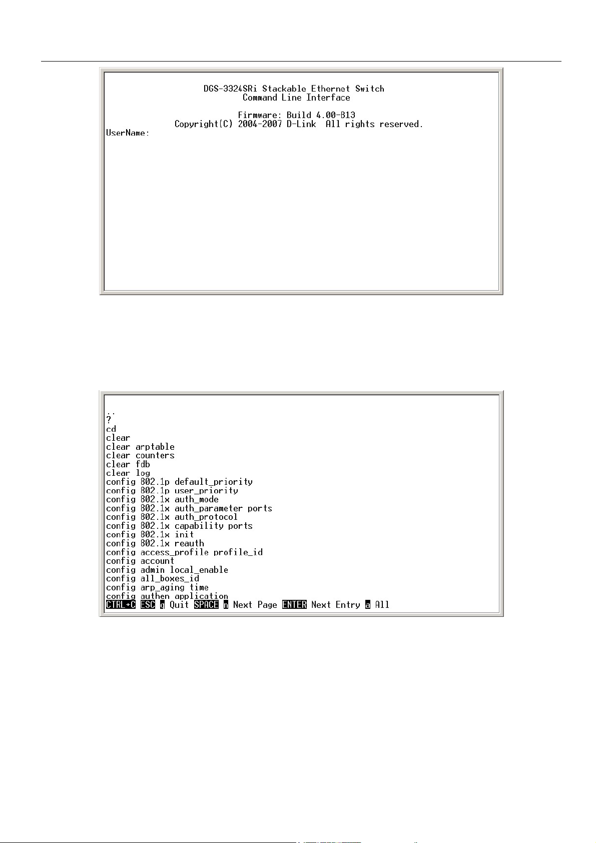
With the serial port properly connected to a management computer, the following screen should be visible. If this screen does
not appear, try pressing Ctrl+r to refresh the console screen.
Figure 1-1. Initial CLI screen
There is no initial username or password. Just press the Enter key twice to display the CLI input cursor − DGS-3324SRi:4#.
This is the command line where all commands are input.
1
Page 10
xStack Gigabit Layer 3 Switch Command Line Interface Manual
Setting the Switch’s IP Address
Each switch must be assigned its own IP Address, which is used for communication with an SNMP network manager or other
TCP/IP application (for example BOOTP, TFTP). The Switch’s default IP address is 10.90.90.90. You can change the default
switch IP address to meet the specification of your networking address scheme.
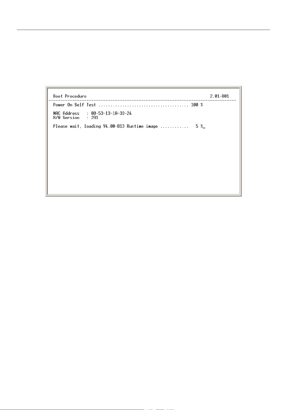
The Switch is also assigned a unique MAC address by the factory. This MAC address cannot be changed, and can be found on
the initial boot console screen – shown below.
Figure 1-2. Boot Screen
The Switch’s MAC address can also be found in the Web management program on the Switch Information (Basic Settings)
window on the Configuration menu.
The IP address for the Switch must be set before it can be managed with the Web-based manager. The Switch IP address can be
automatically set using BOOTP or DHCP protocols, in which case the actual address assigned to the Switch must be known.
The IP address may be set using the Command Line Interface (CLI) over the console serial port as follows:
1. Starting at the command line prompt, enter the commands config ipif System ipaddress
xxx.xxx.xxx.xxx/yyy.yyy.yyy.yyy. Where the x’s represent the IP address to be assigned to the IP interface named
System and the y’s represent the corresponding subnet mask.
2. Alternatively, you can enter config ipif System ipaddress xxx.xxx.xxx.xxx/z. Where the x’s represent the IP address
to be assigned to the IP interface named System and the z represents the corresponding number of subnets in CIDR
notation.
The IP interface named System on the Switch can be assigned an IP address and subnet mask which can then be used to connect
a management station to the Switch’s Telnet or Web-based management agent.
2
Page 11
xStack Gigabit Layer 3 Switch Command Line Interface Manual
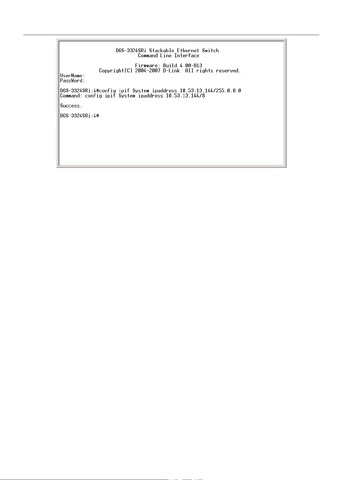
Figure 1-3. Assigning an IP Address
In the above example, the Switch was assigned an IP address of 10.53.13.144 with a subnet mask of 255.0.0.0. The system
message Success indicates that the command was executed successfully. The Switch can now be configured and managed via
Telnet and the CLI or via the Web-based management agent using the above IP address to connect to the Switch.
3
Page 12

xStack Gigabit Layer 3 Switch Command Line Interface Manual
2
USING THE CONSOLE CLI
The xStack family of switches supports a console management interface that allows the user to connect to the Switch’s
management agent via a serial port and a terminal or a computer running a terminal emulation program. The console can also be
used over the network using the TCP/IP Telnet protocol. The console program can be used to configure the Switch to use an
SNMP-based network management software over the network.
This chapter describes how to use the console interface to access the Switch, change its settings, and monitor its operation.
Note: Switch configuration settings are saved to non-volatile RAM using
the save command. The current configuration will then be retained in the
Switch’s NV-RAM, and reloaded when the Switch is rebooted. If the
Switch is rebooted without using the save command, the last configuration
saved to NV-RAM will be loaded.
Connecting to the Switch
The console interface is used by connecting the Switch to a VT100-compatible terminal or a computer running an ordinary
terminal emulator program (e.g., the HyperTerminal program included with the Windows operating system) using an RS-232C
serial cable. Your terminal parameters will need to be set to:
• VT-100 compatible
• 115200 baud
• 8 data bits
• No parity
• One stop bit
• No flow control
You can also access the same functions over a Telnet interface. Once you have set an IP address for your Switch, you can use a
Telnet program (in VT-100 compatible terminal mode) to access and control the Switch. All of the screens are identical,
whether accessed from the console port or from a Telnet interface.
After the Switch reboots and you have logged in, the console looks like this:
4
Page 13
xStack Gigabit Layer 3 Switch Command Line Interface Manual
Figure 2-1. Initial Console Screen
Commands are entered at the command prompts, DGS-3324SRi:4#, DGS-3324SR:4#, DXS-3326GSR:4#, DXS-3350SR:4#.
There are a number of helpful features included in the CLI. Entering the ? command will display a list of all of the top-level
commands.
Figure 2-2. The ? Command
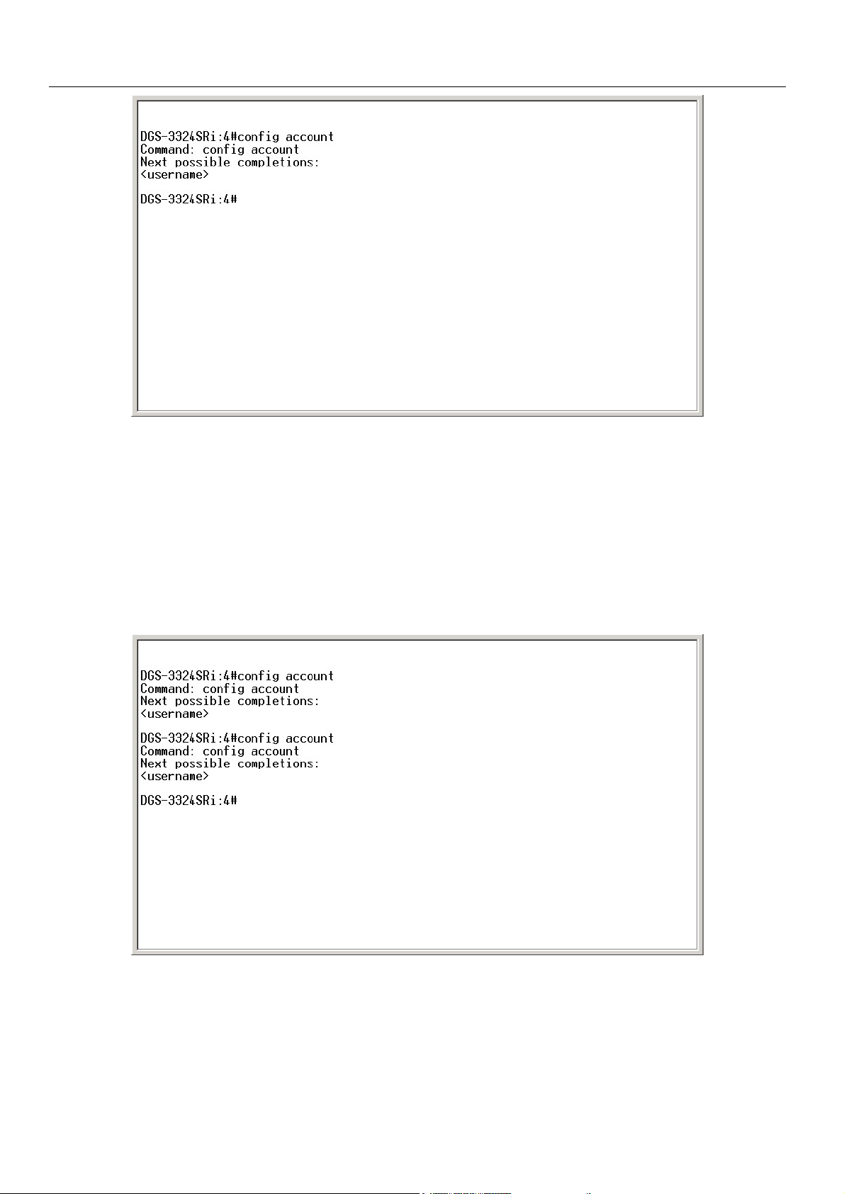
When you enter a command without its required parameters, the CLI will prompt you with a Next possible completions:
message.
5
Page 14
xStack Gigabit Layer 3 Switch Command Line Interface Manual
Figure 2-3. Example Command Parameter Help
In this case, the command config account was entered with the parameter <username>. The CLI will then prompt you to enter
the <username> with the message, Next possible completions:. Every command in the CLI has this feature, and complex
commands have several layers of parameter prompting.
In addition, after typing any given command plus one space, you can see all of the next possible sub-commands, in sequential
order, by repeatedly pressing the Tab key.
To re-enter the previous command at the command prompt, press the up arrow cursor key. The previous command will appear at
the command prompt.
Figure 2-4. Using the Up Arrow to Re-enter a Command
In the above example, the command config account was entered without the required parameter <username>, the CLI returned
the Next possible completions: <username> prompt. The up arrow cursor control key was pressed to re-enter the previous
command (config account) at the command prompt. Now the appropriate User name can be entered and the config account
command re-executed.
6
Page 15
xStack Gigabit Layer 3 Switch Command Line Interface Manual
All commands in the CLI function in this way. In addition, the syntax of the help prompts are the same as presented in this
manual − angle brackets < > indicate a numerical value or character string, braces { } indicate optional parameters or a choice of
parameters, and brackets [ ] indicate required parameters.
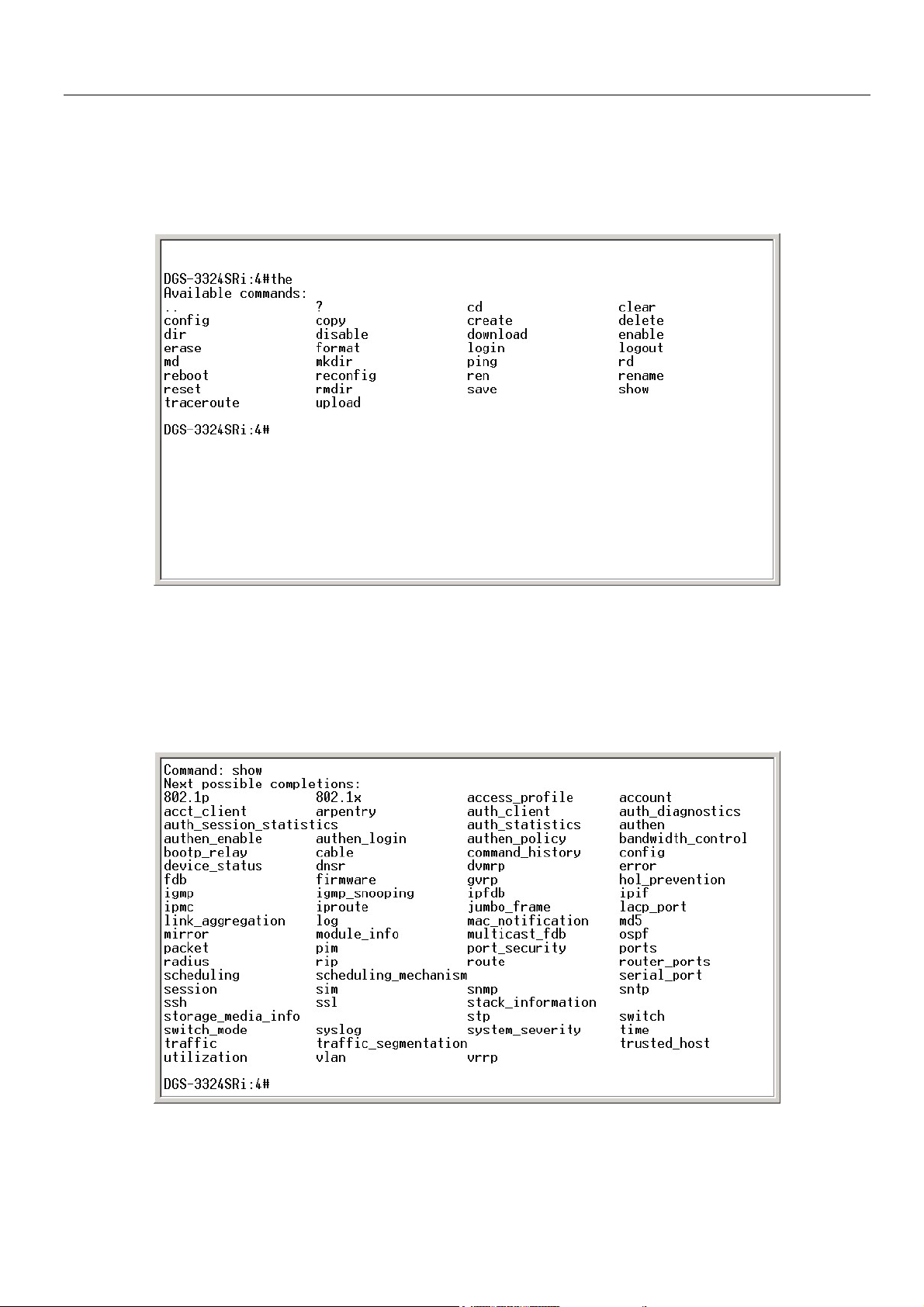
If a command is entered that is unrecognized by the CLI, the top-level commands will be displayed under the Available
commands: prompt.
Figure 2-5. The Available Commands Prompt
The top-level commands consist of commands such as show or config. Most of these commands require one or more parameters
to narrow the top-level command. This is equivalent to show what? or config what? Where the what? is the next parameter.
For example, if you enter the show command with no additional parameters, the CLI will then display all of the possible next
parameters.
Figure 2-6. Next possible completions: Show Command
7
Page 16

xStack Gigabit Layer 3 Switch Command Line Interface Manual
In the above example, all of the possible next parameters for the show command are displayed. At the next command prompt,
the up arrow was used to re-enter the show command, followed by the account parameter. The CLI then displays the user
accounts configured on the Switch.
8
Page 17
xStack Gigabit Layer 3 Switch Command Line Interface Manual
3
COMMAND SYNTAX
The following symbols are used to describe how command entries are made and values and arguments are specified in this
manual. The online help contained in the CLI and available through the console interface uses the same syntax.
Note: All commands are case-sensitive. Be sure to disable Caps Lock or
any other unwanted function that changes text case.
<angle brackets>
Purpose Encloses a variable or value that must be specified.
Syntax
Description In the above syntax example, you must supply an IP interface
Example Command
create ipif <ipif_name> vlan <vlan_name 32> ipaddress
<network_address>
name in the <ipif_name> space, a VLAN name in the
<vlan_name 32> space, and the network address in the
<network_address> space. Do not type the angle brackets.
create ipif Engineering vlan Design ipaddress
10.24.22.5/255.0.0.0
[square brackets]
Purpose Encloses a required value or set of required arguments. One
value or argument can be specified.
Syntax
Description
Example Command
In the above syntax example, you must specify either an admin
or a user level account to be created. Do not type the square
create account [admin | user]
brackets.
create account admin
| vertical bar
Purpose Separates two or more mutually exclusive items in a list, one of
which must be entered.
Syntax
Description In the above syntax example, you must specify either
community, or detail. Do not type the backslash.
Example Command
show snmp [community | detail]
show snmp community
9
Page 18
xStack Gigabit Layer 3 Switch Command Line Interface Manual
{braces}
Purpose Encloses an optional value or set of optional arguments.
Syntax
Description In the above syntax example, you have the option to specify
config or system. It is not necessary to specify either optional
value, however the effect of the system reset is dependent on
which, if any, value is specified. Therefore, with this example
there are three possible outcomes of performing a system
reset. See the following chapter, Basic Commands for more
Example command
reset {[config | system]}
details about the reset command.
reset config
Line Editing Key Usage
Delete Deletes the character under the cursor and then shifts the
remaining characters in the line to the left.
Backspace Deletes the character to the left of the cursor and shifts the
remaining characters in the line to the left.
Left Arrow Moves the cursor to the left.
Right Arrow Moves the cursor to the right.
Up Arrow Repeat the previously entered command. Each time the up
arrow is pressed, the command previous to that displayed
appears. This way it is possible to review the command history
for the current session. Use the down arrow to progress
sequentially forward through the command history list.
Down Arrow The down arrow will display the next command in the command
history entered in the current session. This displays each
command sequentially as it was entered. Use the up arrow to
review previous commands.
Tab Shifts the cursor to the next field to the left.
Multiple Page Display Control Keys
Space Displays the next page.
CTRL+c Stops the display of remaining pages when multiple pages are to
be displayed.
ESC Stops the display of remaining pages when multiple pages are to
be displayed.
n Displays the next page.
p Displays the previous page.
q Stops the display of remaining pages when multiple pages are to
be displayed.
r Refreshes the pages currently displayed.
a Displays the remaining pages without pausing between pages.
Enter Displays the next line or table entry.
10
Page 19
xStack Gigabit Layer 3 Switch Command Line Interface Manual
4
BASIC SWITCH COMMANDS
The basic switch commands in the Command Line Interface (CLI) are listed (along with the appropriate parameters) in the
following table.
Command Parameters
create account [admin | user] <username 15>
config account <username 15>
show account
delete account <username 15>
show config [current_config | config_in_NVRAM]
show session
show switch
show switch_mode
show device status
show module_info
show serial_port
config serial_port {baud_rate [115200] auto_logout [never | 2_minutes | 5_minutes |
10_minutes | 15_minutes]}
enable clipaging
disable clipaging
enable telnet <tcp_port_number 1-65535>
disable telnet
enable web <tcp_port_number 1-65535>
disable web
save [log | all]
reboot
reset {[config | system]}
login
logout
Each command is listed, in detail, in the following sections.
create account
Purpose Used to create user accounts.
Syntax
Description
create [admin | user] <username 15>
The create account command is used to create user accounts
that consist of a username of 1 to 15 characters and a password
of 0 to 15 characters. Up to 8 user accounts can be created.
11
Page 20

create account
Parameters admin <username> - Entering this parameter will give the
Restrictions Only Administrator-level users can issue this command.
Example usage:
To create an administrator-level user account with the username “dlink”.
xStack Gigabit Layer 3 Switch Command Line Interface Manual
specified user administrative-level priviledges over configuring
functions of the Switch. This user may perform any function listed
in this manual. A username of up to 15 characters must be
created with this command to identify the admin user.
user <username> - Entering this parameter will give the specified
user user-level priviledges over configuring functions of the
Switch. User-level priviledges limit the execution of many
commands listed in this manual. A username of up to 15
characters must be created with this command to identify the user.
Usernames can be between 1 and 15 characters.
Passwords can be between 0 and 15 characters.
DGS-3324SRi:4#create account admin dlink
Command: create account admin dlink
Enter a case-sensitive new password:****
Enter the new password again for confirmation:****
Success.
DGS-3324SRi:4#
config account
Purpose Used to configure user accounts
Syntax
Description
Parameters <username>- Enter the username of the account to be configured.
Restrictions Only Administrator-level users can issue this command.
Example usage:
To configure the user password of “dlink” account:
config account <username>
The config account command configures a user account that
has been created using the create account command.
Usernames can be between 1 and 15 characters.
Passwords can be between 0 15 characters.
12
Page 21

xStack Gigabit Layer 3 Switch Command Line Interface Manual
DGS-3324SRi:4#config account dlink
Command: config account dlink
Enter a old password:****
Enter a case-sensitive new password:****
Enter the new password again for confirmation:****
Success.
DGS-3324SRi:4#
show account
Purpose Used to display user accounts.
Syntax
Description Displays all user accounts created on the Switch. Up to 8 user
Parameters None.
Restrictions None.
Example usage:
To display the accounts that have been created:
show account
accounts can exist on the Switch at one time.
DGS-3324SRi:4#show account
Command: show account
Current Accounts:
Username Access Level
--------------- -----------dlink Admin
DGS-3324SRi:4#
delete account
Purpose Used to delete an existing user account.
Syntax
Description
Parameters <username>- Enter the username of the account to be deleted.
Restrictions Only Administrator-level users can issue this command.
Example usage:
To delete the admin account “System”:
delete account <username>
The delete account command deletes a user account that has
been created using the create account command.
13
Page 22

Example usage:
To delete the user account “System2”:
xStack Gigabit Layer 3 Switch Command Line Interface Manual
DGS-3324SRi:4#delete account System
Command: delete account System
Are you sure to delete the last administrator account?(y/n)y
Success.
DGS-3324SRi:4#
DGS-3324SRi:4#delete account System2
Command: delete account System2
Success.
DGS-3324SRi:4#
show config
Purpose Used to display a list of configuration commands entered into the
Switch.
Syntax
Description This command displays a list of configuration commands entered
Parameters current_config – Entering this parameter will display configurations
Restrictions None.
Example usage:
To view configurations entered on the Switch that were saved to NVRAM:
show config [current_config | config_in_NVRAM]
into the Switch.
entered without being saved to NVRAM.
config_in_NVRAM - Entering this parameter will display
configurations entered and saved to NVRAM.
14
Page 23

xStack Gigabit Layer 3 Switch Command Line Interface Manual
Command: show config config_in_NVRAM
#------------------------------------------------------------------------------------------------------
# DGS-3324SRi Configuration
#
# Firmware: Build 4.00-B13
# Copyright(C) 2004-2007 D-Link Corporation. All rights reserved.
#------------------------------------------------------------------------------------------------------
# BASIC
config serial_port baud_rate 115200 auto_logout never
enable telnet 23
enable web 80
enable clipaging
# STORM
config traffic control 1:1-1:26 broadcast disable multicast disable dlf disable
threshold 128
config traffic control 2:1-2:24 broadcast disable multicast disable dlf disable
CTRL+C ESC q Quit SPACE n Next Page ENTER Next Entry a All
show session
Purpose Used to display a list of currently logged-in users.
Syntax
Description This command displays a list of all the users that are logged-in at
Parameters None.
Restrictions None.
show session
the time the command is issued.
Example usage:
To display the way that the users logged in:
15
Page 24

xStack Gigabit Layer 3 Switch Command Line Interface Manual
DGS-3324SRi:4#show session
Command: show session
ID Live Time From Level Name
-- --------- -------------- ----- --------------*8 03:36:27 Serial Port 4 Anonymous
Total Entries: 1
show switch
Purpose Used to display information about the Switch.
Syntax
Description This command displays information about the Switch.
Parameters None.
Restrictions None.
Example usage:
To display the Switch information:
show switch
DGS-3324SRi:4#show switch
Command: show switch
Device Type : DGS-3324SRi Stackable Ethernet Switch
Unit ID : 1
MAC Address : DA-10-21-00-00-01
IP Address : 10.41.44.22 (Manual)
VLAN Name : default
Subnet Mask : 255.0.0.0
Default Gateway : 0.0.0.0
Boot PROM Version : Build 2.01-B01
Firmware Version : Build 4.00-B13
Hardware Version : 2A1
Device S/N :
System Name : DGS-3324SRi_#3
System Location : 7th_flr_east_cabinet
System Contact : Julius_Erving_212-555-6666
Spanning Tree : Disabled
GVRP : Disabled
IGMP Snooping : Disabled
RIP : Disabled
DVMRP : Disabled
PIM-DM : Disabled
OSPF : Disabled
TELNET : Enabled (TCP 23)
WEB : Enabled (TCP 80)
RMON : Enabled
802.1x : Disabled
16
Page 25

xStack Gigabit Layer 3 Switch Command Line Interface Manual
SSL Status : Disabled
SSH Status : Disabled
802.1x : Disabled
Jumbo Frame : Off
Clipaging : Enabled
MAC Notification : Disabled
Port Mirror : Disabled
SNTP : Disabled
Bootp Relay : Disabled
DNSR Status : Disabled
VRRP : Disabled
HOL Prevention State : Enabled
Syslog Global State : Disabled
Single IP Management : Disabled
Dual Image : Supported
DGS-3324SRi:4#
show switch_mode
Purpose Used to display the current switch mode.
Syntax
Description This command displays the current mode of operation of the
Parameters None.
Restrictions None.
Example usage:
To view the current switch mode:
DGS-3324SRi:4#show switch_mode
Command: show switch_mode
Switch is in Layer 3 mode
show switch_mode
Switch.
DGS-3324SRi:4#
show device_status
Purpose Used to display the current status of the hardware of the Switch.
Syntax
Description This command displays the current status of the Switch’s physical
Parameters None.
Restrictions None.
show device_status
elements.
17
Page 26

Example usage:
To show the current hardware status of the Switch:
show module_info
Purpose To show information concerning the added uplink module.
xStack Gigabit Layer 3 Switch Command Line Interface Manual
DGS-3324SRi:4#show device_status
Command: show device_status
ID Internal Power External power Side Fan Back Fan
--- ---------------- ---------------- ---------- ---------2 Active Fail OK OK
CTRL+C ESC q Quit SPACE n Next Page ENTER Next Entry a All
Syntax
Description This command is used to view information about the DEM-420X
Parameters None.
Restrictions None.
show module_info
uplink module added to an xStack switch. Currently, only the DXS3326GSR and the DXS-3350SR members of the xStack family have
the capability to add the optional DEM-420X module. Although the
DGS-3324SR and the DGS-3324SRi do not support the optional
module, information about the module can be viewed on these
switches if they are stacked with one of the switches that support the
optional module.
The following explains what is presented in the window:
Box ID – The ID of the switch in the switch stack.
Module Name – The name of the optional module. Currently,
switches in the xStack family only support the DEM-420X optional
module.
Rev. – The hardware revision of the optional module.
Serial No. – The serial number associated with this particular
optional module.
Description – A brief description of the optional module including
port count and module type.
Example usage:
To view information concerning the DEM-420X optional module added to an xStack switch.
DXS-3326GSR:4#show module_info
Command: show module_info
Box Module Name Rev. Serial Description
ID No.
------ ------------------ ------- --------- ------------------------------------------1 DEM420X 2A1 123456789 2-Port 10GE XFP Uplink Module
2 - - - -
18
Page 27

xStack Gigabit Layer 3 Switch Command Line Interface Manual
3 - - - 4 - - - 5 - - - 6 - - - 7 - - - -
8 - - - 9 - - - 10 - - - 11 - - - 12 - - - -
DXS-3326GSR:4#
show serial_port
Purpose Used to display the current serial port settings.
Syntax
Description This command displays the current serial port settings.
Parameters None.
Restrictions None.
Example usage:
To display the serial port setting:
show serial_port
DGS-3324SRi:4#show serial_port
Command: show serial_port
Baud Rate : 115200
Data Bits : 8
Parity Bits : None
Stop Bits : 1
Auto-Logout : 10 mins
DGS-3324SRi:4#
config serial_port
Purpose Used to configure the serial port.
Syntax
Description This command is used to configure the serial port’s baud rate
Parameters
config serial_port {baud_rate [115200] | auto_logout [never |
2_minutes | 5_minutes | 10_minutes | 15_minutes]}
and auto logout settings.
baud_rate [115200] − The serial bit rate that will be used to
communicate with the management host. This parameter is fixed
at 115200.
auto_logout – The user may select a time period from the
following list which the Switch will automatically log out of the
serial port.
• never − No time limit on the length of time the console can
19
Page 28

config serial_port
Restrictions Only administrator-level users can issue this command.
Example usage:
To configure baud rate:
xStack Gigabit Layer 3 Switch Command Line Interface Manual
be open with no user input.
• 2_minutes − The console will log out the current user if
there is no user input for 2 minutes.
• 5_minutes − The console will log out the current user if
there is no user input for 5 minutes.
• 10_minutes − The console will log out the current user if
there is no user input for 10 minutes.
• 15_minutes − The console will log out the current user if
there is no user input for 15 minutes.
DGS-3324SRi:4#config serial_port baud_rate 115200
Command: config serial_port baud_rate 115200
enable clipaging
Purpose Used to pause the scrolling of the console screen when the show
Syntax
Description This command is used when issuing the show command which
Parameters None.
Restrictions Only administrator-level users can issue this command.
Example usage:
To enable pausing of the screen display when the command output reaches the end of the page:
Success.
DGS-3324SRi:4#
command displays more than one page.
enable clipaging
causes the console screen to rapidly scroll through several
pages. This command will cause the console to pause at the end
of each page. The default setting is enable.
DGS-3324SRi:4#enable clipaging
Command: enable clipaging
Success.
DGS-3324SRi:4#
20
Page 29

xStack Gigabit Layer 3 Switch Command Line Interface Manual
disable clipaging
Purpose Used to disable the pausing of the console screen scrolling at
the end of each page when the show command displays more
than one screen of information.
Example usage:
To disable pausing of the screen display when show command output reaches the end of the page:
enable telnet
Syntax
Description This command is used to disable the pausing of the console
Parameters None.
Restrictions Only administrator-level users can issue this command.
DGS-3324SRi:4#disable clipaging
Command: disable clipaging
Success.
DGS-3324SRi:4#
disable clipaging
screen at the end of each page when the show command
would display more than one screen of information.
Purpose Used to enable communication with and management of the
Syntax
Description This command is used to enable the Telnet protocol on the
Parameters
Restrictions Only administrator-level users can issue this command.
Example usage:
To enable Telnet and configure port number:
Switch using the Telnet protocol.
enable telnet <tcp_port_number 1-65535>
Switch. The user can specify the TCP or UDP port number the
Switch will use to listen for Telnet requests.
<tcp_port_number 1-65535>
ports are numbered between 1 and 65535. The “well-known”
TCP port for the Telnet protocol is 23.
DGS-3324SRi:4#enable telnet 23
Command: enable telnet 23
Success.
DGS-3324SRi:4#
−
The TCP port number. TCP
21
Page 30

xStack Gigabit Layer 3 Switch Command Line Interface Manual
disable telnet
Purpose Used to disable the Telnet protocol on the Switch.
Syntax
Description This command is used to disable the Telnet protocol on the
Parameters None.
Restrictions Only administrator-level users can issue this command.
Example usage:
To disable the Telnet protocol on the Switch:
enable web
Purpose Used to enable the HTTP-based management software on the
disable telnet
Switch.
DGS-3324SRi:4#disable telnet
Command: disable telnet
Success.
DGS-3324SRi:4#
Switch.
Syntax
Description This command is used to enable the Web-based management
Parameters
Restrictions Only administrator-level users can issue this command.
Example usage:
To enable HTTP and configure port number:
enable web <tcp_port_number 1-65535>
software on the Switch. The user can specify the TCP port
number the Switch will use to listen for Telnet requests.
<tcp_port_number 1-65535> − The TCP port number. TCP ports
are numbered between 1 and 65535. The “well-known” port for
the Web-based management software is 80.
DGS-3324SRi:4#enable web 80
Command: enable web 80
Note: SSL will be disabled if web is enabled.
Success.
DGS-3324SRi:4#
22
Page 31

xStack Gigabit Layer 3 Switch Command Line Interface Manual
disable web
Purpose Used to disable the HTTP-based management software on the
Switch.
Syntax
Description This command disables the Web-based management software
Parameters None.
Restrictions Only administrator-level users can issue this command.
Example usage:
To disable HTTP:
save
Purpose Used to save changes in the Switch’s configuration to non-volatile
disable web
on the Switch.
DGS-3324SRi:4#disable web
Command: disable web
Success.
DGS-3324SRi:4#
RAM.
Syntax
Description This command is used to enter the current switch configuration into
Parameters
Restrictions Only administrator-level users can issue this command.
Example usage:
To save the Switch’s current configuration to non-volatile RAM:
save [log | all]
non-volatile RAM. The saved switch configuration will be loaded into
the Switch’s memory each time the Switch is restarted.
Entering just the save command will save only the Switch configuration
to NV-Ram.
log – Entering the log parameter will save only the log file to NV-RAM.
all – Entering the all command will save both the log file and the Switch
configuration to NV-RAM.
DXS-3326GSR:4#save
Command: save
Do you want to change current box id from AUTO mode to STATIC
mode? (y/n) n
Saving all configurations to NV-RAM… Done.
DXS-3326GSR:4#
23
Page 32

xStack Gigabit Layer 3 Switch Command Line Interface Manual
NOTE: The DGS-3324SRi does not support a change in box mode from
Auto to Static.
reboot
Purpose Used to restart the Switch.
Syntax
Description This command is used to restart the Switch.
Parameters None.
Restrictions None.
Example usage:
To restart the Switch:
DGS-3324SRi:4#reboot
Command: reboot
Are you sure want to proceed with the system reboot? (y/n)
Please wait, the Switch is rebooting...
reset
Purpose Used to reset the Switch to the factory default settings.
Syntax
Description This command is used to restore the Switch’s configuration to the
reboot
reset {[config | system]}
default settings assigned from the factory.
Parameters
Restrictions Only administrator-level users can issue this command.
Example usage:
To restore all of the Switch’s parameters to their default values:
DGS-3324SRi:4#reset config
Command: reset config
config − If the keyword ‘config’ is specified, all of the factory
default settings are restored on the Switch including the IP
address, user accounts, and the Switch history log. The Switch
will not save or reboot.
system − If the keyword ‘system’ is specified all of the factory
default settings are restored on the Switch. The Switch will save
and reboot after the settings are changed to default. Rebooting
will clear all entries in the Forwarding Data Base.
If no parameter is specified, the Switch’s current IP address, user
accounts, and the Switch history log are not changed. All other
parameters are restored to the factory default settings. The Switch
will not save or reboot.
24
Page 33

xStack Gigabit Layer 3 Switch Command Line Interface Manual
Success.
DGS-3324SRi:4#
login
Purpose Used to log in a user to the Switch’s console.
Syntax
Description This command is used to initiate the login procedure. The user
Parameters None.
Restrictions None.
Example usage:
To initiate the login procedure:
logout
Purpose Used to log out a user from the Switch’s console.
Syntax
Description This command terminates the current user’s session on the
login
will be prompted for his Username and Password.
DGS-3324SRi:4#login
Command: login
UserName:
logout
Switch’s console.
Parameters None.
Restrictions None.
Example usage:
To terminate the current user’s console session:
DGS-3324SRi:4#logout
25
Page 34

xStack Gigabit Layer 3 Switch Command Line Interface Manual
5
SWITCH PORT COMMANDS
The switch port commands in the Command Line Interface (CLI) are listed (along with the appropriate parameters) in the
following table.
Command Parameters
config ports [<portlist> | all] {speed [auto | 10_half | 10_full | 100_half | 100_full
| 1000_full {[master | slave]} | flow_control [enable | disable] |
learning [enable | disable] state [enable | disable] | description
<desc 32> | clear]}
show ports {<portlist>} {description}
Each command is listed, in detail, in the following sections.
config ports
Purpose Used to configure the Switch’s Ethernet port settings.
Syntax
Description This command allows for the configuration of the Switch’s
Parameters
[<portlist> | all] {speed [auto | 10_half | 10_full | 100_half |
100_full | 1000_full {[master | slave]} | flow_control [enable |
disable] | learning [enable | disable] state [enable | disable] |
description <desc 32> | clear]}
Ethernet ports. Only the ports listed in the <portlist> will be
affected.
all − Configure all ports on the Switch.
<portlist> − Specifies a range of ports to be configured. The port
list is specified by listing the lowest switch number and the
beginning port number on that switch, separated by a colon. Then
the highest switch number, and the highest port number of the
range (also separated by a colon) are specified. The beginning
and end of the port list range are separated by a dash. For
example, 1:3 specifies switch number 1, port 3. 2:4 specifies
switch number 2, port 4. 1:3-2:4 specifies all of the ports between
switch 1, port 3 and switch 2, port 4 − in numerical order.
auto − Enables auto-negotiation for the specified range of ports.
[10 | 100 | 1000] − Configures the speed in Mbps for the specified
range of ports.
[half | full] − Configures the specified range of ports as either full-
or half-duplex.
[master | slave] – The master and slave parameters refer to
connections running a 1000BASE-T cable for connection between
the Switch port and other device capable of a gigabit connection.
The master setting will allow the port to advertise capabilities
related to duplex, speed and physical layer type. The master
setting will also determine the master and slave relationship
between the two connected physical layers. This relationship is
necessary for establishing the timing control between the two
physical layers. The timing control is set on a master physical
layer by a local source. The slave setting uses loop timing, where
the timing comes form a data stream received from the master. If
26
Page 35

config ports
Restrictions Only administrator-level users can issue this command.
Example usage:
To configure the speed of port 3 of unit 1 to be 10 Mbps, full duplex, learning and state enable:
xStack Gigabit Layer 3 Switch Command Line Interface Manual
one connection is set for 1000 master, the other side of the
connection must be set for 1000 slave. Any other configuration will
result in a link down status for both ports.
flow_control [enable | disable] – Enable or disable flow control for
the specified ports.
learning [enable | disable] − Enables or disables the MAC address
learning on the specified range of ports.
state [enable | disable] − Enables or disables the specified range
of ports.
description <desc 32> - Enter an alphanumeric string of no more
than 32 characters to describe a selected port interface.
clear – Enter this command to clear the port description of the
selected port(s).
DGS-3324SRi:4#config ports 1:1-1:3 speed 10_full learning enable state
enable
Command: config ports 1:1-1:3 speed 10_full learning enable state
enable
Success.
DGS-3324SRi:4#
show ports
Purpose Used to display the current configuration of a range of ports.
Syntax
Description This command is used to display the current configuration of a
Parameters
show ports <portlist> {description}
range of ports.
<portlist> − Specifies a range of ports to be displayed. The port
list is specified by listing the lowest switch number and the
beginning port number on that switch, separated by a colon. Then
the highest switch number, and the highest port number of the
range (also separated by a colon) are specified. The beginning
and end of the port list range are separated by a dash. For
example, 1:3 specifies switch number 1, port 3. 2:4 specifies
switch number 2, port 4. 1:3-2:4 specifies all of the ports between
switch 1, port 3 and switch 2, port 4 − in numerical order.
{description} – Adding this parameter to the command will allow
the user to view previously configured descriptions set on various
ports on the Switch.
Restrictions None.
27
Page 36

Example usage:
To display the configuration of all ports on a standalone switch:
xStack Gigabit Layer 3 Switch Command Line Interface Manual
DGS-3324SRi:4#show ports
Command:show ports
Port Port Settings Connection Address
State Speed/Duplex/FlowCtrl Speed/Duplex/FlowCtrl Learning
------ -------- --------------------- --------------------- -------1:1 Enabled Auto/Enabled Link Down Enabled
1:2 Enabled Auto/Enabled Link Down Enabled
1:3 Enabled Auto/Enabled Link Down Enabled
1:4 Enabled Auto/Enabled Link Down Enabled
1:5 Enabled Auto/Enabled Link Down Enabled
1:6 Enabled Auto/Enabled Link Down Enabled
1:7 Enabled Auto/Enabled Link Down Enabled
1:8 Enabled Auto/Enabled Link Down Enabled
1:9 Enabled Auto/Enabled Link Down Enabled
1:10 Enabled Auto/Enabled 100M/Full/802.3x Enabled
1:11 Enabled Auto/Enabled Link Down Enabled
1:12 Enabled Auto/Enabled Link Down Enabled
1:13 Enabled Auto/Disabled Link Down Enabled
1:14 Enabled Auto/Disabled Link Down Enabled
1:15 Enabled Auto/Disabled Link Down Enabled
1:16 Enabled Auto/Disabled Link Down Enabled
1:17 Enabled Auto/Disabled Link Down Enabled
1:18 Enabled Auto/Disabled Link Down Enabled
1:19 Enabled Auto/Disabled Link Down Enabled
1:20 Enabled Auto/Disabled Link Down Enabled
CTRL+C ESC q Quit SPACE n Next Page p Previous Page r Refresh
Example usage;
To display port descriptions:
DGS-3324SRi:4#show ports 1:1 description
Command: show ports 1:1 description
Port Port Settings Connection Address
State Speed/Duplex/FlowCtrl Speed/Duplex/FlowCtrl Learning
------ -------- --------------------- --------------------- --------
1:1 Enabled Auto/Enabled Link Down Enabled
Description: Accounting
28
Page 37

xStack Gigabit Layer 3 Switch Command Line Interface Manual
6
PORT SECURITY COMMANDS
The port security commands in the Command Line Interface (CLI) are listed (along with the appropriate parameters) in the
following table.
Command Parameters
config port_security ports [<portlist> | all ] {admin_state [enable | disable] |
max_learning_addr <max_lock_no 0-64> |
lock_address_mode [Permanent | DeleteOnTimeout |
DeleteOnReset]}
show port_security {ports <portlist>}
delete
port_security_entry_vlan_name
Each command is listed, in detail, in the following sections.
<vlan_name 32> port <port> mac_address <macaddr>
config port_security ports
Purpose Used to configure port security settings.
Syntax
Description This command allows for the configuration of the port security
Parameters
[<portlist> | all ] {admin_state [enable | disable] |
max_learning_addr <max_lock_no 0-64> |
lock_address_mode [Permanent | DeleteOnTimeout |
DeleteOnReset]}
feature. Only the ports listed in the <portlist> are effected.
<portlist> − Specifies a range of ports to be configured. The port
list is specified by listing the lowest switch number and the
beginning port number on that switch, separated by a colon. Then
the highest switch number, and the highest port number of the
range (also separated by a colon) are specified. The beginning
and end of the port list range are separated by a dash. For
example, 1:3 specifies switch number 1, port 3. 2:4 specifies
switch number 2, port 4. 1:3-2:4 specifies all of the ports between
switch 1, port 3 and switch 2, port 4 − in numerical order.
all − Configure port security for all ports on the Switch.
admin_state [enable | disable] – Enable or disable port security for
the listed ports.
max_learning_addr <max_lock_no 0-64> - Use this to limit the
number of MAC addresses dynamically listed in the FDB for the
ports.
lock_address_mode [Permanent | DeleteOnTimeout |
DeleteOnReset] – Indicates the method of locking addresses. The
user has three choices:
Permanent – The locked addresses will not age out after
the aging timer expires.
DeleteOnTimeout – The locked addresses will age out
after the aging timer expires.
DeleteOnReset – The locked addresses will not age out
29
Page 38

config port_security ports
Restrictions Only administrator-level users can issue this command.
Example usage:
To configure the port security:
xStack Gigabit Layer 3 Switch Command Line Interface Manual
until the Switch has been reset.
DGS-3324SRi:4#config port_security ports 5:1-5:5 admin_state
enable max_learning_addr 5 lock_address_mode DeleteOnReset
Command: config port_security ports 5:1-5:5 admin_state
enable max_learning_addr 5 lock_address_mode DeleteOnReset
Success
show port_security
Purpose Used to display the current port security configuration.
Syntax
Description This command is used to display port security information of the
Parameters
Restrictions None.
Example usage:
DGS-3324SRi:4#
show port_security {ports <portlist>}
Switch ports. The information displayed includes port security admin
state, maximum number of learning address and lock mode.
ports <portlist> − Specifies a port or range of ports to be viewed.
The port list is specified by listing the lowest switch number and the
beginning port number on that switch, separated by a colon. Then the
highest switch number, and the highest port number of the range
(also separated by a colon) are specified. The beginning and end of
the port list range are separated by a dash. For example, 1:3
specifies switch number 1, port 3. 2:4 specifies switch number 2, port
4. 1:3-2:4 specifies all of the ports between switch 1, port 3 and
switch 2, port 4 − in numerical order.
To display the port security configuration:
DGS-3324SRi:4#show port_security ports 1:1-1:19
Command: show port_security ports 1:1-1:19
Port# Admin State Max. Learning Addr. Lock Address Mode
---- ----------- ------------------- ----------------1:1 Disabled 1 DeleteOnReset
1:2 Disabled 1 DeleteOnReset
1:3 Disabled 1 DeleteOnReset
1:4 Disabled 1 DeleteOnReset
1:5 Disabled 1 DeleteOnReset
1:6 Disabled 1 DeleteOnReset
30
Page 39

xStack Gigabit Layer 3 Switch Command Line Interface Manual
1:7 Enabled 10 DeleteOnReset
1:8 Disabled 1 DeleteOnReset
1:9 Disabled 1 DeleteOnReset
1:10 Disabled 1 DeleteOnReset
1:11 Disabled 1 DeleteOnReset
1:12 Disabled 1 DeleteOnReset
1:13 Disabled 1 DeleteOnReset
1:14 Disabled 1 DeleteOnReset
1:15 Disabled 1 DeleteOnReset
1:16 Disabled 1 DeleteOnReset
1:17 Disabled 1 DeleteOnReset
1:18 Disabled 1 DeleteOnReset
1:19 Disabled 1 DeleteOnReset
DGS-3324SRi:4#
delete port_security_entry_vlan_name
Purpose Used to delete an entry from the Switch’s port security settings.
Syntax
Description This command is used to remove an entry from the port security
Parameters <vlan_name 32> - Enter the corresponding VLAN of the entry the
Restrictions Only administrator-level users can issue this command.
Example usage:
To delete an entry from the port security list:
DGS-3324SRi:4#delete port_security_entry_vlan_name default
port 1:1 mac_address 00-0C-6E-73-2B-C9
Command: delete port_security_entry_vlan_name default port
1:1 mac_address 00-0C-6E-73-2B-C9
port_security_entry_vlan_name <vlan_name 32> port
delete
<port> mac_address <macaddr>
entries learned by the Switch and entered into the forwarding
database.
user wishes to delete.
port <port> - Enter the corresponding port of the entry to delete. The
port is specified by listing the lowest switch number and the
beginning port number on that switch, separated by a colon. For
example, 1:3 specifies switch number 1, port 3. 2:4 specifies switch
number 2, port 4.
mac_address <macaddr> - Enter the corresponding MAC address of
the entry to delete.
Success
DGS-3324SRi:4#
31
Page 40

xStack Gigabit Layer 3 Switch Command Line Interface Manual
p
7
NETWORK MANAGEMENT (SNMP) COMMANDS
The network management commands in the Command Line Interface (CLI) are listed (along with the appropriate parameters) in
the following table.
The xStack family of switches support the Simple Network Management Protocol (SNMP) versions 1, 2c, and 3. You can
specify which version of the SNMP you want to use to monitor and control the Switch. The three versions of SNMP vary in the
level of security provided between the management station and the network device. The following table lists the security
features of the three SNMP versions:
SNMP Version Authentication Method Description
v1 Community String
v2c Community String
v3 Username
v3 MD5 or SHA
v3 MD5 DES or SHA DES
Each command is listed, in detail, in the following sections.
Command Parameters
create snmp user create snmp user <SNMP_name 32> <groupname 32>
{encrypted [by_password auth [md5 <auth_password 8-16> | sha
<auth_password 8-20>] priv [none | des <priv_password 8-16>] |
by_key auth [md5 <auth_key 32-32> | sha <auth_key 40-40>]
priv [none | des <priv_key 32-32>]]}
delete snmp user <SNMP_name 32>
Community String is used for authentication − NoAuthNoPriv
Community String is used for authentication − NoAuthNoPriv
Username is used for authentication − NoAuthNoPriv
Authentication is based on the HMAC-MD5 or HMAC-SHA
algorithms − AuthNoPriv
Authentication is based on the HMAC-MD5 or HMAC-SHA
algorithms − AuthPriv.
DES 56-bit encryption is added based on the CBC-DES
(DES-56) standard
show snmp user
create snmp view <view_name 32> <oid> view_type [included | excluded]
delete snmp view <view_name 32> [all | oid]
show snmp view <view_name 32>
create snmp community <community_string 32> view <view_name 32> [read_only |
read_write]
delete snmp community <community_string 32>
show snmp community <community_string 32>
config snmp engineID <snmp_engineID>
show snmp engineID
create snmp group <groupname 32> {v1 | v2c |v3 [noauth_nopriv | auth_nopriv |
auth
riv ]} {read view <view name 32> | write view
32
Page 41

xStack Gigabit Layer 3 Switch Command Line Interface Manual
Command Parameters
<view_name 32> | notify_view <view_name 32>}
delete snmp group <groupname 32>
show snmp groups
create snmp host <ipaddr> {v1 |v2c | v3 [noauth_nopriv | auth_nopriv | auth_priv]}
<auth_string 32>
delete snmp host <ipaddr>
show snmp host <ipaddr>
create trusted_host <ipaddr>
delete trusted_host <ipaddr>
show trusted_host <ipaddr>
enable snmp traps
enable snmp
authenticate_traps
show snmp traps
disable snmp traps
disable snmp
authenticate_traps
config snmp system
contact
config snmp system
location
config snmp system
name
enable rmon
disable rmon
Each command is listed, in detail, in the following sections.
<sw_contact>
<sw_location>
<sw_name>
create snmp user
Purpose Used to create a new SNMP user and adds the user to an SNMP
group that is also created by this command.
Syntax
Description
create snmp user <SNMP_name 32> <groupname 32>
{encrypted [by_password auth [md5 <auth_password 8-16> |
sha <auth_password 8-20>] priv [none | des <priv_password 816>] | by_key auth [md5 <auth_key 32-32> | sha <auth_key 4040>] priv [none | des <priv_key 32-32>]]}
The create snmp user command creates a new SNMP user and
adds the user to an SNMP group that is also created by this
command. SNMP ensures:
Message integrity − Ensures that packets have not been tampered
with during transit.
Authentication − Determines if an SNMP message is from a valid
source.
33
Page 42

xStack Gigabit Layer 3 Switch Command Line Interface Manual
create snmp user
Encryption − Scrambles the contents of messages to prevent it from
being viewed by an unauthorized source.
Parameters
<username 32> − An alphanumeric name of up to 32 characters
that will identify the new SNMP user.
<groupname 32> − An alphanumeric name of up to 32 characters
that will identify the SNMP group the new SNMP user will be
associated with.
encrypted – Allows the user to choose a type of authorization for
authentication using SNMP. The user may choose:
•
by_password – Requires the SNMP user to enter a
password for authentication and privacy. The password is
defined by specifying the auth_password below. This
method is recommended.
•
by_key – Requires the SNMP user to enter a encryption
key for authentication and privacy. The key is defined by
specifying the key in hex form below. This method is not
recommended.
auth - The user may also choose the type of authentication
algorithms used to authenticate the snmp user. The choices are:
•
md5 − Specifies that the HMAC-MD5-96 authentication
level will be used. md5 may be utilized by entering one of
the following:
<auth password 8-16> - An alphanumeric sting of
between 8 and 16 characters that will be used to
authorize the agent to receive packets for the host.
<auth_key 32-32> - Enter an alphanumeric sting of
exactly 32 characters, in hex form, to define the key that
will be used to authorize the agent to receive packets for
the host.
−
•
priv – Adding the priv (privacy) parameter will allow for encryption in
addition to the authentication algorithm for higher security. The user
may choose:
•
Specifies that the HMAC-SHA-96 authentication
sha
level will be used.
<auth password 8-20> - An alphanumeric sting of
between 8 and 20 characters that will be used to
authorize the agent to receive packets for the host.
<auth_key 40-40> - Enter an alphanumeric sting of
exactly 40 characters, in hex form, to define the key that
will be used to authorize the agent to receive packets for
the host.
des – Adding this parameter will allow for a 56-bit
encryption to be added using the DES-56 standard using:
<priv_password 8-16> - An alphanumeric string of
between 8 and 16 characters that will be used to
encrypt the contents of messages the host sends to
34
Page 43

Example usage:
To create an SNMP user on the Switch:
xStack Gigabit Layer 3 Switch Command Line Interface Manual
create snmp user
the agent.
• <priv_key 32-32> - Enter an alphanumeric key string
of exactly 32 characters, in hex form, that will be
used to encrypt the contents of messages the host
sends to the agent.
none – Adding this parameter will add no encryption.
Restrictions Only administrator-level users can issue this command.
DGS-3324SRi:4#create snmp user dlink default encrypted
by_password auth md5 auth_password priv none
Command: create snmp user dlink default encrypted
by_password auth md5 auth_password priv none
Success.
delete snmp user
Purpose Used to remove an SNMP user from an SNMP group and also to
Syntax
Description
Parameters
Restrictions Only administrator-level users can issue this command.
Example usage:
To delete a previously entered SNMP user on the Switch:
DGS-3324SRi:4#
delete the associated SNMP group.
delete snmp user <SNMP_name 32>
The delete snmp user command removes an SNMP user from
its SNMP group and then deletes the associated SNMP group.
<SNMP_name 32> − An alphanumeric string of up to 32
characters that identifies the SNMP user that will be deleted.
DGS-3324SRi:4#delete snmp user dlink
Command: delete snmp user dlink
Success.
DGS-3324SRi:4#
35
Page 44

xStack Gigabit Layer 3 Switch Command Line Interface Manual
show snmp user
Purpose Used to display information about each SNMP username in the
SNMP group username table.
Syntax
Description
Parameters None.
Restrictions Only administrator-level users can issue this command.
Example usage:
To display the SNMP users currently configured on the Switch:
show snmp user
The show snmp user command displays information about each
SNMP username in the SNMP group username table.
DGS-3324SRi:4#show snmp user
Command: show snmp user
Username Group Name VerAuthPriv
--------------- -------------------- -------------------- initial initial V3 None None
Total Entries: 1
DGS-3324SRi:4#
create snmp view
Purpose Used to assign views to community strings to limit which MIB
Syntax create snmp view <view_name 32> <oid> view_type [included |
Description The create snmp view command assigns views to community
Parameters <view_name 32> − An alphanumeric string of up to 32 characters
Restrictions Only administrator-level users can issue this command.
Example usage:
objects and SNMP manager can access.
excluded]
strings to limit which MIB objects an SNMP manager can access.
that identifies the SNMP view that will be created.
<oid> − The object ID that identifies an object tree (MIB tree) that
will be included or excluded from access by an SNMP manager.
included − Include this object in the list of objects that an SNMP
manager can access.
excluded − Exclude this object from the list of objects that an SNMP
manager can access.
To create an SNMP view:
36
Page 45

xStack Gigabit Layer 3 Switch Command Line Interface Manual
DGS-3324SRi:4#create snmp view dlinkview 1.3.6 view_type included
Command: create snmp view dlinkview 1.3.6 view_type included
Success.
DGS-3324SRi:4#
delete snmp view
Purpose Used to remove an SNMP view entry previously created on the
Switch.
Syntax
Description
Parameters
Restrictions Only administrator-level users can issue this command.
Example usage:
To delete a previously configured SNMP view from the Switch:
delete snmp view <view_name 32> [all | <oid>]
The delete snmp view command is used to remove an SNMP
view previously created on the Switch.
<view_name 32> − An alphanumeric string of up to 32 characters
that identifies the SNMP view to be deleted.
all − Specifies that all of the SNMP views on the Switch will be
deleted.
<oid> − The object ID that identifies an object tree (MIB tree) that
will be deleted from the Switch.
DGS-3324SRi:4#delete snmp view dlinkview all
Command: delete snmp view dlinkview all
Success.
show snmp view
Purpose Used to display an SNMP view previously created on the Switch.
Syntax
Description
Parameters
Restrictions None.
Example usage:
To display SNMP view configuration:
DGS-3324SRi:4#
show snmp view {<view_name 32>}
The show snmp view command displays an SNMP view
previously created on the Switch.
<view_name 32> − An alphanumeric string of up to 32 characters
that identifies the SNMP view that will be displayed.
37
Page 46

xStack Gigabit Layer 3 Switch Command Line Interface Manual
DGS-3324SRi:4#show snmp view
Command: show snmp view
Vacm View Table Settings
View Name Subtree View Type
-------------------- ------------------------- --------- ReadView 1 Included
WriteView 1 Included
NotifyView 1.3.6 Included
restricted 1.3.6.1.2.1.1 Included
restricted 1.3.6.1.2.1.11 Included
restricted 1.3.6.1.6.3.10.2.1 Included
restricted 1.3.6.1.6.3.11.2.1 Included
restricted 1.3.6.1.6.3.15.1.1 Included
CommunityView 1 Included
CommunityView 1.3.6.1.6.3 Excluded
CommunityView 1.3.6.1.6.3.1 Included
Total Entries: 11
DGS-3324SRi:4#
create snmp community
Purpose Used to create an SNMP community string to define the relationship
between the SNMP manager and an agent. The community string
acts like a password to permit access to the agent on the Switch.
One or more of the following characteristics can be associated with
the community string:
An Access List of IP addresses of SNMP managers that are
permitted to use the community string to gain access to the Switch’s
SNMP agent.
An MIB view that defines the subset of all MIB objects that will be
accessible to the SNMP community.
Read-write or read-only level permission for the MIB objects
accessible to the SNMP community.
Syntax
Description
Parameters
create snmp community <community_string 32> view
<view_name 32> [read_only | read_write]
The create snmp community command is used to create an SNMP
community string and to assign access-limiting characteristics to this
community string.
<community_string 32> − An alphanumeric string of up to 32
characters that is used to identify members of an SNMP community.
This string is used like a password to give remote SNMP managers
access to MIB objects in the Switch’s SNMP agent.
view <view_name 32> − An alphanumeric string of up to 32
characters that is used to identify the group of MIB objects that a
remote SNMP manager is allowed to access on the Switch.
read_only − Specifies that SNMP community members using the
community string created with this command can only read the
contents of the MIBs on the Switch.
read_write − Specifies that SNMP community members using the
community string created with this command can read from and
38
Page 47

create snmp community
Restrictions Only administrator-level users can issue this command.
Example usage:
To create the SNMP community string “dlink:”
delete snmp community
Purpose Used to remove a specific SNMP community string from the
xStack Gigabit Layer 3 Switch Command Line Interface Manual
write to the contents of the MIBs on the Switch.
DGS-3324SRi:4#create snmp community dlink view ReadView read_write
Command: create snmp community dlink view ReadView read_write
Success.
DGS-3324SRi:4#
Switch.
Syntax
Description
Parameters
Restrictions Only administrator-level users can issue this command.
Example usage:
To delete the SNMP community string “dlink:”
delete snmp community <community_string 32>
The delete snmp community command is used to remove a
previously defined SNMP community string from the Switch.
<community_string 32> − An alphanumeric string of up to 32
characters that is used to identify members of an SNMP
community. This string is used like a password to give remote
SNMP managers access to MIB objects in the Switch’s SNMP
agent.
DGS-3324SRi:4#delete snmp community dlink
Command: delete snmp community dlink
Success.
DGS-3324SRi:4#
show snmp community
Purpose Used to display SNMP community strings configured on the
Switch.
Syntax
Description
show snmp community {<community_string 32>}
The show snmp community command is used to display SNMP
community strings that are configured on the Switch.
39
Page 48

xStack Gigabit Layer 3 Switch Command Line Interface Manual
show snmp community
Parameters
Restrictions None.
Example usage:
To display the currently entered SNMP community strings:
<community_string 32> − An alphanumeric string of up to 32
characters that is used to identify members of an SNMP
community. This string is used like a password to give remote
SNMP managers access to MIB objects in the Switch’s SNMP
agent.
DGS-3324SRi:4#show snmp community
Command: show snmp community
SNMP Community Table
Community Name View Name Access Right
-------------------------------- -------------------------------- ----------- dlink ReadView read_write
private CommunityView read_write
public CommunityView read_only
Total Entries: 3
config snmp engineID
Purpose Used to configure a name for the SNMP engine on the Switch.
Syntax
Description
Parameters
Restrictions Only administrator-level users can issue this command.
Example usage:
To give the SNMP agent on the Switch the name “0035636666”
DGS-3324SRi:4#
config snmp engineID <snmp_engineID>
The config snmp engineID command configures a name for the
SNMP engine on the Switch.
<snmp_engineID> − An alphanumeric string that will be used to
identify the SNMP engine on the Switch.
DGS-3324SRi:4#config snmp engineID 0035636666
Command: config snmp engineID 0035636666
Success.
DGS-3324SRi:4#
40
Page 49

xStack Gigabit Layer 3 Switch Command Line Interface Manual
show snmp engineID
Purpose Used to display the identification of the SNMP engine on the
Switch.
Syntax
Description
Parameters None.
Restrictions None.
Example usage:
To display the current name of the SNMP engine on the Switch:
create snmp group
Purpose Used to create a new SNMP group, or a table that maps SNMP
show snmp engineID
The show snmp engineID command displays the identification of
the SNMP engine on the Switch.
DGS-3324SRi:4#show snmp engineID
Command: show snmp engineID
SNMP Engine ID : 0035636666
DGS-3324SRi:4#
users to SNMP views.
Syntax
Description
Parameters
create snmp group <groupname 32> [v1 | v2c | v3
[noauth_nopriv | auth_nopriv | auth_priv]] {read_view
<view_name 32> | write_view <view_name 32> | notify_view
<view_name 32>}
The create snmp group command creates a new SNMP group,
or a table that maps SNMP users to SNMP views.
<groupname 32> − An alphanumeric name of up to 32 characters
that will identify the SNMP group the new SNMP user will be
associated with.
v1 – Specifies that SNMP version 1 will be used. The Simple
Network Management Protocol (SNMP), version 1, is a network
management protocol that provides a means to monitor and
control network devices.
v2c – Specifies that SNMP version 2c will be used. The SNMP
v2c supports both centralized and distributed network
management strategies. It includes improvements in the Structure
of Management Information (SMI) and adds some security
features.
v3 – Specifies that the SNMP version 3 will be used. SNMP v3
provides secure access to devices through a combination of
authentication and encrypting packets over the network. SNMP v3
adds:
Message integrity − Ensures that packets have not been
tampered with during transit.
41
Page 50

xStack Gigabit Layer 3 Switch Command Line Interface Manual
create snmp group
noauth_nopriv − Specifies that there will be no authorization and
no encryption of packets sent between the Switch and a remote
SNMP manager.
auth_nopriv − Specifies that authorization will be required, but
there will be no encryption of packets sent between the Switch
and a remote SNMP manager.
auth_priv − Specifies that authorization will be required, and that
packets sent between the Switch and a remote SNMP manger will
be encrypted.
read_view – Specifies that the SNMP group being created can
request SNMP messages.
write_view – Specifies that the SNMP group being created has
write privileges.
Authentication − Determines if an SNMP message is from
a valid source.
Encryption − Scrambles the contents of messages to
prevent it being viewed by an unauthorized source.
Restrictions Only administrator-level users can issue this command.
Example usage:
To create an SNMP group named “sg1:”
<view_name 32> − An alphanumeric string of up to 32 characters
that is used to identify the group of MIB objects that a remote
SNMP manager is allowed to access on the Switch.
notify_view − Specifies that the SNMP group being created can
receive SNMP trap messages generated by the Switch’s SNMP
agent.
DGS-3324SRi:4#create snmp group sg1 v3 noauth_nopriv
read_view v1 write_view v1 notify_view v1
Command: create snmp group sg1 v3 noauth_nopriv read_view v1
write_view v1 notify_view v1
Success.
DGS-3324SRi:4#
delete snmp group
Purpose Used to remove an SNMP group from the Switch.
Syntax
Description
Parameters
delete snmp group <groupname 32>
The delete snmp group command is used to remove an SNMP
group from the Switch.
<groupname 32> − An alphanumeric name of up to 32 characters
that will identify the SNMP group to be deleted.
42
Page 51

delete snmp group
Restrictions Only administrator-level users can issue this command.
Example usage:
To delete the SNMP group named “sg1”.
show snmp groups
Purpose Used to display the group-names of SNMP groups currently
xStack Gigabit Layer 3 Switch Command Line Interface Manual
DGS-3324SRi:4#delete snmp group sg1
Command: delete snmp group sg1
Success.
DGS-3324SRi:4#
configured on the Switch. The security model, level, and status of
each group are also displayed.
Syntax
Description
Parameters None.
Restrictions None.
Example usage:
To display the currently configured SNMP groups on the Switch:
show snmp groups
The show snmp groups command displays the group-names of
SNMP groups currently configured on the Switch. The security
model, level, and status of each group are also displayed.
DGS-3324SRi:4#show snmp groups
Command: show snmp groups
Vacm Access Table Settings
Group Name : Group3
ReadView Name : ReadView
WriteView Name : WriteView
Notify View Name : NotifyView
Security Model : SNMPv3
Security Level : NoAuthNoPriv
Group Name : Group4
ReadView Name : ReadView
WriteView Name : WriteView
Notify View Name : NotifyView
Security Model : SNMPv3
Security Level : authNoPriv
Group Name : Group5
ReadView Name : ReadView
WriteView Name : WriteView
43
Page 52

xStack Gigabit Layer 3 Switch Command Line Interface Manual
Notify View Name : NotifyView
Security Model : SNMPv3
Security Level : authNoPriv
Group Name : Group6
ReadView Name : ReadView
WriteView Name : WriteView
Notify View Name : NotifyView
Security Model : SNMPv3
Security Level : authPriv
Group Name : Group7
ReadView Name : ReadView
WriteView Name : WriteView
Notify View Name : NotifyView
Security Model : SNMPv3
Security Level : authPriv
Group Name : initial
ReadView Name : restricted
WriteView Name :
Notify View Name : restricted
Security Model : SNMPv3
Security Level : NoAuthNoPriv
Group Name : ReadGroup
ReadView Name : CommunityView
WriteView Name :
Notify View Name : CommunityView
Security Model : SNMPv1
Security Level : NoAuthNoPriv
Group Name : ReadGroup
ReadView Name : CommunityView
WriteView Name :
Notify View Name : CommunityView
Security Model : SNMPv2
Security Level : NoAuthNoPriv
Group Name : WriteGroup
ReadView Name : CommunityView
WriteView Name : CommunityView
Notify View Name : CommunityView
Security Model : SNMPv1
Security Level : NoAuthNoPriv
Group Name : WriteGroup
ReadView Name : CommunityView
WriteView Name : CommunityView
Notify View Name : CommunityView
Security Model : SNMPv2
Security Level : NoAuthNoPriv
Total Entries: 10
DGS-3324SRi:4#
44
Page 53

xStack Gigabit Layer 3 Switch Command Line Interface Manual
create snmp host
Purpose Used to create a recipient of SNMP traps generated by the
Switch’s SNMP agent.
Syntax
Description
Parameters
create snmp host <ipaddr> [v1 | v2c | v3 [noauth_nopriv |
auth_nopriv | auth_priv]] <auth_string 32>
The create snmp host command creates a recipient of SNMP
traps generated by the Switch’s SNMP agent.
<ipaddr> − The IP address of the remote management station
that will serve as the SNMP host for the Switch.
v1 – Specifies that SNMP version 1 will be used. The Simple
Network Management Protocol (SNMP), version 1, is a network
management protocol that provides a means to monitor and
control network devices.
v2c – Specifies that SNMP version 2c will be used. The SNMP
v2c supports both centralized and distributed network
management strategies. It includes improvements in the Structure
of Management Information (SMI) and adds some security
features.
v3 – Specifies that the SNMP version 3 will be used. SNMP v3
provides secure access to devices through a combination of
authentication and encrypting packets over the network. SNMP
v3 adds:
Message integrity − Ensures that packets have not been
tampered with during transit.
Authentication − Determines if an SNMP message is from
a valid source.
Restrictions Only administrator-level users can issue this command.
Example usage:
To create an SNMP host to receive SNMP messages:
Encryption − Scrambles the contents of messages to
prevent it being viewed by an unauthorized source.
noauth_nopriv − Specifies that there will be no authorization and
no encryption of packets sent between the Switch and a remote
SNMP manager.
auth_nopriv − Specifies that authorization will be required, but
there will be no encryption of packets sent between the Switch
and a remote SNMP manager.
auth_priv − Specifies that authorization will be required, and that
packets sent between the Switch and a remote SNMP manger
will be encrypted.
<auth_sting 32> − An alphanumeric string used to authorize a
remote SNMP manager to access the Switch’s SNMP agent.
45
Page 54

xStack Gigabit Layer 3 Switch Command Line Interface Manual
DGS-3324SRi:4#create snmp host 10.48.74.100 v3 auth_priv public
Command: create snmp host 10.48.74.100 v3 auth_priv public
Success.
DGS-3324SRi:4#
delete snmp host
Purpose Used to remove a recipient of SNMP traps generated by the
Switch’s SNMP agent.
Syntax
Description
Parameters
Restrictions Only administrator-level users can issue this command.
Example usage:
To delete an SNMP host entry:
show snmp host
delete snmp host <ipaddr>
The delete snmp host command deletes a recipient of SNMP
traps generated by the Switch’s SNMP agent.
<ipaddr> − The IP address of a remote SNMP manager that will
receive SNMP traps generated by the Switch’s SNMP agent.
DGS-3324SRi:4#delete snmp host 10.48.74.100
Command: delete snmp host 10.48.74.100
Success.
DGS-3324SRi:4#
Purpose Used to display the recipient of SNMP traps generated by the
Syntax
Description
Parameters
Restrictions None.
Example usage:
To display the currently configured SNMP hosts on the Switch:
Switch’s SNMP agent.
show snmp host {<ipaddr>}
The show snmp host command is used to display the IP
addresses and configuration information of remote SNMP
managers that are designated as recipients of SNMP traps that
are generated by the Switch’s SNMP agent.
<ipaddr> − The IP address of a remote SNMP manager that will
receive SNMP traps generated by the Switch’s SNMP agent.
46
Page 55

xStack Gigabit Layer 3 Switch Command Line Interface Manual
DGS-3324SRi:4#show snmp host
Command: show snmp host
SNMP Host Table
Host IP Address SNMP Version Community Name/SNMPv3 User Name
--------------- --------------------- ------------------------------
10.48.76.23 V2c private
10.48.74.100 V3 authpriv public
Total Entries: 2
DGS-3324SRi:4#
create trusted_host
Purpose Used to create the trusted host.
Syntax
Description
Parameters
Restrictions Only administrator-level users can issue this command.
Example usage:
To create the trusted host:
create trusted_host <ipaddr>
The create trusted_host command creates the trusted host.
The Switch allows you to specify up to four IP addresses that are
allowed to manage the Switch via in-band SNMP or TELNET
based management software. These IP addresses must be
members of the Management VLAN. If no IP addresses are
specified, then there is nothing to prevent any IP address from
accessing the Switch, provided the user knows the Username
and Password.
<ipaddr> − The IP address of the trusted host.
DGS-3324SRi:4#create trusted_host 10.48.74.121
Command: create trusted_host 10.48.74.121
Success.
DGS-3324SRi:4#
show trusted_host
Purpose Used to display a list of trusted hosts entered on the Switch using
the create trusted_host command above.
Syntax
Description This command is used to display a list of trusted hosts entered on
show trusted_host
the Switch using the create trusted_host command above.
47
Page 56

show trusted_host
Parameters None.
Restrictions None.
Example Usage:
To display the list of trust hosts:
xStack Gigabit Layer 3 Switch Command Line Interface Manual
DGS-3324SRi:4#show trusted_host
Command: show trusted_host
Management Stations
IP Address
--------------------
10.53.13.94
Total Entries: 1
DGS-3324SRi:4#
delete trusted_host
Purpose
Syntax
Description This command is used to delete a trusted host entry made using
Parameters
Restrictions Only administrator-level users can issue this command.
Example Usage:
To delete a trusted host with an IP address 10.48.74.121:
Used to delete a trusted host entry made using the create
trusted_host command above.
delete trusted _host <ipaddr>
the create trusted_host command above.
<ipaddr> − The IP address of the trusted host.
DGS-3324SRi:4#delete trusted_host 10.48.74.121
Command: delete trusted_host 10.48.74.121
Success.
DGS-3324SRi:4#
enable snmp traps
Purpose Used to enable SNMP trap support.
Syntax
Description
enable snmp traps
The enable snmp traps command is used to enable SNMP trap
48
Page 57

xStack Gigabit Layer 3 Switch Command Line Interface Manual
enable snmp traps
support on the Switch.
Parameters None.
Restrictions Only administrator-level users can issue this command.
Example usage:
To enable SNMP trap support on the Switch:
DGS-3324SRi:4#enable snmp traps
Command: enable snmp traps
Success.
DGS-3324SRi:4#
enable snmp authenticate_traps
Purpose Used to enable SNMP authentication trap support.
Syntax
Description This command is used to enable SNMP authentication trap
Parameters None.
Restrictions Only administrator-level users can issue this command.
Example Usage:
To turn on SNMP authentication trap support:
show snmp traps
Purpose Used to show SNMP trap support on the Switch .
enable snmp authenticate_traps
support on the Switch.
DGS-3324SRi:4#enable snmp authenticate_traps
Command: enable snmp authenticate_traps
Success.
DGS-3324SRi:4#
Syntax
Description This command is used to view the SNMP trap support status
Parameters None.
Restrictions Only administrator-level users can issue this command.
Example usage:
To view the current SNMP trap support:
show snmp traps
currently configured on the Switch.
49
Page 58

xStack Gigabit Layer 3 Switch Command Line Interface Manual
DGS-3324SRi:4#show snmp traps
Command: show snmp traps
SNMP Traps : Enabled
Authenticate Traps : Enabled
DGS-3324SRi:4#
disable snmp traps
Purpose Used to disable SNMP trap support on the Switch.
Syntax
Description This command is used to disable SNMP trap support on the
Parameters None.
Restrictions Only administrator-level users can issue this command.
Example Usage:
To prevent SNMP traps from being sent from the Switch:
disable snmp authenticate_traps
Purpose Used to disable SNMP authentication trap support.
disable snmp traps
Switch.
DGS-3324SRi:4#disable snmp traps
Command: disable snmp traps
Success.
DGS-3324SRi:4#
Syntax
Description This command is used to disable SNMP authentication support on
Parameters None.
Restrictions Only administrator-level users can issue this command.
Example Usage:
To disable the SNMP authentication trap support:
disable snmp authenticate_traps
the Switch.
50
Page 59

xStack Gigabit Layer 3 Switch Command Line Interface Manual
DGS-3324SRi:4#disable snmp authenticate_traps
Command: disable snmp authenticate_traps
Success.
DGS-3324SRi:4#
config snmp system_contact
Purpose Used to enter the name of a contact person who is responsible for
the Switch.
Syntax
Description
Parameters <sw_contact> - A maximum of 255 characters is allowed. A NULL
Restrictions Only administrator-level users can issue this command.
Example usage:
To configure the Switch contact to “
DGS-3324SRi:4#config snmp system_contact MIS Department II
Command: config snmp system_contact MIS Department II
Success.
DGS-3324SRi:4#
config snmp system_contact {<sw_contact>}
The config snmp system_contact command is used to enter the
name and/or other information to identify a contact person who is
responsible for the Switch. A maximum of 255 character can be
used.
string is accepted if there is no contact.
MIS Department II
”:
config snmp system_location
Purpose Used to enter a description of the location of the Switch.
Syntax
Description
Parameters <sw_location> - A maximum of 255 characters is allowed. A NULL
Restrictions Only administrator-level users can issue this command.
config snmp system_location {<sw_location>}
The config snmp system_location command is used to enter a
description of the location of the Switch. A maximum of 255
characters can be used.
string is accepted if there is no location desired.
51
Page 60

Example usage:
xStack Gigabit Layer 3 Switch Command Line Interface Manual
To configure the Switch location for “
DGS-3324SRi:4#config snmp system_location HQ 5F
Command: config snmp system_location HQ 5F
Success.
DGS-3324SRi:4#
config snmp system_name
Purpose Used to configure the name for the Switch.
Syntax
Description
Parameters <sw_name> - A maximum of 255 characters is allowed. A NULL
Restrictions Only administrator-level users can issue this command.
config snmp system_name {<sw_name>}
The config snmp system_name command configures the name
of the Switch.
string is accepted if no name is desired.
HQ 5F
”:
Example usage:
To configure the Switch name for “
DGS-3324SRi:4#config snmp system_name DGS-3324SRi
Stackable Switch
Command: config snmp system_name DGS-3324SRi Stackable
Switch
Success.
DGS-3324SRi:4#
enable rmon
Purpose Used to enable RMON on the Switch.
Syntax
Description
enable rmon
This command is used, in conjunction with the disable rmon
command below, to enable and disable remote monitoring
(RMON) on the Switch.
DGS-3324SRi Stackable Switch
”:
Parameters None.
Restrictions Only administrator-level users can issue this command.
Example Usage:
To enable RMON:
52
Page 61

xStack Gigabit Layer 3 Switch Command Line Interface Manual
DGS-3324SRi:4#enable rmon
Command: enable rmon
Success.
DGS-3324SRi:4#
disable rmon
Purpose Used to disable RMON on the Switch.
Syntax
Description
Parameters None.
Restrictions Only administrator-level users can issue this command.
Example Usage:
To disable RMON:
DGS-3324SRi:4#disable rmon
Command: disable rmon
Success.
DGS-3324SRi:4#
disable rmon
This command is used, in conjunction with the enable rmon
command above, to enable and disable remote monitoring
(RMON) on the Switch.
53
Page 62

xStack Gigabit Layer 3 Switch Command Line Interface Manual
8
SWITCH UTILITY COMMANDS
The switch utility commands in the Command Line Interface (CLI) are listed (along with the appropriate parameters) in the
following table. Please note that commands concerning the CompactFlash card (cfg_fromCf, firmware_to CF, etc.) are specific
to the DGS-3324SRi only.
Command Parameters
download [firmware_fromTFTP <ipaddr> <path_filename 64> image_id <int
1-2> {unit [all | <unitid 1-12>]} | cfg_fromTFTP <ipaddr>
<path_filename 64> {increment} | firmware_fromCF <path_filename
64> image_id <int 1-2> | cfg_fromCF <path_filename 64>
{increment}]
upload [cfg_toTFTP <ipaddr> <path_filename 64> | log_toTFTP <ipaddr>
<path_filename 64> | [ firmware_toCF <path_filename 64>
image_id <int 1-2> | cfg_toCF <path_filename 64> | log_toCF
<path_filename 64>]
show
firmware_information
config firmware
image_id
ping <ipaddr> {times <value 1-255>} {timeout <sec 1-99>}
traceroute <ipaddr> {ttl <value 1-60> | port <value 30000-64900> | timeout
Each command is listed, in detail, in the following sections.
<int 1-2> [delete | boot_up]
<sec 1-65535> | probe <value <1-9>
download
Purpose Used to download and install new firmware or a switch
configuration file from a TFTP server or a CompactFlash memory
card.
Syntax
Description This command is used to download a new firmware or a switch
download [ firmware_fromTFTP <ipaddr> <path_filename 64>
image_id <int 1-2> {unit [all | <unitid 1-12>]} | cfg_fromTFTP
<ipaddr> <path_filename 64> {increment} | firmware_fromCF
<path_filename 64> image_id <int 1-2> | cfg_fromCF
<path_filename 64> {increment} ]
configuration file from a TFTP server or a CompactFlash memory
card.
Parameters
firmware_fromTFTP − Download and install new firmware on the
Switch from a TFTP server.
firmware_fromCF − Download and install new firmware on the
Switch from a CompactFlash server.
cfg_fromTFTP - Download a switch configuration file from a TFTP
server.
cfg_fromCF - Download a switch configuration file from a CF
server.
image_id <int 1-2>- This Switch holds two places for
54
Page 63

xStack Gigabit Layer 3 Switch Command Line Interface Manual
download
storing firmware so the user may store an extra firmware file
on the Switch. image_id 1 will hold the current boot up
firmware in use on the Switch, unless otherwise configured.
unit [all | <unitid>] − all specifies all units (switches),
<unitid> is the unit ID of the Switch that will receive the
download.
<ipaddr> − The IP address of the TFTP server. The TFTP
server must be on the same IP subnet as the Switch.
<path_filename 64> − The DOS path and filename of the
firmware or switch configuration file on the TFTP server or
CompactFlash card. For example, C:\3226S.had.
increment − Allows the download of a partial switch
configuration file. This allows a file to be downloaded that will
change only the Switch parameters explicitly stated in the
configuration file. All other switch parameters will remain
unchanged.
Restrictions The TFTP server must be on the same IP subnet as the Switch.
Only administrator-level users can issue this command.
Example usage:
To download a configuration file:
DGS-3324SRi:4#download cfg_to TFTP 10.48.74.121
c:\cfg\setting.txt
Command: download cfg_to TFTP 10.48.74.121 c:\cfg\setting.txt
Connecting to server................... Done.
Download configuration............. Done.
DGS-3324SRi:4#
upload
Purpose Used to upload the current switch settings or the switch history log
Syntax
to a TFTP server or a CompactFlash memory card.
upload [ cfg_toTFTP <ipaddr> <path_filename 64> |
log_toTFTP <ipaddr> <path_filename 64> | [ firmware_toCF
<path_filename 64> image_id <int 1-2> | cfg_toCF
<path_filename 64> | log_toCF <path_filename 64>]
Description This command is used to upload either the Switch’s current
settings, the Switch’s history log or firmware to a TFTP server or a
CompactFlash memory card.
Parameters
cfg_toTFTP − Specifies that the Switch’s current settings will be
uploaded to the TFTP server.
log_toTFTP − Specifies that the Switch’s current log will be
uploaded to the TFTP server.
firmware_toCF - Specifies that the Switch’s current firmware will
55
Page 64

upload
xStack Gigabit Layer 3 Switch Command Line Interface Manual
be uploaded to the CompactFlash card.
cfg_toCF - Specifies that the Switch’s current configuration
settings will be uploaded to the CompactFlash card.
log_toCF − Specifies that the Switch’s current log will be uploaded
to the CompactFlash card.
<ipaddr> − The IP address of the TFTP server. The TFTP
server must be on the same IP subnet as the Switch.
<path_filename 64> − Specifies the location of the Switch
configuration file on the TFTP server. This file will be
replaced by the uploaded file from the Switch.
image_id <int 1-2>- This Switch holds two places for
storing firmware so the user may store an extra firmware file
on the Switch. image_id 1 will hold the current firmware in
use on the Switch. The user may specify which firmware
version is to be uploaded to the CompactFlash card by
specifying the image_id of the firmware located on the
Switch. This parameter is only used for the firmware_toCF
parameter.
Restrictions The TFTP server must be on the same IP subnet as the Switch.
Example usage:
To upload a configuration file:
DGS-3324SRi:4#upload cfg_toTFTP 10.48.74.121 c:\cfg\log.txt
Command: upload cfg_to TFTP 10.48.74.121 c:\cfg\log.txt
Connecting to server................... Done.
Upload configuration...................Done.
DGS-3324SRi:4#
config firmware
Purpose To configure firmware currently in the Switch’s NV-RAM.
Syntax
Description This command allows the user to configure the dual image firmware
config firmware image_id <int 1-2> {delete | boot_up]
on the Switch. This Switch allows the user to hold two firmware
versions in its memory, labeled as image_id 1 and 2. Using this
command, the user may delete a firmware or set it as the boot up
firmware for the Switch. If the boot up firmware is not specified by
the user, image_id 1 will be the default boot up firmware.
Only administrator-level users can issue this command.
Parameters <int 1-2> - Select the ID number of the firmware in the Switch’s
memory to be configured.
delete – Selecting this parameter, along with the image_id will delete
this firmware from the Switch’s memory.
boot_up - Selecting this parameter, along with the image_id will set
this firmware as the default boot up runtime image firmware upon the
56
Page 65

xStack Gigabit Layer 3 Switch Command Line Interface Manual
config firmware
next reboot of the Switch.
Restrictions Only administrator-level users can issue this command.
Example usage:
To delete a firmware from the Switch’s memory:
DGS-3324SRi:4#config firmware image_id 2 delete
Command: config firmware image_id 2 delete
Success.
DGS-3324SRi:4#
Example usage:
To configure a firmware as the boot up runtime image firmware:
DGS-3324SRi:4#config firmware image_id 2 boot_up
Command: config firmware image_id 2 boot_up
Success.
DGS-3324SRi:4#
show firmware information
Purpose Used to display the firmware section information.
Syntax
Description This command is used to display the firmware section information.
Parameters None.
Restrictions None.
Example usage:
To display the current firmware information on the Switch:
show firmware information
57
Page 66

xStack Gigabit Layer 3 Switch Command Line Interface Manual
DGS-3324SRi:4#show firmware information
Command: show firmware information
Box ID Version Size(B) Update Time From User
--- -- -------- ------- ------------------- ------------------ --------------1 *1 4.00-B02 2360471 00000 days 00:00:00 Serial Port (PROM) Unknown
1 2 3.00-B13 1052372 00000 days 00:00:56 10.53.13.94 Anonymous
'*' means boot up section
(R) means firmware update thru SerialPort (RS232)
(T) means firmware update thru TELNET
(S) means firmware update thru SNMP
(W) means firmware update thru WEB
(SIM) means firmware update thru Single IP Management
DGS-3324SRi:4#
ping
Purpose Used to test the connectivity between network devices.
Syntax
Description The ping command sends Internet Control Message Protocol
Parameters <ipaddr> - Specifies the IP address of the host.
Restrictions None.
Example usage:
To ping the IP address 10.48.74.121 four times:
ping <ipaddr> {times <value 1-255>} {timeout <sec 1-99>}
(ICMP) echo messages to a remote IP address. The remote IP
address will then “echo” or return the message. This is used to
confirm connectivity between the Switch and the remote device.
times <value 1-255> - The number of individual ICMP echo
messages to be sent. The maximum value is 255. The default is 0.
timeout <sec 1-99> - Defines the time-out period while waiting for a
response from the remote device. A value of 1 to 99 seconds can
be specified. The default is 1 second.
Pinging an IP address without the times parameter will ping the
target device an infinite amount of times.
58
Page 67

xStack Gigabit Layer 3 Switch Command Line Interface Manual
DGS-3324SRi:4#ping 10.48.74.121 times 4
Command: ping 10.48.74.121
Reply from 10.48.74.121, time<10ms
Reply from 10.48.74.121, time<10ms
Reply from 10.48.74.121, time<10ms
Reply from 10.48.74.121, time<10ms
Ping statistics for 10.48.74.121
Packets: Sent =4, Received =4, Lost =0
DGS-3324SRi:4#
traceroute
Purpose Used to trace the routed path between the Switch and a destination
endstation.
Syntax
Description The traceroute command allows you to trace a route between the
Parameters <ipaddr> - Specifies the IP address of the host.
Restrictions None.
Example usage:
To trace the routed path between the Switch and 10.48.74.121.
traceroute <ipaddr> {ttl <value 1-60> | port <value 30000-64900>
| timeout <sec 1-65535> | probe <value <1-9>}
Switch and a give host on the network.
ttl <value 1-60> - The time to live value of the trace route request.
This is the maximum number of routers the traceroute command will
cross while seeking the network path between two devices.
port <value 30000-64900> - The port number. Must be above
1024.The value range is from 30000 to 64900.
timeout <sec 1-65535> - Defines the time-out period while waiting
for a response from the remote device. The user may choose an
entry between 1 and 65535 seconds.
probe <value 1-9> - The probe value is the number of times the
Switch will send probe packets to the next hop on the intended
traceroute path. The default is 1.
DGS-3324SRi:4#traceroute 10.48.74.121
Command: traceroute 10.48.74.121
1 <10ms 10.254.254.251
2 <10ms 10.55.25.35
3 <10ms 10.22.35.1
DGS-3324SRi:4#
probe 3
probe 3
59
Page 68

xStack Gigabit Layer 3 Switch Command Line Interface Manual
9
NETWORK MONITORING COMMANDS
The network monitoring commands in the Command Line Interface (CLI) are listed (along with the appropriate parameters) in
the following table.
Command Parameters
show packet ports <portlist>
show error ports <portlist>
show utilization [ports | cpu]
clear counters ports <portlist>
clear log
show log index <value_list>
enable syslog
disable syslog
show syslog
create syslog host [<index 1-4> | all ] {severity [informational | warning | all] | facility
[local0 | local1 | local2 | local3 | local4 | local5 | local6 | local7] |
udp_port <udp_port_number> | ipaddress <ipaddr> | state [enable
| disable]}
config syslog host <index 1-4> {severity [informational | warning | all] | facility [local0 |
local1 | local2 | local3 | local4 | local5 | local6 | local7] | udp_port
<udp_port_number> | ipaddress <ipaddr> | state [enable |
disable]}
config syslog host all {severity [informational | warning | all] | facility [local0 | local1 |
local2 | local3 | local4 | local5 | local6 | local7] | udp_port
<udp_port_number> | state [enable | disable]}
delete syslog host [<index 1-4> | all]
show syslog host [<index 1-4>]
config
system_severity
show system_severity
Each command is listed, in detail, in the following sections.
[trap | log | all] [critical | warning | information]
show packet ports
Purpose Used to display statistics about the packets sent and received by
the Switch.
Syntax
Description This command is used to display statistics about packets sent and
show packet ports <portlist>
received by ports specified in the port list. The results are
separated into three tables, labeled A, B, and C in the window
above. Table A is relevant to the size of the packets, Table B is
relevant to the type of packets and Table C is relevant to the type
60
Page 69

xStack Gigabit Layer 3 Switch Command Line Interface Manual
show packet ports
of frame associated with these packets.
Parameters
Restrictions None.
Example usage:
To display the packets analysis for port 7 of module 2:
<portlist> − Specifies a range of ports to be displayed. The port list
is specified by listing the lowest switch number and the beginning
port number on that switch, separated by a colon. Then the
highest switch number, and the highest port number of the range
(also separated by a colon) are specified. The beginning and end
of the port list range are separated by a dash. For example, 1:3
specifies switch number 1, port 3. 2:4 specifies switch number 2,
port 4. 1:3-2:4 specifies all of the ports between switch 1, port 3
and switch 2, port 4 − in numerical order.
DGS-3324SRi:4#show packet port 2:7
Port number : 2:7 (A) (B)
Frame Size Frame Counts Frames/sec Frame Type Total Total/sec
------------ ------------ ---------- ---------- ------- ---------
64 3275 10 RX Bytes 408973 1657
65-127 755 10 RX Frames 4395 19
128-255 316 1
256-511 145 0 TX Bytes 7918 178
512-1023 15 0 TX Frames 111 2
1024-1518 0 0
(C)
Unicast RX 152 1
Multicast RX 557 2
Broadcast RX 3686 16
CTRL+C ESC q Quit SPACE n Next Page p Previous Page r Refresh
show error ports
Purpose Used to display the error statistics for a range of ports.
Syntax
Description This command will display all of the packet error statistics
Parameters
show error ports <portlist>
collected and logged by the Switch for a given port list.
<portlist> − Specifies a range of ports to be displayed. The port
list is specified by listing the lowest switch number and the
beginning port number on that switch, separated by a colon.
Then the highest switch number, and the highest port number of
the range (also separated by a colon) are specified. The
beginning and end of the port list range are separated by a dash.
For example, 1:3 specifies switch number 1, port 3. 2:4 specifies
switch number 2, port 4. 1:3-2:4 specifies all of the ports
between switch 1, port 3 and switch 2, port 4 − in numerical
order.
61
Page 70

show error ports
Restrictions None.
Example usage:
To display the errors of the port 3 of module 1:
xStack Gigabit Layer 3 Switch Command Line Interface Manual
DGS-3324SRi:4#show errors ports 1:3
Command:show errors ports 1:3
RX Frames TX Frames
--------------- ---------------CRC Error 19 Excessive Deferral 0
Undersize 0 CRC Error 0
Oversize 0 Late Collision 0
Fragment 0 Excessive Collision 0
Jabber 11 Single Collision 0
Drop Pkts 20837 Collision 0
CTRL+C ESC q Quit SPACE n Next Page p Previous Page r Refresh
show utilization
Purpose Used to display real-time port and cpu utilization statistics.
Syntax
Description This command will display the real-time port and cpu utilization
Parameters cpu – Entering this parameter will display the current cpu
Restrictions None.
Example usage:
To display the port utilization statistics:
show utilization [ports | cpu]
statistics for the Switch.
utilization of the Switch, as a percentage.
ports - Entering this parameter will display the current utilization
of all ports on the Switch.
62
Page 71

xStack Gigabit Layer 3 Switch Command Line Interface Manual
DGS-3324SRi:4#show utilization ports
Command: show utilization ports
Port TX/sec RX/sec Util Port TX/sec RX/sec Util
---- ---------- ---------- ---- ---- ---------- ---------- --- 1:1 0 0 0 1:22 0 0 0
1:2 0 0 0 1:23 0 0 0
1:3 0 0 0 1:24 0 0 0
1:4 0 0 0 2:1 0 0 0
1:5 0 0 0 2:2 0 0 0
1:6 0 0 0 2:3 0 0 0
1:7 0 0 0 2:4 0 0 0
1:8 0 0 0 2:5 0 0 0
1:9 0 0 0 2:6 0 0 0
1:10 0 0 0 2:7 0 30 1
1:11 0 0 0 2:8 0 0 0
1:12 0 0 0 2:9 30 0 1
1:13 0 0 0 2:10 0 0 0
1:14 0 0 0 2:11 0 0 0
1:15 0 0 0 2:12 0 0 0
1:16 0 0 0 2:13 0 0 0
1:17 0 0 0 2:14 0 0 0
1:18 0 0 0 2:15 0 0 0
1:19 0 0 0 2:16 0 0 0
1:20 0 0 0 2:17 0 0 0
1:21 0 0 0 2:18 0 0 0
CTRL+C ESC q Quit SPACE n Next Page p Previous Page r Refresh
To display the current cpu utilization:
DGS-3324SRi:4#show utilization cpu
Command: show utilization cpu
CPU utilization :
------------------------------------------------------------------------------Five seconds - 15% One minute - 25% Five minutes - 14%
DGS-3324SRi:4#
clear counters
Purpose Used to clear the Switch’s statistics counters.
Syntax
Description This command will clear the counters used by the Switch to compile
Parameters
clear counters {ports <portlist>}
statistics.
<portlist> − Specifies a range of ports to be configured. The port list
is specified by listing the lowest switch number and the beginning
port number on that switch, separated by a colon. Then the highest
switch number, and the highest port number of the range (also
separated by a colon) are specified. The beginning and end of the
port list range are separated by a dash. For example, 1:3 specifies
switch number 1, port 3. 2:4 specifies switch number 2, port 4. 1:32:4 specifies all of the ports between switch 1, port 3 and switch 2,
port 4 − in numerical order.
63
Page 72

xStack Gigabit Layer 3 Switch Command Line Interface Manual
clear counters
Restrictions Only administrator-level users can issue this command.
Example usage:
To clear the counters:
DGS-3324SRi:4#clear counters ports 2:7-2:9
Command: clear counters ports 2:7-2:9
Success.
DGS-3324SRi:4#
clear log
Purpose Used to clear the Switch’s history log.
Syntax
Description This command will clear the Switch’s history log.
Parameters None.
Restrictions Only administrator-level users can issue this command.
Example usage:
To clear the log information:
show log
Purpose Used to display the Switch history log.
clear log
DGS-3324SRi:4#clear log
Command: clear log
Success.
DGS-3324SRi:4#
Syntax
Description This command will display the contents of the Switch’s history log.
Parameters
Restrictions None.
Example usage:
To display the Switch history log:
show log {index <value_list>}
index <value_list> − Enter a value that corresponds to an entry
made in the log. Multiple entries may be made in the form of x-x
where x is the number of an entry in the log. The smallest number
(and therefore the earlier entry) will be first.
64
Page 73

xStack Gigabit Layer 3 Switch Command Line Interface Manual
DGS-3324SRi:4#show log index 1-4
Command: show log index 1-4
Index Date Time Log Text
----- ---------- -------- ----------------------------------------------------4 2000-03-02 01:54:53 Port 1:13 link up, 100Mbps FULL duplex
3 2000-03-02 01:54:53 Spanning Tree Protocol is enabled
2 2000-03-02 01:54:53 Unit 1, System started up
1 2000-02-28 06:06:09 Spanning Tree Protocol is disabled
DGS-3324SRi:4#
enable syslog
Purpose Used to enable the system log to be sent to a remote host.
Syntax
Description
Parameters None.
Restrictions Only administrator-level users can issue this command.
Example usage:
To the syslog function on the Switch:
disable syslog
Purpose Used to disable the system log function on the Switch.
enable syslog
The enable syslog command enables the system log to be sent
to a remote host.
DGS-3324SRi:4#enable syslog
Command: enable syslog
Success.
DGS-3324SRi:4#
Syntax
Description
Parameters None.
Restrictions Only administrator-level users can issue this command.
Example usage:
To disable the syslog function on the Switch:
disable syslog
The disable syslog command disables the system log function on
the Switch. After disabling, Syslog entries will no longer be sent to
a remote host.
65
Page 74

xStack Gigabit Layer 3 Switch Command Line Interface Manual
DGS-3324SRi:4#disable syslog
Command: disable syslog
Success.
DGS-3324SRi:4#
show syslog
Purpose Used to display the syslog protocol status as enabled or disabled.
Syntax
Description
Parameters None.
Restrictions None.
Example usage:
To display the current status of the syslog function:
create syslog host
Purpose Used to create a new syslog host.
show syslog
The show syslog command displays the syslog status as
enabled or disabled.
DGS-3324SRi:4#show syslog
Command: show syslog
Syslog Global State: Enabled
DGS-3324SRi:4#
Syntax
Description
Parameters
create syslog host [<index 1-4>] {severity [informational |
warning | all] facility [local0 | local1 | local2 | local3 | local4 |
local5 | local6 | local7] | udp_port <udp_port_number> |
ipaddress <ipaddr> | state [enable | disable]
The create syslog host command is used to create a new syslog
host.
<index 1-4> − Specifies that the command will be applied to an
index of hosts. There are four available indexes, numbered 1
through 4.
severity − Severity level indicator, as shown below:
Bold font indicates that the corresponding severity level is
currently supported on the Switch.
Numerical Severity
Code
0 Emergency: system is unusable
66
Page 75

xStack Gigabit Layer 3 Switch Command Line Interface Manual
create syslog host
1 Alert: action must be taken immediately
2 Critical: critical conditions
3 Error: error conditions
4 Warning: warning conditions
5 Notice: normal but significant condition
6 Informational: informational messages
7 Debug: debug-level messages
informational − Specifies that informational messages will be sent
to the remote host. This corresponds to number 6 from the list
above.
warning − Specifies that warning messages will be sent to the
remote host. This corresponds to number 4 from the list above.
all
that are generated by the Switch will be sent to the remote host.
facility − Some of the operating system daemons and processes
have been assigned Facility values. Processes and daemons that
have not been explicitly assigned a Facility may use any of the
"local use" facilities or they may use the "user-level" Facility.
Those Facilities that have been designated are shown in the
following: Bold font indicates the facility values that the Switch
currently supports.
−
Specifies that all of the currently supported syslog messages
Numerical Facility
Code
0 kernel messages
1 user-level messages
2 mail system
3 system daemons
4 security/authorization messages
5 messages generated internally by syslog
6 line printer subsystem
7 network news subsystem
8 UUCP subsystem
9 clock daemon
10 security/authorization messages
11 FTP daemon
12 NTP subsystem
13 log audit
14 log alert
15 clock daemon
16 local use 0 (local0)
17 local use 1 (local1)
18 local use 2 (local2)
67
Page 76

xStack Gigabit Layer 3 Switch Command Line Interface Manual
create syslog host
19 local use 3 (local3)
20 local use 4 (local4)
21 local use 5 (local5)
22 local use 6 (local6)
23 local use 7 (local7)
local0 − Specifies that local use 0 messages will be sent to the
remote host. This corresponds to number 16 from the list above.
local1 − Specifies that local use 1 messages will be sent to the
remote host. This corresponds to number 17 from the list above.
local2 − Specifies that local use 2 messages will be sent to the
remote host. This corresponds to number 18 from the list above.
local3 − Specifies that local use 3 messages will be sent to the
remote host. This corresponds to number 19 from the list above.
local4
remote host. This corresponds to number 20 from the list above.
local5 − Specifies that local use 5 messages will be sent to the
remote host. This corresponds to number 21 from the list above.
−
Specifies that local use 4 messages will be sent to the
Restrictions Only administrator-level users can issue this command.
Example usage:
To create syslog host:
local6 − Specifies that local use 6 messages will be sent to the
remote host. This corresponds to number 22 from the list above.
local7 − Specifies that local use 7 messages will be sent to the
remote host. This corresponds to number 23 from the list above.
udp_port <udp_port_number> − Specifies the UDP port number
that the syslog protocol will use to send messages to the remote
host.
ipaddress <ipaddr> − Specifies the IP address of the remote host
where syslog messages will be sent.
state [enable | disable] − Allows the sending of syslog messages
to the remote host, specified above, to be enabled and disabled.
DGS-3324SRi:4#create syslog host 1 severity all facility local0 ipaddress
10.53.13.94 state enable
Command: create syslog host 1 severity all facility local0 ipaddress
10.53.13.94 state enable
Success.
DGS-3324SRi:4#
68
Page 77

xStack Gigabit Layer 3 Switch Command Line Interface Manual
config syslog host
Purpose Used to configure the syslog protocol to send system log data to a
remote host.
Syntax
Description
Parameters
config syslog host <index 1-4> [severity [informational |
warning | all] | facility [local0 | local1 | local2 | local3 | local4 |
local5 | local6 | local7] | udp_port<udp_port_number> |
ipaddress <ipaddr> | state [enable | disable]]
The config syslog host command is used to configure the syslog
protocol to send system log information to a remote host.
<index 1-4> − Specifies that the command will be applied to an
index of hosts. There are four available indexes, numbered 1
through 4.
severity − Severity level indicator. These are described in the
following:
Bold font indicates that the corresponding severity level is
currently supported on the Switch.
Numerical Severity
Code
0 Emergency: system is unusable
1 Alert: action must be taken immediately
2 Critical: critical conditions
3 Error: error conditions
4 Warning: warning conditions
5 Notice: normal but significant condition
6 Informational: informational messages
7 Debug: debug-level messages
informational − Specifies that informational messages will be sent
to the remote host. This corresponds to number 6 from the list
above.
warning − Specifies that warning messages will be sent to the
remote host. This corresponds to number 4 from the list above.
all − Specifies that all of the currently supported syslog messages
that are generated by the Switch will be sent to the remote host.
facility − Some of the operating system daemons and processes
have been assigned Facility values. Processes and daemons that
have not been explicitly assigned a Facility may use any of the
"local use" facilities or they may use the "user-level" Facility.
Those Facilities that have been designated are shown in the
following: Bold font indicates the facility values the Switch
currently supports.
Numerical Facility
Code
0 kernel messages
69
Page 78

xStack Gigabit Layer 3 Switch Command Line Interface Manual
config syslog host
1 user-level messages
2 mail system
3 system daemons
4 security/authorization messages
5 messages generated internally by syslog
6 line printer subsystem
7 network news subsystem
8 UUCP subsystem
9 clock daemon
10 security/authorization messages
11 FTP daemon
12 NTP subsystem
13 log audit
14 log alert
15 clock daemon
16 local use 0 (local0)
17 local use 1 (local1)
18 local use 2 (local2)
19 local use 3 (local3)
20 local use 4 (local4)
21 local use 5 (local5)
22 local use 6 (local6)
23 local use 7 (local7)
local0 − Specifies that local use 0 messages will be sent to the
remote host. This corresponds to number 16 from the list above.
local1 − Specifies that local use 1 messages will be sent to the
remote host. This corresponds to number 17 from the list above.
local2 − Specifies that local use 2 messages will be sent to the
remote host. This corresponds to number 18 from the list above.
local3 − Specifies that local use 3 messages will be sent to the
remote host. This corresponds to number 19 from the list above.
local4 − Specifies that local use 4 messages will be sent to the
remote host. This corresponds to number 20 from the list above.
local5 − Specifies that local use 5 messages will be sent to the
remote host. This corresponds to number 21 from the list above.
local6 − Specifies that local use 6 messages will be sent to the
remote host. This corresponds to number 22 from the list above.
local7 − Specifies that local use 7 messages will be sent to the
remote host. This corresponds to number 23 from the list above.
udp_port <udp_port_number> − Specifies the UDP port number
that the syslog protocol will use to send messages to the remote
70
Page 79

config syslog host
Restrictions Only administrator-level users can issue this command.
Example usage:
To configure a syslog host:
xStack Gigabit Layer 3 Switch Command Line Interface Manual
host.
ipaddress <ipaddr> − Specifies the IP address of the remote host
where syslog messages will be sent.
state [enable | disable] − Allows the sending of syslog messages
to the remote host, specified above, to be enabled and disabled.
DGS-3324SRi:4#config syslog host 1 severity all
Command: config syslog host 1 severity all
Success.
DGS-3324SRi:4##config syslog host 1 facility local0
Command: config syslog host 1 facility local0
Success.
DGS-3324SRi:4# config syslog host 1 udp_port 6000
Command: config syslog host 1 udp_port 6000
Success.
DGS-3324SRi:4# config syslog host 1 ipaddress 10.44.67.8
Command: config syslog host 1 ipaddress 10.44.67.8
Success.
DGS-3324SRi:4# config syslog host 1 state enable
Command: config syslog host 1 state enable
Success.
DGS-3324SRi:4#
config syslog host all
Purpose Used to configure the syslog protocol to send system log data to a
remote host.
Syntax
Description
Parameters
config syslog host all [severity [informational | warning | all] |
facility [local0 | local1 | local2 | local3 | local4 | local5 | local6 |
local7] | udp_port <udp_port_number> | state [enable |
disable]]
The config syslog host all command is used to configure the
syslog protocol to send system log information to a remote host.
all − Specifies that the command will be applied to all hosts.
severity − Severity level indicator, as described below:
Bold font indicates that the corresponding severity level is
currently supported on the Switch.
Numerical Severity
71
Page 80

xStack Gigabit Layer 3 Switch Command Line Interface Manual
config syslog host all
Code
0 Emergency: system is unusable
1 Alert: action must be taken immediately
2 Critical: critical conditions
3 Error: error conditions
4 Warning: warning conditions
5 Notice: normal but significant condition
6 Informational: informational messages
7 Debug: debug-level messages
informational − Specifies that informational messages will be sent
to the remote host. This corresponds to number 6 from the list
above.
warning − Specifies that warning messages will be sent to the
remote host. This corresponds to number 4 from the list above.
all − Specifies that all of the currently supported syslog messages
that are generated by the Switch will be sent to the remote host.
facility − Some of the operating system daemons and processes
have been assigned Facility values. Processes and daemons that
have not been explicitly assigned a Facility may use any of the
"local use" facilities or they may use the "user-level" Facility.
Those Facilities that have been designated are shown in the
following: Bold font indicates that the facility values the Switch
currently supports.
Numerical Facility
Code
0 kernel messages
1 user-level messages
2 mail system
3 system daemons
4 security/authorization messages
5 messages generated internally by syslog
6 line printer subsystem
7 network news subsystem
8 UUCP subsystem
9 clock daemon
10 security/authorization messages
11 FTP daemon
12 NTP subsystem
13 log audit
14 log alert
72
Page 81

xStack Gigabit Layer 3 Switch Command Line Interface Manual
config syslog host all
15 clock daemon
16 local use 0 (local0)
17 local use 1 (local1)
18 local use 2 (local2)
19 local use 3 (local3)
20 local use 4 (local4)
21 local use 5 (local5)
22 local use 6 (local6)
23 local use 7 (local7)
local0 − Specifies that local use 0 messages will be sent to the
remote host. This corresponds to number 16 from the list above.
local1 − Specifies that local use 1 messages will be sent to the
remote host. This corresponds to number 17 from the list above.
local2 − Specifies that local use 2 messages will be sent to the
remote host. This corresponds to number 18 from the list above.
Restrictions Only administrator-level users can issue this command.
Example usage:
To configure all syslog hosts:
local3 − Specifies that local use 3 messages will be sent to the
remote host. This corresponds to number 19 from the list above.
local4 − Specifies that local use 4 messages will be sent to the
remote host. This corresponds to number 20 from the list above.
local5 − Specifies that local use 5 messages will be sent to the
remote host. This corresponds to number 21 from the list above.
local6 − Specifies that local use 6 messages will be sent to the
remote host. This corresponds to number 22 from the list above.
local7 − Specifies that local use 7 messages will be sent to the
remote host. This corresponds to number 23 from the list above.
udp_port <udp_port_number> − Specifies the UDP port number
that the syslog protocol will use to send messages to the remote
host.
state [enable | disable] − Allows the sending of syslog messages
to the remote host, specified above, to be enabled and disabled.
DGS-3324SRi:4#config syslog host all severity all
Command: config syslog host all severity all
Success.
DGS-3324SRi:4##config syslog host all facility local0
Command: config syslog host all facility local0
Success
DGS-3324SRi:4# config syslog host all udp_port 6000
Command: config syslog host all udp_port 6000
Success.
73
Page 82

xStack Gigabit Layer 3 Switch Command Line Interface Manual
DGS-3324SRi:4# config syslog host all ipaddress 10.44.67.8
Command: config syslog host all ipaddress 10.44.67.8
Success.
DGS-3324SRi:4# config syslog host all state enable
Command: config syslog host all state enable
Success.
DGS-3324SRi:4#
delete syslog host
Purpose Used to remove a syslog host, that has been previously
configured, from the Switch.
Syntax
Description
Parameters
Restrictions Only administrator-level users can issue this command.
Example usage:
To delete a previously configured syslog host:
delete syslog host [<index 1-4> | all]
The delete syslog host command is used to remove a syslog
host that has been previously configured from the Switch.
<index 1-4> − Specifies that the command will be applied to an
index of hosts. There are four available indexes, numbered 1
through 4.
all − Specifies that all syslog hosts will be deleted.
DGS-3324SRi:4#delete syslog host 4
Command: delete syslog host 4
Success.
DGS-3324SRi:4#
show syslog host
Purpose Used to display the syslog hosts currently configured on the
Syntax
Description
Parameters
Restrictions None.
Example usage:
Switch.
show syslog host {<index 1-4>}
The show syslog host command is used to display the syslog
hosts that are currently configured on the Switch.
<index 1-4> − Specifies that the command will be applied to an
index of hosts. There are four available indexes, numbered 1
through 4.
74
Page 83

xStack Gigabit Layer 3 Switch Command Line Interface Manual
To show syslog host information:
DGS-3324SRi:4#show syslog host
Command: show syslog host
Syslog Global State: Disabled
Host Id Host IP Address Severity Facility UDP port Status
------- --------------- -------------- -------- -------- ------- 1 10.1.1.2 All Local0 514 Disabled
2 10.40.2.3 All Local0 514 Disabled
3 10.21.13.1 All Local0 514 Disabled
Total Entries : 3
DGS-3324SRi:4#
config system_severity
Purpose To configure when and where severity messages are to be
recorded.
Syntax
config system_severity [trap | log | all] [critical | warning |
information]
Description This command is used to configure the system severity levels on the
Switch. When an event occurs on the Switch, a message will be sent
to the SNMP agent (trap), the Switch’s log or both. Events occurring
on the Switch are separated into three main categories.
• Information – Events classified as information are basic events
occurring on the Switch that are not deemed as problematic,
such as enabling or disabling various functions on the Switch.
• Warning - Events classified as warning are problematic events
that are not critical to the overall function of the Switch but do
require attention, such as unsuccessful downloads or uploads
and failed logins.
• Critical – Events classified as critical are fatal exceptions
occurring on the Switch, such as hardware failures or spoofing
attacks.
Parameters Choose one of the following to identify where severity messages are
to be sent.
• trap – Entering this parameter will define which events
occurring on the Switch will be sent to a SNMP agent for
analysis.
• log – Entering this parameter will define which events
occurring on the Switch will be sent to the Switch’s log for
analysis.
• all – Entering this parameter will define which events occurring
on the Switch will be sent to a SNMP agent and the Switch’s
log for analysis.
Choose one of the following to identify what type of severity
warnings are to be sent to the destination entered above.
75
Page 84

xStack Gigabit Layer 3 Switch Command Line Interface Manual
config system_severity
• critical – Entering this parameter along with the proper
• warning – Entering this parameter along with the proper
• information – Entering this parameter along with the proper
Restrictions Only administrator-level users can issue this command.
Example usage:
To configure the system severity:
DGS-3324SRi:4#config system_severity trap critical
Command: config system_severity trap critical
destination, stated above, will instruct the Switch to send only
critical events to the Switch’s log or SNMP agent.
destination, stated above, will instruct the Switch to send
critical and warning events to the Switch’s log or SNMP agent.
destination, stated above, will instruct the switch to send
informational, warning and critical events to the Switch’s log or
SNMP agent.
Example usage:
To view the system severity settings currently implemented on the Switch:
Success.
DGS-3324SRi:4#
show system_severity
Purpose To display the current severity settings set on the Switch.
Syntax
Description This command is used to view the severity settings that have been
Parameters None.
Restrictions None.
DGS-3324SRi:4#show system_severity
Command: show system_severity
show system_severity
implemented on the Switch using the config system_severity
command.
system_severity log : information
system_severity trap : criticial
DGS-3324SRi:4#
76
Page 85

xStack Gigabit Layer 3 Switch Command Line Interface Manual
10
MULTIPLE SPANNING TREE PROTOCOL (MSTP) COMMANDS
This switch supports three versions of the Spanning Tree Protocol; 802.1d STP, 802.1w Rapid STP and 802.1s MSTP. Multiple
Spanning Tree Protocol, or MSTP, is a standard defined by the IEEE community that allows multiple VLANs to be mapped to a
single spanning tree instance, which will provide multiple pathways across the network. Therefore, these MSTP configurations
will balance the traffic load, preventing wide scale disruptions when a single spanning tree instance fails. This will allow for
faster convergences of new topologies for the failed instance. Frames designated for these VLANs will be processed quickly
and completely throughout interconnected bridges utilizing either of the three spanning tree protocols (STP, RSTP or MSTP).
This protocol will also tag BDPU packets so receiving devices can distinguish spanning tree instances, spanning tree regions
and the VLANs associated with them. These instances will be classified by an instance_id. MSTP will connect multiple
spanning trees with a Common and Internal Spanning Tree (CIST). The CIST will automatically determine each MSTP region,
its maximum possible extent and will appear as one virtual bridge that runs a single spanning tree. Consequentially, frames
assigned to different VLANs will follow different data routes within administratively established regions on the network,
continuing to allow simple and full processing of frames, regardless of administrative errors in defining VLANs and their
respective spanning trees. Each switch utilizing the MSTP on a network will have a single MSTP configuration that will have
the following three attributes:
a) A configuration name defined by an alphanumeric string of up to 32 characters (defined in the config stp mst_config_id
command as name <string>).
b) A configuration revision number (named here as a revision_level) and;
c) A 4096 element table (defined here as a vid_range) which will associate each of the possible 4096 VLANs supported
by the Switch for a given instance.
To utilize the MSTP function on the Switch, three steps need to be taken:
a) The Switch must be set to the MSTP setting (config stp version)
b) The correct spanning tree priority for the MSTP instance must be entered (config stp priority).
c) VLANs that will be shared must be added to the MSTP Instance ID (config stp instance_id).
The Multiple Spanning Tree Protocol commands in the Command Line Interface (CLI) are listed (along with the appropriate
parameters) in the following table.
Command Parameters
enable stp
disable stp
config stp version [mstp | rstp | stp]
config stp {maxage <value 6-40> | maxhops <value 1-20> | hellotime <value
1-10> | forwarddelay <value 4-30>| txholdcount <value 1-10> |
fbpdu [enable | disable]}
config stp ports <portlist> {externalCost [auto | <value 1-200000000>] | hellotime
<value 1-10> | migrate [yes | no] edge [true | false] | p2p [true |
false | auto ] | state [enable | disable]
create stp instance_id <value 1-15>
config stp instance _id <value 1-15> [add_vlan | remove_vlan] <vidlist>
delete stp instance_id <value 1-15>
77
Page 86

xStack Gigabit Layer 3 Switch Command Line Interface Manual
Command Parameters
config stp priority <value 0-61440> instance_id <value 0-15>
config stp
mst_config_id
config stp mst_ports <portlist> instance_id <value 0-15> {internalCost [auto | value 1-
show stp
show stp ports {<portlist>}
show stp instance_id {<value 0-15>}
show stp mst_config id
Each command is listed, in detail, in the following sections.
{revision_level <int 0-65535> | name <string>}
200000000] | priority <value 0-240>}
enable stp
Purpose Used to globally enable STP on the Switch.
Syntax
Description This command allows the Spanning Tree Protocol to be globally
Parameters None.
Restrictions Only administrator-level users can issue this command.
enable stp
enabled on the Switch.
Example usage:
To enable STP, globally, on the Switch:
disable stp
Purpose Used to globally disable STP on the Switch.
Syntax
Description This command allows the Spanning Tree Protocol to be globally
Parameters None.
Restrictions Only administrator-level users can issue this command.
DGS-3324SRi:4#enable stp
Command: enable stp
Success.
DGS-3324SRi:4#
disable stp
disabled on the Switch.
Example usage:
To disable STP on the Switch:
78
Page 87

xStack Gigabit Layer 3 Switch Command Line Interface Manual
DGS-3324SRi:4#disable stp
Command: disable stp
Success.
DGS-3324SRi:4#
config stp version
Purpose Used to globally set the version of STP on the Switch.
Syntax
Description This command allows the user to choose the version of the
Parameters mstp – Selecting this parameter will set the Multiple Spanning
Restrictions Only administrator-level users can issue this command.
Example usage:
To set the Switch globally for the Multiple Spanning Tree Protocol (MSTP):
DGS-3324SRi:4#config stp version mstp
Command: config stp version mstp
Success.
DGS-3324SRi:4#
config stp version [mstp | rstp | stp]
spanning tree to be implemented on the Switch.
Tree Protocol (MSTP) globally on the Switch.
rstp - Selecting this parameter will set the Rapid Spanning Tree
Protocol (RSTP) globally on the Switch.
stp - Selecting this parameter will set the Spanning Tree Protocol
(STP) globally on the Switch.
config stp
Purpose Used to setup STP, RSTP and MSTP on the Switch.
Syntax
Description This command is used to setup the Spanning Tree Protocol (STP)
Parameters
config stp {maxage <value 6-40> | maxhops <value 1-20> |
hellotime <1-10> | forwarddelay <value 4-30> | txholdcount
<value 1-10> | fbpdu [enable | disable]}
for the entire switch. All commands here will be implemented for
the STP version that is currently set on the Switch.
maxage <value 6-40> − This value may be set to ensure that old
information does not endlessly circulate through redundant paths
in the network, preventing the effective propagation of the new
information. Set by the Root Bridge, this value will aid in
determining that the Switch has spanning tree configuration
values consistent with other devices on the bridged LAN. If the
79
Page 88

config stp
xStack Gigabit Layer 3 Switch Command Line Interface Manual
value ages out and a BPDU has still not been received from the
Root Bridge, the Switch will start sending its own BPDU to all
other switches for permission to become the Root Bridge. If it
turns out that your switch has the lowest Bridge Identifier, it will
become the Root Bridge. The user may choose a time between 6
and 40 seconds. The default value is 20.
maxhops <value 1-20> - The number of hops between devices in
a spanning tree region before the BPDU (bridge protocol data
unit) packet sent by the Switch will be discarded. Each switch on
the hop count will reduce the hop count by one until the value
reaches zero. The Switch will then discard the BDPU packet and
the information held for the port will age out. The user may set a
hop count from 1 to 20. The default is 20.
hellotime <value 1-10> − The user may set the time interval
between transmission of configuration messages by the root
device in STP, or by the designated router in RSTP, thus stating
that the Switch is still functioning. A time between 1 and 10
seconds may be chosen, with a default setting of 2 seconds.
In MSTP, the spanning tree is configured by port and
therefore, the hellotime must be set using the configure stp ports
command for switches utilizing the Multiple Spanning Tree
Protocol.
Restrictions Only administrator-level users can issue this command.
Example usage:
To configure STP with maxage 18 and maxhops of 15:
forwarddelay <value 4-30> − The maximum amount of time (in
seconds) that the root device will wait before changing states. The
user may choose a time between 4 and 30 seconds. The default is
15 seconds.
txholdcount <value 1-10> - The maximum number of BDPU Hello
packets transmitted per interval. Default value = 3.
fbpdu [enable | disable] − Allows the forwarding of STP BPDU
packets from other network devices when STP is disabled on the
Switch. The default is enable.
DGS-3324SRi:4#config stp maxage 18 maxhops 15
Command: config stp maxage 18 maxhops 15
Success.
DGS-3324SRi:4#
config stp ports
Purpose Used to setup STP on the port level.
Syntax
config stp ports <portlist> {externalCost [auto | <value 1200000000>] | hellotime <value 1-10> | migrate [yes | no] edge
[true | false] | p2p [true | false | auto ] | state [enable | disable]
80
Page 89

xStack Gigabit Layer 3 Switch Command Line Interface Manual
config stp ports
Description This command is used to create and configure STP for a group of
ports.
Parameters
<portlist> − Specifies a range of ports to be configured. The port
list is specified by listing the lowest switch number and the
beginning port number on that switch, separated by a colon. Then
the highest switch number, and the highest port number of the
range (also separated by a colon) are specified. The beginning
and end of the port list range are separated by a dash. For
example, 1:3 specifies switch number 1, port 3. 2:4 specifies
switch number 2, port 4. 1:3-2:4 specifies all of the ports between
switch 1, port 3 and switch 2, port 4 − in numerical order.
externalCost − This defines a metric that indicates the relative cost
of forwarding packets to the specified port list. Port cost can be set
automatically or as a metric value. The default value is auto.
auto – Setting this parameter for the external cost will
automatically set the speed for forwarding packets to the
specified port(s) in the list for optimal efficiency. Default port
cost: 100Mbps port = 200000. Gigabit port = 20000.
<value 1-200000000> - Define a value between 1 and
200000000 to determine the external cost. The lower the
number, the greater the probability the port will be chosen to
forward packets.
hellotime <value 1-10> − The time interval between transmission
of configuration messages by the designated port, to other
devices on the bridged LAN, thus stating that the Switch is still
functioning. The user may choose a time between 1 and 10
seconds. The default is 2 seconds.
migrate [yes | no] – Setting this parameter as “yes” will set the
ports to send out BDPU packets to other bridges, requesting
information on their STP setting If the Switch is configured for
RSTP, the port will be capable to migrate from 802.1d STP to
802.1w RSTP. If the Switch is configured for MSTP, the port is
capable of migrating from 802.1d STP to 802.1s MSTP. RSTP
and MSTP can coexist with standard STP, however the benefits of
RSTP and MSTP are not realized on a port where an 802.1d
network connects to an 802.1w or 802.1s enabled network.
Migration should be set as yes on ports connected to network
stations or segments that are capable of being upgraded to
802.1w RSTP or 802.1s MSTP on all or some portion of the
segment.
edge [true | false] – true designates the port as an edge port.
Edge ports cannot create loops, however an edge port can lose
edge port status if a topology change creates a potential for a
loop. An edge port normally should not receive BPDU packets. If a
BPDU packet is received it automatically loses edge port status.
false indicates that the port does not have edge port status.
p2p [true | false | auto] – true indicates a point-to-point (P2P)
shared link. P2P ports are similar to edge ports however they are
restricted in that a P2P port must operate in full-duplex. Like edge
ports, P2P ports transition to a forwarding state rapidly thus
benefiting from RSTP. A p2p value of false indicates that the port
cannot have p2p status. auto allows the port to have p2p status
whenever possible and operate as if the p2p status were true. If
the port cannot maintain this status (for example if the port is
81
Page 90

config stp ports
Restrictions Only administrator-level users can issue this command.
Example usage:
To configure STP with path cost 19, hellotime set to 5 seconds, migration enable, and state enable for ports 1-5 of
module 1.
xStack Gigabit Layer 3 Switch Command Line Interface Manual
forced to half-duplex operation) the p2p status changes to operate
as if the p2p value were false. The default setting for this
parameter is auto.
state [enable | disable] − Allows STP to be enabled or disabled for
the ports specified in the port list. The default is enable.
DGS-3324SRi:4#config stp ports 1:1-1:5 externalCost 19 hellotime
5 migrate yes state enable
Command: config stp ports 1:1-1:5 externalCost 19 hellotime 5
migrate yes state enable
Success.
DGS-3324SRi:4#
create stp instance_id
Purpose Used to create a STP instance ID for MSTP.
Syntax
Description This command allows the user to create a STP instance ID for the
Parameters <value 1-15> - Enter a value between 1 and 15 to identify the
Restrictions Only administrator-level users can issue this command.
Example usage:
To create a spanning tree instance 2:
DGS-3324SRi:4#create stp instance_id 2
Command: create stp instance_id 2
create stp instance_id <value 1-15>
Multiple Spanning Tree Protocol. There are 16 STP instances on
the Switch (one internal CIST, unchangeable) and the user may
create up to 15 instance IDs for the Switch.
Spanning Tree instance on the Switch.
Success.
DGS-3324SRi:4#
82
Page 91

xStack Gigabit Layer 3 Switch Command Line Interface Manual
config stp instance_id
Purpose Used to add or delete an STP instance ID.
Syntax
Description This command is used to map VIDs (VLAN IDs) to previously
Parameters <value 1-15> - Enter a number between 1 and 15 to define the
config stp instance_id <value 1-15> [add_vlan | remove_vlan]
<vidlist>
configured STP instances on the Switch by creating an
instance_id. A STP instance may have multiple members with the
same MSTP configuration. There is no limit to the number of STP
regions in a network but each region only supports a maximum of
16 spanning tree instances (one unchangeable default entry).
VIDs can belong to only one spanning tree instance at a time.
Note that switches in the same spanning tree region having the
same STP instance_id must be mapped identically, and have the
same configuration revision_level number and the same name.
instance_id. The Switch supports 16 STP regions with one
unchangeable default instance ID set as 0.
add_vlan – Along with the vid_range <vidlist> parameter,
this command will add VIDs to the previously configured STP
instance_id.
remove_vlan – Along with the vid_range <vidlist>
parameter, this command will remove VIDs to the previously
configured STP instance_id.
<vidlist> – Specify the VID range from configured VLANs
set on the Switch. Supported VIDs on the Switch range from
ID number 1 to 4094.
Restrictions Only administrator-level users can issue this command.
Example usage:
To configure instance id 2 to add VID 10:
DGS-3324SRi:4#config stp instance_id 2 add_vlan 10
Command : config stp instance_id 2 add_vlan 10
Success.
DGS-3324SRi:4#
Example usage:
To remove VID 10 from instance id 2:
DGS-3324SRi:4#config stp instance_id 2 remove_vlan 10
Command : config stp instance_id 2 remove_vlan 10
Success.
DGS-3324SRi:4#
83
Page 92

xStack Gigabit Layer 3 Switch Command Line Interface Manual
delete stp instance_id
Purpose Used to delete a STP instance ID from the Switch.
Syntax
Description This command allows the user to delete a previously configured
Parameters <value 1-15> - Enter a value between 1 and 15 to identify the
Restrictions Only administrator-level users can issue this command.
Example usage:
To delete stp instance id 2 from the Switch.
DGS-3324SRi:4#delete stp instance_id 2
Command: delete stp instance_id 2
Success.
DGS-3324SRi:4#
delete stp instance_id <value 1-15>
STP instance ID from the Switch.
Spanning Tree instance on the Switch.
config stp priority
Purpose Used to update the STP instance configuration.
Syntax
Description This command is used to update the STP instance configuration
Parameters priority <value 0-61440> - Select a value between 0 and 61440 to
Restrictions Only administrator-level users can issue this command.
Example usage:
To set the priority value for instance_id 2 as 4096:
config stp priority <value 0-61440> instance_id <value 0-15>
settings on the Switch. The MSTP will utilize the priority in
selecting the root bridge, root port and designated port. Assigning
higher priorities to STP regions will instruct the Switch to give
precedence to the selected instance_id for forwarding packets.
The lower the priority value set, the higher the priority.
specify the priority for a specified instance id for forwarding
packets. The lower the value, the higher the priority. This entry
must be divisible by 4096.
instance_id <value 0-15> - Enter the value corresponding to the
previously configured instance id of which the user wishes to set
the priority value. An instance id of 0 denotes the default
instance_id (CIST) internally set on the Switch.
84
Page 93

xStack Gigabit Layer 3 Switch Command Line Interface Manual
DGS-3324SRi:4#config stp priority 4096 instance_id 2
Command : config stp priority 4096 instance_id 2
Success.
DGS-3324SRi:4#
config stp mst_config_id
Purpose Used to update the MSTP configuration identification.
Syntax
Description This command will uniquely identify the MSTP configuration
Parameters revision_level <int 0-65535>– Enter a number between 0 and
Restrictions Only administrator-level users can issue this command.
Example usage:
To configure the MSTP region of the Switch with revision_level 10 and the name “Trinity”:
DGS-3324SRi:4#config stp mst_config_id revision_level 10 name Trinity
config stp mst_config_id {revision_level <int 0-65535> | name
<string>
currently configured on the Switch. Information entered here will
be attached to BDPU packets as an identifier for the MSTP region
to which it belongs. Switches having the same revision_level and
name will be considered as part of the same MSTP region.
65535 to identify the MSTP region. This value, along with the
name will identify the MSTP region configured on the Switch. The
default setting is 0.
name <string> - Enter an alphanumeric string of up to 32
characters to uniquely identify the MSTP region on the Switch.
This name, along with the revision_level value will identify the
MSTP region configured on the Switch. If no name is entered, the
default name will be the MAC address of the device.
Command : config stp mst_config_id revision_level 10 name Trinity
Success.
DGS-3324SRi:4#
config stp mst_ports
Purpose Used to update the port configuration for a MSTP instance.
Syntax
Description This command will update the port configuration for a STP
config stp mst_ports <portlist> instance_id <value 0-15>
{internalCost [auto | <value 1-20000000>] `priority <value 0240>}
instance_id. If a loop occurs, the MSTP function will use the port
priority to select an interface to put into the forwarding state. Set a
85
Page 94

xStack Gigabit Layer 3 Switch Command Line Interface Manual
config stp mst_ports
higher priority value for interfaces to be selected for forwarding
first. In instances where the priority value is identical, the MSTP
function will implement the lowest port number into the forwarding
state and other interfaces will be blocked. Remember that lower
priority values mean higher priorities for forwarding packets.
Parameters <portlist> - Specifies a port or range of ports to be configured. The
port list is specified by listing the lowest switch number and the
beginning port number on that switch, separated by a colon. Then
the highest switch number, and the highest port number of the
range (also separated by a colon) are specified. The beginning
and end of the port list range are separated by a dash. For
example, 1:3 specifies switch number 1, port 3. 2:4 specifies
switch number 2, port 4. 1:3-2:4 specifies all of the ports between
switch 1, port 3 and switch 2, port 4 − in numerical order.
instance_id <value 0-15> - Enter a numerical value between 0 and
15 to identify the instance_id previously configured on the Switch.
An entry of 0 will denote the CIST (Common and Internal
Spanning Tree.
internalCost – This parameter is set to represent the relative cost
of forwarding packets to specified ports when an interface is
selected within a STP instance. The default setting is auto. There
are two options:
Restrictions Only administrator-level users can issue this command.
Example usage:
To designate ports 1 through 5 on module one, with instance ID 2, to have an auto internalCost and a priority of 16:
auto – Selecting this parameter for the internalCost will
set quickest route automatically and optimally for an
interface. The default value is derived from the media speed
of the interface.
value 1-2000000 – Selecting this parameter with a value
in the range of 1-2000000 will set the quickest route when a
loop occurs. A lower internalCost represents a quicker
transmission.
priority <value 0-240> - Enter a value between 0 and 240 to set
the priority for the port interface. A higher priority will designate the
interface to forward packets first. A lower number denotes a
higher priority.
DGS-3324SRi:4#config stp mst_config_id ports 1:1-1:5 instance_id
2 internalCost auto priority 16
Command : config stp mst_config_id ports 1:1-1:5 instance_id 2
internalCost auto priority 16
Success.
DGS-3324SRi:4#
86
Page 95

xStack Gigabit Layer 3 Switch Command Line Interface Manual
show stp
Purpose Used to display the Switch’s current STP configuration.
Syntax
Description This command displays the Switch’s current STP configuration.
Parameters None.
Restrictions None.
Example usage:
To display the status of STP on the Switch:
Status 1: STP enabled with STP compatible version
show stp
DGS-3324SRi:4#show stp
Command: show stp
STP Status : Enabled
STP Version : STP Compatible
Max Age : 20
Hello Time : 2
Forward Delay : 15
Max Age : 20
TX Hold Count : 3
Forwarding BPDU : Enabled
DGS-3324SRi:4#
Status 2 : STP enabled for RSTP
DGS-3324SRi:4#show stp
Command: show stp
STP Status : Enabled
STP Version : RSTP
Max Age : 20
Hello Time : 2
Forward Delay : 15
Max Age : 20
TX Hold Count : 3
Forwarding BPDU : Enabled
DGS-3324SRi:4#
Status 3 : STP enabled for MSTP
DGS-3324SRi:4#show stp
Command: show stp
STP Status : Enabled
STP Version : MSTP
Max Age : 20
Forward Delay : 15
Max Age : 20
TX Hold Count : 3
Forwarding BPDU : Enabled
87
Page 96

xStack Gigabit Layer 3 Switch Command Line Interface Manual
DGS-3324SRi:4#
show stp ports
Purpose Used to display the Switch’s current instance_id configuration.
Syntax
Description This command displays the STP Instance Settings and STP
Parameters
Restrictions None.
Example usage:
To show stp ports 1 through 9 on switch one:
DGS-3324SRi:4#show stp ports 1:1-1:9
Command: show stp ports 1:1-1:9
MSTP Port Information
--------------------- Port Index : 1:1 , Hello Time: 2 /2 , Port STP enabled
External PathCost : Auto/200000 , Edge Port : No /No , P2P : Auto /Yes
Msti Designated Bridge Internal PathCost Prio Status Role
----- ------------------ ----------------- ---- ---------- ---------0 8000/0050BA7120D6 200000 128 Forwarding Root
1 8001/0053131A3324 200000 128 Forwarding Master
show stp ports <portlist>
Instance Operational Status currently implemented on the Switch.
<portlist> − Specifies a range of ports to be viewed. The port list
is specified by listing the lowest switch number and the beginning
port number on that switch, separated by a colon. Then the
highest switch number, and the highest port number of the range
(also separated by a colon) are specified. The beginning and end
of the port list range are separated by a dash. For example, 1:3
specifies switch number 1, port 3. 2:4 specifies switch number 2,
port 4. 1:3-2:4 specifies all of the ports between switch 1, port 3
and switch 2, port 4 − in numerical order.
CTRL+C ESC q Quit SPACE n Next Page p Previous Page r Refresh
show stp instance_id
Purpose Used to display the Switch’s STP instance configuration
Syntax
Description This command displays the Switch’s current STP Instance
Parameters <value 0-15> - Enter a value defining the previously configured
Restrictions None.
show stp instance_id <value 0-15>
Settings and the STP Instance Operational Status.
instance_id on the Switch. An entry of 0 will display the STP
configuration for the CIST internally set on the Switch.
88
Page 97

Example usage:
To display the STP instance configuration for instance 0 (the internal CIST) on the Switch:
xStack Gigabit Layer 3 Switch Command Line Interface Manual
DGS-3324SRi:4#show stp instance 0
Command: show stp instance 0
STP Instance Settings
-------------------------- Instance Type : CIST
Instance Status : Enabled
Instance Priority : 32768(bridge priority : 32768, sys ID ext : 0 )
STP Instance Operational Status
------------------------------- Designated Root Bridge : 32766/00-90-27-39-78-E2
External Root Cost : 200012
Regional Root Bridge : 32768/00-53-13-1A-33-24
Internal Root Cost : 0
Designated Bridge : 32768/00-50-BA-71-20-D6
Root Port : 1:1
Max Age : 20
Forward Delay : 15
Last Topology Change : 856
Topology Changes Count : 2987
CTRL+C ESC q Quit SPACE n Next Page p Previous Page r Refresh
show stp mst_config_id
Purpose Used to display the MSTP configuration identification.
Syntax
Description This command displays the Switch’s current MSTP configuration
Parameters None.
Restrictions None.
Example usage:
To show the MSTP configuration identification currently set on the Switch:
show stp mst_config_id
identification.
89
Page 98

xStack Gigabit Layer 3 Switch Command Line Interface Manual
DGS-3324SRi:4#show stp mst_config_id
Command: show stp mst_config_id
Current MST Configuration Identification
----------------------------------------
Configuration Name : 00:53:13:1A:33:24 Revision Level :0
MSTI ID Vid list
------- ---------- CIST 2-4094
1 1
DGS-3324SRi:4#
90
Page 99

xStack Gigabit Layer 3 Switch Command Line Interface Manual
11
FORWARDING DATABASE COMMANDS
The forwarding database commands in the Command Line Interface (CLI) are listed (along with the appropriate parameters) in
the following table.
Command Parameters
create fdb <vlan_name 32> <macaddr> port <port>
create multicast_fdb <vlan_name 32> <macaddr>
config multicast_fdb <vlan_name 32> <macaddr> [add | delete] <portlist>
config fdb aging_time <sec 10-1000000>
delete fdb <vlan_name 32> <macaddr>
clear fdb [vlan <vlan_name 32> | port <port> | all]
show multicast_fdb {vlan <vlan_name 32> | mac_address <macaddr>}
show fdb {port <port> | vlan <vlan_name 32> | mac_address <macaddr> |
static | aging_time}
show ipfdb {<ipaddr>}
config fdb
destination_hit ports
show fdb
destination_hit ports
Each command is listed, in detail, in the following sections.
[<portlist> | all] [enable | disable]
{<portlist>}
create fdb
Purpose Used to create a static entry to the unicast MAC address
forwarding table (database).
Syntax
Description This command will make an entry into the Switch’s unicast MAC
Parameters
create fdb <vlan_name 32> <macaddr> port <port>
address forwarding database.
<vlan_name 32> − The name of the VLAN on which the MAC
address resides.
<macaddr> − The MAC address that will be added to the
forwarding table.
port <port> − The port number corresponding to the MAC
destination address. The Switch will always forward traffic to the
specified device through this port. The port is specified by listing
the switch number and the port number on that switch, separated
by a colon. For example, 1:3 specifies switch number 1, port 3. 2:4
specifies switch number 2, port 4.
Restrictions Only administrator-level users can issue this command.
Example usage:
To create a unicast MAC FDB entry:
91
Page 100

xStack Gigabit Layer 3 Switch Command Line Interface Manual
DGS-3324SRi:4#create fdb default 00-00-00-00-01-02 port 2:5
Command: create fdb default 00-00-00-00-01-02 port 2:5
Success.
DGS-3324SRi:4#
create multicast_fdb
Purpose Used to create a static entry to the multicast MAC address
forwarding table (database)
Syntax
Description This command will make an entry into the Switch’s multicast MAC
Parameters
Restrictions Only administrator-level users can issue this command.
Example usage:
To create multicast MAC forwarding:
create multicast_fdb <vlan_name 32> <macaddr>
address forwarding database.
<vlan_name 32> − The name of the VLAN on which the MAC
address resides.
<macaddr> − The MAC address that will be added to the
forwarding table.
DGS-3324SRi:4#create multicast_fdb default 01-00-00-00-00-01
Command: create multicast_fdb default 01-00-00-00-00-01
Success.
DGS-3324SRi:4#
config multicast_fdb
Purpose Used to configure the Switch’s multicast MAC address forwarding
database.
Syntax
Description This command configures the multicast MAC address forwarding
Parameters
config multicast_fdb <vlan_name 32> <macaddr> [add |
delete] <portlist>
table.
<vlan_name 32> − The name of the VLAN on which the MAC
address resides.
<macaddr> − The MAC address that will be added to the
multicast forwarding table.
[add | delete] − Add will add ports to the forwarding table. Delete
will remove ports from the multicast forwarding table.
92
 Loading...