

Page 1
Page 2

Page 3

Table of Contents D-Link Smart Managed Switch User Manual
Table of Contents
Table of Contents ............................................................................................................................................. i
About This Guide ............................................................................................................................................. 1
Terms/Usage .................................................................................................................................................. 1
Copyright and Trademarks ............................................................................................................................ 1
1 Product Introduction ................................................................................................................................... 2
DGS-1100-08PLV2 ........................................................................................................................................ 2
Front Panel ................................................................................................................................................. 2
Rear Panel .................................................................................................................................................. 3
LED Indicators ................................................................................................................................................ 3
2 Hardware Installation .................................................................................................................................. 5
Step 1: Unpacking .......................................................................................................................................... 5
Step 2: Switch Installation .............................................................................................................................. 5
Desktop or Shelf Installation ....................................................................................................................... 5
Wall-mount ................................................................................................................................................. 5
3 Getting Started ............................................................................................................................................. 7
Management Options ..................................................................................................................................... 7
Using the Web-based Management Interface ............................................................................................... 7
Connecting to the Switch ............................................................................................................................ 7
Accessing the Web-based Management Interface .................................................................................... 7
Web-based Management ............................................................................................................................... 8
D-Link Network Assistant (DNA) .................................................................................................................... 8
4 Configuration ............................................................................................................................................... 9
Web-based Management ............................................................................................................................... 9
Tool Bar > Save ........................................................................................................................................... 10
Save Configuration ................................................................................................................................... 10
Tool Bar > Tools ........................................................................................................................................... 10
Reboot System ......................................................................................................................................... 10
Reset ........................................................................................................................................................ 10
Firmware Backup and Upgrade ................................................................................................................ 10
Configuration Backup and Restore .......................................................................................................... 11
Tool Bar > Help ............................................................................................................................................ 12
Function Tree ............................................................................................................................................... 12
Device Information.................................................................................................................................... 12
System > System Information Settings > System Information ................................................................. 13
System > System Information Settings > IPv4 Interface .......................................................................... 13
System > Port configuration > Port Settings ............................................................................................ 14
System > Port Configuration > Jumbo Frame .......................................................................................... 15
System > PoE > PoE System ................................................................................................................... 15
System > PoE > PoE Configuration ......................................................................................................... 16
System > PoE > PD Alive ......................................................................................................................... 17
Management > Password Access Control ............................................................................................... 18
Management > SNMP > SNMP Global Setti ngs ...................................................................................... 18
Management > SNMP > SNMP Community Table Settings .................................................................... 19
Management > SNMP > SNMP Host Settings ......................................................................................... 20
Management > D-Link Discovery Protocol ............................................................................................... 20
L2 Features > FDB > Static FDB > Unicast Static FDB ........................................................................... 21
L2 Features > FDB > Static FDB > Multicast Static FDB ......................................................................... 21
ii
Page 4

Table of Contents D-Link Smart Managed Switch User Manual
L2 Features > FDB > MAC Address Table Settings ................................................................................ 22
L2 Features > FDB > MAC Addres s Table .............................................................................................. 23
L2 Features > VLAN > 802.1Q VLAN ...................................................................................................... 23
L2 Features > VLAN > Port-Based VLAN ................................................................................................ 25
L2 Features > VLAN > Management VLAN ............................................................................................. 26
L2 Features > VLAN > Asymmetric VLAN ............................................................................................... 26
L2 Features > VLAN > Surveillance VLAN .............................................................................................. 27
L2 Features > VLAN > Voice VLAN ......................................................................................................... 28
L2 Features > Spanning Tree > STP Global Settings .............................................................................. 30
L2 Features > Spanning Tree > STP Port Settings .................................................................................. 30
L2 Features > Loopback Detection .......................................................................................................... 31
L2 Features > Link Aggregation ............................................................................................................... 32
L2 Features > L2 Multicast Control > IGMP Snooping > IGMP Snooping Settings ................................. 33
L2 Features > L2 Multicast Control > IGMP Snooping > IGMP Snooping Group Settings ...................... 34
QoS > 802.1p/DSCP Default Priority ....................................................................................................... 34
QoS > Port Rate Limiting .......................................................................................................................... 36
Security > Traffic Segmentation ............................................................................................................... 36
Security > Storm Control .......................................................................................................................... 37
Security > Port Security ............................................................................................................................ 37
OAM > Cable Diagnostics ........................................................................................................................ 38
Monitoring > Statistics > Port Counters .................................................................................................... 39
Monitoring > Mirroring Setti ngs ................................................................................................................ 39
Green > EEE ............................................................................................................................................ 40
Ethernet Technology ..................................................................................................................................... 41
Gigabit Ethernet Technology ....................................................................................................................... 41
Fast Ethernet Technology ............................................................................................................................ 41
Switching Technology .................................................................................................................................. 41
Technical Specifications ............................................................................................................................... 42
Regulatory Statements.................................................................................................................................. 43
iiii
Page 5
About This Guide D-Link Smart Managed Switch User Manual
indicates important information that
About This Guide
This guide provides step-by-step instructions on how ins tall the D-Link DGS-1100-08PLV2 Sm art Managed
Switch, how to use the Web Utility, and how to perform web-based management functions.
This guide is mainly divided into four parts:
1. Hardware Installation: Ste p -by-step hardware installation procedures.
2. Getting Started: A startup guide for basic switch installation and settings.
3. Web Configuration: Information about the function descriptions and configuration settings via Web.
Terms/Usage
In this guide, the t erm “Switch” (first letter cap ita li ze d) refers to the Sm ar t Man age d Switch, and “s witch” ( f irs t
letter lower case) refers to other Ethernet switch es. Some t echnologies refer to terms “s witch”, “bridge” a nd
“switching hubs” interchangeably, and both are commonly accepted for Ethernet switches.
A NOTE
helps a better use of the device.
A CAUTION ind icates pote ntial prop ert y damage
or personal injury.
Copyright and Trademarks
Information in this document is subjected to change without notice.
© 2020 D-Link Corporation. All rights reserved.
Reproduction in any manner whatsoever without the written permission of D-Link Corporation is strictly
forbidden.
Trademarks used in th is text: D-Link and the D-LIN K logo are trademark s of D-Link Corporation; Micros oft
and Windows are registered trademarks of Microsoft Corporation.
Other trademarks and trade names ma y be used in this document to refer to either the entities cla iming the
marks and names or their products. D-Link Corporation discl aims an y proprietary interest i n trademark s and
trade names other than its own.
1
Page 6
1 Product Introduction D-Link Smart Managed Switch User Manual
1 Product Introduction
Thank you and congratulations on the purchase of your new D-Link Smart Managed Switch.
D-Link's next generat ion S m art Managed Switch blends plug-and-play sim plicit y with exce ption al valu e and
reliability for small and medium-s ized business (SMB) net working. The Switch is housed i n a robust metal
case with easy-to-view front panel diagnostic LEDs.
Flexible Port Configurations. DGS-1100-08PLV2 is the new generation of Smart Managed Switches,
featuring 8-port 10/100/1000 Mbps.
D-Link Green Technology. DGS-1100-08PLV2 feat ures D-Link Green T echnology which helps conserve
power without sacr ificing operational performanc e. Using IEEE 802.3az Energy Eff icient Ethernet (EEE),
DGS-1100-08PLV2 saves power by automatically putting inactive ports into a sleep mode.
Extensive Layer 2 Features. Designed as comprehensive L2 devices, the Switc h supports a variety of
functions such as FDB, VLAN, Spanning Tree, and Loopback Detection to enhance performance and
network resilience.
Traffic Segmentation and QoS. The Switch supports 802.1Q VLAN stan dard taggi ng to e nhanc e net work
security and performance. The Switch also supports 802.1p priority queues, enabling users to run
bandwidth-sensitive applications such as streaming multimedia by prioritizing that traffic in network. The
Surveillance VLAN will place the video traffic from pre-defined IP surveillanc e de vic es to an assigned VLAN
with higher priority, so it can be separated from normal data traffic.
Network Security. Storm Control can help to keep the network from being overwhelmed by abnormal
traffic. Meanwhile, Port Security provides administrators with an additional layer of security to prevent
unauthorized users from accessing the network.
Versatile Management. DGS-1100-08PLV2 features an intuitive, web-based managem ent interface that
allows administrator s to re motely control their n et work down to the port le vel. The D-Link Networ k Assistant
(DNA) easily allows administrators to discover multiple D-Link Smart Managed Switches within the same L2
network segment and display them on-screen for instant access. With this utility, users do not need to
change the IP address of their PC. This allows for simultaneous configuration and basic setup of all
discovered devices, including password changes and firmware upgrades.
DGS-1100-08PLV2
4-Port 10/100/1000Mbps PoE + 4-Port 10/100/1000Mbps Smart Managed Switch.
Front Panel
Figure 1.1 - DGS-1100-08PLV2 Front Panel
Power LED: The Power LED lights up when the Switch is connected to a power source.
Reset: Press the Reset bu tton for 6 to10 seconds to reset the Switch back to the default setti ngs and then
reboot. The port LEDs will light up solid am ber. Press the Res et button for longer than 1 1 seconds to enter
the loader mode for bootup. The port LEDs will light up solid green for 2 seconds.
Link/Act/Speed LED (Ports 1-8):
Flashing: Indicates a network link through the corresponding port.
2
Page 7
1 Product Introduction D-Link Smart Managed Switch User Manual
When the power output to PDs is over
powered for safety consideration.
If the user unplugged certain PDs and
made the PoE power budget left over
Blinking: Indicates that the Switch is either sending or receiving data to the port.
Green: Indicates that the port is running at 1000M.
Amber: Indicates that the port is running at 10/100M.
Light off: No link.
PoE MAX. LED:
Light up: Indicates the po wer output to PDs is over 73W. No add itional PDs can be powered for
safety consideration.
Blinking: Indicates if the u s er unplugg ed c er ta in PDs and made the PoE power budge t left over 7W,
the PoE MAX LED will blink 5 seconds.
Light off: Indicates the power budget is using less than 73W.
PoE LED (Port 1-4):
Solid Green: PD is connected and power is supplied.
Solid Amber: PD is connected but failure occured.
Light off: No PD is connected.
CAUTION: The equ ipment power supply cor d shall be connected
to a socket-outlet with earth ing co nnection.
Rear Panel
Figure 1.2 - DGS-1100-08PLV2 Rear Panel
Power: Input for a 54V/1.67A AC adapter.
Kensington Lock: This is used to attach a physical Kensington security lock.
GND: This is used to connect the Switch to ground.
LED Indicators
The Switches feature LED indicators for Power and Link/Act for each port. The following shows the LED
indicators for the Switch along with an explanation of each indicator.
Figure 1.3 - LED Indicators on DGS-1100-08PLV2
Location Indicator LED Color Status Description
Solid Light The device is powered on.
Power Green
Light off The device is powered off.
Per Device
PoE Max.
Amber
Solid Light
Blinking
33
73W. No additional PDs can be
Page 8
1 Product Introduction D-Link Smart Managed Switch User Manual
7W, the PoE MAX LED will blink 5
When the power budget is using less
than 73W.
Indicates there is a 1000 Mbps
connection on this port.
Blinking
Green
Indicates data is being processed on
this port at 1000 Mbps.
Indicates there is a 10/100 Mbps
connection on this port.
Blinking
Amber
Indicates data is being processed on
this port at 10/100 Mbps.
Indicates there is no active link on this
port.
PD is connected but failure occured.
the
power
seconds.
Light off
Solid Green
Per 10/100/1000
Mbps Port
Per PoE Port PoE Green/Amber
Link/Act/Speed Green/Amber
Solid Amber
Light off
Solid Green PD is connected and power is supplied.
Solid Amber
Light off No PD is connected.
The PSE cannot provide power to
PD due to a PD error or the
budget is not enough.
4
Page 9
2 Hardware Installation D-Link Smart Managed Switch User Manual
2 Hardware Installation
This chapter provides unpacking and installation information for the Switch.
Step 1: Unpacking
Open the shipping car ton and carefully unpack its contents. Please c onsult the packing list below to m ake
sure all items are present and undamaged.
One DGS-1100-08PLV2 Smart Managed Switch
One AC external power ad apter
Power cord
Four rubber feet
Wall-mount kit
Quick Installation Guide
If any item is found missing or damaged, please contact the local reseller for replacement.
Step 2: Switch Installation
For safe switch installation and operation, it is recommended to you:
Visually inspect the power cord to see that it is secured fully to the AC power connector.
Make sure that there is proper heat dissipation and adequate ventilation around the switch.
Do not place heavy objects on the switch.
Desktop or Shelf Installation
DGS-1100-08PLV2 comes with a strip of f our adhesi ve rubber pads th at can be placed on th e bottom of the
device to prevent the device from damaging the desk top or shelf it is p laces on. T o attach the rubber pads,
simply remove them from the adhesive stri p and stick one pad on each corner on the bottom panel of the
Switch.
Figure 2.1 - Attach the adhesive rubber pads to the bottom
Wall-mount
The Switch can be m ounted o n a wall. T wo mounting slots are pr ovided on the bottom of the switc h for this
purpose.
Please refer to the instructions below on how to complete the wall-mounting process.
• Mounting on a cement wall
Step 1: Drill two holes that align with the keyholes on the back of the Switch in the wall where you want to
mount the device, and place the two indluded nylon screw anchors into the drilled holes.
Step 2: Drive the included screws into the nylon screw anchors.
55
Page 10
2 Hardware Installation D-Link Smart Managed Switch User Manual
Step 3: Hook the mounting keyholes on the back of the Switch onto the screws to secure the device to
the wall.
• Mounting on a wood wall
Step 1: Drive the included screws into a wood wal l.
Step 2. Hook the mounting keyholes on the back of the Switch onto the screws to secure the device to
the wall.
Figure 2.2 - Wall mo un t in s t a lla tion
Metal screw (M7 type; Length 16 mm, Number of screws *2)
6
Page 11
3 Getting Started D-Link Smart Managed Switch User Manual
3 Getting Started
This chapter introduces the management interface of D-Link Smart Managed Switch.
Management Options
The D-Link Sm art Manage d Switch can be managed thr ough an y port on the d evi ce b y using the web-based
management interface, or the D-Link Network Assistant (DNA).
Each switch must be assigned its own IP address, which is used for communication with the web-based
management interface or a SNMP network manager. The PC s hould have an IP address in the same r ange
as the Switch. Each Switch allows up to four users to access the web-based management interface
concurrently.
However, if you want to manage multiple D-Link Smart Managed Switches, the D-Link Network Assistant
(DNA) is a more convenient choice. By using the D-Link Network Assistant (DNA), you do not need to
change the IP address of your PC, making it easier to simultaneously initialize multiple D-Link Managed
Switches.
Please refer to the fol lowing installat ion instructions f or the Web interface and t he D-Link Netw ork Assistant
(DNA).
Using the Web-based Management Interface
After successfully installing the Switch, you can configure and monitor the Switch through the web-based
management tool using any compatible web browser such as Internet Explorer, Google Chrome, or Safari.
Connecting to the Switch
The access the web interface you will need the following equipment:
1. A PC with a RJ45 Ethernet port.
2. A standard Ethernet cable
Connect on end of the Ethernet c able to any of the ports on the front panel of the Switch and connect the
other end of Ethernet cable to the Ethernet port on the PC.
Figure 3.1 - Connected Ethernet cable
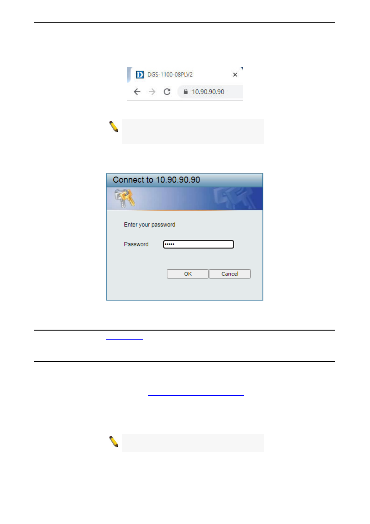
Accessing the Web-based Management Interface
In order to access the management interf ace, the PC must have an IP addres s in the same subnet as the
Switch. For example, if the Switch has an IP address of 10.90.90.90, th e PC should have an IP address of
77
Page 12
3 Getting Started D-Link Smart Managed Switch User Manual
10.x.y.z (where x/ y is a number between 0 and 254 and z is a num ber between 1 and 254), and a subnet
mask o f 255.0.0.0. To launc h the web inter fac e, sim ply open an y compatibl e web browser, enter 10.90.90.90
(the factory-default IP address) in the address bar, and press ENTER.
Figure 3.2 - Enter the IP address 10.90.90.90 in the web browser
NOTE: The Switch’s factory default IP addr ess is
10.90.90.90 with a subne t m ask of 255.0.0 .0 and
a default gateway of 0.0.0.0.
This will automatically load the web conf ig uration in your web browser.
When prompted to log in, enter the default password admin and press OK to continue.
Figure 3.3 - Logon Dialog Box
Web-based Management
Please refer to Chapter 4 Configuration for detailed instructions.
D-Link Network Assistant (DNA)
D-Link Network Assistant ( DNA) is a program that is used t o disco ver sw itches which are in the sam e La yer
2 network segment as your PC. You can download the DNA App from the D-Link official website.
1. Go to the D-Link official website at: https://tools.dlink.com/intro/dna/
2. Click the Free Download button to go the the Download window.
3. Click the Download button to download the DNA installer file to your local hard drive.
4. Run the DNA installer file and follow the on-screen instructions to complete the installation.
NOTE: Ref er to D-Link Network Assistant (DN A)
User Guide for more detail.
.
8
Page 13
4 Configuration D-Link Smart Managed Switch User Manual
If you close the web browser without
4 Configuration
The features and functio ns of the D-Link Sm art Managed Switch can be configur ed through the web-based
management interface.
Web-based Management
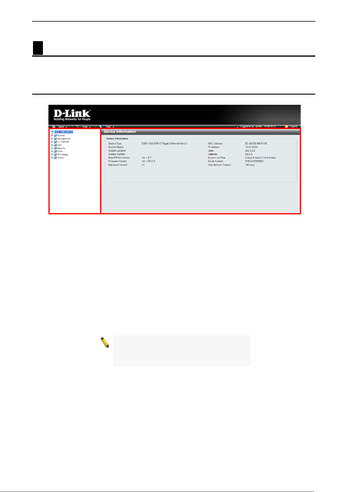
After a successful login you will see the screen below:
Function Tree
Main Configuration Window
Figure 4.1 - Web-based Management
The three main areas are the Tool Bar on top, the Function Tree on the lef t, and the M ain Configuration
Window.
The Tool Bar provides a quick and convenient way for accessing essential functions such as firmware
upgrades and basic settings.
When clicking a section or subsec tion in the f unction tr ee, all the settings of that section are disp layed in the
Main Configuration Window.
In the upper-right corner of the window, the current login user name and IP address are displayed.
Next to the IP address is the Logout button. Click this to end this session.
NOTE:
clicking the Logout button first, it will be seen as
an abnormal exit and the login session wi ll still be
occupied.
99
Page 14
4 Configuration D-Link Smart Managed Switch User Manual
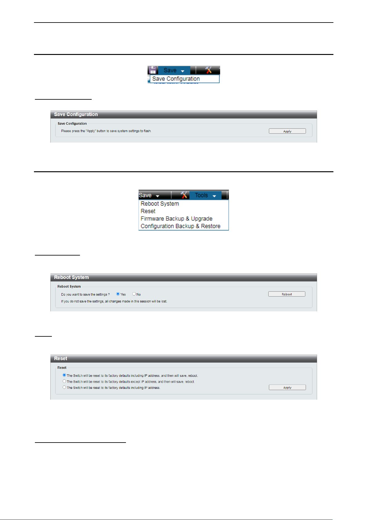
Tool Bar > Save
The Save Menu provides Save Configuration and Save Log functions.
Figure 4.2 - Save Menu
Save Configuration By clicking Apply, the current device configuration will be saved on the device’s flash memory.
Figure 4.3 - Save Configuration
Tool Bar > Tools
The Tool Menu provi des basic functions suc h as Reboot System, Reset, Firmware Back up and Upgrade,
and Configuration Backup and Restore.
Figure 4.4 - Tools Menu
Reboot System
This option provides a safe way to rebo ot the system. Click Yes to save the current sett ings or click No to
discard the current settings. Click Reboot to restart the Switch.
Figure 4.5 - Tools > Reboot System
Reset
Provide a safe res et option for the Switch. Dependi ng on the chosen reset option, s ome or all config uration
settings stored in the device’s flash memory will be reset to factory default.
Figure 4.6 - Tools > Reset
Select a suitable reset option and click Apply to make the configurations take effect.
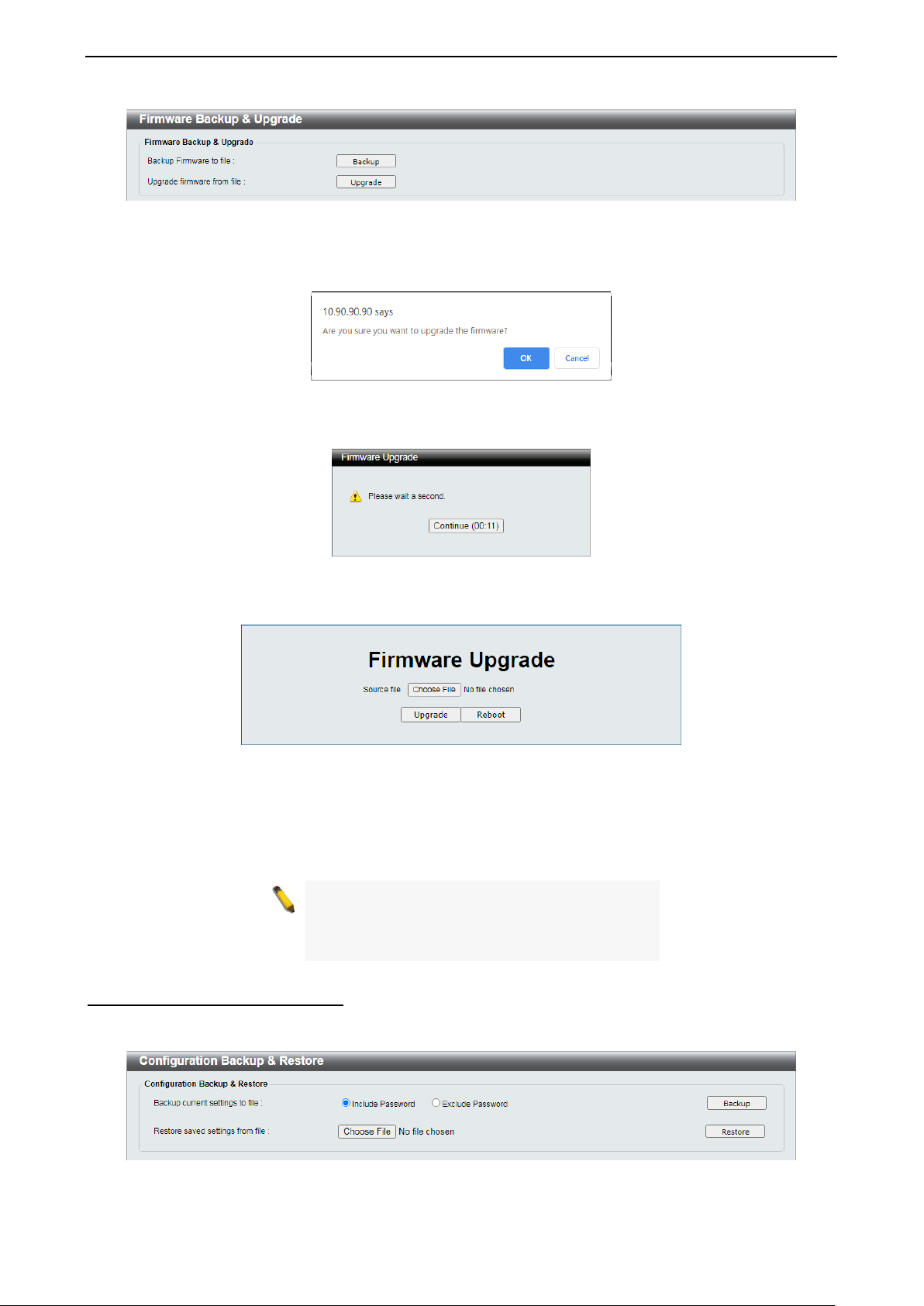
Firmware Backup and Upgrade
This windo w is used to create a back up of the device’s current firm ware, or upgrade the firmware using a
compatible firmware file.
10
Page 15
4 Configuration D-Link Smart Managed Switch User Manual
power cord from device until the upgrade
Figure 4.7 - Tools > Firmware Backup and Upgrade
Click Backup to save the firmware to your disk.
Click Upgrade to upgrade the firmware.
Figure 4.8 - Tools > Firmw are Backup and Upgrade - Confirm
Click OK to see the countdown timer window.
Figure 4.9 - Tools > Firmw are Backup and Upgrade - Countdown
When the countdown is over, the Switch enters the boot-loader mode.
Figure 4.10 - Tools > Firmware Backup and Upgrade - Upgrade
Click Choose File to browse for a compatible firmware file on your hard drive.
Click Upgrade to update the device’s firmware using the selected firmware file.
Click Reboot to cancel the firmware upgrade and reboot the device.
NOTE: Do not disconnect the PC or rem ove the
completes. The S witch may c rash if the firm ware
update is interrupted.
Configuration Backup and Restore
Allow the current configuration settings to be saved to a file, and if necessary, you can restore the
configuration settings from this file.
Figure 4.11 - Tools > Configuration Backup and Restore
1111
Page 16
4 Configuration D-Link Smart Managed Switch User Manual
Switch will reboot after restore, and all
Backup current settings to file: Specify to back up the current s ettings of the Switch with or without the
password, and click Backup.
Restore saved settings from file: Click Choose File to browse your inventories for a saved backup
settings file. Click Restore to backup settings file you want to restore.
NOTE:
current configurations will be overwritten.
Tool Bar > Help
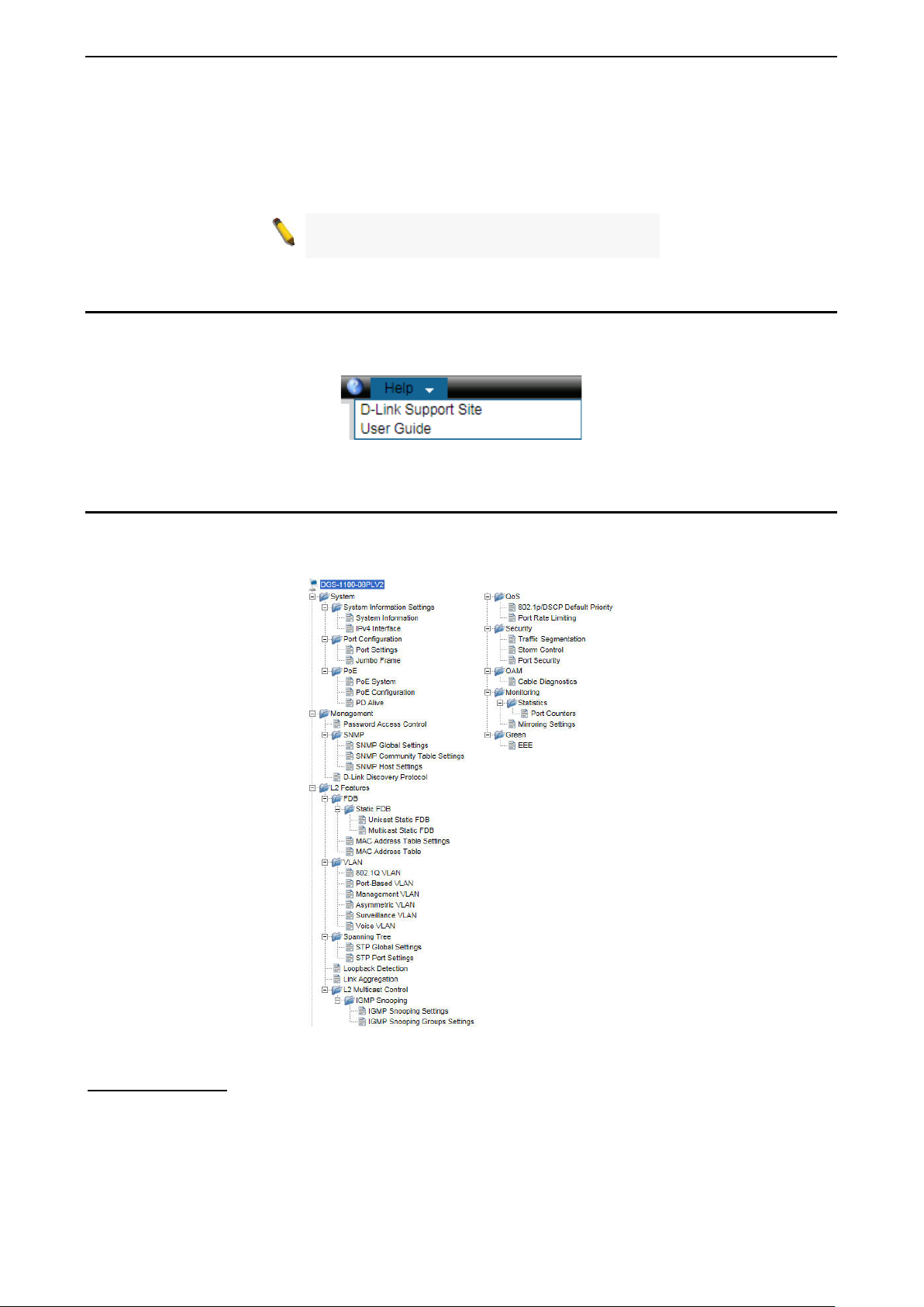
The Help Menu provides two ways of online support. D-Link Support Site leads to the D-Link website where
you can find online resources such as updated firmware images. User Guide can offer an immediate
reference for the feature definition or configuration guide.
Figure 4.12 - Online Help
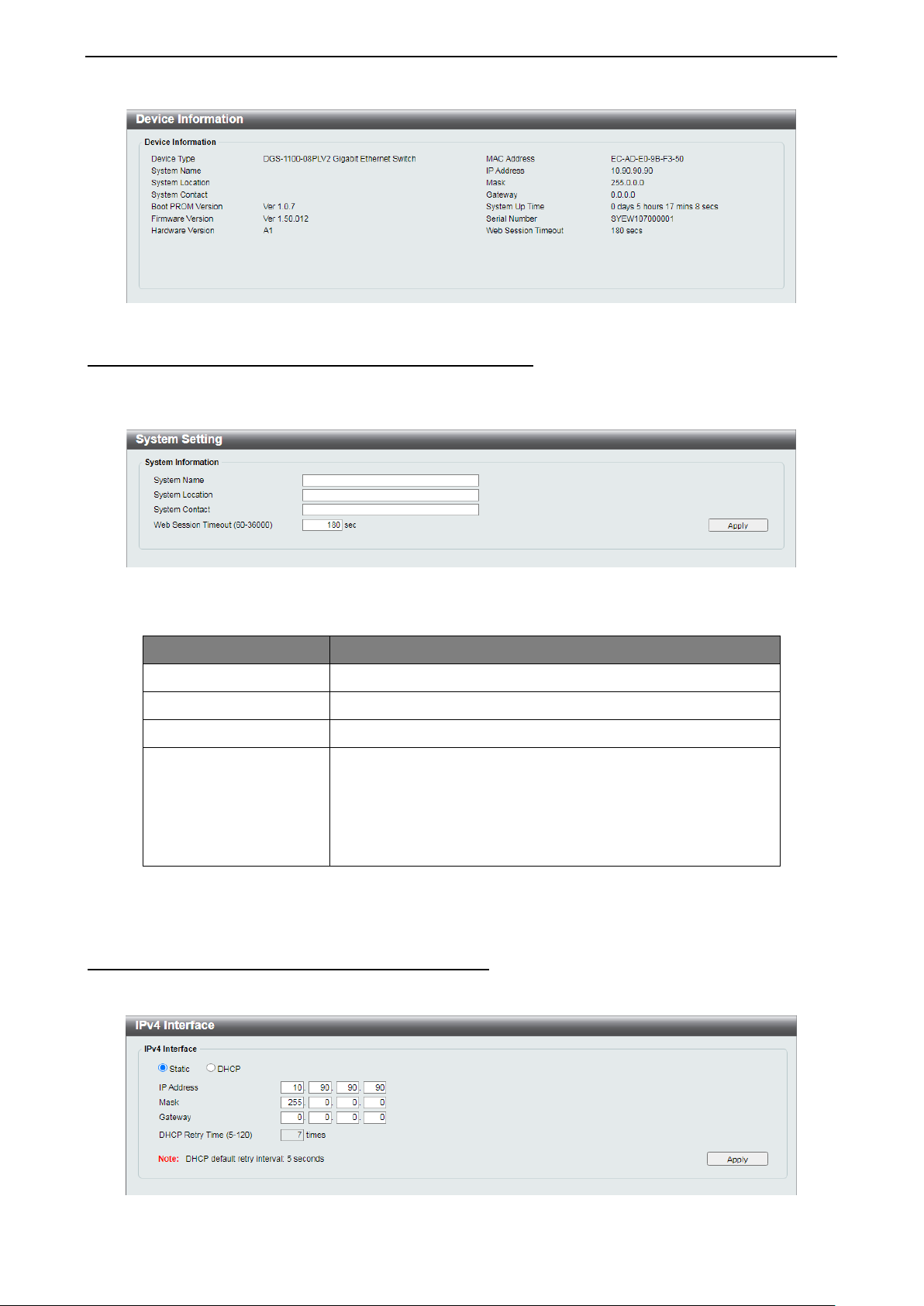
Function Tree
All configuration opt ions of the Switch are access ed through t he treeview on the left window. Click the setup
item that you want to configure. The follo wing sections provide a more detailed desc ription of each featur e
and function.
Figure 4.13 - Function Tree
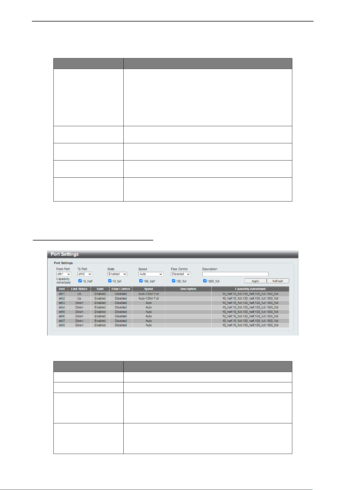
Device Information
The Device Information provides an overv iew of the Switc h, inc ludin g essen tial inf orm ation such as f irm ware
and hardware information, and IP addres s. Clicking DG S-1100-08PLV2 on top of the f unc tio n tr ee to s ee thi s
window.
12
Page 17
4 Configuration D-Link Smart Managed Switch User Manual
Web Session Timeout
activity in the web
. If the current
Figure 4.14 - Device Information
System > System Information Settings > System Information
The System Information allo ws the user to c onfigure t he basic s ystem information of the Switch . By e nte ring
the system inform ation, the Switch can more easily be r ec ogni zed f r om other Smart Managed devices o n th e
network.
Figure 4.15 - System > System Information Settings > System Information
The fields that can be configured are described below:
Item Description
System Name
System Location
System Contact
Specify the system name of the Switch.
Specify the system location of the Switch.
Specify the system contact of the Switch.
The Web Session T imeout controls the idle time-out period f or
security purposes, when there is no
interface within the specified time-out period
(60-36000)
session times out ( expires), the us er is required t o log into the
web management interface again. The range is from 60 to
36000 seconds, and the default setting is 180 seconds.
Table 4.1
Click Apply to make the configurations take effect.
System > System Information Settings > IPv4 Interface
The IPv4 Interface allows the user to configure the IP address and the basic system information of the
Switch.
Figure 4.16 - System > System Information Settings > IPv4 Interface
1133
Page 18
4 Configuration D-Link Smart Managed Switch User Manual
(Dynamic Host Configuration Protocol).
Specify the IPv4 address. By default, the IP address is
number of attempts to assign an IP address
duplex), 10 Mbps
You can enable this function to mitigate traffic congestion.
The fields that can be configured are described below:
Item Description
There are two ways for the Switch to obtain an IP address:
Static and DHCP
When using the static mode, the IP Address, Mask, and
Static/DHCP
Gateway can be m anually configured. When us ing the DHCP
mode, DHCP Retry Time can be manually configured. The
Switch will first lo ok for a DHCP ser ver to provide it with an IP
address (including net work mask and default gateway) bef ore
using the default.
IP Address
Mask
Gateway
DHCP Retry Time (5-
120)
10.90.90.90
Specify the subnet m ask of IP address. By default, th e subnet
mask is 255.0.0.0
Specify the gateway of IP addres s. By default, the gatewa y is
0.0.0.0
Specify the
through a DHCP server . The range is from 5 to 120 tim es, and
the default setting is 7 times.
Table 4.2
Click Apply to make the configurations take effect.
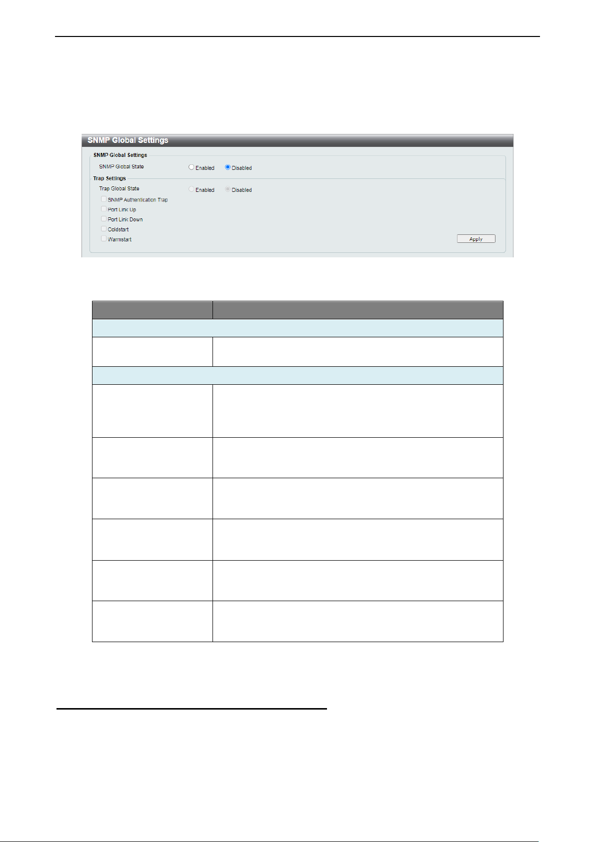
System > Port configuration > Port Settings
In Port Settings, the status of all ports can be monitored and configured.
Figure 4.17 - System > Port Configuration > Port Settings
The fields that can be configured are described below:
Item Description
From Port / To Port
State
Select a range of ports to be configured.
Enable or disable the specified ports.
Copper connections can op er ate i n For c ed M ode s e tti n gs 1000
Speed
Mbps (full-duplex), 100 Mbps (full/half(full/half-duplex), Auto, or Disabled. The default setting for all
ports is Auto.
Flow control
Ports configured for full-duplex use 802.3x flow control, halfduplex ports use back pressure flow con trol. The def ault setting
is Disabled.
14
Page 19

4 Configuration D-Link Smart Managed Switch User Manual
, these capabilities are
Be sure to adjust port speed settings
Manually configure the system power budget. The power
the next port attempting to power up is denied,
Description
Capability Advertised
Specify a description for the chosen ports
When the Speed is set to Auto
advertised during auto-negotiation.
Table 4.3
Click Apply to make the configurations take effect.
Click Refresh button to update the port status information.
NOTE:
appropriately after chan gin g the co nnect ed ca ble
media types.
System > Port Configuration > Jumbo Frame
D-Link Smart Managed Switches suppor t jumbo f rames (fram es larger than the Ethernet f rame size of 1536
bytes) of up to 9216 b ytes ( tagged) . T his func tion is d isabled b y def ault. Click Enabled and Apply to turn on
the jumbo frame support.
Figure 4.18 - System > Port Configuration > Jumbo Frame
System > PoE > PoE System
The PoE System window w ill display the PoE status including Syst em Budget Power, Support Total Power ,
Remainder Power, and the ratio of system power supply.
Figure 4.19 - System > PoE > PoE System
The fields that can be configured are described below:
Item Description
PoE System
PoE Power Threshold
budget range is between 7.1 and 80.0 Watts.
Defines the method used to deny power to a port once the
Power Shut Off
Sequence
threshold is reached. The options to choose from are:
• Deny nex t port: When the power budget is ex ceeded,
regardless of the port priority.
1155
Page 20

4 Configuration D-Link Smart Managed Switch User Manual
• Deny low pr iority port: The por t with the lower priority
Displays the percentage of system power supplied of the
Minimum Power Levels
Maximum Power Lev els a t
Guaranteed Output
Maximum Power
will be shut down to allow the higher priority port to
power up.
Legacy Support
System Power Status
Total PoE Power
Budget
Power Used
Power Left
The percentage of
system supplied
Click Apply to make the configurations take effect.
System > PoE > PoE Configuration
The Switch supports Powe r over Ethern et (PoE) as defined b y the IEEE specificatio n. The maxim um power
budget of the PoE ports is 30 W.
IEEE 802.3af defined that the PSE provides power according to the following classification:
Class Usage
0 Default 15.4 W 0.44 to 12.95 W
Specify to enable or disable detecting legacy PDs signal.
Displays the total PoE power budget of this switch.
Displays the current used power of the switch.
Displays the spare power of the switch.
switch.
Table 4.4
Output at the PSE
the PD
1 Optional 4.0 W 0.44 to 3.84 W
2 Optional 7.0 W 3.84 to 6.49 W
3 Optional 15.4 W 6.49 to 12.95 W
4 Optional Treat as Calss 0 Reserved for future use
IEEE 802.3at defined that the PSE provides power according to the following classification:
Class Usage PD Classification
Power by PSE
0 Default Default, Type 1 15.4 W 0.44 to 12.95 W
1 Optional Type 1 4.0 W 0.44 to 3.84 W
2 Optional Type 1 7.0 W 3.84 to 6.49 W
3 Optional Type 1 15.4 W 6.49 to 12.95 W
4 Optional Type 2 30 W 12.95 to 25.5 W
The PoE port table displays the Po E status including, State, Priority, Legacy Support, Power Limit, Power
(W), Voltage (V), Curr ent (mA), Classification, and Status. You c an s elect F rom Port / To Port t o con tr ol th e
PoE functions of a port.
Levels at the PD
16
Page 21

4 Configuration D-Link Smart Managed Switch User Manual
to configure PoE function for
negotiate and follow the classification from the PD power
For the PoE Port Settings table, if the
Figure 4.20 - System > PoE > PoE Configuration
The fields that can be configured are described below:
Item Description
From Port / To Port
State
Priority
Specify the PoE function of a port or ports.
Select enable or disable
designated port(s). Default is Enabled.
Configure the power suppl y priority as Low, High, or Critical
on designated port(s). Default is High.
This function allo ws you to m anuall y set t he por t po wer c urrent
limitation to be gi ven to the PD. Select f rom Class 1, Class 2,
Power Limit
Class 3, Class 4, or Auto for the power limit. Auto will
current based on the 802.3at standard.
Max. Wattage (1000-
30000)
Check the box and input the power budget to manua lly assign
an upper limit of port power budget on designated port(s).
Table 4.5
Click Apply to make the configurations take effect.
Click Refresh button to update the port PoE status infor mation.
NOTE:
classification was shown as “Legacy PD”, it will
be classified to non-AF PD or Legacy PD.
NOTE: The Switch conforms to IEEE 802.3af
and 802.3at standards . The IEEE PoE standar d
requires a switch to shut of f power to a port if the
power draw is less than 10mA within a 400ms
time interval. To support some non-standard
devices that may take longer, you may enable
this feature to ex tend the ti me interval to 500ms .
If the PD is still not po wering on, please cont act
the vendor of your device for support.
System > PoE > PD Alive
PD Alive function is a mechanism to de tec t PD hos t periodically. Once the P D h ost cann ot be r eac he d w ithin
the interval configured by administrator, then action would be executed .
1177
Page 22

4 Configuration D-Link Smart Managed Switch User Manual
Figure 4.21 - System > PoE > PD Alive
The fields that can be configured are described below:
Item Description
From Port / To Port
Specifies a port or ports.
PD Alive State Select enable or disable PD Alive function. Default is Disabled.
PD IP Address
Poll Interval
Retry Count
The field to enter the IP address of the PD host.
The time interval to check PD host. Default is 30 seconds.
The retry time for each polling action. Default is 2 times.
This parameter represents the time that the system will wait
Waiting Time
before restart to poll the PD host after a 'Reboot' action was
executed. Default Value is 90 seconds.
Action
The action desired to tak e when PD host is unreachable. The
default action is Reboot.
Table 4.6
Click Apply to make the configurations take effect.
Click Refresh button to update the inform ation.
Management > Password Access Control
The Password Access Control window allows the user to configure the access password of the Switch.
Figure 4.22 - Management > Password Access Control
The fields that can be configured are described below:
Item Description
Old Password
New Password
Confirm Password
Enter the old password of the Switch.
Enter the new password of the Switch.
Enter the new password of the Switch again.
Table 4.7
Click Apply to make the configurations take effect.
Management > SNMP > SNMP Global Settings
Simple Network Management Protocol (SNMP) is an OSI Layer 7 (Application Layer) protocol designed
specifically for managin g and monitoring network devices. SNMP enables net work management stations to
18
Page 23
4 Configuration D-Link Smart Managed Switch User Manual
SNMP Authentication
Check this feature to enable authentication traps. When a
Check this feature to enable Link Down traps. Whenever a
Check this feature to have client devices send an SNMP
notification to the management station when performing a
read and modify the settin gs of gateways, routers, switches, and other net works. Use SNMP to configure
system features for proper operation, monitor performanc e and detect potential problems in the Switch or
LAN.
This panel allows th e user to configure the SNMP settings, used for managing and monitor devices on the
network.
Figure 4.23 - Management > SNMP > SNMP Global Settings
The fields that can be configured are described belo w:
Item Description
SNMP Global Settings
SNMP Global State
Trap Settings
Trap Global State
Trap
Port Link Up
Port Link Down
Coldstart
Specify to enable or disable the SNMP feature. The default
setting is Disabled.
Enable or disable SN MP trap notifications f rom client devices.
Disabling this option m eans no trap signa ls will be sent. W hen
enabling this option, you may choose the type of SNMP traps
to enable.
client device fails to authenticate with the SNMP server, and
authentication trap will be sent to the management station.
Check this feature to enab le Li nk U p traps. Whenever a device
changes status from ‘link down’ to ‘link up’, it will send a Li nk
Up trap to the management station.
device changes stat us f r om ‘link up’ to ‘link down’, it wi l l s en d a
Link Down trap to the management station.
Check this feature to have client devices send an SNMP
notification to the m anagem ent station when performing a cold
start.
Warmstart
warm start.
Table 4.8
Click Apply to make the configurations take effect.
Management > SNMP > SNMP Community Table Settings
This window is used to create an SNMP community string to define the relationship between the SNMP
manager and an agent. The community string acts like a password to permit access to the agent on the
Switch.
1199
Page 24

4 Configuration D-Link Smart Managed Switch User Manual
SNMP community members can read
from, and write to the contents of the MIBs on the
is used like a password to give remote SNMP managers
based Security
Specify the security model. The options to choose from are
Figure 4.24 - Management > S NMP > SNMP Community Table Settings
The fields that can be configured are described below:
Item Description
Select the access r ight here. O ptions to c hoose from are Read
Only, and Read Write.
• Read Write -
Access Right
Switch.
• Read Only - SNMP community members can only read
the contents of the MIBs on the Switch.
Enter an alphanumeric string of up to 32 characters that is
Community Name
used to identify m embers of an SNMP communit y. This string
access to MIB objects in the Switch’s SNMP agent.
Table 4.9
Click Apply to create a new SNMP community.
Management > SNMP > SNMP Host Settings
This window is used to configure the recipients of the SNMP notific atio ns.
Figure 4.25 - Management > SNMP > SNMP Host Settings
The fields that can be configured are described below:
Item Description
Host IPv4 Address
Specify the IPv4 address of the SNMP management host.
UserModel
Community String
SNMPv1 and SNMPv2c.
Specify the community string for the management host.
Table 4.10
Click Apply to make the configurations take effect.
Management > D-Link Discovery Protocol
For devices that s upport the D -Link Disc over y Prot ocol ( DD P), t his window allows users to enable or disable
DDP, and configure the DDP packet report timer.
20
Page 25

4 Configuration D-Link Smart Managed Switch User Manual
Link discovery
Link Discover Protocol in
The selection of the port number on which the MAC address
N ID of the VLAN which the corresponding MAC
Figure 4.26 - Management > D-Link Discovery Protocol
The fields that can be configured are described below:
Item Description
DProtocol State
Specify to enable or dis a bl e th e D -L ink discovery protocol f eat ur e of
the Switch.
Configure the report timer of the D-
Report Timer
seconds. The values are 30, 60, 90, 120 or Never. The def ault is
Never.
Table 4.11
Click Apply to make the configurations take effect.
L2 Features > FDB > Static FDB > Unicast Static FDB
The Unicast Static F DB window allows user to view and conf igure the static unicast forwarding settings o n
the Switch.
Figure 4. 27 - Features > FDB > Static FDB > Unicast Static FDB
The fields that can be configured are described below:
Item Description
Port / Drop
entered resides. This opti on could also drop t he MAC address from
the unicast static FDB. W hen selecting Port, se lect the switch port
number.
Port Number
VID
MAC Address
Select the port number used here, when Port is selected in the
previous drop-down lis t.
Enter the VLA
address belongs to.
Enter the MAC addr es s to whic h packets will be static ally forwarded
or dropped. This must be a unicast MAC address.
Table 4.12
Click Apply to make the configurations take effect.
Click Delete All to delete all the entries found in the display table.
Click Delete to remove the corresponding entry.
L2 Features > FDB > Static FDB > Multicast Static FDB
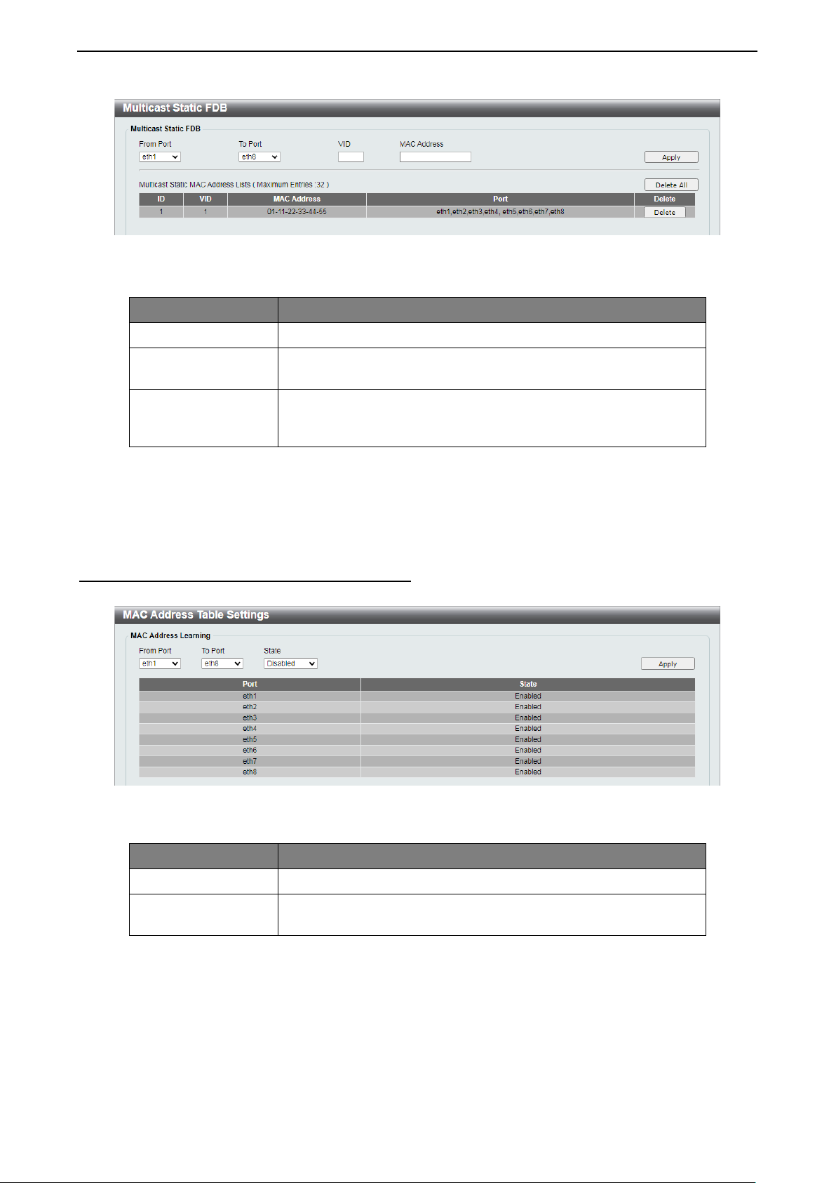
This window allows user to view and configure the static multicast forwarding settings on the Switch.
2211
Page 26
4 Configuration D-Link Smart Managed Switch User Manual
rmat of the
Figure 4. 28 - L2 Features > FDB > Static FDB > Multicast Static FDB
The fields that can be configured are described below:
Item Description
From Port / To Port
VID
Select the appropriate port range used for the configuration.
Enter the VLAN ID of the VLAN which the corresponding MAC
address belongs to.
Enter the static destinatio n MAC address of the multic ast pack ets.
MAC Address
This must be a multicast MAC address. The fo
destination MAC address is 01-XX-XX-XX-XX-XX.
Table 4.13
Click Apply to make the configurations take effect.
Click Delete All to delete all the entries found in the display table.
Click Delete to remove the corresponding entry.
L2 Features > FDB > MAC Address Table Settings
This window allows user to view and configure the MAC address learning function.
Figure 4.29 - L2 Features > FDB > MAC Address Table Settings
The fields that can be configured for MAC Address Learning are described below:
Item Description
From Port / To Port
State
Select the appropriate port range used for the configuration.
Specify to enable or disable the MAC address lear ning function.
The default is Enabled.
Table 4.14
Click Apply to make the configurations take effect.
22
Page 27
4 Configuration D-Link Smart Managed Switch User Manual
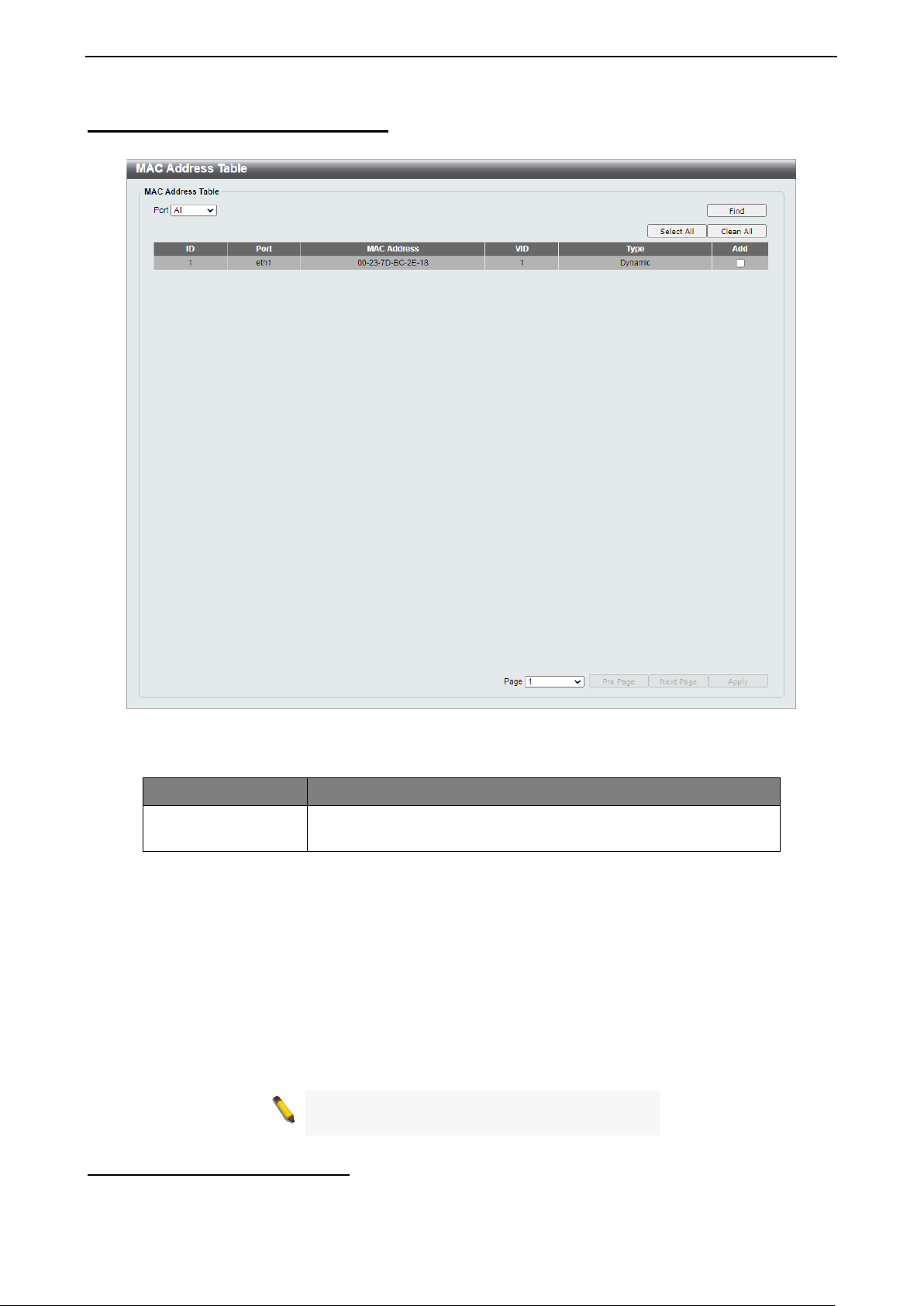
L2 Features > FDB > MAC Address Table
This window is used to view the entries listed in the MAC address table.
Figure 4.30 - L2 Features > FDB > MAC Address Table
The fields that can be configured are described below:
Item Description
Port
Select a single por t or all por ts. The i nform ation for th e port( s) will
be displayed in the information table.
Table 4.15
Click Find to locate a specific entry based on the information entered.
Click Select All to select up to 32 dynamic MAC addresses.
Click Clean All to clear the selected dynamic MAC addresses.
Click the Corresponding check box(es) in the Add column to select the specific dynamic MAC address(es).
Select the page number in the Page drop-do w n lis t to navigate to a specific page when multiple pages exist.
Click Pre Page to go to the previous page when multiple pages exist.
Click Next Page to go to the next page when multiple pages exist.
Click Apply to add the selected dynamic MAC address(es) to unicast static FDB.
NOTE: When viewing the different FDB pages,
the device will take a moment to refresh the UI.
L2 Features > VLAN > 802.1Q VLAN
A Virtual Local Area Network (VLAN) is a group of ports that can be anywhere in the network, but
communicate as though they were in the same area.
2233
Page 28

4 Configuration D-Link Smart Managed Switch User Manual
VLANs can be eas ily or gan ized to ref lect department groups (such as R &D, Mark eting), usage gro ups (s uch
as e-mail), or m ulticast groups (multim edia applications such as video conf erencing), and therefore help t o
simplify network management by allo wing users to move devices to a n ew VLAN without having to chang e
any physical connections.
This window provides powerful VID management functions. The original settings have the VID as 1, no
default name, and all ports as “Untagged”.
Figure 4.31 - L2 Features > VLAN > 802.1Q VLAN
Click Rename to rename the VLAN group.
Click Delete to remove the VLAN group.
To create a new VLAN group, click Add VID and the following will be displayed:
Figure 4.32 - L2 Features > VLAN > 802.1Q VLAN - Add VID
The fields that can be configured for 802.1Q VLAN are described below:
Item Description
VID
VLAN Name
Port
Enter the VID to be created.
Enter the VLAN name for the VID to be created.
Assign ports as Untagged, Tagged or Not Member. Click All to
select all ports.
Table 4.16
Click Apply to create a new VLAN group.
To configure the PVID settings, click PVID settings and the following will be displayed:
Figure 4.33 - L2 Features > VLAN > 802.1Q VLAN - PVID Settings
Click Apply to make the configurations take effect.
Click Back to discard any changed made and return to the previous window.
To edit an existing VLAN group, click the VID hyperlink and the following will be displayed:
24
Page 29
4 Configuration D-Link Smart Managed Switch User Manual
set to
The Surveillance VLAN, Voice VLAN
and Management VLAN will be disabled. The
settings of IGMP Snooping and MAC Address
Figure 4.34 - L2 Features > VLAN > 802.1Q VLAN – Edit VID
Click Apply to make the configurations take effect.
Click Previous Page to discard any changed made and return to the previous page.
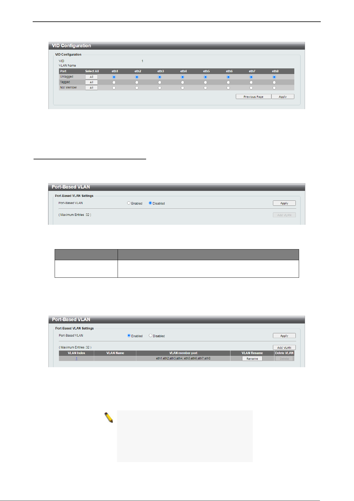
L2 Features > VLAN > Port-Based VLAN
Port-Based VLANs are the simplest and most common form of VLAN. It assigns physical LAN ports to
VLANs, ef fectively broadening their ap plication. You can assign multip le ports to the same VLAN, or eac h
port to a separate VLAN.
Figure 4.35 - L2 Features > VLAN > Port-Based VLAN
The fields that can be configured are described below:
Item Description
Port-Based VLAN
Select to enable or disable the Port-Based VLAN function. The
default is Disabled.
Table 4.17
Click Apply to make the configurations take effect.
To enable the Port-Based VLAN function, click Enabled and Apply, and the following will be displayed:
Figure 4.36 - L2 Features > VLAN > Port-Based VLAN - Enabled
Click Rename to rename the VLAN group.
Click Delete to remove the VLAN group.
NOTE: W hen Port-Based VLAN is enabled, the
802.1Q VLAN and the Traffic Segmentation will
be disabled and their settings will be re
default.
Table will be reset to default.
2255
Page 30
4 Configuration D-Link Smart Managed Switch User Manual
When 802.1Q Management VLAN is
enabled, the 802.1Q VLAN should be enabled
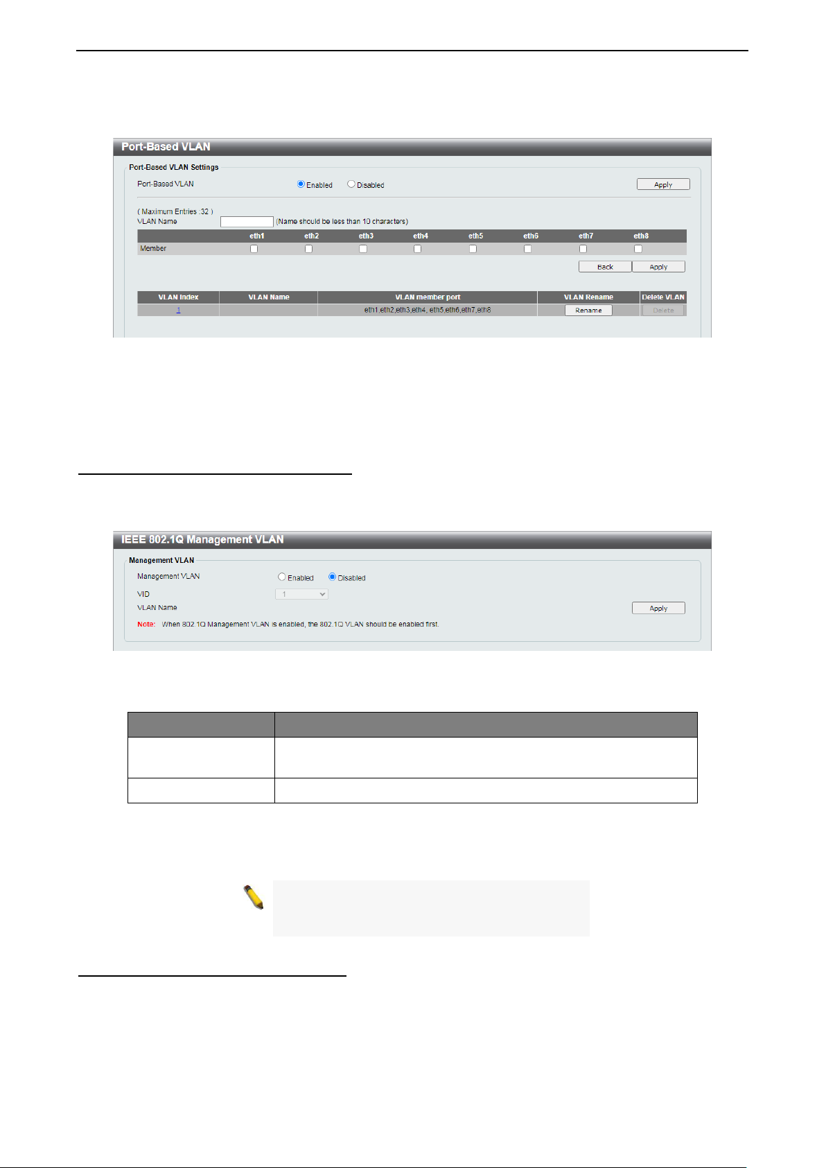
To create a new Port-Based VLAN group, click Add VLAN and the following will be displayed:
Figure 4.37 - L2 Features > VLAN > Port-Based VLAN - Add
Enter the VLAN Name and select the Member port to be created.
Click Apply to make the configurations take effect.
Click Back to discard any changed made and return to the previous window.
L2 Features > VLAN > Management VLAN
The 802.1Q Management VLAN is used to transfer management authority of the switch from the default
VLAN to another VLAN. This allows for more flexible network management. There can only be one
management VLAN at a time when this function is enabled.
Figure 4.38 - L2 Features > VLAN > Management VLAN
The fields that can be configured are described below:
Item Description
Management VLAN
VID
Select to enable or disable the Managem ent VLAN function. The
default is Disabled.
Select the VID to act as the managing VLAN.
Table 4.18
Click Apply to make the configurations take effect.
NOTE:
first.
L2 Features > VLAN > Asymmetric VLAN
The Asymmetric VLAN allows for a more efficient use of shared resources, such as server or gateway
devices.
26
Page 31
4 Configuration D-Link Smart Managed Switch User Manual
Figure 4.39 - L2 Features > VLAN > Asymmetric VLAN
The fields that can be configured are described below:
Item Description
Asymmetric VLAN
State
Specify to enable or disable the As ymmetric VLAN of the Switch.
The default value is disabled.
Table 4.19
Click Apply to make the configurations take effect.
L2 Features > VLAN > Surveillance VLAN
Surveillance VLAN is a feature that allows you to place the video traffic from D-Link IP cameras to an
assigned VLAN to enhance the IP surveillance service. With a higher priority and individual VLAN, the quality
and the security of sur veillance tr affic are guaranteed. The Surve illance VLAN f unction will check the sourc e
MAC address on the incoming packets. If it matches the specified MAC address, the packets will pass
through with desired priority.
This window is used to configure the Surveillance VLAN settings.
2277
Page 32

4 Configuration D-Link Smart Managed Switch User Manual
by default. There are another five surveillance
be configured for surveillance VLAN.
nd VMS
lients are necessary components for an IP surveillance
Figure 4.40 - L2 Features > VLAN > Surveillance VLAN
The fields that can be configured are described below:
Item Description
Surveillance VLAN Global Settings
Surveillance VLAN
VLAN ID
Priority
Specify to enable or disable the Surveillance VLAN function.
The default value is disabled.
Specify the VLAN ID to act as the Surveillance VLAN.
Specify the priorit y level. The levels of pri ority are from 0 to 7.
The default priority is 5.
User-defined MAC Settings
Surveillance VLAN will automatically detect D-Link surveillance
devices
components that can
Component Type
These five components are Video Management Server
(VMS), VMS Client, Video Encoder, Network Storage, and
Other IP Surveillance Devices. Usually, VMS a
c
service.
Description
MAC Address
Enter a description for the component.
Enter a MAC address of the component.
Table 4.20
Click Apply to make the configurations take effect.
Click Add to create a new device for Surveillance VLAN.
Click Delete to remove the Surveillance VLAN entry.
L2 Features > VLAN > Voice VLAN
Voice VLAN is a feature that allows you to place the voice traffic from D-Link IP phones to an assigned VLAN
to enhance the IP voic e service. With a higher prior ity and individual VLAN, the qua lity and the security of
voice traffic ar e guaranteed. The V oice VLAN functio n will check the sourc e MAC address on t he incoming
packets. If it matches the spec if ied MAC address, the packets will pass through with desired priority.
28
Page 33

4 Configuration D-Link Smart Managed Switch User Manual
including 3COM, Cisco, Veritel, Pingtel, Siemens,
The user can manually create a Telephony OUI with a
Figure 4.41 - L2 Features > VLAN > Voice VLAN
The fields that can be configured are described below:
Item Description
Voice VLAN Global Settings
Voice VLAN
VLAN ID
Priority
Specify to enable or disable the Voice VLAN function.
Specify the VLAN ID to act as a Voice VLAN.
Specify the priorit y level. The levels of pri ority are from 0 to 7.
The default priority is 5.
OUI Settings
Pre-defined Organizationally Unique Identifier (OUI) values,
Default OUI
NEC/Phillips, Huawei3COM, and Avaya.
User-defined OUI
description. The maximum number of user-defined OUIs is 5.
Table 4.21
Below is a list of the pre-defined voice OUI’s. These cannot be used as a user-defined OUI.
OUI Vendor Mnemonic Name
00:E0:BB 3COM 3com
00:03:6B Cisco cisco
00:E0:75 Veritel veritel
00:D0:1E Pingtel pingtel
00:01:E3 Siemens siemens
00:60:B9 NEC / Philips nec&Philips
00:0F:E2 Huawei-3COM Huawei&3com
00:09:6E Avaya avaya
Table 4.22
Click Apply to make the configurations take effect.
Click Add to create a new device for Voic e VLAN.
Click Delete to remove the Voice VLAN entry.
2299
Page 34

4 Configuration D-Link Smart Managed Switch User Manual
Select to enable or disable the STP topology change trap
L2 Features > Spanning Tree > STP Global Settings
The Switch im plements two versions of the Spanning Tree Protocol: Rapid Spanning T ree Protocol (R STP)
as defined by IEEE 802.1 w, a versi on com patib le with the I EEE 802.1D ST P. RS TP c an operat e with leg acy
equipment implementing IEEE 802.1D, however the advantages of using RSTP will be lost.
By default, Rapid Spannin g Tree is disabled. If enabled, the S witch will listen for Bridge Protoco l Data Unit
(BPDU) packets and their accompan ying Hello Pack ets. T he BPDU pack ets are s ent eve n if a BP DU pac k et
is not received. Ther efore, each connection between bridg es is sensitive to the status of the link. Ultim ately
this difference results in faster detection of failed links, and therefore faster topology adjustment.
Figure 4.42 - L2 Features > S panning Tree > STP Global Settings
The fields that can be configured are described below:
Item Description
Spanning Tree State
Spanning Tree State
Select to enable or disable the Spanning Tree Protocol.
Spanning Tree Mode
Spanning Tree Mode
Select the STP mode. The options to choose from are RSTP
and STP.
STP Traps
STP New Root Trap
Select to enable or disable the STP new root trap option.
STP Topology Change
Traps
option.
Table 4.23
Click Apply to make the configurations take effect.
L2 Features > Spanning Tree > STP Port Setting s
STP can be set u p per por t. In addition to s etting S panning Tree param eters for us e on the switch level, t he
Switch a llows configuration of a spanning tree setup for a group of ports. Each p ort group spann ing tree will
require separate configuration.
An STP Group spanning tree works in the sam e way as the switch-level s panning tree, but the r oot bridge
concept is replaced wit h a root port conce pt. The root por t is selected base d on the priorit y of and path cost
to the port. Redundant links will be blocked, just as redundant links are blocked on the switch level.
The STP on the switch l evel blocks redundant links between switc hes (and similar network devices). T he
port level STP will block redundant links within an STP Group
30
Page 35

4 Configuration D-Link Smart Managed Switch User Manual
hoose from are
change to the
up occurs
Figure 4.43 - L2 Features > Spanning Tree > STP Port Settings
The fields that can be configured are described below:
Item Description
From Port / To Port
Select the range of ports to be incl uded in the spanning tree port
group.
Select the Port Fast option here. Options to c
Network, Disabled, and Edge.
• In the Network mode, the port will r em ain in t he no n-port-
fast state for three seconds. The port will change to the
port-fast state if no BPDU is received and changes t o the
forwarding state. If t he port received the BPDU later , it will
change to the non-port-fast state.
Port Fast
• In the Disabled m ode, the port will always be in th e non-
port-fast state. It will always wait for the forward-time
delay to change to the forwarding state.
• In the Edge mode, the port will directly
spanning-tree forwarding state when a linkwithout waiting for the f orward-time delay. If the interfac e
receives a BPDU lat er, its operation s tate changes to the
non-port-fast state. The default option is Network.
Table 4.24
Click Apply to make the configurations take effect.
Click Refresh to renew the window.
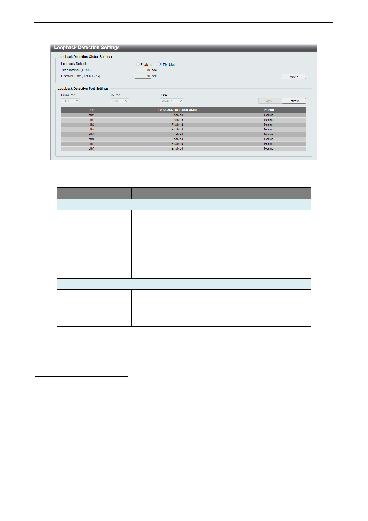
L2 Features > Loopback Detection
The Loopback Detection function is used to detect loops created by a specific port while Spanning Tree
Protocol (STP) is not enabled in the network, especially when the down links are hubs or unmanaged
switches. The Switch will automatically shut down the port. The looping port will be unlocked when the
Loopback Detection Recover Time times out. Loop back Detection can also be enab led or disabled for a
specified range of ports simultaneously.
3311
Page 36
4 Configuration D-Link Smart Managed Switch User Manual
will disable the
Select the range of ports to enable or disable Loopback
Figure 4.44 - L2 Features > Loopback Detection Settings
The fields that can be configured are described below:
Item Description
Loopback Detection Global Settings
Loopback Detection
Time Interval (1-255)
Specify to enable or disab le loopback detection function. The
default is Disabled.
Set a Loop detection Interv al betwee n 1 and 255 s eco nds. T he
default is 10 seconds.
Time allowed (in seconds) for recovery when a Loopback is
Recover Time (0 or 60-
255)
detected. The Loop Detection Recover Time can be set at 0
seconds, or 60 to 255 seconds. Entering 0
Loop Detection Recover Time. The default is 60 seconds
Loopback Detection Port Settings
From Port / To Port
State
Detection for.
Enable or disable Loo pback Detection for the specifie d range
of ports.
Table 4.25
Click Apply to make the configurations take effect.
Click Refresh to renew the Loopback Detection table.
L2 Features > Link Aggregation
The Link Aggregation f unction enables the com bining of two or more ports toge ther to increase bandwidt h.
Each Link Aggregation group supports a maximum of four ports.
32
Page 37

4 Configuration D-Link Smart Managed Switch User Manual
Figure 4.45 - L2 Features > Link Aggregation
The fields that can be configured f are described below:
Item Description
Link Aggregation Global Settings
Link Aggregation
Specify to enable or disable the Link Aggregation function.
Channel Group Information
ID
Port
Select a link aggregation group.
Select the ports to assign to the aggregation group.
Table 4.26
Click Apply to make the configurations take effect.
Click Delete to remove the Link Aggregation group.
NOTE: Each combined port must be c onnected
to devices within the same VLAN group.
L2 Features > L2 Multicast Control > IGMP Snooping > IGMP Snooping Settings
With Internet Group Management Protocol (IGMP) snooping, the Smart Managed Switch can make
intelligent multicast forwarding decisions by examining the contents of each frame’s Layer 2 MAC header.
By default, IGMP is disabled. If enabled, the Smart Managed Switch can recognize IGMP queries and
reports sent between network stations or devices and an IGMP host. With IGMP snooping enabled, the
Smart Managed Switch will forward multicast traffic only to the connections that requested it.
Figure 4.46 - L2 Features > L2 Multicast Control > IGMP Snoopin g > IGMP Sno opi ng Settings
The fields that can be configured for are described below:
Item Description
IGMP Snooping
Specify to enable or d is ab l e the IG M P S no oping function of the
Switch.
Table 4.27
3333
Page 38

4 Configuration D-Link Smart Managed Switch User Manual
Click Apply to make the configuration take effect.
L2 Features > L2 Multicast Control > IGMP Snooping > IGMP Snooping Group Settings
The IGMP Snooping Group Settings window allows user to configure IGMP snooping static groups and
display IGMP snooping groups on the Switc h.
Figure 4.47 - L2 Features > L2 Multicast Control > IGMP Snooping > IGMP Snooping Grou p Set tings
The fields that can be configured for are described below:
Item Description
IGMP Snooping Static Group Settings
VID
Group Address
From Port / To Port
Specify the VLAN ID to create the IGMP group.
Specify the group IP address for the IGMP Snooping group.
Specify a range of ports to be i ncluded in the IGMP Snooping
group.
Table 4.28
Click Add to create a new IGMP Sno opi ng group .
Click Delete to remove the corresponding IGMP Snooping group.
Click Delete All to remove all IGMP Snooping groups.
Click Refresh to renew the IGMP Snooping Groups Table information.
QoS > 802.1p/DSCP Default Priority
Quality of Service (QoS) is an implementation of the IEEE 802.1p standard that allows network
administrators to manage traffic f or important functions that req uir e more bandwidth or ha ve a higher pr iorit y,
such as VoIP (voice-over Internet Protocol), web browsing applications, file server applications, or video
conferencing. Thus with larger bandwidth, less c ritical traffic is limited, an d therefore excessive band width
can be saved.
The following figure dis plays the status of Quality of Service pr iority levels of each port. This means that the
Switch will handle traff ic from higher priorit y ports f irst. For pack ets that ar e unta gged, th e Switc h w ill ass ign
the priority depending on your configuration.
34
Page 39

4 Configuration D-Link Smart Managed Switch User Manual
traffic based on the 802.1p priority in the VLAN tag or the
header. Only one mechanism is selected to prioritize the
highest queue to be emptied first while the other
to handle packets in an even distribution among
Figure 4.48 - QoS > 802.1p/DSCP Default Priority – 802.1p
Figure 4.49 - QoS > 802.1p/DSCP Default Priority – DSCP
The fields that can be configured are described below:
Item Description
Global Settings
D-Link Smart Managed Switc h allows the user to prior itize the
Select QoS mode
DSCP (Differentiated Services Code Point) priority in the IP
packets at a time.
Specify the queuing mechanism, the option are:
• Strict Pri ority: Denoting a Strict scheduling will set the
Queuing mechanism
queues will follow the weighted ro und-robin sc hedulin g
scheme.
• WRR: Us e the weighted round-robin (WRR) alg orithm
3355
Page 40

4 Configuration D-Link Smart Managed Switch User Manual
priority classes.
This configures the transfer speed limit for
This configures the transfer speed limit for
IEEE 802.1p Default Priority Settings
From Port / To Port
Specify a range of ports to be configured.
Defines the priority level for the corresponding port. The priority
Priority
range is between 0 and 7 with 0 being assigned to the lowest
priority and 7 assigned to the highest.
DSCP Priority Settings
From DSCP Valu e / To
DSCP Value
Specify a range of DSCP values to be configured.
Defines the priority level for the corresponding port. The priority
Priority
range is between 0 and 7 with 0 being assigned to the lowest
priority and 7 assigned to the highest.
Table 4.29
Click Apply to make the configurations take effect.
QoS > Port Rate Limiting
This window is used to configure the transfer speed limit for a selection of ports.
Figure 4.50 - QoS > Port Rate Limiting
The fields that can be configured are described below:
Item Description
From Port / To Port
Specify a range of ports to be configured.
Select the direction option. Options to choose from are:
• Input:
ingress traffic.
Direction
• Output:
egress traffic.
• Both: This conf igures the transfer s peed limit for both
ingress and egress traffic.
Rate Limit
Specify the rate lim it in kbps or Mbps. Or specif y No Limit to
remove the rate limit.
Table 4.30
Click Apply to make the configurations take effect.
Security > Traffic Segmentation
This feature allows adm inistrators to distribute t raffic flow from a single por t to a group of ports on a singl e
Switch. This met hod of segmenting the flow of t raffic is similar to using VLA Ns to limit traffic, but is m ore
restrictive.
36
Page 41

4 Configuration D-Link Smart Managed Switch User Manual
From Forward Port /
Specify the type of controlled packets, Options are Broadcast
Unknown Unicast.
If Storm Control is enabled, the Switch will start dropping
The threshold ranges from 8 to 1,000,000 kbps.
Figure 4.51 - Security > Traffic Segmentation
The fields that can be configured are described below:
Item Description
From Port / To Port
To Forward Port
Specify a range of ports to be configured as sources ports.
Specify a range of ports to be configured as forwarding ports.
Table 4.31
Click the Add button to add a new entry.
Click the Delete button to remove an entry based on the information entered.
Security > Storm Control
The Storm Control feature provides the ability to control the receive rate of broadcast, multicast, and
unknown unicast pac kets. Once a packet storm has been detected, the Switch will drop incoming packets
until the storm has subsided.
Figure 4.52 - Security > Storm Control
The fields that can be configured are described below:
Item Description
Storm Control Status
Storm Control
Threshold (8-1000000)
Specify to enable or disable the storm control function.
Only, Multicast & Broadcast, and Multicast & Broadcast &
packets of the specified type when exceeding this threshold.
Click Apply to make the configurations take effect.
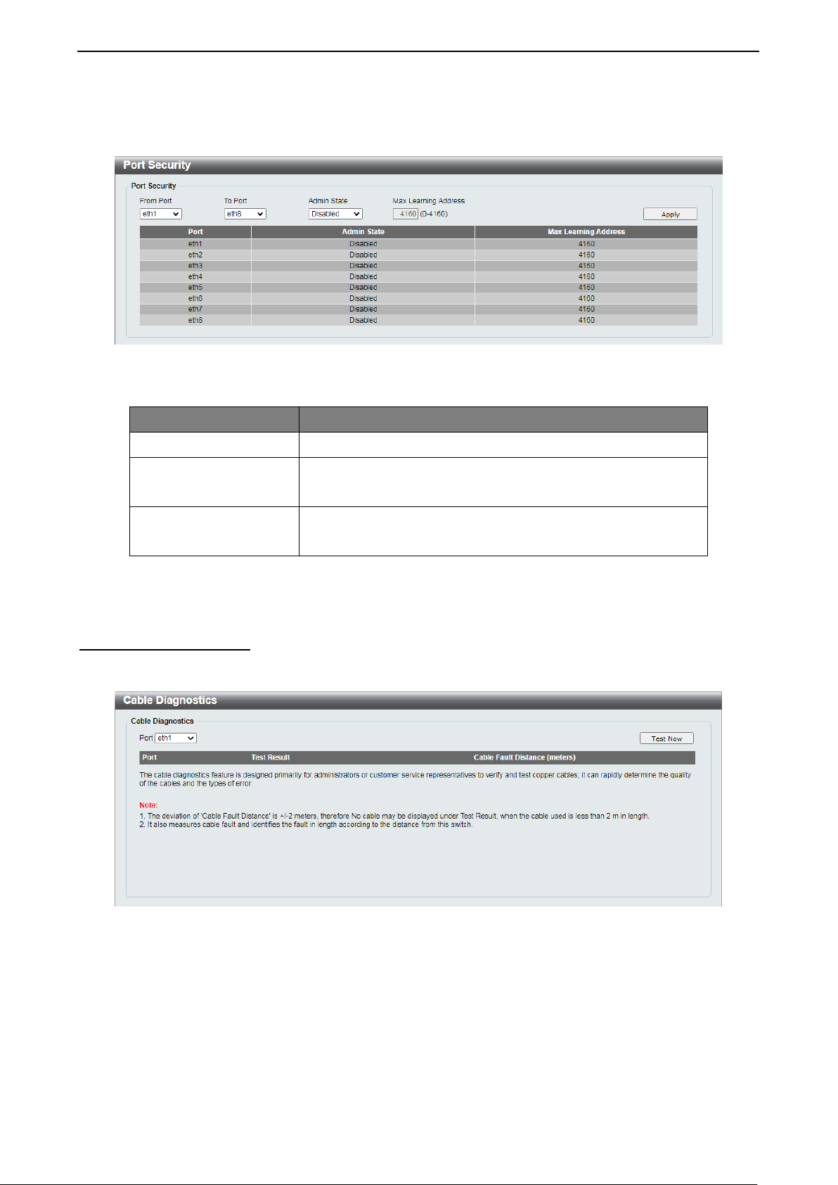
Security > Port Security
Port Security im proves network sec urity by restricting access on a specific port only to user s with a spec ific
MAC address.
Table 4.32
3377
Page 42
4 Configuration D-Link Smart Managed Switch User Manual
Select Enabled to lock down t he port and the ass ociated MAC
corresponding port(s).
Define the maximum number of MAC addresses that can be
4160.
Ports can be locked to pre vent users from m odifying the MAC address forwarding table. Lock ing ports also
prevents additional MAC addresses from being learned.
Figure 4.53 - Security > Port Security
The fields that can be configured are described below:
Item Description
From Port / To Port
Admin State
Max Learning Address
Specify a range of ports to be configured.
address table. Selec t Disabled to dis able Port Secur ity on the
associated with the c orresponding port. This ranges from 0 to
Table 4.33
Click Apply to make the configurations take effect.
OAM > Cable Diagnostics
The Cable Diagnostics is designed primarily for administrators and customer service representatives to
quickly examine the quality of copper cables, recognize the cable type, and detect cable errors.
Figure 4.54 - OAM > Cable Diagnostics
Select a port and then click the Test Now button to start the diagnosis. The results will be displayed below:
38
Page 43

4 Configuration D-Link Smart Managed Switch User Manual
there is an unintended
connection between two or more conductors in the
broken or the other end of the cable is simply
and error occurred during the
Cable Fault Distance
Indicates the distance of th e cable faul t from the Switc h port. If
the cable is less than 2 meters, it will show “No Cable”,
whether the cable is connected to the port or not.
Figure 4.55 - Cable Diagnostics - Results
The information that can be viewed is described below:
Item Description
The description of the cable diagnostic results.
• OK means the cable is in good condition.
• Short in Cable means
Test Result
Ethernet cable.
• Open in Cable means the wires of RJ45 cable may be
disconnected.
• Test Failed means
cable test. Please select the same port and test again.
(meters)
Table 4.34
Monitoring > Statistics > Port Counters
This window displays the status of each port’s packet count.
Figure 4.56 - Monitoring > Statistics > Port Counters
Click Refresh to renew the port counters statistics table.
Click Clean All to delete all port counter statistics.
Monitoring > Mirroring Settings
Port Mirroring is a method of monitoring network traffic that forwards a copy of each incoming and/or
outgoing packet f rom one port of the Switc h to anoth er port, wher e the pac ket can be s tudied. T his enables
network managers to better monitor network performances.
3399
Page 44

4 Configuration D-Link Smart Managed Switch User Manual
g function of the
Specify the destination where the data will be mirrored too.
data will be mirrored.
Duplicate both the data transmitted from and
Figure 4.57 - Monitoring > Mirroring Settings
The fields that can be configured are described below:
Item Description
Mirroring Settings
Destination
Specify to enable or disable the mirrorin
Switch.
This cannot be any of the designated source ports from the
Specify the frame type for mirroring:
• Rx: Duplicates the data that is recei ved on the source
port(s) and forwards it to the Target Port.
Frame Type
• Tx: Duplicates the data transmitted from the source
port(s) and forwards it to the Target Port.
• Both:
data sent to the source port(s), and forwards all the
data to the assigned Target Port.
Source
Select the range of ports to be the source port and Frame Type
to be mirrored.
Table 4.35
Click Apply to add the newly configured mirror entry based on the information entered.
Green > EEE
The Energy Efficient Ethernet (EEE) is defined in IEEE 802.3az. It is designed to reduce the energy
consumption of an inactive link by putting it in a sleep mode.
Figure 4.58 - Green > EEE
The fields that can be configured are described below:
Item Description
802.3az EEE
Specify to enable or disable the EEE function of the Switch.
Table 4.36
Click Apply to make the configurations take effect.
40
Page 45

Ethernet Technology D-Link Smart Managed Switch User Manual
Ethernet Technology
This chapter will des cribe the featur es of the D-Link Sm art Managed Switch and provide som e background
information about Ethernet/Fast Ethernet/Gigabit Ethernet switching technology.
Gigabit Ethernet Technology
Gigabit Ethernet is an extension of IEEE 802.3 Ethernet utilizing the same packet structure, format, and
support for CSMA/CD protocol, full duplex, and management objects, but with a tenfold increase in
theoretical throughput of over 100-Mbps Fast Eth ernet and a hundredfold i ncrease over 10-Mbps Ether net.
Since it is compatible wit h all 10-Mbps and 100-Mbps Ethernet en vironments, Gigabit Ethernet provides a
straightforward upgrade without wasting existing investments in hardware, software, or trained personnel.
The increased speed and extra bandwidth offered by Gigabit Ethernet is essential in solving network
bottlenecks, which f requently develops as m ore advanced com puter users and newer ap plications continue
to demand greater network resources. Upgrading key components, such as backbone connections and
servers to Gigabit Ether net technology, can great ly improve network response times as well as sign ificantly
speed up the traffic between subnets.
Gigabit Ethernet ena bles fast optica l fiber connec tions to supp ort video confer encing, com plex imaging, and
similar data-intens ive applications. Likewis e, since data transfers occ ur 10 times faster than Fast Ethern et,
servers outfitted with Gigabit Ethernet NIC’s ar e able to perform 10 tim es the number of operations in the
same amount of time.
In addition, the phenom enal bandwidth delivered by Gigab it Ethernet is the most cost-effective m ethod to
take advantage of today and tomorrow’s rapidly improving switching and routing internetworking
technologies. W ith expec ted ad vanc es i n the c oming years in silicon technology and digital signal pr oces s in g ,
which will enable Gigabit Ethernet to eventually operate over unshielded twisted-pair (UTP) cabling, a flexible
foundation for the next generation of network technology products will be created. This will outfit your
network with a powerful 1000-Mbps-capable backbone/server connection.
Fast Ethernet Technology
The growing importance of LANs, and the increasing complexity of desktop computing applications are
fueling the need for high performance networks. A number of high-speed LAN technologies have been
proposed to provid e gr eate r ban d width a nd improve client/server res p ons e times. Among them , 100 B ASE -T
(Fast Ethernet) provides a non-disruptive, smooth evolution from the current 10BASE-T technology. The
non-disruptive and sm ooth evolution natur e, and the dom inating potential m arket base, virtuall y guarantees
cost-effective and high performance Fast Ethernet solutions.
100Mbps Fast Ethernet is a standard specifie d by the IEEE 802.3 L AN committee. It is an ex tension of the
10Mbps Ethernet sta ndard with the ability to trans mit and receive data at 100 Mbps, while maintaining the
CSMA/CD Ethernet protoc ol. S ince the 1 00Mbps Fast Etherne t is com patible wit h all ot her 10Mbps Eth ernet
environments, it pro vides a straightf orward upgrade and ut ilizes existing investments in h ardware, softwar e,
and personnel training.
Switching Technology
Another approach to push beyond the limits of Ethernet technology is the development of switching
technology. A switch br i dge s Ethern et p ac kets at the MAC address le ve l of the Et h er net protocol transmitting
among connected Ethernet or Fast Ethernet LAN segments.
Switching is a cost-effective wa y of increasing the total n etwork capacity avai lable to users on a loca l area
network. A switch increases capacity and decre ases network loading by d ividing a local area net work into
different segments, which won’t compete with each other for network transmission capacity.
The switch acts as a high-speed selective bridge between the individual segments. The switch, without
interfering with any other segments, automatically forwards traffic that needs to go from one segment to
another. By doing this the total network capacity is multiplied, while still maintaining the same network
cabling and adapter cards.
4411
Page 46

Technical Specifications D-Link Smart Managed Switch User Manual
Standard Compliance:
Standard Compliance:
• IEEE 802.3at PS E, 30 W
Standby: 54 VDC, 1.1 W
Device: 0 ~ 50 °C
Technical Specifications
Key Components / Performance
Switching Capacity
Max. Forwarding Rate
Forwarding Mode Store and Forward
Packet Buffer Size
Flash Memory
Port Functions
10/100/1000Mbps Ports
16 Gbps
11.9 Mpps
1.5 MB
2 MB
• IEEE 802.3, 10BASE-T
• IEEE 802.3u, 100BASE-TX
• IEEE 802.3ab, 1000BASE-T
• IEEE 802.3az, Energy Efficient Ethernet
Half/Full-duplex Operations:
• 10BASE-T and 100BASE-TX support half/full-duplex
• 1000BASE-T only supports full-duplex
• IEEE 802.3x Flow control supports in the full-duplex mode
• Back Pressure supports in the half-duplex mode
Support auto-MDI/MDIX
Support auto-negotiation for each port
10/100/1000Mbps PoE
Ports
Physical & Environment
Dimensions
Weights
Power Supply
Power Consumption
Operation Temperature
Storage Temperature
Operation Humidity
Storage Humidity
EMI Certifications CE, RCM, VCCI, BSMI
Safety Certifications
• IEEE 802.3af PSE, 15 W
190.0 x 120.0 x 38.0 mm
0.6 kg
DC input, 54 V, 1.67 A
Maximum: 83.5 W with PoE on; 3.5 W with PoE off
Adapter: 0 ~ 40 °C
- 40 ~ 70 °C
0%~90% RH
0%~95% RH
LVD, BSMI
42
Page 47

Regulatory Statements D-Link Smart Managed Switch User Manual
Regulatory Statements
CE Mark Warning:
This is a Class B product. In a domestic environment, this product may cause radio interference, in which case
the user may be required to take adequate measures.
Power Usage
This device is an Energy Related Product (ErP) with High Network Availability (HiNA), and automatically
switches to a power-saving Network Standby mode within 1 minute of no packets being transmitted. If it is
not needed during certain periods of time, it can be unplugged to save energy.
Network Standby: 1.90 watts
Federal Communication Commission Interference Statement
This equipment has been t ested and foun d to com ply with the lim its f or a Class B digit al dev ice, pursua nt to
Part 15 of the FCC Rules. These limits are designed to provide reasonable protection against harmful
interference in a residential installation. This equipment generates, uses and can radiate radio frequency
energy and, if not installed and used in accordanc e with the instructions , may cause harm ful interference to
radio communications. However, there is no guarantee that interference will not occur in a particular
installation. If this equipm ent does cause harmful inte rference to radio or televisi on reception, which can be
determined by tur ning the equ ipment off and on, the user is encour aged to tr y to correc t the interf erence by
one of the following measures:
- Reorient or relocate the receiving antenna.
- Increase the separation between the equipment and receiver.
- Connect the equipment into an outlet on a circuit different from that to which the receiver is connected.
- Consult the dealer or an experienced radio/TV technician for help.
Non-modification Statement
Any changes or m odific ations not expr essl y appro ved by the part y resp onsible for c om pliance co uld v oid th e
user's authority to operate the equipment.
Caution
This device com plies with Part 1 5 of th e FCC Ru les. Oper ation is s ubject to th e f ollowing two conditions : (1)
This device may not cause harmful interference, and ( 2) this device must ac cept any interference rece ived,
including interference that may cause undesired operation.
Innovation, Science and Economic Developm ent Canada (ISED) Statement
This Class B digital apparatus complies with Canadian ICES-003.
Cet appareil numérique de la classe B est conforme à la norme NMB-003 du Canada.
Japan Voluntary Control Council for Inter ference Statement
この装置は、クラスB機器です。この装置は、住宅環境で使用することを目的としていますが、この装置が
ラジオやテレビジョン受信機に近接して使用されると、受信障害を引き起こすことがあります。
取扱説明書に従って正しい取り扱いをして下さい。 VCCI-B
SAFETY INSTRUCTIONS
The following gener al safety guidelines are provided to help ensure your own p ersonal safety and protect
your product from potential damage. Remember to consult the product user instructions for more details.
• Static electr icity can be harmful to electronic com ponents. Discharge static electricit y from your body
(i.e. touching grounded bare metal) before touching the product.
• Do not attempt to service the product and never disassem ble the product. For some produc ts with a
user replaceable battery, please read and follow the instructions in the user manual.
4433
Page 48

Regulatory Statements D-Link Smart Managed Switch User Manual
• Do not sp il l f ood or liq uid o n your product and never p us h any objects into the op eni ngs of your pr oduc t.
• Do not use t his product near water, areas with hi gh humidity, or condensation unless the product is
specifically rated for outdoor application.
• Keep the product away from radiators and other heat sources .
• Always unplug the product from mains power before cleaning and use a dry lint free cloth only.
SICHERHEITSVORSCHRIFTEN
Die folgenden allgemeinen Sicherheitsvorschriften dienen als Hilfe zur Gewährleistung Ihrer eigenen
Sicherheit und zum Schutz Ihres Produkts. Weitere Details finden Sie in den Benutzeranleitungen zum
Produkt.
• Statische Elektrizität kann elektronischen Komponenten schaden. Um Schäden durch statische
Aufladung zu vermeiden, leiten Sie elek tr os tatisc he La dung en von Ihrem Körper ab,
• (z. B. durch Berühren eines geerdeten blanken Metallteils), bevor Sie das Produkt berühren.
• Unterlassen Sie jeden Versuch, das Produkt zu warten, und versuchen Sie nicht, es in seine
Bestandteile zu zerlegen. Für einige Produkte mit austauschbaren Akkus lesen Sie bitte das
Benutzerhandbuch und befolgen Sie die dort beschriebenen Anleitungen.
• Vermeiden Sie, dass Speisen oder Flüssigkeiten auf Ihr Produkt gelangen, und stecken Sie keine
Gegenstände in die Gehäuseschlitze oder -öffnungen Ihres Produkts.
• Verwenden Sie dieses Produkt nicht in unmittelbarer Nähe von Wasser und nicht in Bereichen mit
hoher Luftfeuchtigkeit oder Kondensation, es sei denn, es ist speziell zur Nutzung in
• Außenbereichen vorgesehen und eingestuft.
• Halten Sie das Prod ukt von Heizkörpern und anderen Quellen fern, die Wärme erzeugen.
• Trennen S ie das Produkt im mer von der Strom zufuhr, bevor Sie es re inigen und verwend en Sie dazu
ausschließlich ein trockenes fusselfreies Tuch.
CONSIGNES DE SÉCURITÉ
Les consignes général es de sécurité ci-après sont f ournies afin d’assurer votre sécurité pers onnelle et de
protéger le produit d’é ventuels dom mages . Veuillez c onsulter les consignes d’util isation du pr oduit pour plus
de détails.
• L’électrici té statique peut endommager les c omposants électroniques. Déchargez l ’électricité statique
de votre corps (en touchant un objet en métal relié à la terre par exemple) avant de toucher le produit.
• N’essa yez pas d’inter venir sur le produit et ne le d émontez jamais. Pour certains produits contenant
une batterie remplaçable par l’utilisateur, veuillez lire et suivre les consignes
• contenues dans le manuel d’utilisation.
• Ne renversez pas d’aliments ou de liquide sur le produit et n’insérez jamais d’objets dans les orifices.
• N’utilise z pas ce produit à proxim ité d’un point d’eau , de zones très h umides ou de cond ensation sauf
si le produit a été spécifiquement conçu pour une application extérieure.
• Éloignez le produit des radiateurs et autres sources de chaleur.
• Débranch ez toujours le pro duit de l’alimentat ion avant de le netto yer et utilisez u niquement un chiff on
sec non pelucheux.
INSTRUCCIONES DE SEGURIDAD
Las siguientes directrices de seguridad general se fac ilitan para ayudarle a garantizar su prop ia seguridad
personal y para proteger el producto frente a posibles daños. No olvide consultar las instrucciones del
usuario del producto para obtener más información.
• La electricidad estática puede resultar nociva para los componentes electrónicos. Descargue la
electricidad estática de su cuerpo (p. ej., tocando algún metal sin revestimiento conectado a tierra)
antes de tocar el producto.
• No intente realizar el mantenim iento del producto n i lo desmonte nunca. Para algunos productos con
batería reemplazable por el usuario, lea y siga las instrucciones del manual de usuario.
• No derram e comida o líquidos sobre el produc to y nunca deje qu e caigan objeto s en las aberturas del
mismo.
44
Page 49

Regulatory Statements D-Link Smart Managed Switch User Manual
• No utilic e este producto cerca del ag ua, en zonas con humedad o condensación elevadas a m enos
que el producto esté clasificado específicamente para aplicación en exteriores.
• Mantenga el producto alejado de los radiadores y de otras fuentes de calor.
• Desenchufe siempre el producto de la alim entación de red antes de limpiarlo y utilice solo un paño
seco sin pelusa
ISTRUZIONI PER LA SICUREZZA
Las siguientes directrices de seguridad general se fac ilitan para ayudarle a garantizar su prop ia seguridad
personal y para proteger el producto frente a posibles daños. No olvide consultar las instrucciones del
usuario del producto para obten er m ás información.
• La electricidad estática puede resultar nociva para los componentes electrónicos. Descargue la
electricidad estática de su cuerpo (p. ej., tocando algún metal sin revestimiento conectado a tierra)
antes de tocar el producto.
• No intente realizar el mantenim iento del producto n i lo desmonte nunca. Para algunos productos con
batería reemplazable por el usuario, lea y siga las instrucciones del manual de usuario.
• No derram e comida o líquidos sobre el produc to y nunca deje qu e caigan objeto s en las abertur as del
mismo.
• No utilic e este producto cerca del ag ua, en zonas con humedad o condensación elevadas a m enos
que el producto esté clasificado específicamente para aplicación en exteriores.
• Mantenga el producto alejado de los radiadores y de otras fuentes de calor.
• Desenchufe siempre el producto de la alim entación de red antes de limpiarlo y utilice solo un paño
seco sin pelusa
VEILIGHEIDSINFORMATIE
De volgende algemene veiligheidsinformatie werd verstrekt om uw eigen persoonlijke veiligheid te
waarborgen en uw prod uct te bescher men tege n mogelijk e sc hade. Denk eraan om de gebr uiker sinstructies
van het product te raadplegen voor meer informatie.
• Statische elektriciteit kan schadelijk zijn voor elektronische componenten. Ontlaad de statische
elektriciteit van uw lichaam (d.w.z. het aanraken van geaard bloot metaal) voordat u
• het product aanraakt.
• U mag nooit proberen het product te onderhouden en u mag het product nooit demonteren. Voor
sommige producten met door de gebruiker te vervangen batterij, dient u de instructies in de
gebruikershandleid ing te lezen en te volge n.
• Mors geen voedsel of vloeistof op uw product en u mag nooit voor werpen in de openingen van uw
product duwen.
• Gebruik dit product niet in de buurt van water, gebieden met hoge vochtigheid of condensatie, tenzij het
product specifiek geclassificeerd is voor gebruik buitenshuis.
• Houd het product uit de buurt van radiators en andere warmtebronnen.
• U dient het product steeds los te k oppelen van de stroom voordat u het reinigt en gebr uik uitsluitend
een droge pluisvrije doek
4455
Page 50

Regulatory Statements D-Link Smart Managed Switch User Manual
DISPOSING AND RECYCLING YOUR PRODUCT
ENGLISH EN
This symbol on the product or packaging means that according to local laws and
regulations this product should be not be disposed of in the household waste but sent for
recycling. Please tak e it to a collection p oint desig nated b y your local aut horities onc e it
has reached the end of its life, some will accept products for free. By recycling the
product and its packaging in this manner you help to conserve the environment and
protect human health.
D-Link and the environment
At D-Link, we understa nd and are comm itted to reduci ng any impact our op erations and pr oducts m ay have
on the environment. T o m inim ise this im pac t D-Link de signs an d bui lds its produc ts to be as en vironm ental ly
friendly as possible, by using recyclable, low toxic materials in both products and packaging.
D-Link recommends that you always switc h off or unplug your D-Link produc ts when they are not in use. By
doing so you will help to save energy and reduce CO2 emissions.
To learn more about our environmentally responsible products and packaging please visit
www.dlinkgreen.com
.
DEUTSCH DE
Dieses Symbol auf dem Produkt oder der Verpackung weist darauf hin, dass dieses
Produkt gemäß beste hen der örtlicher Geset ze u nd V o r s chr if ten nicht über den norm alen
Hausmüll entsorgt werden sollte, sondern einer Wiederverwertung zuzuführen ist.
Bringen Sie es bitte zu einer von Ihrer Kommunalbehörde entsprechend amtlich
ausgewiesenen Sammelstelle, sobald das Produkt das Ende seiner Nutzungsdauer
erreicht hat. Für die Annahme solcher Produkte erheben einige dieser Stellen keine
Gebühren Durch ein auf di ese Weise durchgeführtes R ecycl ing des Produk ts un d seiner
Verpackung helfen Sie, die Umwelt zu schonen und die menschliche Gesundheit zu
schützen.
D-Link und die Umwelt
D-Link ist sich den m ögl ic h en Auswirkungen seiner G es chäftstätigkeiten und sei ner Pr o dukte auf die Umwelt
bewusst und fühlt sich verpflichtet, diese entsprechend zu mindern. Zu diesem Zweck entwickelt und stellt DLink seine Produk te mit dem Ziel größtmöglicher Umweltfr eund lichkeit her und ve rwe ndet wied er ver wer tbare ,
schadstoffarme Materialien bei ProduktherstellungD-Link empfiehlt, Ihre Produkte von D-Link, wenn ni
cht in Gebrauch, imm er auszuschalten oder vom Netz zu nehmen. Auf diese Weise he lfen Sie, Energie zu
sparen und
CO2-Emissionen zu reduzieren.
Wenn Sie mehr über unsere umweltgerechten Produkte und Verpackungen wissen möchten, finden Sie
entsprechende Informationen im Internet unter www.dlinkgreen.com
.
46
Page 51

Regulatory Statements D-Link Smart Managed Switch User Manual
FRANÇAIS FR
Ce symbole apposé sur le produ it ou son em ballage s ign ifie que , co nf ormém ent aux l ois
et règlementations locales, ce produit ne doit pas être éliminé avec les déchets
domestiques mais recyclé. Veuillez le rapporter à un point de col lecte prévu à cet effet
par les autorités locales; certains accepteront vos produits gratuitement. E n recyclant l e
produit et son emball age de cette manièr e, vous aidez à pr éserver l’enviro nnement et à
protéger la santé de l’homme.
D-Link et l’environnement
Chez D-Link, nous s om mes conscients de l'im pac t de nos op érati ons et pr od uits sur l'environnement et nou s
engageons à le réduire. P our limiter cet impact, D-Link conçoit et f abrique ses produits de manière aussi
écologique que possible, en utilisant des matériaux recyclables et faiblement toxiques, tant dans ses
produits que ses emballages.
D-Link recommande de tou j our s ét eindr e ou d ébr ancher vos produits D-Link lor s que vous ne l es utilis e z pas.
Vous réaliserez ainsi des économies d’énergie et réduirez vos émissions de CO2.
Pour en savoir plus sur les produits et emballages respectueux de l’environnement, veuillez consulter le
www.dlinkgreen.com
.
ESPAÑOL ES
Este símbolo en el prod ucto o el em balaje signif ica que, de acu erdo con la le gislación y
la normativa local, este produc to no se debe desechar en la basura d oméstica sino que
se debe reciclar. Llével o a un punto de recogida desi gnado por las autoridades locales
una vez que ha llegado al fin de su vida útil; algunos de ellos aceptan recogerlos de
forma gratuita. Al reciclar el producto y su embalaje de esta forma, contribuye a
preservar el medio ambiente y a proteger la salud de los seres humanos.
D-Link y el medio ambiente
En D-Link, comprendemos y estamos comprometidos con la reducción del impacto que puedan tener
nuestras actividades y nuestr os produc tos en el m edio am biente. P ara reduc ir es te im pacto, D -Link diseña y
fabrica sus product os para que sean lo más ecológicos pos ible, utilizando m ateriales reciclables y de baja
toxicidad tanto en los productos como en el embalaje.
D-Link recomienda apag ar o desenchufar los productos D-Link cuando no se estén utilizando. Al hacerlo,
contribuirá a ahorrar energía y a reducir las emisiones de CO2.
Para obtener más información acerca de nuestros productos y embalajes ecológicos, visite el sitio
www.dlinkgreen.com
.
ITALIANO IT
La presenza di qu esto sim bol o sul pr odott o o s ulla c onf ezione del pr odotto indic a che, in
conformità alle leggi e al le normative locali, questo pro dotto non d ev e es ser e s maltito nei
rifiuti domes tici, ma avviato al riciclo. Una volta terminato il ciclo di vita utile, portare il
prodotto presso un punto di racco lta indicato dalle autorità locali. Alcuni questi punti di
raccolta accettano gratuitam ente i prodotti da ric iclare. Scegl iendo di ricic lare il prodotto
e il relativo imballaggio, s i cont rib uirà a pr es ervare l'ambiente e a salvaguar dare l a s alute
umana.
D-Link e l'ambiente
D-Link cerca da sem pre d i ridur re l'im patto am bientale dei pr opri s tabi limenti e de i propr i prodo tti. A llo s copo
di ridurre al minimo tale impatto, D-Link progetta e realizza i propri prodotti in modo che rispettino il più
4477
Page 52

Regulatory Statements D-Link Smart Managed Switch User Manual
possibile l'ambiente, utilizzando materiali riciclabili a basso tasso di tossicità sia per i prodotti che per gli
imballaggi.
D-Link raccomanda di spegnere sempre i prodotti D-Link o di scollegarne la spina quando non vengono
utilizzati. In questo modo si contribuirà a risparmiare energia e a ridurre le emissioni di anidride carbonica.
Per ulteriori informazioni sui prodotti e sugli imballaggi D-Link a ridotto impatto ambientale, visitate il sito
all'indirizzo www.dlinkgreen.com
NEDERLANDS NL
Dit symbool op het product of de verpakking betekent dat dit product volgens de
plaatselijke wetge ving niet mag wor den weggegooid met het huishoude lijk afval, maar
voor recyclage moeten worden ingeleverd. Zodra het product het einde van de
levensduur heeft bereik t, dient u het naar een inzamelpunt te brengen dat hiertoe werd
aangeduid door uw pl aatselijke autoriteit en, sommige autori teiten accepteren producten
zonder dat u hiervoor dient te betalen.
Door het product en de ver pakking op deze manier te recyclen helpt u het milieu en de
gezondheid van de mens te beschermen.
D-Link en het milieu
Bij D-Link spannen we ons in om de im pact van onze handel ingen en producte n op het milieu te b eperken.
Om deze impact te beperk en, on twerpt en bouwt D-Link zijn producten zo milieu vrie nde lijk mogelijk, door het
gebruik van recycleerbare producten met lage toxiciteit in produc t en verp ak king.
D-Link raadt aan om s teeds uw D-Link producten uit te s chakelen of uit de stekk er te halen wanneer u ze
niet gebruikt. Door dit te doen bespaart u energie en beperkt u de CO2-emissies.
Breng een bezoek aan www.dlinkgreen.com voor meer informatie over onze milieuverantwoorde producten
en verpakkingen.
POLSKI PL
Ten symbol umieszczony na produkcie lub opakowaniu oznacza, że zgodnie z
miejscowym prawem i lokalnymi przepisami niniejszego produktu nie wolno wyrzucać jak
odpady czy śmieci z gospodarstwa domowego, lecz należy go poddać procesowi
recyklingu. Po zakończeniu użytkowania produktu, niektóre odpowiednie do tego celu
podmioty przyjmą takie produkty nieodpłatnie, dlatego prosimy dostarczyć go do punktu
zbiórki wskazanego przez lokalne władze.
Poprzez proces recyklingu i dzięki takiemu postępowaniu z produktem oraz jego
opakowaniem, pomogą Państwo chronić środowisko naturalne i dbać o ludzkie zdrowie.
D-Link i środowisko
W D-Link podchodzimy w sposób świadomy do ochrony otoczenia oraz jesteśmy zaangażowani w
zmniejszanie wpływu naszych działań i produktów na środowisko naturalne. W celu zminimalizowania
takiego wpływu firma D-Link konstruuje i wytwarza swoje produkty w taki sposób, aby były one jak
najbardziej przyjazne środowisku, stosując do tych celów materiały nadające się do powtórnego
wykorzystania, charakteryzujące się małą toksycznością zarówno w przypadku samych produktów jak i
opakowań.
Firma D-Link zaleca, aby Państwo zawsze prawidłowo wyłączali z użytku swoje produkty D-Link, gdy nie są
one wykorzystywane. Postępując w ten sposób pozwalają Państwo oszczędzać energię i zmniejszać emisje
CO2.
Aby dowiedzieć się więcej na temat produktów i opakowań mających wpływ na środowisko prosimy
zapoznać się ze stroną internetową www.dlinkgreen.com.
48
Page 53

Regulatory Statements D-Link Smart Managed Switch User Manual
ČESKY CZ
Tento symbol na v ýrobku nebo jeh o obalu znamená, že podle místně platných předpisů
se výrobek nesmí vyhazovat do komunálního odpadu, ale odeslat k recyklaci. Až
výrobek doslouží, odneste jej prosím na sběrné místo určené místními úřady k tomuto
účelu. Některá sběrná místa přijímají výrobky zdarma. Recyklací výrobku i obalu
pomáháte chránit životní prostředí i lidské zdraví.
D-Link a životní prostředí
Ve společnosti D-Link jsme si vědomi vlivu našich provozů a výrobků na životní prostředí a snažíme se o
minimalizaci těchto vlivů. Proto své výrobky navrhujeme a vyrábíme tak, aby byly co nejekologičtější, a ve
výrobcích i obalech používáme recyklovatelné a nízkotoxické materiály.
Společnost D-Link doporučuje, abyste své výrobky značky D-Link vypnuli nebo vytá hl i ze zásuvky vždy, když
je nepoužíváte. Pomůžete tak šetřit energii a snížit emise CO2.
Více informací o našich ekologických výrobcích a obalech najdete na adrese www.dlinkgreen.com
.
MAGYAR HU
Ez a szimbólum a t er méken vagy a csom agolás o n a zt j elent i, hogy a helyi tör vényeknek
és szabályoknak megfelelően ez a termék nem semmisíthető meg a háztartási
hulladékkal együtt, hanem újrahasznosításra kell küldeni. Kérjük, hogy a termék
élettartamának elteltét követően vigye azt a helyi hatóság által kijelölt gyűjtőhelyre. A
termékek egyes helyeken ingyen elhelyezhetők. A termék és a csomagolás
újrahasznosításával segíti védeni a környezetet és az emberek egészségét.
A D-Link és a környezet
A D-Linknél megértjük és elkötelezettek vagyunk a műveleteink és termékeink környezetre gyakorolt
hatásainak csökkentésére. Az ezen hatás csökkentése érdekében a D-Link a lehető leginkább
környezetbarát termékeket tervez és gyárt azáltal, hogy újrahasznosítható, alacsony károsanyag-tartalmú
termékeket gyárt és csomagolásokat alkalmaz.
A D-Link azt javasolja, hogy mindig kapcsolja ki vagy húzza ki a D-Link termékeket a
tápforrásból, ha nem használja azokat. Ezzel segít az energia megtakarításában és a széndioxid
kibocsátásának csökkentésében.
Környezetbarát termékeinkről és csomagolásainkról további információkat a www.dlinkgreen.com
weboldalon tudhat meg.
4499
Page 54
Regulatory Statements D-Link Smart Managed Switch User Manual
NORSK NO
Dette symbolet på produktet eller forpakningen betyr at dette produktet ifølge lokale lover
og forskrifter ikke skal kastes sammen med husholdningsavfall, men leveres inn til
gjenvinning.
Vennligst ta det til et inns amlingss ted anvist av lok ale myndigheter når det er kom met til
slutten av levetiden. N oen steder ak septeres produkte r uten avg ift. Ved på denne m åten
å gjenvinne produk t et og f or pak ningen hj el per du å verne miljøet og bes kytte folks helse.
D-Link og miljøet
Hos D-Link forstår vi oss på og er for pliktet til å m inske in nvirkningen s om vår dr ift og våre pro dukter kan ha
på miljøet. For å minimalisere denne innvirkningen designer og lager D-Link produkter som er så
miljøvennlig som mulig, ved å bruke resirkulerbare, lav-toksiske materialer både i produktene og
forpakningen.
D-Link anbefaler at du alltid slår a v eller frakobler D -Link-produkter når de ikke er i br uk. Ved å gjøre dette
hjelper du å spare energi og å redusere CO2-utslipp.
For mer informasjon angående våre miljøansvarlige produkter og forpakninger kan du gå til
www.dlinkgreen.com
.
DANSK DK
Dette symbol på produk tet eller emballagen betyder, at dette produkt i henhold til lokale
love og regler ikk e m å bor tskaffes som husholdnings a ff ald, mens skal sendes til genbrug.
Indlever produktet ti l et indsamlingssted s om angivet af de lok ale myndigheder, når det
er nået til slutningen af det s levetid. I nogle tilfælde vil prod uktet blive modtaget gratis.
Ved at indlevere pr oduktet og dets em ballage til gen brug på de nne måde b idrager du til
at beskytte miljøet og den menneskelige sundhed.
D-Link og miljøet
Hos D-Link forstår vi og bestræber os på at reduc ere enh ver indvirk ning, som vor es aktiviteter og produk ter
kan have på milj øet. F or at minimere denne ind virk ning d esigner og producerer D-Link sine produkter , så d e
er så miljøvenlige som muligt, ved at bruge genanvendelige materialer med lavt giftighedsniveau i både
produkter og emballage.
D-Link anbefaler, at d u altid sluk ker eller frak obler dine D-Link-produkter, når de ikke er i brug. Ved at gøre
det bidrager du til at spare energi og reducere CO2-udledningerne.
Du kan finde flere oplysninger om vores miljømæssigt ansvarlige produkter og emballage på
www.dlinkgreen.com
.
SUOMI FI
Tämä symboli tuotteen pakkauksessa tarkoittaa, että paikallisten lakien ja säännösten
mukaisesti tätä tuotetta ei pidä hävittää yleisen kotitalousjätteen seassa vaan s e tulee
toimittaa kierrätettäväksi. Kun tuote on elinkaarensa päässä, toimita se lähimpään
viranomaisten hyväk symään kier rätyspisteeseen. Kierrättäm ällä käytetyn tuott een ja sen
pakkauksen autat tukemaan sekä ympäristön että ihmisten terveyttä ja hyvinvointia.
50
Page 55

Regulatory Statements D-Link Smart Managed Switch User Manual
D-Link ja ympäristö
D-Link ymmärtää ympäristönsuojelun tärkeyden ja on sitoutunut vähentämään tuotteistaan ja niiden
valmistuksesta ympäristölle mahdollisesti aiheutuvia haittavaikutuksia. Nämä negatiiviset vaikutukset
minimoidakseen D-Link suunnittelee ja valmistaa tuotteensa mahdollisimman ympäristöystävällisiksi
käyttämällä kierrätettäviä, alhaisia pitoisuuksia haitallisia aineita sisältäviä materiaaleja sekä tuotteissaan
että niiden pakkauksissa.
Suosittelemme, että ir rotat D-Link-tuotteesi virtaläh teestä tai sammutat ne aina, kun ne eivät ole käytössä.
Toimimalla näin autat säästämään energiaa ja vähentämään hiilidioksiidipäästöjä.
Lue lisää ympäristöystävällisistä D-Link-tuotteista ja pakkauksistamme osoitteesta www.dlinkgreen.com
.
SVENSKA SE
Den här symbolen på pr odukten eller förpack ningen betyder att produkten enli gt lokala
lagar och föreskrif ter inte sk all kastas i hushålls soporna utan i stället åter vinnas. Ta den
vid slutet av dess livslängd till en av din lokala myndighet utsedd uppsamlingsplats,
vissa accepterar pr odukter utan kostnad. Genom att på detta sätt återvin na produkten
och förpackningen hjälper du till att bevara miljön och skydda människors hälsa.
D-Link och miljön
På D-Link först år vi och är fast beslu tna att minska d en påverkan våra verksamheter och produkter kan ha
på miljön. För att minsk a denna påverkan utf ormar och bygger D-Link sina produkter för att de sk a vara så
miljövänliga som möjligt, genom att använd a återvin ningsbara mater ial med låg gifthalt i både produk ter och
förpackningar.
D-Link rekommender ar att du alltid stänger av eller k opplar ur dina D-Link produk ter när du inte använder
dem. Genom att göra detta hjälper du till att spara energi och minska utsläpp av koldioxid.
För mer information om våra miljöansvariga produkter och förpackningar www.dlinkgreen.com
.
PORTUGUÊS PT
Este símbolo no produto ou embalagem significa que, de acordo com as leis e
regulamentações loca is, este produto não deverá se r eliminado juntamente com o lixo
doméstico mas enviado para a reciclagem. Transporte-o para um ponto de recolha
designado pelas suas autoridades locais quan do es t e t iver ati ng ido o f im da sua vida útil,
alguns destes pontos aceitam produtos gratuitamente. Ao reciclar o produto e respectiva
embalagem desta forma, ajuda a preservar o ambiente e protege a saúde humana.
A D-Link e o ambiente
Na D-Link compreendem os e comprometemo-nos com a reduç ão do impacto que as nossas operações e
produtos possam ter no ambiente. Para minimizar este impacto a D-Link concebe e constrói os seus
produtos para que estes s ejam o mais inofens ivos para o am biente poss ível, utili zando m eteriais recicl áveis
e não tóxicos tanto nos produtos como nas embalagens.
A D-Link recom enda que desligue os seus pr odu tos D-Link quando estes n ão s e encontr ar em em utilização.
Com esta acção ajudará a poupar energia e reduzir as emissões de CO2.
Para saber mais sobre os nossos produtos e embalagens responsáveis a nível ambiental visite
www.dlinkgreen.com.
5511
Page 56

Page 57

 Loading...