

Page 1

D-Link DFL-600
Firewall/VPN
Manual
Rev. 4.0
Building Networks for People
Page 2

Table of Contents
Introduction......................................................... 4
IP Address Settings and Computer Settings ...... 8
Introduction and Overview.................................. 9
Using the Configuration Utility ............................ 12
Setup Wizard ...................................................... 14
Home .................................................................. 20
WAN Settings ..................................................... 21
LAN Settings....................................................... 27
DHCP Settings ................................................... 29
NAT..................................................................... 33
DMZ.................................................................... 34
Advanced Settings.............................................. 49
Connecting PCs to the DFL-600 Router............. 111
Networking Basics .............................................. 114
Contacting Technical Support............................. 128
Limited Warranty and Registration ..................... 129
Page 3

Package Contents
Contents of Package:
• D-Link DFL-600 Firewall/VPN Router
• Manual
• Quick Installation Guide
• Power Adapter, 5V DC, 2.5A*
• CAT-5 UTP Cable
If any of the above items are missing, please contact your reseller.
*Using a power supply with a different voltage rating will damage the
product and void the warranty.
System Requirements:
Internet Explorer 5.5 or higher or Netscape Navigator 7.1 or higher, with JavaScript
enabled.
One computer with an installed 10Mbps, 100Mbps or 10/100 Mbps Ethernet
adapter.
One RJ-45 DSL/Cable Modem for Internet connection.
Page 4

Introduction
The D-Link DFL-600 VPN Router enables your network to connect to the
Internet via a secure, private connection using a Cable or DSL modem. The
Virtual Private Network (VPN) that is created on the Internet between your
home and a VPN server in your office is secure from interference when you
use the DFL-600.
It is an ideal way to connect your computer to a Local Area Network (LAN).
After completing the steps outlined in the Quick Install Guide (included in
your package) you will have the ability to share information and resources,
such as files and printers, and take full advantage of a secure “connected”
environment.
Connect the WAN port on the DFL-600 to the Ethernet port on your
Cable/DSL modem using an Ethernet cable. Your entire LAN can now
access the Internet using just one Internet account. The DFL-600 has 3 LAN
ports, one DMZ port, and one WAN port. That means that 3 computers can
share the benefits of the DFL-600-equipped network and 1 computer can be
configured as a server for Internet applications that may conflict with the
advanced protection from intrusion offered by your new DFL-600.
For the price of one Internet account, the DHCP-capable DFL-600 will
automatically provide unique IP Addresses for all the computers on the
network. (DHCP stands for Dynamic Host Configuration Protocol. It is a
protocol for assigning IP Addresses automatically. With a DHCP router like
the DFL-600, there is no need to assign static IP Addresses, or purchase
multiple addresses from your Internet Service Provider.)
Everyone in your home can access the Internet on his or her own computer, at
the same time, without any noticeable decrease in speed and with Firewall
Protection, Hacker-attack logging, and Virtual Private Networking, the DFL600 provides a level of security suitable for many businesses.
This manual provides a quick introduction to network technology. Please
take a moment to read through this manual and get acquainted with your
DFL-600.
Page 5

Front View
LED Indicators
WAN
Link/Act.
WAN 10/100 (Green) Green LED will LIGHT when a 100 Mbps Link is
DMZ
Link/Act.
DMZ 10/100 (Green) Green LED will LIGHT when a 100 Mbps Link is
LAN (1-3)
Link/Act.
LAN (1-3)
10/100
Power (Green) Green LED will LIGHT when powered ON.
(Green) Green LED will LIGHT when a good link is
established. Green LED will BLINK when packet is
transmitting or receiving (Act.).
established. Green LED will NOT LIGHT when a
10 Mbps Link is established.
(Green) Green LED will LIGHT when a good link is
established. Green LED will BLINK when packet is
transmitting or receiving (Act.).
established. Green LED will NOT LIGHT when a
10 Mbps Link is established.
(Green) Green LED will LIGHT when link is established
(Link). Green LED will BLINK when packet is
transmitting or receiving (Act.).
(Green) Green LED will LIGHT when a 100 Mbps Link is
established. Green LED will NOT LIGHT when a
10 Mbps Link is established.
Page 6
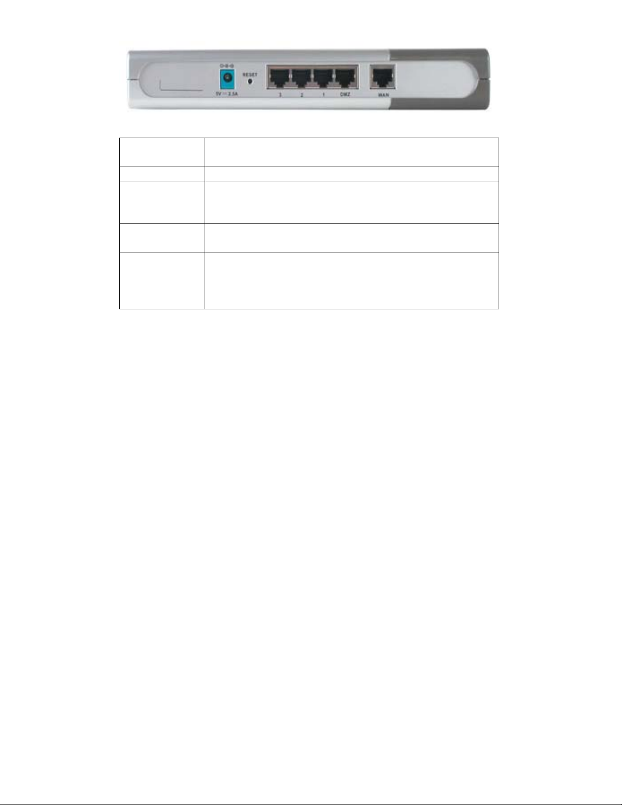
Rearview
Power (5V
Connects the DC power adapter to the Power port
2.5A DC)
WAN Connects DSL/Cable modem to the WAN Ethernet port
Ports 1-3 Connect networked devices such as computers and ftp
servers to the three LAN ports. All LAN ports support
auto crossover.
DMZ Connects a networked device to the DMZ zone of the
Firewall/VPN Router. The DMZ feature can be disabled.
Reset To reload the factory default settings, press the reset
button. Pressing the Reset button will clear the current
configuration as reset the DFL-600 to the factory default
settings.
Product Features
VPN
Provides Virtual Private Networking when communicating with a VPN serverequipped office, or with another DFL-600-equipped network. Supports IPSEC,
PPTP, L2TP, and VPN pass through.
DSL/Cable Modem support
The DFL-600 can connect any Cable or DSL modem to the network.
DHCP
The DFL-600 is a DHCP-capable router. It automatically assigns unique IP
Addresses to each network users that is connected to the DFL-600, for the price of
one Internet account.
Page 7

Firewall Protection
Supports general hacker attack pattern monitoring and logging.
PPPoE Client
Supports PPPoE client function to connect to a remote PPPoE server.
Virtual Server
Allows the internal server to be accessible from the Internet
Upgradeable New Features
Allows new features to be added in the future
High Performance 64 bit RISC CPU Engine
With the most advanced 64 bit RISC CPU Engine, DFL-600 guarantees full
compatibility with future DSL/Cable technologies.
IPSec Security
(DES, 3DES, MD5, SHA-1)
Idle Timer
Set a specified idle-time before automatically disconnecting
Dial-on Demand
Eliminates the need for Dial-up. Automatically logs in to your ISP.
Web-Based Configuration
No software installation required. Can be configured through a web browser making
it OS independent.
Page 8

IP Address Settings and Computer Settings
In order to install the DFL-600 you will need to check your computer’s
settings and the values from your ISP.
The information offered by your ISP:
• Dynamic IP settings
• Your fixed IP address for the gateway
• Your subnet mask for the gateway
• Your default gateway IP address
• Your DNS IP address
If you would like to use PPPoE, you will need the following values from your
ISP in order to install your router:
• User Name
• Password
The static IP settings for the PC:
• Your PC’s fixed IP address
• Your PC’s subnet mask
• Your PC’s default gateway
• Your PC’s primary DNS IP address
Note: The router’s default IP address setting is 192.168.0.1, with a subnet
mask of 255.255.255.0.
Dynamic IP Settings:
It is recommended that you allow your PC’s IP settings be automatically assigned by
a DHCP server. By default, your new DFL-600 VPN Firewall functions as a DHCP
server, and it will give your PC the necessary IP settings, every time you boot your
PC.
Page 9

Introduction and Overview
The DFL-600 Firewall/VPN Router creates two separate networks on the
LAN side of your network − by default, a 192.168.0.0 subnet and a
192.168.1.0 subnet (both with a subnet mask of 255.255.255.0). The DFL600 routes packets between these two subnets and the Internet (or the
network connected to the DFL-600’s WAN port). An Internet Service
Provider (ISP) or a network administrator provides the network address
information on the WAN network.
The 192.168.0.0 network
Area Network on the front panel, and 1, 2, and 3 on the rear panel − are, by
default, assigned the IP address range between 192.168.0.2 to 192.168.0.254.
So computers and other devices connected to these three ports either allow
the DFL-600’s DHCP server to assign them IP addresses from this range, or
you can manually assign devices connected to these ports an IP address from
this range. Remember that the IP address, 192.168.0.0, is reserved. The
DFL-600 is assigned 192.168.0.1 − on the LAN side − and is configured
from a computer (again, on the LAN side of your network) using a web
browser. To connect to the DFL-600’s web-based management utility, type
the IP address https://192.168.0.1 into the Address field of your web browser.
The https specifies the secure version of http.
The 192.168.1.0 network
and rear panel − is, by default, assigned the IP address range between
192.168.1.2 to 192.168.1.254 − with a subnet mask of 255.255.255.0. So
computers and other devices connected to this port must be assigned IP
addresses from this range. The DHCP server on the DFL-600 only services
the LAN ports, so you must manually assign a computer connected to the
DMZ port an IP address from this range.
You can use this default IP addressing scheme, or you can configure your
own. It is important to note that the three LAN ports and the DMZ port must
be on different subnets (different ranges of IP addresses) and that the
computers that are connected to these ports must have IP addresses in the
appropriate range.
−
LAN. The three Ethernet ports labeled − Local
−
DMZ. The port labeled − DMZ on both the front
Page 10

The DMZ port is used to allow computers and devices connected to this port
to have more direct access to the Internet. This is useful for certain
applications that may conflict with the firewall and Network Address
Translation (NAT) features of the DFL-600. Computers and devices
connected to the DMZ port will not have the level of protection that the LAN
ports can provide, however. It is recommended that computers and devices
connected to the DFL-600’s DMZ port have some type of firewall software
installed and running to provide these devices with at least some level of
protection from unwanted intrusions from the Internet.
The Wide Area Network (WAN) side of the DFL-600 is anything connected
to the WAN port. This is normally an Ethernet connection to a Cable or DSL
modem that, in turn, provides a connection to the Internet. There are three
different methods for your ISP to provide the necessary network address
information to your DFL-600.
It can be useful when configuring your DFL-600 Firewall/VPN Router to
think of the LAN side (all computers or devices connected to the three LAN
ports or the DMZ port) and the WAN side (all computers or devices
connected to the WAN port – the Internet). The WAN side of the router is
connected to some device that ultimately allows a connection to the Internet,
while the LAN side is connected to your computers or other network devices
(such as a switch or hub) that ultimately allows users access to the both the
Internet and any other devices on your LAN (such as a printer or scanner).
The network information (including the IP address) required by the WAN
side of the DFL-600 is either obtained automatically from your ISP (or other
network device on the WAN side) or is entered manually. The DFL-600
allows three methods for this information to be obtained, as follows:
Dynamic − your ISP uses the Dynamic Host Configuration Protocol (DHCP)
to provide the network information. Some ISP’s may require you to enter an
assigned Host Name, as well.
Static IP Address − your ISP assigns you an IP address that never changes.
This is more common in businesses that lease dedicated connections. If your
ISP uses this type of connection, you must manually enter the assigned IP
Page 11

address, subnet mask, default gateway address, and primary and (optional)
secondary DNS addresses. This information will be provided by your ISP.
Point-to-Point Protocol over Ethernet (PPPoE) − this protocol requires the
use of a Username and Password to gain access to the network. In addition,
you can specify a Connect on Demand connection that will connect to the
Internet only when a computer or device on your LAN makes a request, or
when the DFL-600 is rebooted.
If you do not know the appropriate method of obtaining the WAN side
network address information, contact your ISP or network administrator.
The Device IP Settings dialog box allows you to specify the IP address that
computers on your LAN will use to access the DFL-600’s web-based
configuration utility. The default is 192.168.0.1 with a subnet mask of
255.255.255.0. If it becomes necessary to change this IP address, be sure to
use an address that is in the same range (on the same subnet) as the three
LAN ports, or you will not be able to access the DFL-600 from your LAN.
The many other features of the DFL-600 are described in subsequent sections.
Page 12
Using the Configuration Utility
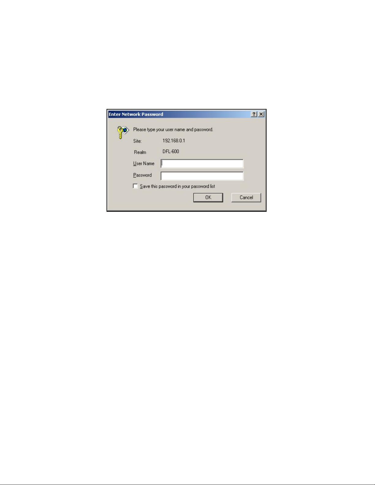
Launch your web browser and type the device IP address (https://
192.168.0.1) in the browser’s address box. This is the default IP address of
your DFL-600. Press Enter.
The following dialog-box will appear to prompt you to enter the DFL-600’s
default User Name and Password. The DFL-600’s default User Name is
admin and the default Password is also admin − all lower case.
Click OK to open the Home menu.
Note: Please make sure that the computer you will use to connect to and
configure the DFL-600 is assigned an IP address that is in the same range as
the DFL-600. The IP address of the DFL-600 is 192.168.0.1. All computers
on your network must be within that range, for instance, the computer IP
address could be any IP address from the range 192.168.0.2 to 192.168.0.254,
with a subnet mask of 255.255.255.0.
Page 13
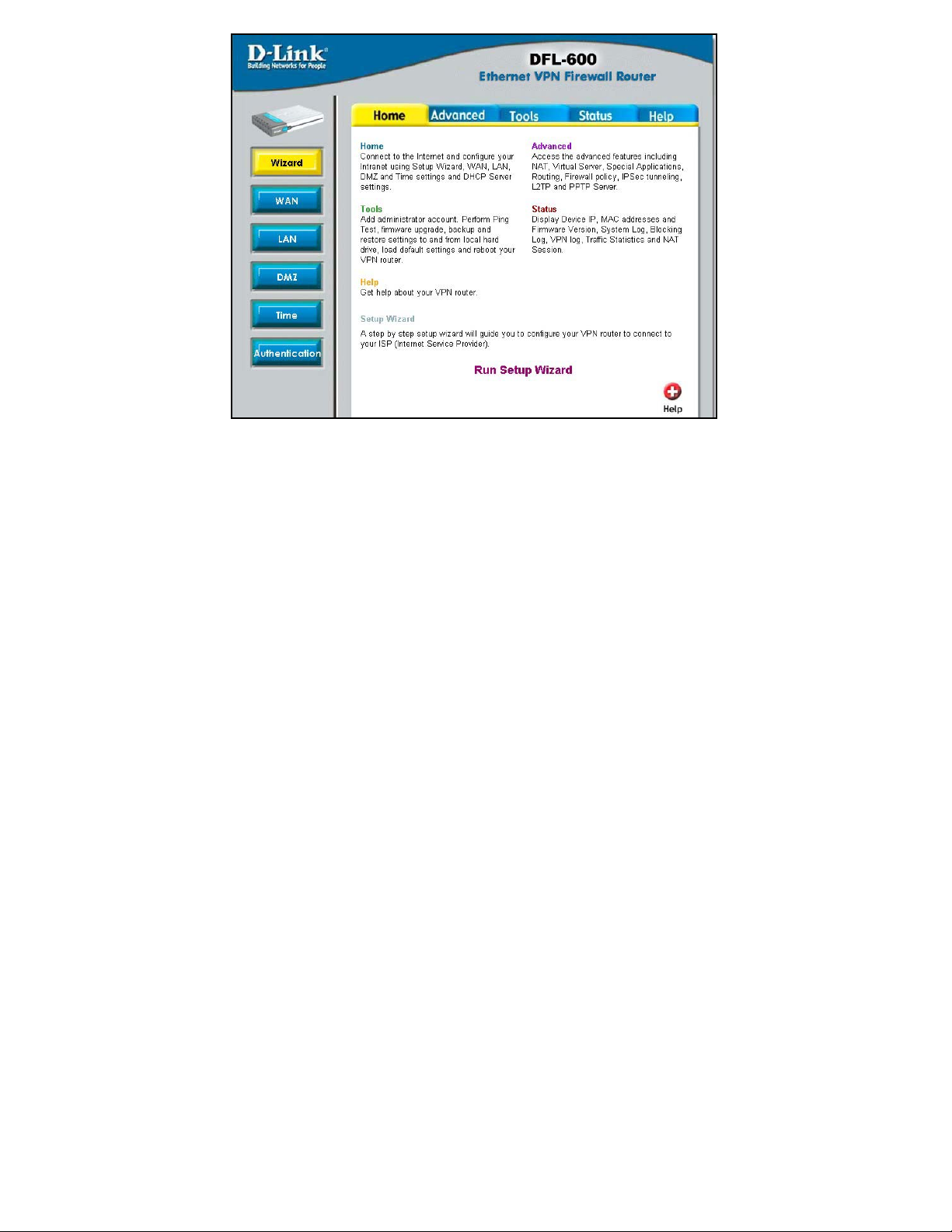
The Setup Wizard will guide you the most basic setup tasks, such as setting
an administrative password, selecting the type of WAN connection you have,
entering your computer’s host name (if required by your ISP), saving the
configuration and restarting the router.
All other setup tasks can be accomplished using the configuration utility from
your web browser.
To use the Setup Wizard, click on the Run Setup Wizard link. This will
start the Setup Wizard.
Page 14
Setup Wizard
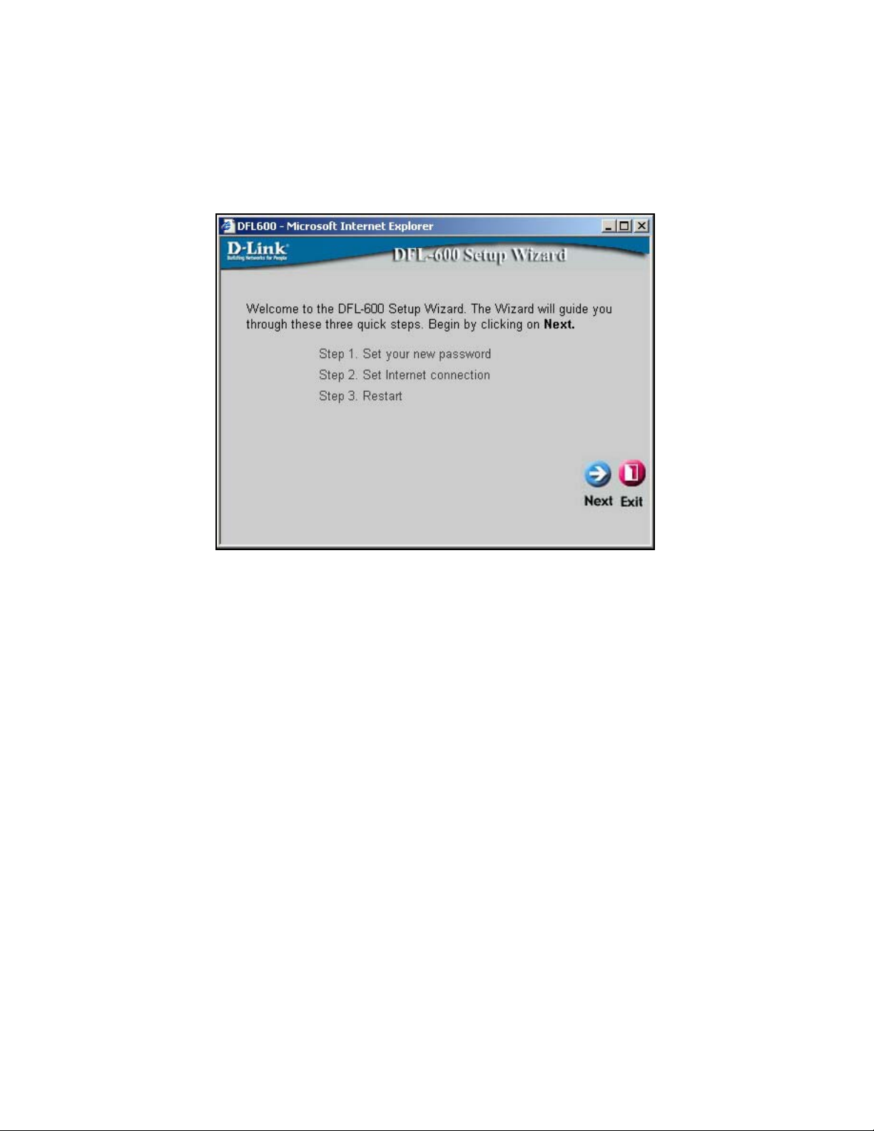
The Setup Wizard will guide you through the most basic setup tasks for the
DFL-600. All other configuration tasks can be accomplished through the
web-based manager.
The Home menu contains a Run Setup Wizard link. Click on this button to
run the Setup Wizard.
Click Next to continue.
Page 15
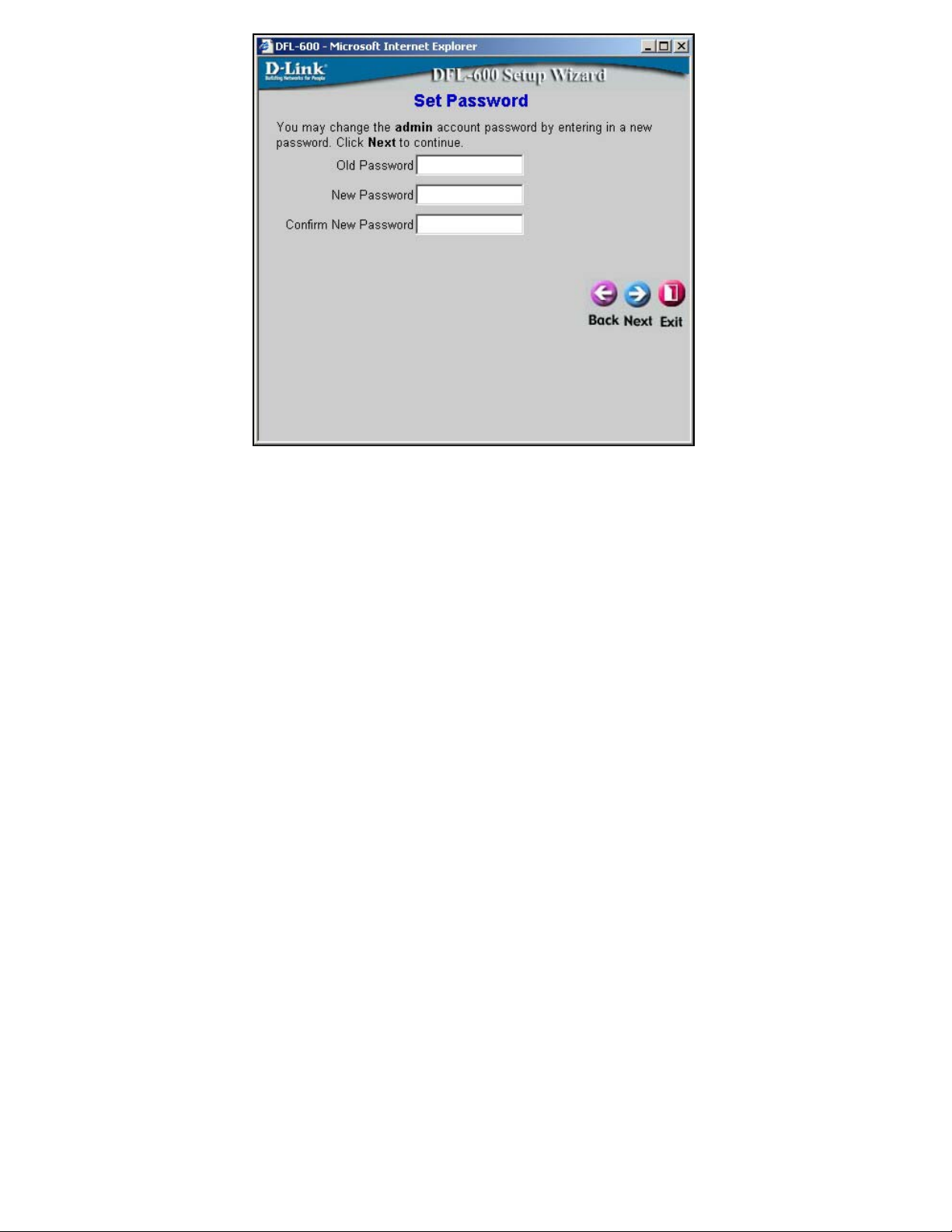
Enter a password in the Password field, and again in the Verify Password
field. This will become the logon password for the DFL-600. This password
is case-sensitive, so remember to use capital letters when logging on to the
DFL-600’s web-based manager − if you enter a password with capital letters
here. The user name, admin, will not be changed here.
Note: If you choose to input a password, please remember it. If you lose your
password, you will have to manually reset the unit (using the reset button on
the rear panel of the unit). Resetting the DFL-600 will return all
configuration parameters to their factory default values, so all of your
settings will be lost and will need to be entered again. The default Username
is admin with a password that is also admin.
Click Next to continue.
Page 16
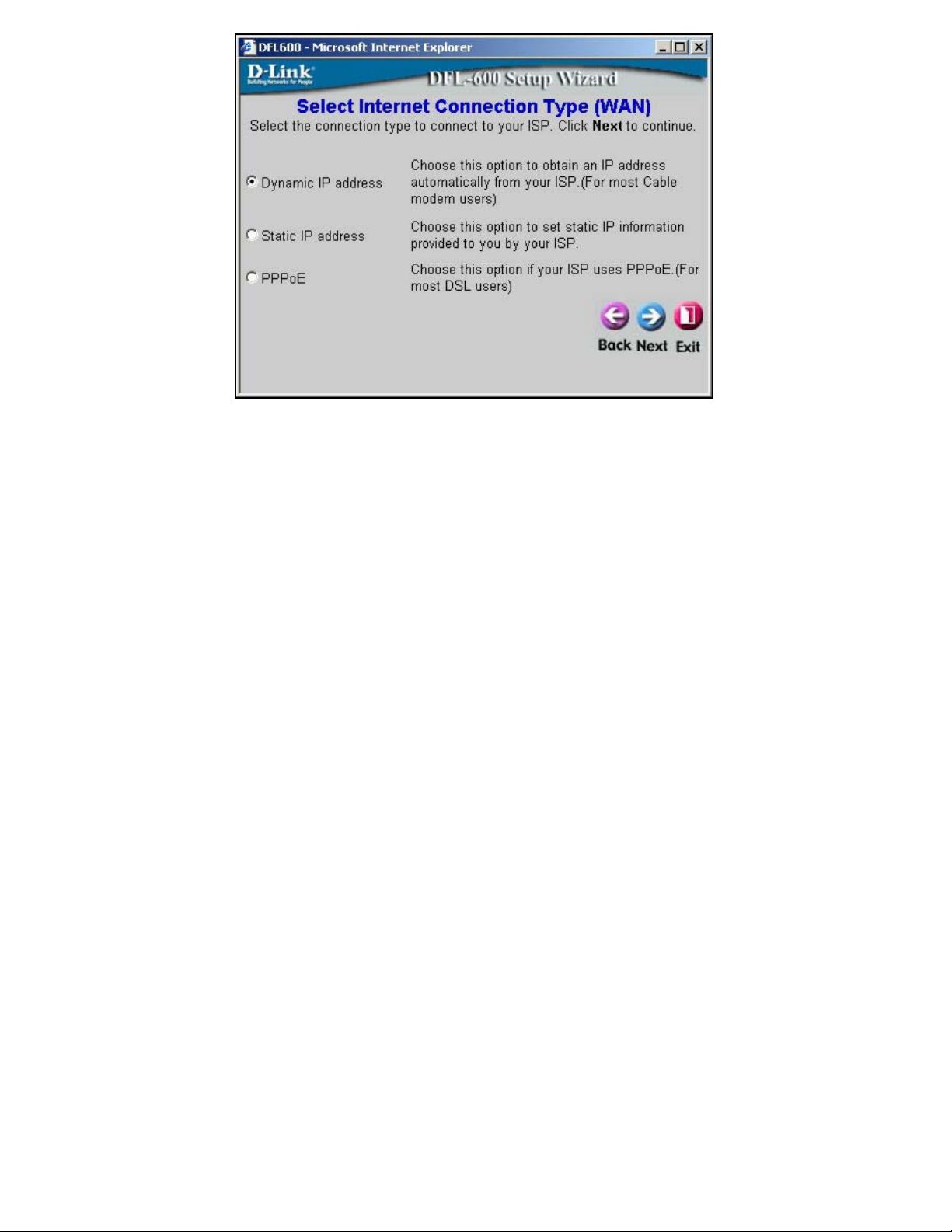
This menu allows you to select the type of connection your ISP provides.
Many ISPs use the PPPoE (Point-to-Point Protocol over Ethernet) for DSL
connections, while many Cable ISPs use DHCP (Dynamic Host
Configuration Protocol). DHCP assigns an IP address for your Internet
connection each time you log on (and is therefore, a dynamic IP address).
DHCP is referred to as Dynamic IP address on the DFL-600. The Setup
Wizard will open a page with the appropriate fields for the entry of your ISP
contact information, depending upon which of the three options you choose.
The Static IP address click-box is used to enter a permanent IP address that
is assigned by your ISP. If your ISP assigns you a permanent IP address,
choose this option.
Click Next to continue.
Page 17

Some ISPs require you to use an assigned host name for your Internet
connection. If your ISP requires this, you can enter the assigned host name in
the Host Name field.
If you selected Static IP Address on the Select Internet Connection Type
(WAN) wizard screen above, the following screen will open:
This screen will allow you to enter the static IP address information, if your
ISP has assigned a static IP address to your Internet account. Your ISP must
provide this information.
If you selected PPPoE (Point-to-Point Protocol over Ethernet) on the Select
Internet Connection Type (WAN) screen above, the following window will
open:
Page 18

This screen will allow you to enter the PPPoE information, if your ISP uses
the PPPoE protocol for your Internet account. Your ISP must provide this
information.
Click Next to continue.
Page 19
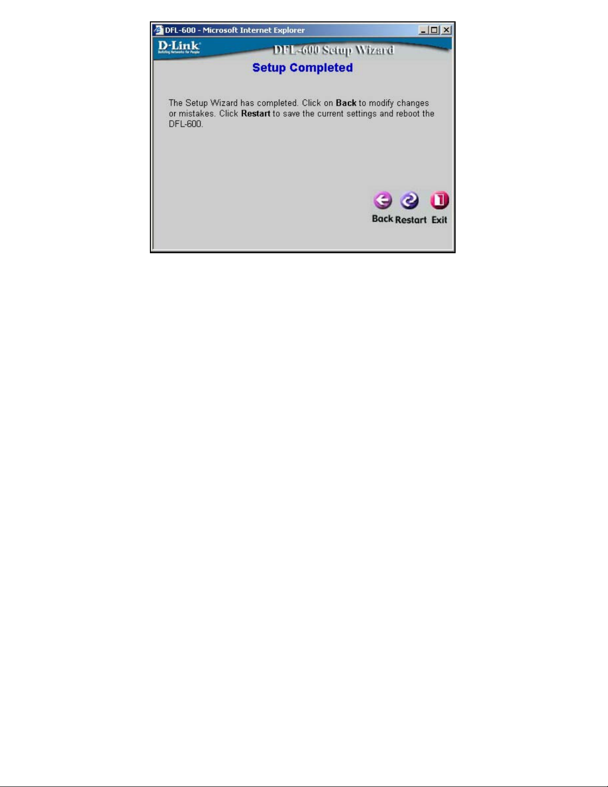
You have completed the basic setup Wizard. The configuration now needs to
be entered into the DFL-600’s non-volatile RAM. Clicking Restart will save
the configuration to non-volatile RAM and restart the router.
Page 20

Home
The Home menu contains links to all of the setup menus for the DFL-600.
Click on the WAN button:
Page 21

WAN Settings
The WAN Settings menu allows you to view the current configuration for
your DFL-600, and to choose the protocol by which your DFL-600 will
receive its WAN network settings.
The settings listed under WAN Settings are the network settings currently in
use by the DFL-600. The fields where you will enter the WAN Settings will
change depending upon the choice you make in the IP Settings Mode dropdown menu. These settings are described below.
Page 22

IP Settings Mode
IP Address
Subnet Mask
This drop-down menu determines how the DFL600 will obtain its IP address information. The
fields where you will enter the information will
change, as appropriate, to reflect the mode you
have selected. The page shown above is in
Dynamic mode.
Dynamic allows the DFL-600 to get its IP
address information from your ISP using the
Dynamic Host Configuration Protocol (DHCP).
Use this setting if your ISP instructs you to use
DHCP or to automatically obtain an IP address.
A server on your ISP’s network will then
automatically send the necessary IP address
information to your DFL-600.
Static allows you to manually enter the
necessary IP address information. Use this
setting if your ISP has permanently assigned an
IP address to your connection.
PPPoE allows you to enter a Username and
Password for a Point-to-Point Protocol over
Ethernet (PPPoE) internet connection. Use this
setting if your ISP has provided you with an
ADSL modem that operates in Bridge mode.
This is the current IP address used to identify
your ‘location’ on the Internet. It is assigned by
your ISP, or entered statically by you. IP
addresses work in combination with a subnet
mask, described below.
A subnet mask is a number, in the same form as
an IP address, that is used to mathematically
separate a range of IP addresses into a Network
portion and a Node portion. The Node portion
identifies a specific device on the Network − in
this case, the DFL-600.
Page 23

Default Gateway
This is the IP address of a device at your ISP’s
office where packets destined for the Internet −
from your home network − are sent, before being
forwarded to their final destination. For the
DFL-600, the Default Gateway address is
provided by your ISP. For computers on your
home network, their Default Gateway is the IP
address of your DFL-600.
Primary DNS Server
This is the IP address of a computer on the
Internet that provides the service of changing
text URLs into IP address for sites on the
Internet. The IP address of this device is
provided by your ISP.
Secondary DNS
Server
This is the IP address of a second DNS server, to
be used in case there is a problem with the
Primary DNS Server. A secondary DNS server
IP address is optional.
The ISP Settings page allows you to modify the way that the DFL-600
obtains its network settings from your Internet Service Provider (ISP). The
entry fields on the page will change depending upon which of the following
options you choose: Dynamic IP Address, Static IP Address, and PPPoE.
Dynamic IP Address − If your ISP uses the Dynamic Host Configuration
Protocol (DHCP) to assign an IP address, subnet mask, default gateway and
Domain Name Server (DNS) addresses, choose this option. Some ISPs
require the use of an assigned Host Name for the device that will make the
WAN connection. You can enter this name into the Host Name field.
This is the type of IP address assignment protocol most commonly used by
cable ISPs. In addition, many cable modems use the MAC address of the
first computer to link to the modem as a way of identifying the user and the
corresponding Internet account. The DFL-600 offers a MAC cloning feature
where the DFL-600 will read the MAC address of the NIC card in the PC that
the cable modem uses to identify the user. The DFL-600 will then use this
Page 24

MAC address when connecting to the cable modem. Clicking on the Clone
button will enable this function.
Remember to click the Apply button and then to save the changes using
Tools, System, and the Save button.
Page 25
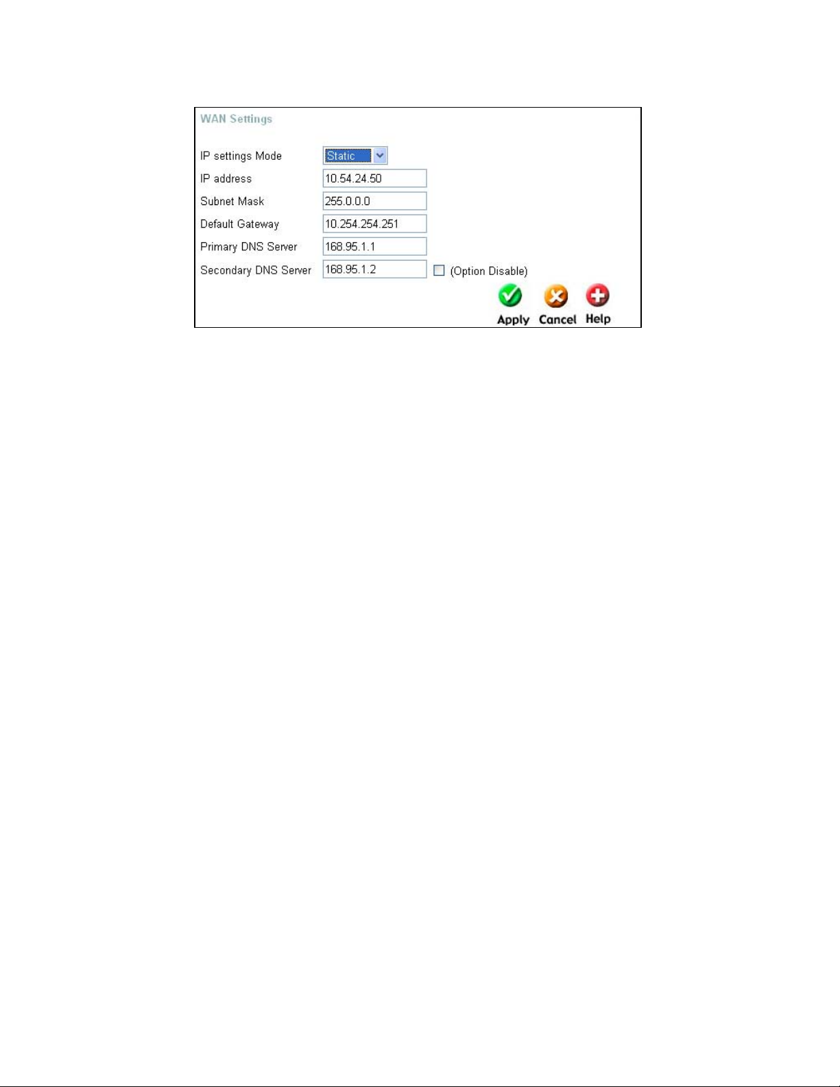
Static IP Address − If your ISP has assigned you an IP address that will
never change, choose this option. When this option is chosen, the following
fields appear to allow you to enter the network address information:
Page 26

PPPoE − If your ISP uses Point-to-Point Protocol over Ethernet (PPPoE),
choose this option. When this option is chosen, the following fields appear to
allow you to enter the network address information:
Connect on Demand − allows the PPPoE WAN connection to be active only
when a computer on your LAN makes a connection request. This is similar
to the way a dial-up modem initiates a connection.
Page 27

LAN Settings
The LAN Settings allows you to view the current IP address and subnet
mask assigned to the DFL-600. It also allows you to change these settings.
If it is necessary to change the IP Address or Subnet Mask assigned to the
DFL-600, enter the new values in the appropriate fields, and press Apply to
make the changes current.
Note: if you assign an IP address and subnet mask to the DFL-600 that is
different from the IP address range assigned to the computers connected to
the LAN ports, you will no longer be able to connect to the DFL-600 from
any of these computers. In order to re-establish the connection between a
computer on the LAN side and the DFL-600, you will need to assign at least
one computer on the LAN side an IP address from the same range as the IP
address you assign to the DFL-600. As an alternative, you can configure the
DFL-600’s DHCP server to give IP addresses from the new IP address range
that you will give the DFL-600 here. If you choose this option, you will have
to reboot the PCs on the LAN side of the DFL-600 in order for them to get
their new IP address settings (or you can enter the “C:\>ipconfig /renew”
command in the Command Prompt window, without rebooting your
computer).
Page 28

As an example, if your LAN network is to be a 192.168.0.x network with a
subnet mask of 255.255.255.0, you might assign the DFL-600 an IP address
of 192.168.0.1 and configure the DFL-600’s DHCP server to assign
addresses in the range between 192.168.0.2 to 192.168.0.100. The default
gateway setting for computers on the LAN side will be the DFL-600’s IP
address − in this case, 192.168.0.1.
Saving all of this information to the DFL-600’s flash RAM and restarting the
router will make this IP addressing scheme current. When you enable DHCP
(in Windows, “obtain an IP address automatically”) and restart the
computers connected to the LAN side of the DFL-600, they will
automatically be assigned IP addresses from the range 192.168.0.2 to
192.168.0.100.
As an alternative, you could disable the DHCP server on the DFL-600 and
manually update the IP address, subnet mask and default gateway
information for each computer on the LAN side of the DFL-600.
It is recommended that if you need to change the IP addressing scheme for
the DFL-600, that you configure the DFL-600’s DHCP server with the
appropriate IP address range and subnet mask first, and then assign an IP
address from the same range to the DFL-600. That way, a computer on the
LAN side of your network can always get the proper network addressing
information by DHCP from the DFL-600 simply by being restarted.
Page 29
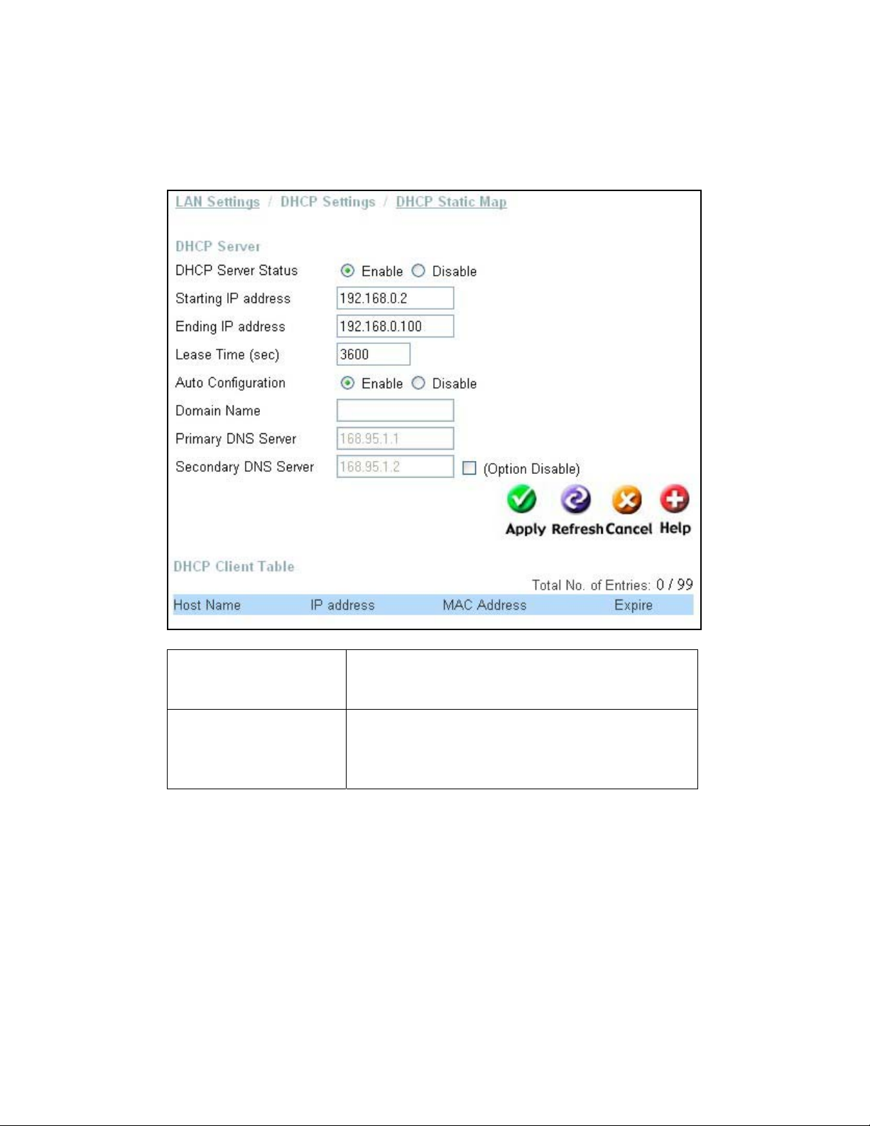
DHCP Settings
g
DHCP (Dynamic Host Configuration Protocol) is a method of automatically
assigning IP addresses, subnet masks, default gateway and DNS server IP
address to computers on the LAN side of the DFL-600. The DFL-600 can be
a DHCP server for your LAN, assigning IP addresses, etc. to computers on
your network from a range of addresses you specify below.
DHCP Server Status
Starting IP Address
This allows you to Enable or Disable the DHCP
Server feature on the DFL-600. The default is
Enabled.
This is the first IP address in a range that the
DFL-600 will assign to a computer on your
network. This IP address can not be the same as
the IP address assi
ned to the DFL-600, nor can
Page 30

Ending IP Address
Lease Time
Auto Configuration
the IP address assigned to the DFL-600 be
contained in the range of IP addresses available
for the DFL-600 to assign. In this case, the IP
address of the DFL-600 is 192.168.0.1, so the
first IP address in the range is 192.168.0.2.
IP addresses can range from 0.0.0.0 to
255.255.255.255, but in the DFL-600’s default
IP addressing scheme, the range is from
192.168.0.0 to 192.168.0.255. Please note that
the addresses ending in 0 and 255 are reserved
for other uses, so the effective IP address range
is 192.168.0.1 to 192.168.0.254. The DFL-600’s
default IP address is 192.168.0.1.
This is the last IP address in a range that the
DFL-600 will assign to a computer on your
network. In this case, the range of IP addresses
between 192.168.0.2 to 192.168.0.100 gives 99
different IP addresses that the DFL-600 can
assign to the computers on your network.
This is the length of time any computer on you
network that is assigned network settings by the
DFL-600 − through the DHCP protocol − can
keep its network settings. If the lease expires
while a computer is logged on to your network,
that computer will request a new set of network
settings. The default is 3600 seconds.
This field allows you to specify whether or not
the DFL-600 will assign the following network
settings to the computers on your network. If
you choose to Enable Auto Configuration, the
following network settings will be obtained
automatically from your ISP by the DFL-600,
and will then be assigned to computers on your
network. If you choose to Disable Auto
Configuration, the network settings you enter in
the fields below will be assigned to computers
on your network.
Page 31

Domain Name
The DFL-600 can provide a domain name to
computers on your network. This domain name
suffix can be provided automatically by your
ISP, or you can enter it statically here. This
suffix will then be automatically added to URL
requests for access to your ISP’s servers.
Primary DNS Server
This is the IP address of a server on the Internet
that provides the service of changing text URLs
into IP address for sites on the Internet. The IP
address of this server is provided by your ISP.
Secondary DNS
Server
This is the IP address of a second DNS server, to
be used in case of a problem with the Primary
DNS Server, above. A secondary DNS server IP
address is optional.
DHCP Static Map
The DFL-600 allows you to identify PCs on your LAN by their MAC
addresses, and then to specify what IP address (from the range of IP
addresses established for your LAN) will be assigned to these PCs. In this
way, you can always have a given PCs on your LAN assigned a given IP
address.
Page 32

MAC Address
IP Address
DHCP Client
This is the MAC address of the PC you want to
assign the IP address specified below using
DHCP.
This is the IP address you want to assign the PC
identified by its MAC address above, using
DHCP.
This identifies the PC as either a DHCP client or
not. This allows you to check to see if the
specified MAC address has already been
assigned an IP address using DHCP.
Page 33

NAT
Network Address Translation
Note: NAT is automatically applied between the WAN and the LAN sides of
the DFL-600. It does not require any user configuration.
Network Address Translation (NAT) is a routing protocol that allows your
network to become a private network that is isolated from, yet connected to
the Internet. It does this by changing the IP address of packets from a global
IP address − assigned by your ISP − usable on the Internet to a local IP
address − assigned by you − usable on your private network (but not on the
Internet.)
NAT has two major benefits. First, NAT allows many users to access the
Internet using a single global IP address. This can greatly reduce the costs
associated with Internet access and helps alleviate the current shortage of
Internet IP addresses. Secondly, the NAT process creates an added degree of
security by hiding your private computers behind one IP address. The NAT
function will normally only allow incoming packets that are generated in
response to a request from a computer on the LAN.
NAT is automatically applied between the IP addresses assigned to the DFL600’s WAN port (the IP address or addresses assigned to you by your ISP)
and the IP addresses assigned to the DFL-600’s LAN ports (the 192.168.0.x
subnet). NAT is not used between the WAN port and the DMZ port.
Complications with Using NAT and Some Applications
NAT is a simple IP address mapping function (that is, it only looks at IP
address headers) and is therefore unaware of the application data embedded
in packets that pass through it.
Page 34

DMZ
NAT and the firewall features of your DFL-600 may conflict with certain
interactive applications such as video conferencing or playing Internet video
games. For these applications, a bypass can be set up using the DMZ port and
a corresponding DMZ IP address. The DMZ IP address is “visible” to the
Internet (or WAN) and does not benefit from the full protection of the NAT
function. Therefore it is advisable that other security precautions be enabled
to protect the DMZ device and other computers and devices on the LAN that
may be exposed. It may be wise to run some sort of firewall software on
these computers and devices.
For example, if you want to use video conferencing and still use NAT, you
can use the DMZ port and DMZ IP address. In this case, you must have a PC
or server through which video conferencing will take place, and that
computer is assigned the DMZ IP address.
By default, the DMZ IP address is 192.168.1.1 with a subnet mask of
255.255.255.0. Note that the DMZ IP address is on a different subnet (the
192.168.1.x subnet) than the LAN ports (by default, the LAN ports are
assigned to the 192.168.0.x subnet).
Page 35

DMZ Settings
The DMZ Settings screen allows you to Enable and Disable the DMZ port
on the DFL-600 and to specify the IP address and Subnet Mask that the DMZ
port will use. The default DMZ IP address is 192.168.1.1 with a subnet mask
of 255.255.255.0.
IP Address
This is the IP address assigned to the
DMZ port, and will be assigned to a PC that you
connect to this port. You can assign any IP
address to the DFL-600’s DMZ port that is
within the range 192.168.1.1 to 192.168.1.254.
Subnet Mask
This is the subnet mask corresponding to the
DMZ IP address specified above. It must be the
same subnet mask as assigned to the LAN ports.
DMZ Host Settings
The DMZ port maps one global IP address − an IP address that is valid on
the Internet, usually assigned by your ISP − to one local IP address from the
IP address range assigned to the DFL-600’s DMZ port.
DMZ Hosts, sometimes referred to as Virtual Servers, are computers on your
LAN that are connected to the DMZ port and are configured to act as servers
Page 36

to connections to the WAN or Internet. The IP address must be from the
same range as the IP address of the DMZ port. The default DMZ IP address
is 192.168.1.1, so DMZ Servers must be from the IP address range from
192.168.1.2 to 192.168.1.254, with a subnet mask of 255.255.255.0.
DMZ host IP address
This is the IP address you have assigned to your
DMZ computer. You will need to manually configure
the IP address settings for each computer you
connect to the DFL-600's DMZ port. It must be from
the same IP address range as you assigned to the
DMZ port. The DFL-600's default IP address range
for the DMZ port is 192.168.1.2 to 192.168.1.254.
Page 37

Time Settings
The DFL-600 can be set to obtain and distribute the correct time to computers
on your LAN using the Simple Network Time Protocol (SNTP). Click on the
Time button to open the following page:
System Date Time
Time Zone
Time Set Type
Displays the current system date and time.
This drop-down menu allows you to select the
time zone in which your DFL-600 is located.
This drop-down menu allows you to specify the
method the DFL-600 will use to obtain the date
and time. Manual allows you to manually enter
the date and time. SNTP allows the DFL-600 to
obtain the date and time automatically from an
SNTP server, as specified below.
Page 38

Set Type
This drop-down menu allows you to select either
the IP address of an SNTP server, or the Domain
Name (URL) of an SNTP server that the DFL600 will contact to obtain the correct date and
time.
IP address
Domain Name
Enter the IP address of an SNTP server here.
Enter the Domain Name (URL) of an SNTP
server here.
YYYY-MM-DD
These fields allow you to manually enter the date
using a year-month-day format.
HH:MM:SS
These fields allow you to manually enter the
time using an hour: minute: second format.
Authentication
The Authentication button opens the User Management page, as shown
below. This page allows you to control how users on your LAN are
authorized and to manage the bandwidth available to users on your LAN.
You can choose from the LDAP, POP3, RADIUS, Local, or 802.1X
authentication protocols. In addition, you can enable or disable the user
authentication without changing the configuration. This is useful when you
are troubleshooting Internet access problems for PCs on your LAN.
Page 39

Clicking the Enable click box, opposite the User Control table entry, will
open the rest of the User Management page, including the Bandwidth control
and Management Type table entries.
Page 40

User Control
Logout Timer
Bandwidth
Management Type
This allows you to enable or disable the
authentication of users on the LAN side of the
DFL-600, without changing the configuration
settings. This is useful when you need to
troubleshoot Internet access problems for PCs on
your LAN.
You can enter a maximum amount of time that
users are allowed to be “logged in”. When a
user is logged in for a period of time longer than
that specified here, they must log in again.
Entering a ‘0’ disables the logout timer.
This allows you to enable or disable the
bandwidth control feature of your DFL-600.
Use the drop-down menu to set the maximum
data rate that the DFL-600 will allow between
PCs on your LAN and the WAN (the Internet).
This allows you to choose and configure the
protocol that the DFL-600 will use to
authenticate users. You can choose between the
LDAP, POP3, RADIUS, Local, or 802.1X
authentication protocols. The Local protocol
means that the DFL-600 itself will provide user
authentication, based on Usernames and
Passwords that are entered by clicking the Add
Users link. You can view the list of users by
clicking the Users List link. The configuration
of the other authentication protocols is described
below.
Page 41

Clicking the Add Users link will open the following page:
Add Users
This allows you to add User names and
Passwords for users on your LAN. In the Local
mode, the DFL-600 authenticates users based
upon the User name and Password entered here.
User name
Password
Enter a User name here. Enter a Password corresponding to the User name entered above.
POP3
The Post Office Protocol, version 3 (POP3) is used to access and retrieve email from a mailbox on a server that is usually located at your ISP’s facility.
Choosing POP3 will allow the DFL-600 to connect PCs on your LAN to the
POP3 e-mail server on the WAN to view and retrieve e-mail.
Clicking the POP3 click box will open the following page:
Page 42

POP3
The Post Office Protocol, version 3. This is used
to view and retrieve e-mail from a POP3 server
on the WAN.
Server IP
Enter the IP address of your POP3 server here.
Your ISP should provide you with this address.
Server Port
This is the TCP port number that the POP3
server will use to communicate with PCs on your
LAN. TCP port 110 is the ‘well known’ or
default port used for the POP3 protocol.
RADIUS
The Remote Access Dial-in User Service (RADIUS) is one of the most
common protocols used to carry authorization, authentication, and
configuration information between a RADIUS server on the WAN and PCs
on your LAN. Choosing RADIUS will allow the DFL-600 to connect PCs on
your LAN to a RADIUS server on the WAN. If RADIUS user authentication
is enabled on the DFL-600, PCs on your LAN will require entering a
Username and Password into the Windows Logon dialog box before they can
access the Internet.
Page 43

If you have some PCs (or other network devices) that do not require RADIUS
user authentication to access the WAN (Internet), you can enable 802.1x, and
then enter the IP Address and IP (subnet) Mask of these devices under the
Edit link (which will appear when you enable 802.1x). PCs and network
devices that have their IP Address and IP (subnet) Mask entered on the
802.1x Device Configuration page will be allowed to access the WAN
(Internet) by the DFL-600 without any RADIUS user authentication,
effectively bypassing the RADIUS user authentication step.
Clicking the RADIUS click box will open the following page:
Page 44

RADIUS
802.1X
Server IP
Authentication Port
Accounting Port
The Remote Access Dial-in User Service
(RADIUS) is one of the most common protocols
used to carry authorization, authentication, and
configuration information between a RADIUS
server on the WAN and PCs on your LAN.
Choosing RADIUS will allow the DFL-600 to
connect PCs on your LAN to a RADIUS server
on the WAN.
802.1x is a standard for passing the Extensible
Authentication Protocol (EAP) packets over a
LAN. You should enable this if there are any
802.1x devices between the DFL-600 and the
RADIUS server on the WAN. Clicking on the
Edit link (which appears when you enable
802.1x) will open the 802.1x Device
Configuration page, as shown below.
If you have PCs on your LAN that do not require
RADIUS user authentication to access the
Internet (or other networks through your ISP),
you can use Enable 802.1x, and then click the
Edit link. This will allow you to enter the IP
Address and IP (subnet) Mask of PCs on your
LAN that need to bypass the RADIUS user
authentication. PCs (and network devices)
whose IP Addresses and IP (subnet) Masks are
entered on the 802.1x Device Configuration
page will be allowed to access the Internet
without RADIUS user authentication.
Enter the IP address of the RADIUS server on
the WAN that you will use to authenticate users
on your LAN. Your ISP should provide you
with this address.
Enter the TCP/UDP port number that the
RADIUS server will use to connect to PCs on
your LAN. The default port number for
authentication is 1812.
Enter the TCP/UDP port number that the
Page 45

RADIUS server will use to connect to PCs on
your LAN for the RADIUS accounting function.
The default port number for accounting is 1813.
Secret Key
Enter the shared key used between PCs on your
LAN and the RADIUS server.
Accounting Service
Use the drop-down menu to enable or disable the
RADIUS accounting service.
Authentication Method
Use the drop-down menu to enable or disable the
RADIUS accounting service.
Clicking the 802.1x Enable click-box, and then Edit link will open the
following page:
802.1x is a standard for passing the Extensible Authentication Protocol
(EAP) packets over a LAN. You should enable this if there are any 802.1x
devices between the DFL-600 and the RADIUS server on the WAN.
Page 46

Clicking on the Edit link (which appears when you enable 802.1x) will open
the 802.1x Device Configuration page, as shown below.
If you have PCs on your LAN that do not require RADIUS user
authentication to access the Internet (or other networks through your ISP),
you can use Enable 802.1x, and then click the Edit link. This will allow you
to enter the IP Address and IP (subnet) Mask of PCs on your LAN that need
to bypass the RADIUS user authentication. PCs (and network devices)
whose IP Addresses and IP (subnet) Masks are entered on the 802.1x Device
Configuration page will be allowed to access the Internet without RADIUS
user authentication
Page 47

802.1X
IP (Segment) Address
IP (Segment) Mask
802.1x is a standard for passing the Extensible
Authentication Protocol (EAP) over a LAN.
You should enable this only if there are 802.1x
devices between the DFL-600 and the RADIUS
server on the WAN. Clicking on the Edit link
(which appears when you enable 802.1x) will
open the 802.1x Device Configuration page, as
shown below. Use this table to enter the IP
Address and IP Mask
The DFL-600 supports only 802.1X pass
through. This means that the DFL-600 will
forward 802.1X packets from a RADIUS server
on the WAN (Internet) to PCs on your LAN. If
you enable 802.1X and do not enter the IP
Address and IP Mask of a PC on your LAN in
the 802.1x Device Configuration menu, that PC
will not be allowed to access the Internet without
being authorized by a RADIUS server.
PCs on your LAN that have their IP Address and
IP Mask entered into the 802.1x Device
Configuration table, will be allowed to access
the Internet without being authorized by a
RADIUS server.
Enter the IP address of an 802.1x device
between the DFL-600 and the RADIUS server
on the WAN.
Enter the subnet mask corresponding to the
802.1x device’s IP address you entered above.
LDAP
LDAP (Lightweight Directory Access Protocol) serves as an Internet
phonebook. When you are using e-mail programs, LDAP lets you lookup
people's names and find their e-mail addresses, phone numbers, and office
location. Of course, this assumes that you work inside a company or
university where the net administrators have setup such a server for your use.
Page 48

Clicking the LDAP click box will open the following page:
LDAP
Server IP
Enter the IP address of your LDAP server here.
Your ISP should provide you with this address.
Server Port
This is the TCP port number that the LDAP
server will use to communicate with PCs on your
LAN. Port 389 is the ‘well known’ or default
port used for LDAP, while Secure LDAP uses
port 636.
Base DN
This is the Distinguished Name used for LDAP.
Page 49

Advanced Settings
NAT
Network Address Translation
Network Address Translation (NAT) is a routing protocol that allows your
network to become a private network that is isolated from, yet connected to
the Internet. It does this by changing the IP address of packets from a global
IP address − assigned by your ISP − usable on the Internet to a local IP
address − assigned by you − usable on your private network (but not on the
Internet.)
Virtual Servers
Virtual Servers allow remote users to access services on your LAN such as
FTP for file transfers or SMTP and POP3 for e-mail. The DFL-600 will
accept remote requests for these services at a Global IP Address you specify,
using the specified TCP or UDP protocol and port number, and then redirect
these requests to the server on your LAN with the Private IP address you
specify.
Page 50

Private IP
Transport Type
This is the IP address of the server on your LAN
that will provide the service to remote users.
You can select the transport protocol (TCP or
UDP) that the application on the virtual server
will use for its connections. The choice of this
protocol is dependent on the application that is
providing the service. If you do not know which
protocol to choose, check your application’s
documentation.
Page 51

Application Gateway (ALG)
gg
Some applications (programs running on a PC on your LAN) require multiple
TCP or UDP ports to function properly. Applications such as Internet
gaming, video conferencing, and Internet telephony are some examples of
applications that often require multiple connections. These applications often
conflict with NAT, and therefore require special handling. The Special
Applications page allows you to configure your DFL-600 to allow computers
on your LAN to access servers on the WAN that require multiple TCP or
UDP connections.
Application Name
Trigger Port Range
This is a reference − usually the name of the
application. In the above example, Netmeeting
is the application, and this is used to name this
entry.
This is the TCP or UDP port range used to
tri
er, or start, the application. It can be a
Page 52

Trigger Type
p
Max Activity Interval
Session Chained
Address Replacement
Replacement Format
Allow sessions
initiated from/to 3rd
host
Popular Applications
single port, or a range of ports. If only a single
port is used, enter the same port number in both
the starting and ending port number fields.
This is the protocol (TCP or UDP) that the
application uses to make the connection.
This is the maximum interval, in milliseconds,
between the triggering of a protocol session and
the protocol’s dynamic session.
If the application allows a dynamic session
(connections) to trigger a new session, set this to
Enabled. If an application uses protocols in
addition to the TCP/UDP protocols (like many
interactive Internet games), then this application
will likely create additional sessions (using these
additional protocols) that will need to associate
with the first session. Again, Session Chained
should be set to Enabled, for this type of
application,
This option is used in Network Address
Translation (NAT) to translate a binary IP
address in a TCP/UDP packet. When a TCP or
UDP packet is received by the DFL-600, the IP
address in this packet will be translated between
the WAN and LAN side of the DFL-600, if this
option is enabled.
This drop-down menu allows you to specify
either the TCP or UDP protocol for the Address
Replacement function above.
Click this check box if your application allows a
new session to be started with a different
computer than the one that started the first
session. For example, MSN file transfer requires
a connection with a remote host, but this
connection is not direct. There are other MSN
servers between your PC and the MSN file
server.
The settings for a range of popular applications
have been
re-entered into the DFL-600’s
Page 53

firmware and can be selected here from the dropdown menu. Selecting one of the listed
applications is the equivalent of entering the
correct settings in the fields above for the
specific application. For example, the
Netmeeting application requires a Trigger Port
Range of 1720 – 1720, a Trigger Type of TCP,
and so on. The correct settings for the
applications listed in this drop-down menu have
been entered into the DFL-600’s firmware, for
your convenience.
Static Routing
Your DFL-600 can automatically discover routes to destinations on both your
LAN and the WAN (Internet). In addition, you can add entries to the DFL600’s routing table that will be saved to flash RAM. These routes will not
age out, and are therefore static.
Page 54

Destination IP
Network
Subnet Mask
Gateway IP Address
Dynamic Routing
Your DFL-600 can automatically discover routes to destinations on both your
LAN and the WAN (Internet). You can choose either RIP1, RIP2 or None.
RIP2 (Routing Information Protocol version 2) adds support for variablelength subnet masks, and is generally the best choice. Choosing None will
disable the routing function of your router, as will choosing Disabled for the
WAN or LAN RIP interface.
This is the IP address of the remote network that
the DFL-600 will route service requests to.
This is the corresponding subnet mask for the
remote network.
This is the IP address of the gateway on the
remote network that will provide the connection
between your DFL-600 and servers on the
remote network.
Page 55

g
Rip Version
RIP Enabled
Interface
Your DFL-600 can automatically discover routes
to destinations on both your LAN and the WAN
(Internet). You can choose either RIP1, RIP2 or
None. RIP2 (Routing Information Protocol
version 2) adds support for variable-length
subnet masks, and is generally the best choice.
Choosing None will disable the routing function
of your router, as will choosing Disabled for the
WAN or LAN RIP interface.
These two click boxes allow you to enable or
disable RIP for either the LAN or WAN
interface. Choosin
Disabled for the WAN or
Page 56

Network Address
Subnet Mask
Interface Name
Multicast Support
Update Timer
Timeout Timer
Garbage Collection
Timer
LAN RIP interface will disable the routing
function of your router.
This is the IP address of either the LAN or WAN
side of your DFL-600.
This is the subnet mask corresponding to the
Network Address above.
This is the name of the interface corresponding
to the Network Address above.
You can enable or disable multicast support. It
is recommended that you enable this feature.
This allows you to specify how often the DFL600 will update its routing table. The default is
30 seconds.
This allows you to specify how long a route
discovered by the DFL-600 will remain in its
memory without being used. The default is 180
seconds.
This allows you to specify the period of time
between the collection of garbage routes. The
default is 120 seconds.
Routing Information
Your DFL-600 can automatically discover routes to destinations on both your
LAN and the WAN (Internet), and you can also enter routing information
statically. To display the Routing Information table, click on the Routing
Information link. This information is displayed in the Routing Information
table, as shown below.
Page 57

In the case shown above, the DFL-600’s WAN port was connected to a
10.0.0.0 network − with a subnet mask of 255.0.0.0. The LAN ports used the
default 192.168.0.0 network addresses, and the DMZ port used the default
192.168.1.0 network addresses − both with a subnet mask of 255.255.255.0.
The 0.0.0.0 IP address signifies the Broadcast address − the address within
the DFL-600 where all packets that have an unknown destination address are
forwarded. The DFL-600 then relates the 0.0.0.0 IP address to the WAN’s
gateway address of 10.254.254.251. This route is labeled as the Default
route, and leads to the Internet.
Page 58

Policy (Firewall) Configuration
Some Examples
Your DFL-600 allows you to make policy rules and then group these rules
into a policy that will limit the types of access PCs on your LAN can have to
the WAN (Internet). In addition, you can create a Schedule that will
determine at what times and days of the week these policies are enforced.
Finally, the DFL-600 offers a Global Policy Status page that allows you to
enable or disable the filters that control what type of access to the WAN
(Internet) PCs on your LAN can have, and what type of access to Virtual
Servers and Application (ALGs) on your LAN can be granted to PCs on the
WAN (Internet).
The DFL-600 offers many preset options for making these policies, and
rather than describing them individually, a series of examples may be most
informative.
Example 1 − Limiting Web-page Access
In this example, you will deny any PC on your LAN from accessing webpages on the WAN (Internet) between the hours of 6 pm and 9 pm, Monday
through Friday.
Setting the Schedule
Let’s say that you are concerned that your children will access web-pages on
the Internet when they should be studying or doing their homework. In this
case, the schedule would be established first. To do this, click on the
Schedule button to open the Schedule Rules page, as shown below.
Page 59

A schedule called NoWeekDays has been entered with the hours between 6
pm and 9 pm checked for the weekdays Monday through Friday. Click on
the Apply button to enter this schedule into the Schedule Table.
You can enter up to 15 Schedules, but two default schedules are
automatically maintained by the DFL-600 − Always and None. You can
make changes to the None Schedule, but the Always Schedule is intended for
policies that should always be enforced.
To check the entered schedules, click the Schedule Table link. This will
open the Schedule Table, as shown below.
Page 60

You can change the times and days entered for a Schedule by clicking on the
link below the Schedule View heading. This will open the Schedule Rules
page for the corresponding Schedule Name, and allow you to make changes.
Setting the Policy Rules
Now you need to configure the DFL-600 to block PCs on your LAN from
accessing Web-pages on the WAN (Internet). To do this, click on the Policy
button to open the Policy Rules page, as shown below.
Enter a name for this rule in the Rule Name field. This name is used to
reference the Policy Rule. For this example, we will use BlockWeb for the
policy rule name.
In order to block PCs on your LAN from downloading web-pages from the
WAN (Internet), you need to select the HTTP (Hyper Text Transfer Protocol)
from the Protocol drop-down menu. HTTP is the protocol that the World
Wide Web uses to transfer web pages from the Internet to a PC on your LAN.
The HTTP protocol uses TCP port 80 to make connections to PCs, but the
necessary parameters for a Policy Rule are already entered when you select
http(80) from the Protocol drop-down menu.
Most of the commonly used protocols on the Internet are already entered in
the Protocol drop-down menu.
Next you need to specify the IP addresses of the possible sources of PCs on
your LAN that this Policy Rule will apply to. You can specify any IP address
range that may include all of the PCs on your LAN, or limit the IP address
Page 61

range to PCs that you want the Policy Rule to apply to, and leave PCs with IP
addresses outside the range free to access web-pages on the WAN (Internet).
For simplicity in this example, we are going to specify Any in both the
Source IP Range and Destination IP Range fields. This will mean that any
PC on your LAN will be denied access to web-pages on the WAN (Internet)
regardless of that PC’s IP address.
Adding the Policy Rule to a Policy Group
After clicking the Apply button to add the BlockWeb Policy Rule to the
Service Rules table, the page appears as shown below.
Page 62

Now that the Policy Rule − Block Web − is configured, we want to add this
Policy Rule to a Policy group. Click on the Policies link to open the Policy
Add page, as shown below.
Page 63

Enter a name for the Policy group in the Policy Name field. This name will
be used to reference this Policy group. In this case, we have named this
Policy group StudyTime. The schedule we created previously will appear in
the Assign to Schedule drop-down menu and is selected as the times and
days of the weed this Policy will be enforced. We want to deny access to
PCs on our LAN, so in the Action drop-down menu, we select Deny.
Clicking the Apply button will enter the Policy into the Policy group table, as
shown above. Clicking on the icon under the Edit heading will open the
following page.
Page 64

Under the Rule Filter heading, click Enabled, and then click the
“Outbound Firewall Rule” link. This will open a page that contains all of
the Policy Rules that apply to Outbound packets, as shown below.
Page 65

Click the box under the Add heading to add the BlockWeb Policy Rule to
the StudyTime Policy group. Click the Apply button to make the entry
current.
Click the Back button to return to the Policy Add page.
Setting the Policy Global Status
Now we need to configure the Global Policy Status. Click the Global
Policy Status link − from the Policy Add page − to open the following page.
Page 66

For the BlockWeb Policy Rule and the StudyTime Policy group, we need to
set the Outbound Port Filter to Enabled − by clicking the Enabled clickbox − and to select the Allow all except policy settings option. When Allow
all except policy settings is selected, the DFL-600 will drop (filter) packets
that meet the criteria established in the Policy Rules (in this case, HTTP
packets). All other packets will be forwarded to their destination. If we had
selected Deny all except policy settings, then the DFL-600 would forward
only HTTP packets. All other packet types would be dropped (filtered).
This Policy configuration will block HTTP packets (using TCP port 80 − the
default port number for the HTTP protocol) from being sent from PCs on
your LAN to the WAN (Internet) between the hours of 6 pm and 9 pm and
the weeddays Monday through Friday. This will effectively block access to
the Internet from PCs on your LAN during these times.
Page 67

Remember to save the Policy configuration into the DFL-600’s non-volatile
RAM using the Save button (under the Tools tab, click the System button to
see the Save options). This will ensure that the DFL-600 will retain the
Policy configurations when it is restarted or if the AC power is interupted.
Example 2 − Limiting Access to Internet Domains
Policy Rules
The DFL-600 allows you to specify rules that it will use to limit access (filter
packets) to and from PCs on your LAN. A policy rule on the DFL-600
establishes what information packets must contain before an action is taken
by the router. The action taken when a packet is read by the DFL-600 is
specified on the subsequent web pages, described below. To configure a
policy rule, click on the Policy button to open the Policy Rules page, as
shown below.
Page 68

Enter a name for the policy rule you want to configure in the Rule Name
field. This name will appear in the Service Rules table, along with all of the
parameters you specify for the rule, and is used to identify and reference the
rule on subsequent web pages, as described below.
In the case shown above, a rule called notelnet has been entered to block
telnet packets from coming in from the WAN to the LAN. The rule was
constructed using the Protocol drop-down menu, and then selecting the
telnet(23) entry to specify the TELNET protocol, TCP transport type, and
TCP port number 23. Most of the commonly used protocols on the Internet
are listed in the Protocol drop-down menu. Their transport types and port
numbers are automatically entered, when you select one of these protocols.
If you need to configure a policy rule for a protocol that is not listed, you can
manually enter the Transport Type, and Port Range in the appropriate
fields. For this type of policy rule, the Protocol is listed as –user defined-.
Page 69

The next step is to specify if you want the policy rule to apply to Inbound or
Outbound packets. Inbound here means from the WAN to your LAN, while
Outbound means from your LAN to the WAN. The Direction drop-down
menu allows you to choose which direction the DFL-600 will filter packets
that meet the criteria of the policy rule.
Please Note: at the time of the writing of this manual, the Inbound direction
specification for Policy Rules only applies to the Application (ALGs) and
Virtual Servers that have been set up on the NAT page.
If, for example, you want to prevent the TELNET protocol from being used
to access PCs on your LAN from the Internet (WAN), your would specify
Inbound. If you want to prevent PCs on your LAN from using TELNET to
access PCs on the Internet (WAN), you would specify Outbound. Entering
two policy rules for inbound and outbound packets will totally eliminate a
given protocol from being used to across the DFL-600.
You can specify a range of TCP or UDP ports using the Port Range field.
Selecting Any will prevent any port from being used.
In addition, you can specify a range of IP addresses − as either a source or a
destination − that the policy rule will be applied to.
Once you have configured the policy rule and clicked on the Apply button,
the rule will be entered into the Service Rules table. If you need to change
the policy rule, click on the icon in the View field of the Service Rules table.
This will allow you to view and modify the rule’s configuration. To delete a
policy rule, click on the icon in the Del field.
Global Policy Status
Once you have configured the Policy Rules, you need to determine how the
DFL-600 will apply these rules to the packets that cross between your LAN
and the Internet (WAN). The Global Policy Status page enables you to
specify this.
“Default” on this page means “if no packets that meet the criteria established
in the policy rules, then ...” either “allow all” or “deny all”. On the Global
Page 70

Policy Status page, “Default allow all” means that the DFL-600 will allow
all packets except those that meet the criteria established in the policy rules.
“Default deny all” means that the DFL-600 will deny (filter) all packets
except those that meet the criteria established in the policy rules.
Policies − Policy Add
Once you have defined what type of packets you want the DFL-600 to look
for, you need to assign those rules to a policy. Clicking on the Policies link
will open the Policy Add page, as shown below.
Page 71

Enter a name for the new group of policy rules in the Policy Name field.
This name is used to reference the group of policy rules. You can also assign
this group of policy rules to a schedule (which is either Always or a schedule
you can create below). Finally, you can choose to Allow or Deny access.
Blocking Internet Domains
The DFL-600 will allow you to make a list of Domain names for which
packets will be filtered.
Clicking on the Domain Add link on the Policy Rules page will open the
following page.
Page 72

Enter a domain name you want to limit access to in the Domain Name field.
Click the Apply button to add this domain name to the list.
Blocking Keywords
The DFL-600 will allow you to make a list of keywords for which packets
will be filtered
Clicking on the Keywords Add link on the Policy Rules page will open the
following page.
Enter a key word you want the DFL-600 to examine packets for in the Key
Word field. Click the Apply button to enter this key word into the list.
Page 73

Blocking MAC Addresses
The DFL-600 will allow you to make a list of MAC addresses for which
packets will be filtered. MAC (Media Access Control) addresses are the
physical addresses that are assigned to networking devices by their respective
manufacturers. These addresses are 12 hexadecimal digits long and are in the
form 01-23-45-67-89-AB − where the numerals 0-9 and the letters A-F are
used.
Clicking on the MAC Add link on the Policy Rules page will open the
following page.
Enter a MAC Address that you want the DFL-600 to scan for and filter
packets that have that MAC address as their destination address. Click the
Apply button to enter the MAC address into the table.
Page 74

IPSec Settings
IPSec (IP Secure) is a group of IP extensions developed by the Internet
Engineering Task Force (IETF) to provide security services that are
compatible with the existing IP standard. IPSec provides authentication,
integrity, access control, and confidentially. The data and information
exchanged between two ends of an IPSec connection can be encrypted and
verified. Virtual Private Network (VPN) Tunnels can be created to allow
encrypted and secured communication across networks or the Internet.
The two protocols provided by IPSec are Authentication Header (AH) and
Encapsulated Security Payload (ESP).
The AH (Authentication Header) addresses data origin authentication, data
integrity, and replay protection. The ESP (Encapsulating Security Payload)
header addresses the same features and also includes data confidentiality or
encryption capabilities. By default, IPSec uses the AH as a minimum
security level. If data confidentiality is desired, the AH is replaced with an
ESP header for the encryption feature and the authentication and data
integrity components that the AH offer as well.
The DFL-600 can be configured to either establish and maintain an IPSec
connection with a remote workstation, or to simply allow the IPSec packets
to pass through it. The IPSec Passthrough mode allows the IPSec packets to
be forwarded to a PC on the LAN side of the DFL-600. This PC should then
have the appropriate software running on it to establish and maintain the
IPSec connection.
To enable IPSec Passthrough, click on the VPN-IPSec button to open the
IPSec Settings page, as shown below.
Page 75

IPSec Pass-through
Click Enable to allow IPSec packets to pass
through the router to the destination computer on
your LAN. When IPSec Pass-through is
enabled, the DFL-600 will allow IPSec packets
to reach their destination computer on your
LAN.
IPSec Status
Click Enable to make the IPSec settings active.
Manual Key Settings
There are two methods for exchanging the encryption/decryption keys
required by IPSec − Manual Key entry and Internet Key Exchange (IKE).
The difference between Manual Key and IKE is how the encryption keys and
SPI are determined. For a Manual Key VPN, the encryption key,
authentication key (if required) and SPIs are predetermined by a Network
Administrator when configuring the connection.
The differences between Manual Key and IKE can be summarized as:
• a al Ke on key
M nu y VPN requires the encryption key, authenticati
(if
required), and SPIs to be predetermined by a network
adm
inistrator when the IPSec connection is configured.
• For an IKE VPN, the keys and SPIs are negotiated between VPN
gateways. The two VPN gateways can then use these keys and
Page 76

SPI
s to maintain the IPSec connection.
An IKE VPN i VPN
s generally considered more secure than a Manual Key
because IKE can generate new keys and SPIs randomly during the
negotiation phase.
T
o configure a Manual Key VPN, click the Manual Key link to open the
page shown below.
Page 77

Add/New Tunnel
Tunnel ID
Termination IP
Shared Key
Local SPI
Remote SPI
IPSec Operation
The following fields will identify the Manual
Key VPN tunnel on the DFL-600.
An alphanumeric string that identifies the
remote tunnel. A sting of up to 63 characters
can be entered. The Tunnel ID is som
etimes
called the Negotiation ID of the remote
gateway
.
The IP address of the remote gateway.
The encryption key that should be entered
exactly the same way on both endpoints in
order to establish Phase 1 negotiation.
Refers to the SPI of your DFL-600 when
establishing a VPN tunnel.
Refers to the SPI of the remo
which the VPN tunnel will be
This drop-down menu a
kind of encryption that will be app
packets that are sent between the tw
te peer toward
established.
llows you to select the
lied to
o endpoints
of a VPN tunnel.
ESP − specifies that the en
encrypted (by the DES or 3DES algorithm
tire packet will be
, as
selected below) and authenticated (by the MD5
or SHA algorithm, as selected below).
AH − specifies that only the auth
entication
algorithm (MD5 or SHA, as selected below)
will be used. When AH is selec
ted, the data
portion of packets sent between the two
endpoints of a VPN tunnel will not be
encrypted.
Page 78

ESP Transform
Encryption Key
(ASCII)
ESP Auth
ESP Auth Key
(ASCII)
This drop-down menu allows you to select t
encryption algorithm that will be used w
ESP is selected in the IPSec Operation d
he
hen
rop-
down menu above.
You can choose between Null − no encrypt
ion,
DES − using DES encryption, and 3DES −
using triple DES encryption.
You must select th
e exact same ESP transform
(encryption algorithm) on both ends of a VPN
tunnel.
Enter the predetermined alphanumeric
Encryption key. The length of the key w
d
epending upon the choice of ESP transform
ill vary
made in the drop-down menu above.
You must select the exact same Encryption ke
on both ends of a VPN tunnel.
This drop-down menu allows you to se
authenticati
on method that will be used when
lect the
ESP is selected in the IPSec Operation dropdown menu above.
You can choose betw
a
uthorization, MD5 − using MD5 message
een Null − no
digest authentication, and SHA − using the
SHA authentication method.
Y
ou must select the exact same ESP
authentication method on both ends of a VPN
tunnel.
Enter th
Authentication key. The length of the k
e predetermined alphanumeric ESP
ey will
vary depending upon the choice of ESP
Authentication in the drop-down menu above.
Y
ou must select the exact same ESP
y
Page 79

AH Transform
AH Auth Key (ASCII)
Type
Starting Target Host
Authentication key on both ends of a VPN
tunnel.
This drop-down menu allows you to select the
authentication method that will be used when
AH is selected in the IPSec Operation dropdown menu above.
You can choose between MD5 − usi
ng MD5
message digest authentication, and SHA −
using the SHA authentication method.
Y
ou must select the exact same AH
authentication method on both ends o
f a VPN
tunnel.
Enter th
Authorization key. The length of the key wi
e predetermined alphanumeric AH
ll
vary depending upon the choice of AH
Transform in the drop-down menu above
.
Y
ou must select the exact same AH
Authorization key on both ends of a V
PN
tunnel
This dro
p-down menu allows you to select the
type of network definition for the range of IP
addresses on the remote LAN that will be
allowed to access the VPN. At the time of the
writing of this manu
su
pported.
al, only the Subnet type is
This is the first IP address of a subnet range of
IP addresses of computers on the remote LA
that will be allowed to access the VPN.
c
ase, the entire subnet of IP addresses from
192.168.2.1 to 192.168.2.254 will be
allowed to
N
In this
access the VPN.
Note that the IP addresses192.168.2.0 and
192.168.2.255 are reserved for use on the
remote network.
Page 80

Subnet Mask
Enter the subnet mask corresponding to the
ddress range entered above.
a
IP
Tunnel Settings − IPSe
c
There are two methods for
exchanging the encryption/decryption keys
required by IPSec − Manual Key entry and Internet Key Exchange (IKE).
The difference between Ma nd
SPI are determined. The Tu to
nual Key and IKE is how the encryption keys a
nnel Settings page on the DFL-600 allows you
configure IKE for an IPSec VPN tunnel.
The differences between M
anual Key and IKE can be summarized as:
• For an IKE VPN PN
gateways. The
SPIs to maintain ion.
, the keys and SPIs are negotiated between V
two VPN gateways can then use these keys and
the IPSec connect
• Manual Key VPN requires the encryption key, authentication key
(if required), an
administrator w nection is configured.
d SPIs to be predetermined by a network
hen the IPSec con
An IKE VPN is generally c Manual Key VPN
b
ecause IKE can generate new keys and SPIs randomly during the
onsidered more secure than a
negotiation phase.
T
o configure an IPSec VPN using IKE, click the Tunnel Settings link to
open the page shown below.
The IPSEC Tunnel Mode page allows you to setup a secure tunnel between
your DFL-600 and a remote gateway.
Page 81

yp
Add/New Tunnel
Tunnel Name
Peer Tunnel Type
The following fields will identify the VPN
tunnel on the DFL-600.
Enter a name by which this IPSec VPN tunnel
configuration can be referrenced.
You can choose the t
e of remote peer that
Page 82

Termination IP
Domain Name
Peer ID Type
this VPN tunnel will connect with using this
drop-down menu.
Static IP address
address of the remo
allows you to specify the IP
te end of the VPN tunnel −
assuming that this IP address does not change
(is statically assigned by the rem
ote peer’s ISP).
Domain Name allows you to specify the
domain name of the remote end of the VPN
tunnel. This requires that the designated DNS
server for the DFL-600 be
specified domain name in
able to resolve the
to an IP address.
Dynamic IP address
allows you to specify that
the remote end of the VPN tunnel is assigned an
IP address using DHCP.
Please note that if the
remote end of an IPSec VPN tunnel uses a
dynamically assigned IP address, this end m
ust
have a statically assigned IP address. That is,
both ends of an IPSec VPN tunnel cannot have
a dynamically assigned IP address.
The IP address of the remote gateway. If you
choose Static IP address
menu above, you mu
in the drop-down
st enter the IP address of
the remote end of the IPSec VPN tunnel here.
The domain name of the remo
you choose Domain Name
menu above, you mu
st enter the domain name
te gateway. If
in the drop-down
of the remote end of the IPSec VPN tunnel
here.
This drop-down menu allows you to specify the
type of authorization key
Address(IPV4_Addr) − This allows you to
specify that the IP address of the remote end of
the IPSec VPN tunnel will be used to identify
and authenticate the remote host.
Page 83

Peer ID
g
Shared Key
Phase 1 Proposal
Phase 2 Proposal
Target Host Range
Starting Target Host
Sting(FQDN) − Thi
e “fully-qualified domain name” of the
th
s allows you to specify that
remote end of the IPSec VPN tunnel will be
used to identify and authenticate the remote
host.
E
mail(UFQDN) − This allows you to specify
that the E-mail address of the remote end o
IPSec VPN tunnel will be used to identify an
f the
d
authenticate the remote host.
This allows you to enter the IP address, “fullyqualified domain name,” or E-mail address
th
e remote end of the IPSec VPN tunnel.
of
The shared secret key that must be supplied by
the remote end of the IPSec VPN tunnel. The
shared key and the IP address, FQDN, or Email address will be used together to unique
ly
identify a remote host (or a set of hosts sharing
a common identity).
Phase 1 VPN IPSec negotiation allows the two
endpoints of a VPN tunnel to comm
unicate in a
secure way so that the encryption for the actual
VPN tunnel can be accomplished in the Phas
e 2
negotiation. Click on this link to open the
Phase 1 Proposal configuration page, as show
n
below.
The following entries will establish the setup
for the negotiation between the two endpoints
for the encryption of messages once the VPN
has been initiated. Click on this link to
tunnel
open the Phase 2 Proposal configuration page,
as shown below.
he following fields will define the range of IP
T
addresses of computers on the remote LAN (t
he
remote endpoint of the VPN tunnel) that will be
allowed to access the VPN.
This is the first IP address of a sub
net ran
e of
Page 84

Subnet Mask
Phase 1 Proposal
addresses of computers on the remote LAN
IP
that will be allowed to access the VPN. In this
case, the entire subnet of IP addresses from
192.168.2.1 to 192.168.2.254 will be allowed
to
access the VPN.
N
ote that the IP addresses192.168.2.0 and
192.168.2.255 are reserved for use on the
remote network.
Enter the subnet mask corresponding to the IP
address range entered above.
Phase 1 Proposal
Phase 1 VPN IPSec negotiation allows the two
endpoints of a VPN tunnel to communicate in a
secure way so that the encryption for the actual
VPN tunnel can be accomplished in the Phase 2
negotiation. The following fields will define
the way the encryption and decryption of the
Phase 1 negotiation is handled.
Page 85

Mode
p
DH Group
IKE Life Duration
IKE Hash
IKE Encryption
You can select between Main and Aggressive
modes for the Phase 1 negotiation to establish a
VPN IPSec tunnel. In the Main mode, all
communication between the two endpoints of
an IPSec VPN tunn
ggressive mode, there is no encryption in the
A
el are encrypted. In
Phase 1 negotiation.
The DH algorithm allows the DFL-600 to
generate secret ke
ys for encryption for the
Phase 1 negotiation. Group 1 generates a 768bit key and Group 2 generates
a 1024-bit key.
The same DH Group must be used on both ends
of an IPSec VPN tunnel.
This is the duration (in seconds) the phase 1 key
after the tunnel is established. When this
o peers will trigger a duration has past, the tw
restart of the phase 1 negotiation to set up a new
phase 1 key. Phase 2 negotiation will also be
triggered to build a new tunnel.
This drop-down menu a
llows you to select the
algorithm that will be used to ensure that the
messages exchanged between the tw
o IPSec
VPN tunnel endpoints has been received
exactly as it was sent. In other words, a Hash
algorithm is used to gene
rate a binary number
by a mathematical operation using the entire
message. The resulting numb
message digest. The very sam
operation is performed when the m
er is called a
e mathematical
essage is
received, and if there has been any change in
the message in transit, the resulting message
digest number will be different and the message
− a 128-bit message digest, and SHA − which
generates a 160-bit message digest. You must
have exactly the same IKE Hash algorithm on
both ends of a VPN tunnel.
This dro
-down menu allows you to select the
will be rejected. You can choose between MD5
Page 86

p
P hase 2 Proposal
encryption algorithm that will be used to
encrypt the messages passed between the VPN
tunnel endpoints during the Phase 1 negotia
tion.
You can choose between DES and 3DES
encryption methods. The key length for
the
3DES algorithm is three times as long as the
DES key, and is theref
secure. You must choose exactly the same
Encryption algorithm on both ends of a VPN
ore more likely to be
IKE
tunnel.
Phase 2 Proposal
PFS Mode
The following entries will establish the setup
for the negotiation between the two endpoints
for the encryption of messages once the VPN
tunnel has been initiated.
This dro
-down menu allows you to specify the
Page 87

IPSec Operation
IPSec Life Duration
mode that will be used for IPSec Perfect
Forward Security (PFS). The choices are
Disabled, Group 1, and Group 2. Group 1
uses 768-bit encryption, and Group 2 uses
1024-bit encryption. You must use exactly th
same PFS encryption mode on both ends of th
VPN tunnel.
e
e
This drop-down menu allows you to select the
level of encryption that will be applied to
packets
that are sent between the two endpoints
of a VPN tunnel.
ESP − specifies that the entire packet will be
encrypted (by the DES or 3DES algorithm, as
selected below) and authenticated (by the MD5
or SHA algorithm, as selected below).
AH − specifies that only the auth
entication
algorithm (MD5 or SHA, as selected below)
will be used. When AH is selec
ted, the data
portion of packets sent between the two
endpoints of a VPN tunnel will not be
encrypted.
This is similar to the IK
E Life Duration,
described above. It is the duration, in seconds,
of the phase 2 key, after the tunnel is
established. When this time
has past, the two
peers will trigger the phase 2 negotiation to set
up a new phase 2 key and rebuild the tunnel.
Page 88

ESP Transform
ESP Auth
AH Transform
This drop-down menu allows you to selec
encryption algorithm that will be used whe
ESP is selected in the IPSec Operation drop
t the
n
-
down menu above.
You can choose between Null − no encryption,
DES − using D
ES encryption, and 3DES −
using triple DES encryption.
You must select the exact same ESP transform
(encryption algori
thm) on both ends of a VPN
tunnel.
This drop-down menu allows you to select the
authentication method that will be used when
ESP is selected in the IPSec Operation
d
own menu above.
drop-
You can choose between Null − no
authorization, MD5 − using MD5 message
digest authentication, and SHA − using t
he
SHA authentication method.
You must select the exact same ESP
authentication method on both ends of a VPN
tunnel.
This drop-down menu allows you to select the
authentication method that will be used when
AH is selected in the IPSec Operation dropdown menu above.
You can choose between MD5 − using MD5
message digest authentication, and SHA −
using the SHA authentication method.
You must select the exact same AH
authentication method on both ends of a VPN
tunnel.
Page 89

VPN-PPTP Settings
The Point-to-Point Tunneli
establishing a secure tunne
ng Protocol (PPTP) is another method of
l between the DFL-600 and a remote gateway.
The PPTP Settings page allows you to enable or disable PPTP on the DFL-
600.
PPTP Pass Through
Click Enable to allow PPTP packets to pass
through the router to the destin
y
our LAN. When IPSec Pass-through is
enabled, the DFL-600 will allow PPT
ation computer on
P packets
to reach their destination computer on your
LAN.
PPTP Status
PPTP can be Enabled or Disabled by clicking
the appropriate click-box and the clicking the
Apply.
Starting IP Address
Ending IP Address
This allows you to s
ddresses for clients on your network that can
a
use the PPTP protocol. If you have only one I
address, enter this address in both the Starti
IP Address and Ending IP Address fie
his allows you to specify a range of IP
T
addresses for clients on your network
pecify a range of IP
P
ng
lds.
that can
use the PPTP protocol. If you have only one IP
address,
enter this address in both the Starting
IP Address and Ending IP Address fields.
Page 90

PPTP Account
The PPTP Account settings page allows you to enter a username and
password for a PPTP account. A combined maximum of 64 PPTP and L2T
user accounts can be configured on the DFL-600.
Username
Enter the appropriate username for your PPTP
account here.
Password
Enter the appropriate password for your PPTP
account here.
Confirm Password
Retype the password you entered above here to
confirm that it has been entered correctly.
P
PPTP Status
Click on the PPTP Status splay the current status of a PPTP tunnel
n the DFL-600, as sho below.
o wn
link to di
Page 91

VPN-L2TP Settin
The Layer 2 Tunneling Protocol (L2TP) is another method of establish
gs
ing a
secure tunnel between your DFL-600 and a remote gateway. The L2TP
Status page allows you to enable or disable L2TP o
n the DFL-600.
L2TP Pass Through
Click Enable to allow L2TP packets to pass
your LAN. When IPSec Pass-through is
enabled, the DFL-600 will allow L2TP packets
to reach their destination computer on your
LAN.
L2TP Status
L2TP can be Enabled or Disabled by clicking
the appropriate click-box and the clicking the
Apply.
Starting IP Address
This allows you to specify a range of IP
addresses for servers on your network that can
use the L2TP protocol. If you have only one IP
, enter this address in both the Starting
fields.
Ending IP Address
address
IP Address and Ending IP Address
This allows you to specify a range of IP
addresses for servers on your network that can
use the L2TP protocol. If you have only one IP
address, enter this address in both the
IP Address and Ending IP Address
Starting
fields.
n through the router to the destination computer o
Page 92

L2TP Account
The L2TP page allows you enter your username and password for an L2T
account. A combined maximum of 64 PPTP and L2TP user accoun
onfigured on the DFL-600.
c
ts can be
Username
Password
Confirm Password
Enter your L2TP account username here.
Enter your L2TP account password here.
Re-enter your L2TP account password here to
verify it has been entered correctly.
P
L2TP Status
lick on the L2TP Statu
C s li P tunnel
n the DFL-600, as sho
o wn
nk to display the current status of an L2T
below.
Page 93

DDNS
The DFL-600 can
be configured to use Dynamic DNS (DDNS). If you
choose to use DDNS you must fist setup a user account with either Dynamic
DNS Network Services (www.dyndns.org
) or PeanutHull(China) − a service
available in China. Please visit their respective websites for more
formation.
in
Clicking on the DDNS button from the Advanced
page will open the
following page.
DDNS
Provider
Host Name
Username/E-mail
Password/Key
This allows you to enable or disable DDNS on
the DFL-600
Select either Dyndns.org or PeanutHull(China)
Enter the appropriate host name here.
Enter the appropriate Username here.
Enter the appropriate Password or Key here.
Page 94

Tools − Administration
The Admin Settings page allows you to add or edit the Username and
Password list to control access to the configuration of the DFL-600.
A default user
assword of admin. You can change the password at any time.
p
account is configured with the username admin, and a
Username
Old Password
New Password
Enter the username for the account here.
Enter the old password here.
Enter the new password for the account here.
Confirm Password
y the password has been entered correctl
Enter the new password again here to verify that
Page 95

Remote Access
The Remote Access page allows you to enter the IP addresses of computers
n the WAN (Internet) that will be allowed to access the configuration utility.
o
If you do not enter any IP addresses on this page, then no IP address on
WAN side of the DFL-600 (no computer from the Internet) will b
ccess the DFL-600’s configuration utility.
a
the
e allowed to
P
roxy Redirect
The DFL-600 allows you to specify a proxy server for your LAN. Enter the
IP address and the port number in the fields provided.
Page 96

PPoE Passthrough P
The DFL-600 allows you to pass PPPoE authentication and connection
packets to a PC on your LAN that will then make the connection using
appropriate software to give the server at your ISP the appropriate username
and password, if necessary.
Tools − System
The System Settings page allows you to save th
DFL-600’s Flash RAM (NVRAM). Clicking the Apply
configuration page will make the changes curren
Apply Settings and Restart from the System Settings
configuration into the DFL-600’s NVR
AM. If you do not, the DFL-600 will
e current configuration to the
button on any given
t, but you must execute an
page to enter the
revert to the last saved configuration when it is restarted.
There are two optio
r restart to the faco
ns for restarting the DFL-600 − save settings and restart,
tory default settings. If you choose the Restore Factory
Default Settings option, all of the configuration settings you have entered
will be erased and the DFL-600 will be restored to the same configuration it
had when it left the factory.
Page 97

Tools − Firmware
The Firmware Upgrade page allows you to upgrade the DFL-600’s firm
ware
from a new firmware file stored on your local hard drive.
In addition, you can choose to load the DFL-600’s current VPN or Firewall
settings to a hard dr
ive on a local computer. Clicking on the OK button will
initiate a download of either the VPN settings (as a text file named
DFL600_vpn.txt) or the Firewall settings (as a text file named
DFL600_cw.txt). These files will be uploaded from the DFL-600 to the har
drive of the computer that is accessing the web-based configuration manag
You can choose where on the local computer’s hard disk the files will be
stored.
d
er.
Page 98

Update File
Browse
Enter the full DOS path and f
firmware file on your lo
ple, if the file is in the root directory of
exam
your C drive, enter C:
\newfile.had and click the
OK button to begin the f
If you are unsure about the location of the new
firmware file on your local
Browse button to open a W
ilename to the new
cal hard drive. For
ile transfer.
hard drive, click the
indows Explorer
window to look for this file.
Tools − Ping
Ping is a small program that will send a series of test packets to a network
device and ask for the device to send the packets back to the source. It is
ery useful to determine if a given network device is properly connected to
v
the network and is operating properly.
To ping an IP address, enter the IP address in the IP address field, en
number of packets you want to send in the Count number field
ter the
(three is
usually sufficient) and click the Apply button. The results will be displayed
in the field with a scroll bar to the right, as shown below.
Page 99

Page 100

Status − Device Info
The Device Information page displays the current network settings and
allows you to view the IP address as
DHCP (Dynamic Host Configuration Protocol −
setting on the WAN Settings page under the Ho
signed to the DFL-600 by your ISP using
the Dynamic IP Address
me page).
LAN Status
MAC Address
IP Address
This is the MAC address of the DFL-600 on the
LAN.
This is the DFL-600’s current IP address on the
LAN.
 Loading...