

Page 1

D-Link DFL-500
Network Security Firewall
Manual
DFL-500 User Manual
Building Networks for People
1
Page 2

2
© Copyright 2003 D-Link Systems, Inc. All rights reserved.
No part of this publication including text, examples, diagrams or illustrations may be reproduced, transmitted,
or translated in any form or by any means, electronic, mechanical, manual, optical or otherwise, for any
purpose, without prior written permission of D-Link Systems, Inc.
DFL-500 User Manual
2 July 2002
Trademarks
Products mentioned in this document are trademarks or registered trademarks of their respective holders.
Regulatory Compliance
FCC Class A Part 15 CSA/CUS
DFL-500 User Manual
Page 3

3
Table of Contents
Introduction ....................................................................................................8
NAT/Route mode and Transparent mode............................................................ ...........................................8
NAT/Route mode............................................ .... .... .... .... ... .... .... .... ....... .... .... ... .... .... .... .... ... ........................8
Transparent mode .................................................. .... ....... .... .... .... ... .... .... .... .... ....... .... .... ... ........................8
About this document........................................................... ... .... .... ....... .... .... .... ... .... .... .... ...............................8
For more information.............................................................. .... .... .... ... .... .... .... ... ........ .... ...............................9
Customer service and technical support.............................................................................. ...........................9
Getting started.............................................................................................. 10
Package contents .................................... .... .... ... .... .... .... ....... .... .... .... ... .... .... .... ... .... .... .... .............................10
Mounting .......................................................................................................................................................10
Powering on.................................................................................................................... ..............................11
Initial configuration........................................................................................................................................12
Connecting to the web-based manager........................................................................................................12
Connecting to the command line interface (CLI)............................................................. .............................13
Next steps.....................................................................................................................................................14
NAT/Route mode installation ......................................................................15
Preparing to configure NAT/Route mode.............................................. .... .... .... ... .... .... .... .... ... ........ ..............15
Using the setup wizard..................................................................................................................................16
Starting the setup wizard..........................................................................................................................16
Reconnecting to the web-based manager................................................................... .............................16
Using the command line interface ................................................................................................................16
Configuring the DFL-500 NPG to run in NAT/Route mode ......................................................................16
Connecting to your networks........................................................................................................................17
Configuring your internal network.................................................................................................................18
Completing the configuration........................................................................................................................18
Setting the date and time..........................................................................................................................18
Transparent mode installation.................................................................... 19
Preparing to configure Transparent mode....................................................................................................19
Using the setup wizard..................................................................................................................................19
Changing to Transparent mode................................................................ .... ... .... ........ .... ... .... .... . .............19
Starting the setup wizard..........................................................................................................................20
Reconnecting to the web-based manager................................................................... .............................20
Using the command line interface ................................................................................................................20
Changing to Transparent mode................................................................ .... ... .... ........ .... ... .... .... . .............20
Configuring the Transparent mode management IP address ..................................................................20
Configure the Transparent mode default gateway ................................... .... ....... .... .... .... ... .... .... .... ... .......21
Setting the date and time..............................................................................................................................21
Connecting to your network..........................................................................................................................21
DFL-500 User Manual
Page 4

Firewall configuration.................................................................................. 23
NAT/Route mode and Transparent mode............................................................ .........................................24
NAT/Route mode............................................ .... .... .... .... ... .... .... .... ....... .... .... ... .... .... .... .... ... ......................24
Transparent mode .................................................. .... ....... .... .... .... ... .... .... .... .... ....... .... .... ... ......................24
Changing to Transparent mode................................................................ .... ... .... ........ .... ... .... .... . .............24
Changing to NAT/Route mode............................................... .... .... ... .... .... .... ....... .... .... ... .... .... .... ..............24
Adding NAT/Route mode policies.................................................. ............................................. ..................24
Adding Transparent mode policies...............................................................................................................27
Configuring policy lists..................................................................................................................................29
Policy matching in detail...........................................................................................................................29
Changing the order of policies in a policy list ...........................................................................................30
Enabling and disabling policies.................................................................................................................30
Addresses.....................................................................................................................................................30
Adding addresses.....................................................................................................................................31
Deleting addresses...................................................................................................................................31
Organizing addresses into address groups..............................................................................................32
Services ........................................................................................................................................................32
Predefined services..................................................................................................................................33
Providing access to custom services.................................................................................. .... .... ..............33
Grouping services.....................................................................................................................................33
Schedules ....................................................................... ............................................. .................................34
Creating one-time schedules....................................................................................................................34
Creating recurring schedules....................................................................................................................35
Adding a schedule to a policy...................................................................................................................35
Virtual IPs............................................................................... .... .... ....... .... .... .... ... .... .....................................35
Adding static NAT virtual IPs...................................... ..............................................................................36
Using port forwarding virtual IPs.............................................................................. .... .... ....... ..................37
Adding policies with virtual IPs .................................................................................................................38
IP pools.......................................................................................... ...............................................................39
IP/MAC binding.............................................................................................................................................40
Configuring IP/MAC binding for packets going through the firewall.........................................................40
Configuring IP/MAC binding for packets going to the firewall..................................................................41
Adding IP/MAC addresses........................................................................................................................41
Viewing the dynamic IP/MAC list..............................................................................................................42
Enabling IP/MAC binding..........................................................................................................................42
Users and authentication ............................................................................ 43
Setting authentication time out......................................................................................................................43
Adding user names and configuring authentication......................................................................................43
Adding user names and configuring authentication..................................................................................43
Deleting user names from the internal database................................................. .....................................44
Configuring RADIUS support........................................................................................................................45
Adding RADIUS servers...........................................................................................................................45
Deleting RADIUS servers.........................................................................................................................45
DFL-500 User Manual
4
Page 5

5
Configuring user groups.............................................. ............................................. .....................................46
Adding user groups..................................................... ..............................................................................46
Deleting user groups.................................................................................................................................47
IPSec VPNs...................................................................................................48
Interoperability with IPSec VPN products.....................................................................................................48
Configuring AutoIKE key IPSec VPN............................................................................................................49
Configuring manual key IPSec VPN.............................................................................................................50
Configuring dialup VPN.............................................................................................................................. ...50
Configuring a VPN concentrator for hub and spoke VPN.............................................................................50
Configuring the VPN concentrator............................................................................................................51
Configuring the member VPNs.................................................................................................................51
Configuring IPSec redundancy.....................................................................................................................52
Adding a remote gateway.............................................................................................................................53
About dialup VPN authentication....................................... ............................................. ..........................54
About DH groups......................................................................................................................................56
About the P1 proposal..............................................................................................................................56
About NAT traversal .................................................................................................................................57
Adding an AutoIKE key VPN tunnel..............................................................................................................57
About the P2 proposal................................................ ... .... .... .... .... ... .... .... .... ... .... .... .... .... ... ......................58
About replay detection..............................................................................................................................58
About perfect forward secrecy (PFS) .......................................................................................................59
Adding a manual key VPN tunnel............................... ..................................................................................59
Adding a VPN concentrator .......................................................................... .................................. ..............60
Adding an encrypt policy......................................................................................................... ......................61
Viewing VPN tunnel status............................................................................ ................................................63
Viewing dialup VPN connection status.........................................................................................................64
Testing a VPN...............................................................................................................................................64
PPTP and L2TP VPNs ..................................................................................66
PPTP VPN configuration............................................. .... ... .... .... .... .... ... .... .... ........ ... .... .... .... .........................66
Configuring the DFL-500 NPG as a PPTP gateway.................................................................................67
L2TP VPN configuration ..................................... ........ .... ... .... .... .... .... ... ........ .... .... ... .... .... .... .........................69
Configuring the DFL-500 NPG as an L2TP gateway...................................................................... ..........69
Web content filtering.................................................................................... 71
Enabling web content Filtering........................................................... ... .... .... .... ... .... .... .... ... .... ......................71
Blocking web pages that contain unwanted content........................................................ .... ... .... ..... ... ..........71
Configuring content filtering.................................................................................................... ..................71
Clearing the banned word list...................................................................................................................72
Changing the content block message ...................................................... .... ... .... .... .... .... ... .... .... ..............72
Backing up and restoring the banned word list.........................................................................................72
Blocking access to URLs....................................................... .... .... .... ... .... .... .... ... .... .... ........ .........................73
Configuring URL blocking.........................................................................................................................73
Clearing the URL block list .......................................................................................................................74
DFL-500 User Manual
Page 6

6
Changing the URL block message.................................... .... .... ... .... .... ........ .... ... .... .... .... ... .... .... ..............74
Downloading the URL block list................................................................................................................74
Uploading a URL block list..................................................... .... .... ....... .... .... ... .... .... .... .... ... ......................74
Removing scripts from web pages................................................................................................................75
Exempting URLs from content or URL blocking...........................................................................................75
Adding URLs to the Exempt URL List ......................................................................................................76
Clearing the Exempt URL list....................................................................................................................76
Downloading the Exempt URL list.......................... ..................................................................................76
Uploading an Exempt URL list..................................................................................................................77
Logging and reporting................................................................................. 78
Configuring Logging......................................................................................................................................78
Recording logs on a remote computer ...................................... ............................................. ..................78
Recording logs on a WebTrends server...................................................................................................78
Selecting what to log................................................................................................ .................................79
Configuring alert email..................................................................................................................................79
Configuring alert email......................................................................................... .....................................80
Testing alert email ....................................................................................................................................80
Enabling alert email........................................................... .......................................................................80
Administration.............................................................................................. 81
System status................................................................................................................................................81
Upgrading the DFL-500 NPG firmware ....................................................................................................82
Displaying the DFL-500 NPG serial number ................................................... .........................................84
Backing up system settings......................................................................................................................84
Restoring system settings.............................................................. ... .... .... .... ... ........ .... .... ... ......................84
Restoring system settings to factory defaults............................................................................. .... . .........84
Changing to Transparent mode................................................................ .... ... .... ........ .... ... .... .... . .............85
Changing to NAT/Route mode............................................... .... .... ... .... .... .... ....... .... .... ... .... .... .... ..............85
Restarting the DFL-500 NPG................................................. .... .... ... .... .... .... ... .... .... .... .... ... ......................86
Shutting down the DFL-500 NPG.................................................................... .........................................86
System status monitor..............................................................................................................................86
Network configuration............................................. .... .... ... ........ .... .... ... .... .... .... .... ... .... .... .............................87
Configuring the internal interface..............................................................................................................88
Configuring the external interface.............................................................................................................88
Configuring the management interface (Transparent mode) ...................................................................92
Setting DNS server addresses ................................... ..............................................................................92
Configuring routing........................................................................................................................................92
Adding routing gateways ..........................................................................................................................92
Adding a default route...............................................................................................................................93
Adding routes to the routing table.............................................................................................................93
Configuring the routing table.....................................................................................................................94
Enabling RIP server support.....................................................................................................................94
Adding routes (Transparent mode)...........................................................................................................94
Providing DHCP services to your internal network.......................................................................................95
DFL-500 User Manual
Page 7

7
System configuration ....................................................................................................................................96
Setting system date and time ......................................................................................................... ..........97
Changing web-based manager options........................................................................... ... .... ........ ..........98
Adding and editing administrator accounts...............................................................................................98
Configuring SNMP....................................................................................................................................99
Glossary......................................................................................................101
Index............................................................................................................104
Technical Support...................................................................................... 116
Limited Warranty........................................................................................ 119
Registration ................................................................................................122
DFL-500 User Manual
Page 8

8
Introduction
The DFL-500 Network Protection Gateway (NPG) is an easy-to-deplo y and easy-to-administer solution that
delivers exceptional value and performance for sma ll
office and home office (SOHO) appli cations.
Your DFL-500 is a dedicated easily managed security
device that delivers a full suite of capabilities that
include firewall, VPN, traffic shaping, and web content
filtering.
NAT/Route mode and Transparent
mode
The DFL-500 can operate in NAT/Route mode or Transparent mode.
NAT/Route mode
In NAT/Route mode, the DFL-500 is installed as a privacy barrier between the internal network and the
Internet. The firewall provides network address translation (NAT) to protect the inter nal private network. You
can control whether firewall policies run in NAT mode or route mode. NAT mode policies route allowed
connections between firewall interfaces, performing network address translation to hide addresses on the
protected internal networks. Route mode policies route allowed connections between firewall interfaces
without performing network address translation.
Transparent mode
Transparent Mode provides firewall protection to a pre-existing network with public addresses. The internal
and external network interfaces of the DFL-500 NPG must be in the same subnet and the DFL-500 NPG can
be inserted into your network at any point without the need to make any changes to your network.
About this document
This user manual describes how to install and configure the DFL-500 NPG. This document contains the
following information:
• Getting started
•
NAT/Route mode installation
running it in NAT/Route mode.
• Transparent mode installation
running it in Transparent mode.
• Firewall configuration
• IPSec VPNs
• PPTP and L2TP VPNs
and a Windows client.
•
Web content filtering
from passing through the DFL-500 NPG.
•
Logging and reporting
DFL-500 NPG.
describes unpacking, mounting, and powering on the DFL-500 NPG.
describes how to install the DFL-500 NPG if you are planning on
describes how to install the DFL-500 NPG if you are planning on
describes how to configure firewall policies to enhance firewall protection.
describes how to configure DFL-500 IPSec VPN.
describes how to configure PPTP and L2TP VPNs between the DFL-500 NPG
describes how to configure web content filters to prevent unwanted web content
describes how to configure logging and reporting to track activity through the
DFL-500 User Manual
Page 9

9
•
Administration
•
The Glossary
describes DFL-500 management and ad mi nis t ra tive tas k s .
defines many of the terms used in this document.
For more information
In addition to the DFL-500 User Manual , you have access to the following DFL-500 documentation:
• DFL-500 QuickStart Guide
• DFL-500 CLI Reference Guide
• DFL-500 online help
Customer service and technical support
For updated product documentation, technical support information, and other resources, please visit D-Link
local web site.
You can contact D-Link Technical Support at your local D-Link office:
• See Technical Support
To help us provide the support you require, please provide the following information:
• Name
• Company Name
• Location
•
Email address
•
Telephone Number
•
Software Version
•
Serial Number
•
Detailed description of your problem
DFL-500 User Manual
Page 10

0
Getting started
This chapter describes unpacking, setting up, and powering on your DFL-500 NPG. When you have
completed the procedures in this chapter, you can proceed to one of the following:
•
If you are going to run your DFL-500 NPG in NAT/Route mo de, go to NAT/Route mode installation
•
If you are going to run your DFL-500 NPG in Transparent mode, go to Transparent mode installation
This chapter includes:
•
Package contents
• Mounting
• Powering on
• Initial configuration
• Connecting to the web-based manager
• Connecting to the command line interface (CLI)
• Next steps
Package contents
The DFL-500 package contains the following items:
•
the DFL-500 NPG
•
one orange cross-over ethernet cable
•
one gray regular ethernet cable
• one null-modem cable
• DFL-500 QuickStart Guide
• A CD containing this DFL-500 User Manual and the DFL-500 CLI Reference Guide
• one AC adapter
.
.
DFL-500 package contents
Mounting
The DFL-500 NPG can be installed on any stable surfa ce. Make sure that the appliance has at least 1.5 in.
(3.75 cm) of clearance on each side to allow for adequate air flow and cooling.
DFL-500 User Manual
1
Page 11

Dimensions
• 8.63 x 6.13 x 1.38 in. (21.9 x 15.6 x 3.5 cm)
Weight
• 1.5 lb. (0.68 kg)
Power requirements
• DC input voltage: 5 V
•
DC input current: 3 A
Environmental specifications
• Operating temperature: 32 to 104°F (0 to 40°C)
•
Storage temperature: -13 to 158°F (-25 to 70°C)
•
Humidity: 5 to 95% non-condensing
Powering on
To power on the DFL-500 NPG:
• Connect the AC adapter to the power connection at the back of the DFL-500 NPG.
• Connect the AC adapter to a power outlet.
The DFL-500 NPG starts up. The Power and Status lights light. The Status light flashes while the
DFL-500 NPG is starting up and remains lit when the system is up and running.
DFL-500 LED indicators
LED State Description
Power
Status
Internal External (Front)
Internal External (Back)
Green The DFL-500 NPG is powered on.
Off The DFL-500 NPG is powered off.
Flashing Green The DFL-500 NPG is starting up.
Green The DFL-500 NPG is running normally.
Off The DFL-500 NPG is powered off.
Green The correct cable is in use, and the connected equipment has power.
Flashing Green Network activity at this interface.
Off No link established.
Green The correct cable is in use, and the connected equipment has power.
Flashing Amber Network activity at this interface.
Off No link established.
DFL-500 User Manual
11
Page 12
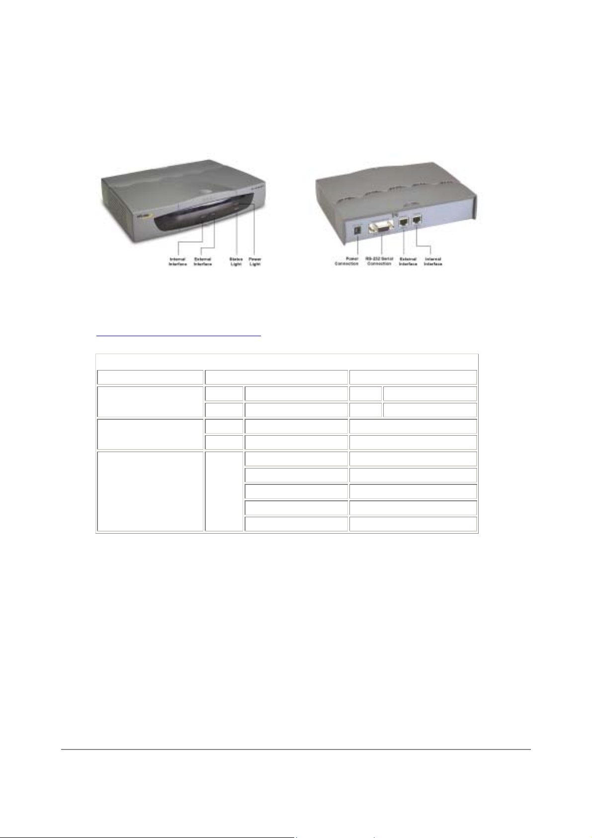
2
Front and back view of the DFL-500 NPG
Initial configuration
When the DFL-500 NPG is first powered on, it is running in NAT/Route mode and has the basic configu ration
listed in DFL-500 NPG initial power on settings
DFL-500 NPG initial power on settings
Operating mode:
Administrator account:
Internal interface:
External interface:
NAT/Route
User name: admin
Password: (none)
IP: 192.168.1.99
Netmask: 255.255.255.0
Manual:
.
IP: 192.168.100.99
Netmask: 255.255.255.0
Default Gateway: 192.168.100.1
Primary DNS Server: 207.194.200.1
Secondary DNS Ser ver: 207.194.200.129
Connecting to the web-based manager
The web-based manager is the primary tool for installing and configuring your DFL-500 NPG. Configuration
changes made with the web-based manager are effective immediately wi tho ut the need to reset the firewall or
interrupt service.
To connect to the web-based manager you need:
•
a computer with an ethernet connection,
•
Internet Explorer version 4.0 or higher,
•
a crossover cable or an ethernet hub and two ethernet cables.
To connect to the web-based manager:
• Set the IP address of the computer with an ethernet connection to the static IP address 192.168.1.2
and a netmask of 255.255.255.0.
DFL-500 User Manual
1
Page 13
3
•
Using the crossover cable or the ethernet hub and cables, connect the Internal interface of the DFL500 NPG to the computer ethernet connection.
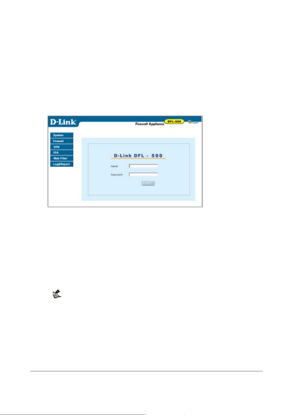
• Start Internet Explorer and browse to the address https://192.168.1.99 .
The DFL-500 login appears.
•
Type admin in the Name field and select Login.
The Register Now window appears. Use the information on this window to register your DFL-500
NPG. Register your DFL-500 NPG so that D-Link can contact you for firmware updates.
DFL-500 login
Connecting to the command line interface (CLI)
As an alternative to the web-based manager, you can install and configure the DFL-500 NPG using the CLI.
Configuration changes made with the CLI are effecti ve immediately without the need to reset the firewall or
interrupt service.
To connect to the DFL-500 CLI, you need:
•
a computer with an available communications port,
• the null modem cable included in your DFL-500 package,
• terminal emulation software such as HyperTerminal for Windows.
The following procedure describes how to connect to the DFL-500 CLI using Windows
HyperTerminal software. You can use any terminal emulation program.
•
Connect the null modem cable to the DFL-500 Console connector and to the available
communications port on y our computer.
•
Make sure that the DFL-500 NPG is powered on.
•
Start HyperTerminal, enter a name for the connection, and select OK.
•
Configure HyperTerminal to connect directly to the communications port on the computer to which
you have connected the null modem cable and select OK.
• Select the following port settings and select OK.
Bits per second
9600
DFL-500 User Manual
1
Page 14

Data bits
Parity
Stop bits
Flow control
•
Press Enter to connect to the DFL-500 CLI.
8
None
1
None
The following prompt appears:
DFL-500 login:
• Type admin and press Enter.
The following prompt appears:
Type ? for a list of commands.
For information on how to use the CLI, see the DFL-500 CLI Reference Guide .
Next steps
Now that your DFL-500 NPG is up and running, you can proceed to configure it for operation:
• If you are going to run your DFL-500 NPG in NAT/Route mo de, go to NAT/Route mode installation
• If you are going to run your DFL-500 NPG in Transparent mode, go to Transparent mode installation
.
.
DFL-500 User Manual
14
Page 15

5
NAT/Route mode installation
This chapter describes how to install your DFL-500 NPG in NAT/Route mode. If you want to install the DFL500 NPG in Transparent mode, see Transparent mode installation
This chapter includes:
•
Preparing to configure NAT/Route mode
•
Using the setup wizard
•
Using the command line interface
• Connecting to your networks
• Configuring your internal network
• Completing the configuration
Preparing to configure NAT/Route mode
Use NAT/Route mode settings to gather the information that you need to customize NAT/Route mode settings.
NAT/Route mode settings
Administrator
password:___________________________
Internal interface:
IP:
Netmask:
.
_____._____._____._____
_____._____._____._____
External interface:
Internal server
settings:
DHCP server settings:
IP:
Netmask:
Manual:
DHCP:
PPPoE:
Web Server:
SMTP Server:
POP3 Server:
IMAP Server:
FTP Server:
To allow Internet access to a Web, SMTP, POP3, IMAP or FTP server installed on your
internal network add the IP addresses of the servers above.
Starting IP:
Default Gateway:
Primary DNS Server:
Secondary DNS
Server:
If your Internet Service Provider (ISP) supplies you with an IP address using
DHCP no further information is required.
User name:_______________________
Password:________________________
If your ISP supplies you with an IP address using PPPoE, record your
PPPoE user name and password.
_____._____._____._____
_____._____._____._____
_____._____._____._____
_____._____._____._____
_____._____._____._____
_____._____._____._____
_____._____._____._____
_____._____._____._____
_____._____._____._____
_____._____._____._____
_____._____._____._____
DFL-500 User Manual
1
Page 16

6
Ending IP:
_____._____._____._____
Netmask:
Default Route:
DNS IP:
The DFL-500 NPG contains a DHCP server that you can configure to automatically set
the addresses of the computers on your internal network.
_____._____._____._____
_____._____._____._____
_____._____._____._____
Using the setup wizard
From the web-based manager, you can use the setup wizard to create the initial configura tion of your DFL500 NPG. To connect to the web-based manager, see Connecting to the web-based manager
Starting the setup wizard
• Select Easy Setup Wizard (the middle button in the upper right corner of the web-based manager).
• Use the information that you gathered in NAT/Route mode settings
the Next button to step through the wizard pages.
• Confirm your configuration settings on the last wizard page and Select Finish and Close.
If you use the setup wizard to configure internal server settings, the DFL-500 NPG adds port
forwarding virtual IPs and firewall policies for each server that you configure. For each server
located on your internal netw ork the DFL-500 NPG adds an Ext -> Int policy.
to fill in the wizard fields. Select
.
Reconnecting to the web-based manager
If you changed the IP address of the internal interface using the setup wizard, you must reco nn ect to the webbased manager using a new IP address. Browse to https:// followed by the new IP address of the internal
interface. Otherwise, you can reconnect to the web-based manager by browsing to https://192.168.1.99.
You have now completed the initial configuration of your DFL-500 NPG, and you can proceed to connect t he
DFL-500 NPG to your network using the information in Connecting to your networks
.
Using the command line interface
As an alternative to the setup wizard, you can co nfigure the DFL-500 NPG using the command line interface
(CLI). To connect to the CLI, see Connecting to the command line interface (CLI)
Configuring the DFL-500 NPG to run in NAT/Route mode
• Log into the CLI if you are not already logged in.
• Set the IP address and netmask of the internal interface to the internal IP address and netmask that
you recorded in NAT/Route mode settings
set system interface internal static ip <IP address> <netmask>
Example
set system interface internal static ip 192.168.1.1 255.255.255.0
. Enter:
.
DFL-500 User Manual
1
Page 17

7
•
Set the IP address and netmask of the external interface to the external IP address and netmask that
you recorded in NAT/Route mode settings
To set the manual IP address and netmask, enter:
set system interface external static ip <IP address> <netmask>
Example
set system interface external static ip 204.23.1.5 255.255.255.0
To set the external interface to use DHCP, enter:
set system interface external dhcp connection enable
To set the external interface to use PPPoE, enter:
set system interface external pppoe username <user name> password
<password> connection enable
Example
set system interface external pppoe username user@domain.com password
mypass connection enable
• Confirm that the addresses are correct. Enter:
get system interface
The CLI lists the IP address, netmask and other settings for each of the DFL-500 NPG interfaces as
well as the mode of the external interface (manual, DHCP, or PPPoE).
• Set the default route to the Default Gateway IP Address that you recorded in NAT/Route mode
settings (not required for DHCP and PPPoE). Enter:
set system route number <number> gw1 <IP address>
Example
set system route number 1 gw1 204.23.1.2
You have now completed the initial configuration of your DFL-500 NPG and you can proceed to connect the
DFL-500 NPG to your network using the information in Connecting to your networks
.
.
Connecting to your networks
When you have completed the initial configuration, you can connect your DFL-500 NPG between your internal
network and the Internet.
There are two 10/100 BaseTX connectors on the DFL-500 NPG:
•
Internal for connecting to your internal network,
•
External for connecting to the Internet.
To connect the DFL-500 NPG:
• Connect the Internal interface to the hub or switch connected to your internal network.
• Connect the External interface to the Internet.
Connect to the public switch or router provided by your Internet Service Provider. If you are a DSL or
cable subscriber, connect the External interface to the internal or LAN connection of your DSL or
cable modem.
DFL-500 User Manual
1
Page 18
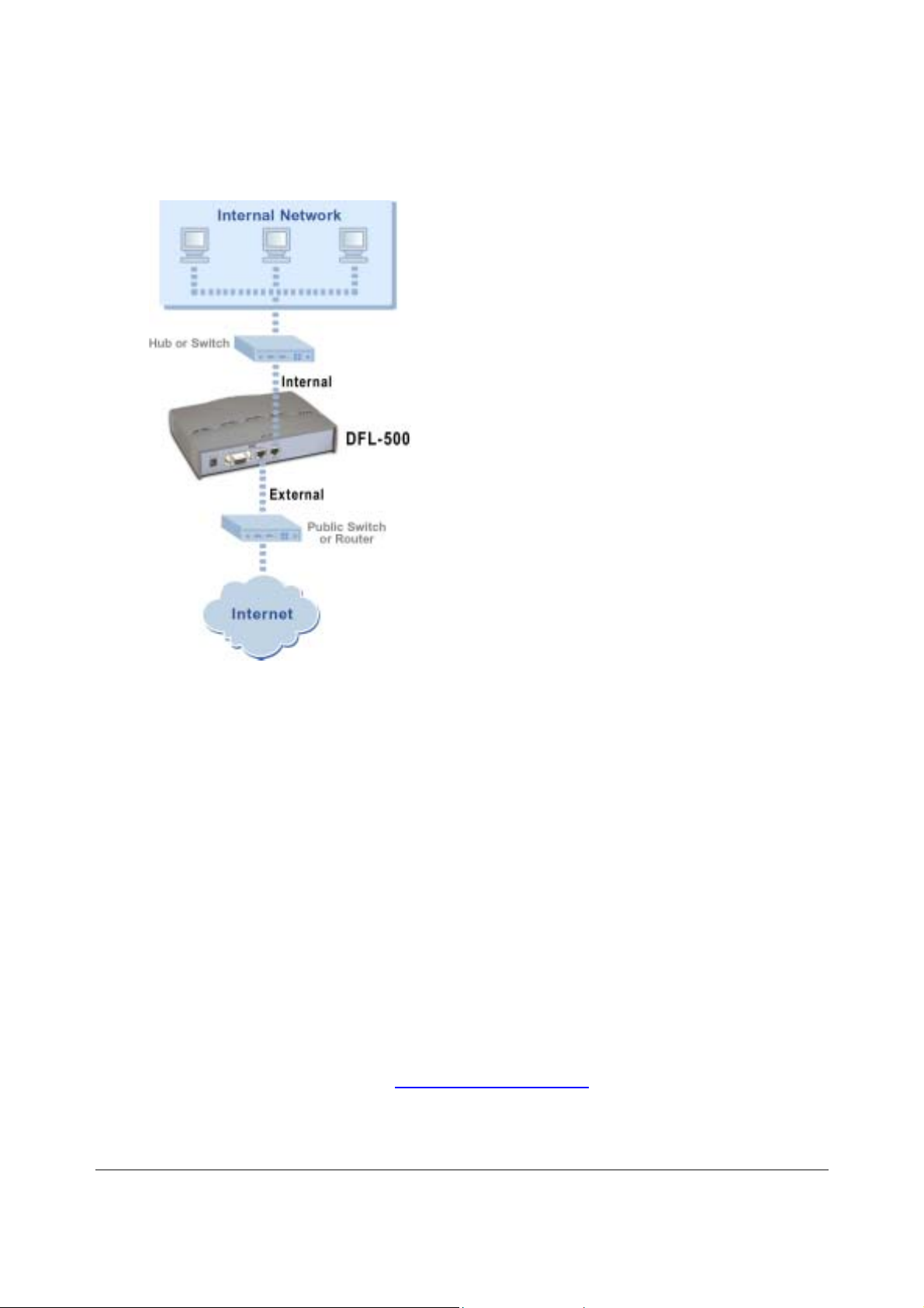
8
DFL-500 NPG network connections
Configuring your internal network
If you are running the DFL-500 NPG in NAT/Route mode, your inter nal network must be configured to route
all internet traffic to the address of the internal interface of the DFL-500 NPG. This means changing the
default gateway address of all computers connected directly to the internal network.
If you are using the DFL-500 NPG as the DHCP server for your internal network, configure the computers on
your internal network for DHCP.
When the DFL-500 NPG is connected, make sure that it is functioning properly by connecting to the Internet
from a computer on your internal network. You should be able to connect to any Internet address.
Completing the configuration
Use the information in this section to complete the initial configuration of the DFL-500 NPG.
Setting the date and time
For effective scheduling and logging, the DFL -500 NPG date and time should be accurate. You can either
manually set the DFL-500 NPG time or you can configure the DFL-500 NPG to automatically keep its time
correct by synchronizing with a Network Time Protocol (NTP) server.
To set the DFL-500 NPG date and time , see Setting system date and time
.
DFL-500 User Manual
1
Page 19

9
Transparent mode installation
This chapter describes how to install your DFL-500 NPG in Transparent mode. If you want to install the DFL500 NPG in NAT/Route mode, see NAT/Route mode installation
This chapter includes:
•
Preparing to configure Transparent mode
•
Using the setup wizard
•
Using the command line interface
• Setting the date and time
• Connecting to your network
Preparing to configure Transparent mode
Use Transparent mode settings to gather the information you need to customize Transparent mode settings.
Transparent mode settings
Administrator Password:
IP:
_____._____._____._____
.
_____._____._____._____
_____._____._____._____
_____._____._____._____
_____._____._____._____
Management
IP:
DNS Settings:
Netmask:
Default Gateway:
The management IP address and netmask must be valid for the network from which you will
manage the DFL-500 NPG. Add a default gateway if the DFL-500 NPG must connect to a router
to reach the management computer.
Primary DNS Server:
Secondary DNS
Server:
Using the setup wizard
From the web-based manager you can use the setup wizard to create the initial configuration of your DFL-500
NPG. To connect to the web-based manager, see Connecting to the web-based manager
Changing to Transparent mode
The first time that you connect to the DFL-500 NPG it is configured to run in NAT/Route mode. To switch to
Transparent mode using the web-based manager:
•
Go to System > Status .
•
Select Change to Transparent Mode.
•
Select Transparent in the Operation Mode list.
•
Select OK.
The DFL-500 NPG changes to Transp arent mo de.
To reconnect to the web-based manager, change the IP address of your management computer to 10.10.10.2.
Connect to the DFL-500 NPG internal interface and browse to https:// followed by the transparent mode
management IP address. The default transparent mode Management IP address is 10.10.10.1.
.
DFL-500 User Manual
1
Page 20

0
Starting the setup wizard
• Select Easy Setup Wizard (the button in the upper right corner of the web-based manager).
• Use the information that you gathered in Transparent mode settings
the Next button to step through the wizard pages.
• Confirm your configuration settings and then select Finish and Close.
to fill in the wizard fields. Select
Reconnecting to the web-based manager
If you changed the IP address of the management interface while you were using the setup wizard , you must
reconnect to the web-based manager using a new IP address. Browse to https:// followed by the new IP
address of the management interface. Otherwise, you can re connect to the web-based manager by browsing
to https://10.10.10.1. If you connect to the management interface through a router, make sure that you have
added a default gateway for that router to the management IP default gateway field.
Using the command line interface
As an alternative to the setup wizard, you can co nfigure the DFL-500 NPG using the command line interface
(CLI). To connect to the CLI, see Connecting to the command line interface (CLI)
you gathered in Transparent mode settings
to complete the following procedures.
Changing to Transparent mode
•
Log into the CLI if you are not already logged in.
•
Switch to Transparent mode. Enter:
set system opmode transparent
After a few seconds, the following prompt appears:
DFL-500 login:
•
•
admin
Type
The following prompt appears:
Type ? for a list of commands.
Confirm that the DFL-500 NPG has switched to Transparent mode. Enter:
get system status
The CLI displays the status of the DFL-500. The last line shows the current operation mode.
Version:DLINK-500 2.36,build075,030604
Serial Number:FGT-502801021075
Operation mode: Transparent
and press Enter.
. Use the information that
Configuring the Transparent mode management IP address
• Log into the CLI if you are not already logged in.
•
Set the IP address and netmask of the Management IP to the IP address and netmask that you
recorded in Transparent mode settings
set system management ip <IP address> <netmask>
Example
set system management ip 10.10.10.2 255.255.255.0
• Confirm that the address is correct. Enter:
get system management
DFL-500 User Manual
. Enter:
2
Page 21

The CLI lists the Management IP address and netmask.
Configure the Transparent mode default gateway
•
Login to the CLI if you are not already logged in.
•
Set the default route to the Default Gateway that you recorded in Transparent mode settings
set system route number <number> gateway <IP address>
Example
set system route number 1 gateway 204.23.1.2
You have now completed the initial configuration of the DFL-500 NPG and you can proceed to the next
section.
. Enter:
Setting the date and time
For effective scheduling and logging, the DFL -500 NPG date and time should be accurate. You can either
manually set the time or you can configure the DFL-500 NPG to automatically keep its time correct by
synchronizing with a Network Time Protocol (NTP) server.
To set the DFL-500 NPG date and time , see Setting system date and time
.
Connecting to your network
When you have completed the initial configuration, you can connect the DFL-500 NPG bet ween your internal
network and the Internet.
There are two 10/100 BaseTX connectors on the DFL-500 NPG:
• Internal for connecting to your internal network,
• External for connecting to the Internet.
To connect the DFL-500 NPG:
•
Connect the Internal interface to the hub or switch connected to your internal network.
•
Connect the External interface to the Internet.
Connect to the public switch or router provided by your Internet Service Provider.
DFL-500 User Manual
21
Page 22
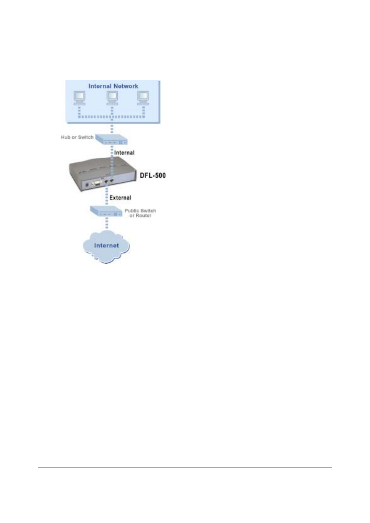
2
DFL-500 network connections
DFL-500 User Manual
2
Page 23
3
Firewall configuration
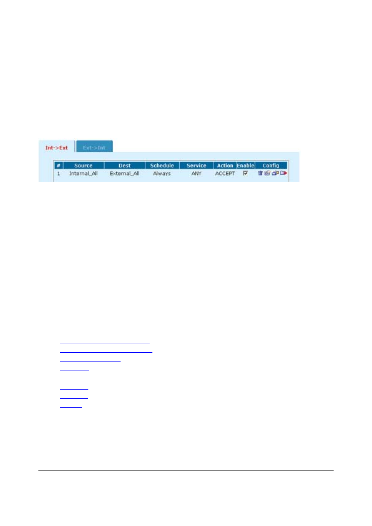
By default, the users on your internal n etwork can connect through the DFL-500 NPG to the Internet. The
firewall blocks all other connections. The firewall is configured with a default policy that matches any
connection request received from the internal network and instructs the firewall to forward the connection to
the Internet.
Default policy
Policies are instructions used by the firewall to decide what to do with a connection request. When the firewall
receives a connection request in the form of a packet, it analyzes the packet to e xtract its source address,
destination address, and service (port number).
For the packet to be connected th rough the DFL-500 NPG, you must have added a policy that matches the
packet's source address, destination address, and service. The policy directs the action that the firewall
should perform on the packet. The action can be to allow the connection, deny the connection, require
authentication before the connection is allowed, or process the packet as an IPSec VPN packet.
You can enable and disable policies. You can add schedules to policies so that the firewall can process
connections differently depending on the time of day or the day of the week, month, or year. You can also
enable web content filtering for policies that control the HTTP service.
Use Int -> Ext policies to control how users on your internal network access the In ternet. You can use these
policies to apply web content filtering to protect users on your internal net work from downloading unwanted
content from the Internet. You can also use these policies to control IPSec VPN connections through the
firewall.
Use Ext -> Int policies to control connections from the Internet to your internal network. You can use these
policies to apply web content filtering. You can also use these policies to allow remote users to connect to
your internal network using PPTP and L2TP VPN.
This chapter describes:
•
NAT/Route mode and Transparent mode
•
Adding NAT/Route mode policies
•
Adding Transparent mode policies
•
Configuring policy lists
•
Addresses
•
Services
•
Schedules
•
Virtual IPs
•
IP pools
•
IP/MAC binding
DFL-500 User Manual
2
Page 24

NAT/Route mode and Transparent mode
The first step in configuring firewall policies is to configure the mode for the firewall. The firewall can run in
NAT/Route mode or Transparent mode.
NAT/Route mode
Run the DFL-500 NPG in NAT/Route mode to protect a private network from a public network. When the
DFL-500 NPG is running in NAT/Route mode, you can conne ct a private ne twork to the internal inte rface and
a public network, such as the Internet, to the external interface. Each of these networks must have a different
subnet address. You create policies to control how the firewall routes packets between interfaces, and
therefore between the networks connected to the interfaces.
In NAT/Route mode, you can create NAT mode policies and Route mode policies.
• NAT mode policies use network address translation to hide the addresses of a more secure network
from users on a less secure network.
•
Route mode policies control connections between networks without performing address translation.
Transparent mode
Run the DFL-500 NPG in Transparent mode to provide firewall protection to a network with pub lic addresses.
The DFL-500 NPG can be inserted into your network at any point wi thout the need to make changes to y our
network or any of its components.
In Transparent mode, you add policies to accept or deny connections between interfaces. The DFL-500 NPG
applies policies to control network traffic without modifying the packets in any way.
Changing to Transparent mode
Use the procedure Changing to Transparent mode to switch the DFL-500 NPG from NAT/Route mode to
Transparent mode.
Changing to Transparent mode deletes all NAT/Route mode policies and addresses. In addition any routing
set in NAT mode is also deleted. This includes the default route that is part of the default NAT configuration.
Changing to NAT/Route mode
Use the procedure Changing to NAT/Route mode to switch the DFL-500 NPG from Transparent mode to
NAT/Route mode.
Changing to NAT/Route mode deletes all Transparent mode policies and addresses. In addition any routing
set in NAT mode is also deleted. This includes the default route that is part of the default NAT configuration.
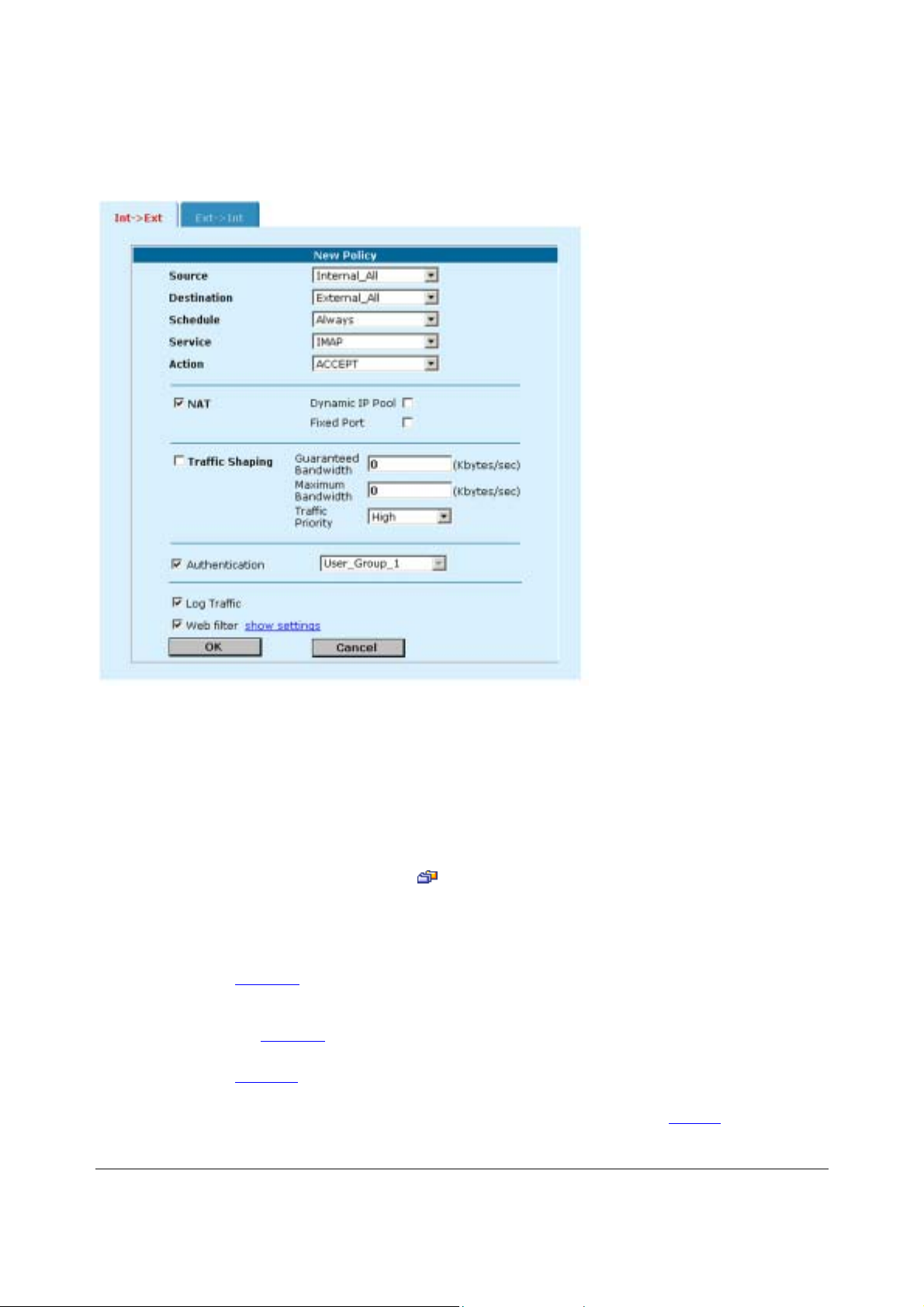
Adding NAT/Route mode policies
Add NAT/Route mode policies to control connections and traffic between DFL-500 interfaces. If you have
configured the DFL-500 NPG for NAT/Route mode operation, you can use the following procedure to add
NAT/Route mode policies:
•
Go to Firewall > Policy .
•
Select the policy list tab to which you want to add the policy.
•
Select New to add a new policy.
DFL-500 User Manual
24
Page 25

5
You can also select Insert Policy before on a policy in the list to add the new policy above a
specific policy.
•
Configure the policy:
Source
Destination
Schedule
Service
Action
ACCEPT
DENY
ENCRYPT
NAT
Dynamic IP
Pool
Fixed Port
VPN Tunnel
Allow
inbound
Allow
outbound
Inbound
NAT
Outbound
NAT
Log Traffic
Authentication
Select an address or address group that matches the source address of the packet. Before you
can add this address to a policy, you must add it to the source interface. To add an address, see
Addresses
Select an address or address group that matches the destination address of the packet. Before
you can add this address to a policy, you must add it to the source interface. To add an address,
see Addresses
For an Ext -> Int NAT mode policy, the destination can also be a virtual IP that maps the
destination address to a hidden destination address on the internal network. See Virtual IPs
Select a schedule that controls when the policy is available to be matched with connections. See
Schedules
Select a service that matches the service (or port number) of the packet. You can select from a
wide range of predefined services or add custom services and service groups. See Services
Select how the firewall should respond when the policy matches a connection attempt.
Accept the connection. If you select ACCEPT, you can also configure NAT and Authentication for
the policy.
Deny the connection.
Make this policy an IPSec VPN policy. If you select ENCRYPT, you can select an AutoIKE key or
Manual Key VPN tunnel for the policy and configure other IPSec settings. For ENCRYPT policies,
service is set to ANY and authentication is not supported
Configure the policy for NAT. NAT translates the source address and the source port of packets
accepted by the policy. If you select NAT, you can also select Dynamic IP Pool and Fixed Port.
Select Dynamic IP Pool to translate the source address to an address randomly selected from an
IP pool added to the destination interface of the policy. To add IP pools, see IP pools
You cannot select Dynamic IP Pool for Int -> Ext policies if the external interface is configured
using DHCP or PPPoE.
Select Fixed Port to prevent NAT from translating the source port. Some applications do not
function correctly if the source port is changed. If you select Fixed Port, you must also select
Dynamic IP Pool and add a dynamic IP pool address range to the destination interface of the
policy. If you do not select Dynamic IP Pool, a policy with Fixed Port selected can only allow one
connection at a time for this port or service.
Select a VPN tunnel for an ENCRYPT policy. You can select an AutoIKE key or Manual Key
tunnel.
Select Allow inbound so that users behind the remote VPN gateway can connect to the source
address.
Select Allow outbound so that users can connect to the destination address behind the remote
VPN gateway.
Select Inbound NAT to translate the source address of incoming packets to the DFL-500 NPG
internal IP address.
Select Inbound NAT to translate the source address of outgoing packets to the DFL-500 NPG
external IP address.
Select Log Traffic to write messages to the traffic log whenever the policy processes a connection.
Select Authentication and select a user group to require users to enter a user name and password
before the firewall accepts the connection. Select the user group to select the users that can
authenticate with this policy. To add and configure user groups, see Users and authentication
must add user groups before you can select authentication.
.
.
.
.
.
.
. You
DFL-500 User Manual
2
Page 26

6
Telnet, or FTP. For users to be able to authenticate you must add an HTTP, Telnet, or FTP policy
that is configured for authentication. When users attempt to connect through the firewall using this
policy they are prompted to enter a firewall username and password.
If you want users to authenticate to use other services (for example POP3 or IMAP) you can create
a service group that includes the services for which you want to require authentication as well as
HTTP, Telnet, and FTP. Then users could authenticate with the policy using HTTP, Telnet, or FTP
before using the other service.
In most cases you should make sure that users can use DNS through the firewall without
authentication. If DNS is not available users cannot connect to a web, FTP, or Telnet server using
a domain name.
Enable web filter content filtering for traffic controlled by this policy. You can select Web filter if
Service is set to ANY or HTTP or to a service group that includes the HTTP service.
Web filter
For web filter content filtering to take effect, you must configure web content filtering. See Web
content filtering.
You can select show settings to display the current web filter content filtering settings for the DFL500 NPG.
• Select OK to add the policy.
The policy is added to the selected policy list.
•
Arrange policies in the policy list so that they have the results that you expect.
See Configuring policy lists
for more information.
DFL-500 User Manual
2
Page 27
7
Adding a NAT/Route Int -> Ext policy
Adding Transparent mode policies
Add Transparent mode policies to control the net work traffic that is allowed to pass through the firewall when
you are running the it in Transparent mode.
• Go to Firewall > Policy .
• Select a policy list tab.
• Select New to add a new policy.
You can also select Insert Policy before
specific policy.
• Configure the policy:
Source
Destination
Schedule
Service
Select an address or address group that matches the source address of the packet. Before you
can add this address to a policy, you must add it to the source interface. To add an address, see
Addresses
Select an address or address group that matches the destination address of the packet. Before
you can add this address to a policy, you must add it to the source interface. To add an address,
see Addresses
A schedule that controls when this policy is available to be matched with connections. See
Schedules
A service that matches the service (port number) of the packet. You can select from a wide range
of predefined services, or add custom services and service groups. See Services
.
.
.
on a policy in the list to add the new policy above a
.
DFL-500 User Manual
2
Page 28

8
Action
Log Traffic
Authentication
Web filter
Select how the firewall should respond when the policy matches a connection attempt. You can
configure the policy to direct the firewall to ACCEPT the connection or DENY the connection. If
you select ACCEPT, you can also configure Authentication for the policy.
Select Log Traffic to write messages to the traffic log whenever the policy processes a
connection.
Select Authentication and select a user group to require users to enter a user name and
password before the firewall accepts the connection. Select the user group to select the users
that can authenticate with this policy. To add and configure user groups, see Users and
authentication. You must add user groups before you can select authentication.
You can select Authentication for any service. Users can authenticate with the firewall using
HTTP, Telnet, or FTP. For users to be able to authenticate you must add an HTTP, Telnet, or
FTP policy that is configured for authentication. When users attempt to connect through the
firewall using this policy they are prompted to enter a firewall username and password.
If you want users to authenticate to use other services (for example POP3 or IMAP) you can
create a service group that includes the services for which you want to require authentication as
well as HTTP, Telnet, and FTP. Then users could authenticate with the policy using HTTP,
Telnet, or FTP before using the other service.
In most cases you should make sure that users can use DNS through the firewall without
authentication. If DNS is not available users cannot connect to a web, FTP, or Telnet server using
a domain name.
Enable web filter content filtering for traffic controlled by this policy. You can select Web filter if
Service is set to ANY or HTTP, or to a service group that includes the HTTP service.
For web filter content filtering to take effect, you must configure web content filtering. See Web
content filtering
You can select show settings to display the current web filter content filtering settings for the DFL500 NPG.
.
• Select OK to add the policy.
The policy is added to the selected policy list.
• Arrange policies in the policy list so that they have the results that you expect.
Arranging policies in a policy list is described in Configuring policy lists
.
DFL-500 User Manual
2
Page 29
9
Adding a Transparent mode Int -> Ext policy
Configuring policy lists
The firewall matches policies by searching for a match starting at the top of the policy list and moving down
until it finds the first match. You must arrange policies in the policy list from more specific to more general.
For example, the default policy is a very general policy because it matches all co nnection attempts. To cre ate
exceptions to this policy, they must be added to the policy list above the default policy. No policy below the
default policy will ever be matched.
This section describes:
• Policy matching in detail
• Changing the order of policies in a policy list
• Enabling and disabling policies
Policy matching in detail
When the firewall receives a connection attempt at an interface, it must matc h the connection attempt to a
policy in either the Int -> Ext or Ext -> Int policy list. The firewall starts at the top of the policy list for the
interface that received the connection attempt and searches do wn the list for the first policy that matches the
connection attempt source and destination addresses, service port, and time and date at which the
connection attempt was received. The first policy that matches is applied to the connection attempt. If no
policy matches, the connection is dropped.
The default policy accepts all connection a ttempts from th e internal network to the Inter net. From the internal
network, users can browse the web, use POP3 to get ema il, use FTP to download files through the firewall,
and so on. If the default policy is at the t op of the Int -> Ext policy list, the firewall allo ws all connections from
the internal network to the Internet because all connections match the default policy.
A policy that is an exception to the default po licy, for example, a policy to block FTP connections, must be
placed above the default policy in the Int -> Ext policy list. In this exam ple, all FTP connection attempts fr om
the internal network would then match the FTP policy and be blocked. Connection attempts for all other kinds
of services would not match with the FTP policy but they would match with the default policy. Ther efore, the
firewall would still accept all other connections from the internal network.
DFL-500 User Manual
2
Page 30

0
Policies that require authentication must be added to the policy list above matching policies that do not;
otherwise, the policy that does not require authentication is selected first.
Changing the order of policies in a policy list
• Go to Firewall > Policy .
• Select the tab for the policy list that you want to rearrange.
• Choose a policy to move and select Move To
• Type a number in the Move to field to specify where in the policy list to move the policy and select OK.
• Select Delete
to remove a policy from the list.
to change its order in the policy list.
Enabling and disabling policies
You can enable and disable policies in the policy list to control whether the policy is active or not. The firewall
matches enabled policies but does not match disabled policies.
Disabling a policy
Disable a policy to temporarily prevent the firewall from selecting the policy.
• Go to Firewall > Policy .
• Select the tab for the policy list containing the policy to disable.
• Clear the check box of the policy to disable.
Enabling a policy
Enable a policy that has been disabled so that the firewall can match connections with the policy.
•
Go to Firewall > Policy .
•
Select the tab for the policy list containing the policy to enable.
•
Select the check box of the policy to enable.
Addresses
All policies require source and destination addresses. To add an address to a policy between two inter faces,
you must first add addresses to the address list for each interface. Thes e addresses must be valid addresses
for the network connected to that interface.
By default, the firewall includes two addresses that cannot be edited or deleted:
• Internal_All on the internal address list represents the IP addresses of all computers on your internal
network.
• External_All on the external address list represents the IP addresses of all computers on the Internet.
You can add, edit, and delete all o ther addresses as required. You can also organize related addre sses into
address groups to simplify policy creation.
This section describes:
•
Adding addresses
•
Deleting addresses
•
Organizing addresses into address groups
DFL-500 User Manual
3
Page 31

Adding addresses
• Go to Firewall > Address .
• Select the interface to which to add the address.
The list of addresses added to that interface is displayed.
•
Select New to add a new address to the selected interface.
•
Enter an Address Name to identify the address.
The name can contain numbers (0-9), uppercase and lowercase letters (A-Z, a-z), and the special
characters - and _. Spaces and other special characters are not allowed.
Adding a firewall address
• Enter the IP Address.
The IP address can be the IP address of a single computer (for example, 192.45.46.45) or the
address of a subnetwork (for example, 192.168.1.0).
The address must be a valid address for one of the networks or computers connected to the interface.
• Enter the NetMask.
The netmask should correspond to the address. The netmask for the IP address of a single computer
should be 255.255.255.255. The netmask f or a subnet should be 255.255.255.0.
• Select OK to add the address.
Deleting addresses
Delete an address to make it unavailable for use by policies. If an address is included in any policy, it cannot
be deleted unless it is first removed from the policy.
•
Go to Firewall > Address .
•
Select the interface list containing the address that you want to delete.
You can delete any listed address that has a Delete Address icon
• Choose an address to delete and select Delete
• Select OK to delete the address.
.
.
DFL-500 User Manual
31
Page 32

2
Organizing addresses into address groups
You can organize related addresses into address groups to make it easier to add policies. For example, if you
add three addresses, and then add them to an address group, you only have to add one policy for the
address group rather than three separate policies, one for each address.
You can add address groups to both interfaces. The address group can only contain addresses from that
interface. Address groups are available in interface source or destination address lists.
Address groups cannot have the same names as in dividual addresses. If an address group is included in a
policy, it cannot be deleted unless it is first removed from the policy.
• Go to Firewall > Address > Group .
• Select the interface list to which to add the address group: New Int Group, or New Ext Group.
Adding an internal address group
• Enter a Group Name to identify the address group.
The name can contain numbers (0-9), uppercase and lowercase letters (A-Z, a-z), and the special
characters - and _. Other special characters and spaces are not allowed.
• To add addresses to the address group, select an address from the Available Addresses list and
select the right arrow to add it to the Members list.
•
To remove addresses from the address group, select an address from the Members list and select
the left arrow to remove it from the group.
•
Select OK to add the address group.
Services
Use services to control the types of communication accepted or denied by the firewall. You can add any of the
predefined services to a policy. You can also create your own custom services and add services to service
groups.
This section describes:
DFL-500 User Manual
3
Page 33

3
•
Predefined services
•
Providing access to custom services
•
Grouping services
Predefined services
To view the list of predefined services, go to Firewall > Service > Pre-defined . You can add predefined
services to any policy.
Providing access to custom services
Add a custom service if you need to create a policy for a service that is not in the predefined service list.
• Go to Firewall > Service > Custom .
•
Select New.
• Enter a Name for the service. This name appears in the service list used when you add a policy.
The name can contain numbers (0-9), uppercase and lower case letters (A-Z, a-z), and the special
characters - and _. Other special characters and spaces are not allowed.
•
Select the Protocol (either TCP or UDP) used by the service.
• Specify a Source and Destination Port number range for the service by entering the low and high port
numbers. If the service uses one port number, e nter this number into both the low and high fields.
•
If the service has more than one port range, select Add to specify additional protocols and port
ranges.
If you mistakenly add too many port range rows, select Delete
to remove each extra row.
•
Select OK to add the custom service.
You can now add this custom service to a policy.
Grouping services
To make it easier to add policies, you can create groups of services and then add one policy to provide
access to or block access for all the services in the group. A service group can contain predefined services
and custom services in any combination. You cannot add service groups to another service group.
To add a service group:
• Go to Firewall > Service > Group .
•
Select New.
• Enter a Group Name to identify the group.
This name appears in the service list when you add a policy and cannot be the same as a predefined
service name.
The name can contain numbers (0-9), upper case and lower case letters (A-Z, a-z), and the special
characters - and _. Other special characters and spaces are not allowed.
DFL-500 User Manual
3
Page 34

Adding a service group
•
To add services to the service group, select a service from the Available Services list and select the
right arrow to copy it to the Members list.
• To remove services from the service group, select a service from the Members list and select the left
arrow to remove it from the group.
•
Select OK to add the service group.
Schedules
Use scheduling to control when policies are active or inactive. You can create one-time schedules and
recurring schedules. You can use one-time schedules to create policies that are effective once for the period
of time specified in the schedule. Recurring schedules repeat weekly. You can use recurring schedules to
create policies that are effective only at specified times of the day or on specified days of the week.
This section describes:
•
Creating one-time schedules
•
Creating recurring schedules
•
Adding a schedule to a policy
Creating one-time schedules
You can create a one-time schedule that activates or deactivates a po licy for a specified period of time. For
example, your firewall might be configured with the default Internal to Externa l policy that allows access to all
services on the Internet at all times. You can add a one-time schedule to block access to th e Interne t during a
holiday period.
• Go to Firewall > Schedule > One-time .
• Select New.
•
Enter a Name for the schedule.
The name can contain numbers (0-9), uppercase and lower case letters (A-Z, a-z), and the special
characters - and _. Other special characters and spaces are not allowed.
DFL-500 User Manual
34
Page 35

5
•
Set the Start date and time for the schedule.
Set Start and Stop times to 00 for the schedule to cover the entire day.
• Set the Stop date and time for the schedule.
One-time schedules use the 24-hour clock.
•
Select OK to add the one-time schedule.
Creating recurring schedules
You can create a recurring schedule that activates or d eactivates policies at specified times of the day or on
specified days of the week. For example, if your DFL-500 NPG is protecting a home office, you may wish to
provide access to different services during working hours than you do on evenings and weekends.
If you create a recurring schedule with a stop time that occurs before the start time, the schedule will start at
the start time and finish at the stop time on the next day. You can use this technique to create recurring
schedules that run from one day to the next. You can also create a recurring schedule that runs for 24 hours
by setting the start and stop times to the same time.
•
Go to Firewall > Schedule > Recurring .
• Select New to create a new schedule.
• Enter a Name for the schedule.
The name can contain numbers (0-9), uppercase and lower case letters (A-Z, a-z), and the special
characters - and _. Other special characters and spaces are not allowed.
• Select the days of the week on which the schedule should be active.
• Set the Start and Stop hours in between which the schedule should be active.
Recurring schedules use the 24-hour clock.
•
Select OK.
Adding a schedule to a policy
After you have created schedules, you can add them to policies to schedule when the policies are active. You
can add the new schedules to policies when you create the policy, o r you can edit existing policies and ad d a
new schedule to them.
Arrange the policy in the policy list to have the effect that you expect. For example, to use a one-time
schedule to deny access to a policy, add a policy that matches the policy to be denied in every way. Choose
the one-time schedule that you added and set Action to DENY. Then p lace the policy con taining the one-time
schedule in the policy list above the policy to be denied.
Virtual IPs
NAT mode security policies hide the addresses of more secure networks from less secure networks. To allow
connections from a less secure network to an address in a more secure network, you must create an external
address in the less secure network and map that address to a real address in the more secure network. This
association is called a virtual IP.
For example, if the computer hosting your web server is located on your internal network, it could have a
private IP address such as 192.168.1.10. To get packets from the Internet to your web server, you must
DFL-500 User Manual
3
Page 36

6
create an external address for the web server on the Internet. You must then add a virtual IP to the firewall
that maps the external IP address of the web server to the actual address of the web server on your internal
network. To allow connections from the Internet to the web server, you must then add an Ext -> Int firewall
policy and set Destination to the virtual IP.
You can create two types of virtual IPs:
Static NAT
Port
Forwarding
Used in Ext -> Int policies to translate an address on the Internet to a hidden address on the internal
network. Static NAT translates the source address of outbound packets to the address to the
address on the Internet.
Used in Ext -> Int policies to translate an address and a port number on a less secure network to a
hidden address and, optionally, a different port number on a more secure network. Using port
forwarding you can also route packets with a specific port number and a destination address that
matches the IP address of the interface that receives the packets. This technique is called port
forwarding or port address translation (PAT). You can also use port forwarding to change the
destination port of the forwarded packets.
If you use the setup wizard to configure internal server settings, the firewall adds port forwarding virtual
IPs and Ext -> Int policies for each server that you configure.
Virtual IPs are not required in Transparent mode.
This section describes:
•
Adding static NAT virtual IPs
•
Using port forwarding virtual IPs
•
Adding policies with virtual IPs
Adding static NAT virtual IPs
•
Go to Firewall > Virtual IP .
• Select New to add a virtual IP.
• Enter a Name for the virtual IP.
The name can contain numbers (0-9), uppercase and lowercase letters (A-Z, a-z), and the special
characters - and _. Other special characters and spaces are not allowed.
• Make sure Type is set to Static NAT.
•
In the External IP Address field, enter the external IP address to be mapped to an address on the
internal network.
For example, if the virtual IP provides access from the Internet to a web server on your internal
network, the external IP address must be a static IP address obtained from your ISP for your web
server. This address must be a unique address tha t is no t used by another host and cannot be the
same as the IP address of the firewall external interface. H owever, this address must be routed to the
firewall external interface.
DFL-500 User Manual
3
Page 37

7
Adding a static NAT virtual IP
• In the Map to IP field, enter the real IP address on the more secure network, for example, the IP
address of a web server on your internal network.
The firewall translates the source address of outbound packets from the host with the Map to IP address to
the virtual IP External IP Address, instead of the firewall external address.
•
Select OK to save the virtual IP.
You can now add the virtual IP to Ext -> Int firewall policies.
Using port forwarding virtual IPs
• Go to Firewall > Virtual IP .
•
Select New to add a virtual IP.
•
Enter a Name for the virtual IP.
The name can contain numbers (0-9), uppercase and lowercase letters (A-Z, a-z), and the special
characters - and _. Other special characters and spaces are not allowed.
•
Change Type to Port Forwarding.
• In the External IP Address field, enter the external IP address to be mapped to an address in the
more secure zone.
You can set the External IP Address to the address of external interface or to any other address.
For example, if the virtual IP provides access from the Internet to a server on your internal netwo rk,
the External IP Address must be a static IP address obtained from your ISP for this server. This
address must be a unique address that is not used by another host. However, this address must be
routed to the firewall external interface.
DFL-500 User Manual
3
Page 38

8
Adding a Port Forwarding virtual IP
• Enter the External Service Port number for which to configure port forwarding.
The external service port number must match the destination port of the packets to be forwarded. For
example, if the virtual IP provides access from the Internet to a Web server on your internal network,
the external service port number would be 80 (the HTTP port).
• In Map to IP, enter the real IP address on the more secure network, for example, the IP address of a
web server on your internal network.
• Set Map to Port to the port number to be ad ded to packets when they are forwarded.
If you do not want to translate the port, enter the same number as the External Service Port.
If you want to translate the port, enter the port number to which to translate the destination port of the
packets when they are forwarded by the firewall.
• Select the protocol to be used by the forwarded packets.
• Select OK to save the port forwarding virtual IP.
Adding policies with virtual IPs
Use the following procedure to add a policy that uses a virtual IP to forward packets.
•
Go to Firewall > Policy > Ext -> Int .
• Use the following information to configure the policy.
Source
DFL-500 User Manual
Select the source address from which users can access the server. For example, if you want to
add a policy that allows all users on the Internet to access a server set Source to External_All.
3
Page 39

9
Destination
Schedule
Service
Action
NAT
Authentication
Log Traffic
Web filter
•
Select OK to save the policy.
Select the virtual IP.
Select a schedule as required.
Select the service that matches the Map to Service that you selected for the port-forwarding
virtual IP.
Set action to ACCEPT to accept connections to the internal server. You can also select DENY to
deny access.
Select NAT if the firewall is protecting the private addresses on the destination network from the
source network.
Optionally select Authentication and select a user group to require users to authenticate with the
firewall before accessing the server using port forwarding.
Select these options to log port-forwarded traffic and apply web filter protection to this traffic.
IP pools
An IP pool (also called a dynamic IP pool) is a range of IP addresses added to a firewall interface. The
addresses in the IP pool must be on the same subnet as the IP address of the interface. You can add multiple
IP pools to each interface.
Add an IP pool if you want to add NAT mode policies that translate source addresses to addresses randomly
selected from a predefined range of IP addresses. For example, if the IP address of the internal interface is
192.168.1.99, a valid IP pool could have a start IP of 192.16 8.1.10 and an end IP of 192.168.1.20. This IP
pool would give the firewall 11 addresses to select from when translating the source address.
If you add IP pools for an interface, you can sele ct Dynamic IP Pool when you configure a policy with its
destination set to this interface. If you add IP pools for the internal interface, you can select IP pools for Ext ->
Int policies.
To add an IP pool:
• Go to Firewall > IP Pool.
• Select the interface to which to add the IP pool.
The list of IP pools added to that interface is displayed.
•
Select New to add a new IP pool to the selected interfac e.
• Enter the Start IP and End IP address for the range of addresses in the IP pool.
The Start IP and End IP must define the start and end of an address range. The Start IP must be
lower than the End IP. The Start IP and End IP must be on the same subnet as the IP address of the
interface for which you are adding the IP pool.
If you have configured the external interface to use PPPoE or DHCP you can only set the Start IP and
End IP to the current IP address of the external interface.
•
Select OK.
The IP pool can be added to NAT policies with a destination that is the interface to which you have
added the IP pool. For example, IP pools for the external interface can be added to Int -> Ext policies.
DFL-500 User Manual
3
Page 40

0
Adding an IP Pool
IP/MAC binding
IP/MAC binding protects the DFL-500 NPG and your network from IP spoofing attacks. IP spoofing attempts
to use the IP address of a trusted computer to connect to or through the firewall from a different computer.
The IP address of a computer can easily be changed to a trusted address, but MAC addresses are added to
ethernet cards at the factory and cannot easily be changed.
You can enter the static IP addresses and corresponding MAC addr esses of trusted computers in the Static
IP/MAC table.
If you have trusted computers with dynamic IP addresses that are set by the DFL-500 DHCP server, the
firewall adds these IP addresses and their corresponding MAC addresses to the Dynamic IP/MAC tabl e. See
Providing DHCP services to your internal network
Transparent mode.
IP/MAC binding can be enabled for packets connecting to the firewall or passing through the firewall.
If you enable IP/MAC binding and change the IP address of a computer with an IP address or MAC address
in the IP/MAC list, you must also change the entry in the IP/MAC list or the computer will not have access to
or through the firewall. You must also add the IP/MAC address pair of any new computer that you add to your
network or this computer will not have access to or through the firewall.
This section describes:
• Configuring IP/MAC binding for packets going through the firewall
• Configuring IP/MAC binding for packets going to the firewall
• Adding IP/MAC addresses
• Viewing the dynamic IP/MAC list
• Enabling IP/MAC binding
. The dynamic IP/MAC binding table is not available in
Configuring IP/MAC binding for packets going through the firewall
Use the following procedure to use IP/MAC binding to filter packets that would normally be matched with
firewall policies to be able to go through the firewall.
•
Go to Firewall > IP/MAC Binding > Setting .
• Select Enable IP/MAC binding going through the firewall.
•
Go to Firewall > IP/MAC Binding > Static IP/MAC .
•
Select New to add IP/MAC binding pairs to the IP/MAC binding list.
DFL-500 User Manual
4
Page 41

All packets that would normally be matched with policies to be able to go through the firewall are first
compared with the entries in the IP/MAC binding list. If a match is found, then the firewall attempts to match
the packet with a policy.
For example, if the IP/MAC pair IP 1.1.1.1 and 12:34:56:78:90:ab:cd is added to the IP/MAC binding list:
•
A packet with IP address 1.1.1.1 and MAC address 12:34:56:78:90:ab:cd is allowed to go on to be
matched with a firewall policy.
•
A packet with IP 1.1.1.1 but with a different MAC address is dropped immediately to prevent IP
spoofing.
• A packet with a different IP address but with a MAC address of 12:34:56:78:90:ab:cd is dropped
immediately to prevent IP spoofing.
• A packet with both the IP address and MAC address not defined in the IP/MAC binding table:
• is allowed to go on to be matched with a firewall policy if IP/MAC binding is set to Allow traffic,
• is blocked if IP/MAC binding is set to Block traffic.
Configuring IP/MAC binding for packets going to the firewall
Use the following procedure to use IP/MAC binding to filter packets that would normally connect with the
firewall (for example when an administrator is connecting to the DFL-500 NPG for management).
• Go to Firewall > IP/MAC Binding > Setting .
•
Select Enable IP/MAC binding going to the firewall.
•
Go to Firewall > IP/MAC Binding > Static IP/MAC .
• Select New to add IP/MAC binding pairs to the IP/MAC binding list.
All packets normally allowed to connect to the firewall are compared with the entries in the IP/MAC binding
table. If a match is found in the IP/MAC binding table:
• If IP/MAC binding is set to Allow traffic, then IP/MAC binding allows the packet to connect to the
firewall.
• If IP/MAC binding is set to Block traffic, then IP/MAC binding stops the packet from connecting to the
firewall.
Adding IP/MAC addresses
•
Go to Firewall > IP/MAC Binding > Static IP/MAC .
•
Select New to add an IP address/MAC ad dre ss pair.
• Enter the IP address and the MAC address.
You can bind multiple IP addresses to the same MAC address. You cannot bind multiple MAC
addresses to the same IP address.
However, you can set the IP address to 0.0.0.0 for multiple MAC addresses. This means that all
packets with these MAC addresses are matched with the IP/MAC binding list.
Similarly, you can set the MAC address to 00:00:00:00:00:00 for multiple IP addresses. This means
that all packets with these IP addresses are matched with the IP/MAC binding list.
•
Enter a Name for the new IP/MAC address pair.
The name can contain numbers (0-9), uppercase and lowercase letters (A-Z, a-z), and the special
characters - and _. Other special characters and spaces are not allowed.
•
Select Enable to enable IP/MAC binding for the IP/MAC pair.
• Select OK to save the IP/MAC binding pair.
DFL-500 User Manual
41
Page 42

2
Viewing the dynamic IP/MAC list
• Go to Firewall > IP/MAC Binding > Dynamic IP/MAC .
Enabling IP/MAC binding
• Go to Firewall > IP/MAC Binding > Setting .
• Select Enable IP/MAC binding going through the firewall to turn on IP/MAC binding for packets that
could be matched by policies.
•
Select Enable IP/MAC binding going to the firewall to turn on IP/MAC binding for packets connecting
to the firewall.
•
Configure how IP/MAC binding handles packets with IP and MAC addresses that are not defined in
the IP/MAC list.
Select Allow traffic to allow all packets with IP and MAC address pairs that are not added to the
IP/MAC list.
Select Block traffic to block packets with IP and MAC address pairs that are not added to the IP/MAC
binding list.
• Select Apply to save your changes.
IP/MAC settings
DFL-500 User Manual
4
Page 43

3
Users and authentication
DFL-500 NPGs support user authentication to the DFL-500 user database or to a RADIUS server. You can
add user names to the DFL-500 user data base and then add a password to allow the user to authenticate
using the internal database. You can also add the name of a RADIUS server and select RADIUS to allow the
user to authenticate using the selected RADIUS server. You can also disable users so that they cannot
authenticate with the DFL-500 NPG.
To enable authentication, you must add user names to one or more user groups. You can al so add RADIUS
servers to user groups. You can then select a user group when you require authentication.
You can require authentication for:
• any firewall policy with Action set to ACCEPT (see Adding NAT/Route mode policies
NAT/Route mode policies)
•
IPSec dialup remote gateways (see Adding a remote gateway
•
PPTP (see PPTP VPN configuration
• L2TP (see L2TP VPN configuration
When a user enters a user name and password, the DFL-500 NPG searches the internal user database for a
matching user name. If Disable is selected for that user name, the user cannot authenticate and the
connection is dropped. If Password is selected for t hat user and the password matches, the connection is
allowed. If the password does not match, the connection is dropped.
If RADIUS is selected and RADIUS support is configured and the user name and password match a user
name and password on the RADIUS server, the connection is allowed. If the user name and password do not
match a user name and password on the RADIUS server, the connection is dropped.
This chapter describes:
•
Setting authentication time out
•
Adding user names and configuring authentication
•
Configuring RADIUS support
•
Configuring user groups
)
)
)
and Adding
Setting authentication time out
To set authentication time out using the web-based manager:
• Go to System > Config > Options .
• Set Auth Timeout to control how long authenticated firewall connections can remain idle before users
must authenticate again to get access through the firewall.
The default authentication time out is 15 minutes.
Adding user names and configuring authentication
Use the following procedures to add user names and configure authentication.
This section describes:
•
Adding user names and configuring authentication
•
Deleting user names from the internal database
Adding user names and configuring authentication
•
Go to User > Local .
DFL-500 User Manual
4
Page 44

•
Select New to add a new user name.
Adding a user name
•
Enter the user name.
The user name can contain numbers (0-9) and uppercase and lowercase letters (A-Z, a-z), and the
special characters - and _. Other special characters and spaces are not allowed.
• Select one of the following authentication configurations:
Disable
Password
RADIUS
Prevent this user from authenticating.
Enter the password that this user must use to authenticate. The password should be at least six
characters long. The password can contain numbers (0-9), uppercase and lowercase letters (A-Z,
a-z), and the special characters - and _. Other special characters and spaces are not allowed.
Require the user to authenticate to a RADIUS server. Select the name of the RADIUS server to
which the user must authenticate. You can only select a RADIUS server that has been added to
the DFL-500 RADIUS configuration. See Configuring RADIUS support
.
• Select Try other servers if connect to selected server fails if you want the DFL-500 NPG to try to
connect to other RADIUS servers added to the DFL-500 RADIUS configuration.
• Select OK.
Deleting user names from the internal database
If you delete a user, the user is also removed from any user groups that it has been added to.
•
Go to User > Local .
•
Select Delete User
for the user name to delete.
• Select OK.
DFL-500 User Manual
44
Page 45

5
Deleting the user name deletes the authentication configured for the user.
Configuring RADIUS support
If you have configured RADIUS support and a user is r equired to authenticate using a RADIUS server, the
DFL-500 NPG contacts the RADIUS server for authentication.
When using a RADIUS server for user authentication, PPTP and L2TP encryption is not supported and you
should not select Require data encryption when configuring Windows clients for PPTP or L2TP.
This section describes:
•
Adding RADIUS servers
•
Deleting RADIUS servers
Adding RADIUS servers
To configure the DFL-500 NPG for RADIUS authentication:
•
Go to User > RADIUS .
•
Select New to add a new RADIUS server.
• Enter the name of the RADIUS server.
You can enter any name. The name can contain numbers (0-9), uppercase and lowercase letters (A-
Z, a-z), and the special characters - and _. Other s pec ial chara c ters and s p ace s are no t allowed.
• Enter the domain name or IP address of the RADIUS server.
• Enter the RADIUS server secret.
•
Select OK.
Example RADIUS configuration
Deleting RADIUS servers
You cannot delete RADIUS servers that have been added to user groups.
•
Go to User > RADIUS .
• Select Delete
beside the RADIUS server name that you want to delete.
• Select OK.
DFL-500 User Manual
4
Page 46

6
Configuring user groups
Use the following information to add user groups to your DFL-500 configuration. You can add user names and
RADIUS servers to user groups.
You can then add user groups to:
•
Policies that require authentication (Adding NAT/Route mode policies
policies). Only users in the selected user group or that can authenticate with the RADIUS servers
added to the user group can authenticate with these policies.
• IPSec VPN Remote Gateways for dial-up users (Configuring dialup VPN
user group can authenticate with this Remote Gateway.
• The DFL-500 PPTP configuratio n (PPTP VPN configuration
can use PPTP.
•
The DFL-500 L2TP configuration (L2TP VPN configuration
can use L2TP.
If you add a user group to a policy or remote gateway, or to your PPTP or L2TP configuration, do not delete
the user group until you remove it from the policy, remote gateway, or configuration.
This section describes:
• Adding user groups
• Deleting user groups
). Only users in the selected user group
). Only users in the selected user group
Adding user groups
To add a user group:
•
Go to User > User Group.
, and Adding NAT/Route mode
). Only users in the selected
• Select New to add a new user group.
•
Enter a Group Name to identify the user group.
The name can contain numbers (0-9), uppercase and lowercase letters (A-Z, a-z), and the special
characters - and _. Other special characters and spaces are not allowed.
• To add users to the user group, select a user from the Available Users list and select the right arrow
to add the name to the Members list.
• To add a RADIUS server to the user group, select a RADIUS server from the Available Users list and
select the right arrow to add the RADIUS server to the Members list.
DFL-500 User Manual
4
Page 47

7
Adding a user group
• To remove users or RADIUS servers from the user group, select a user or RADIUS server from the
Members list and select the left arrow to remove the name or RADIUS server from the group.
•
Select OK.
Deleting user groups
You cannot delete user groups that have been selected in a policy or remote gateway, PPTP, or L2TP
configuration.
To delete a user group:
• Go to User > User Group
•
Select Delete
• Select OK.
beside the user group that you want to delete.
DFL-500 User Manual
4
Page 48

8
IPSec VPNs
Using IPSec Virtual Private Networking (VPN), you can securely join t wo or more widely separated private
networks or computers together through the Internet. For example, if you are away from home, you can use a
VPN to securely connect through your DFL-500 NPG to your home network. If you tele-commute, you can
securely connect from your home network through your DFL-500 NPG to your employer's private network.
The secure IPSec VPN tunnel makes it appear to all VPN users that they are on physically connected
networks. The VPN protects data passing through the tunnel by encrypting it to guarantee confidentiality. In
addition, authentication guarantees that the data originated from the claimed sender and was not damaged or
altered in transit.
IPSec is an Internet security standard for VPN and is supported by most VPN products. DFL-500 IPSec VPNs
support three VPN configurations:
•
Auto Internet Key Exchange (IKE) key VPN
•
Manual Key Exchange VPN
•
Dialup VPN
Both AutoIKE key and manual key configurations are used to connect remote clients or VPN gateways that
have static IP addresses to a DFL-500 VPN gateway. Dialup VPN uses an AutoIKE key configuration that
allows clients or remote gateways with dynamic IP addresses to connect to the DFL-500 VPN gateway.
IPSec VPN is not supported in Transparent mode.
This chapter describes:
• Interoperability with IPSec VPN products
• Configuring AutoIKE key IPSec VPN
• Configuring manual key IPSec VPN
• Configuring dialup VPN
• Configuring a VPN concentrator for hub and spoke VPN
• Configuring IPSec redundancy
• Adding a remote gateway
• Adding an AutoIKE key VPN tunnel
• Adding a manual key VPN tunnel
• Adding a VPN concentrator
•
Adding an encrypt policy
•
Viewing VPN tunnel status
•
Viewing dialup VPN connection status
•
Testing a VPN
Interoperability with IPSec VPN products
Because the DFL-500 NPG supports the IPSec industry standard for VPN, you can configure a VPN be tween
a DFL-500 NPG and any client or gateway/firewall that supports IPSec VPN.
DFL-500 IPSec VPNs support:
• IPSec Internet Protocol Security standard
• Automatic IKE based on pre-shared key
• Manual Keys that can be fully customized
DFL-500 User Manual
4
Page 49

9
•
ESP security in tunnel mode
•
DES and 3DES (TripleDES) encryption
•
Diffie-Hellman groups 1, 2, and 5
•
HMAC MD5 authentication/data integrity or HMAC SHA1 authentication/data integrity
•
Aggressive and Main Mode
•
NAT Traversal
•
Replay Detection
•
IPSec Redundancy
•
Perfect Forward Secrecy
•
VPN concentrator for hub and spoke configurations
To successfully establish an IPSec VPN tunnel, the DFL-500 IPSec VPN configuration must be
compatible with the third-party product IPSec VPN configuration. D-Link has tested DFL-500 VPN
interoperability with the following third-party products:
•
NetScreen Internet security appliances
•
SonicWALL PRO firewall
•
Cisco PIX firewall
• Cisco IOS router
• Check Point NG firewall
• Check Point NG-1 firewall
• Check Point FP-1 firewall
• Check Point FP-2 firewall
• Check Point FP-3 firewall
• Linksys firewall router
• SafeNet IPSec VPN client
• Secure Computing Sidewinder
• SSH Sentinel
For more information about DFL-500 VPN interoperability, contact D-Link technical support.
Configuring AutoIKE key IPSec VPN
An AutoIKE key VPN configuration consists of a remote gateway, an AutoIKE key VPN tunnel, the source and
destination addresses for both ends of the tunnel, and an encrypt policy to control access to the VPN tunnel.
Normally an AutoIKE key VPN tunnel requires one remote gateway. This can be a gateway with a static IP address
or a dialup gateway. For IPSec redundancy, you can add up to three remote gateways with static IP addresses to
an AutoIKE key tunnel. For information about IPSec redundancy, see Configuring IPSec redundancy.
To create an AutoIKE key VPN configuration:
•
Add a remote gateway.
See Adding a remote gateway
•
Add an AutoIKE key VPN tunnel that includes the remote gateway that you added in step 1.
See Adding an AutoIKE key VPN tunnel
• Add an encrypt policy that includes the tunnel, source address, and destination address for both ends
of the tunnel.
DFL-500 User Manual
.
.
4
Page 50

0
See Adding an encrypt policy.
Configuring manual key IPSec VPN
A manual key VPN configuration consists of a manual key VPN tunnel, the source and destination addresses
for both ends of the tunnel, and an encrypt policy to control access to the VPN tunnel.
To create a manual key VPN configuration:
•
Add a manual key VPN tunnel.
See Adding a manual key VPN tunnel
•
Add an encrypt policy that includes the tunnel, source address, and destination address for both ends
of the tunnel.
See Adding an encrypt policy
.
.
Configuring dialup VPN
Use a dialup VPN configuration to allow remote clients or VPN gateways with dynamic IP addresses to
connect to a DFL-500 VPN gateway. Clients or gateways with dynamic IP addresses can be home or
travelling users who dial into the Internet and are dynamically assigned an IP address by their ISP (using
PPPoE, DHCP, or a similar protocol).
A dialup VPN configuration consists of a remote gateway and one or more VPN tunnels for this remote
gateway. For each VPN tunnel, you must add an encrypt policy to control access to the VPN tunnel.
Dialup VPN has several configurations for user authentication. For information about dialup VPN
authentication, see About dialup VPN authentication
To create a dialup VPN configuration:
• Add a remote gateway and select Dialup User.
See Adding a remote gateway
When you configure the Remote Gateway, you can require users to authenticate before accessing
the remote gateway by choosing a user group in the User Group field. Selecting a user group is
optional. For information about user groups, see Configuring user groups
.
.
.
•
Add one or more AutoIKE key VPN tunnels that include the remote gateway added in step 1.
See Adding an AutoIKE key VPN tunnel
• Add an incoming encrypt policy with External_All as the source address to allow all dialup users to
access the VPN tunnel.
See Adding an encrypt policy
.
.
Configuring a VPN concentrator for hub and spoke VPN
A hub and spoke VPN consists of a VPN concentrator on a central DFL-500 NPG (the hub) and two or more
VPN tunnels (the spokes). The spoke VPNs communicate with each other through the hub VPN concentrator.
To create a hub and spoke configuration, you must create a VPN concentrator on the central DFL-500 NPG .
You must configure encrypt policies from each VPN spoke net work to the VPN concentrator network and to
the other VPN spoke networks.
This section describes:
• Configuring the VPN concentrator
• Configuring the member VPNs
DFL-500 User Manual
5
Page 51

Configuring the VPN concentrator
On the VPN concentrator network, you must create one VPN tunnel for each of the prospective VPN
concentrator members and then add these tunnels to a VPN concentrator. You can add both AutoIKE and
manual key VPN tunnels to a VPN concentrator.
Encrypt policies control the direction of traffic through the VPN concentrator. You must create a separate
encrypt policy for each VPN added to the concentrator. These policies allow inbound and outbound VPN
connections between the concentrator and the member VPN tunnels. The encrypt policy for each member
VPN tunnel must include the member VPN tunnel name.
To configure the VPN concentrato r:
• Add the required number of remote gateways.
Each AutoIKE key tunnel requires a remote gateway.
See Adding a remote gateway
•
Add the required number of AutoIKE key VPN tunnels and include the remote gateways added in
step 1.
See Adding an AutoIKE key VPN tunnel
•
Add the required number of manual key VPN tunnels.
See Adding a manual key VPN tunnel
• Add a VPN concentrator that includes the tunnels added in steps 2 and 3.
See Adding a VPN concentrator
•
Add one encrypt policy for each member VPN. Use the following configuration for each policy:
Source
Destination
Action
VPN Tunnel
Allow inbound
Allow outbound
Inbound NAT
Outbound NAT
VPN concentrator address.
Member VPN address.
ENCRYPT
The member VPN tunnel name.
Select allow inbound.
Select allow outbound
Select inbound NAT if required.
Select outbound NAT if required.
See Adding an encrypt policy.
.
.
.
.
Configuring the member VPNs
For each member VPN, you must create a VPN tunnel to the VPN concentrator network. This tunnel can be
an AutoIKE key or manual key tunnel.
You must create an encrypt policy that allows inbound and outbound VPN connections between the member
VPN and the concentrator.
You must create additional encrypt policies that allow inbound and outbound VPN connections between each
of the member VPNs.
The policy between the member VPN and the concentrator must be arranged in the policy list above the
policies between member VPNs. Each encrypt policy must include the same tunnel name.
To configure each member VPN:
•
Add a remote gateway if you are adding AutoIKE key tunnels.
See Adding a remote gateway
•
Add an AutoIKE key VPN tunnel and include the remote gateway added in step 1.
DFL-500 User Manual
.
51
Page 52

2
See Adding an AutoIKE key VPN tunnel.
Or, add a manual key VPN tunnel.
See Adding a manual key VPN tunnel
.
• Add one encrypt policy between the member VPN and the VPN concentrator. Use the following
configuration:
Source
Destination
Action
VPN Tunnel
Allow inbound
Allow outbound
Inbound NAT
Outbound NAT
Member VPN address.
VPN concentrator address.
ENCRYPT
The VPN tunnel added in step 2.
Select allow inbound.
Select allow outbound.
Select inbound NAT if required.
Select outbound NAT if required.
See Adding an encrypt policy.
•
Add additional encrypt policies between the member VPNs. Use the following configuration:
Source
Destination
Action
VPN Tunnel
Allow inbound
Allow outbound
Inbound NAT
Outbound NAT
Local member VPN address.
Remote member VPN address
ENCRYPT
The VPN tunnel added in step 2.
Select allow inbound.
Select allow outbound.
Select inbound NAT if required.
Select outbound NAT if required.
Configuring IPSec redundancy
IPSec redundancy allows you to create a redundant AutoIKE key IPSec VPN configuration to two remote
VPN gateway addresse s.
For IPSec redundancy to work, both Internet connections must have static IP addresses.
To configure IPSec redundancy:
• Add two remote gateways with the same settings (including the same authentication key) but with
different remote gateway addresses.
See Adding a remote gateway
• Add two AutoIKE key tunnels with the same settings and add one of the remote gateways to each
tunnel.
See Adding an AutoIKE key VPN tunnel
• Add two outgoing encrypt policies.
DFL-500 User Manual
.
.
5
Page 53

3
The source and destination of both policies must be the same. Add a different AutoIKE key tunnel to
each policy.
See Adding an encrypt policy
.
Adding a remote gateway
Add a remote gateway configuration to define the parameters th at the DFL-500 NPG uses to connect to a nd
establish an AutoIKE key VPN tunnel with a remote VPN gateway or a remote VPN client. The remote
gateway configuration consists of the IP address of the remote VPN gateway or client as well as the P1
proposal settings required to establish the VPN tunnel. To successfully establish a VPN tunnel, the remote
VPN gateway or client must have the same authentication key and compatible P1 proposal settings.
You can add one remote gateway and then create multiple AutoIKE key tunnels that includ e t he same re mote
gateway in their configurations. When the DFL-500 NPG receives an IPSec VPN connection request, it starts
a remote gateway that matches the connection request. The VPN tunnel that starts depends on the source
and destination addresses of the IPSec VPN request, which the DFL-500 NPG matches with an encrypt
policy.
To add a remote gateway:
•
Go to VPN > IPSEC > Remote Gateway .
• Select New to add a new remote gateway.
•
Configure the remote gateway.
Gateway Name
Remote Gateway
IP Address
User Group
Mode
P1 Proposal
DH Group
Keylife
Authentication
(Pre-shared Key)
Local ID
Enter a name for the gateway. The name can contain numbers (0-9), uppercase and
lowercase letters (A-Z, a-z), and the special characters - and _. Other special characters and
spaces are not allowed.
Select Static IP Address or Dialup User.
If you select Static IP Address, the IP Address field appears. Enter the IP address of the
remote IPSec VPN gateway or client that can connect to the DFL-500 NPG.
If you select Dialup User, the User Group field appears. For authentication purposes, you can
select the group of users that will have access to the remote gateway. For information about
dialup VPN authentication, see About dialup VPN authentication
Select Aggressive or Main (ID Protection) mode. Both modes establish a secure channel.
Main mode offers greater security because identifying information is exchanged after
encryption is set up. Aggressive mode is less secure because it exchanges identifying
information before encryption is set up.
For both Static IP Address and Dialup User remote gateways, the mode at both ends of the
gateway must be the same.
Select up to three encryption and authentication algorithm combinations to propose for phase
1. Two are selected by default. To decrease the number of combinations selected, select the
minus sign. To increase the number of combinations selected, select the plus sign. See About
the P1 proposal.
Select one or more Diffie-Hellman groups to propose for Phase 1 of the IPSec VPN
connection. You can select DH group 1, 2, and 5. See About DH gro ups
Specify the keylife for Phase 1. The keylife is the amount of time in seconds before the phase
1 encryption key expires. When the key expires, a new key is generated without interrupting
service. P1 proposal keylife can be from 120 to 172,800 seconds.
Enter an authentication key. The key can contain any characters and must be at least 6
characters in length. The pre-shared key must be the same on the server and on the remote
VPN gateway or client and should only be known by network administrators. For information
about the pre-shared key, see About dialup VPN authentication
.
.
.
DFL-500 User Manual
5
Page 54

Mode. Enter the IP address of the dialup user or the domain name of the dialup user (for
example, domain.com). If you do not add a local ID, the DFL-500 external interface
automatically becomes the Local ID. For information about the Local ID, see About dialup
VPN authentication.
Nat-traversal
Keepalive
Frequency
Select Enable if you expect the IPSec VPN traffic to go through a gateway that performs NAT.
If no NAT device is detected, enabling NAT traversal will have no effect. Both ends of the
gateway must have the same NAT traversal setting. See About NAT traversal
If you enable NAT-traversal, you can change the number of seconds in the Keepalive
Frequency field. This number specifies, in seconds, how frequently empty UDP packets are
sent through the NAT device to ensure that the NAT mapping does not change until P1 and
P2 keylife expires. The keepalive frequency can be from 0 to 900 seconds.
• Select OK to save the remote gateway.
Adding a remote gateway (Dialup User selected)
.
About dialup VPN authentication
For dialup VPN authentication to work you must create compa tible config urations on th e DFL-50 0 NPG that is
the dialup server and its dialup clients. The configurations required for the server and the clients are differ ent
for different dialup gateway configurations. There are four possible dialup VPN authentication configurations:
• Main mode with no user group selected
• Main mode with a user group select ed
• Aggressive mode with no user group
• Aggressive mode with a user group selected
DFL-500 User Manual
54
Page 55

5
For each variation, the remote gateway field of the dialup server remo te gateway configuration must be set to
dialup user and all of the clients must have their remote gateway or equivalent set to the stat ic IP address of
the remote gateway server.
The following sections describe how to configure authentication on th e server and clients for each of these
variations.
A dialup user must use the same mode as the VPN dialup server.
For information about user groups, see Configuring user groups.
Main mode with no user group selected
In this configuration, the server and the clients use main mode for key exchange. A user group has not been
added to the server dialup remote gateway. Clients authenticate with the server using their authentication
keys.
Main mode without user group
Field Server Clients
User Group
Mode
Authentication Key
Local ID
None None
Main (ID Protection) Main (ID Protection)
The server and the clients must have the same authentication key.
empty empty
Main mode with a user group selected
In this configuration, the server and the clients use main mo de for key exchange. A user group has been
selected in the server dialup remote gateway. Clients a uthenticate with the server using their authentication
keys. The client authentication key can be one of the following:
•
The same as the server authentication key.
• A username and password in th e user group added to the dialup server remote ga teway. In this
configuration, the clients pre-shared key must be formatted with a ` + ' between the user name and
password ( username+password).
Main mode with a user group selected
Field Server Client configuration 1 Client configuration 2
User Group
Mode
Authentication Key
Local ID
Select a user group N/A N/A
Main (ID Protection) Main (ID Protection) Main (ID Protection)
Server authentication key Server authentication key username+password
empty empty empty
Aggressive mode with no user group
In this configuration, the server and the clients use aggressive mode for key exchange. A user group has not
been selected in the server dialup remote gateway. Clients authenticate with the server using their
authentication keys.
DFL-500 User Manual
5
Page 56

6
Aggressive mode with no user group
Field Server Clients
User Group
Mode
Authentication Key
Local ID
None N/A
Aggressive Aggressive
The server and the clients must have the same authentication key.
empty empty
Aggressive mode with a user group selected
In this configuration, the server and the clients use aggressive mode for key exchange. A user group is
selected in the server dialup remote gateway. The format of the authentication key depends on the
information in the Local ID field.
Aggressive mode with a user group selected
Field Server
User Group
Mode
Authentication
Key
Local ID
Select a user
group
Aggressive Aggressive Aggressive Aggressive
Server
authentication key
empty Client IP address
Client
configuration 1
N/A N/A N/A
Server
authentication key
Client
configuration 2
Server
authentication key
Client domain
name
Client configuration 3
Client's password. This password
must be added to the server user
database.
Other information in a different
format.
About DH groups
The Diffie-Hellman (DH) algorithm creates a shared secret key that can be cr eated at both ends of the VPN
tunnel without communicating the key across the Internet.
You can select from DH group 1, 2, and 5. DH group 5 produces the most secure shared secret key and DH
group 1 produces the least secure key. How ev er, D H group 1 is faste r that D H grou p 5.
About the P1 proposal
AutoIKE key IPSec VPNs use a two-phase process for creating a VPN tunnel. During the first phase ( P1), the
VPN gateways at each end of the tunnel negotiate to sele ct a common algorithm for encryption and another
one for authentication. When you configure the remote gateway P1 proposal, you are selecting the algorithms
that the DFL-500 NPG proposes during phase 1 negotiation. You can select up to three different encryption
and authentication algorithm combinations. Choosing more combinations might make it easier for P1
negotiation, but you can restrict the choice to one if require d. For negotiation to be successful, both ends of
the VPN tunnel must have at least one encryption algorithm and one authentication algorithm in common.
•
Select DES to propose to encrypt packets using DES encryption.
•
Select 3DES to propose to encrypt packets using triple-DES encryption.
•
Select MD5 to propose to use MD5 authentication.
•
Select SHA1 to propose to use SHA1 authentication.
DFL-500 User Manual
5
Page 57

7
About NAT traversal
NAT (Network Address Translation) converts private IP addresses into routable public IP addresses. The
DFL-500 NPG uses NAPT (Network Address Port Translation), in which both IP addresses and ports are
mapped. Mapping both components allows multiple private IP addresses to use a single public IP address.
Because a NAT device modifies the original IP address of an IPSec packet, the packet fails a n integrity check.
This failure means that IPSec VPN does not work with NAT devices.
NAT traversal solves this problem by encapsulating the IPSec packet within a UDP packet. Encapsulating the
IPSec packet allows NAT to process the packet without changing the original IPSec packet.
Both ends of a gateway must have the same NAT traversal setting. Each end can have different keepalive
frequencies.
Adding an AutoIKE key VPN tunnel
Add an AutoIKE key tunnel to specify the parameters used to create and maintain a VPN tunnel that has been
started by a remote gateway configuration.
To add an AutoIKE key VPN tunnel:
• Go to VPN > IPSEC > AutoIKE Key .
•
Select New to add a new AutoIKE key VPN tunnel.
•
Configure the AutoIKE key VPN tunnel.
Tunnel Name
Remote Gateway
P2 Proposal
Enable replay
detection
Enable perfect
forward secrecy
(PFS)
DH Group
Keylife
Enter a name for the tunnel. The name can contain numbers (0-9), uppercase and
lowercase letters (A-Z, a-z), and the special characters - and _. Other special characters and
spaces are not allowed.
Select a STATIC or a DIALUP remote gateway to associate with the VPN tunnel.
Select a static remote gateway if you are configuring IPSec redundancy. See Configuring
IPSec redundancy.
If you select a static gateway, you can select up to three remote gateways. To decrease the
number of remote gateways, select the minus sign. To increase the number of remote
gateways, select the plus sign.
Select up to three encryption and authentication algorithm combinations to propose for
phase 2. Two are selected by default. To decrease the number of combinations selected,
select the minus sign. To increase the number of combinations selected, select the plus
sign. See About the P2 proposal
Select Enable replay detection to prevent IPSec replay attacks during phase 2. See About
replay detection.
Select Enable perfect forward secrecy (PFS) to improve the security of phase 2 keys. See
About perfect forward secrecy (PFS)
Select the Diffie-Hellman group to propose for phase 2 of the IPSec VPN connection. You
can select one DH group. Select 1, 2, or 5. See About DH groups
Specify the keylife for phase 2. The keylife causes the phase 2 key to expire after a specified
amount of time, after a specified number of kbytes of data have been processed by the VPN
tunnel, or both. If you select both, the key does not expire until both the time has passed and
the number of kbytes have been processed.
When the key expires, a new key is generated without interrupting service. P2 proposal
keylife can be from 120 to 172800 seconds or from 5120 to 99999 kbytes.
.
.
.
DFL-500 User Manual
5
Page 58

8
Autokey Keep
Alive
Concentrator
Enable Autokey Keep Alive to keep the VPN tunnel running even if no data is being
processed.
Select a concentrator if you want the tunnel to be part of a hub and spoke VPN
configuration. If you use the procedure, Adding a VPN concentrator
concentrator, the next time you open the tunnel, the Concentrator field displays the name of
the concentrator to which you have added the tunnel.
• Select OK to save the AutoIKE key VPN tunnel.
Adding an AutoIKE key VPN tunnel
to add the tunnel to a
About the P2 proposal
During tunnel negotiation, the VPN gateways negotiate to select a common algorithm for data communication.
When you select algorithms for the P2 proposal, you are selecting the algorithms that the DFL-500 NPG
proposes during phase 2 negotiation. For phase 2 to be completed successfully, each VPN gateway must
have at least one encryption and one authentication algorithm in common.
•
Select DES to propose to encrypt packets using DES encryption.
•
Select 3DES to propose to encrypt packets using triple-DES encryption.
•
Select MD5 to propose to use MD5 authentication.
• Select SHA1 to propose to use SHA1 authentication.
• Select NULL to propose that the VPN packets not be encrypted or that a hash is not made for
authentication.
About replay detection
IPSec tunnels can be vulnerable to replay attacks. A replay attack occurs when an unauthorized party
intercepts a series of IPSec packets and replays them back into the tunnel. An attacker can use this
technique to cause a denial of service (DoS) attack by flooding the tunnel with packets. An attacker could also
change and then replay intercepted packets to attempt to gain entry to a trusted network.
Enable replay detection to check the sequence number of every IPSec packet to see if it has previously been
received. If packets arrive out of sequence, the DFL-500 NPG discards them.
DFL-500 User Manual
5
Page 59

9
The DFL-500 NPG sends an alert email when replay detection detects a replay p acket. To receive the alert
email, you must configure alert email and select "Enable alert email for critical firewall/VPN events or
violations". For information about alert email, see Configuring alert email
.
About perfect forward secrecy (PFS)
Perfect forward secrecy (PFS) improves the security of a VPN tunn el by making sure that each key created
during phase 2 is not related to the keys created during phase 1 or to other keys created during phase 2. PFS
might reduce performance because it forces a new Diffie-Hellman key exchange when the ph ase 2 tunnel
starts and whenever the keylife ends and a ne w key must be generated. As a r esult, using PFS might cause
minor delays during key generation.
If you do not enable PFS, the VPN tunnel cre ates all phase 2 keys from a key crea ted during phase 1. This
method of creating keys is less processor-intensive, but also less secure. If an unauthorized party gains
access to the key created during phase 1, all the phase 2 encryption keys can be compromised.
Adding a manual key VPN tunnel
Configure a manual key tunnel to create an IPSec VPN tunnel between the DFL-500 NPG and a remote
IPSec VPN client or gateway that is also using manual key. A manual key VPN tunnel consists of a name for
the tunnel, the IP address of the VPN gate way or client at the oppo site end of the tunnel, and the encryption
algorithm to use for the tunnel. Depending on the encryption algorithm, you must also specify the encr yption
keys and optionally the authentication keys used by the tunnel. Because the keys are created when you
configure the tunnel, no negotiation is required for the VPN tunnel to start. However, the VPN gate way or
client that connects to this tunnel must use the same encryption algorithm and must have the same
encryption and authentication keys.
To create a manual key VPN tunnel:
• Go to VPN > IPSEC > Manual Key .
• Select New to add a new manual key VP N tun nel.
•
Configure the VPN tunnel.
VPN Tunnel
Name
Local SPI
Remote SPI
Remote
Gateway
Replay
Detection
Encryption
Algorithm
Encryption Key
Enter a name for the tunnel. The name can contain numbers (0-9), uppercase and lowercase
letters (A-Z, a-z), and the special characters - and _. Other special characters and spaces are
not allowed.
Security Parameter Index. Enter a hexadecimal number of up to eight digits (numbers (0-9)
and/or letters (a-f)). The hexadecimal number must be added to the Remote SPI at the opposite
end of the tunnel. The Local SPI value must be greater than bb8.
Enter a hexadecimal number of up to eight digits. The hexadecimal number must be added to
the Local SPI at the opposite end of the tunnel. The Remote SPI value must be greater than
bb8.
Enter the external IP address of the DFL-500 NPG or other IPSec gateway at the opposite end
of the tunnel.
Select Replay Detection to prevent IPSec replay attacks. See About replay detection
Select an algorithm from the list. Make sure that you use the same algorithm at both ends of the
tunnel.
Required for encryption algorithms that include ESP-DES or ESP-3DES.
For all DES encryption algorithms, enter one hexadecimal number of up to 16 digits. Use the
same encryption key at both ends of the tunnel.
.
DFL-500 User Manual
5
Page 60

0
Authentication
Key
Concentrator
•
Select OK to save the manual key VPN tunnel.
Adding a manual key VPN tunnel
For all 3DES encryption algorithms, enter three hexadecimal numbers of up to 16 digits each.
Use the same encryption key at both ends of the tunnel.
Required for encryption algorithms that include MD5 or SHA1 authentication.
For MD5 authentication, enter two hexadecimal numbers of 16 digits each. Use the same
authentication key at both ends of the tunnel.
For SHA1 authentication, enter two hexadecimal numbers, one of 16 digits and one of 20 digits.
Use the same authentication key at both ends of the tunnel.
Select a concentrator if you want the tunnel to be part of a hub and spoke VPN configuration.
See Adding a VPN concentrator
.
Adding a VPN concentrator
You can add VPN tunnels to a VPN concentrator grouping to create a hub and spoke configuration. The VPN
concentrator allows VPN traffic to pass from one tunnel to the other through the DFL-500 NPG.
To add a hub and spoke configuration:
Go to VPN > IPSec > Concentrator.
•
Select New to add a VPN concentrator.
• Enter the name of the new concentrator in the Concentrator Name field.
•
To add tunnels to the VPN concentrator, select a VPN tunnel from the Available Tunnels list and
select the right arrow.
• To remove tunnels from the VPN concentrator, select the tunnel in the Members list and select the
left arrow.
DFL-500 User Manual
6
Page 61

•
Select OK to add the VPN concentrator.
Adding a VPN concentrator
Adding an encrypt policy
Add encrypt policies to connect users on your internal network to a VPN tunnel. Encrypt policies are always
Int -> Ext policies. The source of the encrypt policy must be an address on your internal network. The
destination of this policy must be the address of the network behind the remote DFL-500 NPG gateway.
The policy must also include the VPN tunnel that you created to communicate with the remote DFL-500 NPG
VPN gateway. When users on your internal network attempt to connect to the internal network behind the
remote DFL-500 NPG gateway, the encrypt policy intercepts the connection attempt and starts the VPN
tunnel added to the policy. The tunnel uses the remote gateway added to its configuration to connect to the
remote DFL-500 NPG VPN gateway and the DFL-500 NPGs use their remote gateway and VPN tunnel
configurations to establish a VPN tunnel between them.
Using encrypt policies, you can control:
• the direction of traffic flow through the VPN,
• the addresses that can connect to the VPN tunnel.
The source and destination addresses that you specify when you add an encrypt policy identify the computers
or networks that can connect using the VPN. Users connecting from either the source or destination address
will be able to connect to the other address securely using VPN.
The destination address can be a VPN client address on the Internet or the address of a network behind a
remote VPN gateway.
To add an encrypt policy:
•
Add the source address for the policy.
The source address is an IP address on your internal network that can connect to the VPN.
For information about adding addresses, see Adding addresses
• Add the destination address for the policy.
DFL-500 User Manual
.
61
Page 62

2
The destination address is the IP address of the remote network behind the remote VPN gateway.
The destination address is the IP address of the remote network behind the remote VPN gateway.
If you are adding an encrypt policy for a VPN with a remote VPN client connected to the Internet, the
destination address should be the Internet address of the client computer.
•
Go to Firewall > Policy > Int->Ext .
•
Select New to add a new policy.
Adding an encrypt policy
• Set Source to the VPN source address.
•
Set Destination to the VPN destination address.
• Set Action to ENCRYPT.
Service is set to ANY and cannot be changed.
• Configure the ENCRYPT parameters.
VPN Tunnel
Allow
inbound
DFL-500 User Manual
Select an AutoIKE key or Manual Key tunnel. For information about adding VPN tunnels, see
Adding an AutoIKE key VPN tunnel
Select Allow inbound to enable inbound users to connect to the source address.
and Adding a manual key VPN tunnel.
6
Page 63

3
Allow
outbound
Inbound
NAT
Outbound
NAT
Select Allow outbound to enable outbound users to connect to the destination address.
The DFL-500 NPG translates the source address of incoming packets to the IP address of the
DFL-500 interface connected to the source address network.
The DFL-500 NPG translates the source address of outgoing packets to the IP address of the
DFL-500 interface connected to the destination address network.
Use the information in Adding NAT/Route mode policies to configure the remaining policy settings.
•
Select OK to save the encrypt policy.
• To make sure that the encrypt policy is matched for VPN connections, arrange the encrypt policy
above other policies with similar source and destination addresses in the policy list.
Viewing VPN tunnel status
You can use the IPSec VPN tunnel list to view the status of all IPSec AutoIK E key VPN tunnels. For each
tunnel, the list shows the status of each tunnel as well as the tunnel time out.
To view VPN tunnel status:
•
Go to VPN > IPSEC > AutoIKE Key .
The Status column displays the status of each tunnel. If Status is Up, the tunnel is active. If Status is
Down, the tunnel is not active.
The Timeout column displays the time before the next key exchange. The time is calculated by
subtracting the time elapsed since the last key exchange from the keylife.
DFL-500 User Manual
6
Page 64

AutoIKE key tunnel status
Viewing dialup VPN connection status
You can use the dialup monitor to view the status of dialup VPNs. The dialup monitor lists the remote
gateways and the active VPN tunnels for each gateway. The mon itor also lists the tunnel lifetime, timeout,
proxy ID source, and proxy ID destination for each tunnel.
To view dialup connection status:
• Go to VPN > IPSec > Dialup.
The Lifetime column displays how long the connection has been up.
The Timeout column displays the time before the next key exchange. The time is calculated by
subtracting the time elapsed since the last key exchange from the keylife.
The Proxy ID Source column displays the actual IP address or subnet address of the remote peer.
The Proxy ID Destination column displays the actual IP address or subnet address of the local peer.
Testing a VPN
To confirm that a VPN between two networks has been configured correctly, use the ping command from one
internal network to connect to a computer on the other internal network. The IPSec VPN tunnel starts
automatically when the first data packet destined for the VPN is intercepted by the DFL-500 NPG.
DFL-500 User Manual
64
Page 65

5
To confirm that a VPN between a network and one or more clients has been configured correctly, start a VPN
client and use the ping command to connect to a computer on the internal network. The VPN tunnel initializes
automatically when the client makes a connection attempt. You can start the tunne l and test it at the same
time by pinging from the client to an address on the internal network.
DFL-500 User Manual
6
Page 66

6
PPTP and L2TP VPNs
Using PPTP and L2TP Virtual Private Networking (VPN), you can create a secure connection between a
client computer running Microsoft Windows and your internal network.
PPTP is a Windows VPN standard. You can use PPTP to conne ct computer s running Windows to a DFL-500
NPG-protected private network without using third-party VPN client software.
L2TP combines Windows PPTP functionality with IPSec security. L2TP is supported by most recent versions
of Windows.
VPNs protect data passing through the secure tunnel by encrypting it to guarantee confidentiality. In addition ,
authentication guarantees that the data originated fro m the claimed sender and was not damaged or altered
in transit. When the client computer is connected to the VPN tunnel, it seems to the user that the client
computer is directly connected to the internal network.
PPTP and L2TP VPNs are only supported in NAT/Route mode.
This chapter describes:
•
PPTP VPN configuration
•
L2TP VPN configuration
PPTP VPN configuration
PPTP clients must be able to authenticate with the DFL-500 NPG to start a PPTP session. To support PPTP
authentication, you must add a user group to the DFL-500 NPG config uration. This user group can contain
users added to the DFL-500 NPG user database, RADIUS servers, or both.
After you have added a user group, configure you r DFL-500 NPG to support PPTP by enabling PPTP and
specifying a PPTP address range. The PPTP address range is the range of addresses that must be reserved
for remote PPTP clients. When a remote PPTP client connects to the internal network using PPTP, the cli ent
computer is assigned an IP address from this range. The PPTP address range can be on any subnet.
Add firewall policies with an external source address to control the a ccess that P PTP clients ha ve th roug h the
DFL-500 NPG.
Add the addresses in the PPTP address range to the external interface address list. To make policy
configuration easier, you can create an address group for PPTP that contains the IP addresses that can be
assigned to PPTP clients from the PPTP address range.
Add addresses to the internal interface address list to control the addresses to which PPTP clients can
connect.
You create Ext -> Int policies to control the access that PPTP users have through the DFL-500 NPG.
Set the service for the policy to the traffic type inside the PPTP VPN tunnel. For example, if you want PPTP
clients to be able to access a web server, set service to HTTP.
Make sure that your ISP supports PPTP connections.
DFL-500 User Manual
6
Page 67

7
PPTP VPN between a Windows clien t and the DFL-500 NPG
Configuring the DFL-500 NPG as a PPTP gateway
• Create a user group for your PPTP users.
See Users and authentication
• Go to VPN > PPTP > PPTP Range .
• Select Enable PPTP.
•
Enter the Starting IP and the Ending IP for the PPTP address range.
• Select the User Group that you added in step Create a user group for your PPTP users.
• Select Apply to enable PPTP through the DFL-500 NPG.
.
.
DFL-500 User Manual
6
Page 68

8
Example PPTP Range configuration
When using a RADIUS server for user authentication, PPTP and L2TP encryption is not supported and
you should not select Require data encryption when configuring Windows clients for PPTP or L2TP.
•
Add the addresses from the PPTP address range to the external interface address list. The
addresses can be grouped into an external address group.
• Add the addresses to which PPTP users can connect to the internal interface. The addresses can be
grouped into an address group.
•
Add an Ext -> Int policy to allow PPTP clients to connect through the DFL-500 NPG.
Configure the policy as follows:
Source
Destination
Service
Action
NAT
The address group that matches the PPTP address range.
The address to which PPTP users can connect.
The service that matches the traffic type inside the PPTP VPN tunnel. For example, if PPTP
users can access a web server, select HTTP.
ACCEPT
Select NAT if address translation is required.
You can also configure traffic shaping, logging, and web filter settings for PPTP policies.
For information about adding firewall policies, see Adding NAT/Route mode policies
.
DFL-500 User Manual
6
Page 69

9
L2TP VPN configuration
L2TP clients must be able to authenticate with the DFL- 500 NPG to start a L2TP session. To support L2TP
authentication, you must add a user group to the DFL-500 NPG config uration. This user group can contain
users added to the DFL-500 NPG user database, RADIUS servers, or both.
After you have added a user group, co nfigure your DFL-500 NPG to support L2TP by enabling L2TP and
specifying a L2TP address range. The L2TP address range is the range of addresses that must be reserved
for remote L2TP clients. When a remote L2TP client connects to the internal network using L2TP, the client
computer is assigned an IP address from this range. The L2TP address range can be on any subnet.
L2TP VPN between a Windows client and the DFL-500 NPG
Make sure that your ISP supports L2TP connections.
Add firewall policies with an external source address to control the access that L2TP clients have through the
DFL-500 NPG.
Add the addresses in the L2TP address range to the external interface address list. To make policy
configuration easier, you can create an add ress group for L2TP that contains the IP addresses that can be
assigned to L2TP clients from the L2TP address range.
Add addresses to the internal interface address list to control the addresses to which L2TP clients can
connect.
You create Ext -> Int policies to control the access that L2TP users have through the DFL-50 0 NPG.
Set the service for the policy to the tr affic type inside the L2TP VPN tunnel. For example, if you want L2TP
clients to be able to access a web server, set service to HTTP.
Configuring the DFL-500 NPG as an L2TP gateway
• Create a user group for your L2TP users.
See Users and authentication
• Go to VPN > L2TP > L2TP Range .
.
DFL-500 User Manual
6
Page 70

0
•
Select Enable L2TP.
• Enter the Starting IP and the Ending IP for the L2TP address range.
•
Select the User Group that you added in step Create a user group for your L2TP users.
•
Select Apply to enable L2TP through the DFL-500 NPG.
Sample L2TP address range configuration
.
When using a RADIUS server for user authentication, PPTP and L2TP encryption is not supported and you
should not select Require data encryption when configuring Windows clients for PPTP or L2TP.
•
Add the addresses from the L2TP address range to the external interface address list. The addresses
can be grouped into an external address group.
• Add the addresses to which L2TP users can connect to the internal interface. The addresses can be
grouped into an address group.
•
Add an Ext -> Int policy to allow L2TP clients to connect through the DFL-500 NPG.
Configure the policy as follows:
Source
Destination
Service
Action
NAT
The address group that matches the L2TP address range.
The address to which L2TP users can connect.
The service that matches the traffic type inside the L2TP VPN tunnel. For example, if L2TP
users can access a web server, select HTTP.
ACCEPT
Select NAT if address translation is required.
You can also configure traffic shaping, logging, and web filter settings for L2TP policies.
DFL-500 User Manual
7
Page 71

Web content filtering
Use DFL-500 web content filtering for:
•
Enabling web content Filtering
•
Blocking web pages that contain unwanted content
•
Blocking access to URLs
•
Removing scripts from web pages
•
Exempting URLs from content or URL blocking
Enabling web content Filtering
Enable web content filtering by selecting the Web filter option in firewall policies that allow HTTP connections
through the DFL-500 NPG. Next, configure web content filtering settings to c ontrol how the DFL-500 NPG
applies web content filtering to the HTTP traffic allowed by policies.
To enable web content filtering:
Go to Firewall > Policy .
• Select a policy list that contains policies for which you want to enable web content protection.
• Select New to add a new policy or choose a policy to edit and select Edit
The policy must have Service set to ANY, HTTP, or a service group that includes HTTP. See Adding
NAT/Route mode policies or Adding Transparent mode policies.
• Select Web filter to enable web content filtering protection for this policy. Select show settings to view
the current web content filtering configuration.
•
Select OK to save the policy.
• Repeat this procedure for any HTTP policies for which to enable web content filtering.
.
Blocking web pages that contain unwanted content
Block web pages that contain unwanted content by selecting Web filter in fir ewall policies, enabling content
blocking, and then creating a list of banned words and phrases. When th e DFL-500 NPG blocks a web page ,
the user who requested the blocked page receives a block message and the DFL-500 NPG writes a message
to the event log.
You can add banned words to the list in many languages using Western, Simplified Chinese, Traditional
Chinese, Japanese, or Korean character sets.
This section describes:
•
Configuring content filtering
•
Clearing the banned word list
•
Changing the content block message
•
Backing up and restoring the banned word list
Configuring content filtering
•
Go to Web Filter > Content Block .
• Select Enable Banned Word to turn on content blocking.
DFL-500 User Manual
71
Page 72

2
The DFL-500 NPG is now configured to block web pages containing words and phrases added to the
banned word list.
• Select New to add a word or phrase to the banned word list.
•
Choose a language or character set for the banned word or phrase.
You can choose Western, Chinese Simplified, Chinese Traditional, Japanese, or Korean.
Your computer and web browser must be configured to enter characters in the character set that you
choose.
•
Type a banned word or phrase.
If you type a single word (for example, banned ), the DFL-500 NPG blocks all web pages that contain
that word.
If you type a phrase (for example, banned phrase ), the DFL-500 NPG blocks web pages that contain
both words. When this phrase appears on the banned word list, the DFL-500 NPG inserts plus signs
(+) in place of spaces (for example, banned+phrase ).
If you type a phrase in quotes (f or exam p le, "banned word" ), the DFL-500 NPG blocks all web pages
in which the words are found together as a phrase.
Content filtering is not case-sensitive. You cannot include special characters in banned words.
•
Select OK.
The word or phrase is added to the banned word list.
• In the Modify column, check the box beside the new entry in the banned word list so that the DFL-500
NPG blocks web pages containing this word or phrase.
You can enter multiple banned words or phrases and then select Check All
in the banned word list.
to activate all entries
Enable Banned Word must be selected at the top of the banned word list for web pages containing
banned words to be blocked.
Clearing the banned word list
•
Go to Web Filter > Content Block .
• Select Clear Banned Word List
to remove all entries in the banned word list.
Changing the content block message
To customize the message that users receive when the DFL-500 NPG blocks web content:
• Go to Web Filter > Content Block .
• Select Edit Prompt
•
Edit the text of the message. You can include HTML code in the message.
•
Select OK to save your changes.
The DFL-500 NPG will now display the message when content is blocked.
to edit the content block message.
Backing up and restoring the banned word list
You can back up the banned word list by downloading it to a text file on the management computer.
•
Go to Web Filter > Content Block .
DFL-500 User Manual
7
Page 73

3
• Select Backup Banned Word List .
The DFL-500 NPG downloads the banned word list to a text file on the management computer. You
can specify a location to which to download the text file as well as a name for the text file.
You can make changes to the text file and upload it from your management computer to the DFL-500
NPG.
Each banned word or phrase must appear on a separate line in the text file. Use ASCII and western
language characters only.
All words are enabled by default. You can optionally follow the word with a space and a 1 another
space and a 0 (zero) to enable it and to indicate western language characters.
• Select Restore Banned Word List
•
Enter the path and filename of your banned word list text file or select Browse and locate the file.
•
Select OK to upload the banned word list backup text file.
• Select Return to display the restored banned word list.
to upload a banned word list to the DFL-500 NPG.
Blocking access to URLs
To block access to URLs, enable URL blocking and then create a list of URLs to be blocked. You can blo ck
all pages on a website by adding its top-level URL or IP address. Alternatively, you can block individual pages
on a website by including the the full path and filename of the web page to block.
When the DFL-500 NPG blocks a web page, the user who requested the blocked page receives a block
message and the DFL-500 NPG writes a message to the event log.
This section describes:
•
Configuring URL blocking
•
Clearing the URL block list
•
Changing the URL block message
•
Downloading the URL block list
• Uploading a URL block list
Configuring URL blocking
To turn on URL blocking by enabling the URL block list:
• Go to Web Filter > URL Block .
• Select Enable URL Block to turn on URL blocking.
The DFL-500 NPG now blocks web pages added to the URL block list.
•
Select New to add an entry to the URL block list.
• Type the URL to block.
Enter a top-level URL or IP address to block access to all pages on a website. For example,
www.badsite.com or 122.133.144.155 blocks access to all pages on this website.
Enter a top-level URL followed by the path and filename to block access to a single page on a
website. For example, www.badsite.com/news.html or 122.133.144.155/news.html blocks the news
page on this website.
Do not include http:// in the URL to block.
To block all pages with a URL that ends with badsite.com , add badsite.com to the block list. For
example, adding badsite.com blocks access to www.badsite.com , mail.badsite.com ,
www.finance.badsite.com , and so on.
DFL-500 User Manual
7
Page 74

URL blocking does not block access to other services that users can access with a web browser. For
example, URL blocking does not block access to ftp://ftp.badsite.com . Instead, you can use firewall
policies to deny FTP connections.
• Select Enable to block the URL.
•
Select OK to add the URL to the URL block list.
You can enter multiple URLs and then select Check All
Each page of the URL block list displays 100 URLs.
to activate all entries in the URL block list.
• Use Page Down
Enable URL Block must be selected at the top of the URL block list for web pages with banned URLs to be
blocked.
You can add URLs to the URL block list by entering them into a text file and then uploading the text file to
the DFL-500 NPG. See Uploading a URL block list
and Page Up to navigate through the URL block list.
.
Clearing the URL block list
•
Go to Web Filter > URL Block .
• Select Clear URL Block List
to remove all URLs from the URL block list.
Changing the URL block message
To customize the message that users receive when the DFL-500 NPG blocks web pages.
•
Go to Web Filter > URL Block .
• Select Edit Prompt
• Change the text of the message. You can add HTML code to this message.
•
Select OK to save your changes.
The DFL-500 NPG display this messag e when a URL is blocked.
to edit the URL block message.
Downloading the URL block list
If you make changes to the URL block list using the web-based manager, you can do wnload the list to a text
file using the following procedure:
•
Go to Web Filter > URL Block .
•
Select Download URL Block List
The DFL-500 NPG downloads the list to a text file on the management computer.
.
Uploading a URL block list
You can create a URL block list in a text editor and then upload the text file to the DFL-500 NPG. Add o ne
URL to each line of the text file. You can follow the URL with a space and then a 1 to enable or a zero (0) to
disable the URL. If you do not add this information to the text file, the DFL-500 NPG automatically ena bles all
URLs in the block list when you upload the text file.
DFL-500 User Manual
74
Page 75

5
You can add a URL list created by a third-party URL block or blacklist service. For example, you can
download the squidGuard blacklists, available at http://www.squidguard.org/blacklist/ as a starting point for
creating your own URL block list. Three times a week, the squidGuard robot searches the web for new URLs
to add to the blacklists. You can upload the squidGuard bla cklists to the DFL- 500 NPG as a text file, with o nly
minimal editing to remove comments at the top of each list and to combine the lists that you want into a single
file.
All changes made to the URL block list using the web-based manager are lost when you upload a new list.
However, you can download your current URL list, add more URLs to it using a text editor, and then upload
the edited list to the DFL-500 NPG.
•
In a text editor, create the list of URLs to block.
•
Using the web-based manager, go to Web Filter > URL Block .
•
Select Upload URL Block List
• Enter the path and filename of your URL block list text file, or select Browse and locate the file.
• Select OK to upload the file to the DFL-500 NPG.
•
Select Return to display the updated URL block list.
Each page of the URL block list displays 100 URLs.
• Use Page Down
•
You can continue to maintain the URL block list by making changes to the text file and uploading it
again.
and Page Up to navigate through the URL block list.
.
Removing scripts from web pages
Use the following procedure to configure the DFL-500 NPG to remove scripts from web pages. You can
configure the DFL-500 NPG to block Java applets, cookies, and ActiveX.
When the DFL-500 NPG removes Java applets, cookies, or ActiveX code from a web page, the DFL-500
NPG writes a message to the Event log.
Blocking of any of these items might prevent some web pages from working properly.
• Go to Web Filter > Script Filter .
•
Select the filtering options that you want to enable.
You can block Java applets, cookies, and ActiveX.
• Select Apply to enable script filtering.
Exempting URLs from content or URL blocking
Add URLs to the Exempt URL List to allow legitimate traffic that might otherwise be blocked by content or
URL blocking. For example, if content blocking is set to block pornography-related words and a reputable
website runs a story on pornography, web pages from the r eputable website would be blocked. Adding the
address of the reputable website to the Exempt URL list allows the content of the website to bypass content
blocking.
This section describes:
• Adding URLs to the Exempt URL List
DFL-500 User Manual
7
Page 76

6
•
Clearing the Exempt UR L list
•
Downloading the Exempt URL list
•
Uploading an Exempt URL list
Adding URLs to the Exempt URL List
•
Go to Web Filter > Exempt URL .
• Select New to add an entry to the Exempt URL list.
• Type the URL to exempt.
Enter a complete URL, includ ing path and filename, to exempt access to a page on a website. For
example, www.goodsite.com/index.html exempts access to the main page of this example website.
You can also add IP addresses; for example, 122.63.44.67/index.html exempts access to the main
web page at this address. Do not include http:// in the URL to exempt.
Exempting a top level URL, such as www.goodsite.com, exempts all requested subpages (for
example, www.goodsite.com / badpage ) from all content and URL filtering rules.
Exempting a top-level URL does not exempt pages such as mail.goodsite.com from all content and URL filtering
rules unless goodsite.com (without the www ) is added to the Exempt URL list.
• Select Enable to exempt the URL.
• Select OK to add the URL to the Exempt URL list.
You can enter multiple URLs and then select Check All
list.
Each page of the Exempt URL list displays 100 URLs.
to activate all entries in the Exempt URL
• Use Page Down
You can add URLs to the Exempt List by entering them into a text file and then uploading the text file to the DFL500 NPG. See Uploading an Exempt URL list
and Page Up to navigate through the Exempt URL list.
.
Clearing the Exempt URL list
• Go to Web Filter > Exempt URL .
•
Select Clear URL Exempt List
to remove all URLs from the Exempt URL list.
Downloading the Exempt URL list
If you make changes to the Exempt URL list using the web-based manager, you can d ownload the list to a
text file using the following procedure:
• Go to Web Filter > Exempt URL .
•
Select Download URL Exempt list
The DFL-500 NPG downloads the list to a text file on the management computer.
.
DFL-500 User Manual
7
Page 77

7
Uploading an Exempt URL list
You can create an Exempt URL list in a text editor and then upload the text file to the DFL-500 NPG. Add one
URL to each line of the text file. You can follow the URL with a space and then a 1 to enable or a zero (0) to
disable the URL. If you do not add this information to the text file, the DFL-500 NPG automatically ena bles all
URLs in the Exempt list when you upload the text file.
You can either create the Exempt URL list yourself or add a URL list created by a third-party exempt or
whitelist URL service.
All changes made to the Exempt URL list using the web-based manager are lost when you upload a new list.
However, you can download your current Exempt URL list, add more URLs to it using a text editor, and then upload
the edited list to the DFL-500 NPG.
• In a text editor, create the list of URLs to exempt.
• Using the web-based manager, go to Web Filter > Exempt URL .
• Select Upload URL Exempt List
•
Enter the path and filename of your Exempt URL list text file, or select Browse and locate the file.
.
• Select OK to upload the file to the DFL-500 NPG.
• Select Return to display the updated Exempt URL list.
Each page of the Exempt URL list displays 100 URLs.
• Use Page Down
•
You can continue to maintain the Exempt URL list by making changes to the text file and uploading it
and Page Up to navigate through the Exempt URL list.
again.
DFL-500 User Manual
7
Page 78

8
Logging and reporting
You can configure the DFL-500 NPG to record 3 types of logs:
•
Traffic logs record all traffic that attempts to connect through the DFL-500 NPG.
•
Event logs record management and activity events.
You can also use Log & Report to configure the DFL-500 NPG to send alert emails for:
• Critical firewall or VPN events or violations (also recorded by the event log)
This chapter describes:
•
Configuring Logging
•
Configuring alert email
Configuring Logging
You can configure logging to record logs to one or more of the following locations:
• a computer running a syslog server,
• a computer running a WebTrends firewall reporting server.
You can also configure the kind of information that is logged.
This chapter describes:
• Recording logs on a remote computer
• Recording logs on a WebTrends server
• Selecting what to log
Recording logs on a remote computer
Use the following procedure to configure the DFL-500 NPG to record logs onto a remote computer. The
remote computer must be configured with a syslog server.
• Go to Log&Report > Log setting .
•
Select Log to Remote Host to send the logs to a syslog server.
•
Add the IP address of the computer running syslog server software.
• Select Apply to save your log settings.
Recording logs on a WebTrends server
Use the following procedure to configure the DFL-500 NPG to record logs onto a remote W ebTrends firewall
reporting server for storage and analysis. DFL-500 log formats comply with WebTrends Enhanced Log
Format (WELF) and are compatible with WebTrends Firewall Suite 4.1. Refer to the WebTrends Firewall
Suite documentation for more inform a tion .
To record logs on a WebTrends server:
• Go to Log&Report > Log setting .
•
Select Log in WebTrends Enhanced Log Format.
•
Add the IP address of the WebTrends firewall reporting server.
• Select Apply to save your log settings.
DFL-500 User Manual
7
Page 79

9
Example log settings
Selecting what to log
Use the following procedure to configure the type of information recorded in DFL-500 logs.
• Go to Log&Report > Log setting .
•
Select Log All Internal Traffic To Firewall to record all connections to the internal interface. This
setting is not available in Transparent mode.
• Select Log All External Traffic To Firewall to record all connections to the external interface. This
setting is not available in Transparent mode.
When the DFL-500 NPG is running in Transparent mode, you can select Log All Events.
Traffic logs are also recorded when you select Log Traffic for a firewall policy.
• Select Log All Events to record management and activity events in the event log.
Management events include changes to the system configuration as well as administrator and user
logins and logouts. Activity events include system activities, such as VPN tunnel establishment, web
content blocking, and so on.
• Select Apply to save your log settings.
Configuring alert email
You can configure the DFL-500 NPG to send alert email to up to thr ee email addresses. You can enable
sending alert emails for firewall or VPN events or violations.
This section describes:
•
Configuring alert email
•
Testing alert email
•
Enabling alert email
DFL-500 User Manual
7
Page 80

0
Configuring alert email
• Go to System > Network > DNS .
• If they have not already been added, add the primary and secondary DNS server addresses provided
to you by your ISP.
Because the DFL-500 NPG uses the SMTP server name to connect to the mail server, it must be
able to look up this name on your DNS server.
• Select Apply.
•
Go to Log&Report > Alert Mail > Configuration.
• In the SMTP Server field, enter the name of the SMTP server to which the DFL-500 NPG should send
email.
The SMTP server can be located on any network connected to the DFL-500 NPG.
•
In the SMTP User field, enter a valid email address in the format user@domain.com.
This address appears in the From heading of the alert email.
• Enter up to 3 destination email addresses in the Email To fields.
These are the actual email addresses that the DFL-500 NPG sends alert emails to.
•
Select Apply to save the alert email settings.
Testing alert email
You can test your alert email settings by sending a test email.
•
Go to Log&Report > Alert Mail > Configuration.
•
Select Test to send test email messages from the DFL-500 NPG to the Email To addresses that you
have configured.
Enabling alert email
You can configure the DFL-500 NPG to send alert email in response to firewall or VPN events. Use the
following procedure to enable alert emails.
•
Go to Log&Report >Alert Mail > Categories .
• Select Enable Alert Email for Critical Firewall/VPN events or violations to have the DFL-500 send an
alert email when a critical firewall or VPN event occurs.
Critical firewall events include fail ed authen tic ation at tem pts .
Critical VPN events include when replay detection detects a replay packet. Replay detection can be
configured for both manual key and AutoIKE Key VPN tunnels.
•
Select Apply.
DFL-500 User Manual
8
Page 81

Administration
This chapter describes how to use the web-based manager to administer and maintain the DFL-500 NPG. It
contains the following sections:
•
System status
•
Upgrading the DFL-500 NPG firmware
•
Displaying the DFL-500 NPG serial number
• Backing up system settings
• Restoring system settings
• Restoring system settings to factory defaults
• Changing to Transparent mode
• Changing to NAT/Route mo de
• Restarting the DFL-500 NPG
• Shutting down the DFL-500 NPG
• System status monitor
• Network configuration
• Configuring the internal interface
• Configuring the external interface
• Configuring the management interface (Transparent mode)
• Setting DNS server addresses
• Configuring routing
• Adding routing gateways
• Adding a default route
• Adding routes to the routing table
• Configuring the routing table
• Enabling RIP server support
• Adding routes (Transparent mode)
• Providing DHCP services to your internal network
• System configuration
• Setting system date and time
• Changing web-based mana ger op tio ns
• Adding and editing administrator accounts
• Configuring SNMP
System status
If you log into the web-based manager using the admin ad ministrator accou nt, you can go to System > Status
to make any of the following changes to the system settings.
• Upgrading the DFL-500 NPG firmware
• Backing up system settings
•
Restoring system settings
•
Restoring system settings to factory defaults
•
Changing to Transparent mode
•
Changing to NAT/Route mode
•
Restarting the DFL-500 NPG
DFL-500 User Manual
81
Page 82

2
•
Shutting down the DFL-500 NPG
If you log into the web-based manager with any other administr ator account, you can go to System > Status
to view the system settings including:
•
Displaying the DFL-500 NPG seria l num ber
All administrative users can also go to System > Stat us > M on i tor and view system status.
• System status monitor
Upgrading the DFL-500 NPG firmware
D-Link releases new versions of the DFL-500 NPG firmware periodically. You can download the upgrade from
D-Link and use one of the following procedures to upgrade the firmware on your DFL-500 NPG:
• Upgrading the firmware using the web-based manager
• Upgrading the firmware from a TFTP server using the CLI
Upgrading the firmware using the web-based manager
•
Go to System > Status .
• Select Firmware Upgrade
.
• Enter the path and filename of the firmware update file, or select Browse and locate the file.
•
Select OK to upload the firmware update file to the DFL-500 NPG.
The DFL-500 NPG uploads the file and restarts, running the new version of the firmware.
• Reconnect to the web-based manager.
•
Go to System > Status and check the Firmware Version to confirm that the updated firmware has
been installed successfully.
Upgrading the firmware from a TFTP server using the CLI
To use this procedure, you must install a TFTP server and be able to connect to this server from the
internal interface. The TFTP server should be on the same s ubnet as the intern al interface.
Installing new firmware using the CLI deletes all changes that you have made to the configuration and
reverts the system to its default configuration, including resetting interface addresses. To keep your current
settings, before installing new firmware, download your configuration file (see Backing up system settings
and your web content and URL filtering lists (see Backing up and restoring the banned word list
Downloading the URL block list
, and Downloading the Exempt URL list).
Upgrading the firmware
To install a firmware upgrade using the CLI:
•
Connect to the CLI.
),
,
• Make sure that the TFTP server is running.
• Copy the new firmware image file to the root directory of your TFTP server.
•
Make sure that the internal interface is connected to your internal network.
• To confirm that you can connect to the TFTP server from the DFL-500 NPG, start the CLI and use the
following command to ping the computer running the TFTP server. For example, if the TFTP server's
IP address is 192.168.1.168:
> execute ping 192.168.1.168
DFL-500 User Manual
8
Page 83

3
•
Enter the following command to restart the DFL-500 NPG:
> execute reboot
As the DFL-500 NPG reboots, messages similar to the following appear:
BIOS Version 2.2
Serial number: FGT-502801021075
SDRAM Initialization.
Scanning PCI Bus...Done.
Total RAM: 256M
Enabling Cache...Done.
Allocating PCI Resources...Done.
Zeroing IRQ Settings...Done.
Enabling Interrupts...Done.
Configuring L2 Cache...Done.
Boot Up, Boot Device Capacity=62592k Bytes.
Press Any Key To Download Boot Image.
...
• Quickly press any key to interrupt system startup.
The following message appears:
Enter TFTP Server Address [192.168.1.168]:
You only have 3 seconds to press any key. If you do not press any key soon enough, the DFL-500 reboots
and you must log in and repeat the execute reboot command.
•
Type the address of the TFTP server and press Enter.
The following message appears:
Enter Local Address [192.168.1.188]:
• Type the address of the internal interface of the DFL-500 and press Enter.
The following message appears:
Enter File Name [image.out]:
• Enter the firmware image file name and press Enter.
The TFTP server uploads the firmware image file to the DFL-500 and messages similar to the
following appear:
Total 7682959 Bytes Data Is Downloaded.
Testing The Boot Image Now.
Total 32768k Bytes Are Unzipped.
Do You Want To Save The Image ?[Y/n]
• Type Y .
Programming The Boot Device Now.
................................
Read Boot Image 548405 Bytes.
Initializing Firewall ...
DFL-500 Login:
The installation might take a few minutes to complete.
You can then restore your previous configuration. Begin by changing the interface addresses if
required. You can do this from the web-based manager or from the CLI using the command:
set system interface
DFL-500 User Manual
8
Page 84

When the interface addresses are changed, you can access the DFL-500 from the web-based manager and
restore your configuration files and content and URL filtering lists.
Displaying the DFL-500 NPG serial number
•
Go to System > Status .
The serial number is displayed in the Status window. The serial number is specific to your DFL-500
NPG and does not change with firmware upgrades.
Backing up system settings
This procedure does not back up the web content and URL filtering lists. To back up these lists, see Backing
up and restoring the banned word list, Downloading the URL block list, and Downloading the Exempt URL
list.
You can back up system settings by downloading them to a text file on the management computer.
•
Go to System > Status .
• Select System Settings Backup.
•
Select Backup System Settings.
•
Type a name and location for the file.
The system settings file is backed up to the management compute r.
• Select Return to go back to the Status page.
Restoring system settings
This procedure does not restore the web content and URL filtering lists. To restore these lists, see Backing up
and restoring the banned word list, Uploading a URL block list, and Uploading an Exempt URL list.
You can restore system settings by uploading a previously downloaded system settings text file.
•
Go to System > Status .
• Select System Settings Restore.
•
Enter the path and filename of the system settings file, or select Browse and locate the file.
•
Select OK to restore the system settings file to the DFL-500 NPG.
The DFL-500 NPG uploads the file and restarts, loading the new system settings.
• Reconnect to the web-based manager and review your configuration to confirm that the uploaded
system settings have taken effect.
Restoring system settings to factory defaults
Use the following procedure to restore system settings to the values set at the factory. This procedure does
not change the DFL-500 NPG firmware version.
DFL-500 User Manual
84
Page 85

5
This procedure deletes the changes that you have made to the DFL-500 NPG configuration and reverts the system
to its original configuration, including resetting interface addresses.
• Go to System > Status .
• Select Restore Factory Defaults.
•
Select OK to confirm.
The DFL-500 NPG restarts with the configuration that it had when it was first powered on.
• Reconnect to the web-based manager and review the system configuration to confirm that it has been
reset to the default settings.
You can restore your system settings by uploading a previously do wnloaded system settings text file to the
DFL-500 NPG.
Changing to Transparent mode
Use the following procedure if you want to switch th e DFL-500 NPG from NAT/Route mode to Transparent
mode.
Changing to Transparent mode deletes all NAT/Route mode policies and addresses. In addition any routing
set in NAT/Route mode is also deleted. This includes the default route that is part of the default NAT/Route
configuration.
•
Go to System > Status .
• Select Change to Transparent Mode.
•
Select Transparent in the operation mode list.
•
Select OK.
The DFL-500 NPG changes operation mode.
• To reconnect to the web-based manager, connect to the interface configured for Transparent mode
management access and browse to https:// followed by the Transparent mode management IP
address.
By default in Transparent mode, you can connect to the internal interface. The default Transparent
mode management IP address is 10.10.10.1. See Configuring the management interface
(Transparent mode).
Changing to NAT/Route mode
Use the following procedure if you want to switch th e DFL-500 NPG from Transparent mode to NAT/Route
mode.
Changing to NAT/Route mode deletes all Transparent mode policies and addresses. In addition any routing
set in Transparent mode is also deleted. This includes the default route that is part of the default Transparent
mode configuration.
• Go to System > Status .
•
Select Change to NAT Mode.
•
Select NAT/Route in the operation mode list.
• Select OK.
DFL-500 User Manual
8
Page 86

6
The DFL-500 NPG changes operation mode.
•
To reconnect to the web-based manager, browse to the interface that you have configured for
management access using https:// followed by the IP address of the interface.
Restarting the DFL-500 NPG
Use the following procedure to restart the DFL-500 NPG:
•
Go to System > Status .
• Select Restart.
The DFL-500 NPG restarts.
Shutting down the DFL-500 NPG
Use the following procedure to shut down the DFL-500 NPG:
•
Go to System > Status .
• Select Shutdown.
The DFL-500 NPG shuts down and all traffic flow st ops.
The DFL-500 NPG can only be restarted after shutdown by disconnecting and reconnecting the
power.
System status monitor
You can use the system status monitor to view syste m activity, inc luding th e number of active communication
sessions and information about each session.
The system status monitor also displays DFL-500 NPG CPU usage, memory usage, and system up-time
statistics.
To view system status:
• Go to System > Status > Monitor .
The system status monitor appe ars.
•
To page through the list of connections, select Page Up
• Select Refresh
•
You can select Clear
to update the information displayed.
to stop any active communication session.
and Page Down .
DFL-500 User Manual
8
Page 87

7
System status monitor
At the top of the display, the system status monitor shows:
CPU usage
Memory usage
Up time
Total Number of Sessions
The current CPU usage statistics of the DFL-500 NPG.
The percentage of available memory being used by the DFL-500 NPG.
The number of days, hours, and minutes since the DFL-500 NPG was last started.
The total number of active communication sessions to and through the DFL-500 NPG.
Each line of the system status monitor displays the following information about each active fi rewall connection:
Protocol
From IP
From Port
To IP
To Port
Expire
Clear
The service type or protocol of the connection.
The source IP address of the connection.
The source port of the connection.
The destination IP address of the connection.
The destination port of the connection.
The time, in seconds, before the connection expires.
Stop and active communication session.
Network configuration
Go to System > Network to make any of the following changes to the DFL-500 NPG network settings:
• Configuring the internal interface
• Configuring the external interface
• Configuring the management interface (Transparent mode)
• Setting DNS server addresses
DFL-500 User Manual
8
Page 88

8
Configuring the internal interface
To configure the internal interface:
•
Go to System > Network > Interface .
• For the internal interface, select Modify
.
• Change the IP address and Netmask as required.
•
Select the management Access methods for the internal interface.
HTTPS
PING
SSH
SNMP
To allow secure HTTPS connections to the web-based manager through the internal interface.
If you want the internal interface to respond to pings. Use this setting to verify your installation and for
testing.
To allow secure SSH connections to the CLI through the internal interface.
To allow a remote SNMP manager to request SNMP information by connecting to the internal interface.
See Configuring SNMP
.
• Select OK to save your changes.
If you changed the IP address of the internal interface and you are connecting to the internal interface to
manage the DFL-500 NPG, you must reconnect to the web-based manager using the new internal interface
IP address.
Configuring the internal interface
Configuring the external interface
Use the following procedures to configure the external interface:
• Configuring the external interface with a static IP address
• Configuring the external interface for DHCP
• Configuring the external interface for PPPoE
DFL-500 User Manual
8
Page 89

9
•
Controlling management access to the external interface
•
Changing the external interf ace MTU size to improve network performance
Configuring the external interface with a static IP address
•
Go to System > Network > Interface .
•
For the external interface, select Modify
• Set Addressing mode to Manual.
•
Change the IP address and Netmask as required.
•
Select OK to save your changes.
.
Configuring the external interface for DHCP
Use the following procedure to configure the external interface to use DHCP. T his configuration is required if
your ISP uses DHCP to assign the IP address of the exte rnal interface.
• Go to System > Network > Interface .
•
For the external interface, select Modify
• Set Addressing mode to DHCP and select OK to change to DHCP mode.
Both the IP address and Netmask change to 0.0.0.0.
•
Select Enable Connect to DHCP server if you want the DFL-500 NPG to automatically connect to a
DHCP server when it starts up.
• Select OK.
The DFL-500 NPG attempts to contact a DHCP server from the external interface to set the external
IP address, netmask, and default gatew ay IP address. When the DFL-500 NPG gets this information
from the DHCP server, the new addresses and netmask are displayed in the IP address and Netmask
fields.
.
DFL-500 User Manual
8
Page 90

0
Configuring the external interface
Configuring the external interface for PPPoE
Use the following procedure to configure the external inter face to use PPPoE. This configuratio n is required if
your ISP uses PPPoE to assign the IP address of the external interface.
•
Go to System > Network > Interface .
•
For the external interface, select Modify .
• Set Addressing mode to PPPoE and select OK to change to PPPoE mode.
•
Enter your PPPoE account User Name and Password.
•
Select OK.
The DFL-500 NPG attempts to contact the PP PoE s erver to set the external IP address, netmask,
and default gateway IP address. When the DFL-500 NPG gets this information from the PPPoE
server, the new addresses and netmask are displayed in the external IP address, netmask, and
default gateway IP address fields. If the PPPoE connection with your ISP is dropped, the DFL-500
NPG automatically attempts to re-establish the connection.
• Select Enable Connect to PPPoE server if you want the DFL-500 NPG to automatically connect to a
PPPoE server when it starts up.
Controlling management access to the external interface
Use the following procedure to control management access to the DFL-500 NPG through the external
interface. You can configure the DFL-500 NPG so that you can access the web-based manager and CLI by
connecting to the external interface. You can also control whether a remote SNMP manager can connect to
the external interface to download management information from the DFL-500 NPG.
Go to System > Network > Interface .
DFL-500 User Manual
9
Page 91

•
For the external interface, select Modify
.
• Select the management Access methods for the external interface.
HTTPS
PING
SSH
SNMP
To allow secure HTTPS connections to the web-based manager through the external interface.
If you want the external interface to respond to pings. Use this setting to verify your installation and for
testing.
To allow secure SSH connections to the CLI through the external interface.
To allow a remote SNMP manager to request SNMP information by connecting to the external interface.
See Configuring SNMP
.
Selecting HTTPS for the external interface allows remote administration of the DFL-500 NPG using
the web-based manager from any location on the Internet. Selecting SSH for the external interface
allows remote administration of the DFL-500 NPG using the CLI from any location on the Internet.
Selecting SNMP for the external interface allows remote SNMP management of the DFL-500 NPG
from the Internet.
•
Select OK.
You can control the IP addresses from which administrators can access the web-based manager. See Adding
and editing administrator accounts.
Changing the external interface MTU size to improve network performance
To improve the performance of your internet connection, you can ad just th e maxi mu m transmission unit (MTU)
of the packets that the DFL-500 NPG tran smits from its external interface. Ideally, you want this MTU to be
the same as the smallest MTU of all the networks between the DFL-500 NPG and the Internet. If the packets
that the DFL-500 NPG sends are larger, they get broken up or fragmented, which slows down transmission
speeds.
Trial and error is the only sure way of findin g the optimal MTU, but th ere are some guidelines that can help .
For example, the MTU of many PPP connections is 576, so if you connect to the Internet via PPP or PPPoE,
you might want to set the MTU size to 576. DSL modems also have small MTU sizes. Most ethernet networks
have an MTU of 1500.
If the external interface is configured using PPPoE, MTU may be negotiated by the PPPoE protocol. If this is
the case, the system may override manual MTU settings.
If you connect to your ISP using DHCP to obtain an IP address for the external interface, you cannot set the
MTU below 576 bytes due to DHCP communication standards.
To change the MTU size of the packets leaving the external interface:
•
Go to System > Network > Interface .
• For the external interface, select Modify
•
Select Fragment outgoing packets greater than MTU.
•
Set the MTU size.
.
Set the maximum packet size in the range of 68 to 1500 bytes. The default MTU size is 1500.
Experiment by lowering the MTU to find an MTU size for best network performance.
DFL-500 User Manual
91
Page 92

2
Configuring the management interface (Transparent mode)
In Transparent mode, you can configure the management interface for ma nagement access to the DFL-500
NPG.
•
Go to System > Network > Management .
• Change the Management IP and Mask as required.
These must be valid addresses for the network from which you will manage the DFL-500 NPG.
•
Select the management Access methods for each interface.
By default in Transparent mode, you manage the DFL-500 NPG by connecting to the internal
interface. However, you can configure the management interface so that you can manage the DFL500 NPG by connecting to any interface.
•
Select Apply to save your changes.
Setting DNS server addresses
Several DFL-500 NPG functions, including sending email alerts and URL blocking, use DNS.
• Go to System > Network > DNS .
•
Change the primary and secondary DNS server addresses as required.
• Select Apply to save your changes.
Configuring routing
You can configure routing to add static routes from the DFL-500 NPG to local routers. You can also use
routing to add multiple routing gateways. This section describes:
•
Adding routing gateways
•
Adding a default route
•
Adding routes to the routing table
•
Configuring the routing table
•
Enabling RIP server support
•
Adding routes (Transparent mode)
Adding routing gateways
The first step in configuring DFL-500 NPG routing is to add routing gateways. Routing gateways are the
gateways on your network that you want to route DFL-500 NPG traffic to. You can add the IP address of each
routing gateway, and you can also optionally configure the DFL-500 NPG to ping the routing gateway at a
specified time interval to make sure that the DFL-500 NPG can communicate with the routing gateway.
To add a routing gateway:
• Go to System > Network > Routing Gateway .
• Select New to add a new routing gateway.
•
Enter the IP address of the routing gateway.
This IP address should be on the same subnet as the DFL-500 NPG interface that connects to this
gateway.
• Select Dead gateway detection if you want the DFL-500 NPG to confirm connectivity with the
gateway.
DFL-500 User Manual
9
Page 93

3
If you select dead gateway detection you can also configure ping target, detection interval, and Failover detection for the routing gateway.
• Set Ping Target to the IP address that the DFL-500 NPG should ping to test connectivity with the
gateway.
The ping target could be the IP address of the gateway but it is more useful if it is the IP address of a
server on the other side of the gateway that will respond to pings in a reliable manner
• Set Detection Interval to specify how often the DFL-500 NPG tests the connection to the ping target.
•
Set Fail-over Detection to the number of times that the connection test fails before the DFL-500 NPG
assumes that the gateway is no longer functioning.
• Select OK to save the routing gateway.
•
Repeat this procedure to add all the routing gateways that you require.
Adding a default route
Use the following procedure to add a default route for network traffic leaving the external interface.
•
Go to System > Network > Routing Table .
•
Select New to add a new route.
• Set the Source IP and Netmask to 0.0.0.0.
•
Set the Destination IP and Netmask to 0.0.0.0.
•
Set Gateway 1 to the IP address of the routing gateway that routes traffic to the Internet.
If you are adding a default route (source and destination IPs and netmasks set to 0.0.0.0 you do not have to
use the procedure Adding routing gateways
to add this routing gateway.
• Select OK to save the default route.
Adding routes to the routing table
When you have added routing gateways, you can use th e following procedure to add routes to them. Add
routes to determine the path that data follows from the DFL-500 NPG to routing gateways and other networks.
• Go to System > Network > Routing Table .
•
Select New to add a new route.
•
Type the Source IP address and Netmask for the route.
• Type the Destination IP address and Netmask for the route.
•
Add the IP addresses of up to four gateways.
The IP addresses that you add must match the IP addresses of the routing gateways added using the
procedure Adding routing gateways
If you are adding a static route from the DFL-500 NPG to a single destination router, on ly specify one
gateway.
.
DFL-500 User Manual
9
Page 94

•
Select OK to save the new route.
Arrange routes in the routing table from more specific to more general. To arrange routes in the routing table,
see Configuring the routing table
.
Configuring the routing table
As you add routes, they appear on the routing table. The routing table shows the source and destination
addresses of each route as well as the gate ways added to the route. For each gate way, the routing table
displays the gateway connection status. A green check mark indicates that the DFL-500 NPG can connect to
the gateway; a red X means that a connection cannot be established. A blue question mark means that the
connection status is unknown.
The DFL-500 NPG assigns routes by searching for a match starting at the top of the routing table and moving
down until it finds the first match. You must ar range routes in the routing table from more specific to more
general. The default route is the most general route. If you add a default route, it should be at the bottom of
the routing table.
• Go to System > Network > Routing Table .
•
Choose a route to move and select Move to change its order in the routing table.
•
Type a number in the Move to
select OK.
•
Select Delete
to remove a route from the routing table.
field to specify where in the routing table to move the route and
Enabling RIP server support
Enable routing information protocol (RIP) server support to configure the DFL-500 NPG to act like a RIP
server. The RIP routing protocol maintains up-to-date dynamic routing tables between nearby routers. When
you enable RIP server support, the DFL-500 NPG acts like a RIP server, broadcasting RIP packets to other
nearby routers to:
•
request network updates from nearby routers,
•
send its own routing tables to other routers,
•
announce that the DFL-500 RIP server is going online (RIP server turned on) and requesting updates,
•
announce that the DFL-500 RIP server is shutting down and will stop sharing routing information.
To enable RIP server support:
•
Go to System > Network > Routing Table.
• Select Enable RIP Server.
Adding routes (Transparent mode)
Use the following procedure to add routes when running the DFL-500 NPG in Transparent mode.
• Go to System > Network > Routing .
• Select New to add a new route.
•
Enter the Destination IP address and Netmask for the route.
• Enter the Gateway IP address for the route.
• Select OK to save the new route.
DFL-500 User Manual
94
Page 95

5
•
Repeat these steps to add more routes as required.
Providing DHCP services to your internal network
If the DFL-500 NPG is operating in NAT/Route mode, you can configure it to be the DHCP server for your
internal network:
•
Go to System > Network > DHCP .
•
Select Enable DHCP.
• Configure the DHCP settings.
Starting IP
Ending IP
Netmask
Lease
Duration
Domain
DNS IP
Default
Route
Exclusion
Range
Enter Starting IP and the Ending IP to configure the range of IP addresses that the DFL-500 NPG
can assign to DHCP clients. The addresses must be addresses on your internal network.
Enter the Netmask that the DFL-500 NPG assigns to the DHCP clients.
Enter the interval in seconds after which a DHCP client must ask the DHCP server for a new
address. The lease duration must be between 300 and 604800 seconds.
Optionally enter in the domain that the DHCP server assigns to the DHCP clients.
Enter the IP addresses of up to 3 DNS servers that the DHCP clients can use for looking up
domain names.
Enter the default route to be assigned to DHCP clients. The default route should be on the same
subnet as the Starting and Ending IP addresses.
Optionally enter up to 4 exclusion ranges of IP addresses within the starting IP and ending IP
addresses that cannot be assigned to DHCP clients.
• Select Apply.
• Configure the IP network settings of the computers on your network to obtain an IP address
automatically using DHCP.
DFL-500 User Manual
9
Page 96

6
Sample DHCP settings
Viewing the dynamic IP list
If you have configured your DFL-500 NPG as a DHCP server, you can view a list of IP addr esses that the
DHCP server has added, their corresponding MAC addresses and the expiry time and date for these
addresses. The DFL-500 NPG adds these addresses to the dynamic IP/MAC list and if IP/MAC binding is
enabled, the addresses in the dynamic IP/MAC list are added to th e list of trusted IP/MAC addr ess pairs. For
more information about IP/MAC binding, see IP/MAC binding
To view the dynamic IP list:
• Go to System > Network > DHCP .
•
Select Dynamic IP List.
The dynamic IP list appears.
Example Dynamic IP list
.
System configuration
Go to System > Config to make any of the following changes to the DFL-500 NPG system configuration:
DFL-500 User Manual
9
Page 97

7
•
Setting system date and time
•
Changing web-based manager options
•
Adding and editing administrator accounts
•
Configuring SNMP
Setting system date and time
For effective scheduling and logging, the DFL-500 NPG time should be accura te. You can either manually set
the DFL-500 NPG time or you can configure the DFL-500 NPG to automatically keep its time correct by
synchronizing with a Network Time Protocol (NTP) server.
For more information on NTP and to find the IP address of an NTP server that you can use, see
http://www.ntp.org.
To set the date and time:
• Go to System > Config > Time .
•
Select Refresh to display the current DFL-500 NPG date and time.
• Select your Time Zone from the list.
• If required, select Daylight Saving Time.
•
Optionally select Set Time and set the DFL-500 NPG date and time to the correct date and time.
Example date and time setting
• To configure the DFL-500 NPG to use NTP, select Synchronize with NTP Server.
By default, the DFL-500 NPG is configured to connect to an NTP server at IP address 192.5.5.250,
which is the IP address of an NTP server maintained by the Internet Software Consortium at Palo Alto,
CA, USA.
• Optionally enter the IP address of a different NTP server.
DFL-500 User Manual
9
Page 98

8
•
Specify how often the DFL-500 NPG should synchronize its time with the NTP server. A typical Syn
Interval would be 1440 minutes for the DFL-500 NPG to s ynchronize its time once a day.
•
Select Apply.
Changing web-based manager options
You can change the web-based manager idle time out a nd firewall user authentication time out. Yo u can also
change the language and character set used by the web -based manager.
• Go to System > Config > Options .
•
Set the web-based manager idle time-out.
Set the idle Timeout to control the amount of inactive time that the web-based manager waits before
requiring the administrator to log in again.
The default idle time out is 5 minutes. The maximum idle time out is 480 minutes (8 hours).
•
Set the firewall user authentication time out.
For more informat io n , se e Users and authentication
maximum Auth Timeout is 480 minutes (8 hours).
• Choose the character set and language that the web-based manager uses.
You can choose from English, Simplified Chinese, Japanese, Korean, or Traditional Chinese.
When the web-based manager language is set to use Simplified Chinese, Japanese, Korean or Traditional
Chinese you can change to English by selecting the English button on the upper right of the web-based
manager.
. The default Auth Timeout is 15 minutes. The
• Select Apply.
The options that you have selected take effect.
Adding and editing administrator accounts
When the DFL-500 NPG is initially installe d, it is configured with a single administrator account with the user
name admin. From this administrator account, you can add and edit administrator accounts. You can also
control the access level of each of these administrator accounts and, optionally, control th e IP address from
which the administrator can connect to the DFL-500 NPG.
There are three administration account access levels:
Has all permissions. Can view, add, edit, and delete administrator accounts. Can view and change the
admin
Read &
Write
Read
Only
Adding new administrator accounts
From the admin account, use the following procedure to add new administrator accounts to the DFL-500 NPG
and control their permission levels:
•
configuration. The admin user is the only user who can go to System > Status and manually update the
DFL-500_NPG firmware, download or upload system settings, restore the DFL-500 NPG to factory
defaults, restart the DFL-500 NPG, and shut down the DFL-500 NPG. There is only one admin-level user.
Can view and change the configuration. Can view but cannot add, edit, or delete administrator accounts.
Can change own administrator account password. Cannot make changes to system settings from the
System > Status page.
Can view the configuration.
Go to System > Config > Admin .
DFL-500 User Manual
9
Page 99

9
•
Select New to add an adm inistrator account.
• Type a login name for the ad ministrator account.
The login name must be at least 6 characters long and can contain numbers (0-9), and upper case
and lowercase letters (A-Z, a-z), and the special characters - and _. Other special characters and
spaces are not allowed.
• Type and confirm a password for the administrator account.
The password must be at least 6 characters long and can contain numbers (0-9), and uppercase and
lowercase letters (A-Z, a-z), and the special characters - and _. Other special characters and spaces
are not allowed.
• Optionally type a Trusted Host IP address and netmask for the location from which the administrator
can log into the web-based manager.
If you want the administrator to be able to access the DFL-500 NPG from any address, set the trusted
host to 0.0.0.0 and the wildcard mask to 25 5.255.255.255.
To limit the administrator to only be able to access the DFL-500 NPG from a specific network, set
trusted host to the address of this network and s et the wildcard mask to the netmask for this network.
For example, to limit an administrator to accessing the DFL-500 NP G from your internal network, set
the trusted host to the address of your internal network (for example, 192.168.1.0) and set the
wildcard mask to 255.255. 25 5.0.
•
Set the Permission level for the administrator.
• Select OK to add the administrator account.
Editing administrator accounts
The admin account user can change individual administrator account passwords, configure the IP addresses
from which administrators can access the web-based manager, and change the administrator permission
levels.
Administrator account users with Read & Write access can change their own administrator passwords.
Configuring SNMP
Configure SNMP for the DFL-500 NPG so that the SNMP agent running on the DFL-500 NPG can repor t
system information and send traps. The DFL-500 agent supports SNMP v1 and v2c. System information can
be monitored by any SNMP manager configured to get system info rmation from your DFL-500 NPG. Your
SNMP manager can use GET (GET-NEXT) SNMP operations to communicate with the DFL-500 agent.
Configuring the DFL-500 NPG for SNMP connections
Before a remote SNMP manager can conne ct to the DFL-500 SNMP agent, you must configure one or more
DFL-500 NPG interfaces to accept SNMP connections. For information about ho w to do this, see Configuring
the internal interface and related interface configuration sections.
Configuring SNMP
•
Go to System > Config > SNMP .
• Select Enable SNMP.
• Configure SNMP settings.
System Name
Type a name for this DFL-500 NPG. The system name can be up to 31 characters long and can
contain, numbers (0-9), uppercase and lowercase letters (A-Z, a-z), and the special characters and _. Spaces and the \ < > [ ] ` $ % & characters are not allowed.
DFL-500 User Manual
9
Page 100

0
System
Location
Contact
Information
Get Community
Trap
Community
Trap Receiver
IP Addresses
Describe the physical location of the DFL-500 NPG. The system location description can be up
to 31 characters long and can contain spaces, numbers (0-9), uppercase and lowercase letters
(A-Z, a-z), and the special characters - and _. The \ < > [ ] ` $ % & characters are not allowed.
Add the contact information for the person responsible for this DFL-500 NPG. The contact
information can be up to 31 characters long and can contain spaces, numbers (0-9), uppercase
and lowercase letters (A-Z, a-z), and the special characters - and _. The \ < > [ ] ` $ % &
characters are not allowed.
Also called read community, get community is a password to identify SNMP get requests sent to
the DFL-500 NPG. When an SNMP manager sends a get request to the DFL-500 NPG, it must
include the correct get community string.
The default get community string is "public". Change the default get community string to keep
intruders from using get requests to retrieve information about your network configuration. The
get community string must be used in your SNMP manager to enable it to access DFL-500
SNMP information.
The get community string can be up to 31 characters long and can contain spaces, numbers (0-
9), uppercase and lowercase letters (A-Z, a-z), and the special characters - and _. The \ < > [ ] `
$ % & characters are not allowed.
The trap community string functions like a password that is sent with SNMP traps.
The default trap community string is "public". Change the trap community string to the one
accepted by your trap receivers.
The trap community string can be up to 31 characters long and can contain spaces, numbers (0-
9), uppercase and lowercase letters (A-Z, a-z), and the special characters - and _. The \ < > [ ] `
$ % & characters are not allowed.
Type the IP addresses of up to three trap receivers on your network that are configured to
receive traps from your DFL-500 NPG. Traps are only sent to the configured addresses.
• Select Apply.
DFL-500 User Manual
10
 Loading...