

D-Link DES-7000, DES-7100, DES-7003, DES-7005, DES-7006 User Manual
...
DES-7000/DES-7100
Layer 2 Modular Chassis-based Switch
User’s Manual
First Edition (February, 2003)
6DES7000..01
Printed In Taiwan
RECYCLABLE

DES-7000/DES-7100 Layer 2 Switch User’s Guide
Wichtige Sicherheitshinweise
1. Bitte lesen Sie sich diese Hinweise sorgfä ltig durch.
2. Heben Sie diese Anleitung für den spä tern Gebrauch auf.
3. Vor jedem Reinigen ist das Gerä t vom Stromnetz zu trennen. Vervenden Sie keine Flüssig- oder
Aerosolreiniger. Am besten dient ein angefeuchtetes Tuch zur Reinigung.
4. Um eine Beschä digung des Gerä tes zu vermeiden sollten Sie nur Zubehörteile verwenden, die vom
Hersteller zugelassen sind.
5. Das Gerä t is vor Feuchtigkeit zu schützen.
6. Bei der Aufstellung des Gerä tes ist auf sichern Stand zu achten. Ein Kippen oder Fallen könnte
Verletzungen hervorrufen. Verwenden Sie nur sichere Standorte und beachten Sie die
Aufstellhinweise des Herstellers.
7. Die Belüftungsöffnungen dienen zur Luftzirkulation die das Gerä t vor Ü berhitzung schützt. Sorgen
Sie dafür, daß diese Ö ffnungen nicht abgedeckt werden.
8. Beachten Sie beim Anschluß an das Stromnetz die Anschluß werte.
9. Die Netzanschluß steckdose muß aus Gründen der elektrischen Sicherheit einen
Schutzleiterkontakt haben.
10. Verlegen Sie die Netzanschluß leitung so, daß niemand darüber fallen kann. Es sollete auch nichts
auf der Leitung abgestellt werden.
11. Alle Hinweise und Warnungen die sich am Gerä ten befinden sind zu beachten.
12. Wird das Gerä t über einen lä ngeren Zeitraum nicht benutzt, sollten Sie es vom Stromnetz trennen.
Somit wird im Falle einer Ü berspannung eine Beschä digung vermieden.
13. Durch die Lüftungsöffnungen dürfen niemals Gegenstä nde oder Flüssigkeiten in das Gerä t
gelangen. Dies könnte einen Brand bzw. Elektrischen Schlag auslösen.
14. Ö ffnen Sie niemals das Gerä t. Das Gerä t darf aus Gründen der elektrischen Sicherheit nur von
authorisiertem Servicepersonal geöffnet werden.
15. Wenn folgende Situationen auftreten ist das Gerä t vom Stromnetz zu trennen und von einer
qualifizierten Servicestelle zu überprü fen:
a – Netzkabel oder Netzstecker sint beschä digt.
b – Flüssigkeit ist in das Gerä t eingedrungen.
c – Das Gerä t war Feuchtigkeit ausgesetzt.
d – Wenn das Gerä t nicht der Bedienungsanleitung ensprechend funktioniert oder Sie mit Hilfe
dieser Anleitung keine Verbesserung erzielen.
e – Das Gerä t ist gefallen und/oder das Gehä use ist beschä digt.
f – Wenn das Gerä t deutliche Anzeichen eines Defektes aufweist.
16. Bei Reparaturen dürfen nur Orginalersatzteile bzw. den Orginalteilen entsprechende Teile
verwendet werden. Der Einsatz von ungeeigneten Ersatzteilen kann eine weitere Beschä digung
hervorrufen.
17. Wenden Sie sich mit allen Fragen die Service und Repartur betreffen an Ihren Servicepartner.
Somit stellen Sie die Betriebssicherheit des Gerä tes sicher.
18. Zum Netzanschluß dieses Gerä tes ist eine geprüfte Leitung zu verwenden, Fü r einen Nennstrom bis
6A und einem Gerä tegewicht grőß er 3kg ist eine Leitung nicht leichter als H05VV-F, 3G, 0.75mm2
einzusetzen

DES-7000/DES-7100 Layer 2 Switch User’s Guide
i
WARRANTIES EXCLUSIVE
IF THE D-LINK PRODUCT DOES NOT OPERATE AS WARRANTED ABOVE, THE CUSTOMER'S SOLE REMEDY
SHALL BE, AT D-LINK'S OPTION, REPAIR OR REPLACEMENT. THE FOREGOING WARRANTIES AND REMEDIES
ARE EXCLUSIVE AND ARE IN LIEU OF ALL OTHER WARRANTIES, EXPRESSED OR IMPLIED, EITHER IN FACT
OR BY OPERATION OF LAW, STATUTORY OR OTHERWISE, INCLUDING WARRANTIES OF MERCHANTABILITY
AND FITNESS FOR A PARTICULAR PURPOSE. D-LINK NEITHER ASSUMES NOR AUTHORIZES ANY OTHER
PERSON TO ASSUME FOR IT ANY OTHER LIABILITY IN CONNECTION WITH THE SALE, INSTALLATION
MAINTENANCE OR USE OF D-LINK'S PRODUCTS
D-LINK SHALL NOT BE LIABLE UNDER THIS WARRANTY IF ITS TESTING AND EXAMINATION DISCLOSE THAT
THE ALLEGED DEFECT IN THE PRODUCT DOES NOT EXIST OR WAS CAUSED BY THE CUSTOMER'S OR ANY
THIRD PERSON'S MISUSE, NEGLECT, IMPROPER INSTALLATION OR TESTING, UNAUTHORIZED ATTEMPTS TO
REPAIR, OR ANY OTHER CAUSE BEYOND THE RANGE OF THE INTENDED USE, OR BY ACCIDENT, FIRE,
LIGHTNING OR OTHER HAZARD.
LIMITATION OF LIABILITY
IN NO EVENT WILL D-LINK BE LIABLE FOR ANY DAMAGES, INCLUDING LOSS OF DATA, LOSS OF PROFITS,
COST OF COVER OR OTHER INCIDENTAL, CONSEQUENTIAL OR INDIRECT DAMAGES ARISING OUT THE
INSTALLATION, MAINTENANCE, USE, PERFORMANCE, FAILURE OR INTERRUPTION OF A D- LINK PRODUCT,
HOWEVER CAUSED AND ON ANY THEORY OF LIABILITY. THIS LIMITATION WILL APPLY EVEN IF D-LINK HAS
BEEN ADVISED OF THE POSSIBILITY OF SUCH DAMAGE.
IF YOU PURCHASED A D-LINK PRODUCT IN THE UNITED STATES, SOME STATES DO NOT ALLOW THE
LIMITATION OR EXCLUSION OF LIABILITY FOR INCIDENTAL OR CONSEQUENTIAL DAMAGES, SO THE ABOVE
LIMITATION MAY NOT APPLY TO YOU.
Limited Warranty
Hardware:
D-Link warrants each of its hardware products to be free from defects in workmanship and materials under normal
use and service for a period commencing on the date of purchase from D-Link or its Authorized Reseller and
extending for the length of time stipulated by the Authorized Reseller or D-Link Branch Office nearest to the place
of purchase.
This Warranty applies on the condition that the product Registration Card is filled out and returned to a D-Link
office within ninety (90) days of purchase. A list of D-Link offices is provided at the back of this manual, together
with a copy of the Registration Card.
If the product proves defective within the applicable warranty period, D-Link will provide repair or replacement of
the product. D-Link shall have the sole discretion whether to repair or replace, and replacement product may be
new or reconditioned. Replacement product shall be of equivalent or better specifications, relative to the defective
product, but need not be identical. Any product or part repaired by D-Link pursuant to this warranty shall have a
warranty period of not less than 90 days, from date of such repair, irrespective of any earlier expiration of original
warranty period. When D-Link provides replacement, then the defective product becomes the property of D-Link.
Warranty service may be obtained by contacting a D-Link office within the applicable warranty period, and
requesting a Return Material Authorization (RMA) number. If a Registration Card for the product in question has
not been returned to D-Link, then a proof of purchase (such as a copy of the dated purchase invoice) must be
provided. If Purchaser's circumstances require special handling of warranty correction, then at the time of
requesting RMA number, Purchaser may also propose special procedure as may be suitable to the case.
After an RMA number is issued, the defective product must be packaged securely in the original or other suitable
shipping package to ensure that it will not be damaged in transit, and the RMA number must be prominently
marked on the outside of the package. The package must be mailed or otherwise shipped to D-Link with all costs of
mailing/shipping/insurance prepaid. D-Link shall never be responsible for any software, firmware, information, or
memory data of Purchaser contained in, stored on, or integrated with any product returned to D-Link pursuant to
this warranty.
Any package returned to D-Link without an RMA number will be rejected and shipped back to Purchaser at
Purchaser's expense, and D-Link reserves the right in such a case to levy a reasonable handling charge in addition
mailing or shipping costs.
Software:
Warranty service for software products may be obtained by contacting a D-Link office within the applicable
warranty period. A list of D-Link offices is provided at the back of this manual, together with a copy of the
Registration Card. If a Registration Card for the product in question has not been returned to a D-Link office, then
a proof of purchase (such as a copy of the dated purchase invoice) must be provided when requesting warranty
service. The term "purchase" in this software warranty refers to the purchase transaction and resulting license to
use such software.

DES-7000/DES-7100 Layer 2 Switch User’s Guide
ii
D-Link warrants that its software products will perform in substantial conformance with the applicable product
documentation provided by D-Link with such software product, for a period of ninety (90) days from the date of
purchase from D-Link or its Authorized Reseller. D-Link warrants the magnetic media, on which D-Link provides
its software product, against failure during the same warranty period. This warranty applies to purchased software,
and to replacement software provided by D-Link pursuant to this warranty, but shall not apply to any update or
replacement which may be provided for download via the Internet, or to any update which may otherwise be
provided free of charge.
D-Link's sole obligation under this software warranty shall be to replace any defective software product with
product which substantially conforms to D-Link's applicable product documentation. Purchaser assumes
responsibility for the selection of appropriate application and system/platform software and associated reference
materials. D-Link makes no warranty that its software products will work in combination with any hardware, or
any application or system/platform software product provided by any third party, excepting only such products as
are expressly represented, in D-Link's applicable product documentation as being compatible. D-Link's obligation
under this warranty shall be a reasonable effort to provide compatibility, but D-Link shall have no obligation to
provide compatibility when there is fault in the third-party hardware or software. D-Link makes no warranty that
operation of its software products will be uninterrupted or absolutely error-free, and no warranty that all defects in
the software product, within or without the scope of D-Link's applicable product documentation, will be corrected.
D-Link Offices for Registration and Warranty Service
The product's Registration Card, provided at the back of this manual, must be sent to a D-Link office. To obtain an
RMA number for warranty service as to a hardware product, or to obtain warranty service as to a software product,
contact the D-Link office nearest you. An address/telephone/fax/e-mail/Web site list of D-Link offices is provided
in the back of this manual.
Trademarks
Copyright 2001 D-Link Corporation.
Contents subject to change without prior notice.
D-Link is a registered trademark of D-Link Corporation/D-Link Systems, Inc. All other trademarks belong to their
respective proprietors.
Copyright Statement
No part of this publication may be reproduced in any form or by any means or used to make any derivative such
as translation, transformation, or adaptation without permission from D-Link Corporation/D-Link Systems Inc., as
stipulated by the United States Copyright Act of 1976.
FCC Warning
This equipment has been tested and found to comply with the limits for a Class A digital device, pursuant to Part
15 of the FCC Rules. These limits are designed to provide reasonable protection against harmful interference
when the equipment is operated in a commercial environment. This equipment generates, uses, and can radiate
radio frequency energy and, if not installed and used in accordance with this user’s guide, may cause harmful
interference to radio communications. Operation of this equipment in a residential area is likely to cause harmful
interference in which case the user will be required to correct the interference at his own expense.
CE Mark Warning
This is a Class A product. In a domestic environment, this product may cause radio interference in which case the
user may be required to take adequate measures.

Table of Contents
Introduction ............................................................................................................................................6
Features............................................................................................................................................6
Chassis..........................................................................................................................................6
DES-7000 Switch Chassis ............................................................................................................6
DES-7100 Switch Chassis ............................................................................................................6
Switch Modules.............................................................................................................................7
Redundant Power Supply Modules...............................................................................................8
Unpacking and Setup ............................................................................................................................9
Unpacking.......................................................................................................................................................... 9
Setup................................................................................................................................................................ 10
Installing Modules...........................................................................................................................11
Removing a Module ....................................................................................................................12
Power on the Switch.......................................................................................................................13
Power Failure ..............................................................................................................................13
Battery Back Up System .............................................................................................................13
Hot Swap Procedure for Switch Modules....................................................................................14
Hot Swap Procedure for Power Supply.......................................................................................15
Hot Swap Procedure for Fan Tray Module..................................................................................17
Identifying External Components.......................................................................................................18
Front Panel Views...........................................................................................................................18
Side Panels.....................................................................................................................................20
Rear Panel Views ...........................................................................................................................21
Ports................................................................................................................................................23
LED Indicators ................................................................................................................................24
AC Power Redundant Power Supplies .......................................................................................26
Push Buttons...............................................................................................................................26
Fans.............................................................................................................................................26
Network Cabling and Connections ....................................................................................................28
Connect to the DES-7003 CPU Management/Uplink Module.....................................................28
Connect to the DES-7005 10BASE-T/100BASE-TX Module......................................................28
Connect to the DES-7006 100BASE-FX Module........................................................................28
Connect to the DES-7010 Ethernet over VDSL Module.............................................................29
Cable Lengths.................................................................................................................................29
Switch Management.............................................................................................................................30
Local Console Management...........................................................................................................30
Using the CLI Interface................................................................................................................31
Save Changes ................................................................................................................................31
User Accounts.............................................................................................................................32
Remote Management..................................................................................................................33
SNMP..........................................................................................................................................34
Packet Forwarding ......................................................................................................................34
MAC Address Aging Time...........................................................................................................34
Packet Filtering............................................................................................................................34
Spanning Tree Protocol..................................................................................................................35
STP Operation Levels.................................................................................................................35
Switch Level STP........................................................................................................................36
Creating a Stable STP Topology.................................................................................................37
STP Port States...........................................................................................................................37

Illustration of STP........................................................................................................................39
VLANs.............................................................................................................................................41
IEEE 802.1Q VLANs...................................................................................................................41
Packet Forwarding in 802.1Q VLANs .........................................................................................42
Multicasting .................................................................................................................................45
IGMP ...........................................................................................................................................46
IGMP Snooping...........................................................................................................................46
Using the Web-based Management Software ...................................................................................48
Getting Started............................................................................................................................48
Accessing Menu Windows ..........................................................................................................49
Configuration................................................................................................................................................... 51
Switch Information.......................................................................................................................51
Modules Information....................................................................................................................52
Advanced Settings..........................................................................................................................52
Port Configuration...........................................................................................................................55
Port Mirroring...............................................................................................................................58
Link Aggregation.............................................................................................................................58
IGMP Snooping Settings.................................................................................................................60
Static Router Ports......................................................................................................................62
Spanning Tree Protocol Configuration............................................................................................63
STP Switch Settings....................................................................................................................63
Port Spanning Tree.....................................................................................................................64
Forwarding and Filtering.................................................................................................................65
Static Unicast Forwarding ...........................................................................................................65
Static Multicast Forwarding.........................................................................................................66
Static MAC Address Filtering......................................................................................................66
VLANs.............................................................................................................................................67
Configure 802.1Q Static VLANs..................................................................................................67
802.1Q Port Settings...................................................................................................................70
Defined Router............................................................................................................................71
Traffic Control (Broadcast/Multicast Storm Control).......................................................................72
Quality of Service (QoS).................................................................................................................73
Port Priority..................................................................................................................................73
VDSL Configuration and Monitoring...............................................................................................75
VDSL Port Rate Adaptive............................................................................................................75
View VDSL Transmission Power and SNR.................................................................................76
VDSL Loopback Test ..................................................................................................................77
Network Configuration ................................................................................................................................... 78
IP Address ......................................................................................................................................78
Security IP Address.....................................................................................................................79
SNMP Manager...........................................................................................................................79
Trap Manager..............................................................................................................................80
Date & Time and SNTP Configuration........................................................................................81
User Accounts.................................................................................................................................82
Monitoring........................................................................................................................................................ 83
Power and Fan Information.............................................................................................................83
Port Utilization.............................................................................................................................84
Packets........................................................................................................................................85
Error Statistics.............................................................................................................................89
Packet Size Statistics..................................................................................................................92
MAC Address Table (Forwarding Data Base) ................................................................................94
IGMP Snooping...............................................................................................................................95
Maintenance.................................................................................................................................................... 96
TFTP Services.............................................................................................................................96
Download Firmware........................................................................................................................96

Configuration File........................................................................................................................96
Save Settings..............................................................................................................................97
Save History Log.........................................................................................................................97
Switch History..............................................................................................................................98
Ping Test.........................................................................................................................................99
Save Changes ................................................................................................................................99
Factory Reset................................................................................................................................100
Restart System .............................................................................................................................100
Technical Specifications...................................................................................................................101
Index....................................................................................................................................................103

DES-7000/DES-7100 Layer 2 Switch User’s Guide
Introduction
6
1
Introduction
This section describes the features of the DES-7000 and DES-7100 Switch.
Features
The DES-7000/DES-7100 Switch is a high performance modular chassis-based switch platform that
allows a customized array of Layer 2 functions to be easily installed and managed in a single device.
The Switch is ideal for expanding enterprise networks and environments where traffic volume and
needs fluctuate. CPU and power redundancy are built-in for extremely reliable performance. Switch
features include:
Chassis
The chassis is the main unit into which network modules are installed.
Chassis features include:
DES-7000 Switch Chassis
- Fourteen slots for installing networking modules
- Two slots reserved for the preinstalled DES-7003 Management CPU/Uplink modules
- Duplicate CPU modules support redundant backup function
- Twelve slots to install DES-7000 Series switch modules
DES-7100 Switch Chassis
- Eight slots for installing networking modules
- Two slots reserved for the preinstalled management CPU/Uplink modules
- Duplicate CPU modules support redundant backup function
- Six slots to install DES-7000 Series slave modules
DES-7003 Management/Uplink CPU Module
Each module supports
- 24 Gbps back-plane bandwidth capability
- 32K MAC address
- 2MB packet buffer memory
- LED indicators
- Six GBIC-based Gigabit Ethernet ports for Uplink
- Store & forward packet switching
- Broadcast/Multicast storm control function.
- Port Mirroring
- IGMP Snooping
- Link Aggregation support for all the ports within the same blade
- Ether Channel compatible
- 802.1d Spanning Tree support.
- 802.1Q Tagged VLAN support
- Supports 802.1p priority queuing
- Management through local out-of-band console, or remotely with Telnet or Web-based
manager.
- CLI (Command Line Interface) for console or Telnet management

DES-7000/DES-7100 Layer 2 Switch User’s Guide
Introduction
7
All DES-7003 GBIC Gigabit Ethernet Uplink ports support the following:
- Full complaint with IEEE 802.3z standards
- Support Full Duplex operations
- IEEE 802.3x compliant Flow Control support
Switch Modules
The DES-7000 Series Switch modules offer a diverse selection to custom fit the needs of changing
and expanding networks. All modules are hot swappable. Key feature of the modules are described
below.
DES-7005 24-Port 10BASE-T/100BASE-TX Ethernet Module
The DES-7005 Ethernet module delivers a high-capacity switching fabric with all the standard features
plus the convenience of auto-polarity detection for all ports.
The DES-7005 includes:
- 24 Ethernet/Fast Ethernet ports (RJ-45)
- Fully compliant with IEEE 802.3 10BASE-T and IEEE 802.3u 100BASE-TX standards
- All ports support auto-negotiation 10M/100M speed function
- All ports support auto-negotiation Full/Half Duplex operations
- All ports support auto-polarity detection and correcting
- Back pressure Flow Control support for Half-duplex mode
- IEEE 802.3x compliant Flow Control support for Full-duplex
- Supports 16 MB packet buffer memory per module
- Supports 8K MAC address per Switch blade
Two LED indicators for each port for Link/Activity and Speed
DES-7006 24-Port 100BASE-FX (SFF-type, SMF/MMF) Ethernet Switch Module
The DES-7006 includes:
- 24 Fast Ethernet ports (SFF-type, LC Duplex)
- Fully compliant with IEEE 802.3u standard
- IEEE 802.3x compliant Flow Control supported for Full-duplex
- Supports 16MB packet buffer memory per module
- Supports 8K MAC address per Switch blade
- One LED indicators for each port for Link/Activity
DES-7010 Ethernet over VDSL Module
The DES-7010 is an Ethernet over VDSL (Very-high-rate Digital Subscriber Line) module supporting
24 client ports. Ethernet over VDSL systems are used for delivery of fast network services to dwellings
and businesses with a high concentration of subscribers. Typical applications would include:
§ Multiple Tenant Units (MTU) such as hotels
§ Multiple Dwelling Units (MDU) such as high-rise apartment buildings
§ Campus Networking
§ LAN Extensions
The DES-7010 includes:
- 24 Ethernet over VDSL ports (Two RJ-21 connectors)
- 2 RJ-21 ports on the front panel provide VDSL and PSTN link
- Complies with the approved ETSI VDSL requirements
- Supports full duplex mode operation
- Built-in 24 ports splitter.
- Supports symmetrical data transfer rate depend on distance between Line Terminals:
DES-7000/DES-7100 Layer 2 Switch User’s Guide
Introduction
8
Redundant Power Supply Modules
The Switch is equipped with a single DES-7011 RPS unit. Up to three power supply units can be
installed on the switch chassis. As network modules are added to the chassis, RPS units can be
added for better load balancing and increased RPS lifespan. Two RPS units must be used for full
loading operation of the Switch. Refer to the power consumption per module data in the table below.
DES-7011 RPS Unit
§ One plus two power module design (one pre-installed)
§ Each RPS unit supports up to 730 Watts (see power consumption information below)
§ Current sharing/ load balancing design
§ Full redundant feature design to ensure continuous operation
§ Hot-swappable
§ Power management functions enabled
Use this table to calculate total power consumption for the Switch chassis. Do not exceed the 730 Watt
maximum for each RPS unit. For best load balancing performance and RPS lifespan it is
recommended to allow for redundancy. Two RPS units must be used for full loading operation of the
Switch, for these installations, an additional third RPS unit is also recommended for redundancy.
Unit/Module Total Power Consumption
Fan Tray Module
105 Watts (max.) per unit
DES-7003
64 Watts (max.) per unit
DES-7005
37 Watts (max.) per unit
DES-7006
60 Watts (max.) per unit
DES-7010
54 Watts (max.) per unit
Four small system fans (fixed)
57 Watts (max.) for all fans
DES-7000/DES-7100 Layer 2 Switch User’s Guide
Unpacking and Setup
9
2
Unpacking and Setup
This chapter provides unpacking and setup information for the Switch.
Unpacking
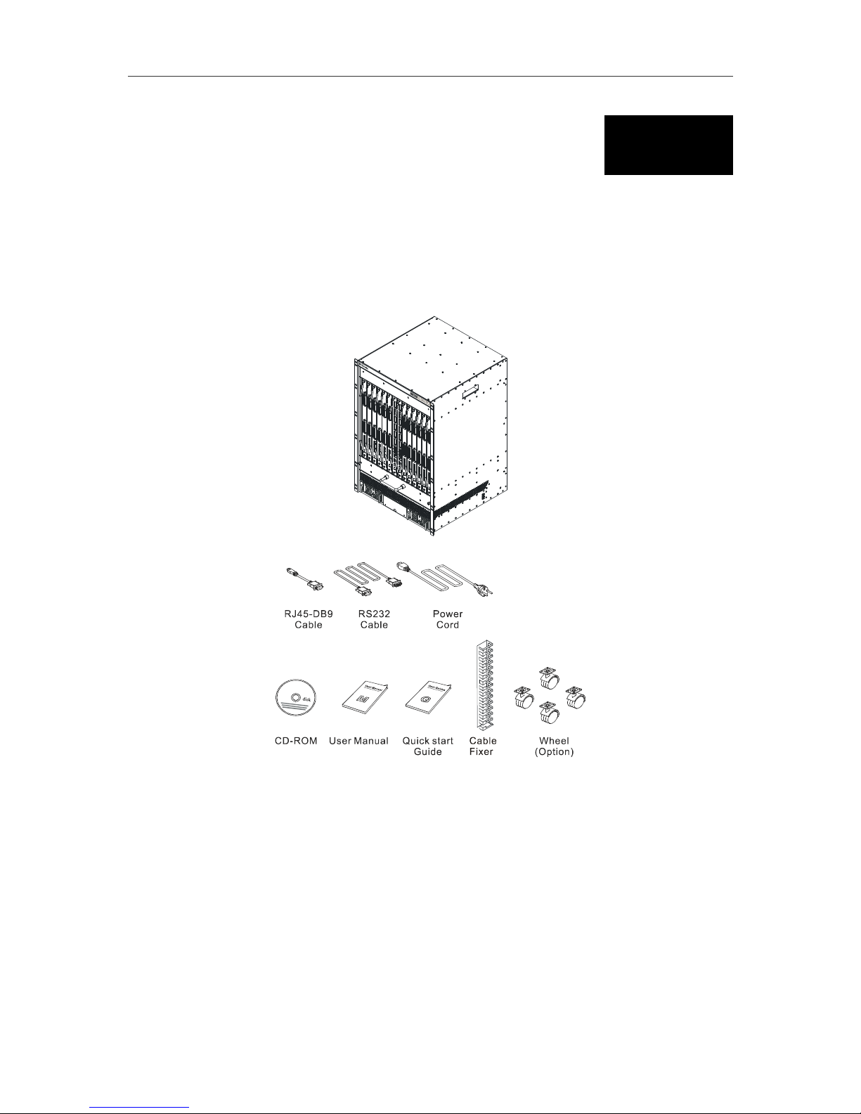
Open the shipping carton of the Switch and carefully unpack its contents. The carton should contain
the following items:
Figure 2 - 1. DES-7000 Switch chassis with shipped components
1. One switch chassis including:
§ One pre-installed DES-7003 CPU/uplink module
§ One pre-installed DES-7011 power supply unit
§ For DES-7000 chassis only - one pre-installed fan tray module with four fans
2. One cable bearer (DES-7000 only)
3. Four wheels (DES-7000 only)
4. One AC power cord
5. One RJ-45 to RS-232 9-pin (male) serial adapter
6. One CD-ROM containing documentation for the device
7. This printed Quick Installation Guide
If any item is found missing or damaged, please contact your local reseller for replacement.
DES-7000/DES-7100 Layer 2 Switch User’s Guide
Unpacking and Setup
10
Setup
The DES-7000 is shipped with the DES-7003 management module preinstalled. There are some
additional pieces that the user may opt to install. These are described below. The Quick Installation
Guide included with the switch contains illustrations and information that may be useful for installing
the additional hardware.
Make sure the location used is a suitable environment for the Switch and there is adequate ventilation.
Have the necessary cabling required to connect the Switch to the network.
You may install DES-7000 series network modules at any time before or after the switch has been
installed and powered on. Modules can be hot swapped to meet the changing demands of the network.
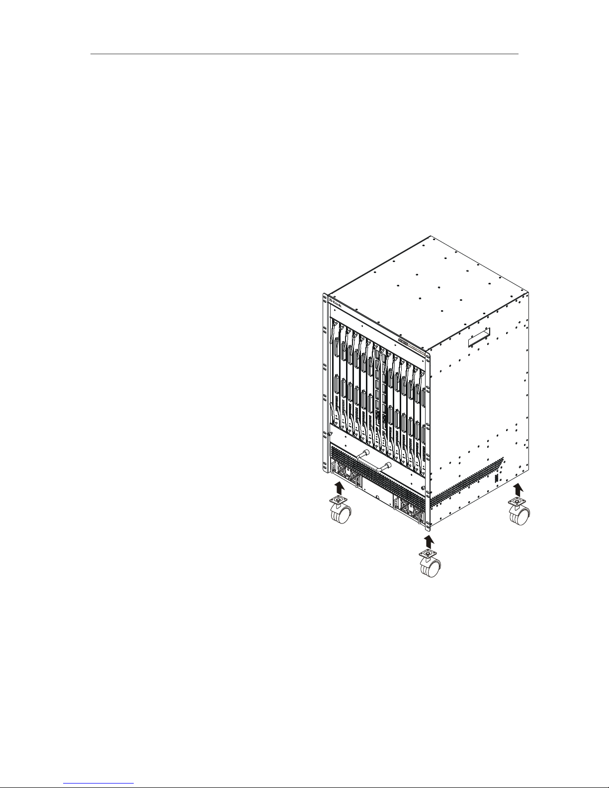
Attaching Wheels
The DES-7000 is shipped with four wheels that may
be install but are not required. To install the wheels,
gently place the chassis on either of its sides to
access the wheel mounts. Make sure the fan module
is firmly in place before tilting the chassis. Each
wheel is held in place with four screws (included in
the package with the wheels).
Rack Installation
The chassis may be placed into a standard 19”
equipment rack with or without the wheels attached.
The ears at the front of both sides of the chassis
should be used to hold it firmly in place with screws.
Figure 2 - 2. DES-7000 Switch Chassis with optional wheels
Cable Bearer
The cable bearer is attached to the top of the chassis front panel on the DES-7000 chassis. Use the
four screws included in the packaging.
DES-7000/DES-7100 Layer 2 Switch User’s Guide
Unpacking and Setup
11
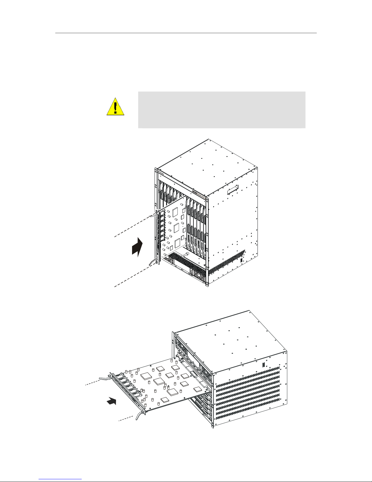
Installing Modules
The DES-7000 and DES-7100 Switch chassis’ has one DES-7003 management/uplink module
installed when shipped. In order to use other available modules you will need to install them. Follow
the instructions below. Modules can be installed into any free slot, except the CPU module.
WARNING
When handling Switch modules be sure to wear an ESD wrist
strap or suitable grounding device to prevent damage from
electrostatic discharge. Do not attach the strap to any part of the
power supply if the Switch is powered on.
Figure 2 - 3. Inserting a module into the DES-7000
Figure 2 - 4. Inserting a module into the DES-7100
DES-7000/DES-7100 Layer 2 Switch User’s Guide
Unpacking and Setup
12
To install a module, follow these steps:
WARNING
When using an ESD wrist strap or other grounding device, do not
attach it to any part of the power supply if the switch is powered
on.
1. Remove the faceplate from the slot intended for module insertion. Keep the faceplate in case it
is needed in the future.
2. Carefully remove the module from its packaging.
3. Line up the module with the grooved slot guides and insert it into the chassis. It should glide
easily toward the back of the chassis. Push it in until the module ejector levers are in contact
with the chassis. Be careful not to bend the circuit board of the module. Modules for the DES7000 should be oriented so the model number of the module is at the top and the LED
indicators are on the bottom. Modules installed in the DES-7100 should be inserted
horizontally in the upright position, that is, so the model number and LED indicator labels are
displayed so they can be read from left to right.
4. Push the ejector levers toward the center of the module until they touch the front of the module.
This will push the bus connectors into backplane of the chassis.
5. Hand-tighten the installation screws at each end of the module. The module is now firmly
seated in the backplane of the chassis.
Removing a Module
To remove a module from the chassis follow these steps:
WARNING
When using an ESD wrist strap or other grounding device, do not
attach it to any part of the power supply if the switch is powered
on.
1. Loosen the two installation screws on the front of the module.
2. Pull the ejector levers out and away from the center of the module front panel. This will pull the
module out of the backplane.
3. Cover the empty slot with a faceplate that was shipped with chassis.

DES-7000/DES-7100 Layer 2 Switch User’s Guide
Unpacking and Setup
13
Power on the Switch
The Switch is shipped with two DES-7011 RPS modules installed and is therefore ready to be
powered on after you have assembled the hardware. Follow these steps to power on the Switch:
1. Plug the device end of either power cord into either power supply.
2. Plug the outlet end of the power cord into a suitable AC power source.
3. Observe the LED indicators to make sure the Switch is functioning normally.
Upon powering on the LED indicators on the DES-7003 management/uplink module should operate as
follows:
§ All indicators will flash momentarily indicating a system reset.
§ The Power indicator will flash for a few seconds during the POST
§ The System Status LED indicator will be dark during CPU arbitration for several
seconds
The System Status and Power LED indicators will light steady green indicating normal system and
power supply function. An amber light in either of these indicates a problem.
Power Failure
As a precaution, the Switch should be unplugged in case of an impending power failure. When power
is resumed, plug the Switch back in.
Battery Back Up System
The DES-7000 and DES-7100 can be equipped with a battery back up system. Battery back ups may
only be installed by qualified technicians. Please contact your vendor for information on purchasing
and installing such a system.
DES-7000/DES-7100 Layer 2 Switch User’s Guide
Unpacking and Setup
14
Hot Swap Procedure for Switch Modules
All switch modules including the Primary Master and Primary Back Up CPU modules can be changed
while the Switch is powered on. Follow the procedures listed here to remove a module or to insert a
module while the Switch is powered on. Changing a module while the Switch is operating is commonly
called “hot swapping” which is the term we use in this document.
WARNING
When handing Switch modules be sure to wear an ESD wrist
strap to prevent damage from static electric discharge. Do not
attach the strap to any part of the power supply if the Switch is
powered on.
Hot Swap Removal of a Switch Module
Remove a single switch module following the procedure listed below. Only one module should be
removed at a time. Wait for the process to be completed before removing (or inserting) another
module. Wear an ESD wrist strap to prevent damage to the module from possible static electric
discharge.
To perform a hot swap removal of a switch module follow these steps:
1. Gently depress the Hot Swap button on the front panel of the module you want to remove.
The Hot Swap button is located between the Per Port Link LED indicators and the Power and
Hot Swap Status indicators. The button can be pressed using your finger, a ballpoint pen or
other suitable instrument.
2. Observe the Hot Swap & Card Status LED indicator on the switch module being removed. It
should blink amber. During this phase the module is sending a message to the master (CPU)
module that a removal has been initiated.
3. The master module detects the removal and updates its database. The master module cuts
power to the switch module being removed. The Power LED indicator and all other LED
indicators on the switch module will go dark.
4. When you see that the switch module has been powered off you may remove it. Unscrew the
installation screws and pull both ejector levers toward the center of the front panel of the
module to unseat it from the backplane of the Switch.
5. If the module is not being reinserted, completely remove it from the slot. It should slide out
easily in the guides. Be sure to properly store the module.
6. If you do not intend to install another module in the vacant slot, cover it with one of the slot
faceplates included with the original shipment.
Note
When performing a hot swap of a Master CPU module the
procedure is essentially the same as a hot swap of other switch
modules. The procedure for removing a Primary Master CPU
module is slightly different since the designation of Primary
Master must be transferred to the current Back Up Master before
the unit is powered off. This takes a few seconds. The Master
LED Indicator will light on the new Primary Master CPU module
indicating that the unit is the active master. The former Primary
Master module is powered off and may then be removed.
DES-7000/DES-7100 Layer 2 Switch User’s Guide
Unpacking and Setup
15
Hot Swap Insertion of a Switch Module
Follow the procedure listed below to insert a new switch module into an available slot while the Switch
is powered on. Only one module should be inserted at a time. Wait for the process to be completed
before inserting or removing another module. Wear an ESD wrist strap to prevent damage to the
module from possible static electric discharge.
1. If the slot is covered with a faceplate, remove and save it for later use.
2. Carefully remove the module from its packaging.
3. Line up the module with the grooved slot guides and insert it into the chassis. It should glide
easily toward the back of the chassis. Push it in until the module ejector levers are in contact
with the chassis. Be careful not to bend the circuit board of the module. Modules for the DES7000 should be oriented so the model number of the module is at the top and the LED
indicators are on the bottom.
4. Push the ejector levers toward the center of the module until they touch the front of the module.
This will push the bus connectors into backplane of the chassis.
5. Observe the Hot Swap & Card Status LED indicator on the switch module. This will blink
amber for about 13 seconds after being inserted. During this time the CPU is recognizing the
new switch module and the switch module is booting. A steady amber light indicates a system
failure.
6. A steady green Hot Swap & Card Status LED indicator on the switch module indicates the
module is ready and running normally. The master (CPU) module recognizes the new switch
module.
7. Hand-tighten the installation screws at each end of the module. The module is now firmly
seated in the chassis and powered on. This completes the hot swap insertion.
Hot Swap Procedure for Power Supply
DES-7011 RPS modules can be easily hot swapped. Follow the instructions below to replace a
redundant power supply.
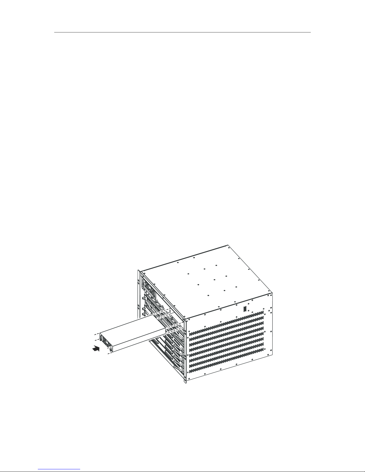
Inserting DES-7011 RPS Module into DES-7100 Chassis
DES-7000/DES-7100 Layer 2 Switch User’s Guide
Unpacking and Setup
16
To remove a DES-7011 RPS module:
1. Grasp the unit by the handles on the front using both hands.
2. Release the catch by applying upward pressure on the catch release near the left side of the
unit.
3. Pull the RPS unit straight out from the chassis.
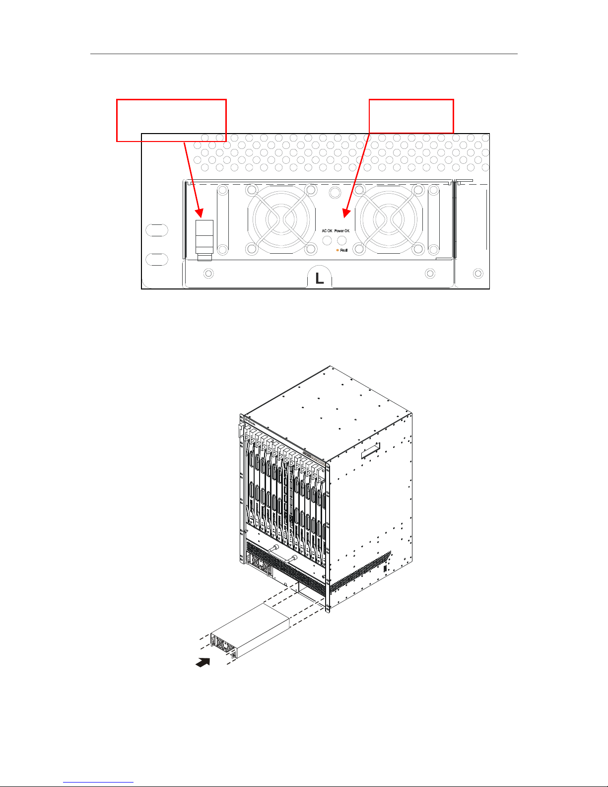
Inserting a DES-7011 RPS Module into the DES-7000 chassis
To insert an RPS module push the unit straight in toward the back of the chassis until the catch snaps
into place securely holding the RPS in position.
Pull up to release
RPS module
RPS status
LED indicators
DES-7000/DES-7100 Layer 2 Switch User’s Guide
Unpacking and Setup
17
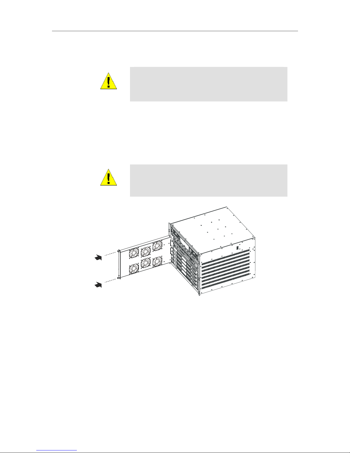
Hot Swap Procedure for Fan Tray Module
CAUTION
The Fan Tray Module can be replaced with the power on. If you
cannot replace the fan tray immediately (within two minutes) the
Switch chassis should be powered off to avoid damage from
overheating before the fan tray is removed.
Changing the fan tray module for the DES-7000 and DES-7100 is a simple procedure however if you
choose to do this while the Switch is powered on, be sure to have the replacement fan tray ready at
hand so the procedure can be completed as quickly as possible. It is not necessary to initiate the hot
swap procedure, the Master CPU will be aware of fan tray removal and insertion. Removal of the fan
tray will trigger the system alert buzzer and the Fan Fail LED indicator. Be sure to use proper ESD
grounding procedures to avoid electrostatic discharge. The procedure below describes this procedure
and changes to the LED indicators that occur.
WARNING
The fans will continue rotating for several seconds after power to
the unit is cut off. Use only the handle on the front of the fan tray
when removing the device to avoid risk of injury.
Inserting the fan tray into the DES-7100 chassis
To change the fan tray:
1. Unscrew the installation screws on each side of the module and pull the module from out of
the chassis. Be careful not to drop the fan tray when removing it.
2. Replace the fan tray module immediately if the Switch is powered on; insert the new unit using
the guides built into the chassis. It should glide easily into position if it is properly lined up.
3. Push the module toward the backplane of the chassis until the front of the module is flush with
the front panel of the chassis. You will need to apply firm pressure for about the last half
centimeter to establish the contacts and firmly position the unit in the backplane.
4. The fan tray will power on and be recognized by the Master CPU. You should see the Hot
Swap & Card Status LED indicator on the Master CPU module blink for about 13 seconds
while the unit is recognized.
Tighten the installation screws on the fan tray module. Observe the Fan/Fail LED indicator on the
Master CPU module to make sure it is functioning normally: dark for normal function, blinking amber if
there is a problem. The unit is now completely installed.
DES-7000/DES-7100 Layer 2 Switch User’s Guide
Identifying External Components
18
3
Identifying External Components
This chapter provides a description of the external hardware features for the DES-7000 and DES-7100
as well as the features of the DES-7000 Series Modules. Included are descriptions of the LED
indicators, ports and power supply.
Front Panel Views
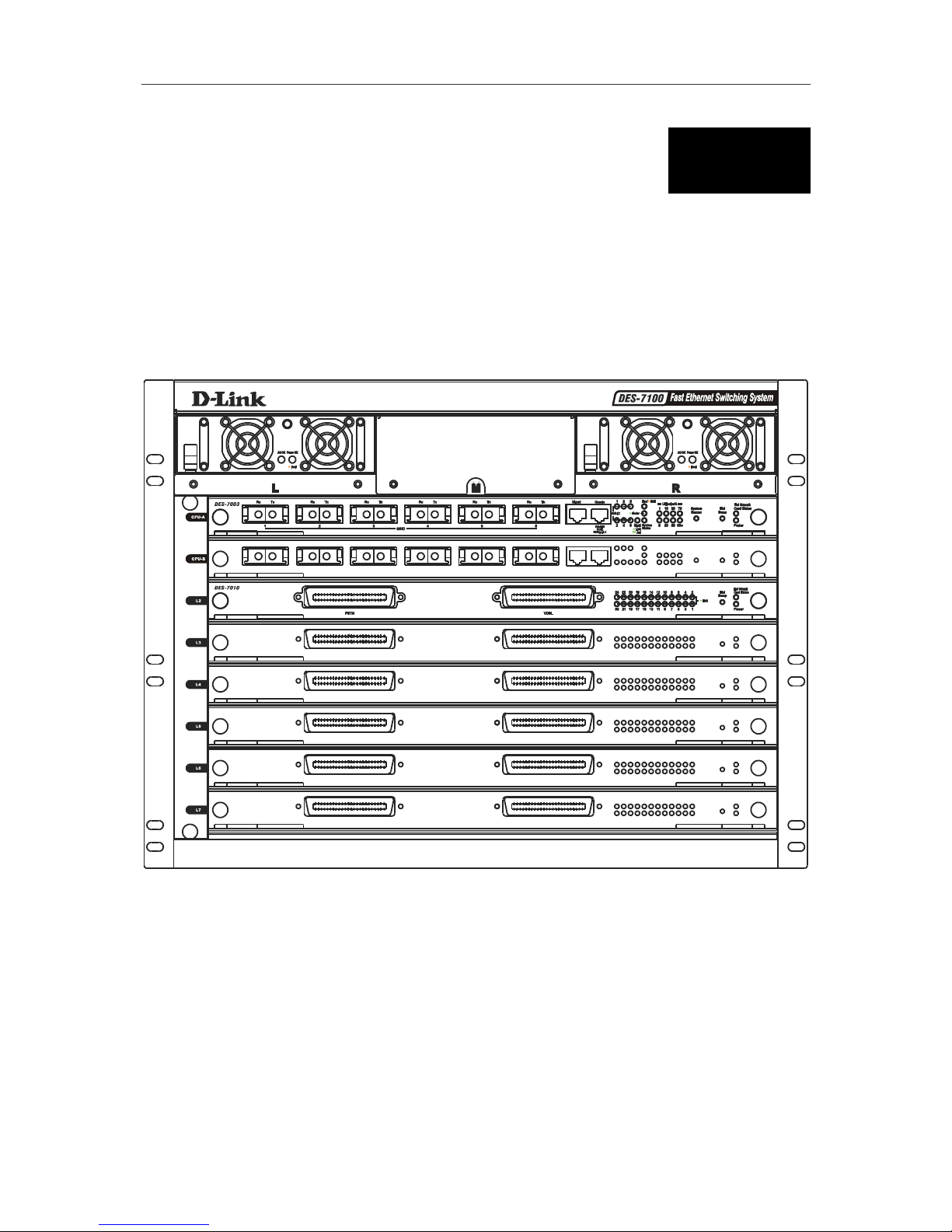
Figure 3-1. Front panel view of DES-7100 with DES-7010 Ethernet over VDSL Modules
The front panel of the DES-7100 features one installed redundant power supply. The remaining two
slots are available for additional RPS units. RPS slots are located along the top of the device and are
labeled L (left) M (middle) and R (right). Network module slots are labeled with the name of the slot
along the left side. The master CPU module is installed in the uppermost slot labeled CPU-A.
DES-7000/DES-7100 Layer 2 Switch User’s Guide
Identifying External Components
19
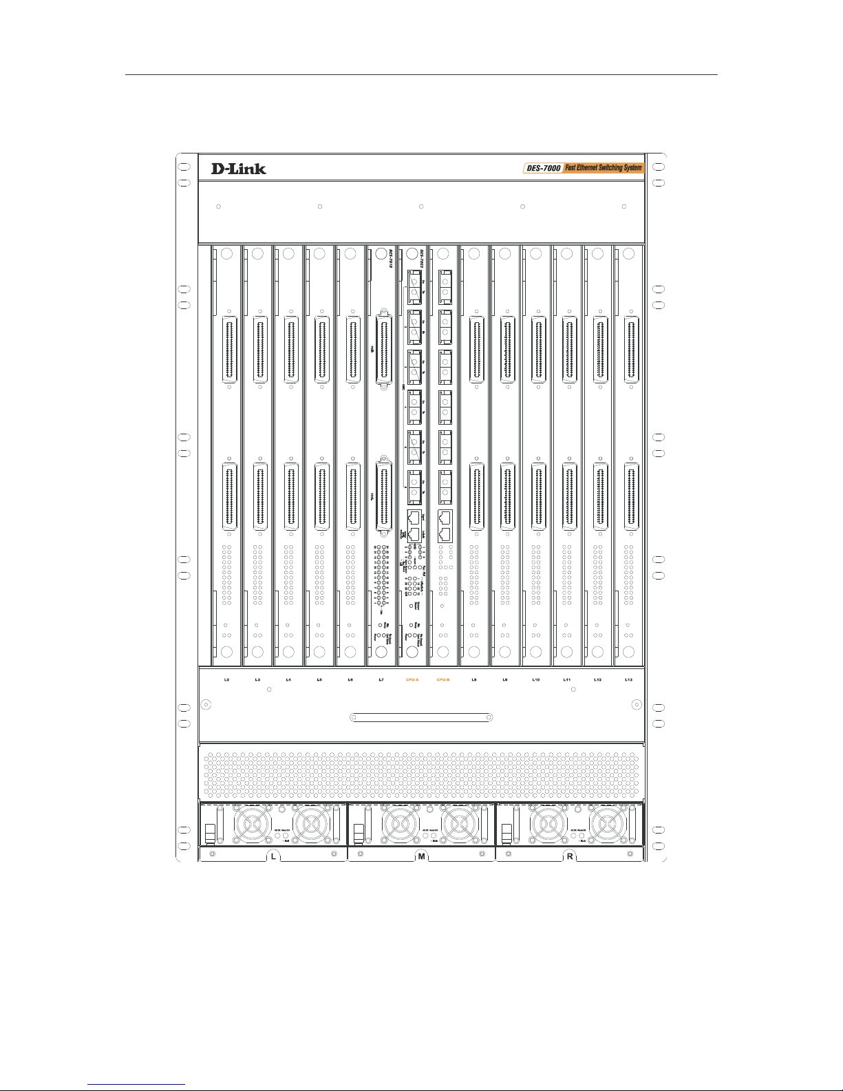
Figure 2 - 5. Front panel view of DES-7000 with DES-7010 Ethernet over VDSL Modules
The front panel of the DES-7000 features one installed redundant power supply. The remaining slots
are available for additional RPS units. RPS slots are located along the bottom of the device and are
labeled L (left) M (middle) and R (right). Network module slots are labeled with the name of the slot
along the top of the fan tray. The master CPU module is installed in the center slot labeled CPU-A.
DES-7000/DES-7100 Layer 2 Switch User’s Guide
Identifying External Components
20
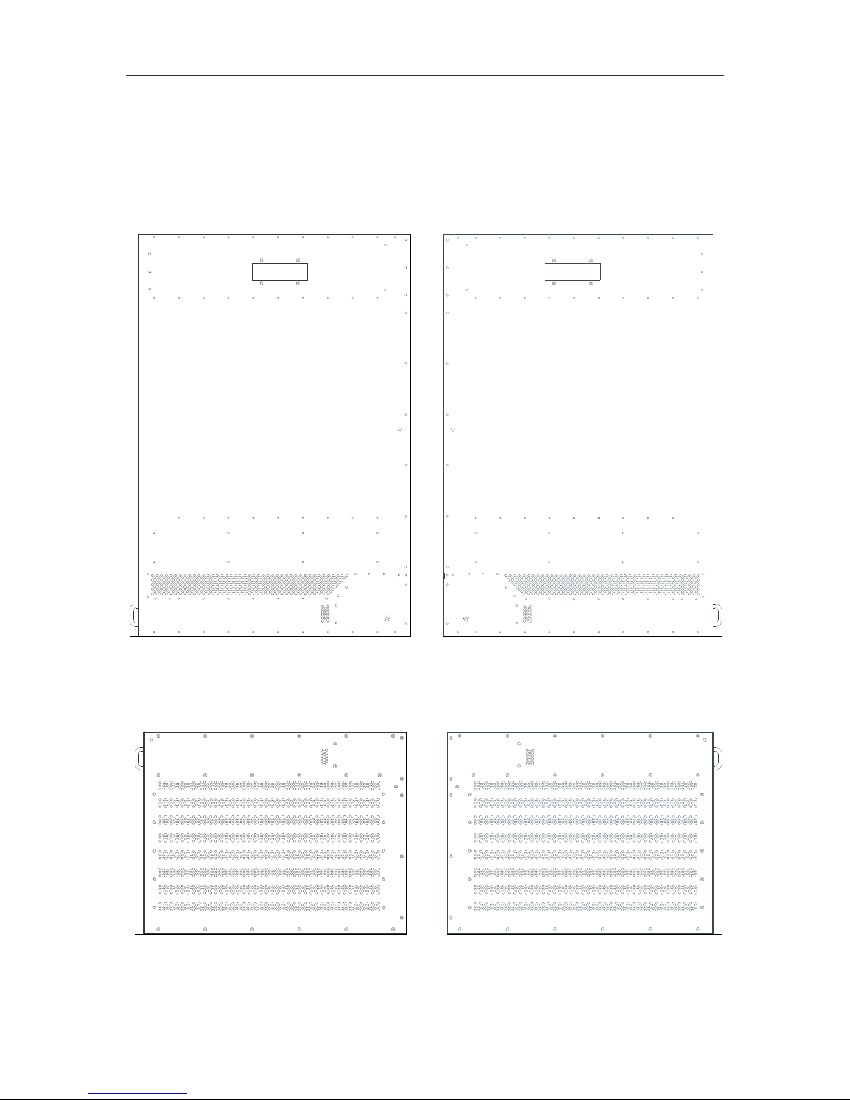
Side Panels
The DES-7000 and DES-7100 have vents to allow adequate airflow to the system fans. The system
fans are used to dissipate heat. Do not block these openings, and leave adequate space at the rear
and sides of the Switch for proper ventilation. Without proper heat dissipation and air circulation,
system components might overheat, which could lead to system failure.
Figure 3- 1. Right and Left Side Panel Views of the DES-7000
Figure 3- 2. Right and Left Side Panel View of the DES-7100
DES-7000/DES-7100 Layer 2 Switch User’s Guide
Identifying External Components
21
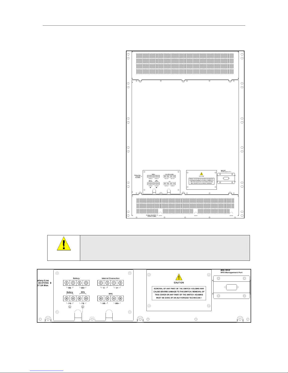
Rear Panel Views
Be sure to allow ample room at the
back of the Switch for proper ventilation.
Do not obstruct any vents on the Switch.
Please read and observe the cautionary
statement regarding removal of the
back panel.
The battery connection terminals are
used with battery back up systems.
These systems should be installed by a
qualified technician. Please contact
your vendor for information about
battery back up systems.
The RS-232 console port on the lower
right side of the rear panel is used with
DES-7012 RPS units only. The console
port is not used with DES-7011 RPS
units.
Figure 2 - 6. Rear panel of DES-7000
WARNING
Do not remove the panels covering the power supply or any other panel covering
the back of the Switch.
Figure 2 - 7. DES-7000 Battery Terminals and DES-7012 Management Console Port

DES-7000/DES-7100 Layer 2 Switch User’s Guide
Identifying External Components
22
Do not obstruct the vent
on the back panel or on
any part of the Switch.
Figure 2 - 8. Rear panel of DES-7100
WARNING
Do not remove the panels covering the power supply or any other panel covering
the back of the Switch.
Please read and observe the cautionary
statement regarding removal of the back
panel.
The battery connection terminals are used
with battery back up systems. These
systems should be installed by a qualified
technician. Please contact your vendor for
information about battery back up systems.
The RS-232 console port is used with DES7012 RPS units only. The console port is not
used with DES-7011 RPS units.
Figure 2 - 9. DES-7100 Battery Connection Terminals

DES-7000/DES-7100 Layer 2 Switch User’s Guide
Identifying External Components
23
Slot Numbering
Slot numbers on the chassis are labeled on the front panel of the fan tray modules for both the DES7000 and DES-7100. Each slot is given a Slot Name, Physical ID number and Logical ID number. Slot
numbering is permanent and absolute regardless of what type of module is installed. Management
modules may only be installed in the CPU slots. CPU slots for the DES-7000 are located in the
centermost slot positions and are labeled CPU-A and CPU-B. CPU slots for the DES-7100 are located
in the uppermost slot positions and are labeled CPU-A and CPU-B. Switch modules may be installed
in any of the remaining slots in any order regardless of the type of module. Refer to the tables in
Appendix B for Slot Name, Physical Slot ID and Logical Slot ID numbers.
Ports
DES-7003 CPU/Uplink Module
§ 1 RJ-45 Management Port (Mgmt) dedicated Switch management through Telnet or Webbased management
§ 1 RJ-45 Console Port for out-of-band management and system configuration (requires adapter
included with Switch)
§ 6 GBIC Gigabit Ethernet Ports for Uplinking Switch to network backbone
§ LED Indicators for monitoring status, system alerts and hot swapping
DES-7005 Ethernet/Fast Ethernet Module
§ 24 10BASE-T/100BASE-TX RJ-45 Ports
§ All ports support auto-polarity detection (MDI-X/MDI-II)
§ Connects to 10BASE-T and 100BASE-TX devices at full- or half-duplex
§ Supports Category 3, 4, 5 or better UTP or STP connections of up to 100 meters each
§ LED Indicators for per port link/activity and speed (above each port) plus hot swapping and
module status
DES-7006 100BASE-FX (SFF) Fast Ethernet Module
§ 24 100BASE-FX (SFF) Fast Ethernet ports
§ Connects to 100BASE-FX devices at full- or half-duplex
§ Fully compliant with IEEE 802.3u 100BASE-FX
§ IEEE 802.3x compliant Flow Control support for Full duplex
§ LED Indicators for link/activity (one above each port) plus hot swapping and module status
DES-7010 Ethernet over VDSL Module
§ 2 RJ-21 Ports for connection to 24 clients (ports)
§ Compliant with ETSI VDSL requirements
§ Supports symmetrical data transfer
§ LED Indicators for per port link status (grouped on right side of front panel) plus hot swapping
and module status
DES-7000/DES-7100 Layer 2 Switch User’s Guide
Identifying External Components
24
LED Indicators
The tables below list all the LED indicators for all switch modules and include illustrations of the
different LED indicators as they appear on the front panel. All switch modules, including CPU modules,
have LED indicators for Power and Hot Swap & Card Status useful when hot swapping the module.
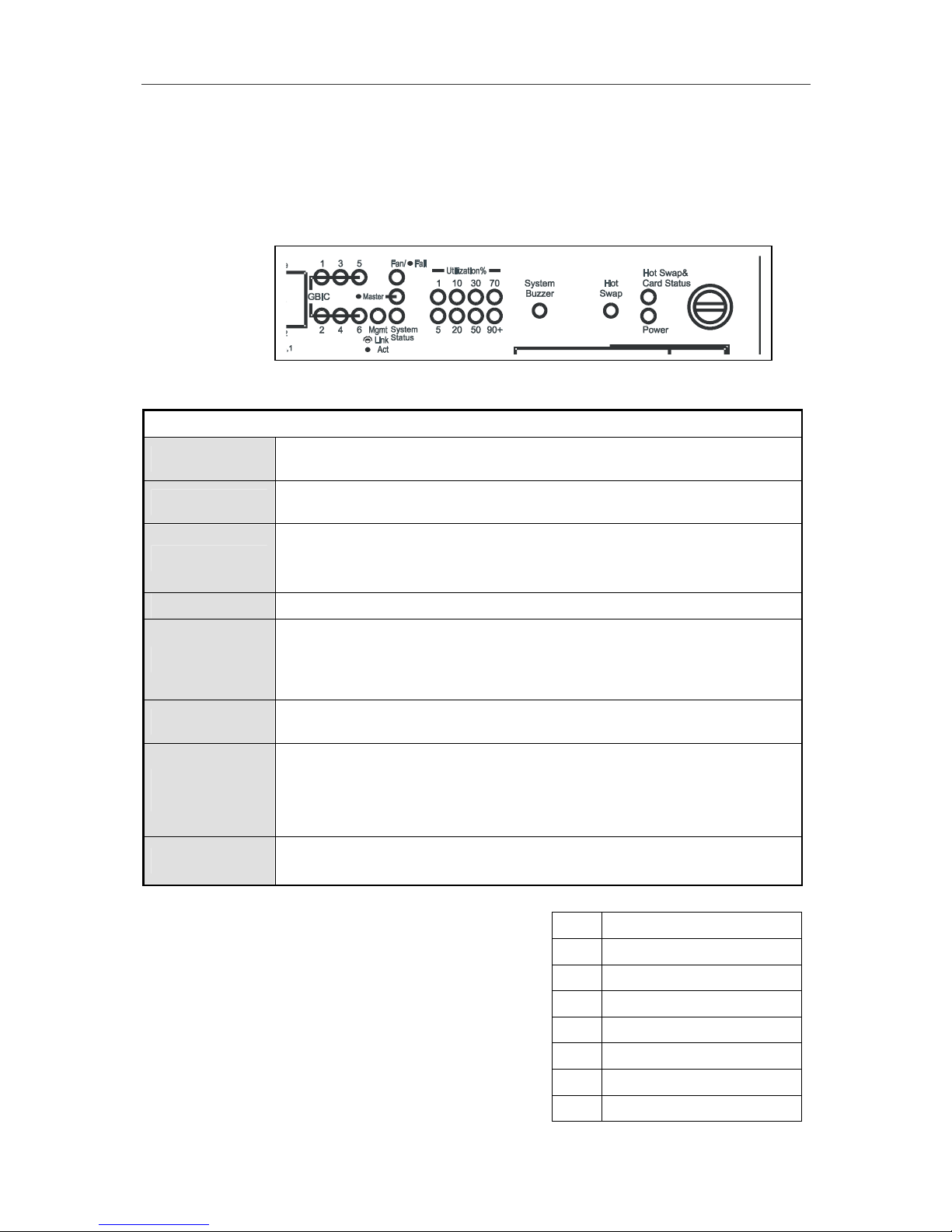
Figure 3-9. DES-7003 Module Front Panel LED Indicators
DES-7003 Management Module LED Indicators
Per Port GBIC
Lights green to indicate a link for the port. Blinks green when there is activity
on the port.
Mgmt
Lights steady green if there is a link on the Mgmt port. Blinks green when
there is activity on the port. Remains dark when there is no link.
Fan Fail*
Steady amber light indicates one or more fans not functioning.
This does not light when the fans are functioning normally.
A fan failure will also trigger the system buzzer (alarm).
Master
Lights steady green when module is performing as active primary master.
System Status
Steady green light indicates normal system function.
Amber light indicates abnormal function. Abnormal function can include RPS
failure, fan failure or temperature problem. Any of these problems will also
trigger an audible alarm, the system buzzer.
Utilization**
Eight scales are used, 1%, 5%, 10%, 20%, 30%, 50%, 70%, 90%+ to indicate
traffic rate to the CPU.
Hot Swap &
Card Status
This will begin to blink amber when a hot swap of the unit has been initiated. It
should begin blinking immediately after the Hot Swap button has been
pushed. After a few seconds the module will be powered off and it may be
safely removed. Please read the instructions for hot swap removal and
insertion of DES-7000 Series modules for a complete description.
Power
Steady green light indicates normal voltage status the module.
Amber light indicates a voltage problem in this module.
1% 1~200 packets per second
5% 201~400 packets per second
10% 401~600 packets per second
20% 601~800 packets per second
30% 801~1000 packets per second
50% 1001~1200 packets per second
80% 1201~1400 packets per second
90+% >1400 packets per second
*Please see the page 26
for more detailed
information about the system fans and the shutdown
sequence associated with fan failure.
**Utilization rates can be approximated to the number
of packets per second using th
e table to the right.
The indicators remain dark if there is no traffic.
DES-7000/DES-7100 Layer 2 Switch User’s Guide
Identifying External Components
25
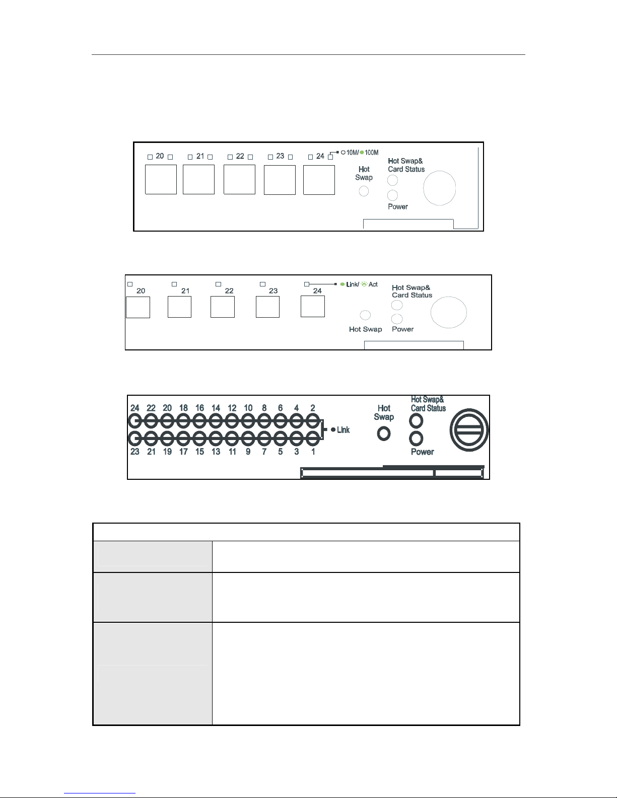
Switch Network Module LED Indicators
The different network modules for the Switch present different arrangements for the per port LED
indicators.
Figure 3- 3. DES-7005 LED Indicators
Figure 3- 4. DES-7006 LED Indicators
Figure 3- 5. DES-7-10 LED Indicators
Switch Module LED Indicators
Power
Steady green light indicates normal voltage status in this module.
Amber light indicates a voltage problem with this module.
Hot Swap & Card
Status
This will begin to blink amber when a hot swap of the unit has been
initiated. It should begin blinking immediately after the Hot Swap
button has been pushed. After a few seconds the module will be
powered off and it may be safely removed.
Per Port Indicators
Switch modules include per port LED indicators that differ for each
module.
The DES-7005 has one indicator per port for link/activity and another
per port indicator for speed above each port.
The DES-7006 has one per port indicator for link/activity above each
port.
The DES-7010 has per port indicators for link status on the right side
of the front panel.
DES-7000/DES-7100 Layer 2 Switch User’s Guide
Identifying External Components
26
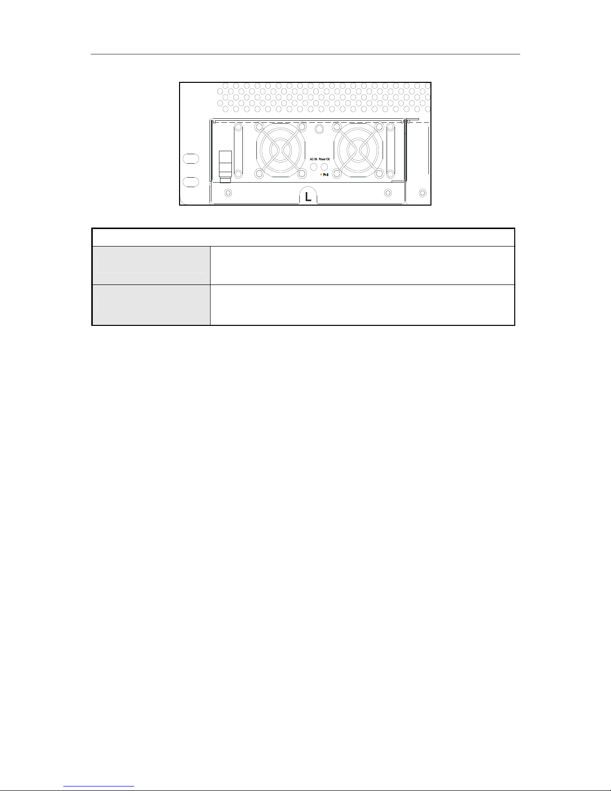
Figure 3- 6. Front Panel of DES-70011 RPS Unit and LED Indicators
LED Indicators for RPS Modules
AC OK
Steady green light indicates normal function.
A dark indicator means the unit is not receiving power or a problem
exists.
Power OK
Steady green light indicates normal output level.
Amber light indicates abnormal output level.
An RPS failure will also trigger the system buzzer (alarm).
AC Power Redundant Power Supplies
The chassis includes two pre-installed power supplies removable from the front with an additional RPS
slot available for a third module. The connector for each power supply is embedded on the rear panel.
The LED indicators for each power supply are located in the center of the front panel The LED
indicators will light green when the unit functioning normally. An amber LED indicator indicates the
RPS is not functioning properly.
Push Buttons
Two recessed push buttons are visible on the front panel of the DES-7003 CPU module a System
Buzzer and Hot Swap button. Each switch module, including DES-7003 CPU modules, has a Hot
Swap push button.
Push buttons are recessed to avoid accidental activation. They can be activated by gently depressing
them with a ballpoint pen or other suitable instrument. The functions activated by the buttons are
described as follows:
• System Buzzer (DES-7003 CPU modules only) A warning sounds when any system fans fail
or when the fan tray unit has been removed. Depressing the System Buzzer button will silence
the fan fail alarm.
Hot Swap This is used to initiate a hot swap of the module (See the section on hot swapping modules
below).
Fans
For the DES-7000 chassis, there are a total of 8 system fans arranged on two plains. At the top of the
backside of the Switch chassis are four fans (dimensions = 92 x 92 x 25 mm) arranged in a single
horizontal row spanning the width of the Switch. The upper fans run any time power is supplied to the
chassis. The remaining 4 fans (dimensions = 172 x 150 x 51 mm) are located in a separate slide-in fan
tray module oriented horizontally below the module slots. The fan tray fans are positioned to maintain
adequate airflow between installed switch modules. The fan tray fans are power on or off as needed
automatically by the CPU using temperature information from built-in sensors.
The DES-7100 has a fan tray module with 6 fans (dimensions = 80 x 80 x 20 mm) oriented vertically
on the right side of the switch chassis. The fan tray fans power on or off as needed automatically by
the CPU using temperature information from built-in sensors. Fan trays may be replaced from the front
of the chassis while the switch is powered on.

DES-7000/DES-7100 Layer 2 Switch User’s Guide
Identifying External Components
27
System fan failure can result in one or all modules being powered down. The shutdown sequence is as
follows:
□ If two fans fail, all slave modules and the backup Master will be powered off after 30 minutes if
not replaced.
□ If three fans fail, all slave modules and the backup Master will be powered off after 10 minutes.
□ If four fans fail, all slave modules and the backup Master will be powered off after 5 minutes.

DES-7000/DES-7100 Layer 2 Switch User’s Guide
Network Cabling and Connections
28
4
Network Cabling and Connections
This chapter describes cabling and connectors used to connect the module to a network and using the
LED indicators to evaluate network function.
Connect to the DES-7003 CPU Management/Uplink Module
The DES-7003 module has six Gigabit Ethernet port to uplink the Switch as well as two ports, a
Console port and an SNMP port, used for device management.
§ GBIC Uplink ports – Install 1000BASE-SX or 1000BASE-FX GBIC plug-in module. These
ports are used to link the Switch to the network backbone.
§ Console port – Use this for an out-of-band connection to manage the Switch. Connection
requires the RJ-45 to RS-232 serial adapter included with the Switch and an Ethernet cable.
Connect this directly to the serial port on a computer used for managing the Switch.
§ Mgmt port – This port is for out-of-band management of the Switch using either Telnet or web-
based management. The Switch can be connected directly to a computer with standard
Ethernet cable to the Ethernet port on a computer.
Connect to the DES-7005 10BASE-T/100BASE-TX Module
Network connections to the 24 ports of the Ethernet module are made using Category 5 or better
cabling with RJ-45 UTP connectors. Ports may be connected to network devices that support
10BAES-T or 100BASE-TX operation. All ports support auto-negotiation by default for speed, duplex
and flow control (in Full duplex mode). All ports are configurable to force different speed, duplex and
flow control operation. All ports supports auto-detection of polarity and adjust for MDI/MDI-X
connectors to establish a valid link.
The per port LED Link indicators on the DES-7005 will:
§ Light green when a link has been established
§ Blink green when there is activity in the port
§ Remain dark when there is no link
Connect to the DES-7006 100BASE-FX Module
Network connections to the 24 ports of the 100BASE-FX module are made using single multimode
fiber (SMF/MMF) optic cabling with SFF (LC Duplex) type connectors.
The per port LED Link indicators on the DES-7006 will:
§ Light green when a link has been established
§ Blink green when there is activity in the port
§ Remain dark when there is no link
 Loading...