

Page 1

DES-3624 Series
Stackable NWay Ethernet Switch
User’s Guide
Fifth Edition (December 2001)
651S3624.055
Printed In Taiwan
RECYCLABLE
Page 2

Wichtige Sicherheitshinweise
1. Bitte lesen Sie sich diese Hinweise sorgfältig durch.
2. Heben Sie diese Anleitung für den spätern Gebrauch auf.
3. Vor jedem Reinigen ist das Gerät vom Stromnetz zu trennen. Vervenden Sie keine Flüssig- oder Aerosolreiniger. Am besten dient ein angefeuchtetes
Tuch zur Reinigung.
4. Um eine Beschädigung des Gerätes zu vermeiden sollten Sie nur Zubehörteile verwenden, die vom Hersteller zugelassen sind.
5. Das Gerät is vor Feuchtigkeit zu schützen.
6. Bei der Aufstellung des Gerätes ist auf sichern Stand zu achten. Ein Kippen oder Fallen könnte Verletzungen hervorrufen. Verwenden Sie nur sichere
Standorte und beachten Sie die Aufstellhinweise des Herstellers.
7. Die Belüftungsöffnungen dienen zur Luftzirkulation die das Gerät vor Überhitzung schützt. Sorgen Sie dafür, daß diese Öffnungen nicht abgedeckt
werden.
8. Beachten Sie beim Anschluß an das Stromnetz die Anschlußwerte.
9. Die Netzanschlußsteckdose muß aus Gründen der elektrischen Sicherheit einen Schutzleiterkontakt haben.
10. Verlegen Sie die Netzanschlußleitung so, daß niemand darüber fallen kann. Es sollete auch nichts auf der Leitung abgestellt werden.
11. Alle Hinweise und Warnungen die sich am Geräten befinden sind zu beachten.
12. Wird das Gerät über einen längeren Zeitraum nicht benutzt, sollten Sie es vom Stromnetz trennen. Somit wird im Falle einer Überspannung eine
Beschädigung vermieden.
13. Durch die Lüftungsöffnungen dürfen niemals Gegenstände oder Flüssigkeiten in das Gerät gelangen. Dies könnte einen Brand bzw. Elektrischen Schlag
auslösen.
14. Öffnen Sie niemals das Gerät. Das Gerät darf aus Gründen der elektrischen Sicherheit nur von authorisiertem Servicepersonal geöffnet werden.
15. Wenn folgende Situationen auftreten ist das Gerät vom Stromnetz zu trennen und von einer qualifizierten Servicestelle zu überprüfen:
a – Netzkabel oder Netzstecker sint beschädigt.
b – Flüssigkeit ist in das Gerät eingedrungen.
c – Das Gerät war Feuchtigkeit ausgesetzt.
d – Wenn das Gerät nicht der Bedienungsanleitung ensprechend funktioniert oder Sie mit Hilfe dieser Anleitung keine Verbesserung erzielen.
e – Das Gerät ist gefallen und/oder das Gehäuse ist beschädigt.
f – Wenn das Gerät deutliche Anzeichen eines Defektes aufweist.
16. Bei Reparaturen dürfen nur Orginalersatzteile bzw. den Orginalteilen entsprechende Teile verwendet werden. Der Einsatz von ungeeigneten
Ersatzteilen kann eine weitere Beschädigung hervorrufen.
17. Wenden Sie sich mit allen Fragen die Service und Repartur betreffen an Ihren Servicepartner. Somit stellen Sie die Betriebssicherheit des Gerätes
sicher.
18. Zum Netzanschluß dieses Gerätes ist eine geprüfte Leitung zu verwenden, Für einen Ne nnstrom bis 6A und einem Gerätegewicht grßer 3kg ist eine
Leitung nicht leichter als H05VV-F, 3G, 0.75mm2 einzusetzen.
Page 3

WARRANTIES EXCLUSIVE
IF THE D-LINK PRODUCT DOES NOT OPERATE AS WARRANTED ABOVE, THE CUSTOMER'S SOLE REMEDY SHALL BE, AT D-LINK'S OPTION,
REPAIR OR REPLACEMENT. THE FOREGOING WARRANTIES AND REMEDIES ARE EXCLUSIVE AND ARE IN LIEU OF ALL OTHER WARRANTIES,
EXPRESSED OR IMPLIED, EITHER IN FACT OR BY OPERATION OF LAW, STATUTORY OR OTHERWISE, INCLUDING WARRANTIES OF
MERCHANTABILITY AND FITNESS FOR A PARTICULAR PURPOSE. D-LINK NEITHER ASSUMES NOR AUTHORIZES ANY OTHER PERSON TO
ASSUME FOR IT ANY OTHER LIABILITY IN CONNECTION WITH THE SALE, INSTALLATION MAINTENANCE OR USE OF D-LINK'S PRODUCTS
D-LINK SHALL NOT BE LIABLE UNDER THIS WARRANTY IF ITS TESTING AND EXAMINATION DISCLOSE THAT THE ALLEGED DEFECT IN THE
PRODUCT DOES NOT EXIST OR WAS CAUSED BY THE CUSTOMER'S OR ANY THIRD PERSON'S MISUSE, NEGLECT, IMPROPER INSTALLATION OR
TESTING, UNAUTHORIZED ATTEMPTS TO REPAIR, OR ANY OTHER CAUSE BEYOND THE RANGE OF THE INTENDED USE, OR BY ACCIDENT,
FIRE, LIGHTNING OR OTHER HAZARD.
LIMITATION OF LIABILITY
IN NO EVENT WILL D-LINK BE LIABLE FOR ANY DAMAGES, INCLUDING LOSS OF DATA, LOSS OF PROFITS, COST OF COVER OR OTHER
INCIDENTAL, CONSEQUENTIAL OR INDIRECT DAMAGES ARISING OUT THE INSTALLATION, MAINTENANCE, USE, PERFORMANCE, FAILURE OR
INTERRUPTION OF A D- LINK PRODUCT, HOWEVER CAUSED AND ON ANY THEORY OF LIABILITY. THIS LIMITATION WILL APPLY EVEN IF DLINK HAS BEEN ADVISED OF THE POSSIBILITY OF SUCH DAMAGE.
IF YOU PURCHASED A D-LINK PRODUCT IN THE UNITED STATES, SOME STATES DO NOT ALLOW THE LIMITATION OR EXCLUSION OF
LIABILITY FOR INCIDENTAL OR CONSEQUENTIAL DAMAGES, SO THE ABOVE LIMITATION MAY NOT APPLY TO YOU.
Page 4

Limited Warranty
Hardware:
D-Link warrants each of its hardware products to be free from defects in workmanship and materials under normal use and service for a period commencing
on the date of purchase from D-Link or its Authorized Reseller and extending for the length of time stipulated by the Authorized Reseller or D-Link Branch
Office nearest to the place of purchase.
This Warranty applies on the condition that the product Registration Card is filled out and returned to a D-Link office within ninety (90) days of purchase. A
list of D-Link offices is provided at the back of this manual, together with a copy of the Registration Card.
If the product proves defective within the applicable warranty period, D-Link will provide repair or replacement of the product. D-Link shall have the sole
discretion whether to repair or replace, and replacement product may be new or reconditioned. Replacement product shall be of equivalent or better
specifications, relative to the defective product, but need not be identical. Any product or part repaired by D-Link pursuant to this warranty shall have a
warranty period of not less than 90 days, from date of such repair, irrespective of any earlier expiration of original warranty period. When D-Link provides
replacement, then the defective product becomes the property of D-Link.
Warranty service may be obtained by contacting a D-Link office within the applicable warranty period, and requesting a Return Material Authorization (RMA)
number. If a Registration Card for the product in question has not been returned to D-Link, then a proof of purchase (such as a copy of the dated purchase
invoice) must be provided. If Purchaser's circumstances require special handling of warranty correction, then at the time of requesting RMA number,
Purchaser may also propose special procedure as may be suitable to the case.
After an RMA number is issued, the defective product must be packaged securely in the original or other suitable shipping package to ensure that it will not
be damaged in transit, and the RMA number must be prominently marked on the outside of the package. The package must be mailed or otherwise shipped
to D-Link with all costs of mailing/shipping/insurance prepaid. D-Link shall never be responsible for any software, firmware, information, or memory data of
Purchaser contained in, stored on, or integrated with any product returned to D-Link pursuant to this warranty.
Any package returned to D-Link without an RMA number will be rejected and shipped back to Purchaser at Purchaser's expense, and D-Link reserves the right
in such a case to levy a reasonable handling charge in addition mailing or shipping costs.
Software:
Warranty service for software products may be obtained by contacting a D-Link office within the applicable warranty period. A list of D-Link offices is
provided at the back of this manual, together with a copy of the Registration Card. If a Registration Card for the product in question has not been returned
to a D-Link office, then a proof of purchase (such as a copy of the dated purchase invoice) must be provided when requesting warranty service. The term
"purchase" in this software warranty refers to the purchase transaction and resulting license to use such software.
D-Link warrants that its software products will perform in substantial conformance with the applicable product documentation provided by D-Link with such
software product, for a period of ninety (90) days from the date of purchase from D-Link or its Authorized Reseller. D-Link warrants the magnetic media, on
which D-Link provides its software product, against failure during the same warranty period. This warranty applies to purchased software, and to
replacement software provided by D-Link pursuant to this warranty, but shall not apply to any update or replacement which may be provided for download
via the Interne t, or to any update which may otherwise be provided free of charge.
D-Link's sole obligation under this software warranty shall be to replace any defective software product with product which substantially conforms to D-Link's
applicable product documentat ion. Purchaser assumes responsibility for the selection of appropriate application and system/platform software and associated
reference materials. D-Link makes no warranty that its software products will work in combination with any hardware, or any application or
system/platform software product provided by any third party, excepting only such products as are expressly represented, in D-Link's applicable product
documentation as being compatible. D-Link's obligation under this warranty shall be a reaso nable effort to provide compatibility, but D-Link shall have no
obligation to provide compatibility when there is fault in the third-party hardware or software. D-Link makes no warranty that operation of its software
products will be uninterrupted or abso lutely error-free, and no warranty that all defects in the software product, within or without the scope of D-Link's
applicable product documentation, will be corrected.
D-Link Offices for Registration and Warranty Service
The product's Registration Card, provided at the back of this manual, must be sent to a D-Link office. To obtain an RMA number for warranty service as to a
hardware product, or to obtain warranty service as to a software product, contact the D-Link office nearest you. An address/telepho ne/fax/e-mail/Web site
list of D-Link offices is provided in the back of this manual.
Trademarks
Copyright 2001 D-Link Corporation.
Contents subject to change without prior notice.
D-Link is a registered trademark of D-Link Corporation/D-Link Systems, Inc. All other trademarks belong to their
respective proprietors.
Copyright Statement
Page 5

No part of this publication may be reproduced in any form or by any means or used to make any derivative such as
translation, transformation, or adaptation without permission from D-Link Corporation/D-Link Systems Inc., as
stipulated by the United States Copyright Act of 1976.
FCC Warning
This equipment has been tested and found to comply with the limits for a Class A digital device, pursuant to Part 15 of the
FCC Rules. These limits are designed to provide reasonable protection against harmful interference when the equipment
is operated in a commercial environment. This equipment generates, uses, and can radiate radio frequency energy and, if
not installed and used in accordance with this user’s guide, may cause harmful interference to radio communications.
Operation of this equipment in a residential area is likely to cause harmful interference in which case the user will be
required to correct the interference at his own expense.
This device complies with part 15 of the FCC Rules. Operation is subject to the following two conditions: (1) This device
may not cause harmful interference, and (2) this device must accept any interference received, including interference that
may cause undesired operation.
CE Mark Warning
This is a Class A product. In a domestic environment, this product may cause radio interference in which case the user may
be required to take adequate measures.
Warnung!
Dies ist in Produkt der Klasse A. Im Wohnb ereich kann dieses Produkt Funkstoerungen verursachen. In diesem Fall kann
vom Benutzer verlangt werden, angemessene Massnahmen zu ergreifen.
Precaución!
Este es un producto de Clase A. En un entorno doméstico, puede causar interferencias de radio, en cuyo case, puede
requerirse al usuario para que adopte las medidas adecuadas.
Attention!
Ceci est un produit de classe A. Dans un environnement domestique, ce produit pourrait causer des interférences radio,
auquel cas l`utilisateur devrait prendre les mesures adéquates.
Attenzione!
Il presente prodotto appartiene alla classe A. Se utilizzato in ambiente domestico il prodotto può causare interferenze
radio, nel cui caso è possibile che l`utente debba assumere provvedimenti adeguati.
VCCI Warning
BSMI Warning
Page 6

TABLE OF C ONTENTS
0 ABOUT THIS GUIDE................................................................................................................................................................................10
CONVENTIONS................................................................................................................................................................................................10
OVERVIEW OF THIS USER ’S GUIDE ............................................................................................................................................................. 10
1 INTRODUCTION......................................................................................................................................................................................11
FAST ETHERNET TECHNOLOGY .................................................................................................................................................................11
G IGABIT ETHERNET TECHNOLOGY ........................................................................................................................................................... 11
SWITCHING TECHNOLOGY ..........................................................................................................................................................................12
FEATURES.......................................................................................................................................................................................................12
Ports .............................................................................................................................................................................................................12
Performance features................................................................................................................................................................................13
Management ...............................................................................................................................................................................................13
2 UNPACKING AND SETUP......................................................................................................................................................................14
UNPACKING....................................................................................................................................................................................................14
SETUP .............................................................................................................................................................................................................. 14
DESKTOP OR SHELF INSTALLAT ION ......................................................................................................................................................... 14
RACK INSTALLATION ................................................................................................................................................................................... 15
POWER ON ...................................................................................................................................................................................................... 16
Power Failure............................................................................................................................................................................................16
3 IDENTIFYING EXTERNAL COMPONENTS.......................................................................................................................................17
FRONT PANEL ................................................................................................................................................................................................ 17
REAR PANEL...................................................................................................................................................................................................18
SIDE PANELS .................................................................................................................................................................................................. 18
STACK OPERATION......................................................................................................................................................................................19
OPTIONAL PLUG-IN MODULES...................................................................................................................................................................20
100BASE-FX (MT-RJ) Module...............................................................................................................................................................21
100BASE-FX (SC) Module......................................................................................................................................................................21
100BASE-TX Module................................................................................................................................................................................22
1000BASE-SX Gigabit Module...............................................................................................................................................................22
1000BASE-LX Gigabit Module...............................................................................................................................................................23
1000BASE-T Copper Gigabit Module...................................................................................................................................................23
LED INDICATORS...........................................................................................................................................................................................24
4 CONNECTING THE SWITCH................................................................................................................................................................26
SWITCH TO END NODE................................................................................................................................................................................26
SWITCH TO HUB OR SWITCH......................................................................................................................................................................26
10BASE-T Device.......................................................................................................................................................................................27
100BASE-TX Device..................................................................................................................................................................................27
5 SWITCH MANAGEMENT CONCEPTS ...............................................................................................................................................28
LOCAL CONSOLE MANAGEMENT...............................................................................................................................................................28
Diagnostic (Console) Port (RS-232 DCE)...........................................................................................................................................28
IP ADDRESSES AND SNMP COMMUNITY NAMES....................................................................................................................................29
TRAPS..............................................................................................................................................................................................................29
MIBS................................................................................................................................................................................................................30
PACKET FORWARDING.................................................................................................................................................................................30
Page 7

Aging Time..................................................................................................................................................................................................30
Filtering Database....................................................................................................................................................................................31
SPANNING TREE ALGORITHM....................................................................................................................................................................31
STA Operation Levels...............................................................................................................................................................................31
On the Bridge Level................................................................................................................................................................................31
On the Port Level....................................................................................................................................................................................32
User-Changeable STA Parameters.........................................................................................................................................................32
Illustration of STA.....................................................................................................................................................................................33
PORT TRUNKING............................................................................................................................................................................................34
VLAN S & MAC-BASED BROADCAST DOMAINS.......................................................................................................................................35
MAC-Based Broadcast Domains............................................................................................................................................................36
IEEE 802.1Q VLANs..................................................................................................................................................................................36
802.1Q VLAN Segmentation.................................................................................................................................................................36
Sharing Resources Across 802.1Q VLANs ........................................................................................................................................37
802.1Q VLANs Spanning Multiple Switches......................................................................................................................................37
VLANs Over 802.1Q -compliant Switches...................................................................................................................................... 38
Port-Based VLANs.....................................................................................................................................................................................39
BROADCAST STORMS....................................................................................................................................................................................39
Segmenting Broadcast Domains .............................................................................................................................................................40
Eliminating Broadcast Storms................................................................................................................................................................40
6 USING THE CONSOLE I NTERFACE....................................................................................................................................................41
SETTING UP A CONSOLE.............................................................................................................................................................................41
CONNECTING TO THE SWITCH USING TELNET ....................................................................................................................................... 42
CONSOLE USAGE CONVENTIONS.................................................................................................................................................................42
FIRST TIME CONNECTING TO THE SWITCH.............................................................................................................................................42
User Accounts Management....................................................................................................................................................................44
Save Changes.............................................................................................................................................................................................45
LOGIN ON THE SWITCH CONSOLE BY REGISTERED USERS...................................................................................................................45
Create/Modify User Accounts.............................................................................................................................................................45
User Accounts Control Table...............................................................................................................................................................47
SETTING UP THE SWITCH...........................................................................................................................................................................48
System Configuration...............................................................................................................................................................................48
Configure IP Address............................................................................................................................................................................48
Configure Console..................................................................................................................................................................................49
Configure Switch Stack..........................................................................................................................................................................50
Information of Individual Switch Unit..............................................................................................................................................51
Advance Settings................................................................................................................................................................................52
Configure Port.........................................................................................................................................................................................53
Configure Trunk Groups........................................................................................................................................................................55
Configure Port Mirroring.......................................................................................................................................................................56
Configure Spanning Tree Protocol......................................................................................................................................................57
STP Parameter Settings....................................................................................................................................................................57
STP Custom Settings.........................................................................................................................................................................60
Configure Filtering and Forwarding Table..........................................................................................................................................61
Configure Static Forwarding Table.................................................................................................................................................62
Configure MAC Address Filtering....................................................................................................................................................63
Configure Static Multicast Filtering..................................................................................................................................................63
Configure IGMP ..................................................................................................................................................................................64
Configure VLANs & MAC-based Broadcast Domains....................................................................................................................67
Configure MAC-based Broadcast Domains..................................................................................................................................68
Configure Port-based VLANs..........................................................................................................................................................71
Configure 802.1Q VLANs.................................................................................................................................................................74
Configure GMRP.................................................................................................................................................................................79
Update Firmware and Configuration Files..........................................................................................................................................83
Special Note Concerning Firmware Updates......................................................................................................................................84
System Utilities...........................................................................................................................................................................................85
Page 8

Ping Test..................................................................................................................................................................................................85
Save Settings to TFTP Server...............................................................................................................................................................86
Save Switch History to TFTP Server...................................................................................................................................................87
Clear Address Table...............................................................................................................................................................................88
Community Strings and Trap Stations..................................................................................................................................................88
SWITCH MONITORING ................................................................................................................................................................................. 89
Network Monitoring.................................................................................................................................................................................89
Traffic Statistics......................................................................................................................................................................................90
Port Utilization.....................................................................................................................................................................................91
Port Traffic Statistics...........................................................................................................................................................................92
Port Packet Error Statistics...............................................................................................................................................................93
Port Packet Analysis Statistics.........................................................................................................................................................94
Browse Address Table ..........................................................................................................................................................................95
Switch History.........................................................................................................................................................................................96
Browse IGMP Status..............................................................................................................................................................................96
Browse GVRP Status..............................................................................................................................................................................97
Browse GMRP Status.............................................................................................................................................................................98
RESETTING THE SWITCH.............................................................................................................................................................................99
Restart System ............................................................................................................................................................................................99
Factory Reset...........................................................................................................................................................................................100
Logout.......................................................................................................................................................................................................101
7 WEB-BASED NETWORK M ANAGEMENT.....................................................................................................................................102
INTRODUCTION...........................................................................................................................................................................................102
G ETTING STARTED..................................................................................................................................................................................... 102
MANAGEMENT ............................................................................................................................................................................................102
Configuration..........................................................................................................................................................................................103
IP Address.............................................................................................................................................................................................103
Switch Module......................................................................................................................................................................................104
Switch Module Information.............................................................................................................................................................105
Advanced Settings...............................................................................................................................................................................106
Port .......................................................................................................................................................................................................... 107
Trunk Groups........................................................................................................................................................................................109
Port Mirroring........................................................................................................................................................................................110
Spanning Tree Protocol.......................................................................................................................................................................110
STP Switch Settings.........................................................................................................................................................................111
STP Port Settings..............................................................................................................................................................................112
Forwarding and Filtering.....................................................................................................................................................................112
Static Forwarding Table..................................................................................................................................................................114
MAC Address Filtering Table.........................................................................................................................................................116
Static Multicast Filtering...................................................................................................................................................................118
IGMP.......................................................................................................................................................................................................119
IGMP Settings....................................................................................................................................................................................120
802.1Q IGMP.....................................................................................................................................................................................121
VLANs .................................................................................................................................................................................................... 124
MAC-Based Broadcast Domains...................................................................................................................................................125
Port-based VLANs...........................................................................................................................................................................130
802.1Q VLANs..................................................................................................................................................................................132
GMRP..................................................................................................................................................................................................136
Management ............................................................................................................................................................................................ 140
Community Strings and Trap Receivers............................................................................................................................................141
User Accounts Management..............................................................................................................................................................142
Console ..................................................................................................................................................................................................144
Monitoring...............................................................................................................................................................................................144
Switch Overview...................................................................................................................................................................................145
Port Utilization.......................................................................................................................................................................................146
Port Traffic Statistics............................................................................................................................................................................147
Page 9

Port Error Packet Statistics..................................................................................................................................................................148
Port Packet Analysis Statistics...........................................................................................................................................................149
Browse Address Table ........................................................................................................................................................................151
IP Multicast & IGMP Information......................................................................................................................................................152
Browse GVRP Status............................................................................................................................................................................153
Browse GMRP Status...........................................................................................................................................................................154
Switch History.......................................................................................................................................................................................155
Maintenance............................................................................................................................................................................................155
Firmware and Configuration Update..................................................................................................................................................156
Save Settings To TFTP Server...........................................................................................................................................................157
Save Switch History To TFTP Server................................................................................................................................................158
Clear Address Table.............................................................................................................................................................................159
Save Changes........................................................................................................................................................................................160
Factory Reset........................................................................................................................................................................................161
Restart System......................................................................................................................................................................................162
8 TECHNICAL SPECIFICATIONS........................................................................................................................................................163
9 RJ-45 PIN SPECIFICATION...............................................................................................................................................................166
10 SAMPLE CONFIGURATION FILE.................................................................................................................................................168
Commands:............................................................................................................................................................................................168
Notes about the Configuration File:..................................................................................................................................................168
11 RUNTIME SOFTWARE DEFAULT SETTINGS............................................................................................................................170
12 INDEX ...................................................................................................................................................................................................171
Page 10

Stackable NWay Ethernet Switch User’s Guide
10 About This Guide
0 A BOUT THIS GUIDE
This User’s Guide tells you how to install your Stackable NWay Ethernet Switch, how to connect it to your Ethernet
network, and how to set its configuration using either the built-in console interface or Web-based management (please note
that Netscape Communicator/Navigator, 4.x or later, or Microsoft Internet Explorer, 4.x or later, are recommended).
Conventions
References in this manual to the DES-3624 Series are frequently written simply as “Switch” or “Switches” where the text
applies to all models. Model numbers are normally used only to differentiate among specific Switches where necessary.
Unless differentiated by model number, all information applies to all models.
Overview of this User’s Guide
♦ Chapter 1, “Introduction.” Describes the Switch and its features.
♦ Chapter 2, “Unpacking and Setup.” Helps you get started with the basic installation of the Switch.
♦ Chapter 3, “Identifying External Components.” Describes the front panel, rear panel, side panels, optional plug-
in modules, and LED indicators of the Switch.
♦ Chapter 4, “Connecting the Switch.” Tells how you can connect the Switch to your Ethernet network.
♦ Chapter 5, “Switch Management Concepts.” Talks about Local Console Management via the RS-232 DCE console
port and other aspects about how to manage the Switch.
♦ Chapter 6, “Using the Console Interface.” Tells how to use the built-in console interface to change, set, and
monitor Switch performance and security.
♦ Chapter 7, “Web-Based Network Management.” Tells how to manage the Switch through an Internet browser.
♦ Appendix A, “Technical Specifications.” Lists the technical specifications of the Switch.
♦ Appendix B, “RJ-45 Pin Specifications.” Shows the details and pin assignments for the RJ-45
receptacle/connector.
♦ Appendix C, “Sample Configuration File.”
♦ Appendix D, “Runtime Software Default Settings.”
Page 11

Stackable NWay Ethernet Switch User’s Guide
Introduction 11
11
1 INTRODUCTION
This section describes th e features of the Switch, as well as giving some background information about Ethernet/Fast
Ethernet, Gigabit Ethernet, and switching technology.
Fast Ethernet Technology
The growing importance of LANs and the increasing complexity of desktop computing applications are fueling the need for
high performance networks. A number of high-speed LAN technologies are proposed to provide greater bandwidth and
improve client/server response times. Among them, Fast Ethernet, or 100BASE -T, provides a non-disruptive, smooth
evolution from the current 10BASE -T technology. The dominating market position virtually guarantees cost effective and
high performance Fast Ethernet solutions in the years to come.
100Mbps Fast Ethernet is a standard specified by the IEEE 802.3 LAN committee. It is an extension of the 10Mbps
Ethernet standard with the ability to transmit and receive data at 100Mbps, while maintaining the Carrier Sense
Multiple Access with Collision Detection (CSMA/CD) Ethernet protocol.
Gigabit Ethernet Technology
Gigabit Ethernet is an extension of IEEE 802.3 Ethernet utilizing the same packet structure, format, and support for
CSMA/CD protocol, full duplex, flow control, and management objects, but with a tenfold increase in theoretical
throughput over 100Mbps Fast Ethernet and a one hundred-fold increase over 10Mbps Ethernet. Since it is compatible
with all 10Mbps and 100Mbps Ethernet environments, Gigabit Ethernet provides a straightforward upgrade without
wasting a company’s existing investment in hardware, software, and trained personnel.
The increased speed and extra bandwidth offered by Gigabit Ethernet is essential to coping with the network bottlenecks
that frequently develop as computers and their busses get faster and more users use applications that generate more
traffic. Upgrading key components, such as your backbone and servers to Gigabit Ethernet can greatly improve network
response times as well as significantly speed up the traffic between your subnets.
Gigabit Ethernet enables fast optical fiber connections to support video conferencing, complex imaging, and similar dataintensive applications. Likewise, since data transfers occur 10 times faster than Fast Ethernet, servers outfitted with
Gigabit Ethernet NIC’s are able to perform 10 times the number of operations in the same amount of time.
In addition, the phenomenal bandwidth delivered by Gigabit Ethernet is the most cost-effective method to take advantage
of today and tomorrow’s rapidly improving switching and routing internetworking technologies. And with expected
advances in the coming years in silicon technology and digital signal processing that will enable Gigabit Ethernet to
eventually operate over unshielded twisted-pair (UTP) cabling, outfitting your network with a powerful 1000Mbps-capable
backbone/server connection creates a flexible foundation for the next generation of network technology products.
Page 12

Stackable NWay Ethernet Switch User’s Guide
12 Introduction
Switching Technology
Another key development pushing the limits of Ethernet technology is in the field of switching technology. A switch bridges
Ethernet packets at the MAC address level of the Ethernet protocol transmitting among connected Ethernet, Fast
Ethernet, or Gigabit Ethernet LAN segments.
Switching is a cost-effective way of increasing the total network capacity available to users on a local area network. A
switch increases capacity and decreases network loading by making it possible for a local area network to be divided into
different segments which don’t compete with each other for network transmission capacity, giving a decreased load on
each.
The switch acts as a high-speed selective bridge between the individual segments. Traffic tha t needs to go from one
segment to another (from one port to another) is automatically forwarded by the switch, without interfering with any other
segments (ports). This allows the total network capacity to be multiplied, while still maintaining the same network
cabling and adapter cards.
For Fast Ethernet or Gigabit Ethernet networks, a switch is an effective way of eliminating problems of chaining hubs
beyond the “two -repeater limit.” A switch can be used to split parts of the network into different collision domains, for
example, making it possible to expand your Fast Ethernet network beyond the 205 meter network diameter limit for
100BASE -TX networks. Switches supporting both traditional 10Mbps Ethernet and 100Mbps Fast Ethernet are also ideal
for bridging between existing 10Mbps networks and new 100Mbps networks.
Switching LAN technology is a marked improvement over the previous generation of network bridges, which were
characterized by higher latencies. Routers have also been used to segment local area networks, but the cost of a router and
the setup and maintenance required make routers relatively impractical. Today’s switches are an ideal solution to most
kinds of local area network congestion problems.
Features
The DES -3624 series of Switches can include one master (DES -3624I, DES -3624iF, or DES -3624iFM) and up to three
clients (DES-3624, DES-3624F, or DES -3624FM). They are designed for easy installation and high performance in an
environment where traffic on the network and the number of users increases continuously.
Switch features include:
Ports
♦ 20 high performance NWay ports all operating at 10/100 Mbps for connection to servers and hubs (19 ports 10/100
fixed Ethernet TP interface and one MDI-II/MDI-X jack connection are supported) (DES -3624I, DES-3624iF, and
DES-3624iFM) or 22 high performance NWay ports all operating at 10/100 Mbps for connection to servers and hubs
(20 ports 10/100 fixed Ethernet TP interface and two MDI-II/MDI-X jack connections are supported) (DES -3624,
DES-3624F, and DES-3624FM).
♦ All ports can be auto-negotiated between 10Mbps/100Mbps, half-or full-duplex connections.
♦ Gigabit uplink/MDI-II (media dependent interface) slide-in module in the rear panel for uplink to another Switch.
One-port or two-port models are available (DES-3624i, DES-3624iF, and DES-3624iFM only).
♦ RS-232 DCE console port for diagnosing the Switch via a connection to a PC and Console/Out-of-band management
(DES-3624i, DES-3624iF, or DES-3624iFM only).
♦ One slide-in module interface in the front panel for 1 or 2 ports 10/100M Ethernet connection. Three optional
modules are available: 2-port TX, 2-port FX (MT-RJ), and 1-port FX (SC).
Page 13

Stackable NWay Ethernet Switch User’s Guide
Introduction 13
♦ Stacking Input/Output port slide-in module in the rear panel for stacking to another device to implement a high-port
count, manageable switch. Three-port module for master device and one-port module for a client device.
Performance features
♦ Store and forward switching scheme capability to support rate adaptation and protocol conversion.
♦ Full- and half-duplex for 10Mbps and 100Mbps connections. The optional 1000BASE-SX and 1000BASE -LX
modules operate at full-duplex only. The optional 1000BASE -T module, however, can be negotiated to 1000M/half.
♦ Auto polarity detection and correction of incorrect polarity on the receive twisted pair at each port.
♦ Data forwarding rate 14,880 pps per port at 100% of wire-speed for 10Mbps speed.
♦ Data forwarding rate 144,810 pps per port at 100% of wire-speed for 100Mbps speed.
♦ Data forwarding rate 1,488,100 pps per port at 100% of wire-speed for 1000Mbps speed.
♦ Data filtering rate eliminates all error packets, runts, etc. at 14,880 pps per port at 100% of wire-speed for 10Mbps
speed.
♦ Data filtering rate eliminates all error packets, runts, etc. at 144,810 pps per port at 100% of wire-speed for
100Mbps speed.
♦ Data filtering rate eliminates all error packets, runts, etc. at 1,488,100 pps per port at 100% of wire-speed for
1000Mbps speed.
♦ 12K active MAC address entry table per device with automatic learning and aging (10 to 9999 seconds).
♦ 12 MB packet buffer per device.
♦ Supports Broadcast Storm filtering.
♦ Supports IGMP Multicast snooping.
Management
♦ RS-232 console port for out-of-band network management via a console terminal or PC.
♦ Spanning Tree Algorithm Protocol for creation of alternative backup paths and prevention of indefinite network
loops.
♦ Fully configurable either in-band or out-of-band control via SNMP based software.
♦ Flash memory for software upgrade. This can be done in-band via BOOTP/TFTP. Out-of-band console can also
initiate a download request.
♦ Built-in SNMP management: Bridge MIB (RFC 1493), RMON MIB (RFC 1757), MIB-II (RFC 1213), and Entity
MIB (RFC 2737).
Page 14

Stackable NWay Ethernet Switch User’s Guide
14 Unpacking and Setup
22
2 U NPACKING AND SETUP
This chapter provides unpacking and setup information for the Switch.
Unpacking
Open the shipping carton of the Switch and carefully unpack its contents. The carton should contain the following items:
♦ One Stackable NWay Ethernet Switch
♦ Mounting kit: two mounting brackets and screws
♦ Four rubber feet with adhesive backing
♦ One AC power cord
♦ One RS-232 cable (master only)
♦ This user’s guide on CD-ROM with a Registration Card
If any item is found missing or damaged, please contact your local D -Link reseller for replacement.
Setup
The setup of the Switch can be performed using the following steps:
♦ The surface must support at least 5 kg.
♦ The power outlet should be within 1.82 meters (6 feet) of the device.
♦ Visually inspect the power cord and see that it is secured fully to the AC power connector.
♦ Make sure that there is proper heat dissipation from and adequate ventilation around the Switch. Do not place
heavy objects on the Switch.
Desktop or Shelf Installation
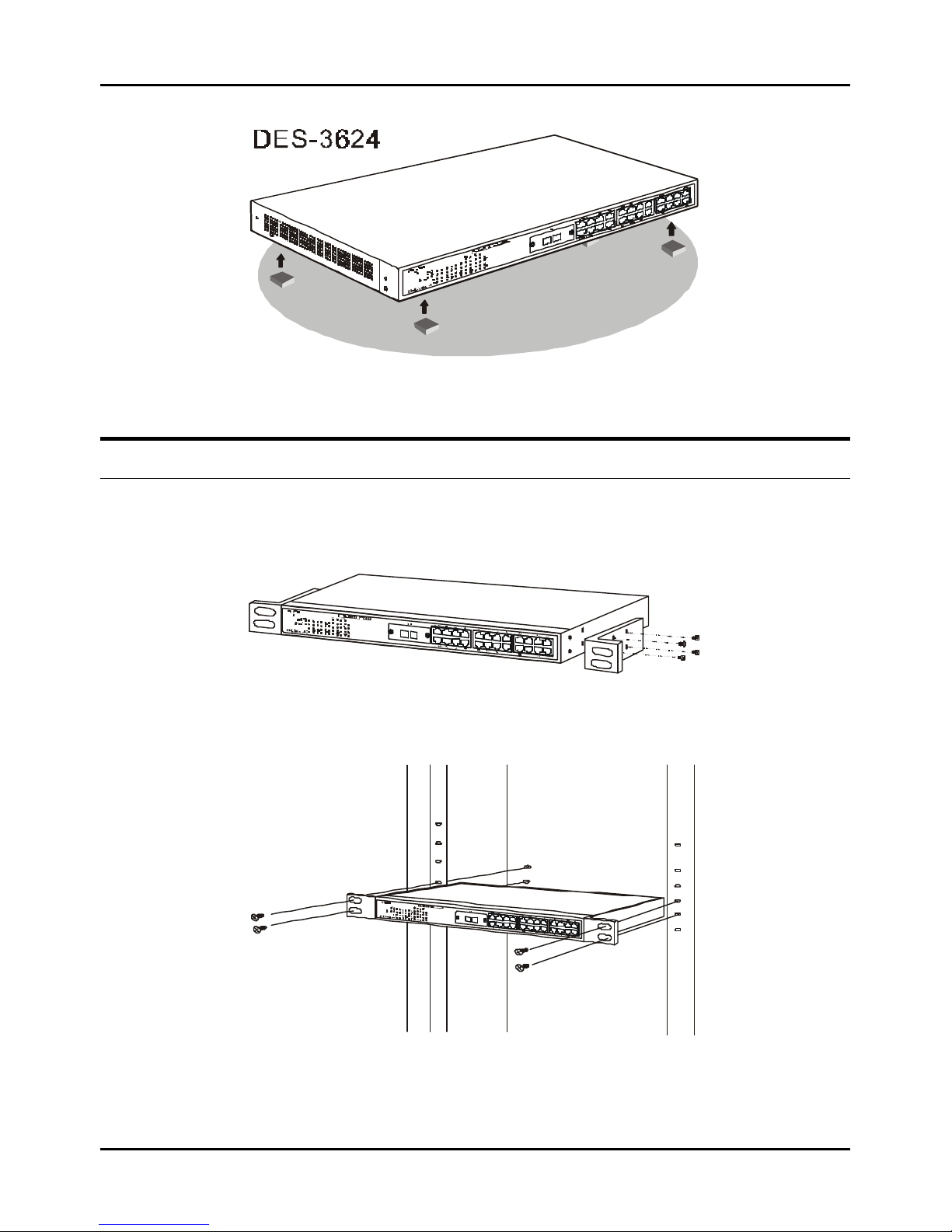
When installing the Switch on a desktop or shelf, the rubber feet included with the device must be first attached. Attach
these cushioning feet on the bottom at each corner of the device. Allow enough ventilation space between the device and the
objects around it.
Page 15
Stackable NWay Ethernet Switch User’s Guide
Unpacking and Setup 15
Figure 2-1. Switch installed on a Desktop or Shelf
Rack Installation
The Switch can be mounted in an EIA standard size, 19-inch rack, which can be placed in a wiring closet with other
equipment. To install, attach the mounting brackets on the Switch’s side panels (one on each side) and secure them with
the screws provided.
Figure 2-2A. Attaching the mounting brackets to the Switch
Then, use the screws provided with the equipment rack to mount the Switch in the rack.
Figure 2-2B. Installing the Switch in an equipment rack
Page 16

Stackable NWay Ethernet Switch User’s Guide
16 Unpacking and Setup
Power On
The Switch can be used with AC power sources 100 - 240 VAC, 50 - 60 Hz. The power switch is located at the rear of the
unit adjacent to the AC power connector and the system fan. The Switch’s power supply will adjust to the local power
source automatically and may be turned on without having any or all LAN segment cables connected.
After the power switch is turned on, the LED indicators should respond as follows:
♦ All LED indicators will momentarily blink. This blinking of the LED indicators represents a reset of the system.
♦ The power LED indicator will blink while the Switch loads onboard software and performs a self-test. After
approximately 40 seconds, the LED will light continuously to indicate the Switch is in a ready state.
♦ The console LED indicator will remain ON if there is a connection at the RS-232 port, otherwise this LED indicator
is OFF.
♦ The 100M LED indicator may remain ON or OFF depending on the transmission speed.
Power Failure
As a precaution, the Switch should be unplugged in case of power failure. When power is resumed, plug the Switch back in.
Page 17
Stackable NWay Ethernet Switch User’s Guide
Identifying External Components 17
33
3 IDENTIFYING E XTERNAL COMPONENTS
This chapter describes the front panel, rear panel, side panels, optional plug-in modules, and LED indicators of the Switch
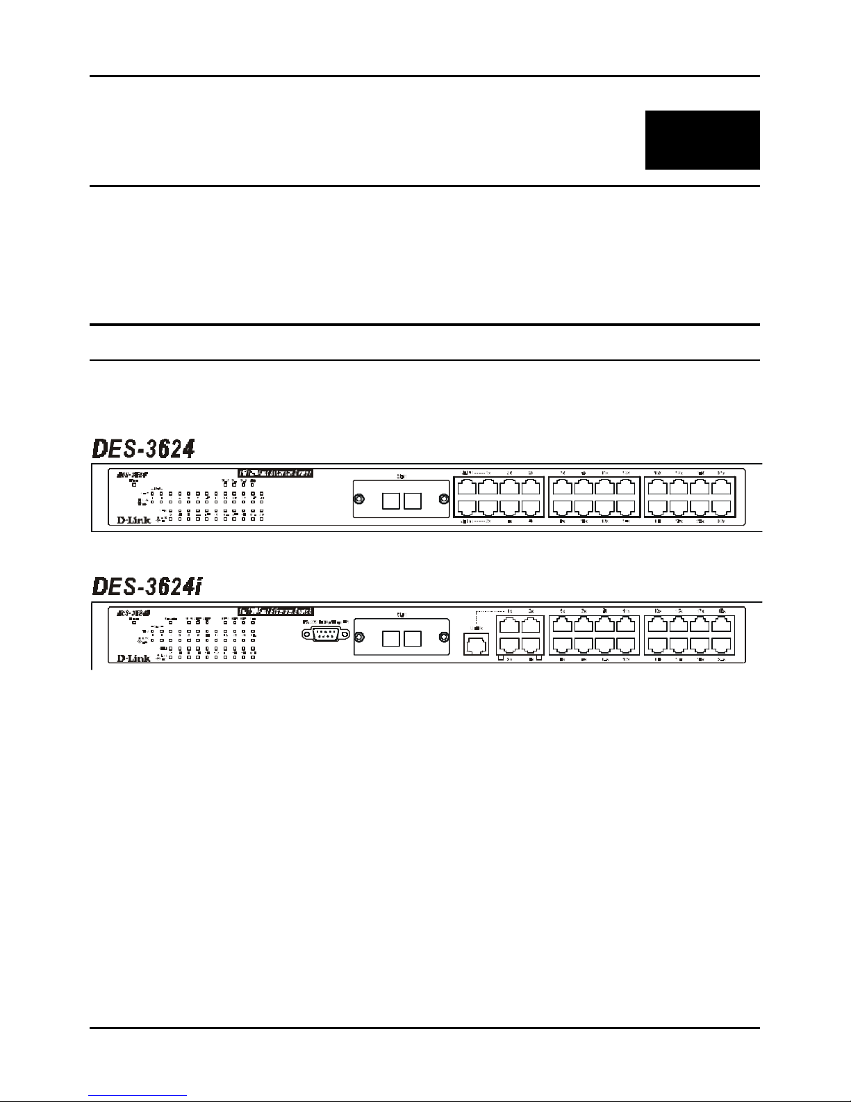
Front Panel
The front panel of the Switch consists of either 22 or 20 (10/100 Mbps) Ethernet/Fast Ethernet ports, two or one uplink
jacks, a slide-in module slot for 10/100 Mbps Ethernet ports, an RS-232 communication port (DES -3624i, DES-3624iF,
and DES-3624iFM only), and LED indicators.
Figure 3-1. Front panel view of the Switches
♦ Comprehensive LED indicators display the conditions of the Switch and status of the network. A description of
these LED indicators follows (see LED Indicators).
♦ An RS-232 DCE console port is used to diagnose the Switch via a connection to a PC and Local Console
Management (DES-3624i, DES-3624iF, and DES-3624iFM only).
♦ Twenty or twenty-two high performance NWay ports all operate at 10/100 Mbps for connection to servers and hubs.
All ports can be auto-negotiated between 10Mbps or 100Mbps.
♦ A slide-in module slot (labeled Slot1) for 10/100 Mbps Ethernet ports can accommodate the following modules: 2-
port TX, 2-port FX (MT-RJ), or 1-port FX (SC).
♦ One or two MDI-II uplink jacks are supported. Port numbers 1 and 2 on the DES -3624, DES -3624F, and DES-
3624FM are equipped with MDI-X jacks for normal end-node connections and MDI-II jacks for uplink connections.
Port number 1 on the DES-3624i, DES-3624iF, and DES-3624iFM are equipped with an MDI-X jack for normal end-
node connection and an MDI-II jack for uplink connection.
Page 18
Stackable NWay Ethernet Switch User’s Guide
18 Identifying External Components
Rear Panel
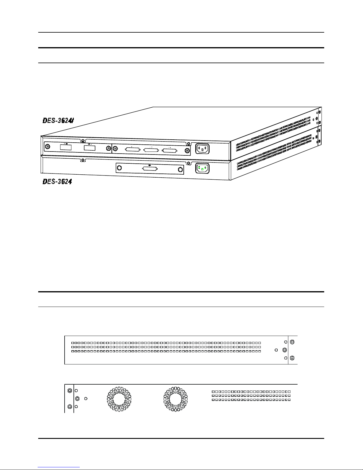
The rear panel of the DES-3624, DES-3624F, and DES-3624FM consist of a slot (labeled Slot2) for a Stacking input/output
port and an AC power connector. The rear panel of the DES -3624i, DES -3624iF, and DES-3624iFM consist of two slots
(labeled Slot2 and Slot3). Slot2 is for Stacking input/output ports Sio1, Sio2, and Sio3. Slot3 is for an optional Gigabit
Ethernet uplink (MDI-II) port. The following shows the rear panel of the Switches.
Figure 3-2. Rear panel view of the Switches
♦ The optional Gigabit Ethernet slide-in module is an uplink/MDI-II (media dependent interface) port for uplink to
another Switch (DES -3624i, DES-3624iF, and DES -3624iFM only). Two models are available, one-port and two port.
♦ The Stacking input/output port slide-in module in the rear panel is for stacking to another device to implement a
high-port count, manageable Switch. The three-port module is for a master device and a one-port module is for a
client device.
♦ The AC power connector is a three-pronged connector that supports the power cord. Plug in the female connector of
the provided power cord into this connector, and the male into a power outlet. Supported input voltages range from
100 ~ 240 VAC at 50 ~ 60 Hz.
Side Panels
The right side panel of the Switch contains two system fans (see the bottom part of the diagram below). The left side panel
contains heat vents.
Figure 3-3. Side panel views of the Switch
Page 19
Stackable NWay Ethernet Switch User’s Guide
Identifying External Components 19
♦ The system fans are used to dissipate heat. The sides of the system also provide heat vents to serve the same
purpose. Do not block these openings, and leave adequate space at the rear and sides of the Switch for proper
ventilation. Be reminded that without proper heat dissipation and air circulation, system components might
overheat, which could lead to system failure.
Stack Operation
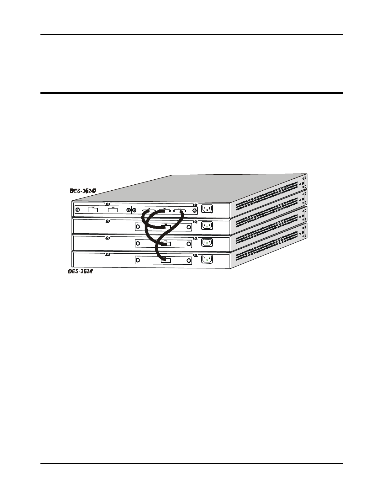
The DES -3624i, DES-3624iF, and DES -3624iFM are all intelligent Switches capable of acting as a master for up to
three slave Switches (DES -3624, DES-3624F, or DES-3624FM). Each port is referred to by unit ID and port number in
your DES-3624 Series stack.
To set up a stack, a one-port Stacking input/output module is needed for each client Switch and a three-port Stacking
input/output module is needed for the master Switch. Once the modules have been installed, use a cascade cable to
connect each client Switch to the master Switch.
Figure 3-4. Switch stack with one master and three slaves
Please note that two client switches can also be connected via the Stacking input/output ports.
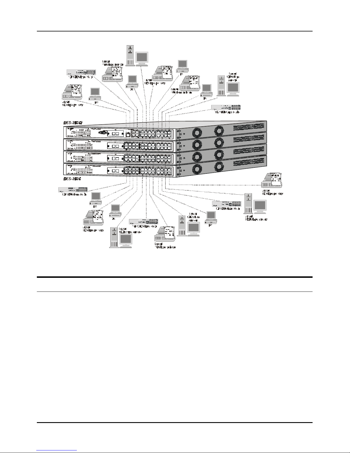
The following diagram displays some possible switch stack connections:
Page 20
Stackable NWay Ethernet Switch User’s Guide
20 Identi fying External Components
Figure 3-5. Switch stack with example of possible connections
Optional Plug-in Modules
The DES -3624i/DES-3624iF/DES-3624iFM Stackable NWay Ethernet Switch is able to accommodate a range of plug-in
modules in order to increase functionality and performance.
Page 21
Stackable NWay Ethernet Switch User’s Guide
Identifying External Components 21
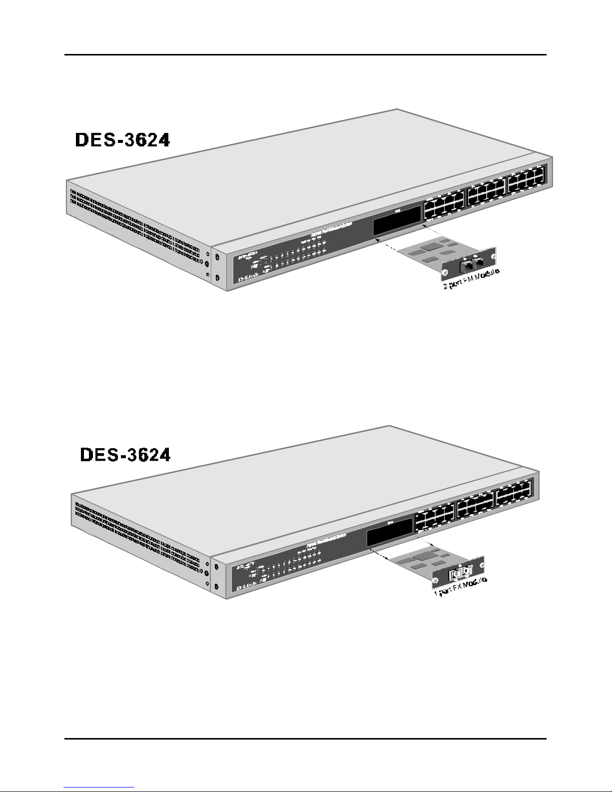
100BASE-FX (MT-RJ) Module
Figure 3-6. Two-port, 100BASE-FX (MT-RJ) module
♦ Two-port, front-panel module.
♦ Connects to 100BASE-FX devices at full- or half-duplex.
♦ Supports multi-mode fiber-optic cable connections of up to 412 meters in half-duplex or 2 km in full-duplex mode.
100BASE-FX (SC) Module
Figure 3-7. One -port, 100BASE-FX (SC) module
♦ One-port, front panel module.
♦ Connects to a 100BASE-FX device at full- or half-duplex.
♦ Supports multi-mode fiber-optic cable connections of up to 412 meters in half-duplex or 2 km in full-duplex mode.
Page 22
Stackable NWay Ethernet Switch User’s Guide
22 Identifying External Components
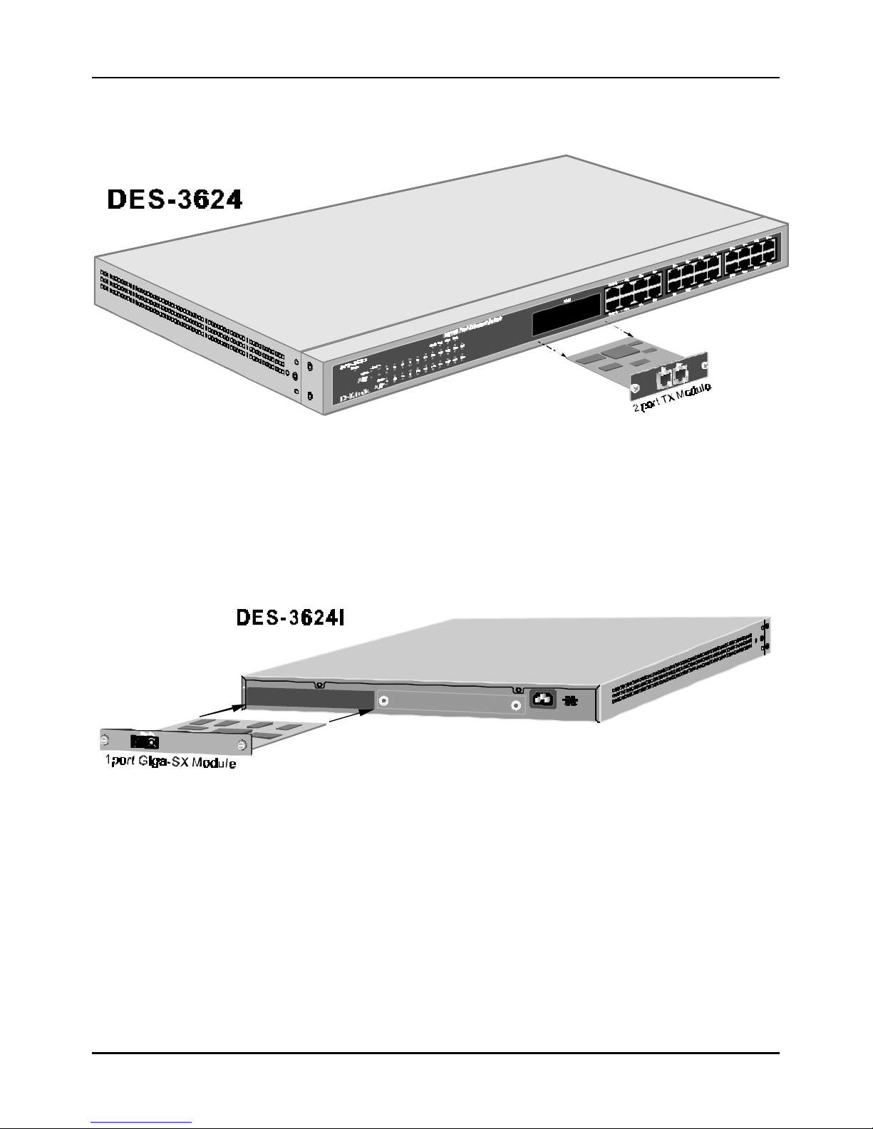
100BASE-TX Module
Figure 3-8. Two-port, 100BASE-TX module
♦ Two-port, front-panel module.
♦ Connects to 100BASE-TX devices at full- or half-duplex.
♦ Supports Category 5 UTP or STP cable connections of up to 100 meters.
1000BASE-SX Gigabit Module
Figure 3-9. One -port, 1000BASE-SX gigabit module
♦ One- or two-port, rear-panel module.
♦ Connects to 1000BASE-SX devices at full duplex.
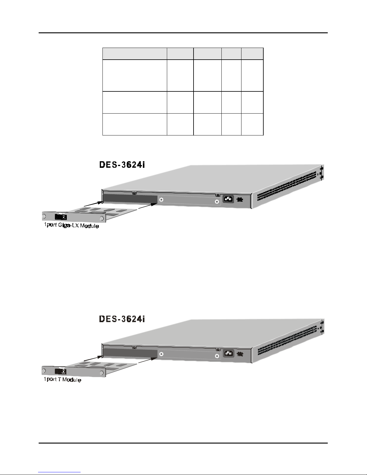
♦ Allows connections using multi-mode fiber optic cable in the following configurations:
Page 23
Stackable NWay Ethernet Switch User’s Guide
Identifying External Components 23
62.5µµm 62.5µµm 50µµm 50µµ m
Modal bandwidth
(min. overfilled launch)
Unit: MHz*km
160 200 400 500
Operating distance
Unit: meters
220 275 500 550
Channel insertion loss
Unit: dB
2.33 2.53 3.25 3.43
1000BASE-LX Gigabit Module
Figure 3-10. One -port, 1000BASE-LX gigabit module
♦ One- or two-port, rear-panel module.
♦ Connects to a 1000BASE-LX device at full duplex.
♦ Allows connections up to 5 km in length using single-mode fiber optic cable.
1000BASE-T Copper Gigabit Module
Figure 3-11. One -port, 1000BASE-T gigabit module
♦ One- or two-port, rear-panel module.
♦ Connects to 1000BASE-T devices at 1000M/full duplex, 100M/full duplex, 100M/half duplex, and Auto.
Page 24

Stackable NWay Ethernet Switch User’s Guide
24 Identifying External Components
♦ Supports Category 5+ or higher cable connections of up to 100 meters.
LED Indicators
The LED indicators of the Switch include Power, Console, Slot, Giga, Speed, and Link/Act. The following shows the LED
indicators for the Switch along with an explanation of each indicator.
Figure 3-12. The Switch LED indicators
♦ Power This indicator on the front panel should light green after approximately 2 seconds to indicate the ready
state of the Switch when the device is powered on. The LED will blink when the Power-On Self-Test (POST) is
running or if the system’s configuration has changed. This LED will light orange when an error occurs.
♦ Console This indicator is lit green when the switch is being managed via out-of-band/local console management
through the RS-232 console port using a straight -through serial cable. When a secured connection is established,
this LED is lit. The indicator blinks when the console RS-232 is accessed.
♦ Slot2 This indicator is lit green when a slide-in module is present in the rear panel of the Switch.
♦ Slot3 This indicator is lit green when a slide-in module is present in the rear panel of the Switch.
♦ Giga1 This indicator is lit green when a link is established. It blinks green when the Gigabit port is active.
♦ Giga2 This indicator is lit green when a link is established. It blinks green when the Gigabit port is active.
♦ Sio1 This indicator is lit green when a Stacking IO port is present in the rear panel of the Switch.
♦ Sio2 This indicator is lit green when a Stacking IO port is present in the rear panel of the Switch.
♦ Sio3 This indicator is lit green when a Stacking IO port is present in the rear panel of the Switch.
Page 25

Stackable NWay Ethernet Switch User’s Guide
Identifying External Components 25
♦ 100M These indicators are illuminated green when a 100 Mbps device is connected to any of the 22+2 or 20+2 ports
or uplink port. If a 10 Mbps device is connected to any of the 24 ports or uplink port, these LEDs remain dark. When
a port is active, these indicators will blink green.
♦ Link/Act These indicators are lit when there is a secure connection (or link) to a device at any of the ports. The
LEDs blink whenever there is reception or transmission (i.e. Activity --Act) of data occurring at a port.
Page 26
Stackable NWay Ethernet Switch User’s Guide
26 Connecting The Switch
44
4 C ONNECTING THE SWITCH
This chapter describes how to connect the Switch to your Ethernet network.
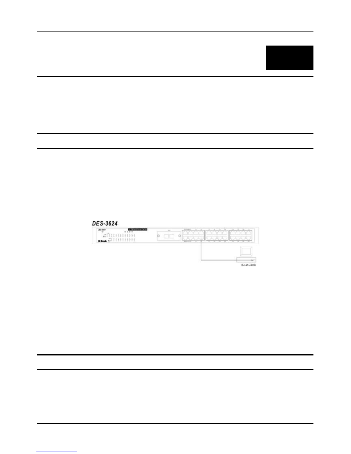
Switch to End Node
End nodes include PCs outfitted with a 10, 100 or 10/100 Mbps RJ-45 Ethernet/Fast Ethernet Network Interface Card
(NIC) and most routers. The RJ-45 UTP ports on NICs and most routers are MDI-II. When using a normal straight-through
cable, an MDI-II port must connect to an MDI-X port.
An end node can be connected to the Switch via a two-pair Category 3, 4, 5 UTP/STP straight cable (be sure to use Category
5 UTP or STP cabling for 100 Mbps Fast Ethernet connections). The end node should be connected to any of the twenty -two
ports (1x - 22x) of the Switch or to either of the two 100BASE-TX ports on the front-panel module that came preinstalled
on the Switch. An end node should not be connected to an Uplink port (unless using a crossover cable), and if the top Uplink
port is in use, Port 1x must remain vacant; if the bottom Uplink port is in use, Port 2x cannot be used.
Figure 4-1. Switch connected to an End Node
The LED indicators for the port the end node is connected to are lit according to the capabilities of the NIC. If LED
indicators are not illuminated after making a proper connection, check the PC’s LAN car d, the cable, switch conditions, and
connections.
The following LED indicator states are possible for an end node to switch connection:
1. The 100M LED indicator comes ON for a 100 Mbps and stays OFF for 10 Mbps.
2. The Link/Act LED indicator lights up upon hooking up a PC that is powered on.
Switch to Hub or Switch
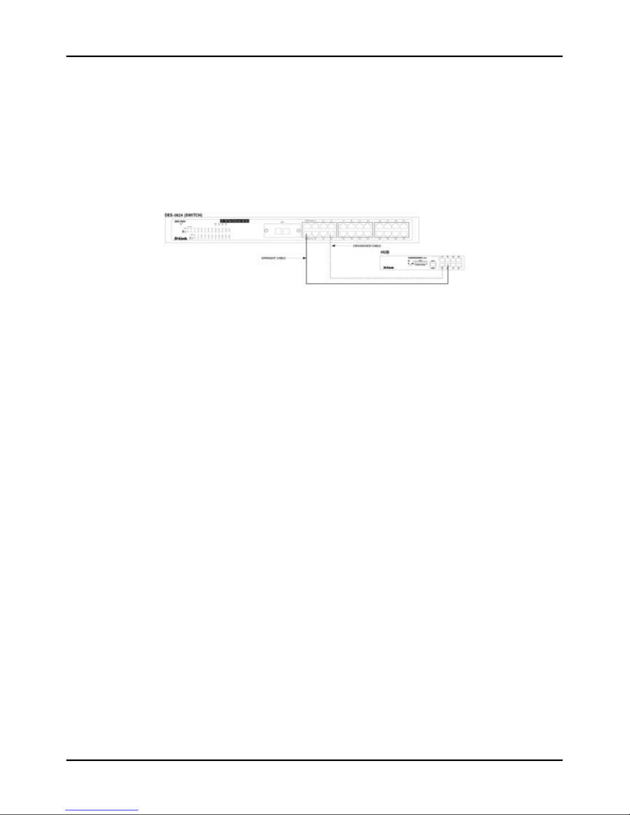
These connections can be accomplished in a number of ways. The most important consideration is that when using a
normal, straight -through cable, the connection should be made between a normal crossed port (Port 1x, 2x, etc.) and an
Uplink (MDI-II) port. If you are using a crossover cable, the connection must be made from Uplink to Uplink, or from a
crossed port to another crossed port.
Page 27
Stackable NWay Ethernet Switch User’s Guide
Connecting The Switch 27
♦ A 10BASE-T hub or switch can be connected to the Switch via a two-pair Category 3, 4 or 5 UTP/STP straight cable.
♦ A 100BASE-TX hub or switch can be connected to the Switch via a four-pair Category 5 UTP/STP straight cable.
If the other switch or hub contains an unused Uplink port, we suggest connecting the other device’s Uplink (MDI-II) port to
any of the switch’s (MDI-X) ports (1x - 22x, or one of the 100BASE -TX module ports) using a normal straight-through cable,
as shown below.
If the other device does not have an unused Uplink port, make the connection with a normal straight-through cable from
one of the Uplink ports on the switch to any normal crossed port on the hub. Alternatively, if you have a crossover cable you
can save the Uplink ports for other connections and make this one from a crossed port to another crossed port.
Figure 4-2. Switch connected to a normal (non-Uplink) port on a hub or switch using a straight or crossover
cable
10BASE-T Device
For a 10BASE -T device, the Switch’s LED indicators should display the following:
♦ 100M LED speed indicator is OFF.
♦ Link/Act indicator is ON.
100BASE-TX Device
For a 100BASE -TX device, the Switch’s LED indicators should display the following:
♦ 100M LED speed indicator is ON.
♦ Link/Act is ON.
Page 28

Stackable NWay Ethernet Switch User’s Guide
28 Switch Management Concepts
55
5 S WITCH MANAGEMENT CONCEPTS
This chapter discusses many of the features used to manage the switch, and explains many concepts and important points
regarding these features. Configuring the Switch to implement these concepts is discussed in detail in the next chapters.
Local Console Management
Local console management involves the administration of the Switch via a direct connection to the RS-232 DCE console
port. This is an Out -Of-Band connection, meaning that it is on a different circuit than normal network communications,
and thus works even when the network is down.
The local console mana gement connection involves a terminal or PC running terminal emulation software to operate the
Switch’s built-in console program (see Chapter 6, “Using the Console Interface”). Using the console program, a network
administrator can manage, control and monitor the many functions of the Switch.
Hardware components in the Switch allow it to be an active part of a manageable network. These components include a
CPU, memory for data storage, other related hardware, and SNMP agent firmware. Activities on the Switch can be
monitored with these components, while the Switch can be manipulated to carry out specific tasks.
Diagnostic (Console) Port (RS-232 DCE)
Out-of-band management requires connecting a terminal, such as a VT-100 or a PC running terminal emulation program
(such as HyperTerminal, which is automatically installed with Microsoft Windows) a to the RS-232 DCE console port of
the Switch. Switch management using the RS-232 DCE console port is called Local Console Management to differentiate
it from management done via management platforms, such as D -View, HP OpenView, etc.
The console port is set for the following configuration:
◊ Baud rate: 9,600
◊ Data width: 8 bits
◊ Parity: none
◊ Stop bits: 1
◊ Flow Control none
Make sure the terminal or PC you are using to make this connection is configured to match these settings.
If you are having problems making this connection on a PC, make sure the emulation is set to VT-100 or ANSI. If you
still don’t see anything, try hitting <Ctrl> + r to refresh the screen.
Page 29

Stackable NWay Ethernet Switch User’s Guide
Switch Management Concepts 29
IP Addresses and SNMP Community Names
Each Switch has its own IP Address, which is used for communication with an SNMP network manager or other TCP/IP
application (for example BOOTP, TFTP). You can change the default Switch IP Address to meet the specification of your
networking address scheme.
In addition, you can also set an IP Address for a gateway router. This becomes necessary when the network management
station is located on a different IP network as the Switch, making it necessary for management packets to go through a
router to reach the network manager, and vice-versa.
For security, you can set in the Switch a list of IP Addresses of the network managers that you allow to manage the Switch.
You can also change the default Community Name in the Switch and set access rights of these Community Names.
Traps
Traps are messages that alert you of events that occur on the Switch. The events can be as serious as a reboot (someone
accidentally turned OFF the Switch), or less serious like a port status change. The Switch generates traps and sends them
to the network manager (trap managers). The following lists the types of events that can take place on the Switch.
◊ System resets
◊ Errors
◊ Status changes
◊ Topology changes
◊ Operation
You can also specify which network managers may receive traps from the Switch by setting a list of IP Addresses of the
authorized network managers.
Trap managers are special users of the network who are given certain rights and access in overseeing the maintenance of
the network. Trap managers will receive traps sent from the Switch; they must immediately take certain actions to avoid
future failure or breakdown of the network.
The following are trap types a trap manager will receive:
♦ Cold Start This trap signifies that the Switch has been powered up and initialized such that software settings
are reconfigured and hardwar e systems are rebooted. A cold start is different from a factory reset.
♦ Warm Start This trap signifies that the Switch has been rebooted, however the Power-On Self-Test (POST) is
skipped.
♦ Authentication Failure This trap signifies that someone has tried to logon to the switch using an invalid
SNMP community name. The switch automatically stores the source IP address of the unauthorized user.
♦ New Root This trap indicates that the Switch has become the new root of the Spanning Tree, the trap is sent by a
bridge soon after its election as the new root. This implies that upon expiration of the Topology Change Timer the
new root trap is sent out immediately after the Switch’s selection as a new root.
♦ Topology Change A Topology Change trap is sent by the Switch when any of its configured ports transitions
from the Learning state to the Forwarding state, or from the Forwarding state to the Blocking state. The trap is not
sent if a new root trap is sent for the same transition.
Page 30

Stackable NWay Ethernet Switch User’s Guide
30 Switch Management Concepts
♦ Link Change Event This trap is sent whenever the link of a port changes from link up to link down or from link
down to link up.
♦ Port Partition This trap is sent whenever a port is partitioned as a result of more than sixty-one collisions on
the port (i.e., it is automatically partitioned). The number of collisions that triggers this trap is the same at either
10Mbps or 100Mbps.
♦ Broadcast Storm This trap is sent whenever the port reaches the broadcast storm rising or falling threshold.
MIBs
Management information and counters are stored in the Switch in the Management Information Base (MIB). The Switch
uses the standard MIB -II Management Information Base module. Consequently, values for MIB objects can be retrieved
from any SNMP-based network manager software. In addition to the standard MIB -II, the Switch also supports its own
proprietary enterprise MIB as an extended Management Information Base. These MIBs may also be retrieved by
specifying the MIB’s Object-Identity (OID) at the network manager. MIB values can be either read-only or read-write.
Read-only MIBs variables can be either constants that are programmed into the Switch, or variables that change while the
Switch is in operation. Examples of read-only constants are the number of ports and types of ports. Examples of read-only
variables are the statistics counters such as the number of errors that have occurred, or how many kilobytes of data have
been received and forwarded through a port.
Read-write MIBs are variables usually related to user-customized configurations. Examples of these are the Switch’s IP
Address, Spanning Tree Algorithm parameters, and port status.
If you use a third-party vendors’ SNMP software to manage the Switch, a diskette listing the Switch’s propriety enterprise
MIBs can be obtained by request. If your software provides functions to browse or modify MIBs, you can also get the MIB
values and change them (if the MIBs’ attributes permit the write operation). This process however can be quite involved,
since you must know the MIB OIDs and retrieve them one by one.
Packet Forwarding
The Switch learns the network configuration and uses this information to forward packets. This reduces the traffic
congestion on the network, because packets, instead of being transmitted to all segments, are transmitted to the
destination only. Example: if Port 1 receives a packet destined for a station on Port 2, the Switch transmits that packet
through Port 2 only, and transmits nothing through the other ports.
Aging Time
The Aging Time is a parameter that affects the auto-learn process of the Switch in terms of the network configuration.
Dynamic Entries, which make up the auto-learned-node address, are aged out of the address table according to the Aging
Time that you set.
The Aging Time can be from 10 seconds to 9999 seconds. A very long Aging Time can result with the out-of-date Dynamic
Entries that may cause incorrect packet filtering/forwarding decisions.
On the other hand, if the Aging Time is too short, many entries may be aged out soon, resulting in a high percentage of
received packets whose source addresses cannot be found in the address table, in which case the Switch will broadcast the
packet to all ports, negating many of the benefits of having a switch.
Page 31

Stackable NWay Ethernet Switch User’s Guide
Switch Management Concepts 31
Filtering Database
A switch uses a filtering database to segment the network and control communications between segments. It also
filters packets off the network for intrusion control (MAC Address filtering).
For port filtering, each port on the switch is a unique collision domain and the switch filters (discards) packets whose
destination lies on the same port as where it originated. This keeps local packets from disrupting communications on
other parts of the network.
For intrusion control, whenever a switch encounters a packet originating from or destined to a MAC address defined by
the user, the switch will discard the packet.
Filtering includes:
1. Dynamic filtering Automatic learning and aging of MAC addresses and their location on the network. Filtering
occurs to keep local traffic confined to its segment.
2. MAC address filtering The manual entry of specific MAC addresses to be filtered from the network.
3. Filtering done by the Spanning Tree Protocol Can filter packets based on topology, making sure that
signal loops don’t occur.
4. Filtering done for VLAN integrity. Packets from a member of a VLAN (VLAN 2, for example) destined for a
device on another VLAN (VLAN 3) will be filtered.
Spanning Tree Algorithm
The Spanning Tree Algorithm (STA) in the Switch allows you to create alternative paths (with multiple switches or other
types of bridges) in your network. These backup paths are idle until the Switch determines that a problem has developed
in the primary paths. When a primary path is lost, the switch providing the alternative path will automatically go into
service with no operator intervention. This automatic network reconfiguration provides maximum uptime to network users.
The concept of the Spanning Tree Algorithm is a complicated and complex subject and must be fully researched and
understood. Please read the following before making any changes.
♦ Network loop detection and prevention With STA, there will be only one path between any two LANs. If
there is more than one path, forwarded packets will loop indefinitely. STA detects any looped path and selects the
path with the lowest path cost as the active path, while blocking the other path and using it as the backup path.
♦ Automatic topology re-configuration When the path for which there is a backup path fails, the backup
path will be automatically activated, and STA will automatically re-configure the network topology.
STA Operation Levels
STA operates on two levels: the bridge level and the port level. On the bridge level, STA calculates the Bridge Identifier for
each Switch, then sets the Root Bridge and the Designated Bridges. On the port level, STA sets the Root Port and
Designated Ports. Details are as follows:
On the Bridge Level
♦ Root Bridge The switch with the lowest Bridge Identifier is the Root Bridge. Naturally, you will want the Root
Bridge to be the best switch among the switches in the loop to ensure the highest network performance and
reliability.
Page 32

Stackable NWay Ethernet Switch User’s Guide
32 Switch Management Concepts
♦ Bridge Identifier This is the combination of the Bridge Priority (a parameter that you can set) and the MAC
address of the switch. Example: 4 00 80 C8 00 01 00, where 4 is the Bridge Priority. A lower Bridge Identifier
results in a higher priority for the switch, and thus increases it probably of being selected as the Root Bridge.
♦ Designated Bridge From each LAN segment, the attached Bridge that has the lowest Root Path Cost to the
Root Bridge is the Designated Bridge. It forwards data packets for that LAN segment. In cases where all Switches
have the same Root Path Cost, the switch with the lowest Bridge Identifier becomes the Designated Bridge.
♦ Root Path Cost The Root Path Cost of a switch is the sum of the Path Cost of the Root Port and the Root Path
Costs of all the switches that the packet goes through. The Root Path Cost of the Root Bridge is zero.
♦ Bridge Priority This is a parameter that users can set. The smaller the number you set, the higher the Bridge
Priority is. The higher the Bridge Priority, the better the chance the Switch will be selected as the Root Bridge.
On the Port Level
♦ Root Port Each switch has a Root Port. This is the port that has the lowest Path Cost to the Root Bridge. In case
there are several such ports, then the one with the lowest Port Identifier is the Root Port.
♦ Designated Port This is the port on each Designated Bridge that is attached to the LAN segment for which the
switch is the Designated Bridge.
♦ Port Priority The smaller this number, the higher the Port Priority is. With higher Port Priority, the higher the
probability that the port will be selected as the Root Port.
♦ Path Cost This is a changeable parameter and may be modified according to STA specifications. The 1000Mbps
segment has an assigned Path Cost of 4, the 100Mbps segment has an assigned Path Cost of 19, and each 10Mbps
segment has an assigned cost of 100. These values will change dynamically when port trunking is enabled.
User-Changeable STA Parameters
The factory default setting should cover the majority of installations. However, it is advisable to keep the default settings
as set at the factory, unless it is absolutely necessary. The user changeable parameters in the Switch are as follows:
♦ Bridge Priority A Bridge Priority can be from 0 to 65535. 0 is equal to the highest Bridge Priority.
♦ Bridge Hello Time The Hello Time can be from 1 to 10 seconds. This is the interval between two transmissions
of BPDU packets sent by the Root Bridge to tell all other Switches that it is indeed the Root Bridge. If you set a
Hello Time for your Switch, and it is not the Root Bridge, the set Hello Time will be used if and when your Switch
becomes the Root Bridge.
Note: The Hello Time cannot be longer than the Max. Age. Otherwise, a configuration error will occur.
♦ Bridge Max. Age The Max. Age can be from 6 to 40 seconds. At the end of the Max. Age, if a BPDU has still not
been received from the Root Bridge, your Switch will start sending its own BPDU to all other Switches for
permission to become the Root Bridge. If it turns out that your Switch has the lowest Bridge Identifier, it will
become the Root Bridge.
♦ Bridge Forward Delay The Forward Delay can be from 4 to 30 seconds. This is the time any port on the Switch
spends in the listening state while moving from the blocking state to the forwarding state.
Observe the following formulas when you set the above parameters:
1. Max. Age 2 x (Forward Delay - 1 second)
2. Max. Age 2 x (Hello Time + 1 second)
Page 33
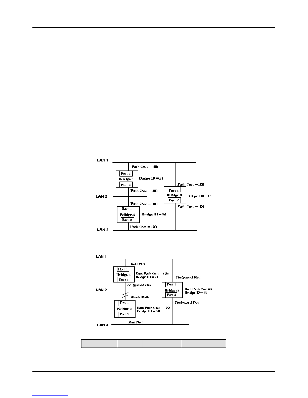
Stackable NWay Ethernet Switch User’s Guide
Switch Management Concepts 33
♦ Port Priority A Port Priority can be from 0 to 255. The lower the number, the greater the probability the port
will be chosen as the Root Port.
Illustration of STA
A simple illustration of th ree Bridges (or the Switch) connected in a loop is depicted in Figure 5-1. In this example, you can
anticipate some major network problems if the STA assistance is not applied. For instance, if Bridge 1 broadcasts a
packet to Bridge 2, Bridge 2 will broadcast it to Bridge 3, and Bridge 3 will broadcast it to Bridge 1 and so on. The
broadcast packet will be passed indefinitely in a loop, causing a serious network failure.
To alleviate network loop problems , STA can be applied as shown in Figure 5-2. In this example, STA breaks the loop by
blocking the connection between Bridge 1 and 2. The decision to block a particular connection is based on the STA
calculation of the most current Bridge and Port settings. Now, if Bridge 1 broadcasts a packet to Bridge 3, then Bridge 3
will broadcast it to Bridge 2 and the broadcast will end there.
STA setup can be somewhat complex. Therefore, you are advised to keep the default factory settings and STA will
automatically assign root bridges/ports and block loop connections. However, if you need to customize the STA parameters,
refer to Table 5-1.
Figure 5-1. Before Applying the STA Rules
Figure 5-2. After Applying the STA Rules
STA parameters Settings Effects Comment
Page 34

Stackable NWay Ethernet Switch User’s Guide
34 Switch Management Concepts
Bridge Priority lower the #,
higher the
priority
Increases chance
of becoming the
Root Bridge
Avoid, if the switch
is used in workgroup
level of a large
network
Hello Time 1 - 10 sec. No effect, if not
Root Bridge
Never set greater
than Max. Age Time
Max. Age Time 6 - 40 sec. Compete for Root
Bridge, if BPDU
is not received
Avoid low number
for unnecessary reset
of Root Bridge
Forward Delay 4 - 30 sec. High # delays the
change in state
Max. Age ≤ 2 x
(Forward Delay - 1)
Max. Age ≥ 2 x
(Hello Time + 1)
Port Level STA parameters
Enable / Disable Enable /
Disable
Enable or disable
this LAN segment
Disable a port for
security or problem
isolation
Port Priority
lower the #,
higher the
priority
Increases chance
of become Root
Port
Table 5-1. User-selective STA parameters
Port Trunking
Port trunking is used to combine a number of ports together to make a single high-bandwidth data pipeline. The
participating parts are called members of a trunk group, with one port designated as the anchor of the group. Since all
members of the trunk group must be configured to operate in the same manner, all settings changes made to the anchor
port are applied to all members of the trunk group. Thus, when configuring the ports in a trunk group, you only need to
configure the anchor port.
The Switch supports 3 trunk groups, which may include from 2 to 8 switch ports each, except for the third trunk group
which consists of the 2 ports of the Slot 1, 100BASE-TX or 100BASE-FX front -panel module. The anchor port for the first
group is preset as port 5, the anchor port for the second group is port 13 and the anchor port for the third group is the first
port (1x) on the 2-port module.
Page 35
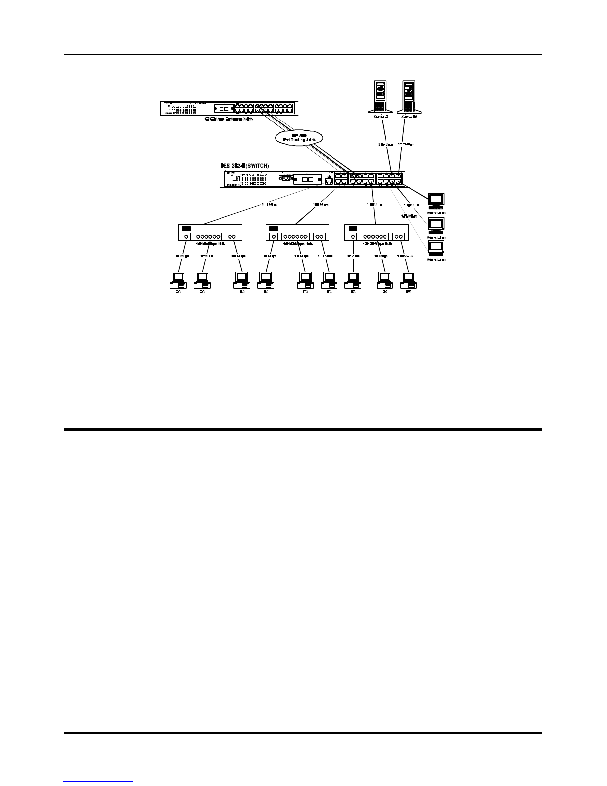
Stackable NWay Ethernet Switch User’s Guide
Switch Management Concepts 35
Figure 5-3. Port trunking example
The switch treats all ports in a trunk group as a single port. As such, trunk ports will not be blocked by Spanning Tree
(unless a redundant link with higher STP priority is present).
Data transmitted to a specific host (destination address) will always be transmitted over the same port in a trunk group.
This allows packets in a data stream to arrive in the same order they were sent. A trunk connection can be made with any
other switch that maintains host-to-host data streams over a single trunk port. A trunk connection cannot be made with
switches that perform load-balancing on a per-packet basis.
VLANs & MAC-Based Broadcast Domains
VLANs are a collection of users or switch ports grouped together in a secure, autonomous broadcast and multicast domain.
The main purpose of setting up VLANs or a broadcast domain on a network is to limit the range and effects of broadcast
packets.
Two types of VLANs are implemented on the Switch: 802.1Q VLANs and port -based VLANs. MAC-based broadcast
domains are a third option. Only one type of VLAN or broadcast domain can be active on the Switch at any given time,
however. Thus, you will need to choose the type of VLAN or broadcast domain you wish to setup on your network and
configure the Switch accordingly. 802.1Q VLANs support IEEE 802.1Q tagging, which enables them to span the entire
network (assuming all switches on the network are IEEE 802.1Q-compliant). In contrast, MAC-based broadcast domains
are limited to the Switch and devices directly connected to them.
All VLANs allow a network to be segmented in order to reduce the size of broadcast domains. All broadcast, multicast,
and unknown packets entering the Switch on a particular VLAN will only be forwarded to the stations or ports (802.1Q
and port -based) that are members of that VLAN. 802.1Q and port-based VLANs also limit unicast packets to members of
the VLAN, thus providing a degree of security to your network.
Another benefit of 802.1Q and port -based VLANs is that you can change the network topology without physically moving
stations or changing cable connections. Stations can be ‘moved’ to another VLAN and thus communicate with its members
and share its resources, simply by changing the port VLAN settings from one VLAN (the sales VLAN, for example) to
another VLAN (the marketing VLAN). This allows VLANs to accommodate network moves, changes and additions with
the utmost flexibility. MAC-based broadcast domains, on the other hand, allow a station to be physically moved yet still
belong to the same broadcast domain without having to change and configuration settings.
Page 36

Stackable NWay Ethernet Switch User’s Guide
36 Switch Management Concepts
The untagging feature of IEEE 802.1Q VLANs allows VLANs to work with legacy switches that don’t recognize VLAN
tags in packet headers. The tagging feature allows VLANs to span multiple 802.1Q-compliant switches through a single
physical connection and allows Spanning Tree to be enabled on all ports and work normally (BPDU packets are not
tagged).
MAC-Based Broadcast Domains
The Switch supports up to 12 MAC-based broadcast domains, which are by their nature, limited to the Switch itself and
the devices connected directly to it.
Since MAC addresses are hard-wired into a station’s network interface card (NIC), MAC-based broadcast domains enable
network managers to move a station to a different physical location on the network and have that station automatically
retain its broadcast domain membership. This provides the network with a high degree of flexibility since even notebook
PC’s can plug into any available port on a network and communicate with the same people and use the same resources
that have been allocated to the broadcast domain in which it is a member.
Since MAC-based broadcast domains do not restrict the transmission of known unicast frames to other broadcast
domains, they can only be used to define limited broadcast domains. As such, they are best implemented on networks
where stations are frequently moving, for example where people using notebook PCs are constantly plugging into different
parts of the network.
Setting up MAC-based broadcast domains is a relatively straightforward process. Simply create the broadcast domain by
assigning it a name (description) and add MAC addresses for the stations that will be members.
IEEE 802.1Q VLANs
The Switch supports up to 2000 802.1Q VLANs. 802.1Q VLANs limit traffic that flows into and out of switch ports. Thus,
all devices connected to a port are members of the VLAN(s) the port belongs to, whether there is a single computer directly
connected to a switch, or an entire department.
On 802.1Q VLANs, NICs do not need to be able to identify 802.1Q tags in packet headers. NICs send and receive normal
Ethernet packets. If the packet’s destination lies on the same segment, communications take place using normal Ethernet
protocols. Even though this is always the case, when the destination for a packet lies on another Switch port, VLAN
considerations come into play to decide if the packet gets dropped by the Switch or delivered.
There are two key components to understanding 802.1Q VLANs: Port VLAN ID numbers (PVIDs) and VLAN ID numbers
(VIDs). Both variables are assigned to a switch port, but there are important differences between them. A user can only
assign one PVID to each switch port. The PVID defines which VLAN a packet belongs to when packets need to be
forwarded to another switch port or somewhere else on the network. On the other hand, a user can define a port as a
member of multiple VLANs (VIDs), allowing the segment connected to it to receive packets from many VLANs on the
network. These two variables control a port’s ability to transmit and receive VLAN traffic, and the difference between
them provides network segmentation, while still allowing resources to be shared across more than one VLAN.
802.1Q VLAN Segmentation
The following example is helpful in explaining how 802.1Q VLAN segmentation works. Take a packet that is transmitted
by a machine on Port 1 that is a member of VLAN 2 and has the Port VLAN ID number 2 (PVID=2). If the destination lies
on another port (found through a normal forwarding table lookup), the Switch then looks to see if the other port (Port 10) is
a member of VLAN 2 (and can therefore receive VLAN 2 packets). If port 10 is not a member of VLAN 2, then the packet
will be dropped by the Switch and will not reach its destination. If Port 10 is a member of VLAN 2, the packet will go
through. This selective forwarding feature based on VLAN criteria is how VLANs segment networks. The key point being
that Port 1 will only transmit on VLAN 2, because it’s Port VLAN ID number is 2 (PVID=2).
Page 37
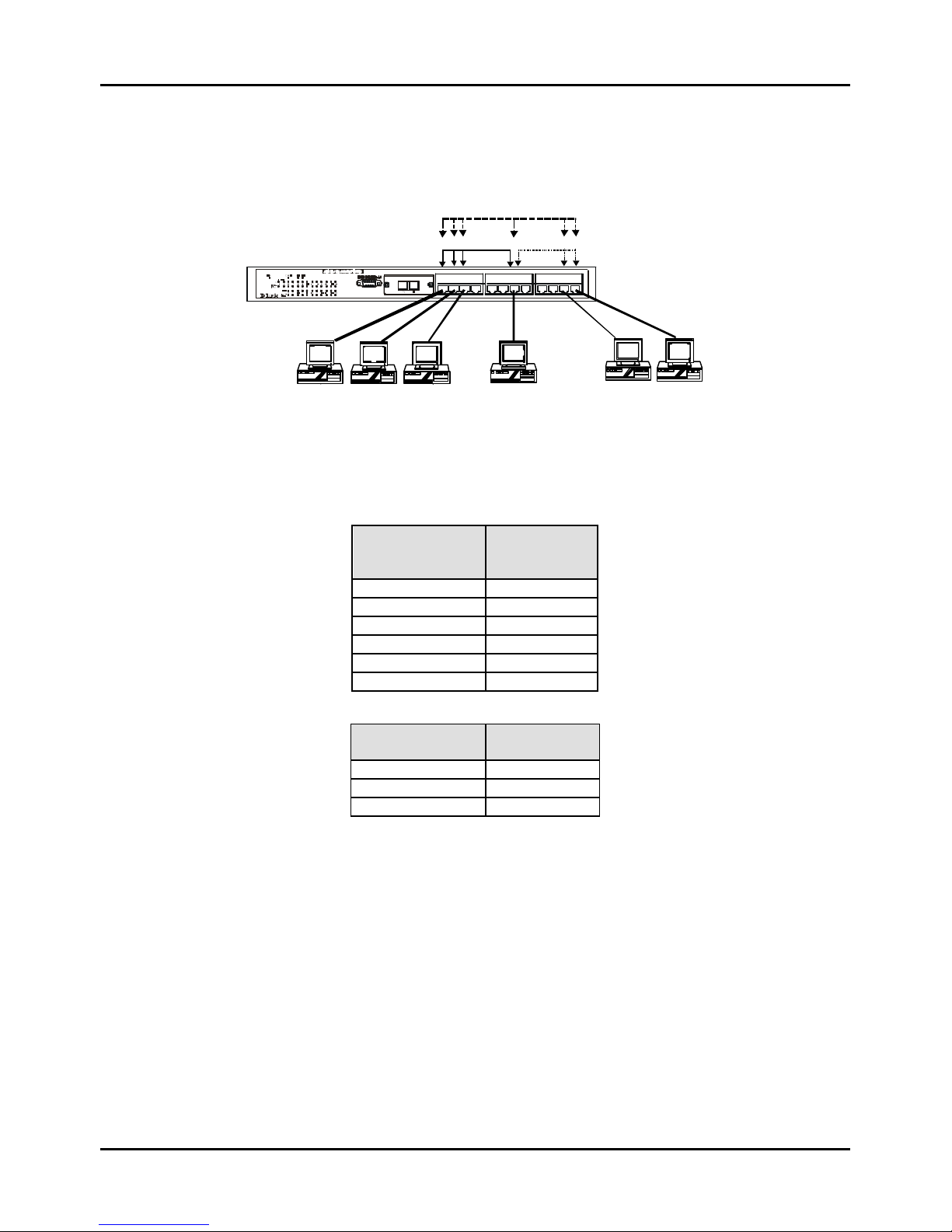
Stackable NWay Ethernet Switch User’s Guide
Switch Management Concepts 37
Sharing Resources Across 802.1Q VLANs
Network resources such as printers and servers however, can be shared across 802.1Q VLANs. This is achieved by setting
up overlapping VLANs as shown in the diagram below.
VLAN 1
Por t
VIDs = 1
VLAN 2
Por t
VID s = 2
Po rt
PV ID = 3
VLAN3
1 2 3 4 5 6 7 8 9 1 0 11 1 2
Graphics
Workstations
Workstations
Network
Serve
r
Figure 5-4. Example of typical VLAN configuration
In the above example, there are three different 802.1Q VLANs and each port can transmit packets on one of them
according to their Port VLAN ID (PVID). However, a port can receive packets on all VLANs (VID) that it belongs to. The
assignments are as follows:
PVID
(Port VLAN
ID)
Ports
1 Port 1
1 Port 2
1 Port 3
2 Port 11
2 Port 12
3 Port 7
VID
(VLAN ID)
Member
Ports
1 1,2,3,7
2 7,11,12
3 1,2,3,7,11,12
Table 5-2. VLAN assignments for Figure 5-4
The server attached to Port 7 is shared by VLAN 1 and VLAN 2 because Port 7 is a member of both VLANs (it is listed as
a member of VID 1 and 2). Since it can receive packets from both VLANs, all ports can successfully send packets to it to be
printed. Ports 1, 2 and 3 send these packets on VLAN 1 (their PVID=1), and Ports 11 and 12 send these packets on VLAN
2 (PVID=2). The third VLAN (PVID=3) is used by the server to transmit files that had been requested on VLAN 1 or 2
back to the computers. All computers that use the server will receive transmissions from it since they are all located on
ports which are members of VLAN 3 (VID=3).
802.1Q VLANs Spanning Multiple Switches
802.1Q VLANs can span multiple switches as well as your entire network. Two considerations to keep in mind while
building VLANs of this sort are whether the switches are IEEE 802.1Q-compliant and whether VLAN packets should be
tagged or untagged.
Definitions of relevant terms are as follows:
Page 38
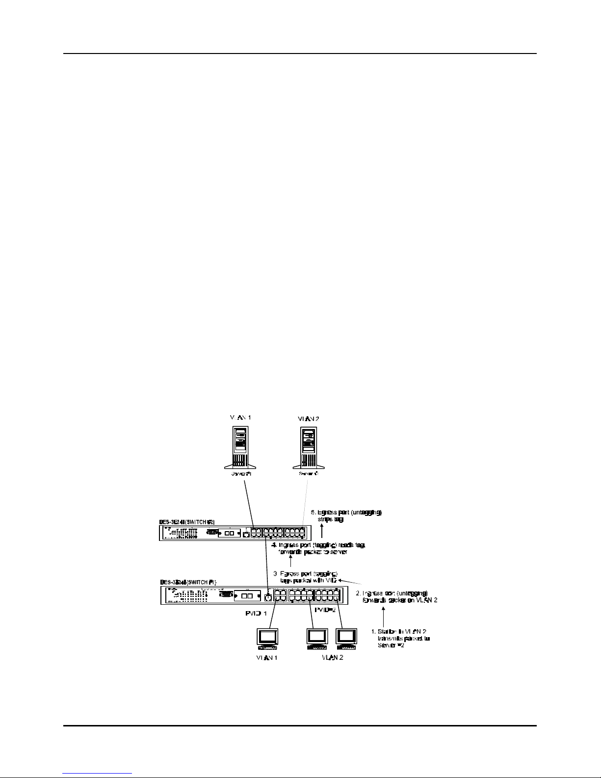
Stackable NWay Ethernet Switch User’s Guide
38 Switch Management Concepts
♦ Tagging The act of putting 802.1Q VLAN information into the header of a packet. Ports with tagging enabled will put
the VID number, priority, and other VLAN information into all packets that flow out it. If a packet has previously been
tagged, the port will not alter the packet, thus keeping the VLAN information intact. Tagging is used to send packets
from one 802.1Q -compliant device to another.
♦ Untagging The act of stripping 802.1Q VLAN information out of the packet header. Ports with untagging enabled
will take all VLAN information out of all packets that flow out of a port. If the packet doesn’t have a VLAN tag, the
port will not alter the packet, thus keeping the packet free of VLAN information. Untagging is used to send packets
from an 802.1Q -compliant switch to a non-compliant device.
♦ Ingress port A port on a switch where packets are flowing into the switch. If an ingress port has the Ingress Filter
enabled, the switch will examine each packet to determine whether or not it is a VLAN member and then take one of
two actions: if the port is not a member of a VLAN, the packet will be dropped; if the port is a member of a VLAN, then
the packet will be forwarded. Otherwise, if the Ingress Filter is disabled, then the switch will process any packet
received at this port in its normal fashion.
♦ Egress port A port on a switch where packets are flowing out of the switch, either to another switch or to an end
station, and tagging decisions must be made. If an egress port is connected to an 802.1Q-compliant switch, tagging
should be enabled so the other device can take VLAN data into account when making forwarding decisions (this allows
VLANs to span multiple switches). If an egress connection is to a non-compliant switch or end-station, tags should be
stripped so the (now normal Ethernet) packet can be read by the receiving device.
VLANs Over 802.1Q-compliant Switches
When switches maintaining the same VLANs are 802.1Q-compliant, it is possible to use tagging. Tagging puts 802.1Q
VLAN information into each packet header, enabling other 802.1Q -compliant switches that receive the packet to know how
to treat it. Upon receiving a tagged packet, an 802.1Q-compliant switch can use the information in the packet header to
maintain the integrity of VLANs, carry out priority forwarding, etc.
Data transmissions between 802.1Q -compliant switches take place as shown below.
Figure 5-5. Data transmissions between 802.1Q-compliant Switches
Page 39

Stackable NWay Ethernet Switch User’s Guide
Switch Management Concepts 39
In the above example, step 4 is the key element. Because the packet has 802.1Q VLAN data encoded in its header, the
ingress port can make VLAN-based decisions about its delivery: whether server #2 is attached to a port that is a member
of VLAN 2 and, thus, should the packet be delivered; the queuing priority to give to the packet, etc. It can also perform
these functions for VLAN 1 packets as well, and, in fact, for any tagged packet it receives regardless of the VLAN number.
If the ingress port in step 4 were connected to a non-802.1Q -compliant device and was thus receiving untagged packets, it
would tag its own PVID onto the packet and use this information to make forwarding decisions. As a result, the packets
coming from the non-compliant device would automatically be placed on the ingress ports VLAN and could only
communicate with other ports that are members of this VLAN.
Port-Based VLANs
Port-based VLANs are a simplified version of the 802.1Q VLANs described in the previous section. In port-based VLANs,
all the 802.1Q settings are pre-configured allowing you to quickly and easily setup and maintain port -based VLANs on
your network.
In port -based VLANs, broadcast, multicast and unknown packets will be limited to within the VLAN. Thus, port-based
VLANs effectively segment your network into broadcast domains. Furthermore, ports can only belong to a single VLAN.
Because port -based VLANs are uncomplicated and fairly rigid in their implementation, they are best used for network
administrators who wish to quickly and easily setup VLANs in order to isolate limit the effect of broadcast packets on
their network.
For the most secure implementation, make sure that end stations are directly connected to the switch. Attaching a hub,
switch or other repeater to the port causes all stations attached to the repeater to become members of the Port -based
VLAN.
To setup port -based VLANs, simply select one of 24 VLAN ID numbers, name the VLAN and specify which ports will be
members. All other ports will automatically be forbidden membership, even dynamically as a port can belong to only one
VLAN.
Broadcast Storms
Broadcast storms are a common problem on today’s networks. Basically, they consist of broadcast packets that flood
and/or are looped on a network causing noticeable performance degradation and, in extreme cases, network failure.
Broadcast storms can be caused by network loops, malfunctioning NICs, bad cable connections, and applications or
protocols that generate broadcast traffic, among others.
In effect, broadcast storms can originate from any number of sources, and once they are started, they can be selfperpetuating, and can even multiply the number of broadcast packets on the network over time. In the best case, network
utilization will be high and bandwidth limited until the hop counts for all broadcast packets have expired, whereupon the
packets will be discarded and the network will return to normal. In the worst case, they will multiply, eventually using up
all the network bandwidth (although network applications will usually crash long before this happens), and cause a
network meltdown.
Broadcast storms have long been a concern for network administrators with routers traditionally being used to prevent
their occurrence, and if that failed, to at least limit their scope. However, with the advent of VLANs, switches are now able
to limit broadca st domains better and cheaper than routers. Also, many switches, including the DES-3624 Series, have
broadcast sensors and filters built into each port to further control broadcast storms.
Page 40

Stackable NWay Ethernet Switch User’s Guide
40 Switch Management Concepts
Segmenting Broadcast Domains
The Switch allows you to segment broadcast domains. It does this by forwarding packets only to ports in the same
broadcast domain or VLAN. Thus, broadcast packets will only be forwarded to ports that are members of the same
broadcast domain or VLAN. Other parts of the network are effectively shielded. As a result, the smaller the broadcast
domain, the less effect a broadcast storm will have. Since VLANs and broadcast domains are implemented at each switch
port, they can be quite effective in limiting the scope of broadcast storms.
Eliminating Broadcast Storms
SNMP agents can be programmed to monitor the number of broadcast packets on switch ports and act on the data. When
the number of broadcast packets on a given port rise past an assigned threshold, an action can be triggered. When enabled,
the usual action is to block the port to broadcast frames, which discards all broadcast frames arriving at the port from the
attached segment. Not only does this isolate the broadcast domain, but it actually starts removing broadcast packets from
the affected segment. When the number of broadcast packets falls to an acceptable level (below a falling threshold), the
SNMP agent can remove the blocking condition, returning the port to its normal operational state.
In the Switch, the default rising threshold is met when more than 500 broadcast packets per second are being detected on a
specified port. Once the rising threshold is surpassed for a duration of more than 5 seconds, it will trigger the broadcast
storm rising action configured by the user. The default falling threshold is met if there are less than 250 broadcast packets
per second. It is triggered once the duration is at least 30 seconds. The actions can easily be defined by using a normal
SNMP management program or through the console interface.
Page 41

Stackable NWay Ethernet Switch User’s Guide
Using the Console Interface 41
66
6 U SING THE CONSOLE INTERFACE
Your Stackable NWay Ethernet Switch supports a console management interface that allows you to set up and control your
Switch, either with an ordinary terminal (or terminal emulator), or over the network using the TCP/IP Telnet protocol. You
can use this facility to perform many basic network management functions. In addition, the console program will allow you
to set up the Switch for management using an SNMP-based network management system. This chapter describes how to
use the console interface to access the Switch, change its settings, and monitor its operation.
Setting Up A Console
First-time configuration must be carried out through a “console,” that is, either (a) a VT100-type serial data terminal, or
(b) a computer running communications software set to emulate a VT100. The console must be connected to the
Diagnostics port. This is an RS-232 port with a 9-socket D -shell connector and DCE -type wiring. Make the connection as
follows:
1. Obtain suitable cabling for the connection.
You can use either (a) a “null-modem” RS-232 cable or (b) an ordinary RS-232 cable and a null-modem adapter. One end
of the cable (or cable/adapter combination) must have a 9-pin D-shell connector suitable for the Diagnostics port; the
other end must have a connector suitable for the console’s serial communications port.
2. Power down the devices, attach the cable (or cable/adapter combination) to the correct ports, and restore power.
3. Set the console to use the following communication parameters for your terminal:
♦ 9600 baud
♦ No parity checking (sometimes referred to as “no parity”)
♦ 8 data bits (sometimes called a “word length” of 8 bits)
♦ 1 stop bit (sometimes referred to as a 1-bit stop interval)
♦ VT-100/ANSI compatible
♦ Arrow keys enabled
A typical console connection is illustrated below:
Page 42

Stackable NWay Ethernet Switch User’s Guide
42 Using the Console Interface
Figure 6-1. Example of a console connection
Connecting to the Switch Using Telnet
Once you have set an IP address for your Switch, you can use a Telnet program (in a VT -100 compatible terminal mode) to
access and control the Switch. Most of the screens are identical, whether accessed from the console port or from a Telnet
interface. You can also use a Web-based browser to manage the Switch. See the next chapter, “Web-Based Network
Management,” for further information.
Console Usage Conventions
The console interface makes use of the following conventions:
1. Items in <angle brackets> can be toggled on or off using the space bar.
2. Items in [square brackets] can be changed by typing in a new value. You can use the backspace and delete keys to
erase characters behind and in front of the cursor.
3. The up and down arrow keys, the left and right arrow keys, the Tab key and the Backspace key, can be used to move
between selected items. It is recommended that you use the tab key and backspace key for moving around the
console.
4. Items in UPPERCASE are commands. Moving the selection to a command and pressing <Enter> will execute that
command, e.g., SAVE or EXIT.
Please note that the command APPLY only applies for the current session. Use Save Changes from the main menu for
permanent changes. An asterisk “*” indicates a change has been made but won’t take effect until the Switch has been
rebooted.
First Time Connecting To The Switch
The Switch supports user-based security that can allow you to prevent unauthorized users from accessing the Switch or
changing its settings. This section tells how to log onto the Switch.
Note: The passwords used to access the Switch are case sensitive; therefore, “S” is not the same as “s.”
When you first connect to the Switch, you will be presented with th e first login screen (shown below). Press Ctrl+R (hold
down the Ctrl key, press the R key, and release both keys) to call up the screen, if the initial login screen does not
appear. Also Ctrl+R can be used at any time to refresh the screen.
Page 43
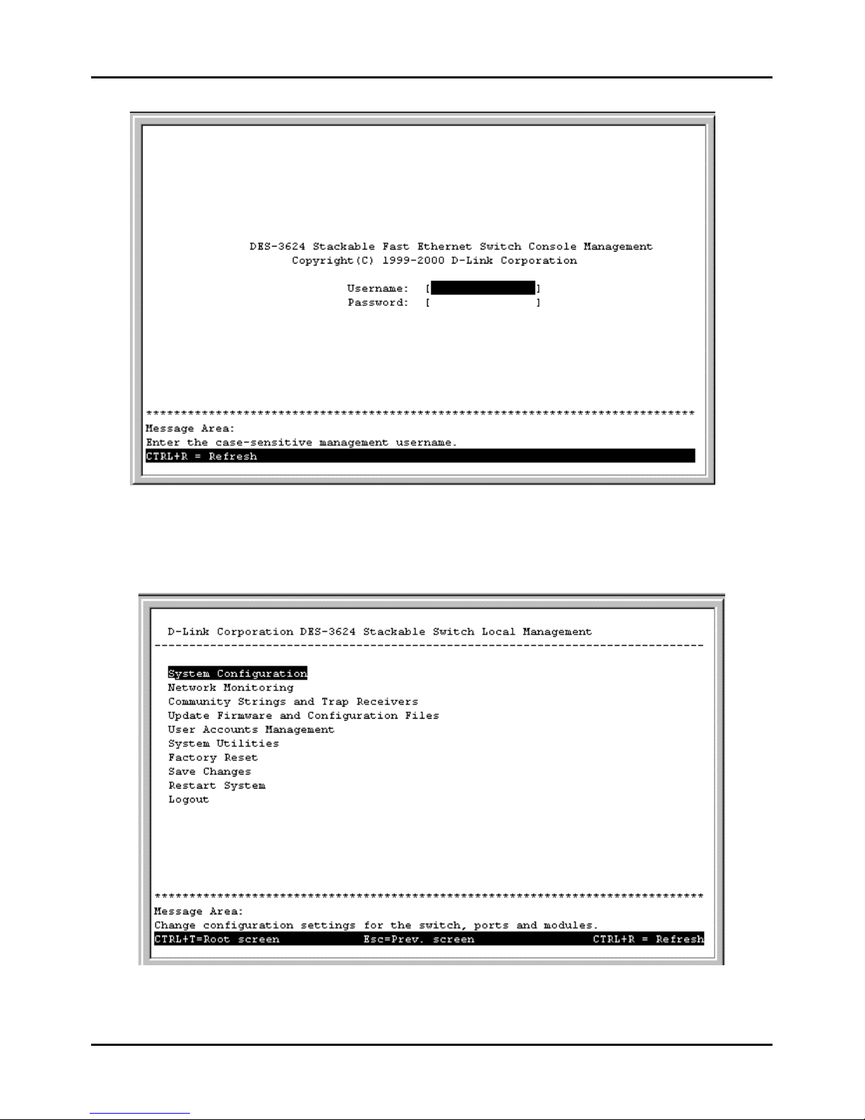
Stackable NWay Ethernet Switch User’s Guide
Using the Console Interface 43
Figure 6-2. Initial Screen, first time connecting to the Switch
Note: There is no initial username or password. Leave the username and password fields blank.
Press <Enter> or <Return> in the username and password fields. You will be given access to the main menu show n below:
Figure 6-3. Main Menu
Page 44

Stackable NWay Ethernet Switch User’s Guide
44 Using the Console Interface
The first user automatically gets Administrator privileges (See Table 6-1). It is recommended to create at least one
Administrator-level user for the Switch.
User Accounts Management
From the screen above, move the cursor to the User Accounts Management menu and press <Enter>, then the Users
Accounts Management menu appears.
1. Choose Create/Modify User Accounts from the User Accounts Management menu and the Add/Modify
User Accounts menu appears.
2. Enter the new user name, assign an initial password, and then confirm the new password. Determine whether the new
user should have Administrator or Normal User privileges. (Use the space bar to toggle between the two options).
3. Press APPLY to let the user addition take effect.
4. Press <Esc> to return to the previous screen or Ctrl+T to go to the root screen.
5. To see a listing of all user accounts and access levels, press <Esc>. Then choose User Accounts Control Table.
The User Accounts Control Table screen appears.
Administrator and Normal User Privileges
There are two levels of user privileges: Administrator and Normal User. Some menu selections available to users with
Administrator privileges may not be available to Normal Users. The main menus shown are the menus for the two types
of users:
The following table summarizes Administrator and Normal User privileges:
Menu Administrator Normal User
Privilege
Configuration Yes Yes, view only.
Network Monitoring Yes Yes, view only.
Community Strings and Trap Stations Yes Yes, view only.
Update Firmware and Configuration
Files
Yes Yes, view only.
User Accounts Management
Create/Modify User Accounts Yes Yes, view only.
View/ Delete User Accounts Yes Yes, view only.
System Utilities Yes Yes, (Ping Test);
view only for the
rest.
Factory Reset Yes No
Restart System Yes No
Table 6-1. Administrator and Normal User Privileges
After establishing a User Account with Administrator-level privileges, press <Esc> twice. Then choose the Save
Changes menu (see below). Pressing any key will return to the main menu. You are now ready to operate the Switch.
Page 45

Stackable NWay Ethernet Switch User’s Guide
Using the Console Interface 45
Save Changes
The Switch has two levels of memory normal RAM and non-volatile or NV-RAM. Settings need to be changed in all screens
by pressing Ctrl + S. When this is done, the settings will be immediately applied to the switching software in RAM, and
will immediately take effect. Some settings, though, require you to restart the Switch before they will take effect.
Restarting the Switch will erase all settings in RAM and reload them from the NV-RAM. Thus, it is necessary to save all
settings to the NV-RAM before restarting the Switch.
In order to retain any modifications made in the current session, it is necessary to choose Save Changes from the main
menu. The following screen will appear to indicate your new settings have been processed:
Figure 6-4. Save Changes screen
After the settings have been saved to NV -RAM, they will become the default settings for the Switch, and they will be used
every time it is powered on, reset or rebooted. The only exception to this is a factory reset, which will clear all settings and
restore them to their initial values listed in Appendix D, which were present when the Switch was purchased.
Login On The Switch Console By Registered Users
To log in once you have created a registered user,
1. Type in your username and press <Enter>.
2. Type in your password and press <Enter>.
3. The main menu screen will be displayed based on your Administrator or Normal User access level or privilege.
Create/Modify User Accounts
To add or change your user password:
Page 46
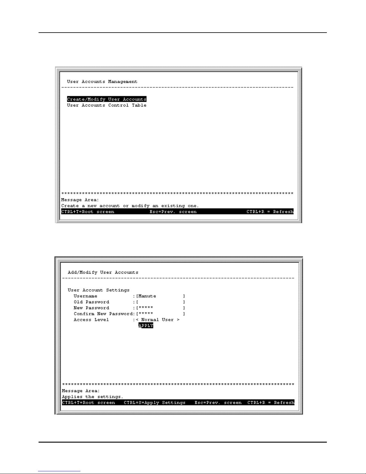
Stackable NWay Ethernet Switch User’s Guide
46 Using the Console Interface
1. Choose Users Accounts Management from the main menu. The following User Accounts Management
menu appears:
Figure 6-5. User Accounts Management menu
2. Choose Create/Modify User Accounts. The following screen appears:
Figure 6-6. Add/Modify User Accounts screen
Page 47
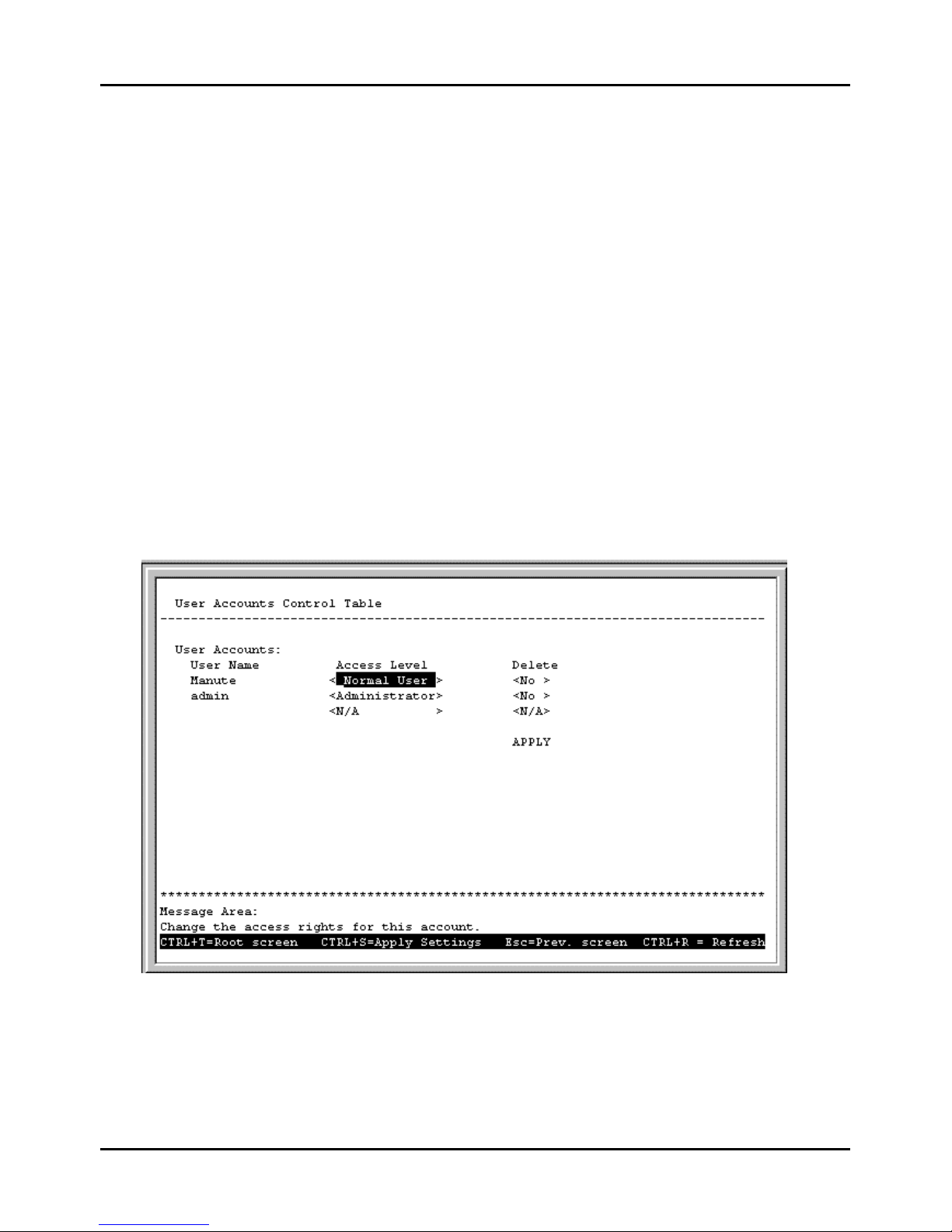
Stackable NWay Ethernet Switch User’s Guide
Using the Console Interface 47
3. Type in your Username and press <Enter>.
4. If you are an old user, type in the Old Password and press <Enter>.
5. Type in the New Password you have chosen, and press <Enter>. Type in the same new password in the following
field to verify that you have not mistyped it.
6. Determine whether the new user should have Normal User or Administrator privileges.
7. Choose the APPLY command to let the password change take effect.
This method can also be used by an Administrator-level user to change another user’s password.
User Accounts Control Table
Access to the console, whether using the console port or via Telnet, is controlled using a user name and password. Up to
three of these user names can be defined. The console interface will not let you delete the current logged-in user, however, in
order to prevent accidentally deleting all of the users with Administrator privilege.
Only users with the Administrator privilege can delete users.
To view a user account:
Choose User Accounts Control Table from the User Accounts Management menu. The following screen
appear s:
Figure 6-7. User Accounts Control Table screen
To delete your user password:
1. Toggle the Delete field of the user you wish to remove to Yes.
2. Press APPLY to let the user deletion take effect.
Page 48
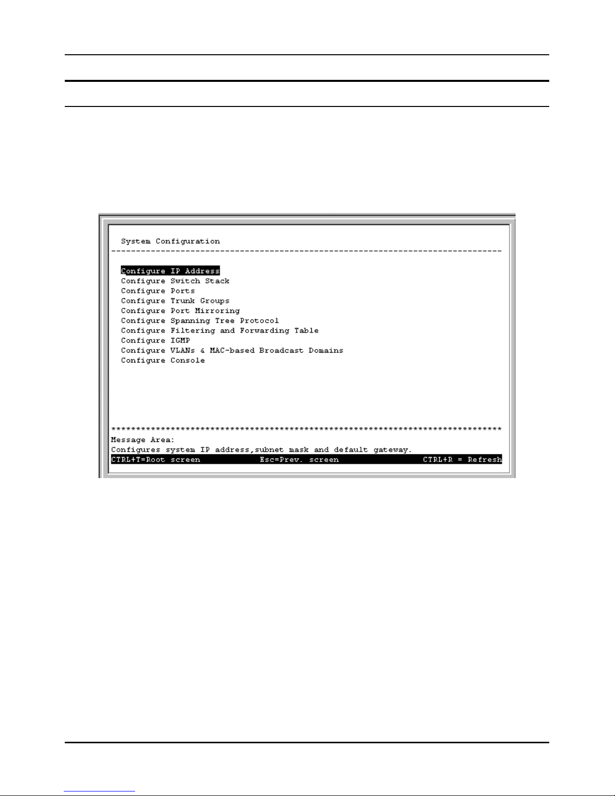
Stackable NWay Ethernet Switch User’s Guide
48 Using the Console Interface
Setting Up The Switch
This section will help prepare the Switch user by describing the System Configuration, Update Firmware and
Configuration Files , Save Changes, and System Utilities menus and their respective sub-menus.
System Configuration
Choose System Configuration to access the first item of the Switch’s main menu. The following menu appears:
Figure 6-8. System Configuration menu
You will need to change some settings to allow you to be able to manage the Switch from an SNMP-based Network
Management System such as SNMP v1 or to be able to access the Switch using the Telnet protocol. See the next chapter for
Web-based network management information.
Configure IP Address
The Switch needs to have a TCP/IP address assigned to it so that an in -band network management system or Telnet client
can find it on the network. The IP Address Configuration screen allows you to change the settings for the two different
interfaces used on the Switch: the Ethernet interface used for in -band communication, and the SLIP interface used over the
console port for out-of-band communication.
Choose Configure IP Address to access the first item on the System Configuration menu. The following screen
appears:
Page 49
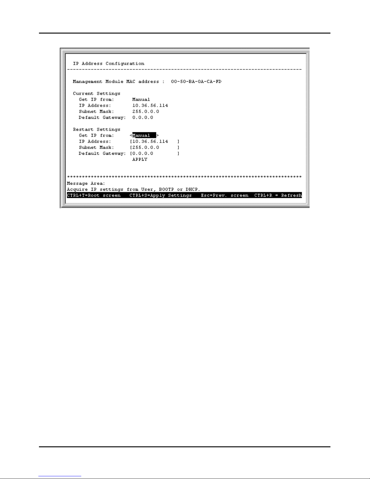
Stackable NWay Ethernet Switch User’s Guide
Using the Console Interface 49
Figure 6-9. IP Address Configuration screen
The fields listed under the Current Settings heading are those that are presently being used by the Switch. Those fields
listed under the Restart Settings heading will be used after th e Switch has been reset. Fields that can be set include:
♦ Get IP from Determines whether the Switch should get its IP Address settings from the user (Manual), a
BOOTP server, or a DHCP server. If Manual is chosen, the Switch will use the IP Address, Subnet Mask and
Default Gateway settings defined in this screen upon being rebooted. If BOOTP is chosen, the Switch will send out
a BOOTP broadcast request when it is powered up. The BOOTP protocol allows IP addresses, network masks, and
default gateways to be assigned by a central BOOTP server. If this option is set, the Switch will first look for a
BOOTP server to provide it with this information before using the supplied settings. If DHCP is chosen, a Dynamic
Host Configuration Protocol request will be sent when the Switch is powered up.
♦ IP Address Determines the IP address used by the Switch for receiving SNMP and Telnet communications. These
fields should be of the form xxx.xxx.xxx.xxx, where each xxx is a number (represented in decimal) between 0 and
255. This address should be a unique address on a network assigned to you by the central Internet authorities. The
same IP address is shared by both the SLIP and Ethernet network interfaces.
♦ Subnet Mask Bitmask that determines the extent of the subnet that the Switch is on. Should be of the form
xxx.xxx.xxx.xxx, where each xxx is a number (represented in decimal) between 0 and 255. If no subnetting is being
done, the value should be 255.0.0.0 for a Class A network, 255.255.0.0 for a Class B network, and 255.255.255.0 for
a Class C network.
♦ Default Gateway IP address that determines where frames with a destination outside the current subnet
should be sent. This is usually the address of a router or a host acting as an IP gateway. If your network is not part
of an internetwork, or you do not want the Switch to be accessible outside your local network, you can leave this field
blank.
Configure Console
You can use the Console Options screen to choose whether to use the Switch’s RS-232C serial port for console
management or for out -of-band TCP/IP communications using SLIP, and to set the bit rate used for SLIP communications.
Page 50
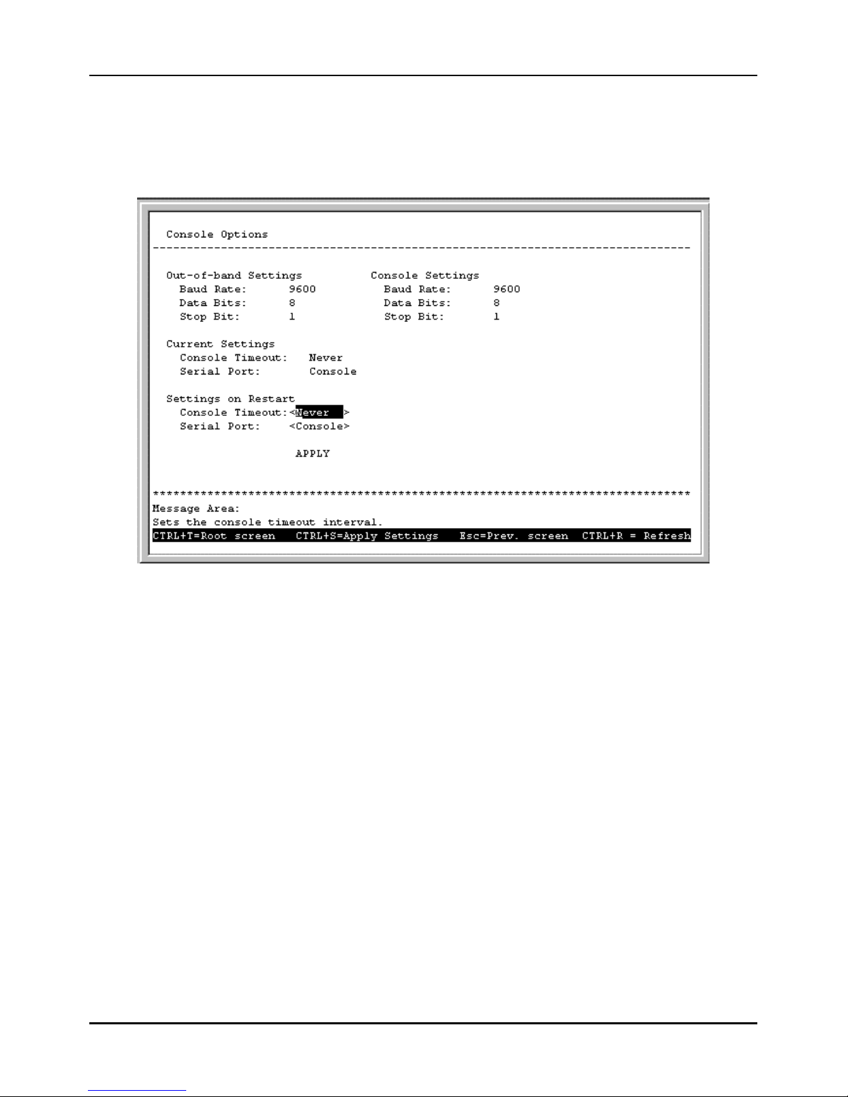
Stackable NWay Ethernet Switch User’s Guide
50 Using the Console Interface
Note that the DES-3624i/DES-3624iF/DES-3624iFM has an RS-232C serial port but the DES -3624/DES-3624F/DES3624FM does not.
Choose Configure Console to access the last item on the System Configuration menu. The following screen
appears:
Figure 6-10. Console Options screen
The following fields can be set:
Settings on Restart:
♦ Console Timeout This setting for the restart of the console is 2 mins, 5 mins, 10 mins, 15 mins, or Never.
♦ Serial Port Determines whether the serial port should be used for out-of-band (SLIP) management or for console
management, starting from the next time the Switch is restarted. In this field, you can toggle between SLIP or
Console port type settings.
♦ Baud Rate Determines the serial port bit rate that will be used the next time the Switch is restarted. Applies
only when the seri al port is being used for out-of-band (SLIP) management; it does not apply when the port is used
for the console port. Available speeds are: 2400, 9600, 19200 and 38400 bits per second. The default setting in this
Switch version is 9600.
The top of the screen displays the current settings for Console Timeout and Serial Port as well as the Baud Rate, Data
Bits, and Stop Bit for Out of Band and Console settings, respectively.
Configure Switch Stack
The Switch Stack Configuration screen shows various pieces of information about your Switch, and allows you to set
the System Name, System Location, and System Contact . These settings can be retrieved from the Switch using SNMP
requests, allowing these settings to be used for network management purposes.
Page 51
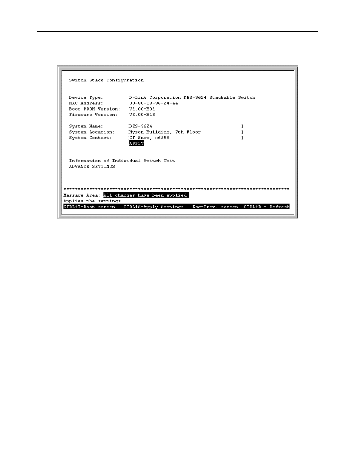
Stackable NWay Ethernet Switch User’s Guide
Using the Console Interface 51
Choose Configure Switch Stack to access the second item on the System Configuration menu. The following
screen appears:
Figure 6-11. Switch Stack Configuration screen
The fields you can set are:
♦ System Name Corresponds to the SNMP MIB II variable system.sysName, and is used to give a name to
the Switch for administrative purposes. The Switch’s fully qualified domain name is often used, provided a name
has been assigned.
♦ System Location Corresponds to the SNMP MIB II variable system.sysLocation, and is used to
indicate the physical location of the Sw itch for administrative purposes.
♦ System Contact Corresponds to the SNMP MIB II variable sysContact, and is used to give the name and
contact information for the person responsible for administering the Switch.
Information of Individual Switch Unit
This screen allows you to view information for each Switch in your stack, including the Module, Type, and Hardware
Version. Press Information of Individual Switch Unit on the Switch Stack Configuration screen to access the
Information of Individual Switch Unit screen:
Page 52
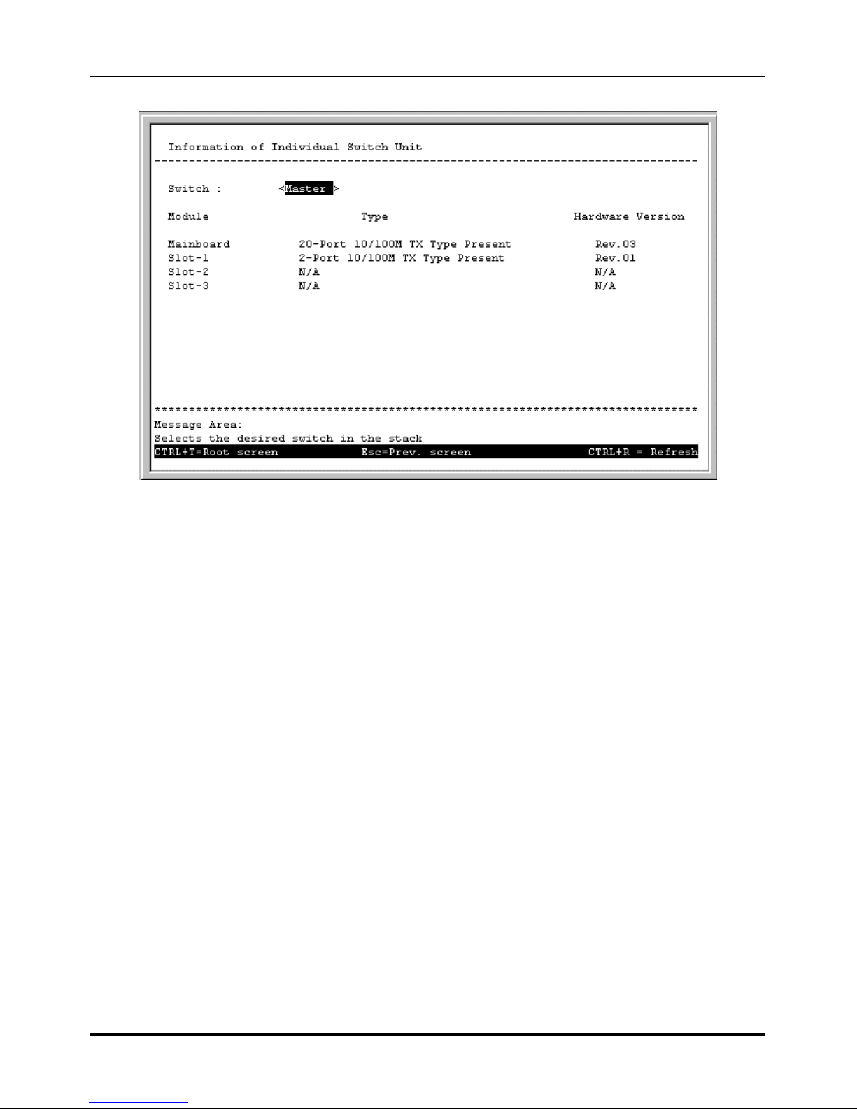
Stackable NWay Ethernet Switch User’s Guide
52 Using the Console Interface
Figure 6-12. Information of Individual Switch Unit screen
Use the space bar to select the desired Switch in your stack.
Advance Settings
The Configure Advanced Switch Stack Features screen allows you to set an expiration time for MAC address
entries and enable or disable auto-partitioning on all ports. Press ADVANCE SETTINGS on the Switch Stack
Configuration screen to access the Configure Advanced Switch Stack Features screen:
Page 53
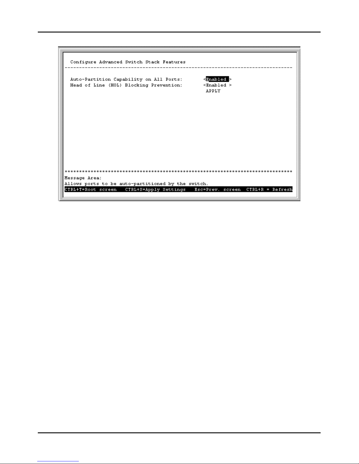
Stackable NWay Ethernet Switch User’s Guide
Using the Console Interface 53
Figure 6-13. Configure Advanced Switch Stack Features screen
The fields you can set are:
♦ Auto-Partition Capability on All Ports When this function is enabled, if too many consecutive collisions occur
on an individual port, the port will be blocked off until a good packet is seen on the wire. If a port is partitioned, the
Switch can only transmit data, not receive it.
♦ Head Of Line (HOL) Blocking Prevention Enables or disables Head-Of-Line Blocking Prevention. Head-of
Line blocking occurs when a packet originating on Port 1, for instance, needs to be forwarded to Ports 2 and 3. If Port 2
is occupied (causing the packet to be held in memory until the port is free), the packet destined for Port 3 will also be
delayed, even though the port may be free. Cumulatively, these delays can have a noticeable effect on overall network
performance. Enabling HOL Blocking Prevention prevents Head-of-Line blocking from occurring, meaning that the
packet destined for Port 3 gets delivered immediately.
Configure Port
The port configuration screen allows you to change the port state in the case when you would like to partition a port due to
excessive collision, or for observation, device repair, or security reasons. Great caution, however, must be observed when
partitioning a port; you should make sure that the partitioned port is not being used as the port to control or monitor the
condition of other devices.
Page 54
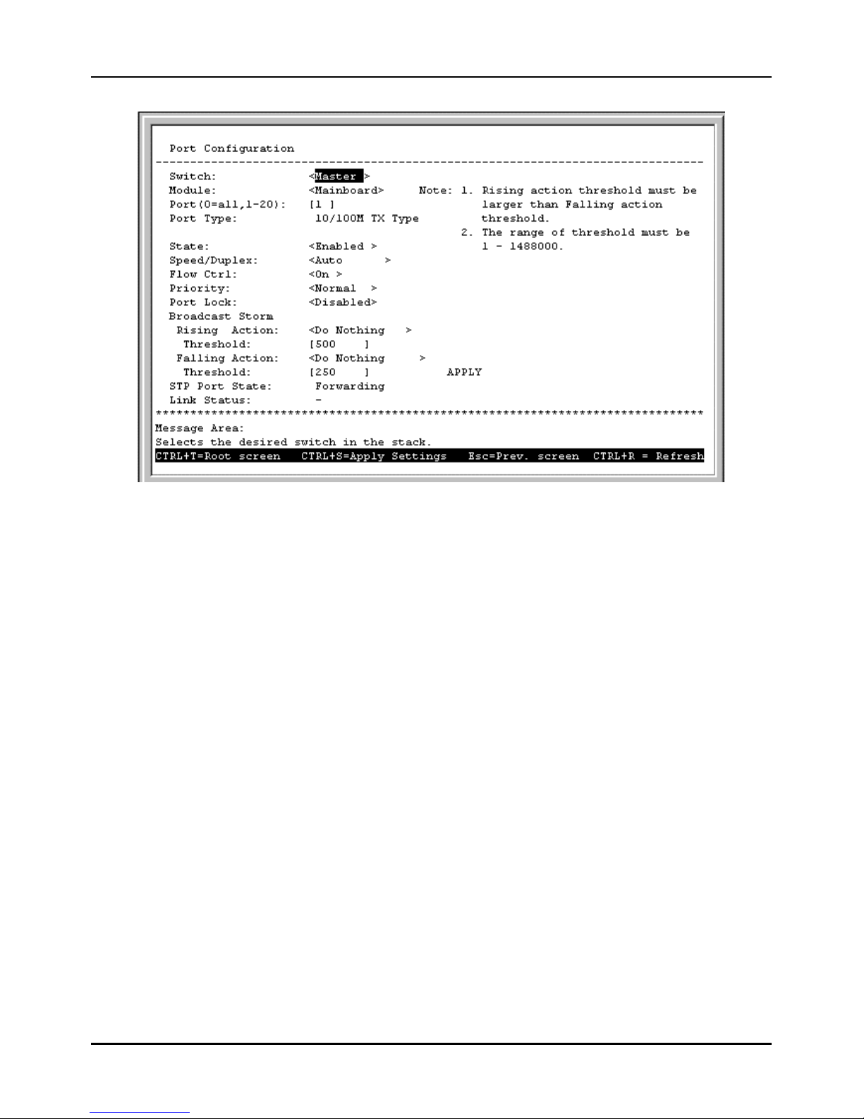
Stackable NWay Ethernet Switch User’s Guide
54 Using the Console Interface
Figure 6-14. Port Configuration screen
Items in the above window are defined as follows:
♦ Switch Specifies the Switch where the port is being configured.
♦ Module Specifies the module where the port is being configured.
♦ Port Specifies the port that will be configured.
♦ Port Type Specifies the speed and cable type of the selected port.
♦ State Enables or Disables the port. This amounts to turning the port on or off.
♦ Speed/Duplex Selects the desired Speed and Duplex settings for the port. Possibilities include: Auto,
100M/Full, 100M/Half, 10M/Full, or 10M/Half. If a Gigabit module is being used, 1000M/Full will be
displayed in this field. Choosing Auto enables NWay auto-configuration on the port.
♦ Flow Ctrl Toggles flow control On or Off. It is useful during periods of heavy network activity when the Switch’s
bu ffers can receive too much traffic and fill up faster than the Switch can forward the information. In such cases, the
Switch will intervene and tell the transmitting device to pause to allow the information in the port buffer to be sent.
Confirm that Flow Control is in force by checking the Status field.
♦ Priority Selects Normal, High or Low. The Switch has two packet queues where incoming packets wait to be
processed for forwarding; a high priority and low priority queue. The high priority queue should only be used for data
in which latency can have adverse affects on the function of an application, such as video or audio data, where
latency can produce distorted sounds and images. Packets in the low priority queue will not be processed unless the
High priority queue is empty. Setting the port priority to High will deliver all packets arriving at the port to the
high priority queue, a Low setting will send them all to the low priority queue. The Normal setting causes the port
to examine the packet for an IEEE 802.1p/q priority tag. If no tag exists, the packet will be sent to the low priority
queue. If the priority tag field in the packet header contains a value of 0-3, the packet will be placed in the low
priority queue; a value of 4-7 causes the packet to be placed in the high priority queue.
Page 55

Stackable NWay Ethernet Switch User’s Guide
Using the Console Interface 55
♦ Port Lock When Enabled, automatic learning for all stations connected to this port will stop and entries in the
Forwarding Table for all devices residing on this port will age out. The only traffic this port will allow is traffic from
machines whose MAC address is manually entered in the Static Forwarding Table.
♦ Broadcast Storm Rising Action This setting will be activated when a Broadcast Storm Rising Threshold is
met. When triggered, the port can be configured to Do Nothing, Block, or Block & Trap. The Do Nothing setting
causes the switch to operate normally, in other words, ignore the broadcast storm condition. The Block setting
causes the port to drop all broadcast frames, thus isolating the broadcast storm. Block & Trap performs the same
action as Block, except it also sends a trap to the designated Trap Recipient informing them of the situation. For
more information on broadcast storms, please refer to the previous chapter.
♦ Broadcast Storm Rising Action Threshold This setting defines a ceiling for the number of broadcast
packets per second on this port. Once met, the Broadcast Storm Rising Action (above) will be triggered. The
assigned number should be high enough to allow normal broadcast packets (which comprise significant traffic) to be
let through, while being low enough so that broadcast storms can be detected early. The Rising Threshold can be
from 1 to 1488000, with 500 the default.
♦ Broadcast Storm Falling Action This setting will be activated when the Broadcast Storm Rising Threshold
and then the Broadcast Storm Falling Threshold are each met. This setting can be configured to Do Nothing,
Forward, or Forward & Trap. The Do Nothing setting causes the switch to operate normally, that is, to ignore
the situation. If the port had met the Broadcast Storm Rising Action criteria and started Blocking broadcast
packets, it will continue doing so. The Forwarding setting causes the port to begin forwarding broadcast frames,
thus removing the Blocking state imposed by the Broadcast Storm Rising Action. Forward & Trap performs
the same action as Forward, except it also sends a trap to the designated Trap Recipient informing them of the
situation.
♦ Broadcast Storm Falling Action Threshold This setting defines the number of broadcast packets per
second on this port which will trigger the Broadcast Storm Falling Action (above). This threshold will only trigger
an action if the Broadcast Storm Rising Threshold has first been reached. The assigned number should be high
enough to allow normal broadcast packets (which comprise significant traffic) to be let through as early as possible,
while being low enough so that broadcast storms are completely eliminated. The Falling Threshold can be from 1 to
1488000, with 250 the default.
Press CTRL+S to let the changes take effect. If you wish these changes to be the default for the switch, return to the
main menu and choose Save Changes.
STP Port State (whether the Spanning Tree Protocol is enabled or disabled on this port) and Link Status reflect the
current conditions of the port. They are read-only fields and cannot be changed.
Configure Trunk Groups
Ports on the Switch can be grouped together in a single logical port called a trunk. This is discussed in detail in the Port
Trunking section of the “Switch Management Concepts” chapter of this manual.
To set up a trunk group, choose Configure Trunk Groups on the System Configuration menu. The following
screen appears:
Page 56
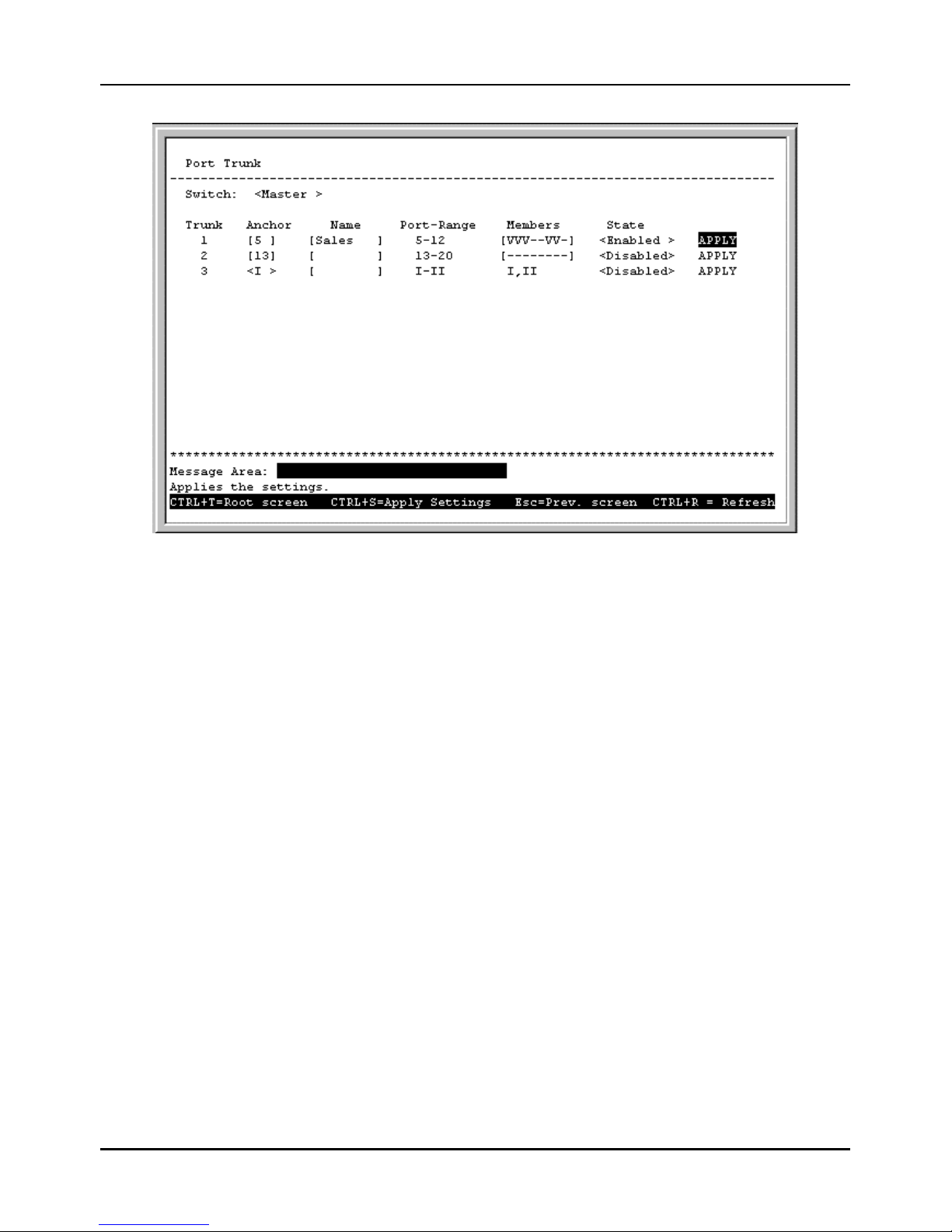
Stackable NWay Ethernet Switch User’s Guide
56 Using the Console Interface
Figure 6-15. Port Trunk screen
The fields you can set are:
♦ Anchor There are either two or three listings representing the anchor port for each of the three trunk groups
available on the Switch (the third listing will only be displayed if an optional two-port plug-in module is being used).
The anchor port must fall within the port range and be included as a member port.
♦ Name Enter the desired group name. In the example pictured above the first trunk group designates a trunk group
named Sales.
♦ Members Select between 2 to 8 ports in the first two entries for this field. The number of ports defined here start
from the anchor port. Thus, in the example pictured above containing 5 ports in the first trunk, the ports in the trunk
group will include ports (anchor), 5, 6,7, 10, and 11. The third entry (used for 2-port front-panel modules) has a
permanent setting of 2 ports.
♦ State Enabled, Disabled or Clear. Be careful when clearing trunk groups as the connections will return to normal
operation and may cause signal loops.
Port Range is a read-only field which lists the possible ports in a selected trunk.
Press APPLY to let the changes take effect.
Configure Port Mirroring
The Switch allows you to copy frames transmitted and received on a port and redirect the copies to another port. You can
attach a monitoring device to the mirrored port, such as a sniffer or an RMON probe, to view details about the packets
passing through the first port. This is useful for network monitoring and troubleshooting purposes.
Choose Configure Port Mirroring on the System Configuration menu to access the following screen:
Page 57
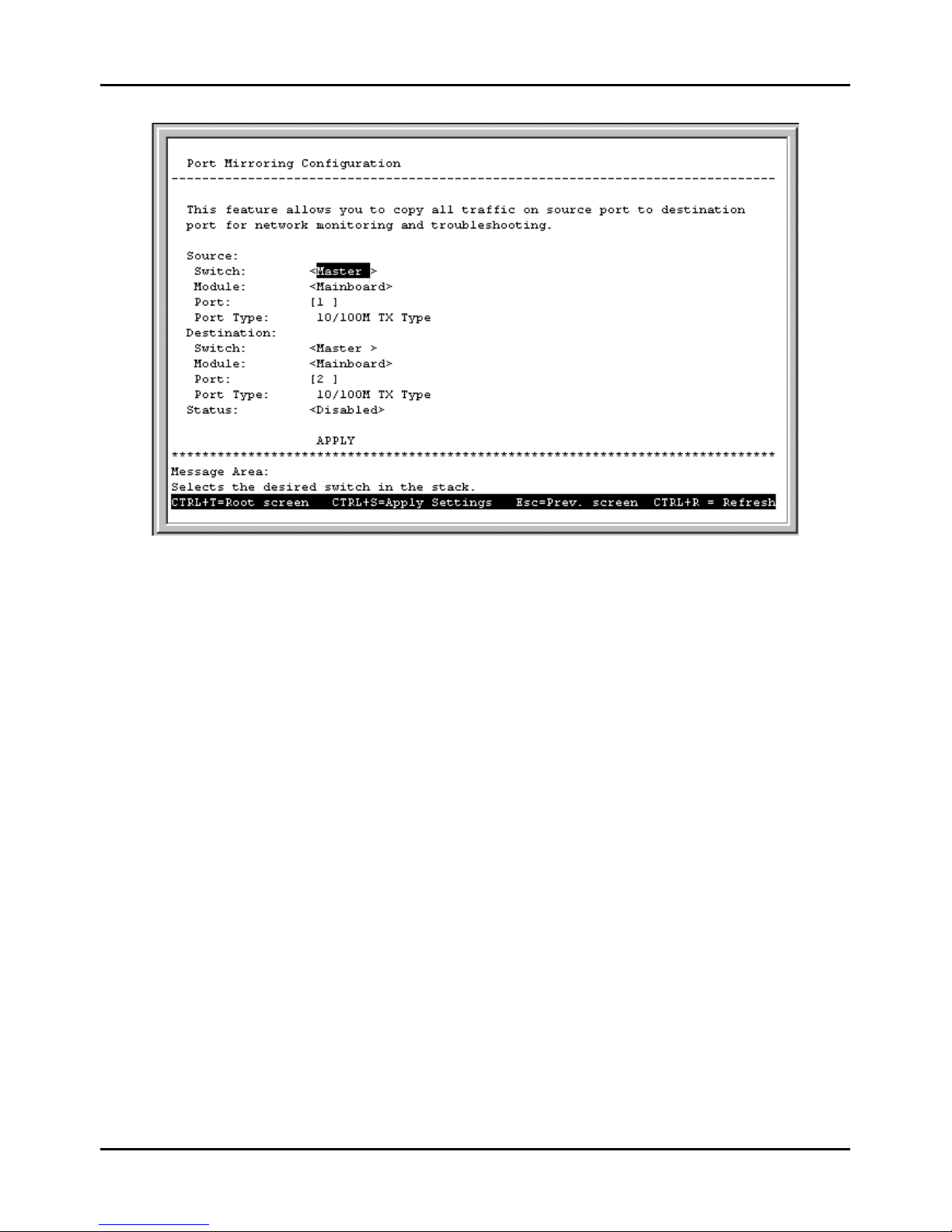
Stackable NWay Ethernet Switch User’s Guide
Using the Console Interface 57
Figure 6-16. Port Mirroring Configuration screen
To configure a mirror port, select the Switch, Module, and Port from where you want to copy frames in the Source fields.
Then select the Switch, Module, and Port which receive the copies from the source port in the Destination fields. The
destination (or target) port is where you will connect a monitoring/troubleshooting device such as a sniffer or an RMON
probe.
Note: You cannot mirror a fast port onto a slower port. For example, if you try to mirror the traffic from a 100 Mbps port
onto a 10 Mbps port, this can cause throughput problems. The port you are copying frames from should always
support an equal or lower speed than the port to which you are sending the copies. Also, the target port cannot be a
member of a trunk group.
Configure Spanning Tree Protocol
The Spanning Tree Algorithm Parameters can be used for creating alternative paths in your network. The Protocol
Parameters allow you to change the behind the scene parameters of the Spanning Tree Algorithm at the bridge level. The
parameters for this section have been fully explained in the previous chapter. It is recommended that you read this, as well
as the introductory section in the same chapter entitled Spanning Tree Algorithm, before changing any of the
parameters.
STP Parameter Settings
To change the Protocol Parameters:
1. Choose Configure Spanning Tree Protocol from the System Configuration menu. The following
Configure Spanning Tree Protocol menu will be displayed:
Page 58
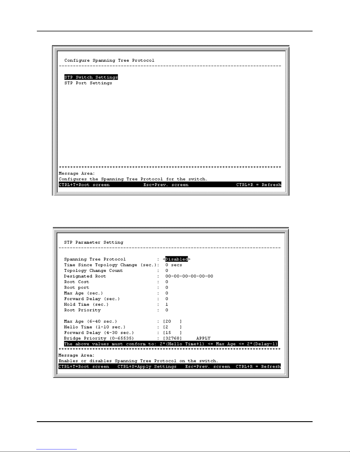
Stackable NWay Ethernet Switch User’s Guide
58 Using the Console Interface
Figure 6-17. Configure Spanning Tree Protocol menu
2. Choose STP Parameter Setting to access the following screen:
Figure 6-18. STP Parameter Setting screen
3. Change the Disabled setting to Enabled in the Spanning Tree Protocol field.
Page 59

Stackable NWay Ethernet Switch User’s Guide
Using the Console Interface 59
4. Enter the Bridge Max Age in the Max Age (6-40 sec.) field.
5. Enter the Bridge Hello Time in the Hello Time (1-10 sec.) field.
6. Enter the Bridge Forward Delay time in the Forward Delay (4-30 sec.) field.
7. Enter the Bridge Priority in the Bridge Priority (0–65535) field.
The information on the screen is described as follows:
♦ Spanning Tree Protocol Select Enabled to implement the Spanning Tree Protocol.
♦ Time Since Topology Change (sec.) Read-only object displays the last time changes were made to the
network topology. These changes usually occur when backup paths are activated due to primary path failures.
♦ Topology Change Count Read-only object displays the number of times (since the current management
session with the device was started) changes were made to the network topology. Changes usually occur on the
network when backup paths are activated.
♦ Designated Root Read-only object displays the MAC (Ethernet) address of the bridge/switch on the network
that has been chosen as the STP root.
♦ Root Cost Read-only object displays the cost for the path between the switch and the root bridge. If the switch
is the root bridge, then the root cost is zero.
♦ Root port Read-only object identifies the port (on the bridge) that offers the least path cost from the bridge to
the root bridge. In the event of a network loop, data packets will pass through the root port.
♦ Max Age (sec.) Read-only object indicates the maximum age of STP information learned from the network (on
any port) before it is discarded.
♦ Forward Delay (sec.) Read-only object indicates how fast any port on the bridge can change its spanning
state when moving towards the forwarding state. The value determines how long the port stays in each of the
listening and learning states, w hich precede the forwarding state.
♦ Hold Time (sec.) Read-only object displays the time interval during which no more than two configuration BPDUs
shall be transmitted by the bridge.
♦ Root Priority Read-only object displays the priority number of the root bridge of the Spanning Tree. The
value is used in conjunction with the bridge MAC address to set the bridge ID, which in turn is used when
determining the root bridge of a multibridged network. The root bridge is responsible for processing data packets
when network loops occur. The smaller the number set, the higher the bridge priority is. The higher the bridge
priority, the more chance the bridge has of becoming the root bridge. A bridge priority ranges from 0 to 65535,
with 0 being the highest priority.
♦ Max Age (6-40 sec.) Maximum Age is a read-write object that can be set from 6 to 40 seconds. At the end of
the Maximum Age, if a BPDU has still not been received from the Root ridge, your Switch will start sending its
own BPDU to all other switches for permission to become the Root Bridge. If it turns out that your Switch has the
lowest Bridge Identifier, it will become the Root Bridge.
♦ Hello Time (1-10 sec.) Hello Time is a read-write object that can be set from 1 to 10 seconds. This is the
interval between two transmissions of BPDU packets sent by the Root Bridge to tell all other switches that it is
indeed the Root Bridge. If you set a Hello Time for your Switch, and it is not the Root Bridge, the set Hello Time
will be used if and when your Switch becomes the Root Bridge.
♦ Forward Delay (4-30 sec.) The Forward Delay is a read-write object that can be set from 4 to 30 seconds.
This is the time any port on the Switch spends in the listening state while moving from the blocking state to the
forwarding state.
Page 60
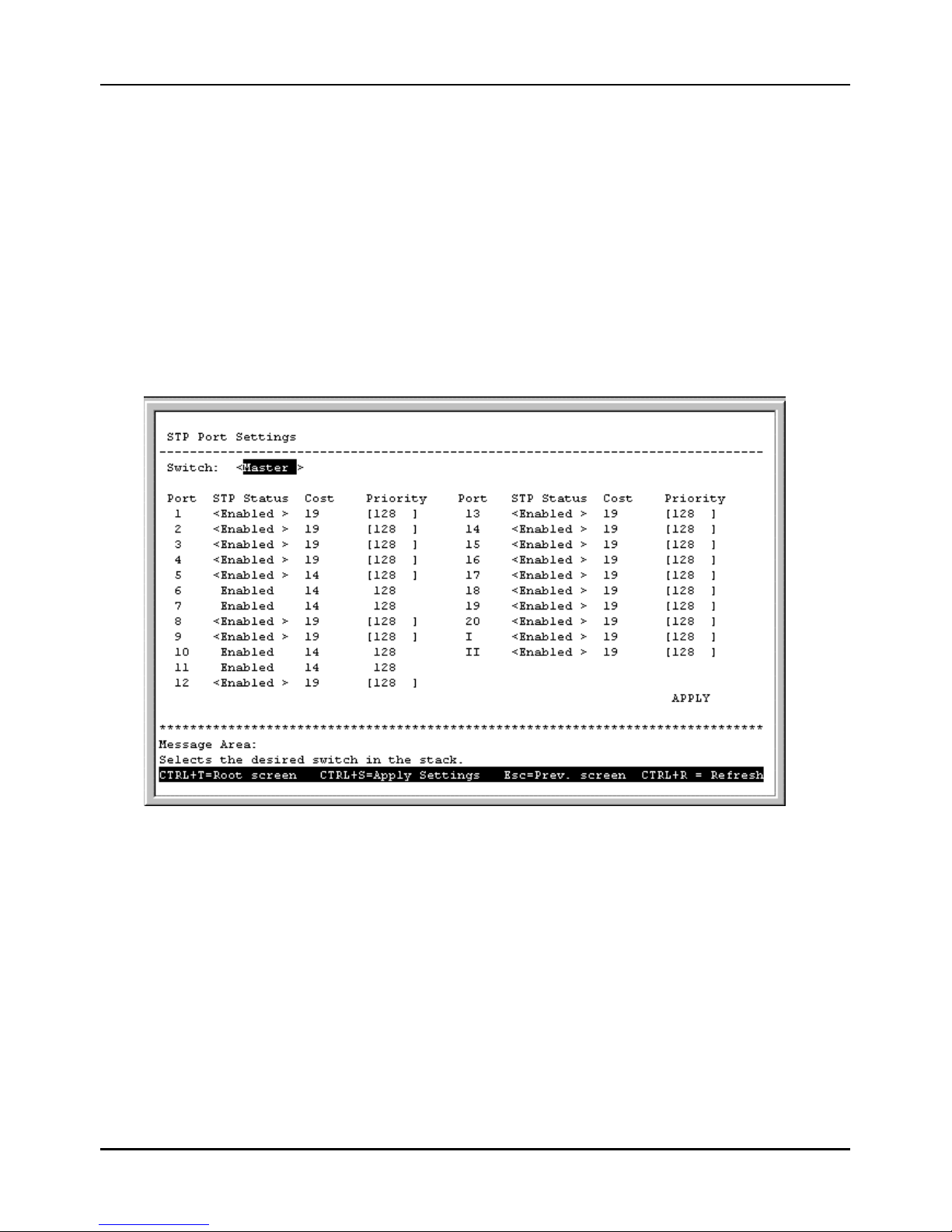
Stackable NWay Ethernet Switch User’s Guide
60 Using the Console Interface
♦ Bridge Priority (0–65535) A Bridge Priority is a read-write object that can be set from 0 to 65535. This is
the priority number of the bridge. The value is used in conjunction with the bridge MAC address to set the bridge
ID, which in tu rn is used when determining the root bridge of a multibridged network. The root bridge is
responsible for processing data packets when network loops occur. The smaller the number set, the higher the
bridge priority is. The higher the bridge priority, the more chance the bridge has of becoming the root bridge. Zero
is the highest priority.
STP Custom Settings
To change the parameters on individual ports:
1. Choose Configure Spanning Tree Protocol from the System Configuration menu.
2. Choose STP Port Settings from the Configure Spanning Tree Protocol menu. The following screen
appears:
Figure 6-19. STP Port Settings screen
Items in the above window are described as follows:
♦ STP Status Sets the Spanning Tree Protocol on a particular port to Enabled or Disabled.
♦ Cost Defines the cost for the connection.
♦ Priority Port Priority is a read-write object that can be set from 0 to 255. This is the priority number of the
port. The higher the port priority, the more chance the bridge has of becoming the root port. Zero is the highest
priority.
Note: If a port is a member of a trunk group but is not the anchor, the items shown in the above table will be read-
only and the values will be the same as those for the anchor port.
Page 61
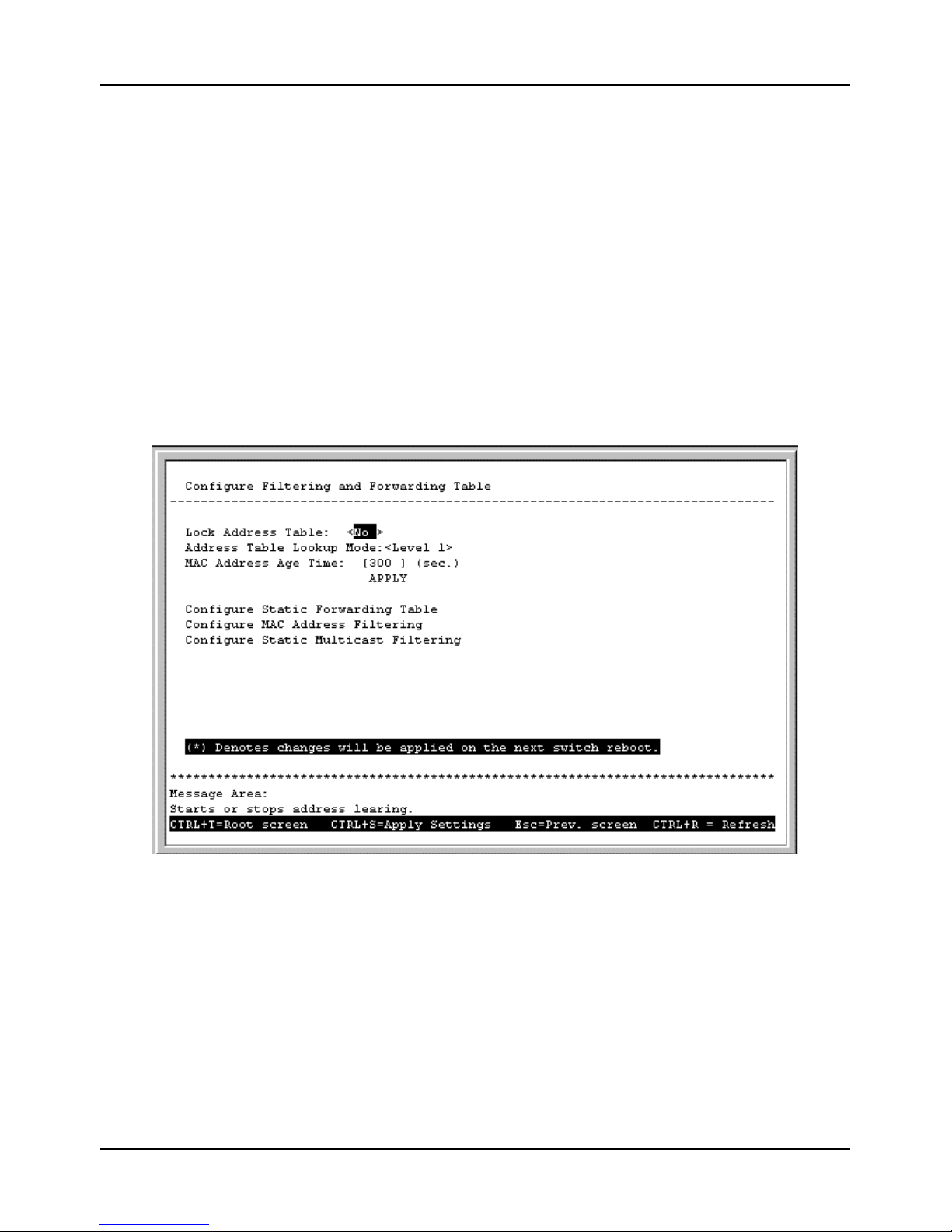
Stackable NWay Ethernet Switch User’s Guide
Using the Console Interface 61
Configure Filtering and Forwarding Table
When a packet hits the Switch, it looks in the filtering and forwarding tables to decide what to do with the packet; either to
filter it off the network, or to forward it through the port on which its destination lies.
Dynamic Filtering and Static Filtering are among the two important features of the Custom Filtering Table. They are
defined here briefly as follows. Dynamic Filtering is defined when a dynamic entry is created by the Learning Process as
a result of observation of network traffic in the Filtering Database. Static Filtering is defined as static entries that may
be added and removed from the Filtering Database by the user. They are not automatically removed by any timeout
mechanism.
The Configure Filtering and Forwarding Table screen allows you to stop or start address learning, change the
way the Switch treats MAC address table entries, and select an age-out time of the MAC address in the selected address
table. This screen also permits you to access three additional configuration screens from the menu at the bottom of the
window.
Choose Configure Filtering and Forwarding Table from the System Configuration menu to access the
following screen:
Figure 6-20. Configure Filtering and Forwarding Table screen
The following fields at the top of the screen can be set:
♦ Lock Address Table Mostly used for security purposes, when the forwarding table is locked the Switch will no
longer learn the MAC addresses for new hosts. If your network configuration doesn’t change, locking the forwarding
table helps keep intruders off your network since any packet coming from an unknown source address will be dropped
by the Switch.
♦ Address Table Lookup Mode This setting allows the user to tailor the MAC address look up procedure. Choices
are Level 0, Level 1, Level 2, Level 3, Level 4, Level 5, Level, 6, Level 7. The higher the level, the more MAC
addresses can be learned by the Switch. However, a side effect is that throughput will be degraded the higher the level
you select. This setting will take effect after your system reboots.
♦ MAC Address Age Time Enter the desired MAC address age-out time in this field (10 to 9999 seconds).
Page 62
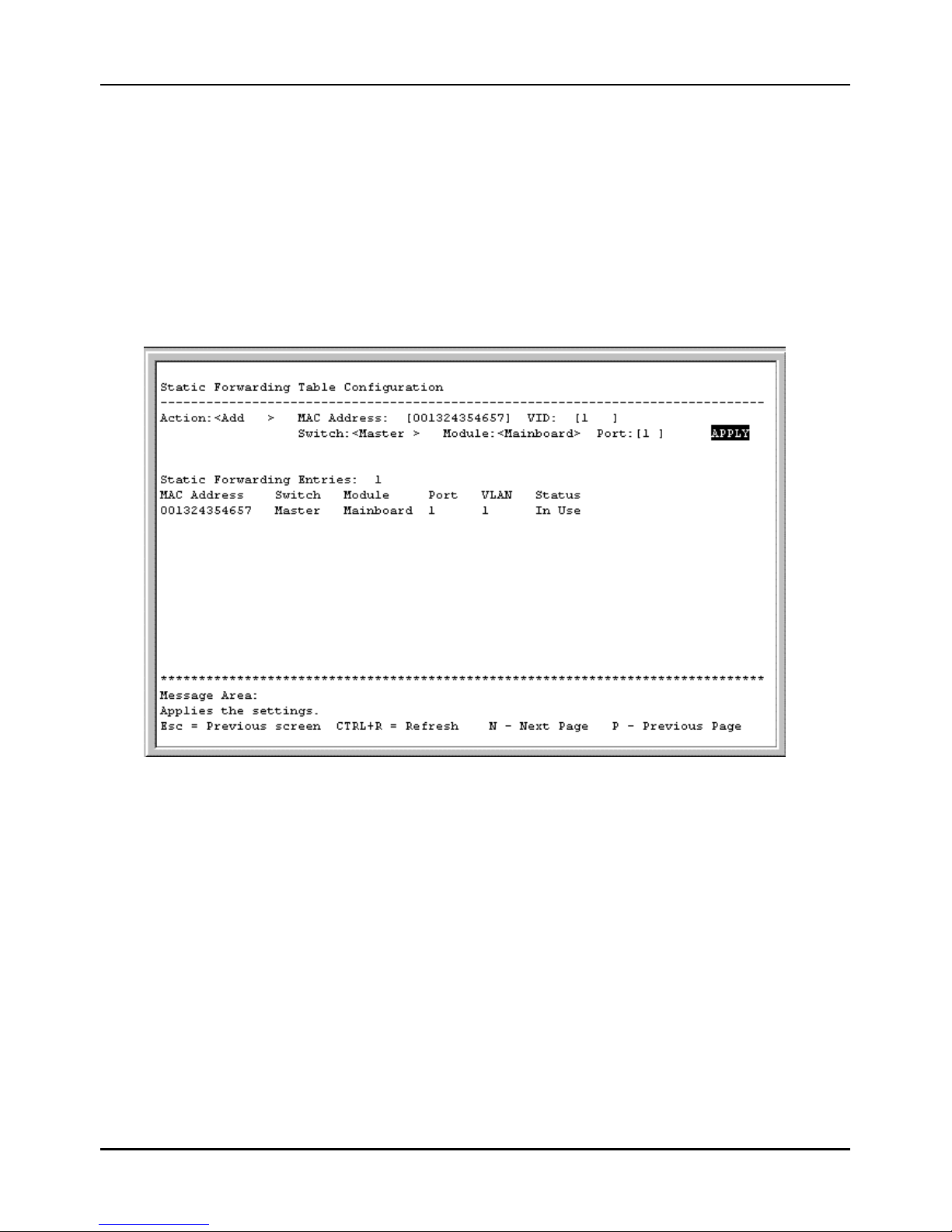
Stackable NWay Ethernet Switch User’s Guide
62 Using the Console Interface
Please refer to the Packet Forwarding section of the “Switch Management Concepts” chapter of this manual for more
detailed information.
Configure Static Forwarding Table
The Static Forwarding Table Configuration screen displays a list of manually defined static unicast MAC
address entries.
To access the Static Forwarding Table Configuration screen, choose Configure Filtering and
Forwarding Table from the System Configuration menu. Then select Configure Static Forwarding
Table from the bottom of the Configure Filtering and Forwarding Table screen. The following screen
appears:
Figure 6-21. Static Forwarding Table Configuration screen
By mapping a MAC address to a destination port, the switch can permanently forward traffic for a specified device through
a specific port, even after long periods of network inactivity or during times of network congestion.
The following fields at the top of the screen can be set:
♦ Action Choose Add or Remove for each entry from the table.
♦ MAC Address Enter a MAC address in this field at the top of the screen. This is the MAC address of the device
that you are creating a permanent forwarding address for. A total of ten destination addresses per page will be seen
at the bottom of the screen. The Switch can hold up to 96 entries.
♦ VID Enter the desired VLAN ID number.
♦ Switch, Module, and Port The Switch, module, and port number are entered in these fields at the top of the
screen. The Switch will always forward traffic to the specified device through this port. The bottom of the screen will
display each corresponding destination address for these three items.
In the lower part of the screen, MAC Address, Switch, Module, Port, VLAN, and Status are all read-only fields. The
status of the static forwarding table entry can be “in use” or “not apply.” “Not apply” means that there is a static filter
Page 63
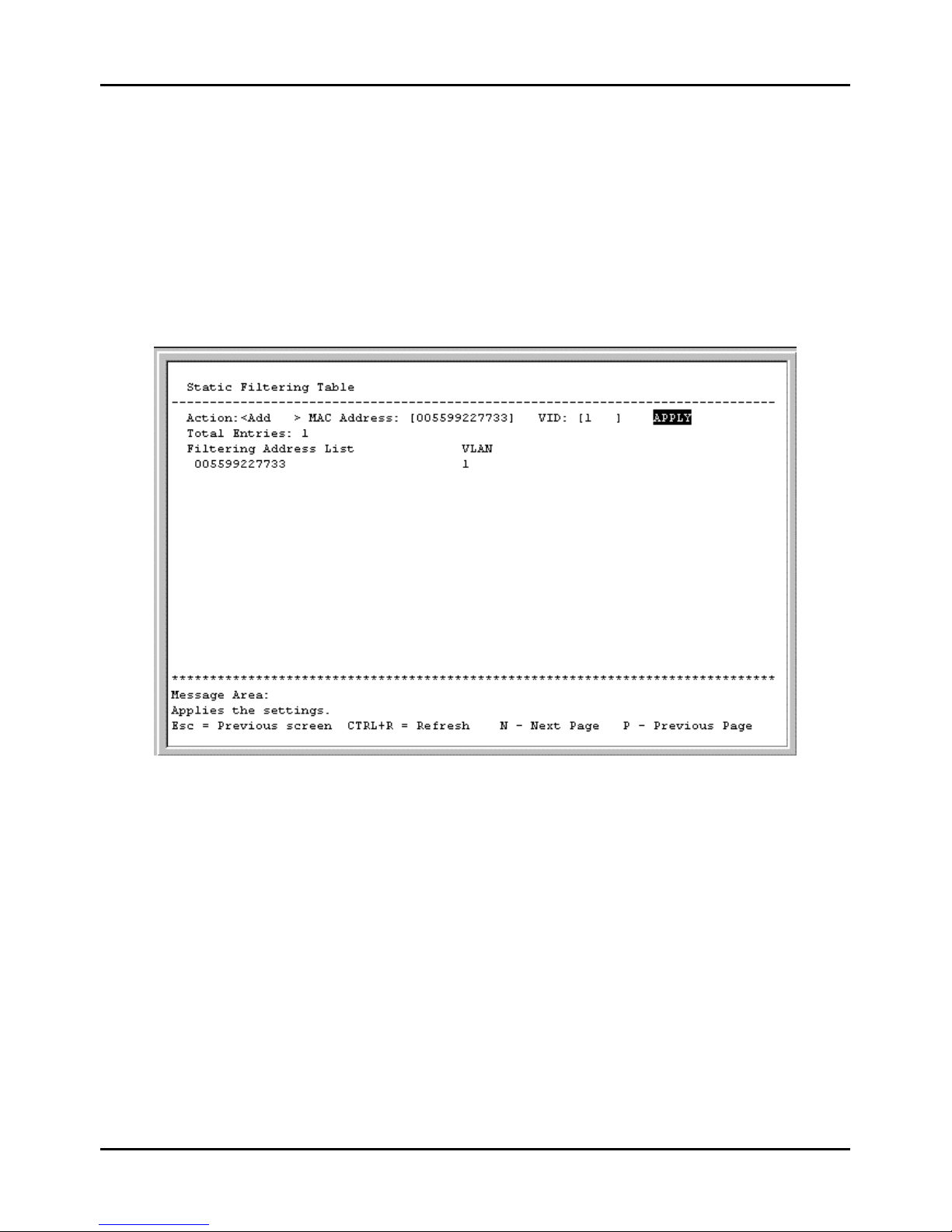
Stackable NWay Ethernet Switch User’s Guide
Using the Console Interface 63
for the same MAC address. Static filters always take precedence over static forwarding entries. The Switch will
automatically upgrade the Status to “in use” once the static filter is removed.
Configure MAC Address Filtering
The Static Filtering Table screen contains filtering information configured into the Switch by (local or network)
management specifying destination addresses which are not allowed to be forwarded. The Switch will check both the
destination and source MAC addresses on all packets.
To access the Static Filtering Table screen, select Configure Filtering and Forwarding Table from the
System Configuration menu. Then select Configure MAC Address Filtering from the bottom of the Configure
Filtering and Forwarding Table screen. The following screen appears:
Figure 6-22. Static Filtering Table screen
To make a change to this screen, choose Add or Remove in the Action field. Then enter the MAC Address and VID. Press
APPLY to let the changes take effect.
Configure Static Multicast Filtering
Multicast filtering allows you to block or forward traffic over each port for one multicast group.
To access the Static Multicast Filtering Table Configuration screen, select Configure Filtering and
Forwarding Table from the System Configuration menu. Then select Configure Static Multicast Filtering
from the bottom of the Configure Filtering and Forwarding Table screen. The following screen appears:
Page 64
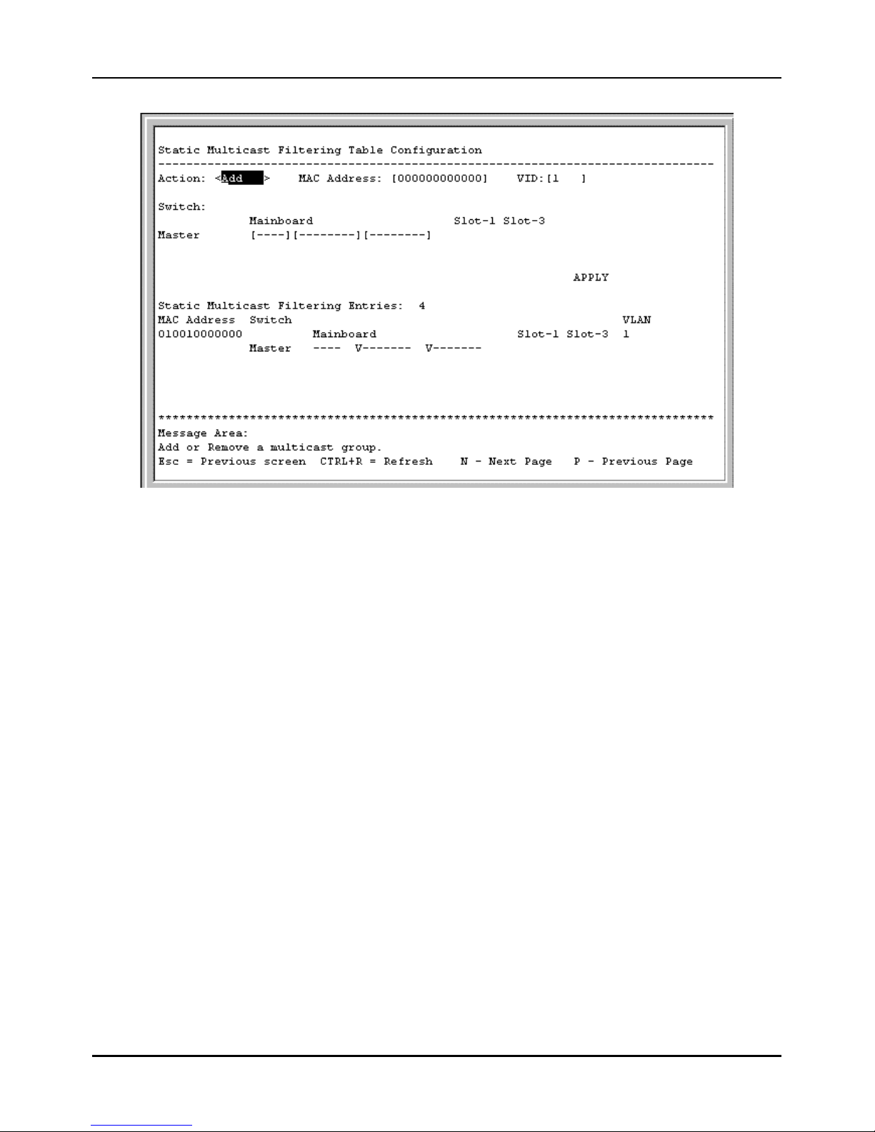
Stackable NWay Ethernet Switch User’s Guide
64 Using the Console Interface
Figure 6-23. Static Multicast Filtering Table Configuration screen
To add an entry or make a change to an entry on the Static Multicast Filtering Table Configuation screen, select
Add or Remove in the first field, enter the multicast MAC address in the next field, enter the VLAN ID number, assign
the outgoing ports by typing a V, and then press APPLY to put the changes into effect.
Configure IGMP
Internet Group Management Protocol (IGMP) allows multicasting on your network. When IP Multicast Filtering is
enabled, the Switch can intelligently forward (rather that broadcast) IGMP queries and reports sent between devices
connected to the Switch and an IGMP-enabled device hosting IGMP on your network.
Basically, in these submenus you define whether the Switch can intelligently forward IGMP packets, and you must also
define which 802.1Q VLANs (if present) can send and receive IGMP and Multicast packets.
To access the IGMP Configuration screen, select Configure IGMP from the System Configuration menu. The
following screen appears:
Page 65
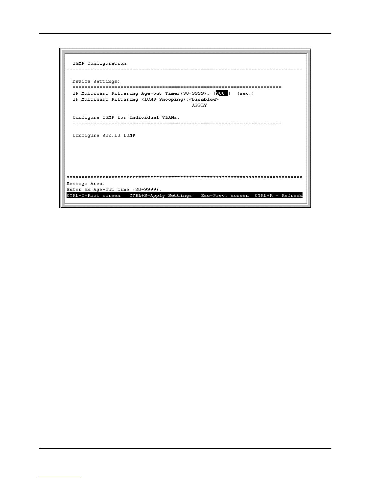
Stackable NWay Ethernet Switch User’s Guide
Using the Console Interface 65
Figure 6-24. IGMP Configuration screen
Items in the above window ar e defined as follows:
♦ IP Multicast Filtering Age-out Timer(30-9999) When this timer expires and the Switch has not observed
(snooped) any IGMP query packets asking whether any stations belong to any Multicast groups, the Switch itself will
send out queries and become the IGMP host on your network.
♦ IP Multicast Filtering (IGMP Snooping) This enables or disables the Switch to intelligently forward IGMP
and Multicast packets instead of broadcasting (flooding) them on all ports. This setting also enables IGMP Snooping,
which enables the Switch to read IGMP packets being forwarded through the Switch in order to obtain forwarding
information from them (learn which ports contain Multicast members).
The bottom of this screen contains a command for VLAN settings that leads to the IEEE 802.1Q IGMP
Configuration menu. Highlight Configure 802.1Q IGMP and press <Enter> to access this screen:
Page 66
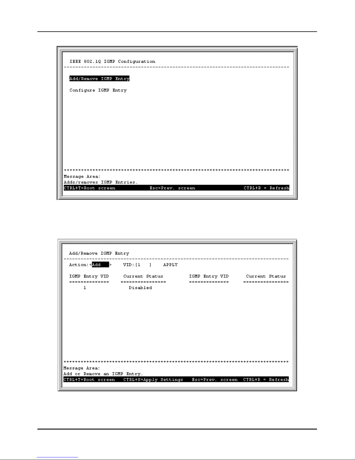
Stackable NWay Ethernet Switch User’s Guide
66 Using the Console Interface
Figure 6-25. IEEE 802.1Q IGMP Configuration screen
Choose Add/Remove IGMP Entry from the screen above to define up to 12 VLANs on the Switch which can send and
receive IGMP packets:
Figure 6-26. Add/Remove IGMP Entry screen
Page 67
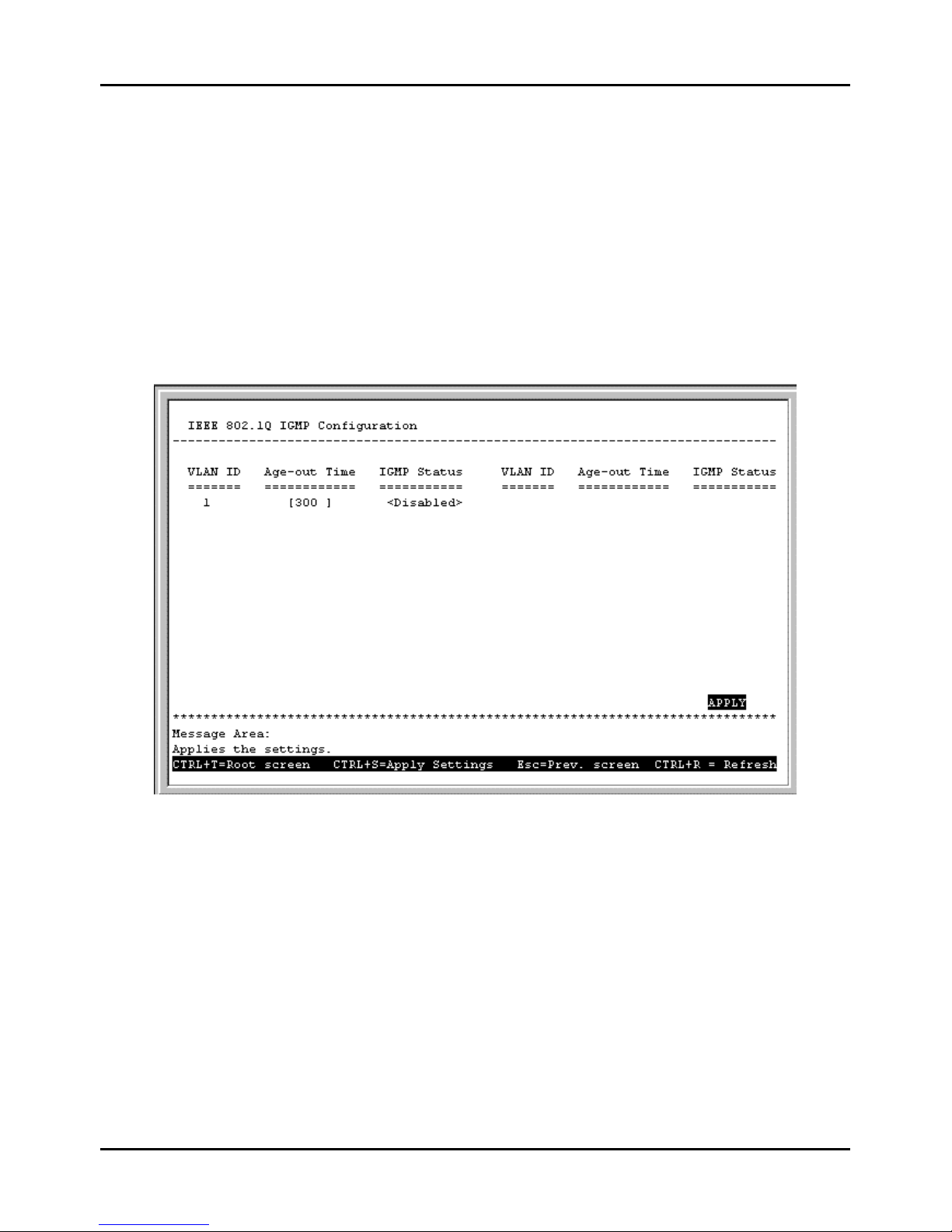
Stackable NWay Ethernet Switch User’s Guide
Using the Console Interface 67
The above screen is used to specify an agent to interface between IGMP and VLAN. The agents are assigned to a VLAN
and allow IGMP query and report packets to be present on the given VLAN. Only 12 agents can exist on the switch at any
one time.
Items in the above screen are described below:
♦ Action Adds/Removes an entry (agent) from the table.
♦ VID The VLAN number that you wish to create an agent for.
Press APPLY to add the agent to the table.
Go back to the IEEE 802.1Q IGMP Configuration menu and choose Configure IGMP Entry in order to
activate/deactivate the agents and configure settings for them. The following IEEE 802.1Q IGMP Configuration
screen appears:
Figure 6-27. IEEE 802.1Q IGMP Configuration screen
This allows you to enable or disable these agents and set aging timers for them.
Items in the above screen are defined as follows:
♦ VLAN ID This is the VID number for the VLAN that has an agent attached to it which enables IGMP packets to be
sent and received.
♦ Age-out Timer If no IGMP query packet has arrived at the Switch before this timer has expired, the Switch will
become the IGMP host for this VLAN.
♦ IGMP Status Activates or deactivates the agent on this VLAN.
Configure VLANs & MAC-based Broadcast Domains
The VLAN Configuration menu displays the status of the current VLAN mode and allows a user to restart the Switch
in IEEE 802.1Q VLANs, Port-based, or MAC-based Broadcast Domains mode, or not to use a selection by choosing
Page 68
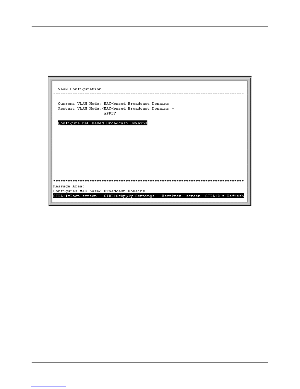
Stackable NWay Ethernet Switch User’s Guide
68 Using the Console Interface
NONE. Please note that the Switch can only support one mode at any given time. Also, each time the mode is changed, the
Switch must be rebooted before the new mode is activated.
If you have selected MAC-based Broadcast Domains an d then rebooted the Switch, Configure MAC-based
Broadcast Domains will appear at the bottom of the VLAN Configuration screen (System Configuration à
Configure VLANs & MAC-based Broadcast Domains):
Figure 6-28. VLAN Configuration screen
The information on the top of the screen is described as follows:
♦ Current VLAN Mode Displays what mode, if any, is currently enabled on the Switch.
♦ Restart VLAN Mode Choose from four settings for this mode: MAC-based Broadcast Domains, IEEE 802.1Q
VLANs, Port-based, or NONE. After being restarted, the Switch will implement the setting you have chosen.
♦ SNMP Vlan If IEEE 802.1Q VLANs is selected, you must also enter a SNMP VLAN ID number in this field. This
is a special VLAN that you designate for SNMP management packets. Make sure the Switch port that the
management station is connected to has this PVID number and is a static member of this VLAN.
Configure MAC-based Broadcast Domains
To create MAC-based broadcast domains, simply create the broadcast domain itself in the Add/Remove MAC-based
Broadcast Domains screen, and then enter MAC addresses to the broadcast domain in the Add/Remove MACbased Broadcast Domain Members screen. Afterwards, restart the Switch and the broadcast domain will be
implemented.
Please note that if the mode is set to MAC-based Broadcast Domains, then the Port Lock function is not supported in
the Port Configuration screen and the Lock Address Table function located on the Configure Filtering and
Forwarding Table screen is not available.
Choose Configure MAC-based Broadcast Domains from the bottom of the VLAN Configuration screen above
to access the MAC-Based Broadcast Domains Configuration menu:
Page 69
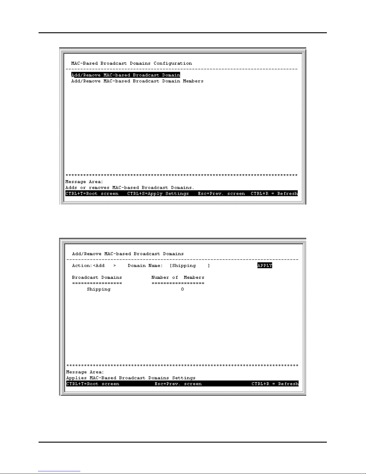
Stackable NWay Ethernet Switch User’s Guide
Using the Console Interface 69
Figure 6-29. MAC-Based Broadcast Domains Configuration menu
Choose Add/Remove MAC-based Broadcast Domains to access the following screen:
Figure 6-30. Add/Remove MAC-based Broadcast Domains screen
The fields you can set are:
Page 70
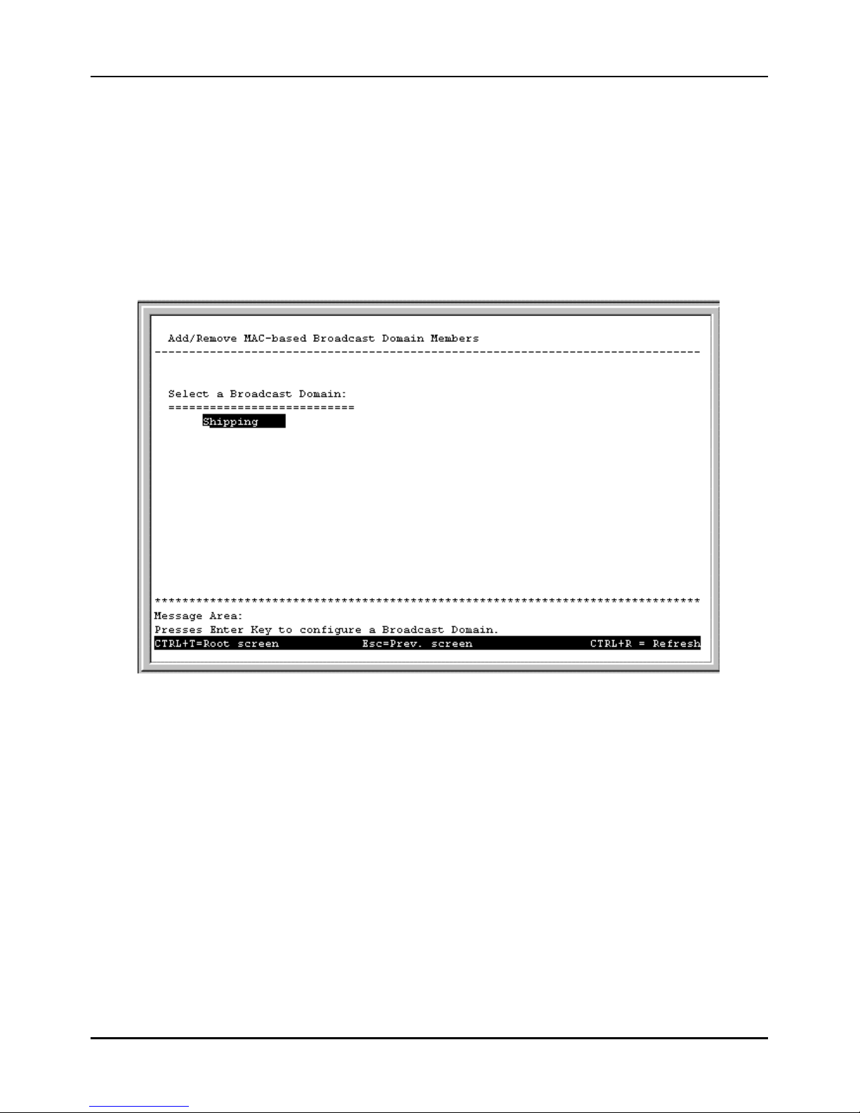
Stackable NWay Ethernet Switch User’s Guide
70 Using the Console Interface
♦ Action Select the desired action by toggling between Add and Remove.
♦ Domain Name Enter the name of the broadcast domain.
Press APPLY to add or remove the designated MAC-based broadcast domain.
Broadcast Domains and Number of Members reflect the current status. They are read-only fields and cannot be changed.
Choose Add/Remove MAC-based Broadcast Domain Members from the MAC-Based Broadcast Domains
Configuration menu to access the following screen:
Figure 6-31. Add/Remove MAC-based Broadcast Domain Members screen
To configure a broadcast domain, highlight the desired entry on the screen above and press <Enter>. The following
Add/Remove MAC-based Broadcast Domain Members screen appears:
Page 71
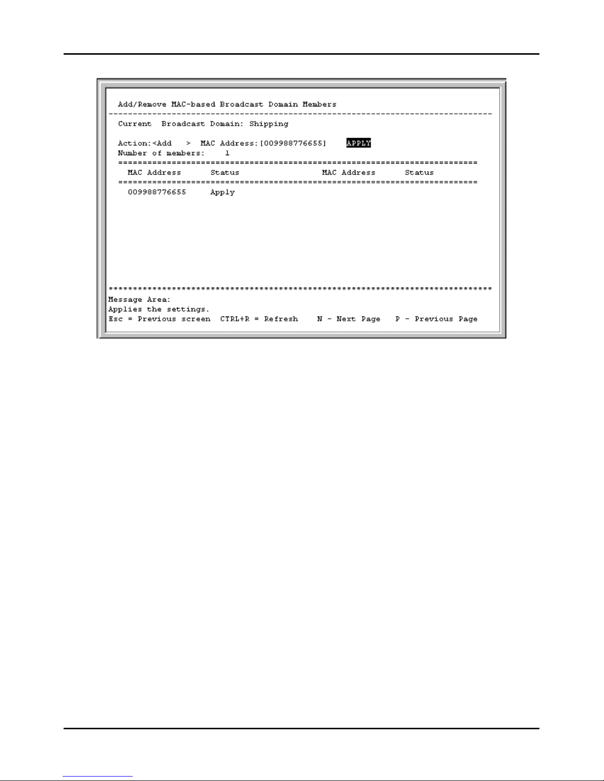
Stackable NWay Ethernet Switch User’s Guide
Using the Console Interface 71
Figure 6-32. Add/Remove MAC-based Broadcast Domain Members screen
The fields you can set are:
♦ Action Select the desired action by toggling between Add and Remove.
♦ MAC Address The MAC address of the broadcast domain member being added or removed.
Please note that the Status field for the MAC address you have entered may read Not-Apply. Once the Switch is restarted
in MAC-based broadcast domain mode, the MAC-addresses will be applied, meaning that the broadcast domain is active.
Current Broadcast Domain, Number of members, MAC Address (in the lower part of the screen), and Status reflect the
current conditions. They are read-only fields and cannot be changed.
Configure Port-based VLANs
Choose Configure Port-based VLANs on the VLAN Configuration screen (System Configuration à
Configure VLANs & MAC-based Broadcast Domains) to access the Port-based VLAN Configuration
menu pictured below (note that if you have just changed to this mode, you must also reboot the Switch before being able to
work with port-based VLANs):
Page 72
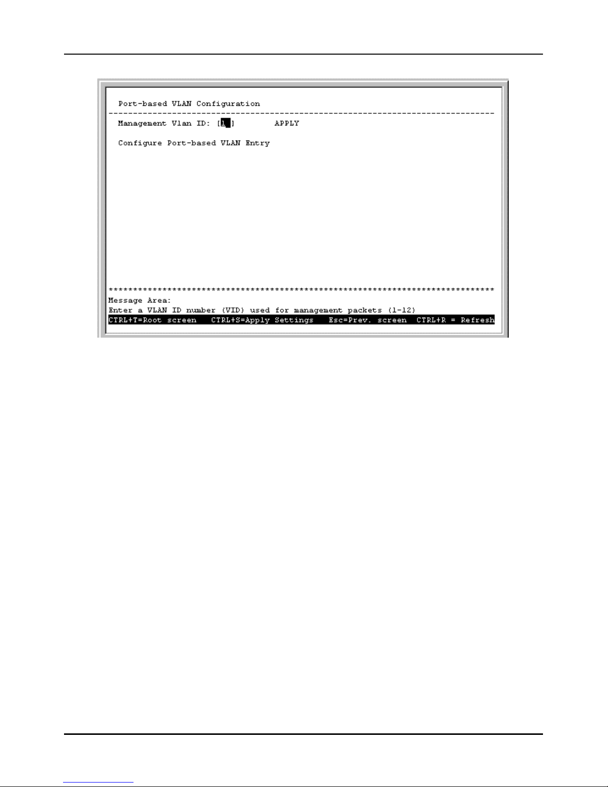
Stackable NWay Ethernet Switch User’s Guide
72 Using the Console Interface
Figure 6-33. Port-based VLAN Configuration menu
The field you can set is:
♦ Management Vlan ID Enter a VLAN ID (VID) from 1 to 12 for use with management packets.
Select Configure Port-based VLAN Entry at the bottom of the menu above to access the following screen:
Page 73
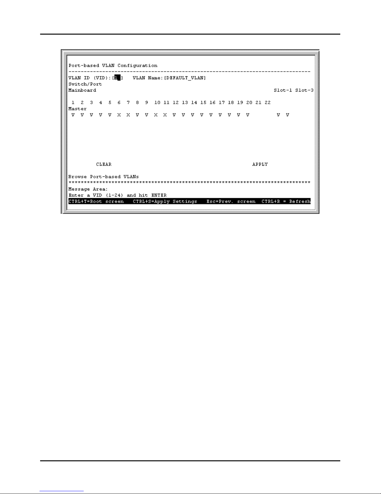
Stackable NWay Ethernet Switch User’s Guide
Using the Console Interface 73
Figure 6-34. Port-based VLAN Configuration screen
The fields you can set are:
♦ VLAN ID (VID) Enter a VLAN ID from 1 to 24 and hit <Enter>. This is the VLAN that will be defined on this
screen. VID 1 is the default VLAN. All ports are designated members of VID 1 when VLANs are enabled. When a port
is assigned to another VLAN, it is removed from VLAN 1. If it is ever removed from the other VLAN, it will
automatically return to being a member of VLAN 1. Thus, all unassigned ports are automatically members of VLAN 1.
♦ VLAN Name Description of the VLAN.
♦ Port Assignments To change port VLAN assignments, you must first enter a VLAN ID number in the VLAN ID
field and press <Enter>. Next, position the cursor over the dash “–“ representing the appropriate port number and press
<space bar> to select V for member. Pressing <space bar> again returns the V back into a ‘–‘. A dash (–) means the port
is not given VLAN membership for the VID entered above. An ‘X’ shows that the port belongs to a different VLAN.
Pressing CLEAR erases all settings for the designated VLAN (VID).
After designating ports as members of the VLAN, press APPLY to let the changes take effect.
Choose Browse Port-based VLANs from the screen above to view the current Port-based VLAN settings.
Page 74
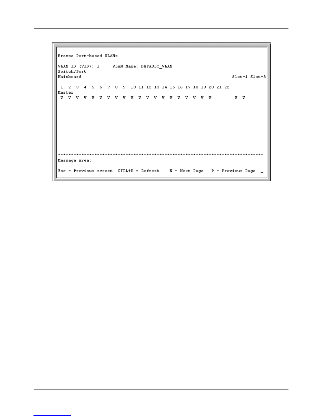
Stackable NWay Ethernet Switch User’s Guide
74 Using the Console Interface
Figure 6-35. Browse Port-based VLANs screen
Configure 802.1Q VLANs
To configure an 802.1Q VLAN, you must do three things:
1. Decide if you want to enable Ingress Filtering and enable it on the chosen ports. Ingress filtering applied on a port
causes the port to examine all incoming packets and check whether the port itself is a member of the VLAN. This is
normally used to keep untagged frames off the Switch, although it can have other uses as well. This setting is
configurable for each port in the Ingress Filtering Check screen.
2. Define which ports will be active members of the VLAN. A port can transmit packets onto only one VLAN. It can
receive packets (be a passive member) on many VLANs . Active VLANs are designations defined by assigning Port
VLAN ID numbers (PVIDs) in the Default port VLAN assignment screen.
3. Define the VLAN itself and which ports will be members (able to receive packets from a port that has this PVID
number). At this point, you need to designate whether a member port will be a Tagging or Untagging member port.
Defining the ports that will be members of a VLAN, and whether they will Tag or Untag packets is done in the 802.1Q
Static VLAN Settings screen.
Choose Configure 802.1Q VLANs on the VLAN Configuration screen (System Configuration à Configure
VLANs & MAC-based Broadcast Domains) to access the 802.1Q VLAN Configuration menu pictured below
(note that if you have just changed to this mode, you must also reboot the Switch before being able to work with IEEE
802.1Q VLANs):
Page 75
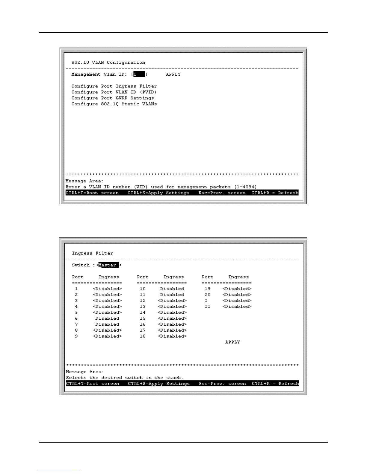
Stackable NWay Ethernet Switch User’s Guide
Using the Console Interface 75
Figure 6-36. 802.1Q VLAN Configuration menu
Choose Configure Port Ingress Filter to access the first item on the menu. The following screen appears:
Figure 6-37. Ingress Filter screen
This screen allows you to set Ingress filtering for each port to either Enabled or Disabled. When a packet arrives at the
port and Ingress filtering is Enabled, the port will check the VLAN ID number of the packet, and its own VIDs. If there is a
Page 76
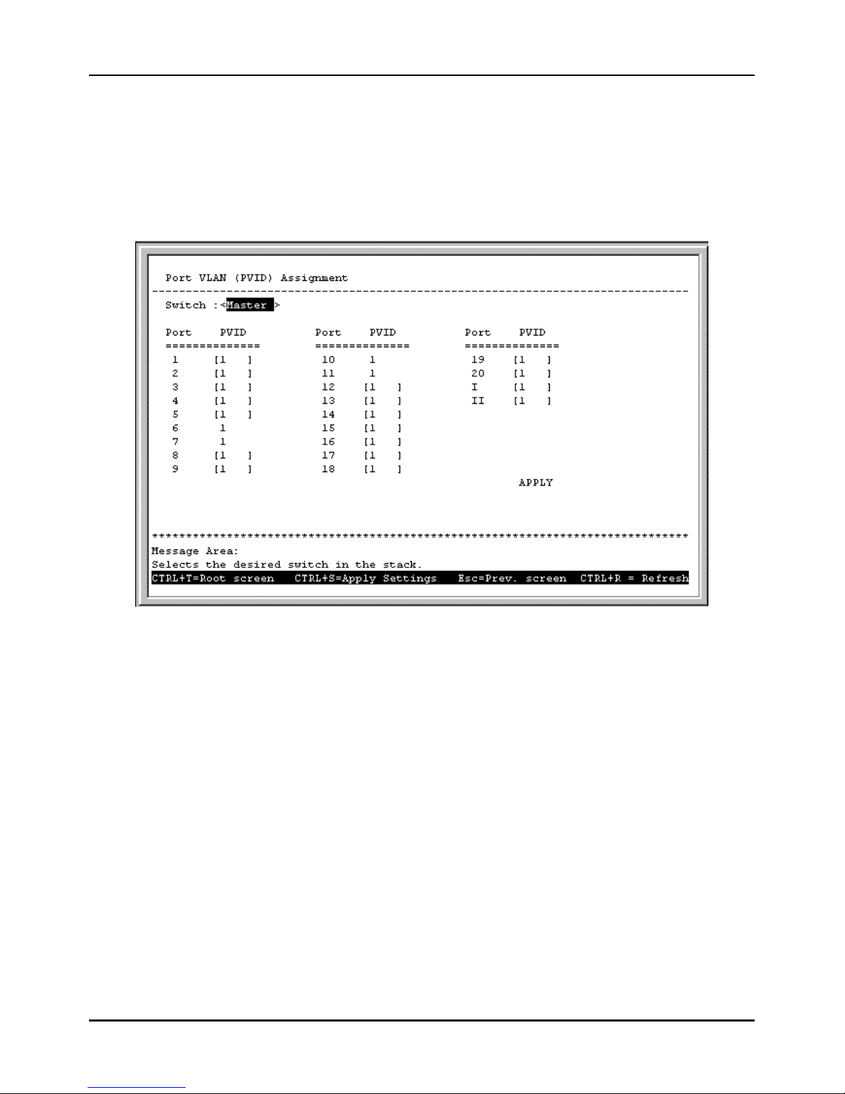
Stackable NWay Ethernet Switch User’s Guide
76 Using the Console Interface
match, the port will receive the packet. If the packet doesn’t have a VLAN tag or the port is not a member of the VLAN for
which the packet is tagged, the packet will be discarded.
Note: If a port is a member of a trunk group but is not the anchor, the items shown in the above table will be read-
only and the values will be the same as those for the anchor port.
Choose Configure Port VLAN ID (PVID) to access the second item on the 802.1Q VLAN Configuration menu.
The following screen appears:
Figure 6-38. Port VLAN (PVID) Assignment screen
This screen allows you to set a Default port VLAN ID number (PVID) for each port. Press APPLY to let the changes take
effect.
Note: If a port is a member of a trunk group but is not the anchor, the items shown in the above table will be read-
only and the values will be the same as those for the anchor port.
Choose Configure Port GVRP Settings to access the third item on the 802.1Q VLANs Configuration menu. The
following screen appears:
Page 77
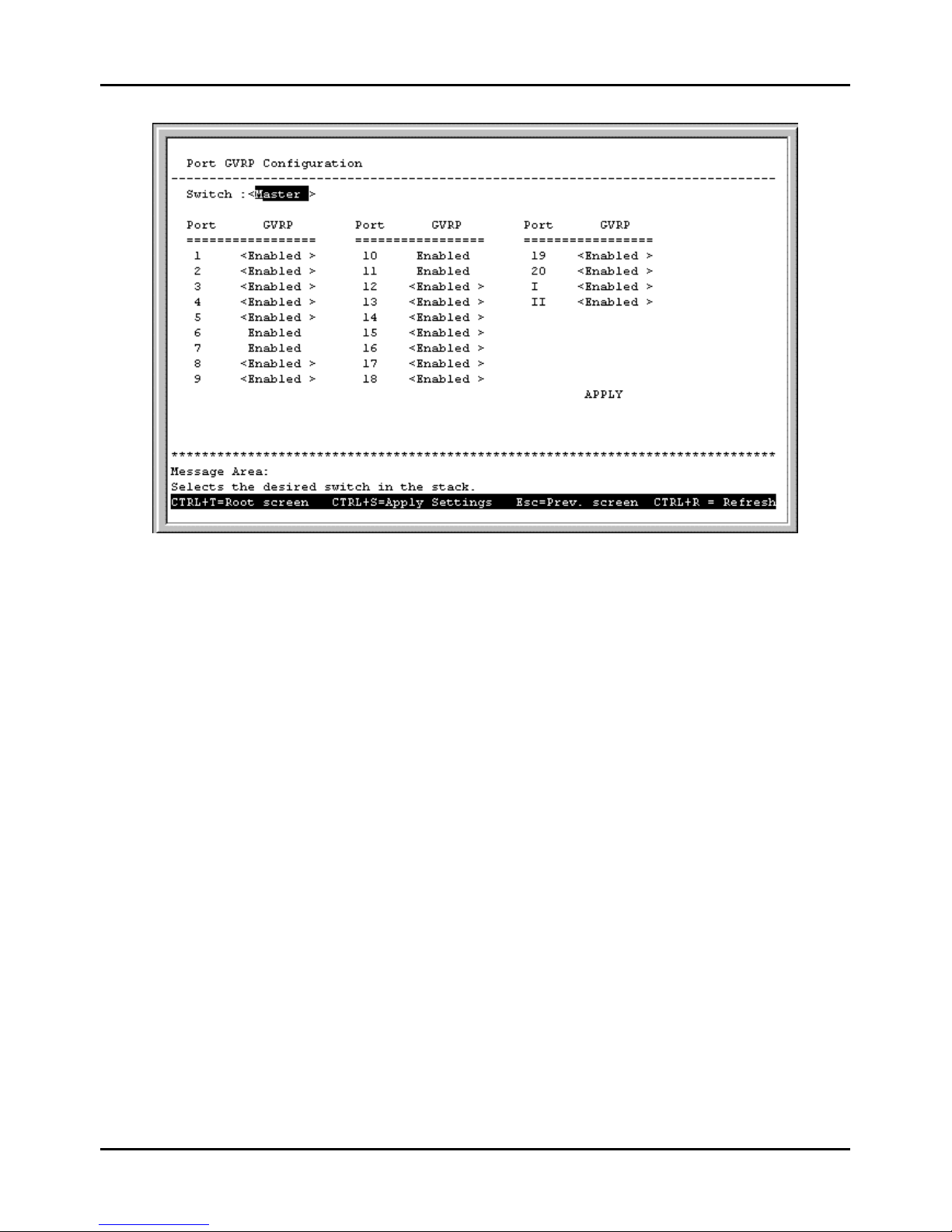
Stackable NWay Ethernet Switch User’s Guide
Using the Console Interface 77
Figure 6-39. Port GVRP Configuration screen
This screen allows you to enable or disable GARP VLAN Registration Protocol (GVRP), where GARP is the Generic
Attribute Registration Protocol, on individual ports. GVRP updates dynamic VLAN registration entries and
communicates the new VLAN information across the network. This allows, among other things, for stations to physically
move to other switch ports and keep their same VLAN settings, without having to reconfigure VLAN settings on the
Switch.
Press APPLY to let your changes take effect.
Choose Configure 802.1Q Static VLANs to access the fourth item on the 802.1Q VLANs Configuration menu.
The following screen appears:
Page 78
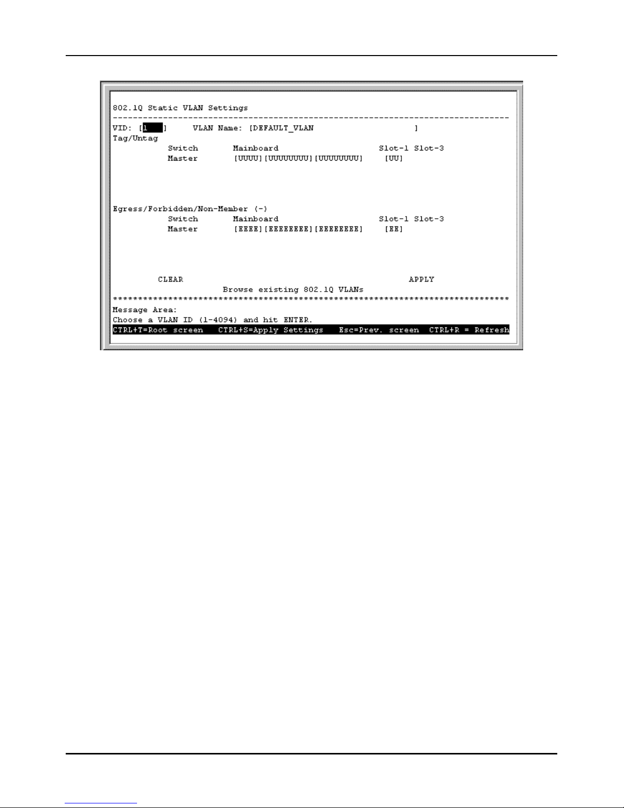
Stackable NWay Ethernet Switch User’s Guide
78 Using the Console Interface
Figure 6-40. 802.1Q Static VLAN Settings screen
The fields you can set are:
♦ VID Enter a VLAN ID from 1 to 4094 and hit <Enter>. This is the VLAN that will be defined on this screen.
♦ VLAN Name Description of the VLAN.
♦ Tag/Untag Toggle between T for tag and U for untag for each port.
♦ Egress/Forbidden/Non-member (–) Position the cursor over the dash “–“ representing the appropriate port
number and press <space bar> to select E for Egress membership, or leave the dash “– “. An E designates the specified
port as a static member of the VLAN. A dash means the port is not given VLAN membership for the VID entered
above.
Choose Browse existing 802.1Q VLANs at the bottom of the 802.1Q Static VLAN Settings screen to access the
following screen:
Page 79
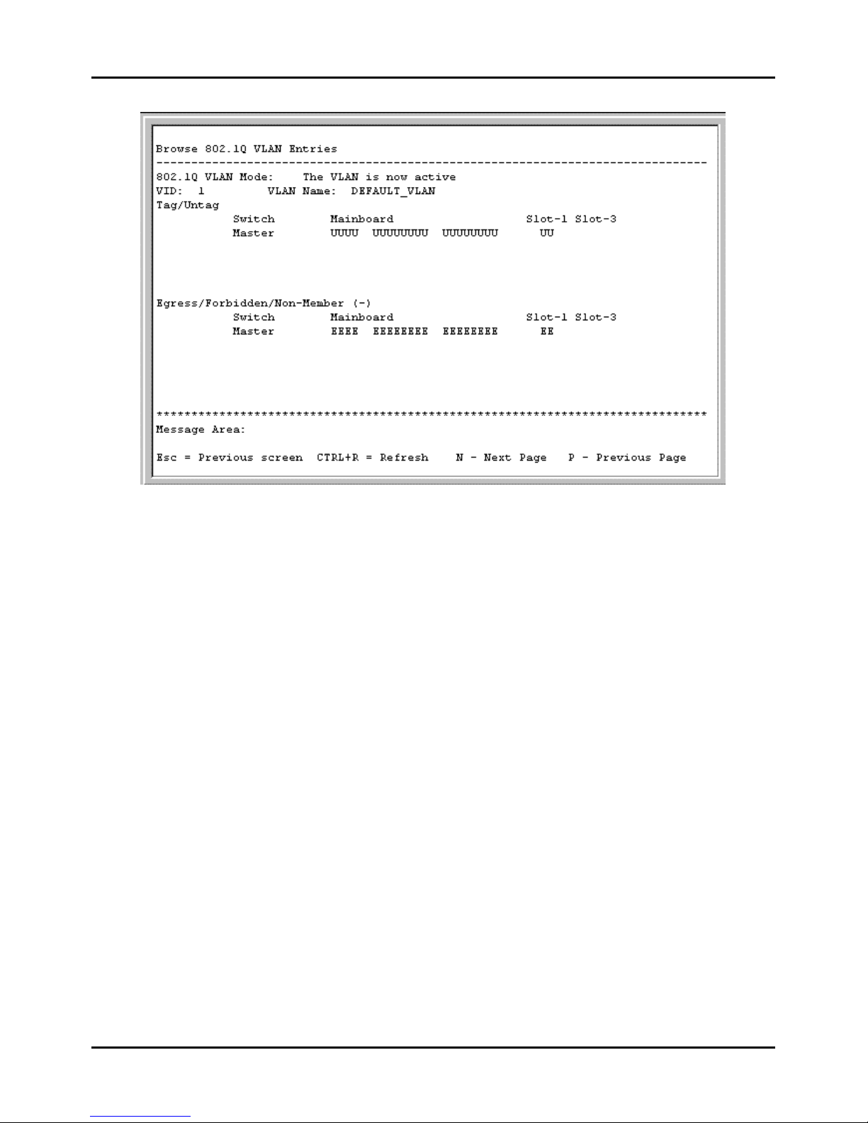
Stackable NWay Ethernet Switch User’s Guide
Using the Console Interface 79
Figure 6-41. Browse 802.1Q VLAN Entries screen
This table displays the current VID and VLAN Name as well as Tag/Untag and Egress/Forbidden/Non-Member status
for all 802.1Q static VLAN entries.
Configure GMRP
Group Multicast Registration Protocol (GMRP) allows multicasts to be sent on a single VLAN without affecting other
VLANs or broadcast domains. Group registration ent ries indicate for each port whether frames to be sent to a group MAC
address and on a certain VLAN should be filtered or discarded. Use the GMRP Configuration screen to enable or
disable GMRP.
Page 80
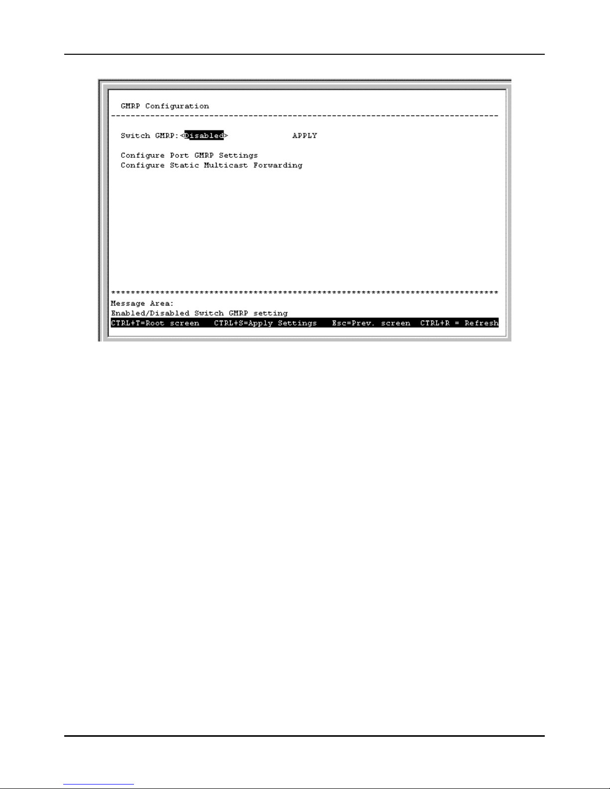
Stackable NWay Ethernet Switch User’s Guide
80 Using the Console Interface
Figure 6-42. GMRP Configuration menu
The Switch GMRP field allows you to either enable or disable GMRP on the Switch by toggling between the two choices
and then pressing APPLY to let the change take effect.
Once GMRP is enabled for the Switch, you then must enable specific ports by selecting Configure Port GMRP
Settings from the GMRP Configuration menu above. The GMRP Configuration screen appears:
Page 81
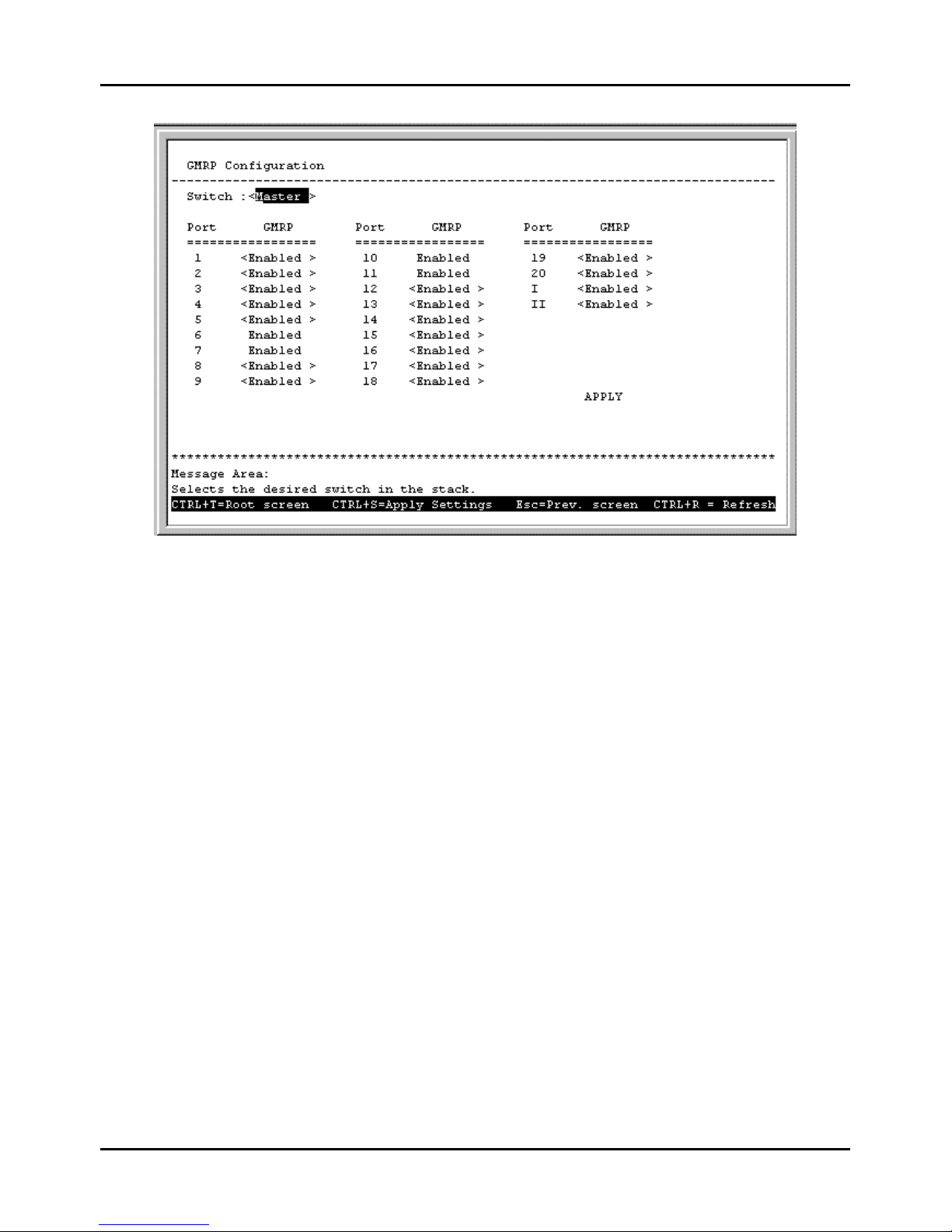
Stackable NWay Ethernet Switch User’s Guide
Using the Console Interface 81
Figure 6-43. GMRP Configuration screen
Use this screen to enable or disable GMRP on individual ports. Press APPLY to let your changes take effect.
Choose Configure Static Multicast Forwarding from the GMRP Configuration menu to access the Static
Multicast Forwarding Table Configuration screen that appears below:
Page 82
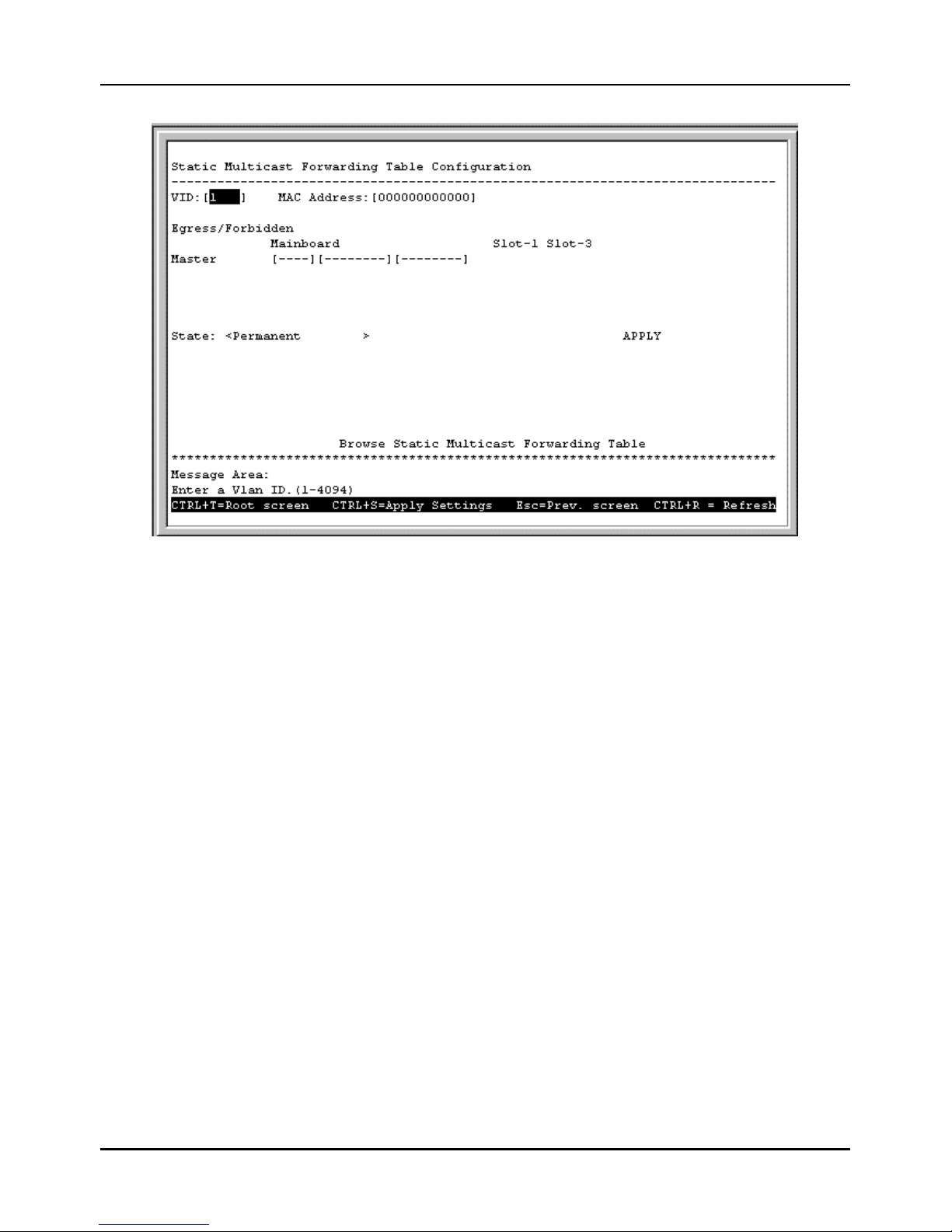
Stackable NWay Ethernet Switch User’s Guide
82 Using the Console Interface
Figure 6-44. Static Multicast Forwarding Table Configuration screen
To add an entry or make a change to an entry on the Static Multicast Forwarding Table, enter a VLAN ID number,
enter a MAC address, choose Egress or Forbidden for each port, choose a State (Delete on Reset, Delete on Timeout,
Invalid, or Permanent), and then press APPLY to put the change into effect.
Items in the above screen are defined as follows:
♦ VID This is the VLAN that will be defined on this screen. Note a VLAN ID number is from 1 to 4094.
♦ MAC Address The MAC address of the newly created Static Multicast Forwarding Table entry.
♦ Egress/Forbidden Position the cursor over the dash “–“ representing the appropriate port number and press the
<space bar> to select E for Egress, F for Forbidden, or leave the dash “–“. An E designates the specified port as a static
member of the VLAN. A dash means the port is not given VLAN membership for the VID entered above. An F forbids
the port from joining a VLAN dynamically.
♦ State Choose how you want the Switch to deal with the newly created Static Multicast Forwarding table entry:
Delete on Reset, Delete on Timeout, Invalid, or Permanent.
Choose Browse Static Multicast Forwarding Table from the bottom of the Static Multicast Forwarding
Table Configuration screen above to access the following:
Page 83
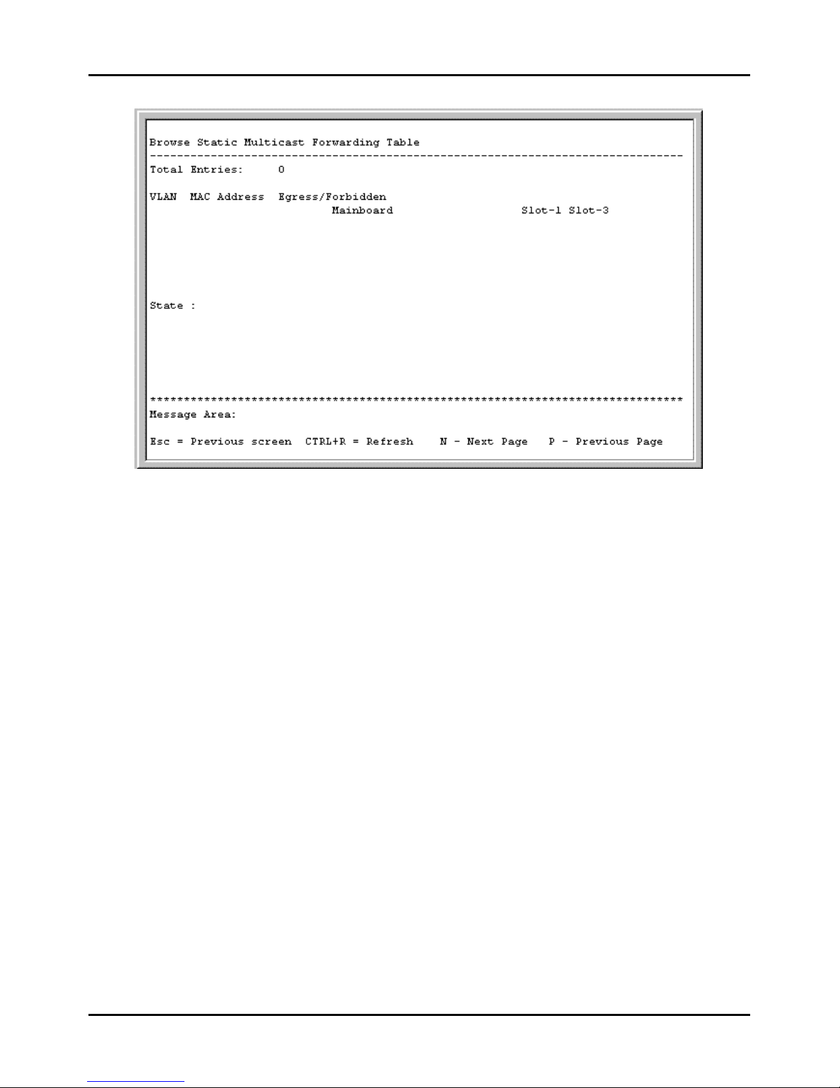
Stackable NWay Ethernet Switch User’s Guide
Using the Console Interface 83
Figure 6-45. Browse Static Multicast Forwarding Table screen
This screen contains information pertaining to the Static Multicast Forwarding Table.
Update Firmware and Configuration Files
The Switch is capable of obtaining its configuration settings (the same settings defined in this console program), as well as
updated versions of its internal switching software (the console program itself), using TFTP (Trivial File Transfer
Protocol). You can use the Update Firmware and Configuration Files screen to control this feature.
Choose Update Firmware and Configuration Files to access the fourth item on the Switch’s main menu. The
following screen appears:
Page 84
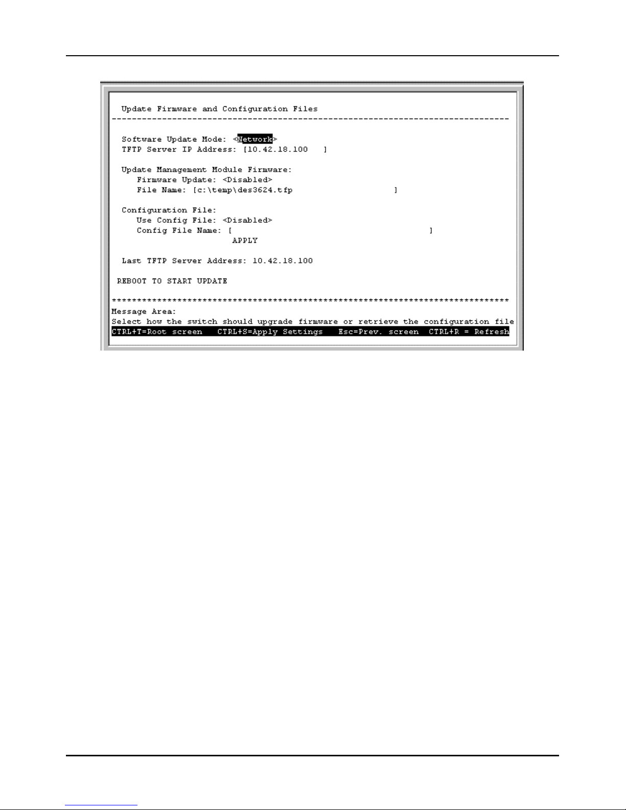
Stackable NWay Ethernet Switch User’s Guide
84 Using the Console Interface
Figure 6-46. Update Firmware and Configuration Files screen
After making your changes in the fields above, press REBOOT TO START UPDATE to initiate the update sequence.
The fields you can set are:
♦ Software Update Mode Set to either network or SLIP. Determines whether the configuration file should be
obtained through the Ethernet network or through the console port.
♦ TFTP Server IP Address The IP address of the TFTP server where the runtime (switching software) or
configuration file is located. This entry is used only if the Firmware Update is set to Enabled.
♦ Firmware Update Determines whether or not the Switch will try to look for a runtime image file on the TFTP
server.
♦ File Name The complete path and filename of the runtime image file on your TFTP server to be uploaded to the
Switch.
♦ Use Config File Toggle to Enabled to use the settings in a configuration text file when the switch is reset
(rebooted). The configuration file is explained in detail in the Sample Configuration File Appendix .
♦ Config File Name The complete path and filename on the TFTP server for the configuration file to use.
Last TFTP Server Address is a read-only field that displays the IP address of the last TFTP server to be accessed.
Special Note Concerning Firmware Updates
1. Never download new firmware through a trunked port. Doing so may result in a failed download, broadcast storm,
or other network problems.
2. Avoid changing active links and do not make new loops on the network when downloading new firmware.
3. Downloading new firmware may result in the loss of some or all Switch settings. We therefore strongly
recommend performing a factory reset and then restarting the Switch after a successful firmware download.
Page 85
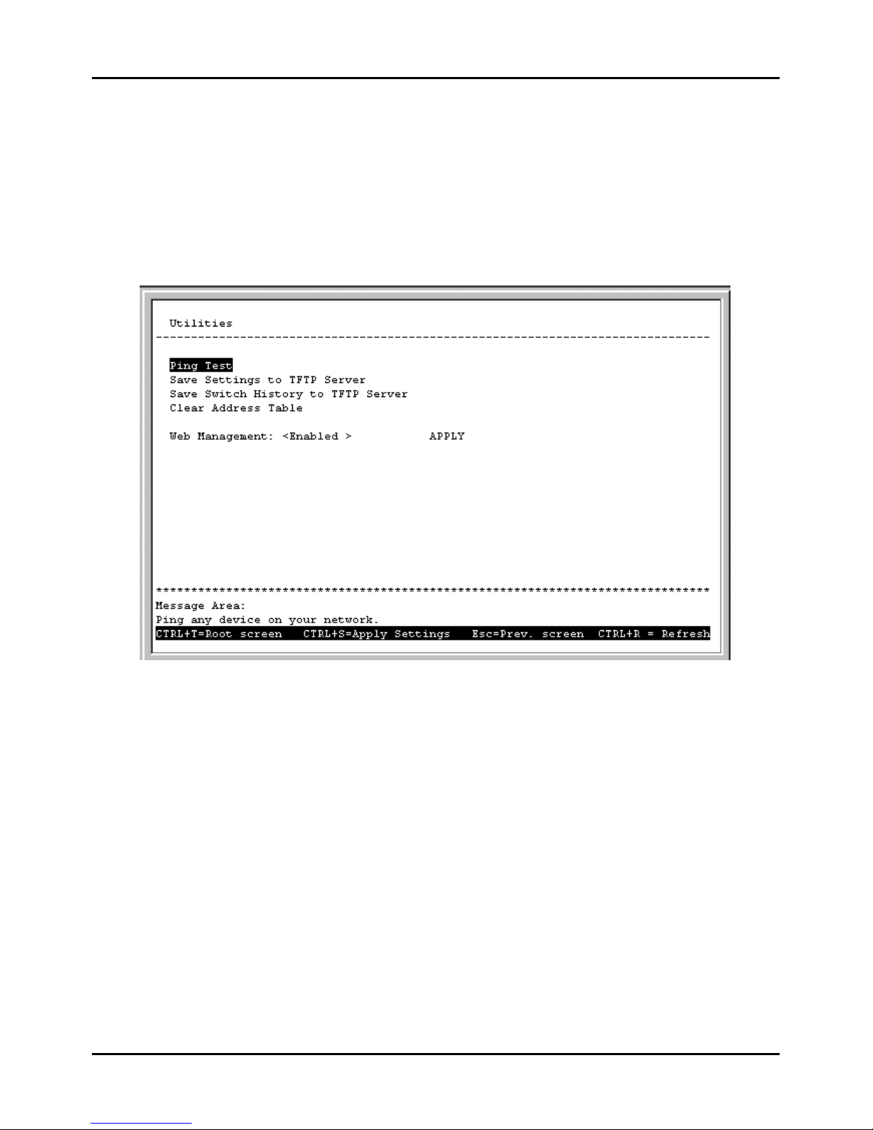
Stackable NWay Ethernet Switch User’s Guide
Using the Console Interface 85
4. Firmware updates are handled by the PROM code, which doesn’t recognize VLAN tags. You should therefore
make sure the Switch port to which the TFTP server is connected is not a tagging port.
System Utilities
The Utilities menu offers four system utility options, Ping Test, Save Settings to TFTP Server, Save Switch
History to TFTP Server , and Clear Address Table.
Choose System Utilities on the main menu to access the Utilities menu seen below:
Figure 6-47. Utilities menu
Ping Test
Choose Ping Test to access the following screen:
Page 86
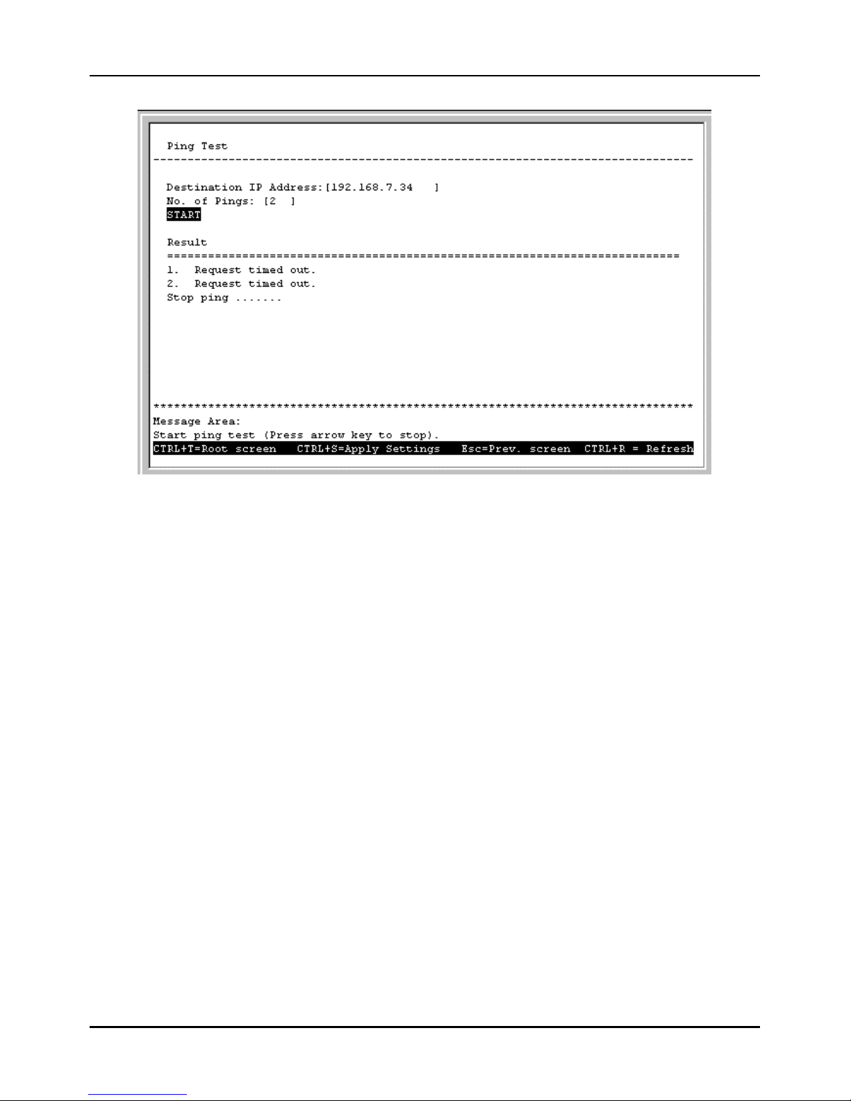
Stackable NWay Ethernet Switch User’s Guide
86 Using the Console Interface
Figure 6-48. Ping Test screen
After filling in the fields above, press START to initiate the Ping test.
The fields you can set are:
♦ Destination IP Address The IP address of the device to be Pinged.
♦ No. of Pings Amount of times the Switch should send the Ping (1-255). If zero is chosen, the Switch will continue
Pinging indefinitely.
In the lower part of the Ping Test screen, you can view the Result of the ping test.
Save Settings to TFTP Server
Choose Save Settings to TFTP Server from the Utilities menu (under System Utilities on the main menu) to
access the following screen:
Page 87
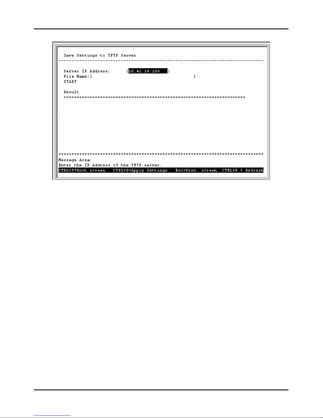
Stackable NWay Ethernet Switch User’s Guide
Using the Console Interface 87
Figure 6-49. Save Settings to TFTP Server screen
Press START to begin the upload. The result will be displayed in the lower part of the screen.
The fields you can set are:
♦ Server IP Address The IP address of the TFTP server where you wish to save the settings for the Switch.
♦ File Name The complete path and filename for the file.
Save Switch History to TFTP Server
Choose Save Switch History to TFTP Server from the Utilities menu (under System Utilities on the main
menu) to access the following screen:
Page 88
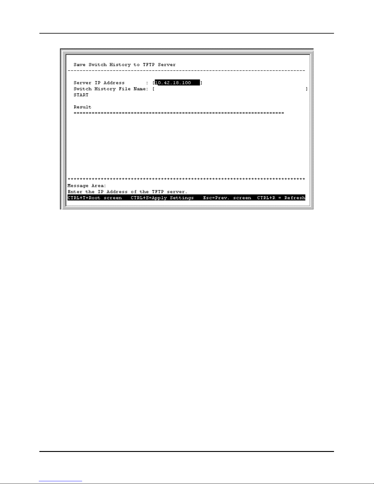
Stackable NWay Ethernet Switch User’s Guide
88 Using the Console Interface
Figure 6-50. Save Switch History to TFTP Server screen
Press START to begin the file save. The result will be displayed in the lower part of the screen.
The fields you can set are:
♦ Server IP Address The IP address of the TFTP server where the switch history file will be located.
♦ File Name The complete path and filename on the TFTP server for the file.
Clear Address Table
Choose Clear Address Table from the Utilities menu (under System Utilities on the main menu) to clear the
entire Address Table (also known as the Filtering and Forwarding table).
Community Strings and Trap Stations
The Switch sends out SNMP traps to network management stations whenever certain exceptional events occur, such as
when the Switch is turned on or when a system reset occurs. The Switch allows traps to be routed to up to four different
network management hosts.
For a detailed list of trap types used for this Switch, see the Traps section in the “Switch Management Concepts”
chapter.
SNMP (version 1) implements a rudimentary form of security by requiring that each request include a community name.
A community name is an arbitrary string of characters used as a “password” to control access to the Switch. If the Switch
receives a request with a community name it does not recognize, it will trigger an authentication trap.
The SNMP allows up to four different community names to be defined. The community name public is defined by
default; you can change this name in addition to adding others. You will need to coordinate these names with the
community name settings you use in your network management system.
Page 89
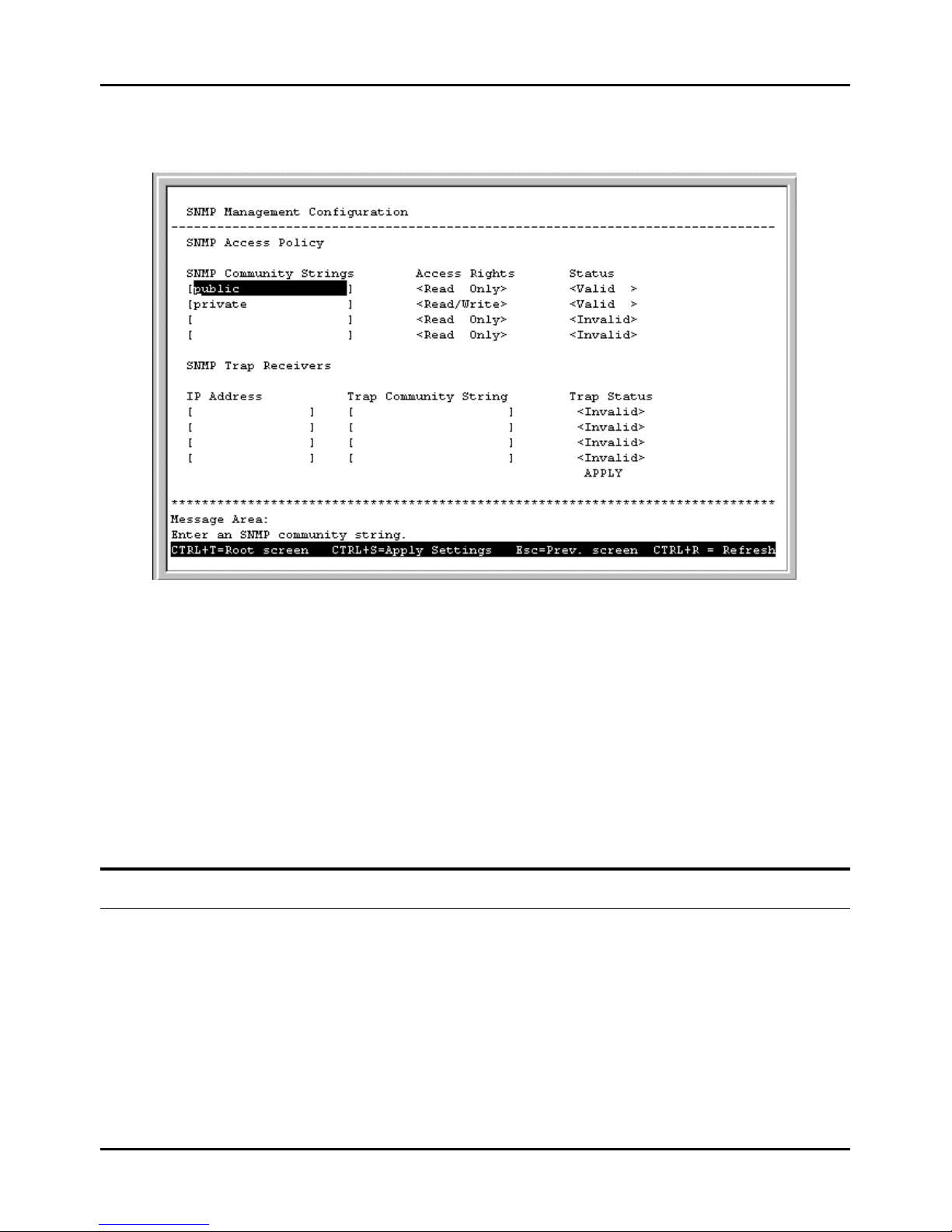
Stackable NWay Ethernet Switch User’s Guide
Using the Console Interface 89
Choose Community Strings and Trap Stations to access the third item on the main menu. The following screen
appears:
Figure 6-51. SNMP Manager Configuration screen
The following SNMP Manager and Trap Manager Configuration parameters can be set:
♦ SNMP Community String/Trap Community String The community string that will be included on
SNMP packets sent to and from the Switch. Any station not privy to this community will not receive the packet.
♦ Access Right Allows each community to be separately set to either Read Only, meaning that the community
member can only view switch settings or Read/Write, which allows the member to change settings in the switch.
♦ Status/Trap Status Determines whether this community name entry is Valid or Invalid. An entry can be
disabled by changing its status to Invalid.
♦ IP Address The IP address of the network management station to receive traps.
Switch Monitoring
The Switch uses an SNMP agent which monitors different aspects of network traffic. The SNMP agent keeps counters and
statistics on the operation of the Switch itself, and on each port on the Switch. The statistics obtained can be used to
monitor the conditions and general efficiency of the Switch.
Network Monitoring
The Network Monitoring menu offers six items, Traffic Statistics , Browse Address Table, Switch History,
Browse IGMP Status, Browse GVRP Status, and Browse GMRP Status.
Choose Network Monitoring from the main menu. The following menu appears:
Page 90
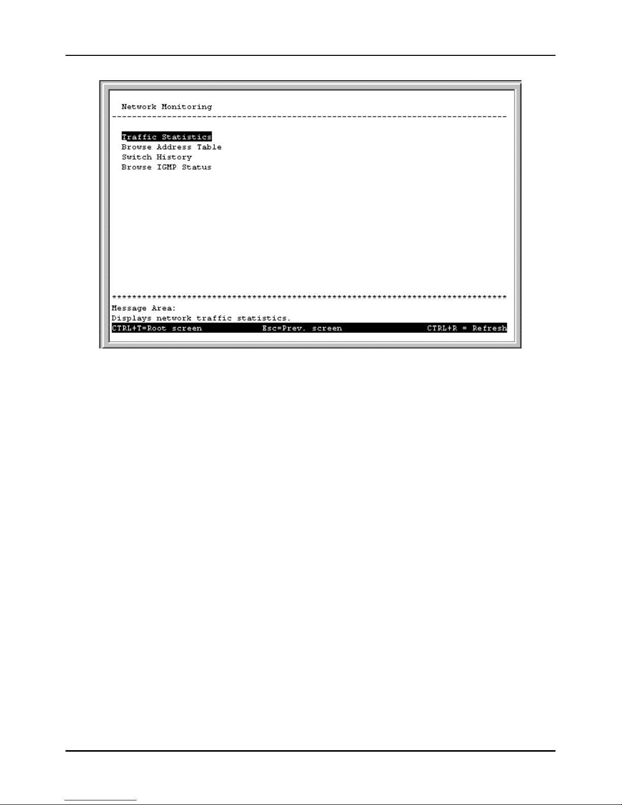
Stackable NWay Ethernet Switch User’s Guide
90 Using the Console Interface
Figure 6-52. Network Monitoring menu
The first item on this menu permits you to access four different tables that observe the condition of each individual port.
Traffic Statistics
To display the Traffic Statistics menu, choose the first item on the Network Monitoring menu. The following menu
appears:
Page 91
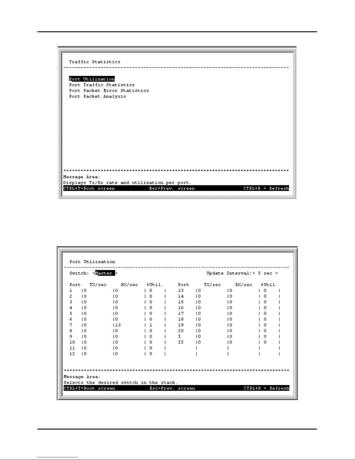
Stackable NWay Ethernet Switch User’s Guide
Using the Console Interface 91
Figure 6-53. Traffic Statistics menu
Port Utilization
To access the first item on the Traffic Statistics menu, choose Port Utilization. The following table appears:
Figure 6-54. Port Utilization screen
Page 92
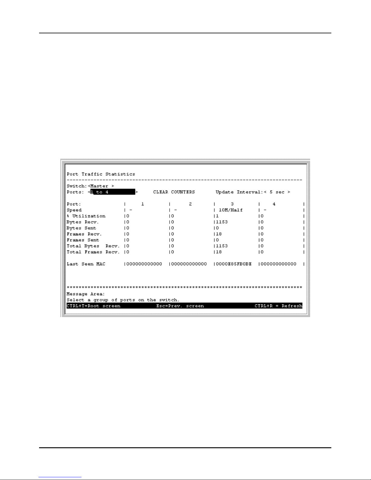
Stackable NWay Ethernet Switch User’s Guide
92 Using the Console Interface
Select the desired device in the Switch field and the desired increment setting in the Update Interval field: 5 sec, 15 sec,
30 sec, 1 min, or Suspend.
The statistic counters displayed are defined as follows:
♦ TX/sec The number of good bytes sent from the respective port per second.
♦ RX/sec The number of good bytes received per second. This also includes local and dropped packets.
♦ %Util. This shows the percentage of available bandwidth each port is using over the amount of time specified by the
update interval. For example, when a 10 Mbps port is relaying packets at 5 Mbps, the utilization is 50%.
Port Traffic Statistics
To access the second item on the Traffic Statistics menu, choose Port Traffic Statistics. The following table
appears:
Figure 6-55. Port Traffic Statistics screen
Select the desired device in the Switch field, the desired setting in the Ports field, and the desired increment setting in the
Update Interval field: 5 sec, 15 sec, 30 sec, 1 min, or Suspend. Press CLEAR COUNTERS to clear all counters for a
desired port group.
The statistic counters displayed are defined as follows:
♦ Speed If the link is up, the speed and duplex status will be displayed; if the link is down “–” will be displayed.
♦ % Utilization This shows the percentage of available bandwidth each port is using over the amount of time
specified by the update interval. For example, when a 10 Mbps port is relaying packets at 5 Mbps, the utilization is
50%.
♦ Bytes Recv. The number of good bytes received. This also includes local and dropped packets.
♦ Bytes Sent The number of good bytes sent from the respective port.
Page 93
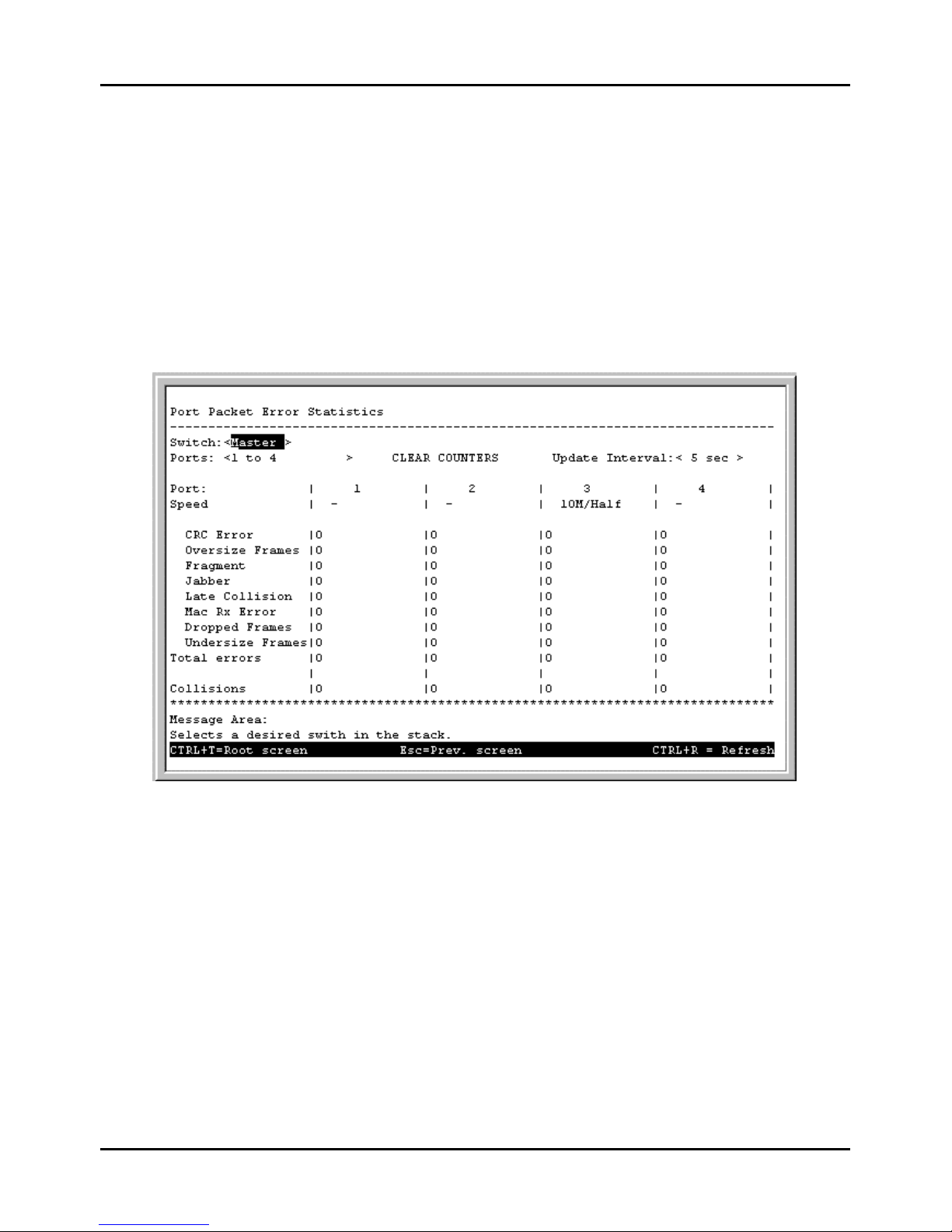
Stackable NWay Ethernet Switch User’s Guide
Using the Console Interface 93
♦ Frames Recv. The number of good frames received. This also includes local and dropped packets.
♦ Frames Sent The number of good frames sent from the respective port.
♦ Total Bytes Recv. The number of bytes received, good and bad.
♦ Total Frames Recv. The number of frames received, good and bad.
♦ Last Seen MAC The MAC address of the last device that sent packets over this port.
Port Packet Error Statistics
To access the third item on the Traffic Statistics menu, choose Port Packet Error Statistics. The following table
appears:
Figure 6-56. Port Packet Error Statistics table
Select the desired device in the Switch field, the desired setting in the Ports field, and the desired increment setting in the
Update Interval field: 5 sec, 15 sec, 30 sec, 1 min, or Suspend. Press CLEAR COUNTERS to clear all counters for a
desired port group.
The statistic counters displayed are defined as follows:
♦ Speed If the link is up, the speed and duplex status will be displayed; if the link is down “–” will be displayed.
♦ CRC Error The number of frames that fail the CRC integrity check.
♦ Oversize Frames The number of good frames with length greater than 1536 bytes and therefore are greater than
the maximum legal length.
♦ Bad Fragment The number of packets less than 64 bytes with either bad framing or an invalid CRC. These are
normally the result of collisions.
Page 94
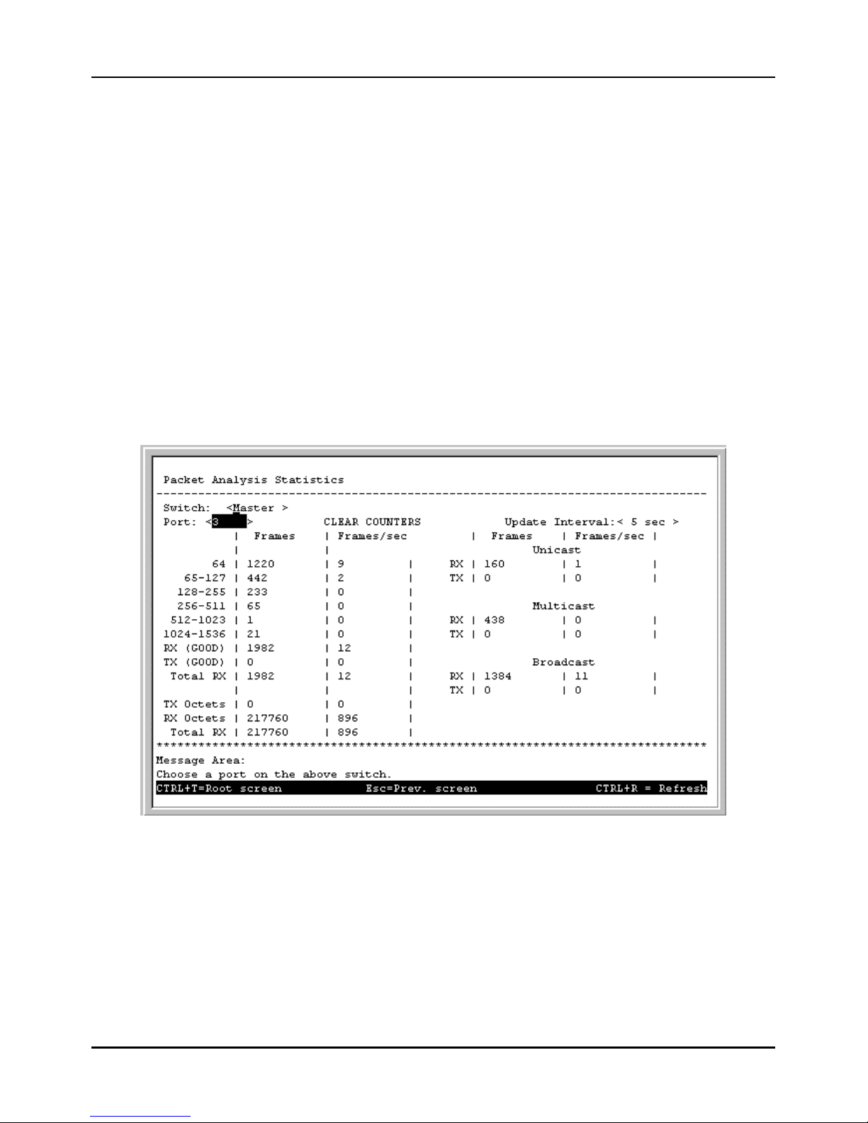
Stackable NWay Ethernet Switch User’s Guide
94 Using the Console Interface
♦ Jabber The number of frames with length more than 1536 bytes and with CRC error or misalignment (bad
framing).
♦ Late Collision The number of collisions that occur at or after the 64th byte (octet) in the frame.
♦ Mac Rx Error The number of frames with received MAC Errors.
♦ Dropped Frames The number of frames which are dropped by this port since the last Switch reboot.
♦ Undersize Frames The number of frames detected that are less than the minimum permitted frame size of 64
bytes and have a good CRC. Undersize frames usually indicate collision fragments, a normal network occurrence.
♦ Total errors The sum of the CRC Error, Oversize Frames, Bad Fragment, Jabber, Late Collision, Mac Rx Error,
Dropped Frames, and Undersize Frames counters.
♦ Collisions The number of times packets have collided on this port.
Port Packet Analysis Statistics
To access the fourth item on the Traffic Statistics menu, choose Port Packet Analysis Statistics. The following
table appears:
Figure 6-57. Packet Analysis Statistics table
Select the desired device in the Switch field, the desired port in the Port field, and the desired increment setting in the
Update Interval field: 5 sec, 15 sec, 30 sec, 1 min, or Suspend. Press CLEAR COUNTERS to clear all counters for a
desired port.
The statistic counters displayed are defined as follows:
♦ 64, 65-127, 128-255, 256-511, 512-1023, 1024-1536 The number of good frames of various length ranges, both valid
and invalid.
♦ RX (GOOD) The number of good frames received. This also includes local and dropped packets.
Page 95
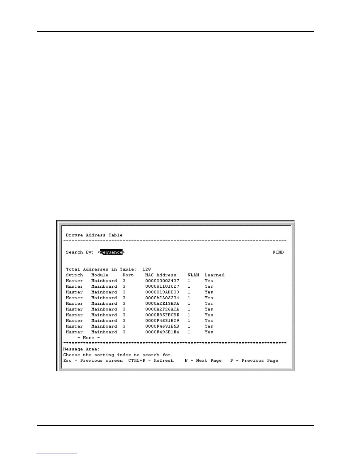
Stackable NWay Ethernet Switch User’s Guide
Using the Console Interface 95
♦ TX (GOOD) The number of good frames sent from the respective port.
♦ Total RX The number of frames received, good and bad.
♦ TX Octets The number of good bytes sent from the respective port.
♦ RX Octets The number of good bytes received. This also includes local and dropped packets.
♦ Total RX The number of bytes received, good and bad.
♦ Unicast RX/Unicast TX The number of good unicast frames received and sent. This includes dropped unicast
packets.
♦ Multicast RX/Multicast TX The number of good multicast frames received and sent. This includes local and
dropped multicast packets.
♦ Broadcast RX/Broadcast TX The number of good broadcast frames received and sent. This includes dropped
broadcast packets.
Browse Address Table
The Browse Address Table screen allows the user to view which Switch port(s) a specific network device uses to
communicate on the network. You can sort this table by MAC address, port, VLAN ID, and sequence. This is useful for
viewing which ports one device is using, or which devices are using one port.
To display the Browse Address Table screen, choose Network Monitoring from the main menu and then choose
Browse Address Table. The following screen appears:
Figure 6-58. Browse Address Table
To browse by MAC address, select MAC in the Search By field, fill in the MAC address field, and then press FIND.
To browse by port number, select Port in the Search By field, choose the desired Switch and Module in the respective
fields, enter the number of the Port you want to configure, and then press FIND.
Page 96
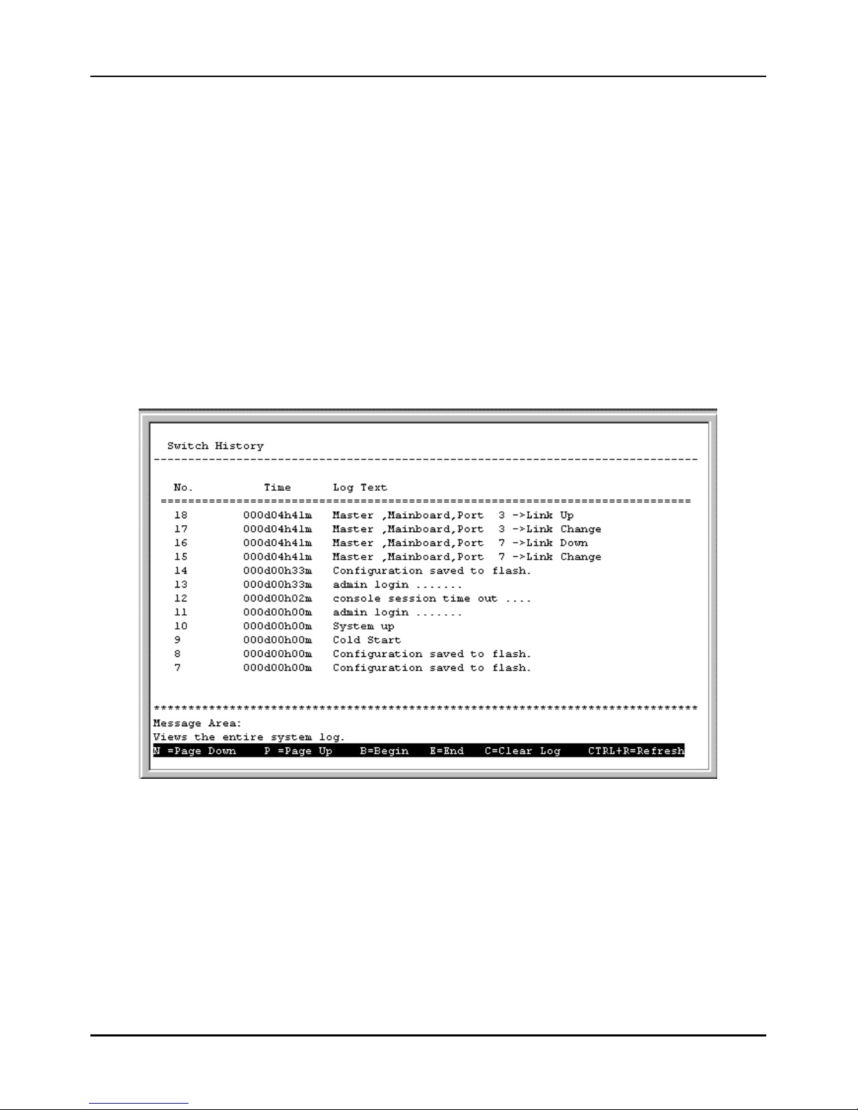
Stackable NWay Ethernet Switch User’s Guide
96 Using the Console Interface
To browse by VLAN ID, select VID in the Search By field, enter the desired VLAN in the field offered, and then press
FIND.
To browse by sequence, select Sequence in the Search By field, and then press FIND.
The lower part of the screen is a read-only Browse Address Table that contains the Total Addresses in Table, as well as
the Switch, Module, Port, MAC Address, VLAN, and Learned status of each entry. Use N to advance to the next page and
P to return to the previous page.
Switch History
The Network Monitoring menu allows the user to view the Switch history. This wo rks like a trap and event receiver
except it only captures trap/events generated by the Switch itself. For example, the switch history includes when the
system is rebooted, when a console session is timed out, when a new link is established, and when configuration is saved to
flash memory.
To display the Switch History screen, choose Network Monitoring from the main menu and then choose Switch
History. The following screen appears:
Figure 6-59. Switch History screen
The switch history entries are listed chronologically from the last time the Switch was rebooted. Use the following keys to
move around the screen above: N – Page down, P – Page up, B – Begin, E – End, and C – Clear Log. CTRL+R will refresh
the screen.
Browse IGMP Status
The Browse IGMP Status function allows you to browse Internet Group Management Protocol (IGMP). The Switch is able
to recognize IGMP queries and reports sent between stations and an IGMP router. When enabled for IGMP snooping, the
Switch can open or close a port to specific devices based on the IGMP messages sent from the device to the router or vice
versa.
Page 97
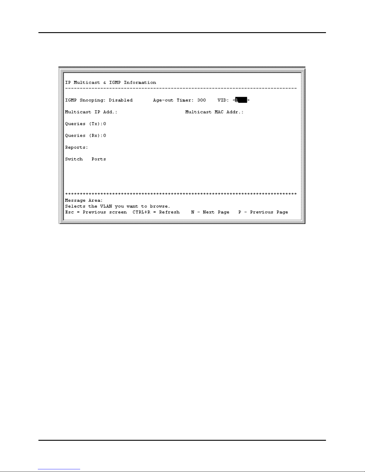
Stackable NWay Ethernet Switch User’s Guide
Using the Console Interface 97
To display the IP Multicast & IGMP Information screen, choose Network Monitoring from the main menu and
then choose Browse IGMP Status. The following screen appears:
Figure 6-60. IP Multicast & IGMP Information screen
This screen displays the number of IGMP queries and reports for each active IP multicast group detected by the Switch.
You can also view which Switch ports support each multicast group and enter a VLAN ID number in the field on the right.
The fields displayed are defined as follows:
♦ IGMP Snooping Indicates whether IGMP snooping is Enabled or Disabled.
♦ Age-out Timer Displays the time the Switch waits between IGMP queries.
♦ VID Enter the desired VLAN ID number.
♦ Multicast IP Add. The Multicast IP address of the Multicast group being displayed.
♦ Multicast MAC Addr. The Multicast MAC address of the multicast group being displayed.
♦ Queries (Tx) The number of IGMP requests sent by the switch.
♦ Queries (Rx) The number of IGMP requests that have arrived at a switch port.
♦ Reports The number of notifications sent from each station to the IGMP host, signifying that the station is still
(or wants to be) part of a multicast group.
♦ Switch Ports The Switch ports supporting the selected multicast group.
Browse GVRP Status
The GVRP Status screen allows you to browse GARP (Generic Attribute Registration Protocol) VLAN Registration
Protocol (GVRP).
Page 98
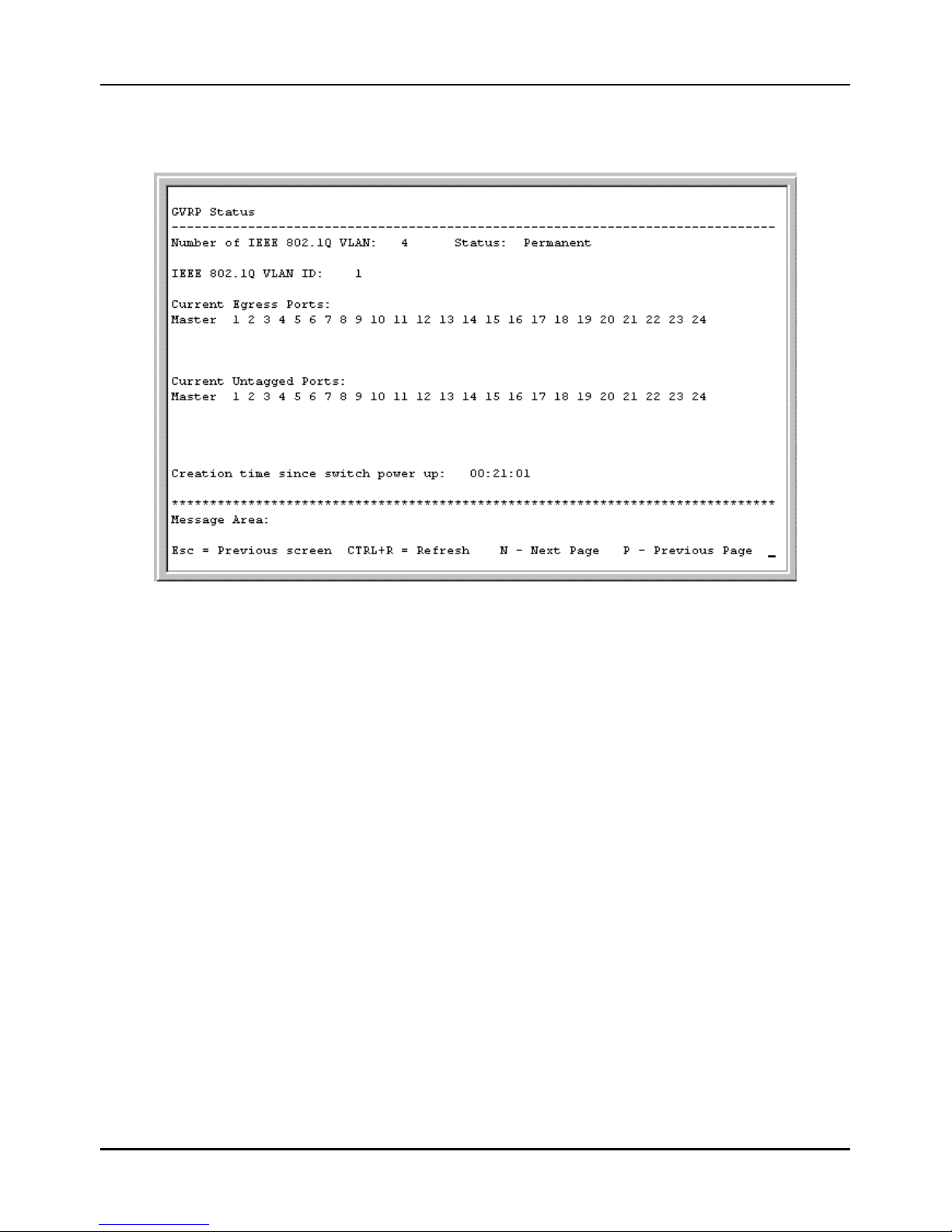
Stackable NWay Ethernet Switch User’s Guide
98 Using the Console Interface
To display the GVRP Status screen, choose Network Monitoring from the main menu and then choose Browse
GVRP Status. The following screen appears:
Figure 6-61. GVRP Status screen
This screen contains information pertaining to GVRP. Press N to view the status of additional IEEE 802.1Q VLANs.
Browse GMRP Status
The Browse GMRP Status screen allows you to browse Group Multicast Registration Protocol (GMRP).
To display the GMRP Status screen, choose Network Monitoring from the main menu and then choose Browse
GMRP Status. The following screen appears:
Page 99
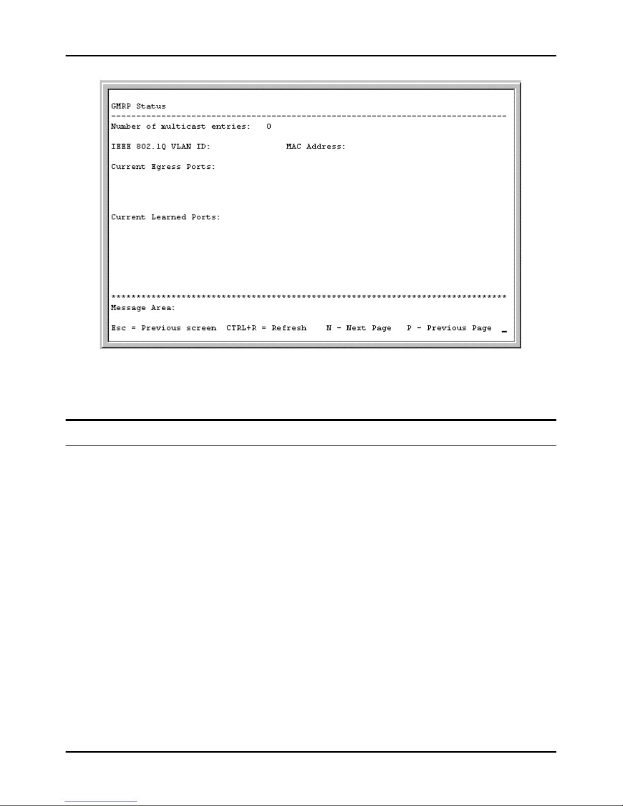
Stackable NWay Ethernet Switch User’s Guide
Using the Console Interface 99
Figure 6-62. GMRP Status screen
This screen contains information pertaining to the GMRP status of IEEE 802.1Q VLANs.
Resetting the Switch
You can use the console interface to reset the Switch, either performing a Restart System or a Factory Reset (which
sets all of the Switch’s parameters to what they were when the Switch was delivered from the factory).
Restart System
To perform a system reset, choose Restart System from the main menu.
Page 100
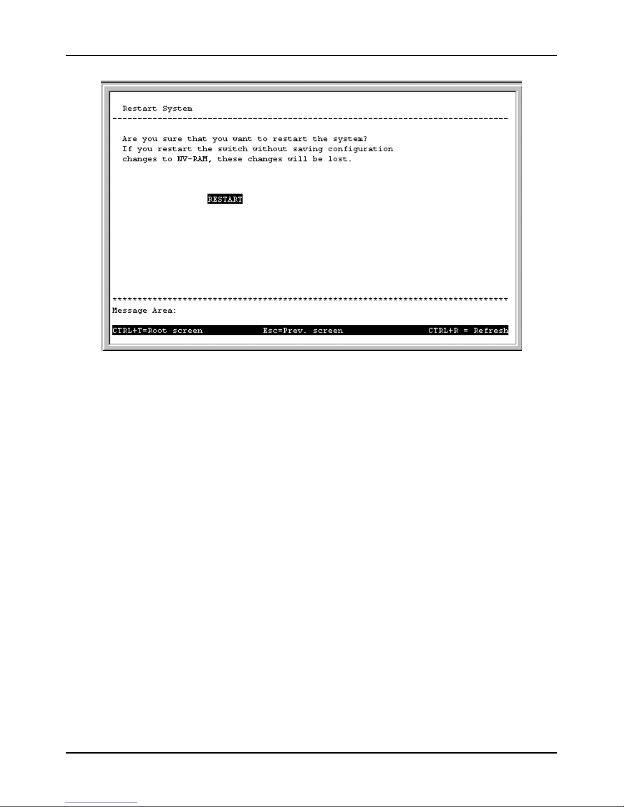
Stackable NWay Ethernet Switch User’s Guide
100 Using the Console Interface
Figure 6-63. Restart System screen
The computer will be rebooted once you press RESTART.
Factory Reset
Before performing a Factory Reset , be absolutely certain that this is what you want to do. Once the reset is done, all of
the Switch’s settings stored in NV -RAM (including TCP/IP parameters, SNMP parameters, the enabled/disabled settings
of ports, security settings, etc.) w ill be erased and restored to values present when the Switch was purchased.
Note: After performing the Factory Reset , make sure to redefine the IP settings for the Switch in the Configure IP
Address menu. Then perform a Restart System on the Switch. After these three procedures are performed,
your Factory Reset is complete.
Choose Factory Reset from the main menu. The following screen appears:
 Loading...