

Page 1
3
Page 2

D-Link Switch User Manual
FCC Warning
This equipment has been tested and found to comply with the regulations for a Class A digital device,
pursuant to Part 15 of the FCC Rules. These limits are designed to provide reasonable protection against
harmful interference when the equipment is operated in a commercial environment. This equipment
generates, uses, and can radiate radio frequency energy and, if not installed and used in accordance with
this user’s guide, may cause harmful interference to radio communications. Operation of this equipment in a
residential area is likely to cause harmful interference, in which case the user will be required to correct the
interference at his/her own expense.
CE Mark Warning
This is a Class A product. In a domestic environment, this product may cause radio interference, in which
case the user may be required to take adequate measures.
VCCI Warning
UL Warning
a) Elevated Operating Ambient Temperature- If installed in a closed or multi-unit rack assembly, the
operating ambient temperature of the rack environment may be greater than room ambient. Therefore,
consideration should be given to installing the equipment in an environment compatible with the
manufacturer's maximum rated ambient temperature (Tmra).
b) Reduced Air Flow- Installation of the equipment in a rack should be such that the amount of air flow
required for safe operation of the equipment is not compromised.
c) Mechanical Loading- capitalize of the equipment in the rack should be such that a hazardous condition is
not achieved due to uneven mechanical loading.
d) Circuit Overloading- Consideration should be given to the connection of the equipment to the supply
circuit and the effect that overloading of circuits might have on over current protection and supply wiring.
Appropriate consideration of equipment nameplate ratings should be used when addressing this concern.
e) Reliable Earthing- Reliable earthing of rack-mounted equipment should be maintained. Particular
attention should be given to supply connections other than direct connections to the branch circuit (e.g., use
of power strips).
f) The Installation instructions clearly state that the ITE is to be connected only to POE networks without
routing to the outside plant.
i
Page 3

D-Link Switch User Manual
Table of Contents
Table of Contents ............................................................................................................................................. i
About This Guide ............................................................................................................................................. 2
Terms/Usage .................................................................................................................................................. 2
Copyright and Trademarks ............................................................................................................................ 2
Product Introduction ....................................................................................................................................... 3
Product Outlook ............................................................................................................................................. 3
Front Panel ................................................................................................................................................. 3
Rear Panel .................................................................................................................................................. 4
Grounding the Switch ................................................................................................................................. 5
Hardware Installation ...................................................................................................................................... 6
Step 1: Unpacking .......................................................................................................................................... 6
Step 2: Switch Installation .............................................................................................................................. 6
Step 3: Mounting the Switch on a Rack ......................................................................................................... 6
Attaching the Rubber Feet ......................................................................................................................... 7
Provide for Adequate Ventilation ................................................................................................................ 7
Step 4: Power on the Switch .......................................................................................................................... 7
Power Failure ............................................................................................................................................. 7
Step 5: Connecting the Switch ....................................................................................................................... 7
Connect to an End Node ............................................................................................................................ 8
Connect to a Hub or Switch ........................................................................................................................ 8
Connect to Network Backbone or Server ................................................................................................... 9
Understanding The Switch Features ........................................................................................................... 10
PoE Rule ...................................................................................................................................................... 10
Power Saving ............................................................................................................................................... 10
Appendix A - Technical Specifications ....................................................................................................... 11
Hardware Specifications .............................................................................................................................. 11
Key Components / Performance .............................................................................................................. 11
Port Functions .......................................................................................................................................... 11
Physical & Environment ........................................................................................................................... 11
Emission (EMI) Certifications ................................................................................................................... 11
Safety Certifications.................................................................................................................................. 11
Features ....................................................................................................................................................... 11
General Features...................................................................................................................................... 11
PoE Features ............................................................................................................................................ 11
ii
Page 4

D-Link Switch User Manual
About This Guide
This guide provides instructions to install the D-Link DES-1018P/MP switches.
Terms/Usage
In this guide, the term “Switch” (first letter capitalized) refers to the DES-1018P/MP, and “switch” (first letter
lower case) refers to other Ethernet switches. Some technologies refer to terms “switch”, “bridge” and
“switching hubs” interchangeably, and both are commonly accepted for Ethernet switches.
A NOTE indicates important information to use
the device properly.
A CAUTION indicates potential property damage
or personal injury.
Copyright and Trademarks
Information in this document is subjected to change without notice.
© 2014 D-Link Corporation. All rights reserved.
Reproduction in any manner whatsoever without the written permission of D-Link Corporation is strictly
forbidden.
Trademarks used in this text: D-Link and the D-LINK logo are trademarks of D-Link Corporation; Microsoft
and Windows are registered trademarks of Microsoft Corporation.
Other trademarks and trade names may be used in this document to refer to either the entities claiming the
marks and names or their products. D-Link Corporation disclaims any proprietary interest in trademarks and
trade names other than its own.
2
Page 5
D-Link Switch User Manual
LED
Color
Status
Description
Power
Green
Solid
Power on
Off
Power off
Link/Act/Speed
Green
Solid
Secure connection to a 1000 Mbps Ethernet device is
Blinking
The port is receiving or transmitting data.
Amber
Solid
Secure connection to a 10/100 Mbps Ethernet device.
Blinking
The port is receiving or transmitting data.
Off
Light off
No link
1 Product Introduction
The DES-1018MP and DES-1018P are unmanaged switches with 16 10/100 Mbps ports and two Gigabit
combo uplink ports. The first 8 10/100M ports of DES-1018P and all 16 10/100M ports of DES-1018MP
support IEEE 802.3af PoE and are capable of feeding power up to 15.4 watts per port. The DES-1018P/MP
switches are easy to install and require no configuration. This simplicity is useful for SOHO and SMB users
who have limited budgets but require PoE capability in a switch.
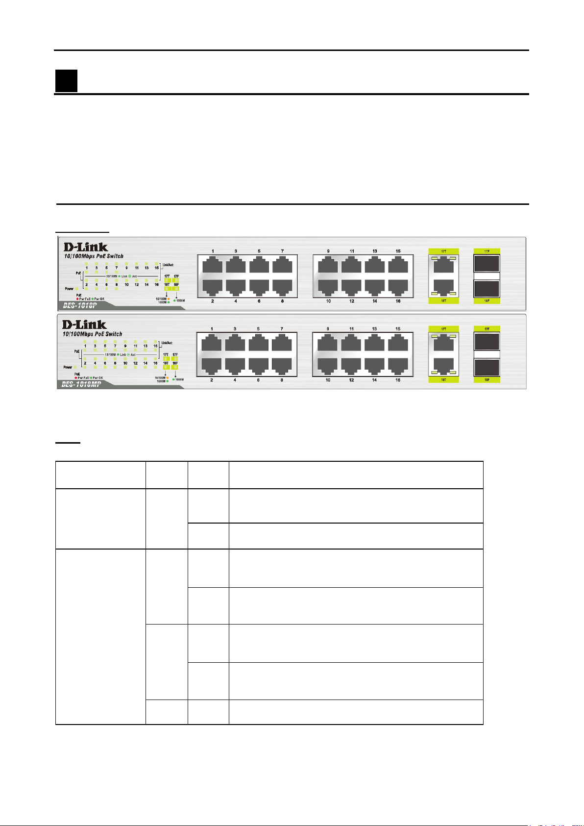
Product Outlook
Front Panel
LEDs
10/100/1000BASE
-T/SFP Ports
(Ports 17 to 18)
Figure 1 – DES-1018P/MP Front Panel
light
light
light
established.
33
Page 6

D-Link Switch User Manual
Link/Act/Speed
Green
Solid
When there is a secure connection (or link) to 10/100
Blinking
When there is reception or transmission of data
Off
Off
No link
PoE
Green
Solid
The port is successfully connected to a PoE device and
Red
Solid
The PoE port has failed, possibly due to:
Off
Light off
No connection to a PoE device
‧
10/100 Mbps Ports
(Ports 1 to 16)
Ports 1 to 8 for
DES-1018P
orts 1 to 16 for
P
DES-1018MP
light
light
light
Mbps Ethernet device at any of the ports.
occurring at 10/100 Mbps.
is powering the device properly.
1. PoE total power budget shortage.
2.Over current: Exceeds the power current of powered
device's classification.
3.Short circuit: An intentional short circuit has be
per
formed on a powered device.
en
Rear Panel
Po
Power Cord Retainer Slot: Connects the power cord retainer to the unit.
Switch GND: Connect a grounding wire to electrically ground the unit.
Figure 2 – DES-1018P/MP Rear Panels
wer Cord Input: Connects the power cord.
Kensington Security Slot
4
Page 7

D-Link Switch User Manual
DES-1018P/MP has been giving customers the best option for physical security through a Kensington
Security Slot in the rear panel. The Kensington Security Slot adds value to DES-1018P/MP by offering
customers a simple, built-in security solution.
Grounding the Switch
This section describes how to connect the Switch to ground. You must complete this procedure before
powering on your Switch.
Required Tools and Equipment
‧ Ground screws (included in the accessory kit): One M4 x 6 mm (metric) pan-head screw
‧ Ground cable (not included in the accessory kit): The grounding cable should be sized according to local
and national installation requirements. Depending on the power supply and system, a 12 to 6 AWG
copper conductor is required for U.S installation. Commercially available 6 AWG wire is recommended.
The length of the cable depends on the proximity of the Switch to proper grounding facilities.
‧ A screwdriver (not included in the accessory kit)
The following steps let you connect the switch to a protective ground:
1. Verify if the system power is off.
2. Use the ground cable to place the #8 terminal lug ring on top of the ground-screw opening.
3. Insert the ground screw into the ground-screw opening.
4. Using a screwdriver, tighten the ground screw to secure the ground cable to the Switch.
5. Attach the terminal lug ring at the other end of the grounding cable to an appropriate grounding stud
or bolt on the rack where the Switch is being installed.
6. Verify if the connections at the ground connector on the Switch and the rack are securely attached.
55
Page 8

D-Link Switch User Manual
2 Hardware Installation
This chapter provides unpacking and installation information for the D-Link DES-1018P/MP.
Step 1: Unpacking
Open the shipping carton and carefully unpack the contents. Please consult the packing list to make sure all
items are present and undamaged.
One D-Link DES-1018P/MP device
One power cord
One power cord retainer
One rack-mount kit and rubber feet
One Multi-lingual Quick Installation Guide
If any item is found missing or damaged, please contact your local retailer for replacement.
Step 2: Switch Installation
Please follow the steps below to set up the Switch:
nstall the DES-1018P/MP in a cool and dry place. Refer to the Technical Specifications for the
1. I
acceptable operating temperature and humidity ranges.
2. Install the Switch in a site free from strong electromagnetic source, vibration, dust, and direct
sunlight.
3. Leave at least 10 cm of space at the left and right-hand side of the Switch for ventilation.
4. Visually inspect the power jack and make sure that it is fully secured to the power adapter.
Step 3: Mounting the Switch on a Rack
The DES-1018P/MP can easily be mounted on a rack. Two mounting ears are provided for this purpose.
Make sure that the front panel is exposed in order to view the LEDs. Please refer to the following illustrations:
Mounting the Switch to a Rack
6
Page 9

D-Link Switch User Manual
ttach the ears to each side of the Switch, using the screw-holes located on the side of the device.
1. A
2. Firmly attach the ears to the rack as shown. Please follow the usual safety precautions for rackmountable products.
Attaching the Rubber Feet
Use the provided rubber feet. Position and apply rubber feet to the underside of the DES-1018P/MP Switch.
Attaching the Rubber Feet
Provide for Adequate Ventilation
CAUTION: Do not place any devices on top of the Switch, or place the
Switch on top of any device or object that will block the free flow of air
through the ventilation slots on the sides, top, and bottom of the Switch’s
case. In addition, care should be taken not to place the Switch next to, on
top of, or underneath any device that generates a significant amount of
heat. For the Switch to perform at its optimal level, the Switch must have
adequate ventilation to prevent the Switch from overheating and becoming
damaged.
Step 4: Power on the Switch
To power on the Switch, plug in the female connector of the provided power cord into this socket, and the
male side of the cord into a suitable power source.
After the Switch is powered on, the LED indicators will blink briefly while the system resets.
Power Failure
As a precaution, in the event of a power failure, unplug the Switch. When power is resumed, plug the Switch
back in.
Step 5: Connecting the Switch
Users can attach IEEE 802.3af compliant devices to the PoE ports on the DES-1018P/MP by plugging in an
Ethernet cable.
• Switch to End Node
• Switch to Hub or Switch
• Connecting to a Server
77
Page 10

D-Link Switch User Manual
NOTE: UTP (Unshielded Twisted Pair) Ethernet
radio frequencies.
NOTE: All Ethernet ports auto-detect MDI/MDIX, port
speed (10, 100, 1000 Mbps) and duplex of the device
connected to the Switch.
Cable Quality
For all connections to the Switch, use these rules for cable selection:
• For connections to 10BASE-T and 100BASE-TX devices, use Category 5 or 5e UTP/STP cable.
• For connections to 100BASE-TX and 1000BASE-T devices, use Category 5e or better UTP/STP cable.
All 1000BASE-T connections will operate in full duplex mode.
cabling is adequate for most small office environments.
More expensive STP (Shielded Twisted Pair) can also
be used, but is generally only needed when there will
be risk of strong electromagnetic interference due to
Connect to an End Node
End nodes include PCs outfitted with a 10, 100 or 1000 Mbps RJ-45 Ethernet/Fast Ethernet Network
Interface Card (NIC) and Ethernet-ready routers. Use standard Ethernet cables to connect the Switch to end
nodes. The Switch port will automatically adjust to the hardware characteristics (MDI/MDIX, speed, duplex)
of the device to which it is connected.
Observe the guidelines for cable quality stated at the beginning of this section. The Link/Act/Speed LEDs
for ports 1 to 16 lights green when the link is valid. The LEDs for ports 17 to 18 lights up amber at 10/100
Mbps and green at 1000 Mbps.
Connect to a Hub or Switch
Switch connected to an end node
Connect to another switch or hub
8
Page 11

D-Link Switch User Manual
Observe the guidelines for cable quality stated at the beginning of this section. The Link/Act/Speed LEDs
for ports 1 to 16 light up green when the link is valid. The LEDs for ports 17 to 18 light up amber at 10/100
Mbps and green at 1000 Mbps.
Connect to Network Backbone or Server
Ports 17 to 18 may be used to uplink the Switch to a network backbone or network server. When linking to a
1000BASE-T device, the port operates in full duplex mode.
Connection to a Server
O
bserve the guidelines for cable quality stated at the beginning of this section. The Link/Act/Speed LEDs
for ports 1 to 16 lights green when the link is valid. The LEDs for ports 17 to 18 lights up amber at 10/100
Mbps and green at 1000 Mbps.
99
Page 12

D-Link Switch User Manual
3 Understanding the Switch Features
PoE Rule
DES-1018P/MP supports many PoE features to guarantee the safety and stability of its PoE power supply.
P
oE Power Budget: DES-1018P/MP has set a limitation of maximum PoE power supply at 80/246.4 (DES-
1018P/MP) watts to protect the Switch and to stabilize the power being transmitted to the PoE devices.
Guard Band: DES-1018P/MP has reserved a 3-watt Guard Band to prevent the power supply from
exceeding the PoE power budget. When the current PoE output has reached 80 or 246.4 watts, the Power
Max LED will light up and the Switch will check the priority of each PoE port. In the meantime, if a new PoE
device is connected, the Switch will cut off the power of the port with a higher port number.
Power Saving
DES-1018P/MP supports IEEE802.3az Energy Efficient Ethernet, which will constantly detect if there is data
being transmitted and will put ports in sleep mode accordingly.
10
Page 13

D-Link Switch User Manual
Appendix A - Technical Specifications
Hardware Specifications
Key Components / Performance
Switching Capacity: 7.2 Gbps
Max. Forwarding Rate: 5.36 Mpps
Forwarding Mode: Store-and-forward
Packet Buffer memory: 384 Kbytes
Port Functions
DES-1018P: 8 10/100 Mbps PoE, 8 10/100 Mbps, and 2 10/100/1000BASE-T/SFP combo ports and
DES-1018MP: 16 10/100 Mbps PoE, and 2 10/100/1000BASE-T/SFP combo ports are compliant with
the following standards:
IEEE 802.3
IEEE 802.3u
IEEE 802.3x (Full-duplex flow control)
IEEE 802.3z
IEEE 802.3az
IEEE 802.3af
Physical & Environment
Dimensions: 280 mm x 210 mm x 44 mm
Internal Power Supply AC input: 100~240 VAC, 50/60Hz
Acoustic: DES-1018P: 38dB, DES-1018MP: 36.8 dB(A) at low speed, 51.8 dB(A) at high speed
Operation Temperature: 0~40°C
Storage Temperature: -40~70°C
Operation Humidity: 0%~95% RH
Storage Humidity: 0%~95% RH
Emission (EMI) Certifications
FCC class A
CE Class A
VCCI Class A
C-Tick
CCC
BSMI
Safety Certifications
cUL, LVD
CB
CCC
BSMI
Features
General Features
Surge protection
Supports up to 8k MAC addresses
PoE Features
IEEE 802.3af compliant
Supplies up to 15.4 watts power per port.
Total PoE budget: 80 watts (DES-1018P), 246.4 watts (DES-1018MP) per PoE port.
1111
Page 14

 Loading...