

Page 1

D-Link ™ DES-1024D
24-Port 10/100Mbps
Ethernet Switch
Manual
Page 2

TABLE OF CONTENTS
About This Guide ......................................................... 1
PURPOSE ..........................................................................................1
TERMS/USAGE .................................................................................1
OVERVIEW OF THIS USER’S GUIDE................................................1
Introduction .................................................................. 2
FAST ETHERNET TECHNOLOGY.....................................................2
SWITCHING TECHNOLOGY .............................................................3
FEATURES ........................................................................................4
IEEE
801.1P AND QOS…...….……………………………………5
Unpacking and Setup....................................................4
UNPACKING .....................................................................................7
SETUP ...............................................................................................7
DESKTOP INSTALLATION................................................................8
RACK MOUNTING............................................................................8
Identifying External Components............................... 10
FRONT PANEL................................................................................10
REAR PANEL..................................................................................11
Technical Specifications.............................................12
Technical Specifications.............................................13
ii
Page 3

ABOUT THIS GUIDE
Congratulations on your purchase of the DES-1024D 24-port
10/100Mbps Fast Ethernet Switch. This device integrates 100Mbps
Fast Ethernet and 10Mbps Ethernet network capabilities into one
highly flexible solution.
Purpose
This guide discusses how to install your DES-1024D.
Terms/Usage
In this guide, the term “Switch” (first letter upper case) refers to your 24-port
10/100Mbps Fast Ethernet Switch, and ”switch” (first letter lower case)
refers to other Ethernet switches.
Overview of this User’s Guide
Introduction. Describes the Switch and its features.
Unpacking and Installation. Helps you get started with the basic installation
of the Switch.
Identifying External Components. Describes the front panel, rear panel and
LED indicators of the Switch.
Technical Specifications. Lists the technical (general, physical and
environmental, and performance) specifications of the Switch.
1
Page 4

INTRODUCTION
This chapter describes the features of the DES-1024D and some background
information about Ethernet/Fast Ethernet switching technology.
Fast Ethernet Technology
Ethernet, along with its speedier counterpart Fast Ethernet, is the
most popular networking standard in use today. 100BaseT Fast
Ethernet is an extension of the 10BaseT Ethernet standard,
designed to raise the data transmission capacity of 10BaseT from
10Mbits/sec to 100Mbits/sec. An important strategy incorporated by
100BaseT is its use of the Carrier Sense Multiple Access with
Collision Detection (CSMA/CD) protocol - which is the same
protocol that 10BaseT uses - because of its ability to work with
several different types of cable, including basic twisted-pair wiring.
Both of these features play an important role in network
considerations, and they make 100BaseT an attractive migration
path for those networks based on 10BaseT. Since the 100Mbps Fast
Ethernet is compatible with all other 10Mbps Ethernet
environments, it provides a straightforward upgrade and takes
advantage of the existing investment in hardware, software, and
personnel training.
2
Page 5

Switching Technology
Switching is a cost-effective way of increasing the total network capacity
available to users on a LAN. If an Ethernet network begins to display
symptoms of congestion, low throughput, slow response times, and high rates
of collision, installing a switch to an network can preserve much or all of the
existing network's cabling and workstation interface card infrastructure while
still greatly enhancing the throughput for users. A switch is a viable solution
even if demanding applications, such as multimedia production and video
conferencing, are on the horizon. The most promising techniques, as well as
the best return on investment, could well consist of installing the right
mixture of Ethernet switches.
A switch increases capacity and decreases network loading by dividing a
local area network into different LAN segments. Dividing a LAN into
multiple segments is one of the most common ways of increasing available
bandwidth. If segmented correctly, most network traffic will remain within a
single segment, enjoying the full-line speed bandwidth of that segment.
Switches provide full-line speed, dedicated to bandwidth for all connections.
This is in contrast to the hubs, which use the traditional shared networking
topology, where the connected nodes contend for the same network
bandwidth. When two switching nodes are communicating, they are
connected with a dedicated channel between them, so there is no contention
for network bandwidth with other nodes. As a result, the switch reduces
considerably the likelihood of traffic congestion.
For Fast Ethernet networks, a switch is an effective way of eliminating the
problem of chaining hubs beyond the “two-repeater limit.” A switch can be
used to split parts of the network into different collision domains, making it
possible to expand your Fast Ethernet network beyond the 205-meter network
diameter limit for 100BASE-TX networks. Switches supporting both
traditional 10Mbps Ethernet and 100Mbps Fast Ethernet are also ideal for
bridging between the existing 10Mbps networks and the new 100Mbps
networks.
Switching LAN technology is a marked improvement over the previous
generation of network hubs and bridges, which were characterized by higher
3
Page 6

latencies. Routers have also been used to segment local area networks, but
the cost of a router, the setup and maintenance required make routers
relatively impractical. Today switches are an ideal solution to most kinds of
local area network congestion problems.
Features
The DES-1024D is a high-performance switch designed specifically for
environments where traffic on the network and the number of users increase
continuously.
24-port 10/100BASE Ethernet Switch with RJ-45 connectors
Supports Auto-negotiation of speed and duplex modes for each
port
Supports Auto-MDI/MDI-X on each port, eliminating the need for
cross over cables or uplink ports
Wire-speed reception and transmission
Store-and-Forward switching method
Integrated address Look-Up Engine, supports 8K MAC addresses
Supports 1.25 Mbits RAM for data buffering
Front-panel diagnostic LEDs
IEEE 802.3x flow control for full-duplex
Back pressure flow control for half-duplex
IEEE 802.1p Priority support
IEEE802.1P AND Q OS
The DES-1024D Switches support 802.1p priority queuing Quality of Service.
4
Page 7
The implementation of QoS (Quality of Service) and benefits of using 802.1p
priority queuing are described here.
Advantages of QoS
QoS is an implementation of the IEEE 802.1p standard that allows network
administrators a method of reserving bandwidth for important functions that
require a large bandwidth or have a high priority, such as VoIP (voice-over
Internet Protocol), web browsing applications, file server applications or
video conferencing. Not only can a larger bandwidth be created, but other
less critical traffic can be limited, so bandwidth can be saved. The Switch
has separate hardware queues on every physical port to which
packets from various applications are mapped to and assigned a
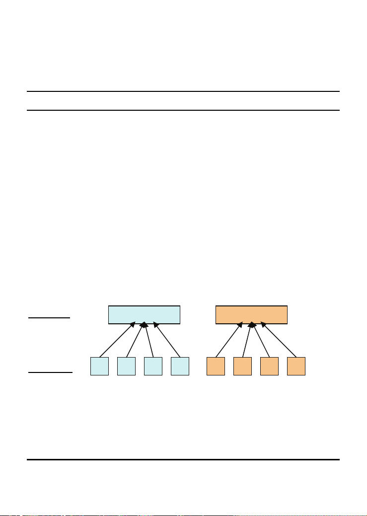
priority. The illustration below shows how 802.1P priority queuing
is implemented on the Switch. The eight IEEE 802.1P priority
levels defined by the standard are mapped to the two class queues
used in the Switch.
2 Priority Queues
Queues:
Priority:
0
Class-0
1 4 72 3 5 6
Class-1
5
Page 8

Mapping QoS on the Switch
The picture above shows the default priority setting for the Switch. Class-1
has higher priority than Class-0 on the Switch. In order to implement QoS,
the user is required to instruct the Switch to examine the header of a packet to
see if it has the proper identifying tag tagged. Then the user may forward
these tagged packets to designated queues on the Switch where they will be
emptied, based on priority.
"The DUT support strict mode for 802.1p QoS. The untagged pkt will follow
the priority 0 to work (i.e. class 0)."
Understanding QoS
The Switch has two priority queues labeled 1 (higher queue), and 0 (lower
queue). The eight priority tags, specified in IEEE 802.1p are mapped to the
Switch's priority tags as follows:
Priority 0 is assigned to the Switch's Q0 queue.
Priority 1 is assigned to the Switch's Q0 queue.
Priority 2 is assigned to the Switch's Q0 queue.
Priority 3 is assigned to the Switch's Q0 queue.
Priority 4 is assigned to the Switch's Q1 queue.
Priority 5 is assigned to the Switch's Q1 queue.
Priority 6 is assigned to the Switch's Q1 queue.
Priority 7 is assigned to the Switch's Q1 queue.
The Switch uses strict priority for Scheduling. Strict priority-based scheduling,
any packets residing in the higher priority queues are transmitted first.
6
Page 9

UNPACKING AND SETUP
Unpacking
Open the shipping cartons of the DES-1024D and carefully unpack its
contents. The carton should contain the following items:
One DES-1024D 24-port 10/100Mbps Fast Ethernet Switch
One AC power cord
Four rubber feet to be used for shock cushioning
Screws and two mounting brackets
Quick Installation Guide
Manual
If any item is found missing or damaged, please contact your local reseller
for replacement.
Setup
The setup of the DES-1024D can be performed by using the following steps:
1. The surface must support at least 11 lbs (5 kg).
2. The power outlet should be within 6 feet (1.42 meters) of the
device.
3. Visually inspect the power cord and see that it is secured fully
to the AC power outlet.
4. Make sure that there is adequate ventilation around the
Switch.
5. Do not place heavy objects on the Switch.
7
Page 10
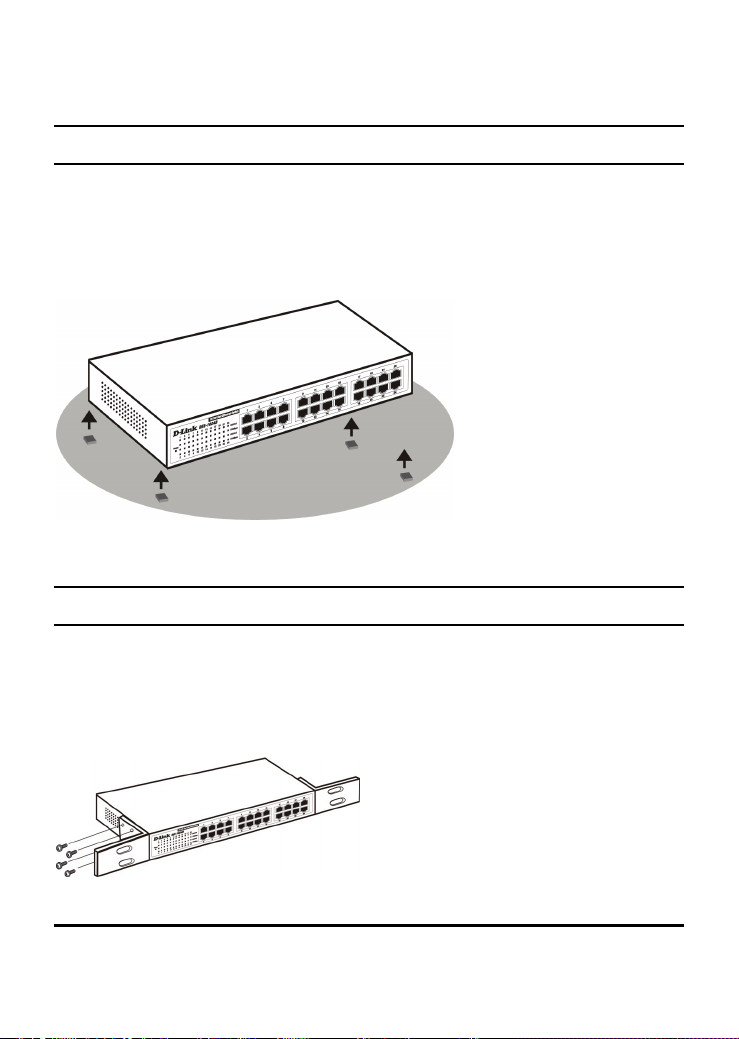
Desktop Installation
When installing the DES-1024D on a desktop or shelf, the rubber feet
included with the device should be attached first, to minimize scratching or
scarring of the surface on which the Switch is placed. Attach these
cushioning feet on the bottom at each corner of the device. Allow enough
ventilation space between the device and the objects around it.
Fast Ethernet Switch installed on a Desktop or Shelf
Rack Mounting
The DES-1024D can be mounted in an EIA standard-size 19-inch rack, in a
wiring closet with other equipment. Attach the mounting brackets on each
side of the Switch’s front panel (as shown in the illustration below), and
secure them with the screws provided.
Attaching the mounting brackets to the Switch
8
Page 11

Installing the Switch in an equipment rack
9
Page 12

IDENTIFYING EXTERNAL COMPONENTS
Front Panel
The figure below shows the front panels of the switch.
24-port 10/100Mbps Fast Ethernet Switch
LED Indicator Panel
Refer to the next chapter for detailed information about each of the switch’s
LED indicators.
Power (PWR)
This green LED indicator illuminates when the switch is receiving power;
otherwise, it is off.
Link / Activity
This green LED indicator illuminates when the port is connected to a Fast
Ethernet or Ethernet station; the indicator blinks when transmitting or
receiving data.
10
Page 13

100Mbps (green)
This green LED indicator illuminates when the port is connected to a
100Mbps Fast Ethernet station. The LED does not illuminate when the port is
connected to 10Mbps Ethernet station.
Twisted-Pair Ports
These ports support automatic MDI/MDI-X crossover detection function
providing true ‘plug and play’ connectivity, which eliminates the need for
crossover cables or uplink ports. Any port can be simply plugged to a server,
workstation, or hub using the usual straight-through, twisted-pair cable.
Rear Panel
11
AC Power Connector
Page 14

TECHNICAL SPECIFICATIONS
General
IEEE 802.3 10BASE-T Ethernet
Standards
Protocol CSMA/CD
Data Transfer
Rate
Topology Star
Network Cables
Number of
Ports
Physical and Environmental
AC inputs 100 to 300 VAC, 50 or 60 Hz internal universal power supply
Power
Consumption
Temperature
Humidity Operating: 10% ~ 90%, Storage: 5% ~ 90%
Dimensions Width: 11.02 in. (280mm)
EMI: FCC Class A, ICES-003 Class A, CE Class A, VCCI Class A
Safety cUL
IEEE 802.3u 100BASE-TX Fast Ethernet
IEEE 802.1p Compliance
Ethernet: 10Mbps (half duplex), 20Mbps (full-duplex)
Fast Ethernet: 100Mbps (half duplex), 200Mbps (full- duplex)
10BASET: 2-pair UTP Cat. 3,4,5, EIA/TIA- 568 100-ohm STP
100BASE-TX: 2-pair UTP Cat. 5, EIA/TIA-568 100-ohm STP
24 x 10/100Mbps Auto-MDI/MDI-X ports
9.8 watts. (max.)
Operating: 0° ~ 40° C (32º to 104º F), Storage: -10° ~ 70° C
(14º to 158º F)
Depth: 7.09 in. (180mm)
Height: 1.73 in. (44mm)
12
Page 15

TECHNICAL SPECIFICATIONS
Performance
Transmits
Method:
RAM Buffer: 1.25 MBits per device
Filtering
Address Table:
Packet Filtering/
Forwarding
Rate:
MAC Address
Learning:
Store-and-forward
8K entries per device
10Mbps Ethernet: 14,880/pps
100Mbps Fast Ethernet: 148,809/pps
Automatic update
13
Page 16

DES-1024D de D-LinkMC
24-Ports 10/100Mbps
Commutateur Ethernet
Guide d’utilisation
Page 17

TABLE DES MATIÈRES
Concernant ce guide ..................................................... 1
OBJET................................................................................................1
CONDITIONS/USAGE .........................................................................1
SURVOL DE CE GUIDE D’UTILISATION ..............................................1
Introduction .................................................................. 2
TECHNOLOGIE FAST ETHERNET .......................................................2
TECHNOLOGIE DE COMMUTATION....................................................3
CARACTÉRISTIQUES..........................................................................4
IEEE802.1P ET QS ...........................................................................5
Déballage et installation ............................................... 7
DÉBALLAGE......................................................................................7
INSTALLATION..................................................................................7
INSTALLATION SUR UN PUPITRE OU UNE TABLETTE.........................8
MONTAGE SUR BÂTI .........................................................................8
Identification des composants externes...................... 10
PANNEAU AVANT............................................................................10
PANNEAU ARRIÈRE .........................................................................11
Caractéristiques techniques ........................................ 12
Caractéristiques techniques ........................................ 13
ii
Page 18

CONCERNANT CE GUIDE
Félicitations pour votre achat du commutateur Fast Ethernet 24 ports
10/100 Mb/s DES-1024D. Cet appareil intègre les possibilités
réseautiques de Fast Ethernet 100 Mb/s et Ethernet 10 Mb/s en une
solution hautement flexible.
Objet
Ce guide traite de l’installation de votre DES-1024D.
Conventions/Usage
Dans ce guide, le terme « Commutateur » (avec majuscule) se rapporte à
votre commutateur
«
commutateur » (sans majuscule) se rapporte à d’autres
commutateurs Ethernet.
Survol de ce guide d’utilisation
Introduction. Décrit le Commutateur et ses caractéristiques.
Déballage et installation. Vous aide à entamer l’installation de base du
Commutateur.
Identification des composants externes. Décrit le panneau avant, le panneau
arrière et les voyants DEL du Commutateur.
Caractéristiques techniques. Énumère les spécifications techniques
(générales, physiques et environnementales et de performance) du
Commutateur.
Fast Ethernet 24 ports 10/100 Mb/s tandis que
1
Page 19

INTRODUCTION
Ce chapitre décrit les caractéristiques du DES-1024D et donne des
renseignements de base au sujet de la technologie de commutation Ethernet/
Fast Ethernet.
Technologie Fast Ethernet
Ethernet, ainsi que son équivalent plus rapide Fast Ethernet, est la
norme réseautique d’usage la plus répandue actuellement. Fast
Ethernet 100BaseT est une extrapolation, de 10 Mb/s à 100 Mb/s,
de la norme Ethernet 10BaseT. L’usage du protocole CSMA/CD
(Carrier Sense Multiple Access with Collision Detection) – le même
protocole que celui utilisé par 10BaseT – constitue une importante
stratégie incorporée à 100BaseT en raison de sa capacité de
fonctionner avec de nombreux types de câbles, dont le câble de base
à paire torsadée. Ces deux caractéristiques jouent un rôle
important dans les considérations de réseau et font de 100BaseT
une voie de migration intéressante pour les réseaux basés sur
10BaseT. Puisque Fast Ethernet 100 Mb/s est compatible avec tous
les autres environnements Ethernet 10 Mb/s, il fournit une mise à
niveau simple et tire profit de l’investissement actuel en
équipement, logiciel et formation du personnel.
2
Page 20

Technologie de commutation
La commutation est une méthode rentable d’augmenter la capacité globale du
réseau offerte aux utilisateurs d’un réseau local. Lorsqu’un réseau Ethernet
commence à montrer des signes de congestion, débit faible, temps réponse
lent et taux de collision élevé, l’installation d’un commutateur peut préserver
une partie importante ou même tout le câblage existant et l’infrastructure des
cartes d’interface des postes de travail et améliorer grandement le débit pour
les usagers. Un commutateur est une solution viable même lorsque des
applications exigeantes comme la production multimédia et la téléconférence
sont à l’horizon. L’installation de la combinaison appropriée de
commutateurs Ethernet pourrait bien constituer la technique la plus
prometteuse, de même que le meilleur rendement du capital investi.
Un commutateur augmente la capacité et réduit la charge réseau en divisant
un réseau local en différents segments de réseau local. La segmentation du
réseau local est un des moyens les plus courants d’augmenter la bande
passante. Si correctement divisé, le gros du trafic réseau demeurera à
l’intérieur d’un même segment et profitera de la pleine largeur de bande de ce
segment.
Les commutateurs fournissent une vitesse pleine ligne, dédiée au débit pour
toutes les connexions. Ceci, en opposition aux concentrateurs qui utilisent la
topologie réseautique partagée classique où les nœuds connectés se font
concurrence pour la même bande passante. Lorsque deux nœuds commutés
sont en communication, ils sont reliés par un canal dédié, de sorte qu’il n’y a
aucun conflit de bande passante avec les autres nœuds. Le commutateur
réduit ainsi considérablement la probabilité de congestion.
Pour les réseaux Fast Ethernet, un commutateur est un moyen efficace
d’éliminer le problème de l’enchaînement des concentrateurs au-delà de la
« limite des deux répéteurs ». Un commutateur peut servir à diviser des
parties du réseau en différents domaines de collision, rendant possible
l’extension de votre réseau Fast Ethernet au-delà de la limite de 205 mètres
des réseaux 100BASE-TX. Les commutateurs fonctionnant en Ethernet
10 Mb/s traditionnel tout autant qu’en Fast Ethernet 100 Mb/s sont aussi tout
3
Page 21

indiqués pour faire le pont entre les réseaux à 10 Mb/s existants et les
nouveaux réseaux à 100 Mb/s.
La technologie de réseau local commuté est une amélioration marquée par
rapport à la génération précédente des concentrateurs réseau et des ponts qui
se caractérisaient par des attentes plus grandes. Les routeurs ont aussi servi à
segmenter les réseaux locaux, mais le coût d’un routeur, l’installation et
l’entretien requis les rendent relativement peu pratiques. Aujourd’hui, les
commutateurs sont une solution idéale à la plupart des problèmes de
congestion des réseaux locaux.
Caractéristiques
Le DES-1024D est un commutateur haute performance conçu expressément
pour les environnements où le trafic du réseau et le nombre d’usagers
augmentent sans arrêt.
Commutateur Ethernet 10/100BASE 24 ports avec connecteurs
RJ-45
Supporte l’autonégociation de la vitesse et des modes duplex pour
chaque port
Supporte auto MDI/MDI-X sur chaque port, éliminant le besoin de
câbles inverseurs ou de ports de liaison montante
Réception et transmission à vitesse filaire
Commutation en mode différé (Store and Forward)
Moteur de recherche d’adresses intégré supporte 8000 adresses
MAC
Supporte 1,25 Mb de mémoire vive en tampon de données
Voyants DEL de diagnostic au panneau avant
Contrôle de flux IEEE 802.3x pour le duplex intégral
Contrôle de flux de contre-pression pour le semi-duplex
Supporte la priorité IEEE 802.1p
4
Page 22

IEEE 802.1P ET QS
Le commutateur DES-1024D fonctionne avec la mise en attente de priorité
Qualité de service 802.1p. La mise en œuvre de QS (Qualité de service) et les
avantages d’utiliser la mise en attente de priorité 802.1p sont décrits ici.
Avantages de QS
QS est la mise en œuvre de la norme IEEE802.1p octroyant aux
administrateurs de réseau une méthode pour réserver de la bande passante
aux fonctions importantes qui exigent une grande largeur de bande ou ont une
priorité haute, comme le protocole voix sur IP, les applications de navigation
Web et de serveur de fichiers ou la téléconférence. Non seulement peut-on
créer une bande passante plus large, on peut aussi limiter le trafic moins
important pour économiser de la bande passante. Le Commutateur comprend
des files d’attente d’équipement distinctes sur chaque port, auxquelles des
paquets de différentes applications sont mappés et une priorité est attribuée.
L’illustration ci-dessous montre comment la priorisation en files d’attente
s’articule sur le Commutateur. Les huit niveaux de priorité IEEE 802.1p sont
mappés à une des deux files qu’utilise le Commutateur.
2 files d’attente de priorité
Files :
Priorité :
0
Classe 0
1 4 72 3 5 6
Classe 1
5
Page 23

Mappage de QS sur le commutateur
L’illustration qui précède montre le réglage par défaut du Commutateur. La
classe 1 a une plus haute priorité. Pour exécuter QS, l’utilisateur doit donner
instruction au Commutateur d’examiner l’entête d’un paquet pour repérer le
préfixe d’identification approprié. L’usager peut ensuite transmettre ces
paquets identifiés aux files désignées sur le Commutateur où ils se
déverseront selon la priorité.
"The DUT support strict mode for 802.1p QoS. The untagged pkt will follow
the priority 0 to work (i.e. class 0)."
Comprendre QS
Le Commutateur a deux files de priorité étiquetées 1 (file supérieure) et 0
(file inférieure). Les huit préfixes de priorité identifiés par IEEE 802.1p sont
mappés dans le Commutateur selon ce qui suit :
La priorité 0 est dirigée à la file Q0,
La priorité 1 est dirigée à la file Q0,
La priorité 2 est dirigée à la file Q0,
La priorité 3 est dirigée à la file Q0,
La priorité 4 est dirigée à la file Q1,
La priorité 5 est dirigée à la file Q1,
La priorité 6 est dirigée à la file Q1,
La priorité 7 est dirigée à la file Q1,
Le Commutateur fonctionne strictement sur la base des priorités; les paquets
empilés dans les files de priorité supérieure sont transmis en premier.
6
Page 24

DÉBALLAGE ET INSTALLATION
Déballage
Ouvrez la boîte du DES-1024D et déballez prudemment son contenu. Vous
devriez y retrouver les articles suivants :
Un commutateur Fast Ethernet DES-1024D 10/100 Mb/s 24
ports
Un cordon électrique
Quatre coussinets caoutchoutés pour amortir les chocs
Vis et deux supports de montage
Guide d’installation rapide
Guide d’utilisation
Si l’un ou l’autre de ces articles est manquant ou endommagé, veuillez
contacter votre détaillant pour le remplacement.
Installation
Installez le DES-1024D en suivant ces étapes :
1. La surface doit supporter au moins 5 kg (11 lb).
2. La prise de courant doit être située à moins de 1,42 m (6 pi) de
l’appareil.
3. Inspectez visuellement le cordon électrique et assurez-vous de
son branchement solide à la prise de courant CA.
4. Assurez-vous d’une ventilation adéquate autour du
commutateur.
5. Ne placez pas d’objet lourd sur le commutateur.
7
Page 25

Installation sur un pupitre ou une tablette
Avant d’installer le DES-1024D sur un pupitre ou une tablette, on doit
d’abord fixer les coussinets caoutchoutés à chaque coin sous l’appareil afin
de minimiser les égratignures sur la surface où on le dépose. Il faut aussi
laisser suffisamment d’espace autour de l’appareil pour la ventilation.
Commutateur Fast Ethernet installé sur un pupitre ou une tablette
Montage sur bâti
On peut installer le DES-1024D dans un bâti standard EIA de 19 pouces,
dans une armoire de câblage avec d’autres équipements. Fixez les supports de
montage de chaque côté du panneau avant du commutateur (comme illustré
ci-après) à l’aide des vis fournies.
Fixation des supports de montage au commutateur
8
Page 26

Installation du commutateur dans un bâti
9
Page 27

IDENTIFICATION DES COMPOSANTS EXTERNES
Panneau avant
L’illustration qui suit montre le panneau avant du commutateur.
Commutateur Fast Ethernet 24 ports 10/100 Mb/s
Panneau des voyants DEL
Consultez le chapitre suivant pour des renseignements détaillés sur chaque
voyant DEL du commutateur.
Power (Alimentation)
Ce voyant DEL s’illumine lorsque le commutateur est sous tension, sinon il
est éteint.
Link/Activity (Lien/Activité)
Ce voyant DEL s’allume au vert si le port est connecté à un poste Fast
Ethernet ou Ethernet. La DEL clignote s’il y a activité à ce port, soit
réception ou transmission de données.
10
Page 28

100Mbps (vert)
Ce voyant s’illumine au vert pour indiquer une connexion à un appareil Fast
Ethernet à 100 Mb/s au port. Le voyant est éteint lors de la connexion à un
appareil Ethernet à 10 Mb/s.
Ports à paire torsadée
Ces ports supportent la fonction de détection automatique MDI/MDI-X,
offrant une réelle connectivité « prêt-à rouler », éliminant le besoin de câbles
inverseurs ou de ports de liaison montante. N’importe quel port peut se
connecter à un serveur, un poste de travail ou un concentrateur à l’aide d’un
câble droit torsadé.
Panneau arrière
Raccord d’alimentation CA
11
Page 29

CARACTÉRISTIQUES TECHNIQUES
Générales
IEEE 802.3 10BASE-T Ethernet
Normes
Protocole CSMA/CD
Taux de
transfert de
données
Topologie Star
Câbles réseau
Nombre de
ports
Physiques et environnementales
Entrées AC 100 à 300 V CA, 50 ou 60 Hz alimentation universelle interne
Consommation 9,8 W (max.)
Température En usage : 0° à 40 °C (32° à 104 °F); en entreposage : -10° à
Humidité En usage : 10 % à 90 %; en entreposage : 5 % à 90 %
Dimensions Largeur : 280 mm (11.02 po)
EMI: FCC Classe A, ICES-003 Classe A, CE Classe A, VCCI Classe A
Sécurité cUL
IEEE 802.3u 100BASE-TX Fast Ethernet
IEEE 802.1p Conformité
Ethernet : 10 Mb/s (semi-duplex), 20 Mb/s (duplex intégral)
Fast Ethernet : 100 Mb/s (semi-duplex), 200 Mb/s (duplex
intégral)
10BASET : 2-paires UTP Cat. 3, 4, 5, EIA/TIA-568 100-ohm
STP
100BASE-TX : 2-paires UTP Cat. 5, EIA/TIA-568 100-ohm STP
24 x ports 10/100 Mb/s Auto MDI/MDI-X
70 °C (14° à 158 °F)
Profondeur : 180 mm (7.09 po)
Hauteur : 44 mm (1,73 po)
12
Page 30

CARACTÉRISTIQUES TECHNIQUES
Performance
Méthode de
transmission
Tampon RAM 1,25 Mbits par appareil
Tableau de
filtrage des
adresses :
Filtrage de
paquets/taux de
transfert
Apprentissage
d’adresses
Mode différé (Store-and-forward)
8000 inscriptions par appareil
Ethernet 10 Mb/s : 14 880/pps
Fast Ethernet 100 Mb/s : 148 809/pps
Mise à jour automatique
13
Page 31

Page 32

Ver. 2.00(CA)
2009/05/15
29071600D1024D4
 Loading...