

D-Link DE-856SC Installation Manual

Specifications
Standard
IEEE 802.3 10BASE-T, 10BASE-FL
10BASE-T RJ-45 Connector
One RJ-45 switch is provided for selecting the type of RJ45 connector as follows:
RJ-45 Switch RJ-45 Type
X position MDI-X
II position M DI
RJ-45 Pin MDI-X type MDI type
1 Rx+ Tx+
2 RX- Tx3 Tx+ Rx+
6 Tx- Rx-
It allows you to make all UTP connections using common
straight-through UTP.
10BASE-T UTP Cable
Cable type: Category 3, 4 or 5
Maximum ca ble dista nce: 100 meters (328 feet)
Fiber Optic Connectors
Two connectors are provided for fiber optic cable
connection. One is labeled "Tx" for transmitting operation.
The other is labeled "Rx" for receiving operation.
Model Converter/T Converter/C Converter/S
Wavelength 850nm 850nm 1300nm
Fiber mode Multimode Multimode Single mode
Connector ST type SC type ST type
Fiber cable*162.5/125µm 62.5/125µm 8/125µm
Cable length 2000 meters 2000 meters 14K meters
Fiber cable*1: Recommended fiber cable
LEDs
Unit LED Power
Port LEDs UTP Link, UTP Rx, Fiber Link, Fiber Rx
(Rx: receiving status)
Environment
Te mperature 0o - 40oC
Humidity 10-90% non condensing
Dimension
74mm x 51mm x 20mm
Power
+12V / 500mA minimum
DC plug type:
Installation
1. Install the media converter with the DC power adapter
provided. ( +12VDC, 500mA)
2. Connect the power adapter cable to the media converter before connecting the adapter to the AC outlet.
3. Do not connect more than two media converters in
series.
General Description
The 10BASE-T/10BASE-FL Ethernet media converter is
designed to be a connection interface between a 10BASE-T
Ethernet UTP cable and 10BASE-FL fiber ca ble with no
increasing on the hop count in the network. It features a
RJ-45 connector and a pair of fiber optic connectors. This
guide covers the following three models to support
different fiber cables as follows:
Converter/T UTP to multimode fiber with ST connectors
Converter/C UTP to multimode fiber with SC connectors
Converter/S UTP to single mode fiber with ST connectors
Installation Guide
10BASE-T/10BASE-FL
Ethernet Media Converters
Interpreting LED Indicators
LED Status State Interpretation
Power Power status On Converter is on.
Of f Converter is off.
Link Fiber link On The fiber link is ok.
Off No link or the link is faulty.
Rx Receiving status Blink Receiving is in operation.
Off No fiber receiving.
Link UTP link On The UTP link is ok.
Off No link or the link is faulty.
Rx Receiving status Blink Receiving is in operation.
Off No fiber receiving.
The information contained in this document is subject to change
without prior notice.
TRADEMARKS
Ethernet is a registered trademark of Xerox Corp.
WARNING:
This equipment has been tested and found to comply with the
limits for a Class A digital device, pursuant to Part 15 of the FCC
Rules. These limits are designed to provide reasonable protection
against harmful interference when the equipment is operated in a
commercial environment. This equipment generates, uses, and
can radiate radio frequency energy and if not installed and used
in accordance with the instruction manual may cause harmful
interference in which case the user will be required to correct
the interference at his own expense.
NOTICE:
(1) The changes or modifications not expressively approved by
the party responsible for compliance could void the user's
authority to operate the equipment.
(2) Shielded interface cables and AC power cord, if any, must
be used in order to comply with the emission limits.
CISPR A COMPLIANCE:
This device complies with EMC directive of the European
Community and meets or exceeds the following technical
standard.
EN 55022 - Limits and Methods of Measurement of Radio
Interference Characteristics of Information Technology
Equipment. This device complies with CISPR Class A.
WARNING: This is a Class A product. In a domestic environment
this product may cause radio interference in which case the
user may be required to take adequate measures.
CE NOTICE
Marking by the symbol CE indicates compliance of this equipment
to the EMC directive of the European Community. Such marking is
indicative that this equipment meets or exceeds the following
technical standards:
EN 55022: Limits and Methods of Measurement of Radio
Interference characteristics of Information Technology
Equipment.
EN 50082/1:Generic Immunity Standard -Part 1: Domestic
Commercial and Light Industry.
EN 60555-2: Disturbances in supply systems caused by
household appliances and similar electrical equipment - Part 2:
Harmonics.
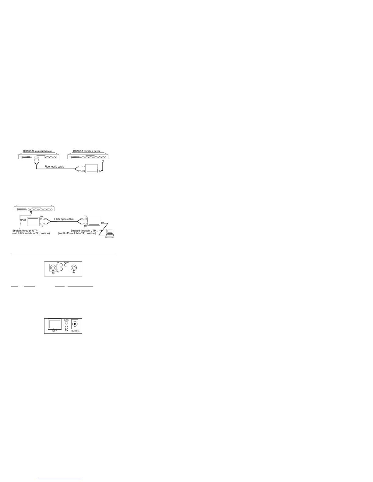
Making Network Connections
The following example illustrates a connection from a
10BASE-T port of one hub to a 10BASE-FL port of another
hub through a media converter.
The following example illustrates a connection from a
10BASE-T port of one hub to a 10BASE-T NIC on a
computer through a media converter.
P/N: 750-011 1-004
 Loading...