

Page 1
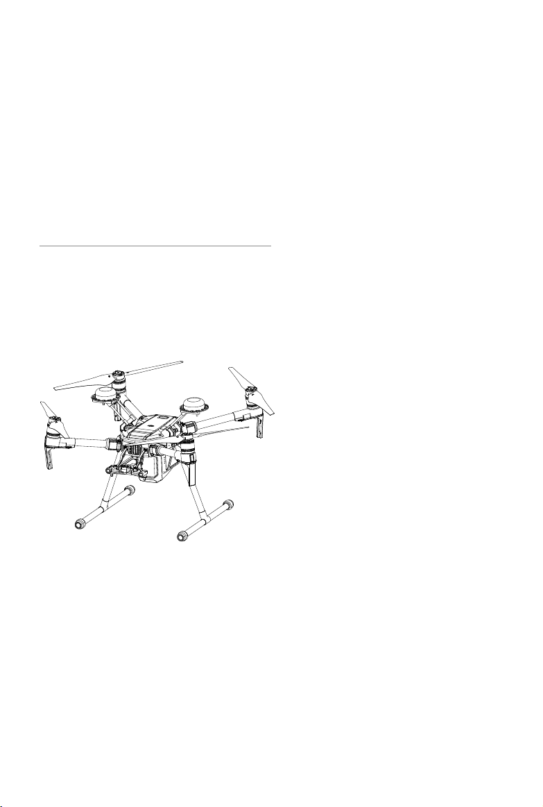
MATRICE 200 SERIES
M210/M210 RTK
User Manual
2017.08
V1.0
Page 2
Searching for Keywords
Search for keywords such as “battery” and “install” to find a topic. If you are using Adobe
Acrobat Reader to read this document, press Ctrl+F on Windows or Command+F on Mac to
begin a search.
Navigating to a Topic
View a complete list of topics in the table of contents. Click on a topic to navigate to that
section.
Printing this Document
This document supports high resolution printing.
Using this manual
Legends
Warning Important Hints and Tips Reference
Before Flight
The following materials have been produced to help users make full use of the MATRICETM 210/210 RTK.
1. In the Box
2. Safety Guidelines and Disclaimer
3. Quick Start Guide
4. Intelligent Flight Battery Safety Guidelines
5. User Manual
Watching all the tutorial videos and reading the Disclaimer before flight is recommended.
Afterwards, prepare for your rst ight by using the Quick Start Guide. Refer to this manual for more
comprehensive information.
Watch the video tutorials
Please watch the tutorial video below to learn how to use Matrice 210/210 RTK correctly
and safely:
http://www.dji.com/matrice-200-series/info#video
Download the DJI GO 4 app
Be sure to use the DJI GOTM 4 app or other apps compatible with DJI aircraft during ight.
Scan the QR code or visit
“https://m.dji.net/djigo4” to download the app.
For the best experience possible, use mobile devices running Android v4.4 or iOS v9.0 or above.
* For increased safety, the ight is restricted to a height of 30 m and distance of 50 m when not connected or logged
into the app during ight, including DJI GO 4 and all apps compatible with DJI aircraft.
Download the DJI Assistant 2
Download and install the ASSISTANTTM 2 before use.
http://www.dji.com/matrice-200-series/info#downloads
2017 DJI All Rights Reserved.
©
2
Page 3

Contents
Product Prole
Introduction
Feature Highlights
Assemble the Aircraft
Preparing the Remote Controller
Aircraft Diagram
Remote Controller Diagram
Aircraft
Flight Controller
Flight Mode
Flight Status Indicator
Vision System and Infrared Sensing System
Return-to-Home (RTH)
Intelligent Flight Modes
Flight Recorder
Attaching and Detaching the Propellers
DJI Intelligent Flight Battery
D-RTK and Datalink Pro
DJI AirSense
Expansion Ports
Remote Controller
Remote Controller Prole
Preparing the Remote Controller
Mounting the Monitor to the Remote Controller
Remote Controller Operations
Dual Remote Controller Mode
Linking the Remote Controller
6
6
6
7
9
11
12
15
15
15
16
17
22
26
31
31
31
37
38
39
42
42
42
44
45
50
52
Gimbal and Camera
Camera
Gimbal
DJI GO 4
Equipment
Editor
SkyPixel
Me
2017 DJI All Rights Reserved.
©
55
55
56
59
59
63
63
63
3
Page 4

Flight
Flight Environment Requirements
Flight Limits and No-Fly Zones
Preight Checklist
Calibrating the Compass
Auto Takeoff and Auto Landing
Stop the Motor Mid-ight
Starting/Stopping the Motors
Flight Test
65
65
65
68
68
69
70
70
71
Appendix
Specications
Aircraft Status Indicator Description
Upgrading the Firmware
Using the Zenmuse XT Gimbal and Camera
Mounting the Upward Gimbal and GPS Module
Dual Downward Gimbals
After-Sales Information
73
73
76
76
77
78
79
82
2017 DJI All Rights Reserved.
©
4
Page 5

Product Prole
This chapter describes the features
of the Matrice 210/Matrice 210 RTK,
shows how to assemble the aircraft,
and contains diagrams of the aircraft
and remote controller with component
explanations.
2017 DJI All Rights Reserved.
©
5
Page 6

Product Prole
Introduction
The Matrice 210/Matrice 210 RTK (M210/M210 RTK) is a powerful aerial imaging system with classleading agility and speed, redundant components for maximum reliability, and new smart features
that make performing complex tasks easy. Gimbal cameras can be easily exchanged to suit your
application's needs. Dual frequency remote controller transmission makes HD video downlink more
stable and efcient. Upgraded With TapFlyTM and ActiveTrackTM ight modes, the aircraft can y
anywhere you tap on screen and track moving subjects effortlessly.
Feature Highlights
The aircraft’s mechanical design, along with quick-release landing gears and folding arms, makes
it easy to transport, store, and prepare for ight. The drone’s new airframe design gives it an IP43
Ingress Protection Rating, in accordance with the global IEC 60529 standard.
Flight Controller: The flight controller has been updated to provide a safer, more reliable flight
experience. A new ight recorder stores critical data from each ight. A system of visual sensors
enhance hovering precision when ying indoors or in environments where GPS is unavailable. Dual
IMUs and barometers design provides redundancy.
HD Video Downlink: The low-latency long range (up to 4.3mi (7km)) HD downlink is powered by an
en hanced version of DJI LIGHTBRIDGETM. Support of 2.4 GHz and 5.8 GHz ensures a more reliable
con nection in environments with more interference.
Camera and Gimbal: The camera unit is now independent from image processor so that you have
the exibility to choose the perfect gimbal and camera system (including ZENMUSETM X5S/X4S/XT*,
and Z30) for each of your application. This means that regardless of which camera you choose,
you have the same powerful processing backing it. The M210/M210 RTK can support a single
upward gimbal or dual downward gimbals.* It is equipped with many expansion ports to broaden
its applications. The M210 RTK has a built-in DJI D-RTKTM, which provides more accurate heading
data for positioning.
Intelligent Flight Battery: The Intelligent Flight Battery features upgraded battery cells and an
advanced power management system. Without a payload, the M210 provides up to 27 minutes of
ight with TB50-M200 batteries and 38 minutes with high-capacity batteries (TB55). The M210 RTK
offers up to 23-minute and 32-minute no-payload ight times with TB50-M200 and high-capacity
batteries, respectively.
* The Zenmuse XT Gimbal Adapter is required when mounting the Zenmuse XT gimbal to the Matrice 200 series
aircraft.
Both DJI GO 4 and DJI Pilot support the Zenmuse X5S, X4S, and Z30. DJI Pilot is required if using the Zenmuse XT.
Gimbals can be purchased separately from the ofcial DJI Online Store. A GPS module is required when using a
single upward gimbal. DO NOT use an upward and downward gimbal simultaneously.
2017 DJI All Rights Reserved.
©
6
Page 7

MATRICE 200 Series User Manual
1
2
3
Assemble the Aircraft
This manual uses the M210 RTK and Zenmuse Z30 as an example to demonstrate setup and usage.
Unfolding the D-RTK Antennas
For the M200 series, only mount the D-RTK antennas to the M210 RTK.
Unfold the D-RTK antennas and tighten the screws.
2
1
Installing the Landing Gears Unfolding the Aircraft
Unfold the frame arm, slide the arm lock to the end of the frame
arm, then rotate it about 90° until the silver line lies within the
range of the icon.
Mounting the Propellers
Propellers
without silver
rings go on
motors without
any marks.
Press the propeller down
onto the mounting plate
and rotate in the lock
direction until secure.
Check that the propellers are secure
before each ight.
Propellers
with silver
rings go on
motors with
the same
color marks.
2017 DJI All Rights Reserved.
©
7
Page 8
MATRICE 200 Series User Manual
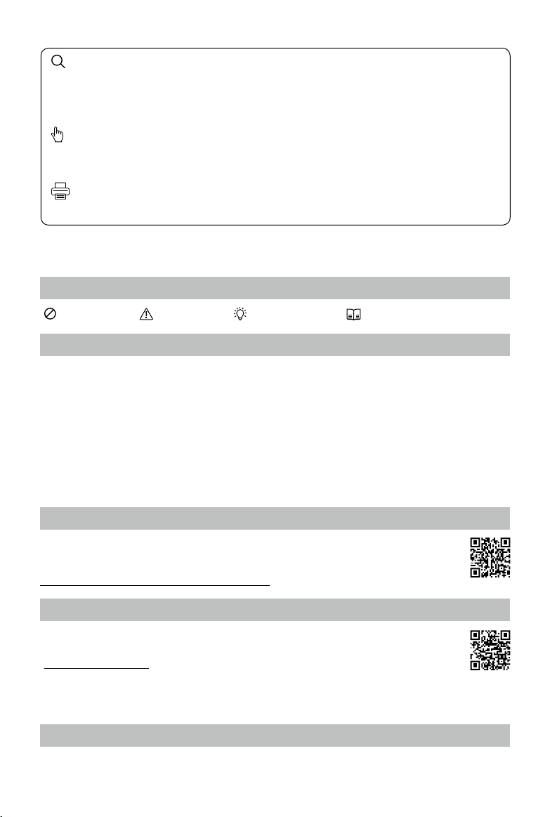
Mounting the Gimbal and Camera
11
Press the gimbal
detachment button
to remove the cover.
Align the white
and red dots and
insert the gimbal.
2
Rotate the gimbal
lock to the locked
position.
3
Make sure to press down the gimbal detachment button when rotating the gimbal lock to
remove the gimbal and camera. The gimbal lock should be fully rotated when removing the
gimbal for the next installation.
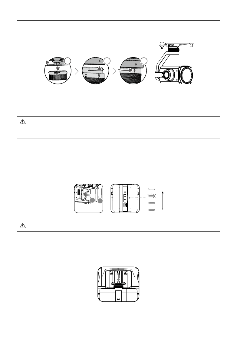
Mounting the Intelligent Flight Batteries
Insert the battery pair.
Press once to check the battery level.
Press once, again, and hold to turn on/off.
High
A
B
Low
Only use battery slot B when using one battery to supply power.
Removing the Intelligent Flight Battery
Make sure to press the battery removal button when removing the battery.
2017 DJI All Rights Reserved.
©
8
Page 9
MATRICE 200 Series User Manual
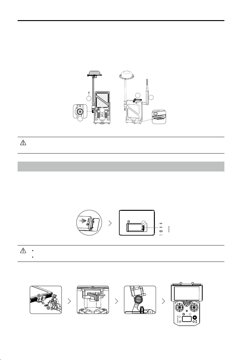
Mounting the D-RTK Ground System
For the M200 series, only mount the D-RTK Ground System to the M210 RTK.
1. Rotate the screws to secure the antenna bracket, and install the battery.
2. Rotate the clamp to secure the battery, and install the Datalink Pro antenna.
3. Install the D-RTK Ground System onto an appropriate tripod.
4
1
3
2
5
1/4"or3/8"
This manual uses the Datalink Pro 900 as an example. Please refer to the D-RTK and
Datalink Pro user guides for more details.
Preparing the Remote Controller
Mounting Monitor and Remote Controller Batteries
CrystalSky monitors and the Cendence remote controller use the same batteries.
Put the battery into the Battery Slot, then slide it to the end until you hear a click.
Press the Battery Release Button before removing the battery.
Press the Battery Level Button once to check the battery level.
Mounting the Monitor to the Remote Controller
A
B
Ensure that Part B is
unlocked. Connect Part
B to Part A.
Lock the Mounting
Bracket.
Use a coin to adjust the
tightness of the tilt axis.
Low
High
2017 DJI All Rights Reserved.
©
9
Page 10
MATRICE 200 Series User Manual
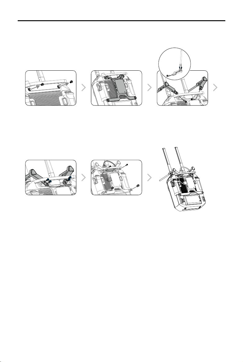
Mounting the Datalink Pro Air System to the Remote Controller
For the M200 series, only mount the Datalink Pro Air System to the M210 RTK remote controller.
M2×8
M3×5
Remove the screws. Afx the Datalink Pro Air System
M2.5×6 M3×12
Attach the clips onto the
mounting board, then connect
the antennas to the Datalink Pro
Air System.
onto the mounting board with
the double-sided adhesive,
then attach the mounting board
onto the back of the remote
controller.
Afx the CAN Hub module to the
mounting board with the doublesided adhesive, then secure the
mounting board using screws.
1/4"
Thread the Datalink Pro antennas
through the clips. Make sure
that the lines of the antennas lie
in the grooves of the mounting
board where the clips attach to
prevent the antennas from being
damaged.
2017 DJI All Rights Reserved.
©
10
Page 11
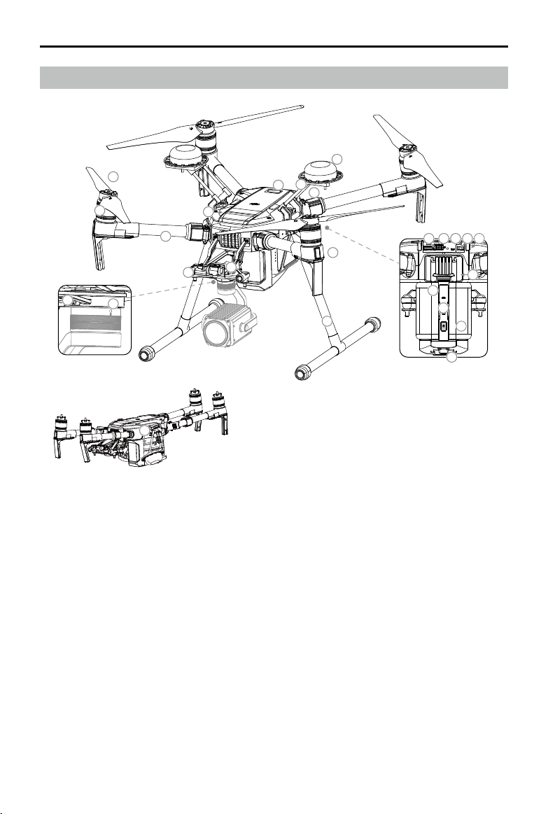
Aircraft Diagram
7
6
MATRICE 200 Series User Manual
14
12
11
13
10
5
2
4
3
25
Folded
1. FPV Camera
2. Forward Vision System
3. DJI Gimbal Connector v2.0 (DGC2.0)
4. Gimbal Detachment Button
5. Frame Arms
6. Motors
7. Propellers
8. ESC LEDs
9. Landing Gears
10. Upward Gimbal Mounting Position
11. Upward Infrared Sensor
12. Aircraft Status Indicator
13. D-RTK Mounting Bracket
15 16 17
18 19
8
1
9
20
21
22
23
24
14. D-RTK Antennas**
15. USB Port
16. Expansion Ports
17. RC/Aircraft Linking
Button and Indicator
18. USB Mode Switch
19. Extended Power Port (XT30)
20. Battery Removal Button
21. Intelligent Flight Batteries
22. Battery Level Indicators
23. Power Button
24. Downward Vision System
25. Micro SD Card Slot
2017 DJI All Rights Reserved.
©
11
Page 12
MATRICE 200 Series User Manual
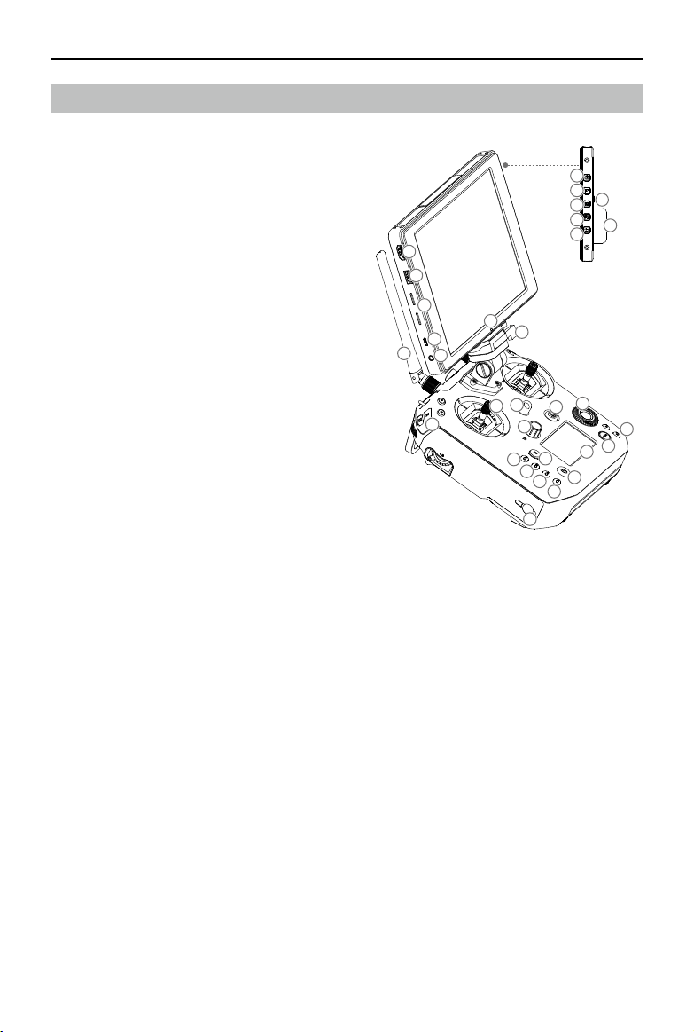
Remote Controller Diagram
[1] HDMI Port
Output HDMI video signal.
[2] USB Port
Supported extended device, e.g. U disk.
[3] Micro SD Card Slot
Provides extra storage space for the dis-
play device, maximum card size is 128 GB.
[4] Micro USB Port
Use a Micro USB cable to connect to the
remote controller when in use, or to the PC
to congure parameters via DJI Assistant 2.
To update aircraft rmware, please use the
USB OTG cable.
[5] Headphone Jack
[6] Light-sensitive Port
Built-in light-sensitive sensor.
[7] Power Button
[8] Custom Button
[9] Setting Button
[10] Custom Button
[11] Back Button
[12] Battery Release Button
[13] WB37 Intelligent Battery
[14] Antennas
Relay aircraft control and video signa.
[15] Monitor Mounting Bracket
Used to mount the DJI CrystalSky monitor.
[16] Control Sticks
Control the orientation and movement of
the aircraft.
[17] Strap Hood
[18] Focus Adjustment Knob
Rotate to set the focal length.
[19] Return-to-Home (RTH) Button
Press and hold to initiate Return to Home
(RTH).
7
8
12
9
10
13
1
2
3
4
14
30
6
15
5
17
16
21
11
28
19
18
25
22
23
24
20
30
29
27
26
[20] Power Port
Connect to the Charger to charge the bat-
tery of the remote controller.
[21] EV Setting Button
Press and rotate the Camera Setting Dial
to set the EV.
[22] Shutter Setting Button
Press and rotate the Camera Setting Dial
to set the shutter speed.
[23] Aperture Setting Button
Press and rotate the Camera Setting Dial
to set the Aperture.
[24] ISO Setting Button
Press and rotate the Camera Setting Dial
to set the ISO.
[25] Pause Button
Press once to exit TapFly, ActiveTrack, or
other Intelligent Flight Modes.
2017 DJI All Rights Reserved.
©
12
Page 13
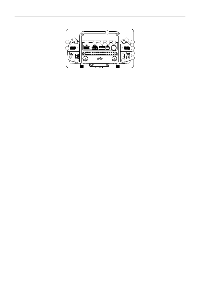
MATRICE 200 Series User Manual
34
31 40
35
33
36 37
38
4545
39
43
4132
42
44
[26] Power Button
Used to turn the Remote Controller on
and off.
[27] Remote Controller Display
Shows information about the aircraft and
camera.
[28] Camera Setting Dial
Works with the EV, Shutter, Aperture and
ISO Settings Buttons to adjust their values.
[29] Customizable Button Settings Menu
Press to set Customizable Button func-
tions in the DJI GO 4 app.
[30] Customizable Buttons (BA-BH)
Customizable through the DJI GO 4 app.
[31] Left Lever
Customizable through the DJI GO 4 app.
[32] Left Dial
Controls gimbal tilt.
[33] Flight Mode Switch
Switch between P-mode, S-mode, and
A-mode.
[34] Handle Bar
[35] USB Port
Connection to mobile device for DJI GO 4
app if used a third party mobile device.
[36] HDMI A Port
HDMI A Port is for video output.
[37] CAN Bus
Used to connect external devices.
[38] Micro USB Port
Used to update rmware.
[39] SDI Port (for Video Output)
Used for video output.
[40] Right Lever
Customizable through the DJI GO 4 app.
[41] Right Dial
Used to control gimbal pan.
[42] Auto Focus Button
Press to focus automatically.
[43] Record Button
Press to start recording video. Press
again to stop recording.
[44] Shutter Button
Press to take a photo. Photos can also be
captured during video recording.
[45] Customizable Buttons (C1-C4)
Customizable through the DJI GO 4 app.
2017 DJI All Rights Reserved.
©
13
Page 14
Aircraft
This section describes the features of
the Flight Controller, Vision System, and
the Intelligent Flight Battery.
Page 15
Aircraft
Flight Controller
The M210/M210 RTK ight controller features several important upgrades. Safety modes include
Failsafe and Return-to-Home. These features ensure the safe return of your aircraft if control signal
is lost. The ight controller can also save critical ight data from each ight to the on-board storage
device. The new ight controller also provides increased stability and a new air braking feature.
Flight Mode
The following ight modes are available for the aircraft:
P-mode (Positioning) :
P-mode works best when the GPS signal is strong. The aircraft utilizes the GPS and Forward
and Downward Vision Systems to locate itself, automatically stabilize, and navigate between
obstacles. Intelligent Flight Modes such as TapFly and ActiveTrack are enabled in this mode.
When the Forward Vision System is enabled and lighting conditions are sufcient, the maximum
flight attitude angle is 25°. When forward obstacle sensing is disabled, the maximum flight
attitude angle is 30°.
When the GPS signal is weak and lighting conditions are too dark for the Forward and
Downward Vision Systems, the aircraft will only use its barometer for positioning to control
altitude.
Note: P-mode requires larger stick movements to achieve higher speeds.
S-mode (Sport):
The aircraft uses GPS for positioning. As Forward and Downward Vision Systems are disabled,
the aircraft will not be able to sense and avoid obstacles when in Sport Mode. Ground Station
and the Intelligent Flight functions are also not available in Sport Mode.
Note: Aircraft responses are optimized for agility and speed making it more responsive to stick
movements.
A-mode (Attitude):
When neither the GPS nor the Vision Systems are available, the aircraft will only use its barometer
for positioning to control the altitude. Ground Station and the Intelligent Flight functions are also
not available in A-mode.
The Forward Vision System is disabled in S-mode (Sport), which means the aircraft will
not be able to automatically avoid obstacles in its ight path. Be vigilant and stay clear
of nearby obstacles.
The aircraft’s maximum speed and braking distance are signicantly increased in S-mode
(Sport). A minimum braking distance of 164 feet (50 meters) is required in windless
conditions.
The aircraft’s responsiveness is signicantly increased in S-mode (Sport), which means a small
stick movement on the remote controller will translate into a large travel distance of the aircraft.
Be vigilant and maintain adequate maneuvering space during ight.
The aircraft’s descent speed is signicantly increased in S-mode (Sport). A minimum braking
distance of 164 feet (50 meters) is required in windless conditions.
Use the Flight Mode switch on the remote controller to select aircraft ight modes.
2017 DJI All Rights Reserved.
©
15
Page 16
MATRICE 200 Series User Manual
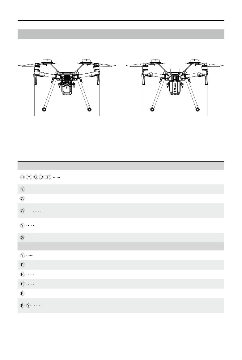
Flight Status Indicator
The aircraft features Front LEDs, a Rear LED, and Aircraft Status Indicators. The positions of these
LEDs are shown in the gure below:
Front LED Rear LED
The Front LEDs show the orientation of the aircraft. Front LEDs glow solid red when the aircraft is
turned on to indicate the front (or nose) of the aircraft. Front and rear LEDs can be turned off in the
DJI GO 4 app. The Aircraft Status Indicators communicate the system status of the ight controller.
Refer to the table below for more information about the Aircraft Status Indicators.
Aircraft Status Indicator Description
Normal
Red, yellow, green,
blue, and purple ashes
Turning On and Self Diagnostic Testing
×4 Four yellow ashes Warming Up
Slow green ashing P-mode with GPS*
×2 Two green ashes
Slow yellow ashing
P-mode with Forward and Downward
Vision Systems*
No GPS and Forward and Downward
Vision Systems
Fast green ashing Braking
Warning
Fast yellow ashing Remote Controller Signal Lost
Slow red ashing Low Battery Warning
Fast red ashing Critical Low Battery Warning
Red ashing IMU Error
— Solid Red Critical Error
Fast alternating red and yellow
ashing
Compass Calibration Required
* Slow green ashes indicate P-mode, and fast green ashes indicate S-mode.
Aircraft
Status
Indicator
2017 DJI All Rights Reserved.
©
16
Page 17
MATRICE 200 Series User Manual
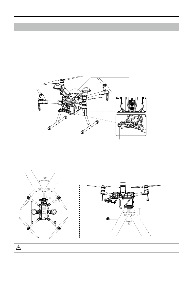
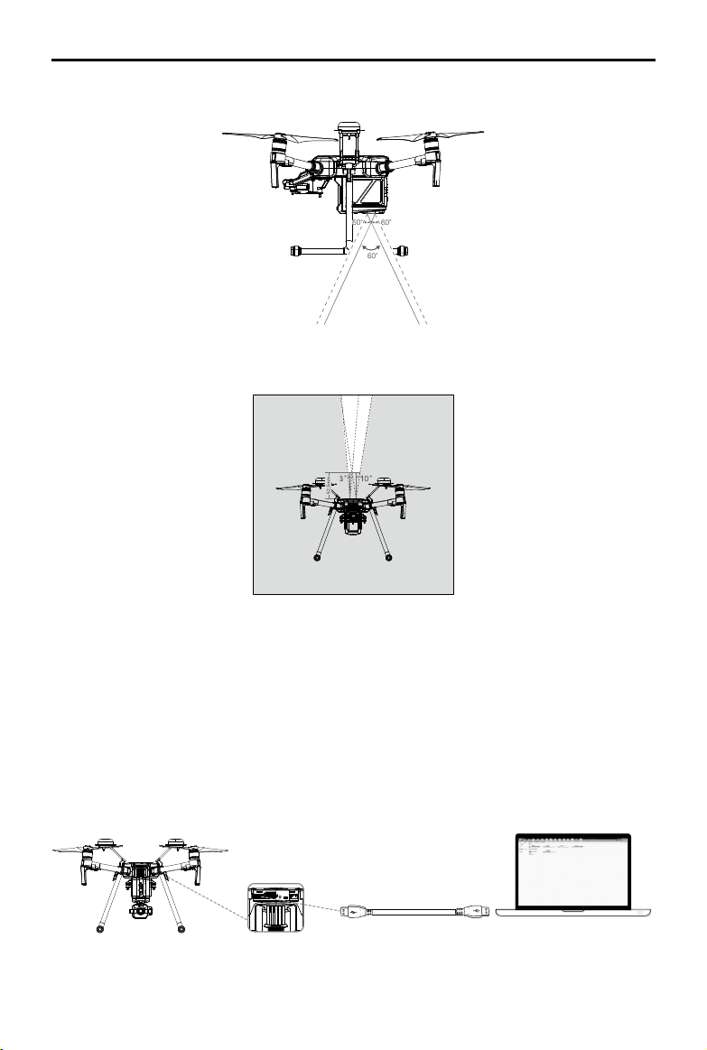
Vision System and Infrared Sensing System
The main components of the Vision System are located on the front and bottom of the aircraft, including [1] [3] stereo vision sensors and [2] two ultrasonic sensors. The Vision Sys tem uses ultrasound and image data to help the aircraft maintain its current position, enabling precision hovering
indoors or in environments where a GPS signal is not available. The Vision System constantly scans
for obstacles, allowing the aircraft to avoid them by going over, going around, or hovering.
The Infrared Sensing System consists [4] of two infrared modules on top of the aircraft. These scan
for obstacles on top side of the aircraft and is active in certain ight modes.
[4]
[3]
[2]
[1]
Detection Range
The detection range of the Vision System is depicted below. Note that the aircraft cannot sense
and avoid obstacles that are not within the detection range.
60cm
40cm
The aircraft cannot detect objects in low-light conditions. Please y with caution.
2017 DJI All Rights Reserved.
©
17
Page 18
MATRICE 200 Series User Manual
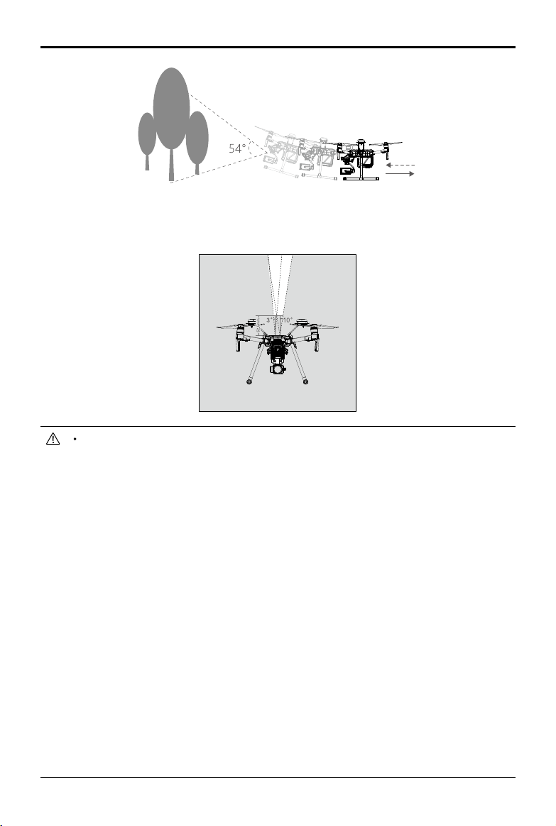
Ultrasonic sensor detection range is depicted below.
Infrared Sensing System detection range is depicted below.
Calibration
The Forward and Downward Vision System cameras are calibrated prior to delivery. However, these
cameras are vulnerable to impact and will require occasional calibration via DJI Assistant 2.
Calibration with the included Visual Calibration Plate.
1. Power on the Intelligent Flight Battery and toggle the USB Mode Switch left.
2. Connect the aircraft and the PC with a male to male USB cable.
3. Launch DJI Assistant 2 and log in with a DJI account.
4. Click M200SERIES and the calibration button.
2017 DJI All Rights Reserved.
©
18
Page 19
MATRICE 200 Series User Manual
5. Place the side of visual calibration plate with the dots facing the Forward Vision System, and
follow the instructions in the DJI Assistant 2 to complete calibration.
6. Place the aircraft straight, and ensure the dotted side of the visual calibration plate faces the
Downward Vision System. Follow the instructions in DJI Assistant 2 to complete calibration.
Calibrating with a Screen
Follow the steps below to calibrate the camera.
Point the aircraft toward the screen
1
2
Align the boxes
3
Pan and tilt the aircraft
DO NOT power off or unplug the USB cable after calibration. Wait for data calculation.
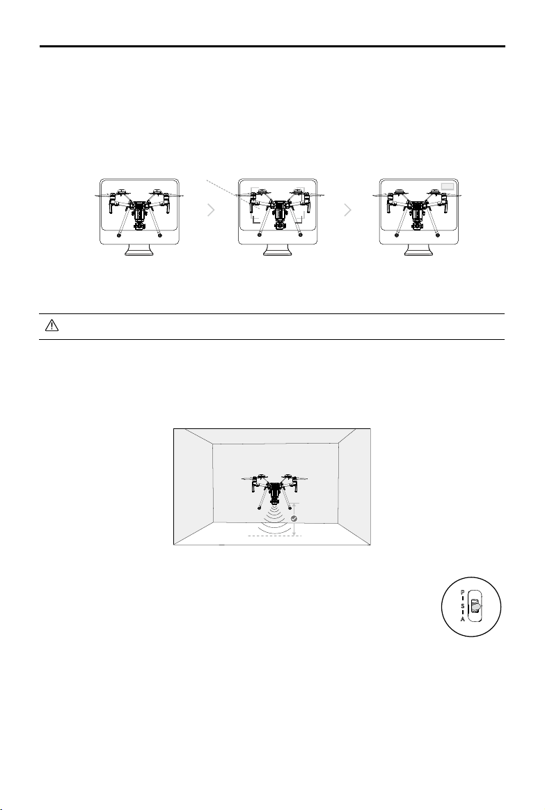
Using the Vision System
The Vision System is activated automatically when the aircraft is turned on. No further action is
required. The Vision System enables precision hovering indoors or in environments where GPS signal
isn't available.
Follow the steps below to use the Vision System:
1. Ensure the aircraft is in P-mode and place the aircraft on a at surface. Note
that the Vision System cannot work properly on surfaces without clear pattern
variations.
2. Turn on the aircraft. The aircraft will hover in place after takeoff. The aircraft
status indicators will flash green twice, which indicates the Vision System is
working. Gently push the left stick up to lift off and the aircraft will hover in place.
Assisted Braking from Obstacle Sensing
Powered by the Forward Vision System, the aircraft is able to actively brake when obstacles are
detected in front. Obstacle Sensing works best when lighting is adequate and the obstacle is
clearly textured. The aircraft must y at no more than 31 mph (50 kph) to allow for sufcient braking
distance.
2017 DJI All Rights Reserved.
©
19
Page 20
MATRICE 200 Series User Manual
Using Infrared Sensing System
The Infrared Sensing System can only be used to avoid large, diffuse, and reflective obstacles
(reectivity >10%). Please be mindful of blind spots (Grey) of the Infrared Sensing System.
The performance of your Vision System and Infrared Sensing System is affected by the surface
being own over. Ultrasonic sensors may not be able to accurately measure distances when
operating above sound-absorbing materials and the cameras may not function correctly in
suboptimal environments. The aircraft will switch from P-mode to A-mode automatically if neither
GPS nor Vision System and Infrared Sensing System are available. Operate the aircraft with
great caution in the following situations.
The Vision System will be disabled when:
a) Flying over monochrome surfaces (e.g. pure black, pure white, pure red, pure green).
b) Flying over highly reective surfaces.
c) Flying over water or transparent surfaces.
d) Flying over moving surfaces or objects.
e) Flying in an areas where the lighting changes frequently or drastically.
f) Flying over extremely dark (lux < 10) or bright (lux > 100,000) surfaces.
g) Flying over surfaces without clear patterns or texture.
h) Flying over surfaces with identical repeating patterns or textures (e.g. tiling).
i) Flying at high speeds of over 31 mph (50 kph) at 2 meters or over 11 mph (18 kph) at
1 meter.
The Ultrasonic sensors will be disabled when:
a) Flying over surfaces that can absorb sound waves (e.g. thick carpet).
b) Flying over inclined surfaces that will deect sound waves away from the aircraft.
The Infrared be disabled when:
a) Flying over obstacles with too small effective infrared reective surface.
b) DO NOT cover the protective glass of the infrared module. Keep it clean and undamaged.
2017 DJI All Rights Reserved.
©
20
Page 21
MATRICE 200 Series User Manual
Keep sensors clean at all times. Dirt or other debris may adversely affect their effectiveness.
Vision System is only effective when the aircraft is at altitudes of 0.3 to 10 meters.
The Vision System may not function properly when the aircraft is ying over water.
The Vision System may not be able to recognize pattern on the ground in low light
conditions (less than 100 lux).
Do not use other ultrasonic devices with frequency of 40 KHz when Vision System is in
operation.
Keep away from animals while operating the aircraft, as the ultrasonic sensors emit highfrequency sounds which may disturb them.
2017 DJI All Rights Reserved.
©
21
Page 22
MATRICE 200 Series User Manual
Return-to-Home (RTH)
The Return-to-Home (RTH) function brings the aircraft back to the last recorded Home Point. There
are three types of RTH: Smart RTH, Low Battery RTH, and Failsafe RTH. This section describes
these three RTH types in detail.
GPS
If a strong GPS signal was acquired before takeoff, the Home Point is
the location from which the aircraft launched. The GPS signal strength is
Home Point
indicated by the GPS icon . Less than 4 bars is considered a weak
GPS signal. The aircraft status indicator will blink rapidly when the home
point is recorded.
The aircraft can sense and avoid obstacles when the Forward Vision System is enabled and
lighting conditions are sufcient. The aircraft will automatically ascend to avoid obstacles and
descend slowly as it returns to the home point. To ensure the aircraft returns home while facing
forward, it cannot rotate or y left and right during RTH while the Forward Vision System is
enabled.
Smart RTH
Use the RTH button on the remote controller or tap the RTH button in the DJI GO 4 app and
follow the on-screen instructions when GPS is available to initiate Smart RTH. The aircraft will
then automatically return to the last recorded Home Point. Use the remote controller to control the
aircraft’s speed or altitude to avoid a collision during the Smart RTH process. As the aircraft returns,
it will use the primary camera to identify obstacles as far as 300m in front, allowing it to plan a safe
route home. Press and hold the Smart RTH button once to start the process, and press the Smart
RTH button again to terminate the procedure and regain full control of the aircraft.
Description
Low Battery RTH (Can be turned off in DJI GO 4 app)
The low battery level failsafe is triggered when the DJI Intelligent Flight Battery is depleted to a point
that may affect the safe return of the aircraft. Users are advised to return home or land the aircraft
immediately when prompted. The DJI GO 4 app will display a notice when a low battery warning
is triggered. The aircraft will automatically return to the Home Point if no action is taken after a tensecond countdown. The user can cancel the RTH procedure by pressing the RTH button on the
remote controller. The thresholds for these warnings are automatically determined based on the
aircraft’s current altitude and distance from the Home Point.
The aircraft will land automatically if the current battery level can only support the aircraft long
enough to descend from its current altitude. The user can still use the remote controller to alter the
aircraft’s orientation during the landing process.
The Battery Level Indicator is displayed in the DJI GO 4 app, and is described below:
Sufcient battery
level (Green)
H
Power required
to return home
Battery level Indicator
Remaining ight time
12:29
2017 DJI All Rights Reserved.
©
22
Critical Low battery level
warning (Red)
Low battery
level warning (Yellow)
Page 23
MATRICE 200 Series User Manual
Battery
Level
Warning
Low battery
level
warning
Critical Low
battery level
warning
Estimated
remaining
ight time
When the Critical Low battery level warning is triggered and the aircraft begins to land
automatically, push the left stick upward to make the aircraft hover at its current altitude,
giving you an opportunity to navigate to a more appropriate landing location.
The colored zones and markers on the battery level indicator bar reect the estimated
remaining ight time. They are automatically adjusted according to the aircraft’s current
location and status.
Remark
Battery power
is low. Land
the aircraft.
The aircraft
must land
immediately.
Estimated
remaining time is
based on current
battery level.
Aircraft Status
Indicator
Aircraft status
indicator blinks
RED slowly.
Aircraft status
indicator blinks
RED quickly.
N/A N/A N/A
DJI GO 4 App
Tap “Go-home” to have the
aircraft return to the Home
point and land automatically,
or “Cancel” to resume normal
flight. If no action is taken,
the aircraft will automatically
go home and land after 10
seconds. Remote controller
will sound an alarm.
The DJI GO 4 app display
will ash red and the aircraft
will start to descend. The
remote controller will sound
an alarm.
Fly the aircraft
back and land
it as soon as
possible, then
stop the motors
and replace the
battery.
Allow the aircraft
to descend
and land
automatically.
Flight
Instructions
Failsafe RTH
If the Home Point was successfully recorded and the compass is functioning normally, Failsafe RTH
will be automatically activated if the remote controller signal is lost for more than three seconds.
The aircraft will plan its return route and retrace its original ight route home. The user may cancel
Failsafe RTH to regain control when connection is reestablished.
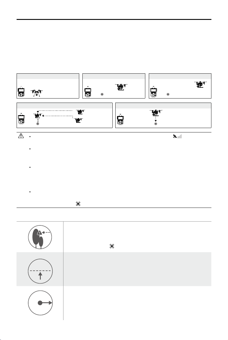
RTH Procedure
1. Home Point is recorded automatically.
2. RTH procedure is triggered i.e., Smart RTH, Low-Battery RTH, and Failsafe RTH.
3. Home Point is conrmed and the aircraft adjusts its orientation.
4. a. The aircraft will ascend to the pre-set RTH attitude and then y to the Home Point when the
aircraft is further than 20 m from the Home Point.
b. When the aircraft is between 3 m and 20 m from the Home Point, it will return to the Home Point at
the current altitude with the RTH at Current Altitude option enabled (the default setting in DJI GO 4)
if ying at or above 2.5 m. It will ascend to 2.5 m then return to home if ying lower than 2.5 m.
2017 DJI All Rights Reserved.
©
23
Page 24
MATRICE 200 Series User Manual
20 m
H
RTH Altitude
Note: If RTH at Current Altitude is disabled in DJI GO 4, the aircraft will land automatically when
the aircraft is between 3 m and 20 m from the Home Point.
c. The aircraft will land automatically if RTH is triggered and the aircraft is less than 3 m from the
home point.
5. The aircraft will hover 0.7 m above ground and wait for conrmation from the user. The aircraft
will land and stop its motors after user conrmation.
Use the Failsafe RTH for example:
1. Record Home Point 2. Remote Control Signal Lost
3. Signal Lost for Extended Time
4. RTH (Adjustable Altitude)
Height over HP>Failsafe Altitude
Elevate to Failsafe Altitude
Failsafe Altitude
Height over HP<=Failsafe Altitude
5. Landing (After User Conrmation)
Hovering at 0.7 meters above the Home Point
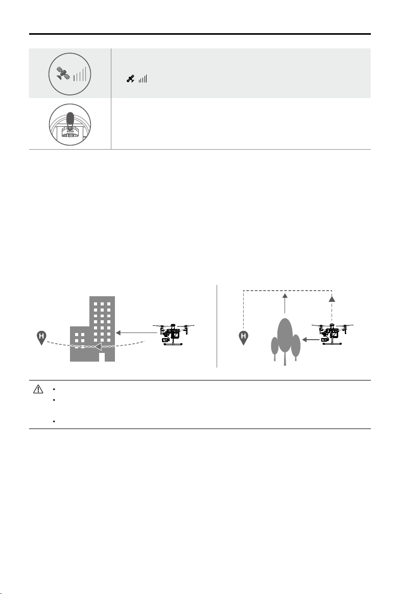
Aircraft cannot return to the Home Point when GPS signal is weak ( [ ] Less than 4
bars is considered a weak GPS signal) or unavailable.
User cannot control the aircraft while the aircraft is ascending to 65 feet (20 meters) from
the current altitude. However, users can press the RTH button once to exit ascending and
regain control.
The aircraft will automatically descend and land if RTH is triggered when the aircraft ies
within a 65 feet (20 meters) radius of the Home Point. The aircraft will stop ascending and
will return to the Home Point if the aircraft reaches 65 feet (20 meters) in altitude or beyond
during Failsafe.
The aircraft cannot avoid obstacles during Failsafe RTH if the Forward Vision System is
disabled. It is important to set a suitable RTH Altitude before each ight. Launch DJI GO 4,
enter camera and tap to set Failsafe Altitude.
Failsafe Safety Notices
The aircraft cannot avoid obstacles during Failsafe RTH when the
Forward Vision System is disabled. Therefore, it is important to set a
suitable Failsafe altitude before each ight. Launch the DJI GO 4 app,
enter Camera and tap to set the Failsafe Altitude.
If the aircraft is ying under 65 feet (20 meters) and Failsafe (including
20 m
Smart RTH, Lower Battery RTH) is triggered, the aircraft will first
automatically ascend to 65 feet (20 meters) from the current altitude. You
can only cancel the ascending by exiting the Failsafe.
20 m
H
2017 DJI All Rights Reserved.
©
24
The aircraft automatically descends and lands if RTH is triggered when
the aircraft ies within a 65 foot (20 meter) radius of the Home Point. The
aircraft will stop ascending and immediately return to the Home Point if
you move the left stick when the aircraft is ying at an altitude of 65 feet (20
meters) or higher and Failsafe is triggered.
Page 25
MATRICE 200 Series User Manual
The aircraft cannot return to the Home Point when GPS signal is weak
( [ ] displaying less than four bars) or is unavailable.
If you move the left stick when the aircraft is flying above 65 feet (20
meters) but below the pre-set Failsafe RTH altitude, the aircraft will stop
ascending and immediately return to the Home Point.
Obstacle Avoidance During RTH
The aircraft can sense and actively attempt to avoid obstacles during RTH, provided that lighting
conditions are adequate for the Forward Vision System. Upon detecting an obstacle, the aircraft will
act as follows:
1. The aircraft will use the primary camera to identify obstacles as far away as 984 feet (300 meters)
in front, allowing it to plan a safe route home.
2. The aircraft decelerates when an obstacle is sensed at 49 feet (15 meters) ahead.
3. The aircraft stops and hovers then starts ascending vertically to avoid the obstacle. Eventually,
the aircraft will stop climbing when it is at least 16 feet (5 meters) above the detected obstacle.
4. RTH procedure resumes. The aircraft will continue ying to the Home Point at the current altitude.
5 meters
300 meters
15 meters
Obstacle Sensing is disabled during RTH descent. Proceed with care.
To ensure the aircraft returns home forwards, it cannot rotate during RTH while the For-
ward Vision System is enabled.
The aircraft cannot avoid obstacles beside or behind it.
Landing Protection Function
Landing Protection will activate during auto-landing.
1. Landing Protection determines whether the ground is suitable for landing. If so, the aircraft will
land smoothly.
2. If Landing Protection determines that the ground is not suitable for landing, the aircraft will hover and
wait for pilot conrmation. The aircraft will hover if it detects the ground is not appropriate for landing
even with a critically low battery warning. Only when the battery level decreases to 0% will the aircraft
land. Users retain control of aircraft ight orientation.
3. If Landing Protection is inactive, the DJI GO 4 app will display a landing prompt when the aircraft
descends below 0.7 meters. Tap to conrm or pull down the control stick for 2 seconds to land when
the environment is appropriate for landing.
2017 DJI All Rights Reserved.
©
25
Page 26

MATRICE 200 Series User Manual
ISO
SHUTTER
EV
SD TIME
WB
Landing Protection will not be active in the following circumstances:
When the user is controlling the pitch/roll/throttle sticks (Landing Protection will re-activate
when the control sticks are not in use)
When the positioning system is not fully functional (e.g. drift position error)
When the downward vision system needs re-calibration
When light conditions are not sufcient for the downward vision system
If an obstacle is within one meter of the aircraft, the aircraft will descend to 0.7m above the
ground and hover. The aircraft will land after user conrmation.
Intelligent Flight Modes
TapFly
Introduction
With the TapFly feature, users can now tap on the mobile device screen to y in the designated direction
without using the remote controller. The aircraft will automatically avoid obstacles it sees or brake and hover
in front of them, provided that there is sufcient light between (< 300 lux) and (> 10,000 lux).
Using TapFly
Ensure that the Intelligent Flight Battery is fully charged and the aircraft is in P-mode. Follow the steps
below to use TapFly:
1. Take off and ensure the aircraft is hovering at least 6 ft (2 m) above ground.
2. Launch DJI GO 4 and tap , Select TapFly, then follow the prompts.
In Flight (GPS)
200 0.3F5.61/200 20:12
2017 DJI All Rights Reserved.
©
26
30m
P-GPS
H
10.0
km/h
VS 2.0
5000K
2 meters
4.07V
12
09:29
Custom
4KP30
mD
m/s
VPS 2.0mH.S 10.0
74%
70%
4.07V
AF/MF
AE
Page 27
MATRICE 200 Series User Manual
ISO
SHUTTER
EV
SD TIME
WB
ISO
SHUTTER
EV
SD TIME
WB
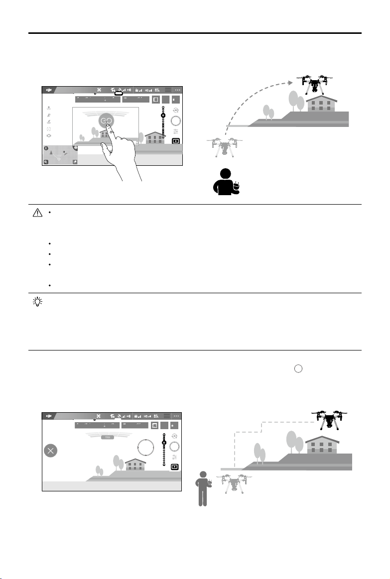
3. Tap once on the target and wait for the “GO” icon to appear. Tap the “GO” icon to conrm the
selection and the aircraft will automatically y toward the target.
4.07V
In Flight (GPS)
200 0.3F5.61/200 20:12
12
P-GPS
09:29
Custom
4KP30
5000K
74%
70%
4.07V
AF/MF
AE
30m
H
10.0
mD
m/s
VS 2.0
VS 2.0M/S
VPS 2.0mH.S 10.0
km/h
FPV
DO NOT y the aircraft over people, animals, small or ne objects (e.g. tree branches and power
lines) or transparent objects (e.g. glass or water). TapFly may not work properly when the aircraft
is ying over water or snow covered areas.
Watch for obstacles in the ight path and steer clear of them.
There may be deviations between expected and actual ight paths selected in TapFly.
The selectable range for target direction is limited. You cannot make a selection in Direction close
to the upper or lower edge of the screen.
Be extra cautious when ying in too dark (< 300 lux) or too bright (>10,000 lux) environments.
Enable control stick control of the gimbal inside DJI GO 4 to control gimbal orientation using the
remote controller. When using the control sticks, the gimbal will automatically switch to Free mode.
In this situation, the control stick used to control pitch on the aircraft now controls gimbal pitch,
and the control stick used to control aircraft roll now controls gimbal pan. The left dial now controls
ight speed.
After conrming your TapFly selection, the aircraft will y in the direction marked by the icon. Note that you
can still use the control stick to control the movement of the aircraft during the ight.
4.07V
In Flight (GPS)
200 0.3F5.61/200 20:12
12
P-GPS
09:29
Custom
5000K
4KP30
74%
70%
4.07V
AF/MF
AE
H
10.0
30m
mD
m/s
VS 2.0
VPS 2.0mH.S 10.0
2017 DJI All Rights Reserved.
©
27
km/h
Page 28

MATRICE 200 Series User Manual
The aircraft automatically adjusts its speed when it senses an obstacle in front, or if it ies too close
to the ground. The DJI GO 4 app will show a prompt if the aircraft ies over an obstacle or to the
left or right of the obstacle. However, this feature should not be relied upon for navigation between
obstacles. Failsafe procedures will override TapFly. If the GPS signal weakens, the aircraft will exit
autonomous ight and return to home.
30M
30M
Exit TapFly
Use the following methods to exit TapFly:
1. Tap the “ ” icon on the screen.
2. Pull back the pitch stick on the remote controller and hold for three seconds or more..
3. Press the Intelligent Flight Pause button on the remote controller.
OR OR
The aircraft will stop and hover after exiting from TapFly. Tap a new target direction to continue ying or
begin manual ight.
Pause button
ActiveTrack
ActiveTrack allows you to mark and track a moving object on your mobile device's screen. The
aircraft will automatically avoid obstacles in its ight path. No external tracking device is required.
The aircraft will automatically identify and trace bicycles and other vehicles, people, and animals,
using different tracking strategies for each.
Using ActiveTrack
Ensure the Intelligent Flight Battery is fully charged and the aircraft is in P Mode. Follow the steps
below to use ActiveTrack:
1. Take off and hover at least 6 feet (2 meters) above the ground.
2 meters
2017 DJI All Rights Reserved.
©
28
Page 29

MATRICE 200 Series User Manual
ISO
SHUTTER
EV
SD TIME
WB
ISO
SHUTTER
EV
SD TIME
WB
2. In DJI GO 4, tap to bring up the ight modes and select ActiveTrack.
4.07V
In Flight (GPS)
200 0.3F5.61/200 20:12
30m
P-GPS
km/h
12
09:29
Custom
4KP30
5000K
H
10.0
mD
m/s
VPS 2.0mH.S 10.0
VS 2.0
74%
70%
4.07V
AF/MF
AE
3. Tap on the subject you want to track, then tap to confirm your selection. If the subject is not
automatically recognized, drag a box around it. The box will turn green when tracking is in
progress. If the box turns red, the object was not identied and you should try again.
4.07V
In Flight (GPS)
200 0.3F5.61/200 20:12
智能跟随
30m
km/h
12
P-GPS
09:29
Custom
4KP30
5000K
H
10.0
mD
m/s
VS 2.0
74%
70%
4.07V
AF/MF
AE
VPS 2.0mH.S 10.0
ActiveTrack includes the following functions:
Trace Prole
The aircraft tracks the subject at a x distance.
Use the roll stick on the remote controller or the
slider in DJI GO 4 to circle the subject.
The aircraft tracks the subject at fix angle and
distance from the side. Use the roll stick on the
remote control to circle the subject. The aircraft
will not be able to avoid obstacles while in Prole
Mode. Use this mode in open areas.
2017 DJI All Rights Reserved.
©
29
Page 30

MATRICE 200 Series User Manual
DO NOT select an area with people, animals, small or ne objects (e.g. trees and power lines),
or transparent objects (e.g. glass or water).
Stay clear of obstacles near the ight path, particularly when the aircraft is ying backward.
Be extra vigilant when using ActiveTrack in any of the following situations:
a) The tracked subject is not moving on a level plane.
b) The tracked subject changes shape drastically while moving.
c) The tracked subject could be blocked or out of sight for a long time.
d) The tracked subject is moving on a snowy surface.
e) Available light is too low (< 300 lux) or too high (> 10,000 lux).
f) The tracked subject has a similar color or pattern as its surrounding environment.
You must follow local privacy laws and regulations when using ActiveTrack.
Aircraft will not be able to avoid obstacles while in Prole or Spotlight Mode. Use these modes
in open areas.
Exiting ActiveTrack
Use the following methods to exit ActiveTrack:
1. Tap the “ ” button on the screen.
2. Press the Intelligent Flight Pause button on the remote controller.
After exiting ActiveTrack, the aircraft will hover in place, at which point you may choose to fly
manually, track another subject, or return to home.
OR
Tripod Mode
Tap the icon in DJI GO 4 to enable Tripod Mode. Tripod Mode reduces the aircraft’s maximum
speed (this can be adjusted in DJI GO 4 app), and the control stick sensitivity of the remote
controller is dulled to give you the precision you need for accurate framing. Tripod Mode allow the
aircraft to be used as a rocker arm or slide rail, shooting smoother, more stable footage.
Only use Tripod mode when GPS signal is strong or in ideal light conditions for the Vision
System. If GPS signal is lost and the Vision System does not function, it will automatically
switch to ATTI mode. In this case, ight speed will increase and the aircraft will not hover in
place. Use Tripod mode carefully.
Spotlight Pro
Spotlight Pro is a powerful new tracking mode that allows a single pilot to capture complex,
dramatic images. The gimbal will automatically adjust to keep the camera pointing at the subject.
Lock onto a subject in Spotlight Pro mode and the gimbal will capture the locked subject regardless
of the directions that the aircraft ies.
Quick Mode: Use your nger to draw a square around the object in to begin tracking.
Composition Mode: Use your nger to draw a square. When the subject enters the square, press
the C2 button to begin tracking. Press the C2 button again to stop tracking.
In Free mode, you can control the aircraft’s heading independently of the camera.
In Follow mode, the aircraft heading will be the same as that of the camera.
2017 DJI All Rights Reserved.
©
30
Page 31

MATRICE 200 Series User Manual
ISO
SHUTTER
EV
SD TIME
WB
4.07V
12
In Flight (GPS)
Aircraft Head
Follow
Settings
Compisition
You can drag on a subject in DJI GO 4 or move the gimbal control sticks to change the
Free
Quick Compisition
Aircraft Head
Follow
Free
Settings
Quick Compisition
Compisition
P-GPS
09:29
30m
Custom
4KP30
5000K
H
10.0
mD
m/s
km/h
VS 2.0
200 0.3F5.61/200 20:12
74%
70%
4.07V
AF/MF
AE
VPS 2.0mH.S 10.0
subject's position in the shot.
Spotlight Pro can be used in S-mode, A-mode, TapFly and Tripod mode.
Flight Recorder
Flight data is automatically recorded to the internal storage of the aircraft. This includes flight
telemetry, aircraft status information, and other parameters. To access this data, connect the
aircraft to a PC via the USB port and launch DJI Assistant 2.
Attaching and Detaching the Propellers
Attaching the Propellers
Refer to "Mounting the Propellers" for details.
Detaching the Propellers
Press the propeller down onto the mounting plate and rotate it in the unlock direction.
Propeller blades are sharp; please handle with care.
Only use DJI approved propellers. DO NOT mix propeller types.
Stay clear of spinning motors. DO NOT touch the propellers when they are spinning.
Ensure to check that the propellers and motors are installed rmly and correctly before
each ight.
Ensure that all propellers are in good condition before each ight. DO NOT use aged,
chipped, or broken propellers.
To avoid injury, stand clear of and DO NOT touch propellers or motors when they are
spinning.
Please use original DJI propellers for a better and safer ight experience.
DJI Intelligent Flight Battery
Matrice 210/210 RTK provides two types of Intelligent Flight Battery, which have the same functions.
The main difference between TB50-M200 and TB55 is that the TB55 is a high-capacity battery. This
manual uses the TB50-M200 as an example to demonstrate setup and usage.
The TB50-M200 Intelligent Flight Battery has a capacity of 4280 mAh, a voltage of 22.8 V, and a
smart charge/discharge functionality. It should only be charged using appropriate DJI approved
chargers.
2017 DJI All Rights Reserved.
©
31
Page 32
MATRICE 200 Series User Manual
DJI Intelligent Flight Battery Functions
1. Battery Level Display: The LED indicators display the current battery level.
2. Auto-Discharging: To prevent swelling, the battery automatically discharges to below 70% of
the total power when it is idle (press the power button to check that the battery level will cause
the battery to exit idle state) for more than 10 days to prevent swelling. It takes around 3 days to
discharge the battery to 65%.It is normal to feel moderate heat emitting from the battery during
the discharge process. Discharge thresholds can be set in DJI GO 4.
3. Balanced Charging: Automatically balances the voltage of each battery cell when charging.
4. Overcharge Protection: Charging automatically stops when the battery is fully charged.
5. Temperature Detection: The battery will only charge when the temperature is between 5 °C (41°F)
and 45°C (113°F).
6. Over Current Protection: The battery stops charging when a high amperage (more than 10 A) is
detected.
7. Over Discharge Protection: Over-discharging can seriously damage the battery. Current output will
be cut off when the battery cell is discharged to 2.8 V when not in ight mode. For extended ight
times, over-charging protection is disabled as batteries discharge during ight. In this instance, a
battery voltage below 2 V may cause a safety hazard such as a re when charged. To prevent this,
the battery will not be able to charge if the voltage of a single battery cell is below 2 V. Avoid using
any batteries matching this description and avoid serious over-discharging to prevent permanent
battery damage.
8. Short Circuit Protection: Automatically cuts the power supply when a short circuit is detected.
9. Battery Cell Damage Protection: DJI GO 4 displays a warning message when a damaged battery
cell is detected.
10. Sleep Mode: Sleep mode is entered to save power when the aircraft is not ying.
11. Communication: Information pertaining to the battery’s voltage, capacity, current, etc. is
transmitted to the aircraft’s main controller.
12. Pairing Batteries: Powered by two batteries (with battery cells connected in parallel), the aircraft
requires the two batteries to have similar properties, e.g. internal resistance. Pairing batteries in
the beginning is recommended. Pairing can be done using DJI GO 4. DJI GO 4 will also prompt
you when batteries that are not paired are not in use. The Intelligent Flight Battery Charging Hub
will charge paired batteries simultaneously. Stickers are provided for marking paired batteries.
13. Heating: Batteries are able to work even in cold weather, ensuring a safe ight. Refer to "Using
the Battery" section for details.
14. Waterproof and Dustproof: The vehicle’s new airframe design improves the Ingress Protection
Rating to IP43 in accordance with the global IEC 60529 standards.
Refer to the
take full responsibility for all operations and usage.
Disclaimer
and
Intelligent Flight Battery Safety Guidelines
before use. Users
Charging the Intelligent Flight Battery
The Intelligent Flight Battery Charging Hub is designed for use with the Battery Charger. It charges
up to four Intelligent Flight Batteries simultaneously. The battery pair with more stored power will be
charged rst. The Charging Hub will intelligently charge batteries in sequence according to battery
power levels from high to low, if batteries are not paired. Pairing can be carried out using the DJI
GO 4 app. The Micro USB port is used for rmware updates.
2017 DJI All Rights Reserved.
©
32
Page 33
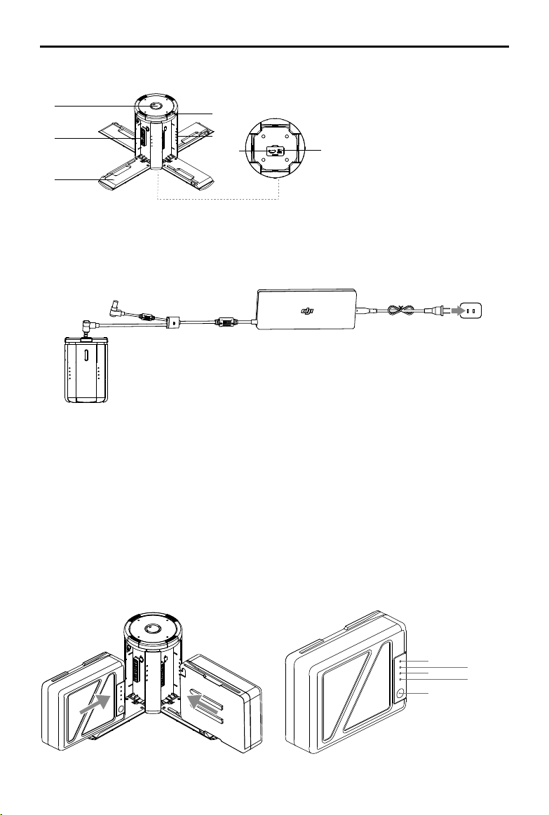
Overview
MATRICE 200 Series User Manual
[1]
[2]
[3]
[6]
[5]
[4]
[7]
[1] Power Port
[2] Charging Port
[3] Charging Port Cover
[4] Battery Charging Level Indicators
[5] Cover/Battery Release Button
[8]
[6] Status LEDs
[7] Firmware Update Port (Micro USB)
[8] Buzzer Switch
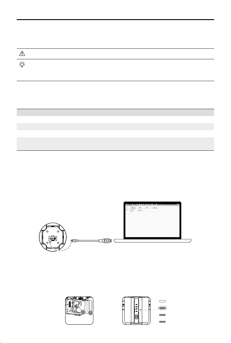
Connecting to a Power Source
Connect the standard Battery Charger to a power outlet (100-240 V, 50/60 Hz), then uncover the
rubber cover on the power port to connect the Charging Hub to the Battery Charger*.
Power OutletChargerCharging Hub
* It will take approximately 1.5 hours to fully charge the TB50-M200 Intelligent Flight Battery, and 3 hours for the
remote controller. It will take a longer time to charge the Intelligent Flight Battery and remote controller together.
Connecting Batteries
Press the release button and open the corresponding charging port cover. Insert the Intelligent
Flight Battery into the charging port to begin charging. The battery pair with more stored power
will be charged rst. The Charging Hub will intelligently charge batteries in sequence according to
battery power levels from high to low, if batteries are not paired. Pairing can be carried out using the
DJI GO 4 app. Refer to the "Status LED Description” section for more information about Status LED
blinking patterns. The buzzer will begin beeping when charging is complete. Refer to the “Buzzer
Beeping Description” for more information about buzzer beeping patterns.
LED1
LED3
Battery Level Button
2017 DJI All Rights Reserved.
©
LED2
LED4
33
Page 34
MATRICE 200 Series User Manual
Always align the grooves on the Intelligent Flight Battery with the battery slot tracks.
Press the release button to detach batteries after charging is complete.
DO NOT leave metal terminals exposed to open air when not in use.
Status LED Descriptions
Status LED (Charging Hub) Description
Blinks Green Charging
— Solid Green Fully charged
Blinks Red Battery Charger Error. Retry with an ofcial battery charger.
— Solid Red Intelligent Flight Battery error
Blinks Yellow
Battery temperature too high/low. Temperature must be within
operating range (5°-40℃)
— Solid Yellow Ready to charge
Alternating Green Blinks Intelligent Flight Battery not detected
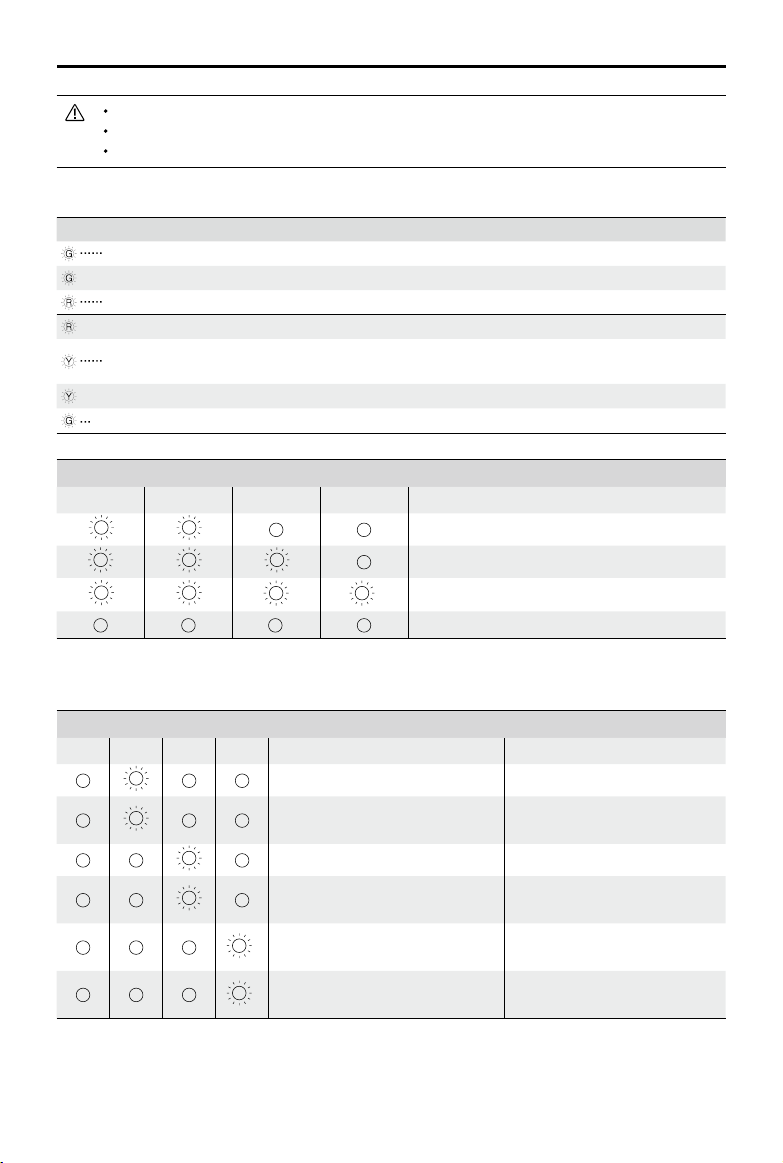
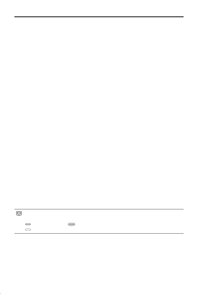
Battery Level Indicators while Charging (Battery)
LED1 LED2 LED3 LED4 Battery Level
0%~50%
50%~75%
Charging Protection LED Display
75%~100%
Fully Charged
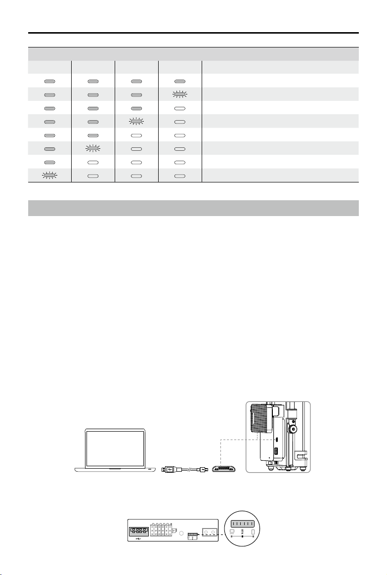
The table below shows battery protection mechanisms and corresponding LED patterns.
Battery Level Indicators for Battery Protection
LED1 LED2 LED3 LED4 Blinking Pattern Battery Protection Item
LED2 blinks twice per second Over current detected
LED2 blinks three times per
second
Short circuit detected
LED3 blinks twice per second Over charge detected
LED3 blinks three times per
second
LED4 blinks twice per second
LED4 blinks three times per
second
Over-voltage charger detected
Charging temperature is too
low (<0°C)
Charging temperature is too
high (>40°C)
After any of the above mentioned protection issues are resolved, press the button to turn off the
Battery Level Indicator. Unplug the Intelligent Flight Battery from the charger and plug it back in to
2017 DJI All Rights Reserved.
©
34
Page 35
MATRICE 200 Series User Manual
resume charging. Note that you do not need to unplug and plug the charger in the event of a room
temperature error, the charger will resume charging when the temperature falls within the normal
range.
DJI does not take any responsibility for damage caused by third-party chargers.
How to discharge the Intelligent Flight Battery before transporting the batteries for a trip:
Fly the aircraft outdoors until there is low battery power left, or until the battery can no
longer be turned on.
Buzzer Beeping Description
Toggle the buzzer switch to turn on/off the warning sound.
Descriptions Beeping Pattern
Toggle the buzzer switch to turn it on Quick beeping
Connect to the Battery Charger Quick beeping
A battery pair is fully charged Quick beeping
Four Intelligent Flight Batteries are fully charged
Updating the Firmware
Alternating between two short and one
long beep, lasting for about 1 hour
DJI will release rmware updates when available. Refer to the ofcial DJI website and follow the
instructions below to update the rmware.
1. Download the latest rmware update program from the ofcial DJI website.
(http://www.dji.com/matrice-200-series/info#downloads)
2. Turn on the Charging Hub, then connect it to a computer using a Micro USB cable.
3. Run the rmware update program. Press the update button and wait for the process to nish.
4. The Charging Hub will automatically restart when the update has been successfully completed.
5. Repeat this process if the rmware update fails for any reason.
Using the Battery
A
B
2017 DJI All Rights Reserved.
©
35
Page 36
MATRICE 200 Series User Manual
Turning ON/OFF
Turning On:
Press the Power button once, then press again and hold for two seconds to power on.
The Power LED will turn red and the Battery Level Indicators will display the current
battery level.
Turning Off:
Heating the Battery
Manual Heating:
Press the Power button once, then press again and hold for two seconds to power off.
Make sure the battery is powered off. Press and hold the Power button for three
seconds to initiate battery warm up manually.
The battery will warm up if the temperature is below 59℉ (15℃). As it warms, LEDs 1 & 2 and
LEDs 3 & 4 will blink alternately. The battery will stop warming when it reaches 68℉ (20℃). The
temperature of the battery will be remain between 59-68℉ (15-20℃) when alternating LED 1 and
LED 4 blinking indicates that it is above 59℉ (15℃). This will last for approximately 30 minutes,
powering off automatically.
Auto Heating:
Insert the batteries into the aircraft and power it on. When the temperature of the
battery is below 59℉ (15℃), it will warm up automatically. Check the LEDs for the current power
level.
Low Temperature Notice:
1. The performance of the intelligent Flight Battery is significantly reduced when flying in low
temperature environments (temperatures below 5℃). Ensure that the battery is fully charged and
the cell voltage is at 4.35 V before each ight.
2. End the ight as soon as DJI GO 4 displays the “Low Battery Level Warning” in low temperature
environments. You will still be able to control the aircraft’s movement when this warning is
triggered.
3. In extremely cold weather, the battery temperature may not be high enough even after warming
up. In these cases, insulate the battery as required.
4. To ensure optimal performance of the battery, keep the battery temperature above 15℃.
5. Battery insulation paste is available for you to use.
Checking Battery Levels
Battery Level Indicators display how much power remains. When the battery is turned off, press the
Power button once and the Battery Level Indicators LEDs will display the current battery level. See
below for details.
The Battery Level Indicators will also show the current battery level during discharging. The
indicators are dened below.
: LED is on.
: LED is ashing.
: LED is off.
2017 DJI All Rights Reserved.
©
36
Page 37
MATRICE 200 Series User Manual
Battery Level
LED1 LED2 LED3 LED4 Battery Level
88%~100%
75%~88%
63%~75%
50%~63%
38%~50%
25%~38%
13%~25%
0%~13%
D-RTK and Datalink Pro
Introduction
For the M200 series, you can only activate D-RTK and Datalink Pro with the M210 RTK. Be sure to
activate both with DJI Assistant 2 before rst time use.
Using dual antennas, D-RTK provides more accurate heading data than a traditional single antenna
system, and it can withstand magnetic interference from metal structures. Depending on the region
of purchase, the D-RTK uses either GPS and BeiDou or GPS and GLONASS to perform at the
highest standards. The Datalink Pro is used to transmit the real-time data wirelessly.
Both D-RTK and Datalink Pro are composed with the air system and ground system. It is
recommended to use them in an open environment free from radio interference. Ensure the
antennas are unobstructed when in use. This manual uses the Datalink Pro 900 as an example.
Please refer to the D-RTK and Datalink Pro user guides for more details.
Activating D-RTK and Datalink Pro
1. Download DJI Assistant 2 from www.dji.com and install it on your computer.
2. Connect the D-RTK and Datalink Pro Ground Systems to the computer one by one with DJI
Assistant 2 launched for activation.
3. Connect the aircraft to the computer and toggle the USB Mode Switch to the RTK position to
activate the D-RTK air system.
2017 DJI All Rights Reserved.
©
37
Page 38

MATRICE 200 Series User Manual
4. Connect the Datalink Pro to the computer for activation.
Micro USB
Using the D-RTK
Use the D-RTK in an open environment free from radio interference and follow the procedures
below:
1. Power on the Ground System, and wait for the Working Status LED to turn solid green.
2. Power on the Air System, and wait for the aircraft Flight Status LED blinks green and blue
alternately.
Ensure that the D-RTK Ground System is powered on rst. DO NOT power on the aircraft
before the D-RTK Ground System’s Working Status LED is solid green.
Set the Flight Mode Switch to P mode or F mode.
Updating the Ground System’s Position
Each time it is used, the Ground System automatically detects the offset distance from its previous
position. If the offset distance is > 50 meters, the Ground System will update the new position
coordinates automatically. If the position has changed but the Ground System does not update
automatically, you will need to update manually. Press the Update button and hold for ve seconds
until the Ground System recalculates the position coordinates. The DJI GO 4 app will prompt you
once the Ground System’s position has been updated successfully.
DO NOT move the Ground System during positioning.
The Ground System’s position coordinates can be set in DJI Assistant 2.
DJI AirSense
Manned aircraft with an ADS-B transceiver will actively broadcast flight information including
location, flight path, speed, and altitude. DJI AirSense receives this by ADS-B transceivers via
an on-board receiver or internet connection. UAVs installed DJI AirSense can obtain the position,
orientation and velocity information from the manned airplane built-in ADS-B transmitter (1090 ES
and UAT standard supported), calculate the collision risk level real time and send the warning to
user. The system will analyze the potential risk of collision by comparing the location of a manned
aircraft, sending timely warnings to pilots via the DJI GO or DJI GO 4 app.
2017 DJI All Rights Reserved.
©
38
Page 39
MATRICE 200 Series User Manual
DJI AirSense provides users with information about nearby manned aircraft to ensure ight safety.
The system doesn’t actively control the drone to avoid incoming aircraft. Always y your aircraft
within a visual line of sight and be cautious at all times. Lower your altitude when you receive
warnings. Please be aware that DJI AirSense has the following limitations:
1. It can only receive messages sent by manned aircraft installed with an ADS-B out device and in
accordance with 1090ES (RTCA DO-260) or UAT (RTCA Do-282) standards. DJI devices will not
receive related broadcast messages or send out warnings for manned aircraft without ADS-B
outs or with malfunctioning ADS-B outs.
2. If there is an obstacle or steel structure between civil and DJI aircraft, the system won’t be able
to receive ADS-B messages sent by manned aircraft or send out warnings. Keenly observe your
surroundings and y with caution.
3. Warnings may be sent with delay when the DJI AirSense is interfered by the surrounding. Keenly
observe your surroundings and y with caution.
4. Warnings are not sent when a DJI aircraft is unable to determine its location.
5. It cannot receive ADS-B messages sent by manned aircraft or send out warnings when disabled
or miscongured.
On the precondition that connection between a DJI aircraft and the pilot remote controller is stable,
when the system conrms the possibility of a collision, it will send a series of warnings based on
the distance between drone and manned aircraft. We recommended that the operator descend
altitude immediately after the rst warning to avoid a collision, choosing another ight path where
necessary.
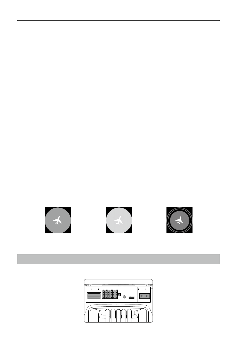
Warning Escalation:
The rst (or "lowest") level warning occurs three minutes away from the manned aircraft.
The second (or “middle”) level warning occurs two minutes away from the manned aircraft.
The third (or “highest”) level warning occurs one minute away from the manned aircraft.
Red: The third level warningBlue: The rst level warning Yellow: The second level warning
Expansion Ports
M210/M210 RTK provides several I/O ports, which can be customized in DJI Pilot app.
2017 DJI All Rights Reserved.
©
39
Page 40
MATRICE 200 Series User Manual
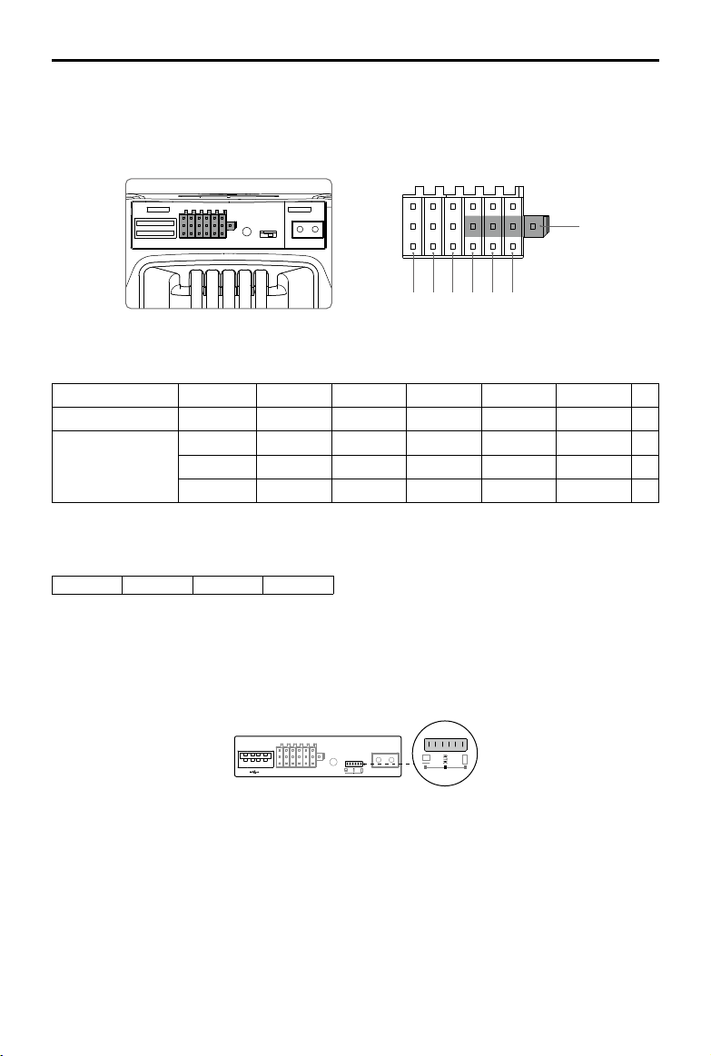
USB Port
USB port is used to connect orther devices, without power supply during ight.
Expansion Ports
1 2 3 4 5 6
Pins Descriptions
PWM power level is 3.3V and all pins can be congured in DJI Pilot app.
Number 1 2 3 4 5 6
Name OSDK port I/O port I/O port I/O port I/O port I/O port
Pins
(from up to down)
*Coming soon.
SDK_Tx IO/PWM5 IO/PWM4 IO/PWM3 IO/PWM2 IO/PWM1
SDK_Rx NC NC CANL CANH GND 5V
GND GND GND GND GND GND
CAN Bus Port can be used to connect to an expansion GPS module.
CANL CANH GND 5V
7
RC/Aircraft Linking Button and Indicator
Used to link between aircraft and Remote Controller, and the built-in LED will display the linking
status during linking procedure.
USB Mode Switch
Power on the Intelligent Flight Battery and toggle the USB Mode Switch left, and connect the aircraft
and the PC via a double A port USB cable for aircraft parameters configuration and firmware
update.
Toggle the USB Mode Switch to the middle RTK position, and connect the aircraft and the PC via a
double A port USB cable for the built-in D-RTK Air system activation and rmware update.
Toggle the USB Mode Switch right and connect the aircraft and mobile device via a Micro USB cable.
Extended Power Port (XT30)
Used to supply power for other device, whose voltage range is from 18 V to 26 V with a current of 2 A.
Make sure your device is satised with the voltage and current requirement.
2017 DJI All Rights Reserved.
©
40
Page 41
Remote Controller
This section describes the features of the
remote controller that includes aircraft
and remote controller operations and
dual remote controller mode.
Page 42

Remote Controller
Remote Controller Prole
The CendenceTM remote controller features DJI’s Lightbridge technology for a maximum transmission
distance of up to 4.3 mi (7 km).* Equipped with a DJI CrystalSkyTM 7.85 inch monitor, which offers an HD
live camera view with its built-in DJI Pilot app or DJI GOTM 4 app for a precise and responsive ying
experience. Dual transmission frequency support makes HD video downlink stable and reliable. In Dual
Remote Controller mode, two remote controllers can control the aircraft and camera separately and
simultaneously. Dual Remote Controller mode even works when users are up to 328 ft (100 m) apart.
The remote controller works with a WB37 intelligent battery, which can be charged via the charging
port (in about 2 hours and 24 minutes with a 180W charger) or with the WCH2 Intelligent Battery
Charging Hub (in about 1 hour and 11 minutes). The maximum operation time of the remote controller
is approximately four hours without supplying power to a monitor and with the Dual Remote Controller
mode disabled.*
With various customizable buttons, you can adjust a number of ight controller, camera, and gimbal
parameters with just your hands. The Cendence Patch Antenna also allows for high-gain signal
transmission and improved reception.
* The remote controller can reach its maximum transmission distance (FCC) in a wide open area with no
electro-magnetic interference at an altitude of about 400 feet (120 meters).
To comply with local regulations, the 5.8 GHz frequency is not available in some countries and regions.
Maximum run time is estimated without supplying power to a smart device or monitor.
Compliance Standards:
Stick Mode:
Mode 1:
Mode 2:
Please refer to the CrystalSky User Guide for more CrystalSky details.
Do not operate more than three aircraft within the same area (roughly the size of a soccer
eld) to prevent transmission interference.
Controls can be set to Mode 1, Mode 2, or to a custom mode.
The right stick serves as the throttle.
The left stick serves as the throttle.
The remote controller is compliant with local laws and regulations.
Preparing the Remote Controller
Mounting/Removing the Intelligent Battery
Put the battery into the Battery Slot, then slide it to the end until you hear a click.
OK
Press the Battery Release Button before removing the battery.
Press the Battery Level Button once to check the battery level.
Charging the Battery
The remote controller is powered by a WB37 intelligent battery, which can be charged via the
charging port or by the WCH2 Intelligent Battery Charging Hub.
2017 DJI All Rights Reserved.
©
42
Page 43
MATRICE 200 Series User Manual
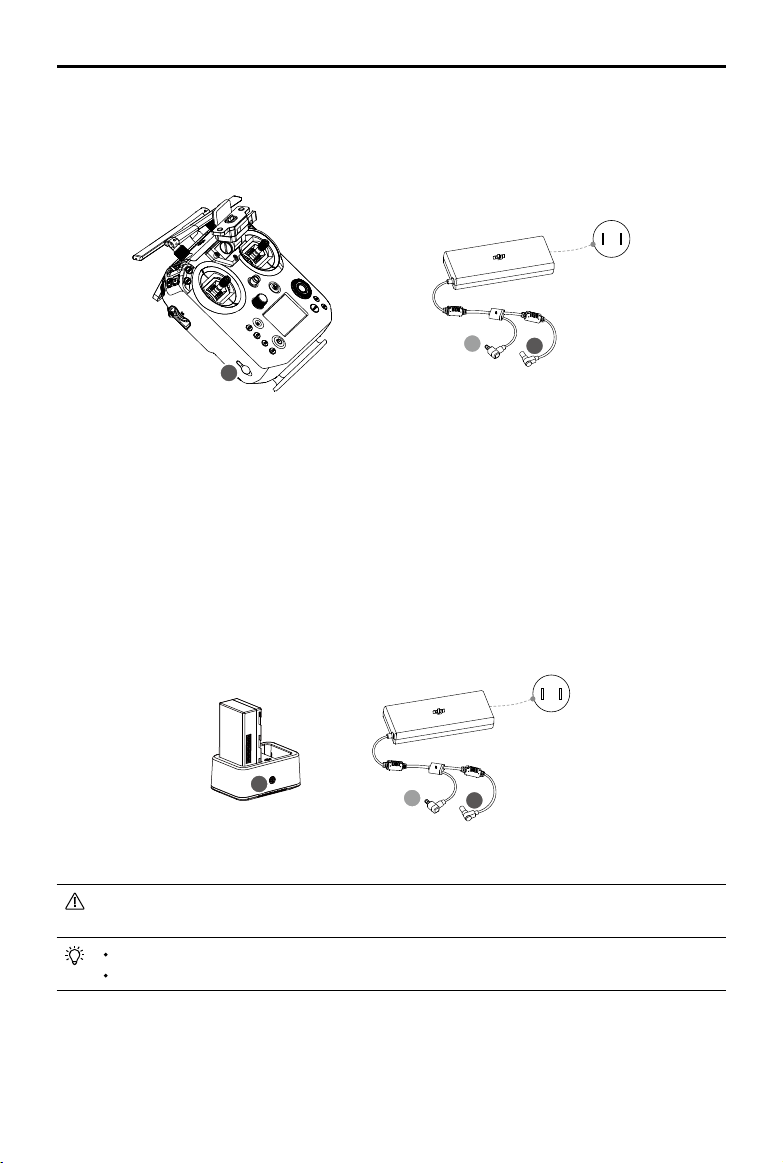
Using the Charging Port
Place the battery into the remote controller, and connect connector B of the battery power port, then
connect the battery charger to a power outlet (100-240V, 50/60Hz). When charging is complete, the
display on the remote controller will show 100%.
Power Qutlet
100~240 V
A
B
B
Charging Time: 2 hours and 24 minutes
Using the Charging Hub
Place the battery into the Charging Hub, and connect connector B of the battery charger to the
charging hub, then connect the battery charger to a power outlet (100-240V, 50/60Hz). The
Charging Hub will intelligently charge batteries in sequence according to battery power levels from
high to low. The buzzer will begin beeping when charging is complete. Remove the battery or turn
off the Buzzer Switch to stop it.
The charging hub blinks green while charging and turns solid green when charging is nished.
Power Qutlet
100~240 V
B
A
B
Using the WCH2 Charging Hub, charging time is approximately 1 hour and 11 minutes (for one battery).
Place the battery into the Charging Hub, and connect connector B of the battery charger to
the charging hub, then connect the battery charger to a power outlet (100-240V, 50/60Hz).
USB power supply port can be used to charge the mobile device of 5V/2A.
Refer to the WCH2 Charging Hub User Guide for more details.
2017 DJI All Rights Reserved.
©
43
Page 44

MATRICE 200 Series User Manual
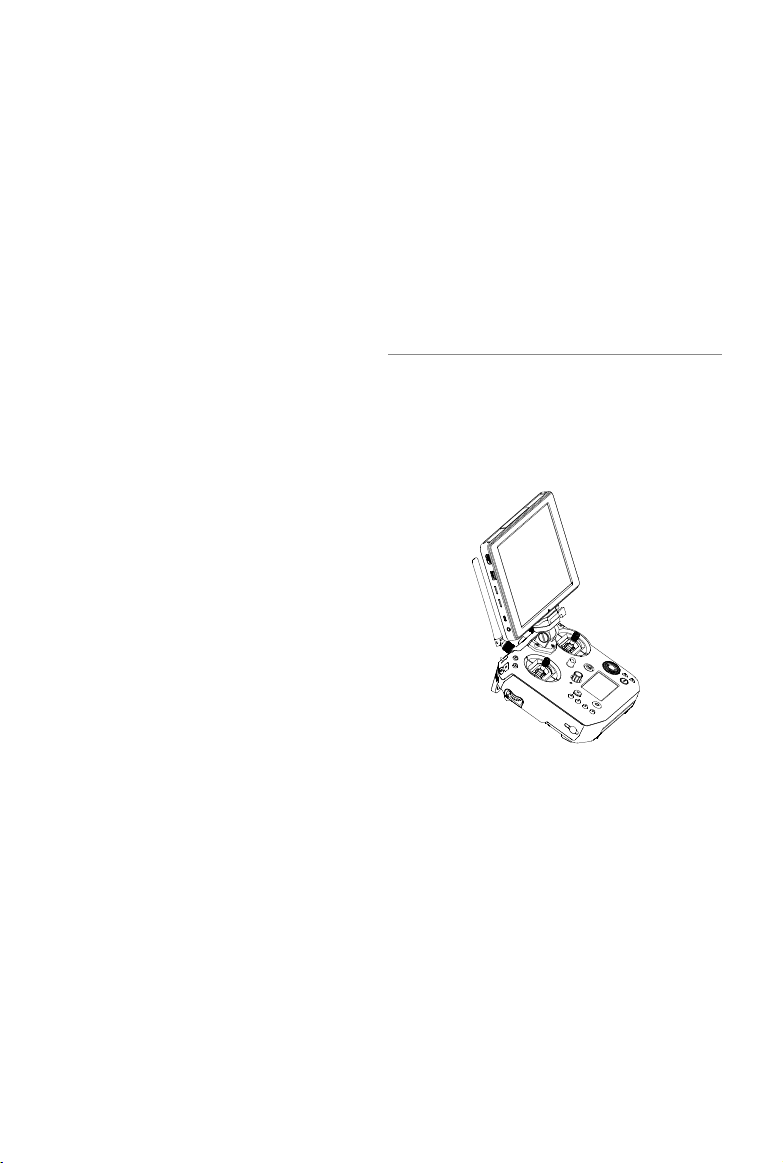
Mounting the Monitor to the Remote Controller
Mounting the DJI CrystalSky Monitor
Ensure that Part B is
unlocked. Install Part B
into Part A.
Lock the Mounting Bracket. Use a coin to adjust
the tightness of the
pitch axis.
Mounting the Other Mobile Devices
For other mobile devices (e.g. iPhones, iPads), the Cendence Mobile Device Holder and an
appropriate USB cable are required.
Unlock the Mounting Bracket and
mount the Mobile Device Holder.
Lock the Mounting Bracket.
Attach your mobile device, then tighten the clamp to secure it. Connect your mobile device to the
remote controller with a USB cable. Plug one end of the cable into your mobile device, and the
other end into the USB port on the back of the remote controller.
2017 DJI All Rights Reserved.
©
44
Page 45

MATRICE 200 Series User Manual
Remote Controller Operations
Button Types
Users can use the precongured buttons to control the aircraft and the camera and can also assign
functions to the customizable buttons through the DJI GO 4 app. There are three types of button:
1. Precongured buttons for aircraft control, e.g. the Pause Button, RTH Button, etc.
2. Preconfigured buttons for camera control, e.g. the Shutter Button, Recording Button, Focus
Adjustment Knob, etc.
3. Customizable buttons and knobs that you can set through the DJI GO 4 app.
Turning the Remote Controller On and Off
Follow the steps below to turn the remote controller on and off.
1. Press the power button once to check the current battery level. Charge the remote controller if
the battery is too low.
2. Next, press and hold the Power button to power on the remote controller.
3. Repeat step 2 to power off the remote controller after you nish using it.
2017 DJI All Rights Reserved.
©
45
Page 46

MATRICE 200 Series User Manual
Operating the Aircraft
Controlling the Aircraft
This section explains how to control the orientation of the aircraft through the remote controller.
Control can be set to Mode 1, Mode 2 or Mode 3, or to a custom mode.
Mode 1
Mode 2
Mode 3
Left Stick
Forward
Backward
Turn RightTurn Left
Right Stick
Right StickLeft Stick
UP
Down
Turn RightTurn Left
Left Stick Right Stick
Forward
UP
Down
RightLeft
Forward
Backward
RightLeft
UP
Backward
RightLeft
The Stick Mode is set to Mode 2 by default.
Stick Neutral/Mid-Point: Control sticks are centered.
Moving the Control Stick: Control sticks are pushed away from the center.
2017 DJI All Rights Reserved.
©
46
Down
Turn RightTurn Left
Page 47

Remote
Controller
(Mode 2)
Left Stick
Right Stick
Aircraft Remarks
Moving the left stick up and down changes the
aircraft’s elevation.
UP
Push the stick up to ascend and down to descend.
When both sticks are centered, the aircraft will
hover in place.
The more the stick is pushed away from the center
Down
position, the faster the aircraft will change elevation.
Always push the stick gently to prevent sudden
and unexpected elevation changes.
Moving the left stick to the left or right controls the
rudder and rotation of the aircraft.
Push the sick left to rotate the aircraft counter
clockwise, and push the stick right to rotate the
aircraft clockwise. If the stick is centered, the
Turn RightTurn Left
aircraft will maintain its current orientation.
The more the stick is pushed away from the center
position, the faster the aircraft will rotate.
Forward
Moving the right stick up and down changes the
aircraft’s forward and backward pitch.
Push the stick up to y forward and down to y
backward. The aircraft will hover in place if the stick is
centered.
Backward
Push the stick further away from the center position for a
larger pitch angle and faster ight.
Moving the right stick control left and right changes the
aircraft’s left and right pitch.
Push left to y left and right to y right. The aircraft will
RightLeft
hover in place if the stick is centered.
Push the stick further away from the center position for
a larger pitch angle and faster ight.
MATRICE 200 Series User Manual
Flight Mode Switch
Toggle the switch to select the desired ight mode. Choose between; P-mode, S-mode, and A-
mode.
Position 1
Position Figure Flight Mode
Position 1 P-mode
Position 2
Position 3
Position 2 S-mode
Position 3 A-mode
2017 DJI All Rights Reserved.
©
47
Page 48
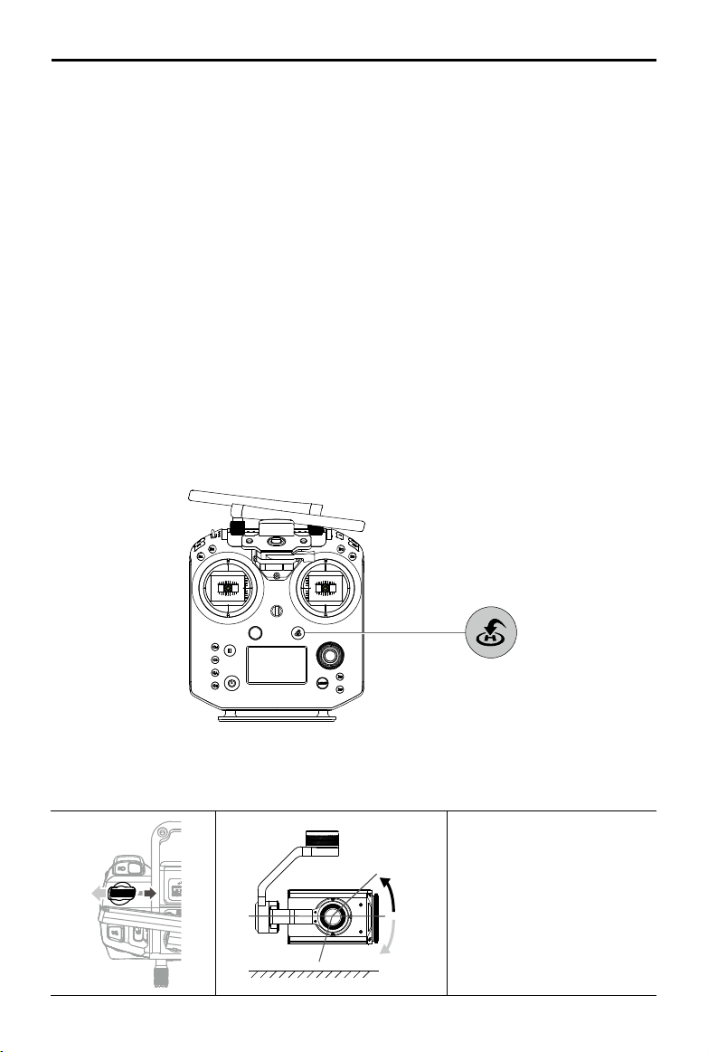
MATRICE 200 Series User Manual
P-mode (Positioning):
P-mode works best when the GPS signal is strong. The aircraft utilizes GPS,
stereo Vision Systems, and an Infrared Sensing System to stabilize, avoid obstacles or track moving
subjects. Advanced features such as TapFly and ActiveTrack are enabled in this mode.
S-mode (Sport):
The handling gain values of the aircraft are adjusted to enhance aircraft
maneuverability. Note that Obstacle Sensing systems are disabled in this mode.
A-mode (Attitude):
When neither the GPS nor the Vision System is available, the aircraft will only use
its barometer for positioning to control the altitude.
The Flight Mode Switch is locked to P-mode, regardless of the Flight Mode Switch's position. To
change ight modes, go to the Camera View in DJI GO 4 and enable Multiple Flight Modes in Main
Controller Settings. After enabling multiple ight modes, toggle the switch to P for Position mode
and S for Sport Mode.
RTH Button
Press and hold the RTH button to start the Return to Home (RTH) procedure. The aircraft will then
return to the last recorded Home Point. Press this button again to cancel the RTH procedure and
regain control of the aircraft.
Determine RTH status by sound:
Single beep... Request to return, but not receive the respond from the aircraft yet.
Double beep... RTH in progress.
Controlling the Gimbal
Use the left dial and right dial to adjust the gimbal tilt.
-130°
2017 DJI All Rights Reserved.
©
48
+40°
0°
horizon
The left dial controls the gimbal
tilt. Turn the dial to the right,
and the gimbal will shift to point
upwards. Turn the dial to the
left, and the gimbal will shift to
point downwards. The camera
will remain in its current position
when the dial is static.
Page 49
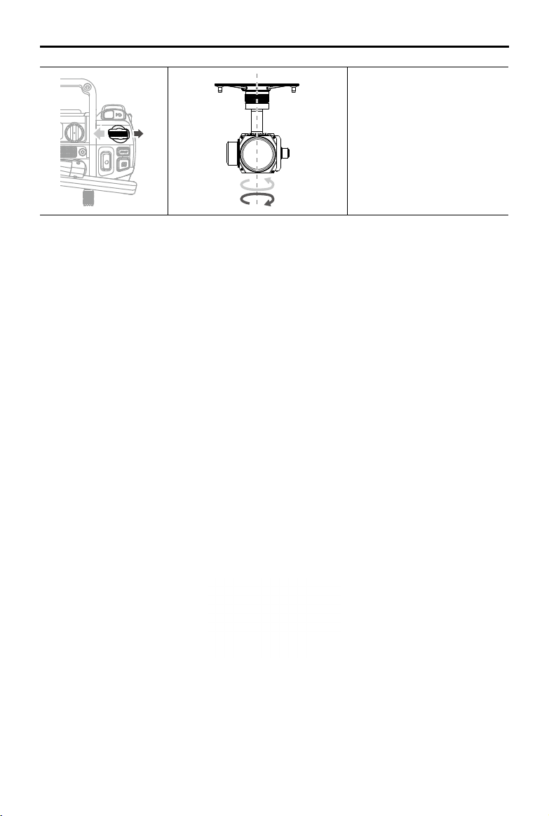
MATRICE 200 Series User Manual
The right dial controls the
gimbal pan. Turn the dial to the
right, and the gimbal will shift
clockwise. Turn the dial to the
left, and the gimbal will shift
counter clockwise. The camera
-320°
+
320°
will remain in its current position
when the dial is static.
Operating the Camera
Shoot videos/photos with the Shutter Button and Video Recording Button on the remote controller.
1. Shutter Button
Press to take a photo. If Burst mode is selected, multiple photos will be taken with a continuous
press. Photos can be taken even while recording video.
2. Video Recoding Button
Press once to start recording video, then press again to stop recording.
3. Autofocus button
Press once to focus automatically.
Setting the Camera
1. EV Setting
Press EV Setting Button and rotate the Camera Setting Dial at the same time to set the EV value.
2. Shutter Setting
Press Shutter Setting Button and rotate the Camera Setting Dial at the same time to set the
shutter speed.
3. Aperture Setting
Press Aperture Setting Button and rotate the Camera Setting Dial at the same time to set the
aperture value.
4. ISO Setting
Press ISO Setting Button and rotate the Camera Setting Dial at the same time to set the ISO
value.
5. Focus Adjustment
Rotate Focus Adjustment Knob to set the focal length.
2017 DJI All Rights Reserved.
©
49
Page 50
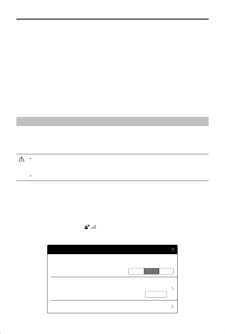
MATRICE 200 Series User Manual
Conguring the Customizable Buttons
Go to the Customizable Button Settings Menu in DJI GO 4. Here you can set functions for the left
lever, right lever, C1-C4 buttons, and BA-BH buttons.
Dual Remote Controller Mode
More than one remote controller can connect to the same aircraft in Dual Remote Controller mode.
The Master remote controller operator controls the orientation of the aircraft, while the Slave remote
controller controls the movement of the gimbal and camera operation. Master and Slave remote
controllers communicate each other via Wi-Fi.
In Dual Controller Mode, when the Master remote controller is primary, it can control
gimbal pitch and pan. When the Slave remote controller is primary, it can control gimbal
pitch, pan, and roll.
Dual Remote Controller mode is not available in Russia and Israel.
Setting Up Dual Remote Controller Mode
Dual Remote Controller mode is disabled by default. Users must enable this feature on the Master
remote controller via DJI GO 4. Follow the steps below to setup:
Master Remote Controller:
1. Connect the remote controller to your mobile device and launch DJI GO 4.
2. Go to the Camera View and tap to enter the remote controller settings window.
3. Select Master and set the remote controller as the Master remote controller.
4. Enter the connection password for the Slave remote controller.
Remote Controller Settings
Master and Slave
Master
Slave
666666
2017 DJI All Rights Reserved.
©
50
Set Remote Controller Status
Master ID: 28172d Slave ID: 14f93f
Connection Status:ON Authorization Code:
Remote Controller Calibration
OFF
Page 51
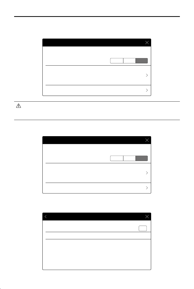
MATRICE 200 Series User Manual
“Slave” Remote Controller:
1. Select Slave to set the remote controller to Slave.
Remote Controller Settings
Master and Slave
Master
Set Remote Controller Status
Master ID: 28172d Slave ID: 14f93f
Connection Status:OFF
Search Master
OFF
Slave
When in Slave, the remote controller cannot link to the aircraft nor control aircraft orientation.
Select Master in DJI GO 4 if you wish to connect and control the aircraft with the remote
controller.
2. Search the “Master” remote controller in the surrounding area.
Remote Controller Settings
Master and Slave
Master
Set Remote Controller Status
OFF
Slave
Master ID: 28172d Slave ID: 14f93f
Connection Status:OFF
Search Master
3. Select the Master remote controller from the Master list and input the password to connect.
Search Master
Master
2816f2
28172d
RSSI
-56.00
-22.00
Scan
Connect
Connect
2017 DJI All Rights Reserved.
©
51
Page 52
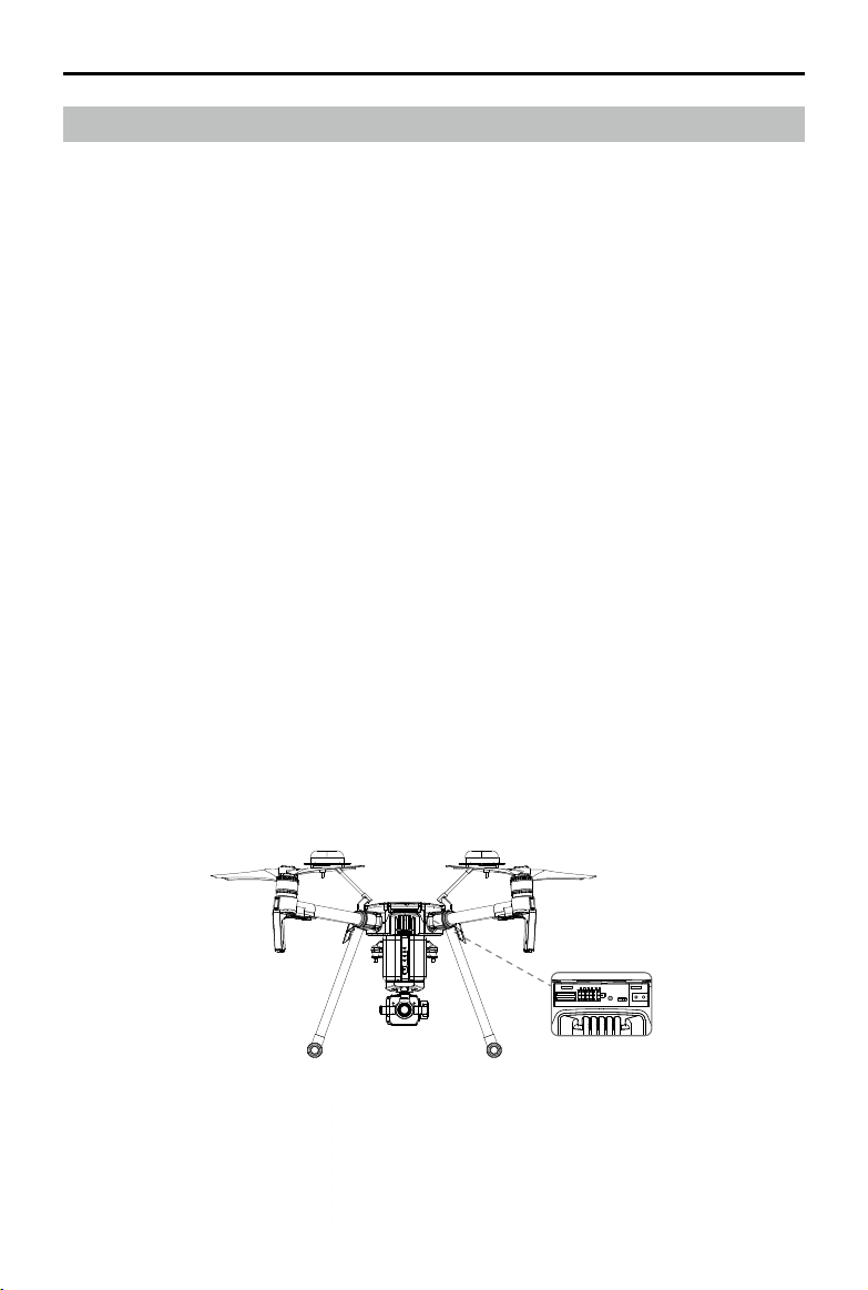
MATRICE 200 Series User Manual
Linking the Remote Controller
The remote controller comes linked to your aircraft before delivery. Linking is only required when
using for the remote controller for the rst time. Follow these steps to link a remote controller:
1. Power on the remote controller, connect to your mobile device, and launch DJI GO 4.
2. Power on the Intelligent Flight Battery.
3. Enter the Camera View and tap the Linking Remote Controller button shown below.
4. The DJI GO 4 app will display a countdown box, the remote controller will be ready to link, with
its display showing Connecting and a beeping sound being emitted.
5. Locate the Linking button on the aircraft and press the Linking button to start linking. The remote
controller display shows the current status information. The master remote controller shows the
aircraft status, and the slave remote controller shows the camera settings.
2017 DJI All Rights Reserved.
©
52
Page 53

MATRICE 200 Series User Manual
A Slave remote controller cannot link to the aircraft and so therefore cannot control the
orientation of the aircraft. Select Master in DJI GO 4 if you wish to link a remote controller it
to the aircraft.
A remote controller will disconnect from the linked aircraft if a new remote controller is
linked to the same aircraft.
Press the C1 and C2 buttons and the Start/Stop button for fast linking.
2017 DJI All Rights Reserved.
©
53
Page 54
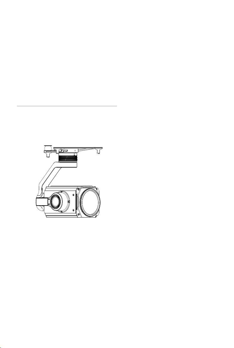
Gimbal and Camera
This section focuses on the technical
specications of the camera and explains
how to use the gimbal.
Page 55
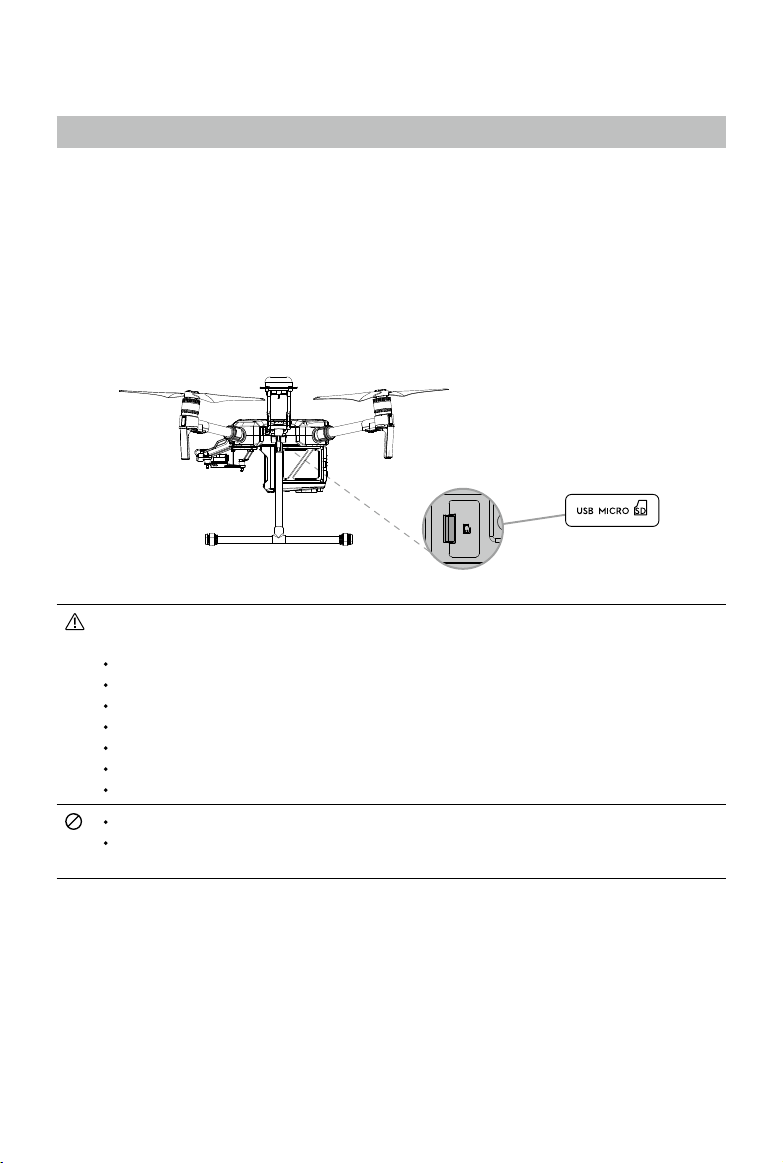
Gimbal and Camera
Camera
Camera Prole
Using the Zenmuse Z30 as an example, this section will demonstrate the technical specications of
the camera while explaining how to use the gimbal.
Camera Micro SD Card Slot
To store photos and videos, plug the Micro SD card into the slot shown below before powering
on the aircraft. The aircraft comes with a 16 GB Micro SD card and can support card sizes of up
to 128 GB. We recommend you use a UHS-3 type Micro SD card because the fast read and write
capability of these cards enables you to store high-resolution video data.
The Matrice 210/210 RTK currently supports the following Micro SD cards, and will continue
to support more cards in future.
SanDisk Extreme 32GB UHS-3 microSDHC
SanDisk Extreme 64GB UHS-3 microSDXC
Panasonic 32GB UHS-3 microSDHC
Panasonic 64GB UHS-3 microSDXC
Samsung PRO 32GB UHS-3 microSDHC
Samsung PRO 64GB UHS-3 microSDXC
Samsung PRO 128GB UHS-3 microSDXC
Do not remove Micro SD card from the aircraft when it is powered on.
To ensure the stability of the camera system, single video recordings are capped at 30
minutes.
Camera Operation
Remote Controller
Use the Shutter and Record buttons on the remote controller to shoot photos or videos. For more
information on how to use these buttons, please refer to Controlling the Camera.
DJI GO 4
Use DJI GO 4 to shoot photos or videos. For more information, refer to the camera and gimbal User
Manual.
2017 DJI All Rights Reserved.
©
55
Page 56

MATRICE 200 Series User Manual
ISO
SHUT TER
EV
F
SD TIME
WB
Gimbal
Gimbal Prole
The 3-axis gimbal provides a steady platform for the attached camera, allowing you to capture
stabilized images and video.
+40°
0°
-130°
horizon
-320°
+320°
Using the DJI GO 4 App to Control Gimbal
Follow the steps below to use the DJI GO 4 app to control gimbal orientation:
1. Launch DJI GO 4 and enter the Camera View.
2. Tap and press on the screen until a blue circle is shown.
3. Slide to control the gimbal's orientation within the Camera View as shown below.
In Flight (GPS)
P-GPS
200 0.3
5.61/200 20:12
Custom
5000K
12
09:29
4KP30
74%
70%
AF/ MF
4.07V
4.07V
+20°
-20°
AE
2017 DJI All Rights Reserved.
©
56
30m
D
H
10.0
VS 2.0m/s VPS 2.0mH.S 10.0km/h
m
Page 57

MATRICE 200 Series User Manual
Gimbal Operation Modes
Three gimbal operation modes are available. Switch between the different operation modes in DJI
GO 4's Camera View. Note that your mobile device must be connected to the remote controller for
changes to take effect. Refer to the table below for details:
Pitch Pan
Roll
Follow Mode Gimbal pan cannot be controlled in this mode.
Free Mode The Gimbal’s motion is independent of the aircraft’s orientation.
Reset
Tap and the gimbal will pan to realign with the aircraft's nose. The tilt
angle will remain unchanged during re-alignment.
Gimbal pan cannot be controlled in Follow Mode. In Free Mode, press and hold the C1
Button while rotating the control dial to adjust gimbal yaw.
The gimbal will be in free mode when the Slave remote controller controls the gimbal in
Dual Remote Controller Mode.
2017 DJI All Rights Reserved.
©
57
Page 58

DJI GO 4
This section introduces the main
functions of the DJI GO 4 app.
Page 59
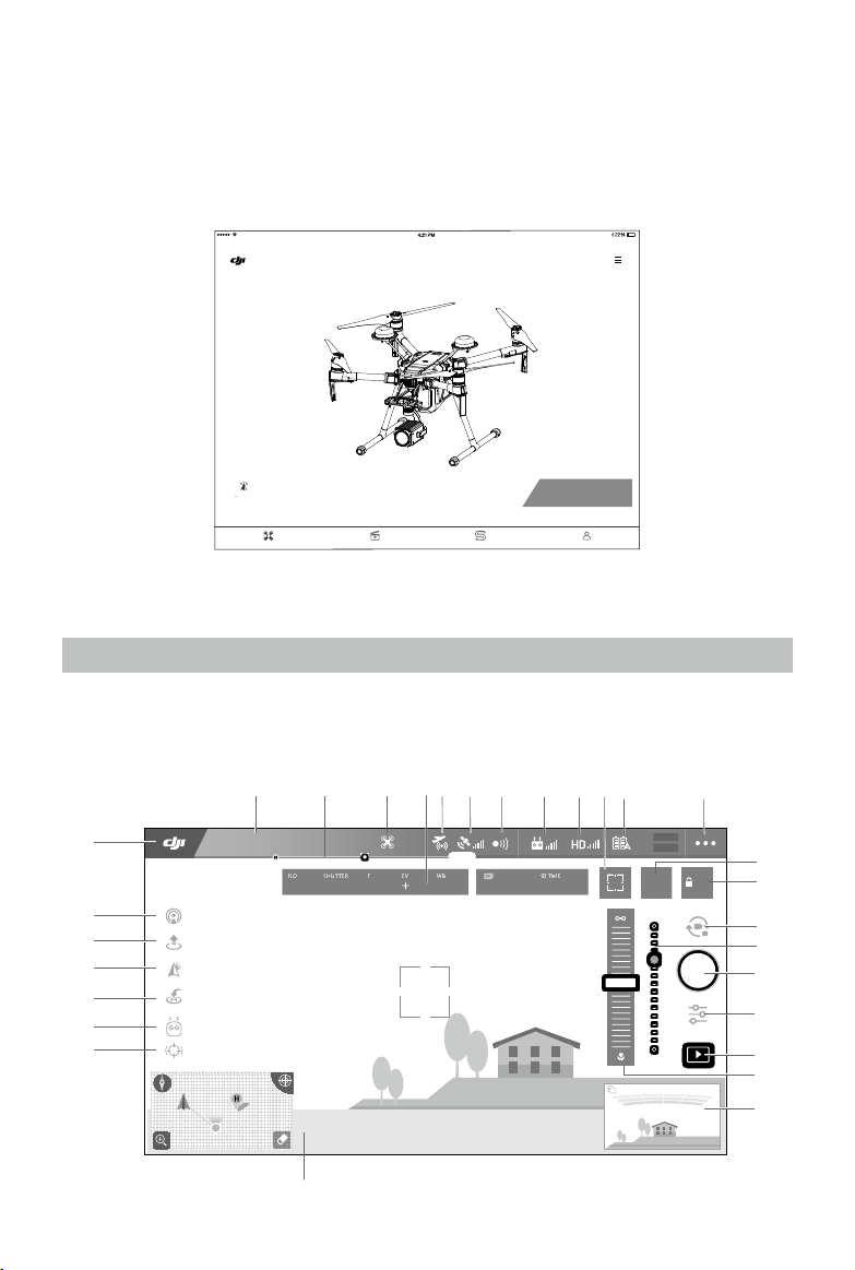
DJI GO 4
ISO
SHUT TER
EV
F
SD TIME
WB
Use the DJI GO 4 app to control the gimbal, camera, and other aircraft functions. The app features
Equipment, Editor, SkyPixel, and Me sections, which are used for conguring your aircraft, editing,
and sharing your photos and videos with others. It is recommended that you use a tablet for the
best possible experience.
MATRICE 210
Be aware of local flight regulations
before flying!
CONNECTED
Equipment
Editor Skypixel
GO FLY
Me
Both DJI GO 4 and DJI Pilot support the Zenmuse X5S, X4S, and Z30. DJI Pilot is required if using the
Zenmuse XT. This manual uses DJI GO 4 as an example. Please refer to the actual user interface.
Equipment
Enter the Camera View by tapping the GO FLY icon on the Equipment page when your mobile
device is connected to the aircraft.
Camera View
7
Custom
6
12
09:29
8
10 11
9
4KP305000K
1 2 3 4 5
29
READY TO GO (GPS)
200 0.3
P-GPS
5.61/200 20:12
28
27
26
25
24
23
30m
D
km/h
H
10.0
VS 2.0
m
m/s
VPS 2.0mH.S 10.0
74%
70%
AF/ MF
12
4.07V
4.07V
AE
13
14
15
16
17
18
19
20
21
22
2017 DJI All Rights Reserved.
©
59
Page 60

MATRICE 200 Series User Manual
1. System Status
READY TO GO (GPS)
: This icon indicates aircraft ight status and displays various warning messages.
2. Battery Level Indicator
: The battery level indicator provides a dynamic display of the battery level. The colored
zones on the battery level indicator represent the power levels needed to carry out different
functions.
3. Flight Mode
: The text next to this icon indicates the current ight mode.
Tap to congure the Flight Controller Settings. These settings allow you to modify ight limits and
set gain values.
4. Camera Parameters
Displays camera settings parameters and capacity of the Micro SD card.
(1) Tap to set white balance parameters.
(2) Tap to set photo and video parameters.
5. AirSense Status
: AirSense Status displays information about nearby manned aircraft to ensure flight safety,
including the distance between DJI aircraft and manned aircraft. AirSense will instruct users to land if
nearby aircraft are detected.
6. GPS Signal Bars
: Shows current GPS signal strength. Four GPS signal bars indicates sufcient GPS strength
to return to home.
7. Obstacle Sensing Function Status
: Tap this icon to enable or disable features provided by the Vision System.
8. Remote Controller Signal Bars
: This icon shows the strength of the remote controller signal.
9. HD Video Link Signal Bars
: This icon shows the strength of the HD video downlink connection between the aircraft
and remote controller.
10. Focus/Metering Button
/ : Tap to switch between the focus and metering modes. Tap to select an object for
focusing or metering.
2017 DJI All Rights Reserved.
©
60
Page 61

MATRICE 200 Series User Manual
11. Battery Level
: This icon shows current battery level.
Tap to view the battery information menu, set various battery warning thresholds, and view
battery warning history.
12. General Settings
: Tap to enter the General Settings menu to set metrics to enable live streaming, display
ight routes, and so on.
13. AF/MF
: Tap to switch the focus mode.
14. Auto Exposure Lock
: Tap to lock the exposure value.
AE
15. Photo/Video Toggle
: Tap to switch between photo and video recording modes.
16. Gimbal Slider
: Displays the pitch of the gimbal.
17. Shoot / Record Button
/ : Tap to start shooting photos or recording video.
18. Camera Settings
: Tap to set ISO, shutter and auto exposure values of the camera.
19. Playback
: Tap to enter the playback page and preview photos and videos as soon as they are captured.
20. Manual Focus
Only effective in MF mode.
21. FPV
FPV is only available on tablets. Pinch to zoom in or out of the window.
: Red bars are displayed when obstacles are close to the aircraft. Orange bars are
displayed when obstacles are in detection range.
:Tap to zoom in on the FPV window and move it to the middle of the screen.
2017 DJI All Rights Reserved.
©
61
Page 62

MATRICE 200 Series User Manual
22. Flight Telemetry
(1) Tap to switch to map view.
(2) Flight Attitude and Radar Function:
N
The red arrow shows which direction the aircraft is facing.
The ratio of gray area to blue area indicates the aircraft’s pitch.
The horizontal level of the gray area indicates the aircraft’s roll angle.
A blue line indicates the current position of the gimbal’s tilt motor.
The outermost gray circle displays the current power capacity.
(3) Flight Parameters:
Altitude: Vertical distance from the Home Point.
Distance: Horizontal distance from the Home Point.
Vertical Speed: Movement speed across a vertical distance.
Horizontal Speed: Movement speed across a horizontal distance.
(4) Aircraft Distance:
The horizontal distance between the aircraft and the operator.
23. Spotlight Pro
:Tap to use the Spotlight Pro function.
24. Intelligent Flight Mode
: Displays the current mode. Tap to select Intelligent Flight Mode.
25. Smart RTH
: Initiate RTH procedure. Tap to have the aircraft return to the last recorded home point.
26. Gimbal Working Modes
Follow mode, free mode and reset mode are included.
27. Auto Takeoff/Landing
/ : Tap to initiate auto takeoff or landing.
28. Livestream
: This icon indicates that the current video feed is being broadcast live on YouTube. Ensure
a mobile data service is available on your mobile device.
29. Back
: Tap this icon to return to the main menu.
2017 DJI All Rights Reserved.
©
62
Page 63

MATRICE 200 Series User Manual
Editor
A dedicated video editor is built into the DJI GO 4 app. After recording several video clips and
downloading them to your mobile device, go to Editor on the home screen. You can then select
a template and a specied number of clips that automatically combine, creating a short lm for
sharing.
SkyPixel
View and share photos and videos on the SkyPixel page.
Me
If you already have a DJI account, you will be able to participate in forum discussions, and share
your creations with the community.
2017 DJI All Rights Reserved.
©
63
Page 64
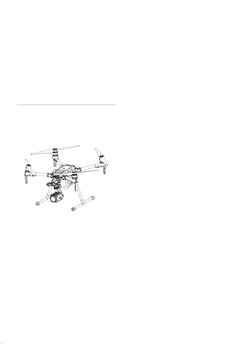
Flight
This section describes safe ight
practices and ight restrictions.
Page 65

Flight
Ensure that all flights are carried out in an open area. It is important to understand basic flight
guidelines for the safety of both you and those around you. Refer to the Disclaimer and Safety
Guidelines for more information.
Flight Environment Requirements
1. Do not use the aircraft in severe weather conditions. These include wind speeds exceeding 10
m/s, snow, rain, and fog.
2. When ying in open areas, tall and large metal structures may affect the accuracy of the onboard
compass and GPS system.
3. Avoid obstacles, crowds, high voltage power lines, trees, and bodies of water.
4. Minimize interference by avoiding areas with elevated levels of electromagnetism, including base
stations and radio transmission towers.
5. Aircraft and battery performance is subject to environmental factors such as air density and
temperature. Be very careful when ying at high altitudes, as battery and aircraft performance
may be affected.
6. The compass and GNSS will not work in Polar Regions. The aircraft will have to auto switch to
A-mode, using the Vision System for positioning.
Flight Limits and No-Fly Zones
All unmanned aerial vehicle (UAV) operators should abide by all regulations set forth by government
and regulatory agencies including the ICAO and the FAA. For safety reasons, ights are limited by
default, which helps users operate this product safely and legally. Flight limitations include height
limits, distance limits, and No-Fly Zones.
When operating in P-mode, height limits, distance limits, and No-Fly Zones function concurrently to
manage ight safety. In A-mode, only height limits are in effect, which by default prevent the aircraft
altitude from exceeding 1640 feet (500 m) .
Maximum ight altitude & Radius Limits
Maximum ight altitude and radius limits may be changed in the DJI GO 4 app. Be aware that the
maximum ight altitude cannot exceed 1640 feet (500 meters). In accordance with these settings,
your aircraft will y in a restricted cylinder, as shown below:
Maximum Flight Altitude
Max Radius
Home Point
Height of aircraft
when turned on
2017 DJI All Rights Reserved.
©
65
Page 66
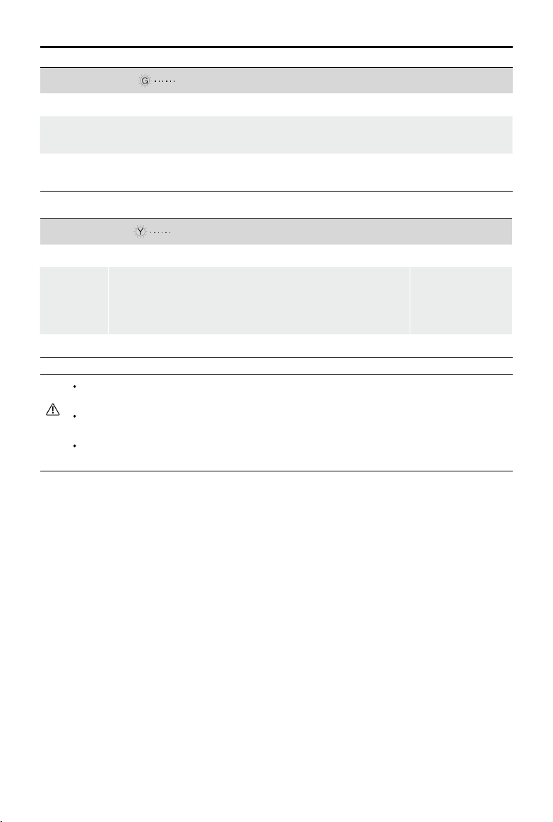
MATRICE 200 Series User Manual
GPS Signal Strong Blinking Green
Flight Limits DJI GO 4 App
Maximum Flight
Altitude
Max Radius Flight distance must be within the max radius.
GPS Signal Weak Blinking Yellow
Maximum
Flight
Altitude
Max Radius No Limits
If the aircraft ies out of the limit, you can still control the aircraft, but you cannot y it any
farther.
If the aircraft ies out of the max radius it will y back within range automatically when GPS
signal is strong.
For safety reasons, please do not y close to airports, highways, railway stations, railway
lines, city centers, or other sensitive areas. Fly the aircraft only within your line of sight.
Aircraft's altitude cannot exceed the specied value.
Flight Limits DJI GO 4 App
Height is restricted to 26 feet (8 meters) when the GPS signal
is weak and Vision Positioning is active. Height is restricted
to 98 feet (30 meters) when the GPS signal is weak and
Vision Positioning is inactive.
Warning: Height
limit reached.
Warning: Distance
limit reached.
Warning:
Height limit
reached.
No-Fly Zones
All No-Fly Zones are listed on the DJI ofcial website at http://www.dji.com/ysafe/no-y. No-Fly Zones
are divided into Airports and Restricted Areas. Airports include major airports and ying elds where
manned aircraft operate at low altitudes. Restricted Areas include country borders or locations where
ights may cause security concerns. The details of the No-Fly Zones are explained below:
Airport:
(1) Airport No-Fly Zones comprise of Takeoff Restricted Zones and Restricted Altitude Zones. Each
zone features circles of various sizes.
(2) R1 miles depends on the shape and size of the airport and is an area around the airport that is a
Takeoff Restricted Zone, within which takeoff and ight are prohibited.
(3) From R1 mile to R1 + 1 mile around the airport the ight altitude is restricted to a 15-degree
inclination, starting at 65 feet (20 meters) from the edge of the airport and radiating outward.
Flight altitude is limited to 1640 feet (500 meters) at R1+1 mile.
2017 DJI All Rights Reserved.
©
66
Page 67

MATRICE 200 Series User Manual
R1
66 feet
1 mile
R2
Airports
(4) When the aircraft ies within 320 feet (100 meters) of a No-Fly Zone, a warning message will
appear in DJI GO 4.
Airports
1640
feet
66 feet
320 feet
Restricted Areas:
1 mile
R2
R1
(1) Restricted Areas do not have ight altitude restrictions.
(2) R miles around the designated restriction area is a Takeoff Restricted area. Aircraft cannot take
off within this zone. The value of R varies based on the denition of the restricted areas.
(3) A “warning zone” has been set around the Restricted Area. When the aircraft approaches within
0.062 miles (100 m) of this zone, a warning message will appear in DJI GO 4.
Restricted Areas
100m R
When flying in a safety zone, the aircraft's status indicator will blink red rapidly and
continue for three seconds, then switch to indicate current ying status and continue for
ve seconds at which point it will switch back to blinking red.
For safety reasons, please do not y close to airports, highways, railway stations, railway
lines, city centers, or other sensitive areas. Fly the aircraft only within your line of sight.
2017 DJI All Rights Reserved.
©
67
Page 68
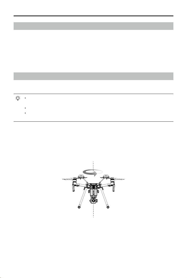
MATRICE 200 Series User Manual
Preight Checklist
1. Remote controller, Intelligent Flight Battery, and mobile device are fully charged.
2. Propellers are mounted correctly and rmly.
3. Micro SD card has been inserted, if necessary.
4. Gimbal is functioning normally.
5. Motors can start and are functioning normally.
6. The DJI GO 4 app is successfully connected to the aircraft.
7. Ensure that the sensors for the Obstacle Sensing System are clean.
Calibrating the Compass
Only calibrate the compass when the DJI GO 4 app or the status indicator prompts you to do so.
Observe the following rules when calibrating your compass:
DO NOT calibrate your compass where there is a chance of strong magnetic interference,
such as near magnets, parking structures, or steel reinforcements underground.
DO NOT carry ferromagnetic materials with you during calibration such as cellular phones.
The DJI GO 4 app will notify you if the compass is affected by strong interference after
calibration is complete. Follow the prompts to resolve the compass issue.
Calibration Procedures
Choose an open area to carry out the following procedures.
1. Tap the Aircraft Status Bar in the app and select Calibrate, then follow the on-screen instructions.
2. Hold the aircraft horizontally and rotate it 360 degrees. The Aircraft Status Indicators will go solid
green.
2017 DJI All Rights Reserved.
©
68
Page 69
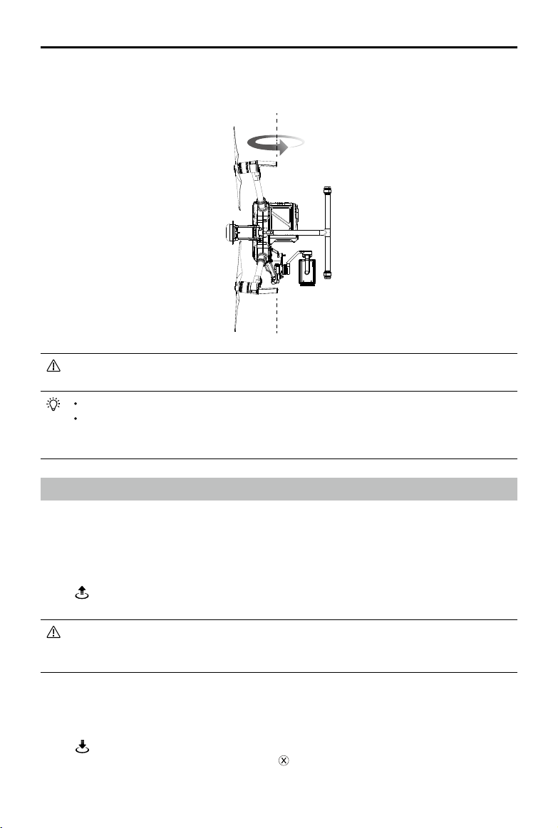
MATRICE 200 Series User Manual
3. Hold the aircraft vertically, with the nose pointing downward, and rotate it 360 degrees around
the center axis. Re-calibrate the aircraft if the aircraft status indicators blink red.
If the Aircraft Status Indicator blinks red and yellow after the calibration procedure, move
your aircraft to a different location and try again.
DO NOT calibrate the compass near metal objects such as a metal bridge, cars, scaffolding.
If the aircraft status indicators are blinking red and yellow alternately after placing the aircraft
on the ground, the compass has detected magnetic interference. Please change your
location.
Auto Takeoff and Auto Landing
Auto Takeoff
Use auto takeoff only if the Aircraft Status Indicators are blinking green. Follow the steps below to
use the auto takeoff feature:
1. Launch the DJI GO 4 app and tap GO FLY to enter Camera View.
2. Complete all steps on the pre-ight checklist.
3. Tap“ ”, and conrm that conditions are safe for ight. Slide the icon to conrm and takeoff.
4. Aircraft takes off and hovers at (1.2 meters) above ground.
Aircraft Status Indicator blinks rapidly when it is using the Vision System for stabilization.
The aircraft will automatically hover below 10 meters. It is recommended to wait until there
is sufcient GPS lock before using the Auto Takeoff feature.
Auto-Landing
Use auto-landing only if the Aircraft Status Indicator is blinking green. Follow the steps below to use
the auto-landing feature:
1. Tap , to ensure that landing conditions are ideal. Slide to conrm.
2. Abort landing process immediately by tapping on the screen.
2017 DJI All Rights Reserved.
©
69
Page 70
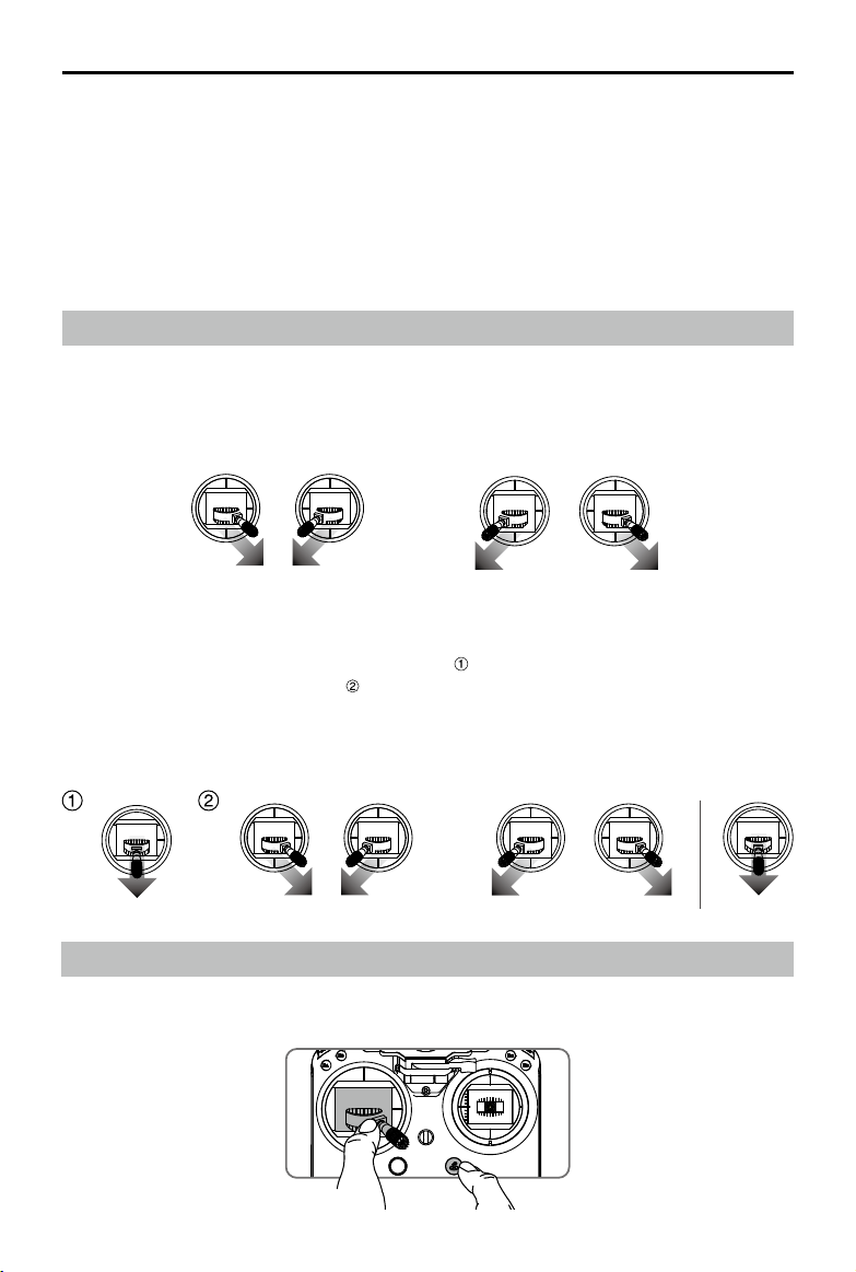
MATRICE 200 Series User Manual
3. a. When Landing Protection determines that the ground is suitable for landing, the aircraft will
land gently.
b. If Landing Protection determines that the ground is not suitable for landing, the aircraft will
hover and wait for pilot conrmation.
c. If Landing Protection is not operational, the DJI GO 4 app will display a landing prompt when
the aircraft descends below 0.7 meters. Pull down on the throttle or use the auto landing slider
to land.
4. The aircraft will land and turn off automatically.
Starting/Stopping the Motors
Starting Motors
The Combination Stick Command (CSC) is used to start the motors. Push both sticks to the bottom
inner or outer corners to start the motors. Once the motors start spinning, release both sticks simultaneously.
OR
Stopping the Motors
There are two ways to stop the motors:
1: When aircraft has landed, push the left stick down , then conduct the same CSC that was used
to start the motors, as shown above . Motors will stop immediately. Release both sticks once
motors stop.
2: When the aircraft has landed, push and hold the left stick down. The motors will stop after three
seconds.
OR
Method 1 Method 2
Stop the Motor Mid-ight
Pull the left stick to the bottom right inside corner and press the RTH button at the same time.
the motors mid-f light in emergency situations when doing so reduces the risk of damage or injury.
2017 DJI All Rights Reserved.
©
70
Only stop
Page 71
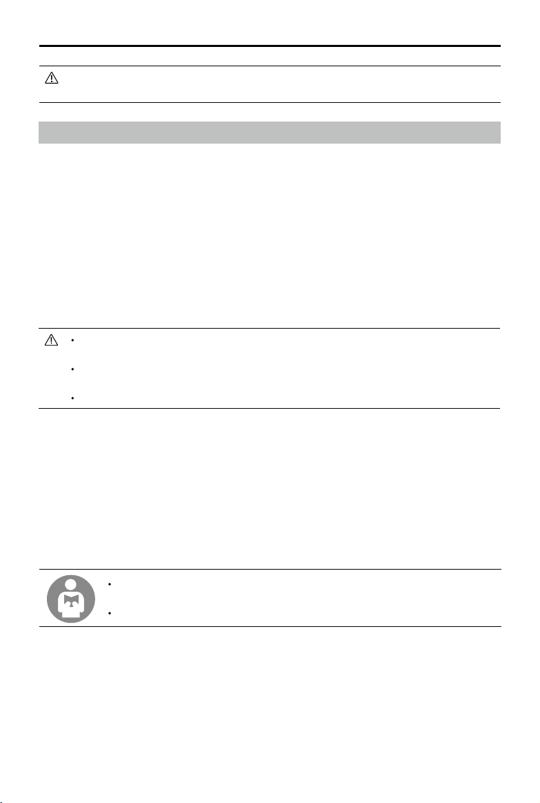
MATRICE 200 Series User Manual
Please check that CSC is activated inside DJI GO 4 app, then the user can stop the
aircraft mid-air.
Flight Test
Takeoff/Landing Procedures
1. Place the aircraft in an open, at area with the battery level indicators facing towards you.
2. Turn on the remote controller and your mobile device, then turn on the Intelligent Flight Battery.
3. Launch DJI GO 4 and enter the Camera View.
4. Wait until the Aircraft Indicators blink green. This means the Home Point has been recorded and
it is now safe to y. If they ash yellow, the Home Point has not been recorded.
5. Turn on the motors using CSC and push the left stick up slowly or use Auto Takeoff to take off.
6. Shoot photos and videos using the DJI GO 4 app.
7. To land, hover over a level surface and gently pull down on the left stick to descend.
8. After landing, execute the CSC command or hold the left stick at its lowest position until the motors stop.
9. Turn off the Intelligent Flight Battery rst, then the remote controller..
When the Aircraft Status Indicators blink yellow rapidly during ight, the aircraft has entered Failsafe
mode.
A low battery level warning is indicated by the Aircraft Status Indicators blinking red slowly
or rapidly during ight.
Watch our video tutorials for more ight information.
Video Suggestions and Tips
1. Go through the full pre-ight checklist before each ight.
2. Select the desired gimbal operation mode in the DJI GO 4 app.
3. Only shoot video when ying in P-mode.
4. Always y in good weather and avoid ying in rain or heavy wind.
5. Choose the camera settings that suit your needs. Settings include photo format and exposure
compensation.
6. Perform ight tests to establish ight routes and preview scenes.
7. Push the control sticks gently to keep the aircraft’s movement smooth and stable.
It is important to understand basic ight guidelines for the safety of both you and
those around you.
Refer to the Disclaimer and Safety Guidelines for more information.
2017 DJI All Rights Reserved.
©
71
Page 72

Appendix
Page 73

Appendix
Specications
Aircraft
Model
Dimensions
Diagonal Wheelbase 643 mm
Max Takeoff Weight 6.14 kg
Max Payload
Hovering Accuracy (P-mode with GPS)
Max Angular Velocity Pitch: 300°/s, Yaw: 150°/s
Max Pitch Angle
Max Ascent Speed 16.4 ft/s (5 m/s)
Max Descent Speed (Vertical) 9.8 ft/s (3 m/s)
Max Speed
Max Service Ceiling Above Sea Level 9842 feet (3000 m, with 1760S propellers)
Max Wind Resistance 39.36 ft/s (12 m/s)
Max Flight Time (with standard batteries)
Max Flight Time (with optional batteries)
Motor Model DJI 3515
Propeller Model 1760S
Supported DJI Gimbals Zenmuse X4S/X5S/XT/Z30
Supported Gimbal Mounting
Waterproof Level IP43
GNSS GPS+GLONASS
Operating Temperature -4° to 113° F (-20° to 45° C)
M210/M210 RTK
M210: Unfolded, 887×880×378 mm
Folded, 716×220×236 mm
M210 RTK: Unfolded, 887×880×408 mm
Folded, 716×242×236 mm
M210: 2.3 kg (with TB50-M200 batteries)
1.57 kg (with TB55 batteries)
M210 RTK: 1.87 kg (with TB50-M200 batteries)
1.14 kg (with TB55 batteries)
Vertical: ±1.64 feet (0.5 m) or ±0.33 feet (0.1 m,
Downward Vision System enabled)
Horizontal: ±4.92 feet (1.5 m) or ±0.98 feet (0.3 m,
Downward Vision System enabled)
P-mode: 25° (Forward Vision System enabled: 25°)
S-mode: 30°, A-mode: 25°
S-mode: 64.8 kph (40.3 mph)
P-mode/A-mode: 57.6 kph (35.8 mph)
M210: 27 min (no payload)
13 min (takeoff weight: 6.14 kg)
M210 RTK: 23 min (no payload)
13 min (takeoff weight: 6.14 kg)
M210: 38 (no payload), 24 min (takeoff weight: 6.14 kg)
M210 RTK: 32 (no payload), 24 min (takeoff weight: 6.14 kg)
Single Downward Gimbal, Dual Downward Gimbals,
Single Upward Gimbal
2017 DJI All Rights Reserved.
©
73
Page 74

MATRICE 200 Series User Manual
Gimbal
Angular Vibration Range ±0.01°
Controllable Range Pitch: -130° to +40°; Roll: ±20°; Pan: ±320°
Max Controllable Speed Pitch: 180°/s; Roll:180°/s; Pan:270°/s
Interface Type DGC2.0
Mechanical Range Pitch: -140° to +50°; Roll: -50° to +90°; Pan: ±330°
Remote Controller
Model GL800A
Operating Frequency
Max Transmitting Distance
EIRP
Video Output Ports USB, HDMI, SDI
Power Supply Extended Intelligent Battery (Model: WB37-4920mAh-7.6V)
Charging DJI charger or DJI charging hub
Dual User Capability Host-and-Slave connection
Output Power 12 W (without supplying power to a monitor)
Operating Temperature -4° to 104° F (-20° to 40° C)
Storage Temperature
Charging Temperature 32° to 104° F (0° to 40° C)
DJI CrystalSky
USB Supply Power iOS: 1 A 5.2 V (Max); Android: 1.5 A 5.2 V (Max)
Downward Vision System
Velocity Range <32.8 ft/s (10 m/s) at height of 6.56 feet (2 m)
Altitude Range <32.8 feet (10 m)
Operating Range <32.8 feet (10 m)
Operating Environment Surfaces with clear patterns and adequate lighting (> 15 lux)
Ultrasonic Sensor Operating
Range
Ultrasonic Sensor Operating
Environment
Forward Vision System
Obstacle Sensing Range 2.3-98.4 feet (0.7-30 m)
FOV Horizontal: 60°; Vertical: 54°
Operating Environment Surfaces with clear patterns and adequate lighting (> 15 lux)
2.400-2.483 GHz; 5.725-5.825 GHz
2.4 GHz: 4.3 miles (7 km, FCC); 2.2 miles (3.5 km, CE);
2.5 miles (4 km, SRRC)
5.8 GHz: 4.3 miles (7 km, FCC); 1.2 miles (2 km, CE);
3.1 miles (5 km, SRRC)
2.4 GHz: 26 dBm (FCC); 17 dBm (CE); 20 dBm (SRRC)
5.8 GHz: 28 dBm (FCC); 14 dBm (CE); 20 dBm (SRRC)
Less than 3 months: -4° to 113° F (-20° to 45° C)
More than 3 months: 72° to 82° F (22° to 28° C)
DJI CrystalSky 7.85inch, Resolution: 2048×1536;
Brightness: 1000 cd/m2; Operating System: Android 5.1;
Storage: ROM 64GB
0.33-16.4 feet (10-500 cm)
Non-absorbing material, rigid surface (thick indoor carpeting will
reduce performance)
2017 DJI All Rights Reserved.
©
74
Page 75
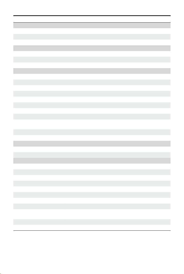
MATRICE 200 Series User Manual
Upward Infrared Sensing System
Obstacle Sensing Range 0-16.4 feet (0-5 m)
FOV ±5°
Operating Environment Large, diffuse and reective obstacles (reectivity >10%)
Charger
Model IN2C180
Voltage 26.1 V
Rated Power 180 W
Battery (TB50-M200)
Name
Model TB50-4280mAh-22.8V
Capacity 4280 mAh
Voltage 22.8 V
Battery Type 6S LiPo
Energy 97.58 Wh
Net Weight 515 g
Operating Temperature -4° to 104° F (-20° to 40° C)
Storage Temperature
Charging Temperature 41° to 104° F (5° to 40° C)
Max Charging Power 180 W
Charging Hub (Model: IN2CH)
Input Voltage 26.1 V
Input Current 6.9 A
Battery (TB55)
Name Intelligent Flight Battery
Model TB55-7660 mAh-22.8V
Capacity 7660 mAh
Voltage 22.8 V
Battery Type 6S LiPo
Energy 176.93 Wh
Net Weight 885 g
Operating Temperature -4° to 104° F (-20° to 40° C)
Storage Temperature
Charging Temperature 41° to 104° F (5° to 40° C)
Max Charging Power 180 W
Intelligent Flight Battery
Less than 3 months: -4° to 113° F (-20° to 45° C)
More than 3 months: 72° to 82° F (22° to 28° C)
Less than 3 months: -4° to 113° F (-20° to 45° C)
More than 3 months: 72° to 82° F (22° to 28° C)
2017 DJI All Rights Reserved.
©
75
Page 76

MATRICE 200 Series User Manual
Aircraft Status Indicator Description
Normal
Red, yellow, green,
blue, and purple ashes
Green Flashes Slowly Safe to Fly (P-mode with GPS and Vision System)
X2 Green Flashes Twice Safe to Fly (P-mode with Vision System but without GPS)
Yellow Flashes Slowly Safe to Fly (A-mode but No GPS and Vision System)
Warning
Fast Yellow Flashing Remote Controller Signal Lost
Slow Red Flashing Low Battery Warning
Fast Red Flashing Critical Low Battery Warning
— Solid Red Critical Error
Green and Yellow Flash
Alternatively
Red Flashing
Alternatively
Red and Yellow Flash
Alternatively
Power on and self-check
Aircraft warming up
IMU Error
Compass Calibration Required
Upgrading the Firmware
Use DJI Assistant 2 or the DJI GO 4 app to upgrade the aircraft and remote controller.
Upgrading the Aircraft Firmware
For the Zenmuse X5S and X4S, the aircraft and gimbal rmware will be updated simultaneously via
DJI Assistant 2 or the DJI GO 4 app.
For the Zenmuse Z30 and XT, only aircraft rmware can be updated via DJI Assistant 2 or the DJI
GO 4 app. Gimbal rmware must be updated via a Micro SD card.
Method 1: Using DJI Assistant 2
1. Power on the Intelligent Flight Battery and toggle the USB Mode Switch left.
2. Connect the aircraft and the PC via the USB cable (with Double A ports).
3. Launch DJI Assistant 2 and login with a DJI account.
4. Click M200SERIES and the rmware update button.
5. Select the rmware version required.
6. DJI Assistant 2 will download and upgrade the rmware automatically.
7. Restart the aircraft after the rmware upgrade is complete.
Method 2: Using the DJI GO 4 App
1. Power on the Intelligent Flight Battery and toggle the USB Mode Switch right.
2. Connect the aircraft and your mobile device via an appropriate USB cable.
3. Follow the on-screen instructions in the DJI GO 4 app to upgrade. Ensure to connect to the Inter-
net when downloading the rmware.
2017 DJI All Rights Reserved.
©
76
Page 77

MATRICE 200 Series User Manual
4. Restart the aircraft after the rmware update is complete.
The rmware update will take around 15 minutes. It is normal that the gimbal will go limp, the
aircraft status indicator blinks abnormally when the aircraft reboots. Wait patiently until the
update is complete.
During an update, the aircraft will sound a quick single beep continuously. The warning
sound will then alternate between a longer beep and a quick double beep once the
update is complete. Restart the aircraft after the rmware update is complete.
If the warning sound turns into a long beep, retry the update.
The battery level should be above 30% for the rmware update process.
When using DJI GO 4 to update, you may disconnect the aircraft and the mobile device
once the update is more than 30% completed. No Internet connection is required.
Upgrading the Remote Controller Firmware
Method 1: Using the DJI GO 4 App
Power on the remote controller and connect it with the DJI GO 4 app. A prompt will appear if a
new rmware upgrade is available. To start upgrading, connect a mobile device to the Internet and
follow the on-screen instructions.
Ensure the battery level is adequate for the remote controller.
Do not disconnect the aircraft from the computer during a rmware upgrade.
Using the Zenmuse XT Gimbal and Camera
The Zenmuse XT Gimbal Adapter is required when mounting the Zenmuse XT gimbal to the Matrice
200 series aircraft. DJI Pilot is required if used with the Zenmuse XT.
1. Attach the Zenmuse XT gimbal adapter onto the Zenmuse XT gimbal.
2017 DJI All Rights Reserved.
©
77
Page 78

MATRICE 200 Series User Manual
2. MounttheZenmuseXTontotheaircraftbysecuringthegimbaladapter.
Mounting the Upward Gimbal and GPS Module
The built-in compass and GPS will fail to work if a single upward gimbal is in use. And the D-RTK
antennas cannot receive the GPS signal when the aircraft is flying under a bridge or other tall
buildings. It is recommended to mount the extended GPS module when a single upward gimbal is
in use in situations like this.
External GPS Module Single Upward Gimbal Connector
Follow the steps below to mount the Upward Gimbal and GPS Module.
Remove the D-RTK antenna
on the left side (facing the
aircraft nose) and mount the
GPS module.
Make sure you secure the GPS module and upward gimbal’s cables with the cable clamps for
Connect the GPS module
to the Extension Port, and
ensure that the side with
the logo faces upward
.
safety.
The GPS module must be installed on the left side when facing the aircraft nose. Note that the
whole aircraft will not retain its IP43 rating if the GPS module is installed.
Single upward gimbal connector and dual downward gimbal connector should be used
separately. DO NOT user them at the same time.
2017 DJI All Rights Reserved.
©
78
Mount the
upward gimbal,
and connect it to
the DGC2.0 port.
Page 79

MATRICE 200 Series User Manual
Dual Downward Gimbals
A dual downward gimbal connector is required to use the M210 or M210 RTK’s dual downward
gimbals.
Mounting the Dual Downward Gimbal Connector
1. Detach the three damping balls. Make sure to carefully pull them from the connector by hand,
not forcefully with tools.
2. Remove the three screws on the top of the single downward gimbal connector.
3. Disconnect the gimbal signal control cable and gimbal video coaxial cable from the single
downward gimbal connector.
2017 DJI All Rights Reserved.
©
79
Page 80
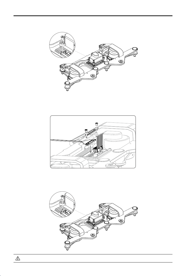
MATRICE 200 Series User Manual
4. Remove the four screws on the top of the dual downward gimbal connector.
5. Connect the gimbal signal control cable and gimbal video coaxial cable to the dual downward
gimbal connector accordingly. Tighten the spring pad with screws to secure the gimbal video
coaxial cable.
6. Tighten the cover onto the dual downward gimbal connector with screws.
Keep the cables neat and orderly to prevent interference from the cover.
2017 DJI All Rights Reserved.
©
80
Page 81
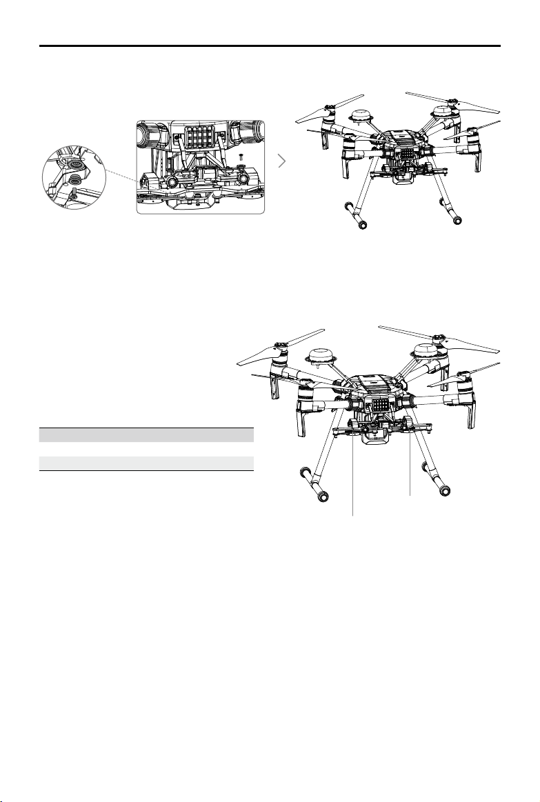
MATRICE 200 Series User Manual
7. Mount the dual downward gimbal connector to the aircraft.
Using the Dual Downward Gimbals
All Zenmuse X5S, X4S, XT, and Z30 gimbals are supported. You can mount them to the Gimbal
Connector I and Gimbal Connector II as shown below:
Gimbal Connector II Gimbal Connector I
Zenmuse XT Zenmuse X4S/X5S/Z30
Zenmuse Z30 Zenmuse X4S/X5S/XT
Gimbal
Gimbal
Connector II
Connector I
Please note that Gimbal Connector II can be mounted with the Zenmuse XT and Z30 only. Gimbal
Connector I and Gimbal Connector II cannot be mounted with two of the same Zenmuse gimbals.
Gimbal Connector I's camera view will show on the main interface in the DJI GO 4 app, while
Gimbal Connector II's camera view will show on the assistant interface. You can switch between
them.
2017 DJI All Rights Reserved.
©
81
Page 82

MATRICE 200 Series User Manual
After-Sales Information
Visit the following pages to learn more about our After-sales Service Policy and warranty information:
1. After-sales Policy: http://www.dji.com/service
2. Refund Policy: http://www.dji.com/service/refund-return
3. Paid Repair Service: http://www.dji.com/service/repair-service
4. Warranty Service: http://www.dji.com/service/warranty-service
2017 DJI All Rights Reserved.
©
82
Page 83

This content is subject to change.
Download the latest version from
http://www.dji.com/matrice-200-series
If you have any questions about this document, please contact DJI by
sending a message to
2017 DJI All Rights Reserved.
©
DocSupport@dji.com
.
 Loading...