

Page 1
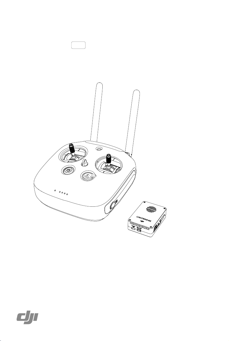
DJI LIGHTBRIDGE 2
User Manual
2015.09
V1.0
Page 2
Searching for Keywords
Search for keywords such as “battery” and “install” to nd a topic. If you are using Adobe
Acrobat Reader to read this document, press Ctrl+F on Windows or Command+F on Mac to
begin a search.
Navigating to a Topic
View a complete list of topics in the table of contents. Click on a topic to navigate to that
section.
Using this Manual
Legends
Warning Important Hints and Tips Reference
Before Flight
The following tutorials and manuals have been produced to ensure you make full use of your
DJI LIGHTBRIDGE 2.
1.
DJI LIGHTBRIDGE 2 In the Box
2.
DJI LIGHTBRIDGE 2 User Manual
Check to see that you have all of the components listed in the DJI LIGHTBRIDGE 2 In the Box
manual. Complete the assembly with the help of this manual and the video tutorial on the DJI
website.
Watch the Video Tutorials
Please watch the tutorial video below to learn how to install the
DJI LIGHTBRIDGE 2 correctly:
http://www.dji.com/product/lightbridge-2/video
Download the DJI GO App
Download and install the DJI GO app before use. Scan the QR code or visit
“http://m.dji.net/djigo” to download the app.
DJI GO supports Android 4.1.2 (or later) or iOS 8.0 (or later).
2015 DJI. All Rights Reserved.
2
©
Page 3

Disclaimer
Thank you for purchasing the DJI Lightbridge 2 (abbreviated as “Lightbridge 2”). Users must
comply with local radio transmission laws and regulations when using this product. By using
this product, you hereby agree to this disclaimer and signify that you understand all points
completely. Please use this product in strict accordance with the manual and be sure to pay
attention to the warnings. When assembling and using this product, follow all instructions
carefully. SZ DJI TECHNOLOGY CO., LTD. and its afliated companies assume no liability for
damage(s) or injuries incurred directly or indirectly from improper use of this product.
DJI is the registered trademark of SZ DJI TECHNOLOGY CO., LTD. (abbreviated as “DJI”).
Names of products, brands, etc., appearing in this manual are trademarks or registered
trademarks of their respective owner companies. This product and manual are copyrighted by
DJI with all rights reserved. No part of this product or manual shall be reproduced in any form
without the prior written consent or authorization of DJI.
This disclaimer is produced in various languages. In the event of divergence among different
versions, the Chinese version shall prevail when the product in question is purchased
in Mainland China, and the English version shall prevail when the product in question is
purchased in any other region.
Caution
Installation
1. Install the Air System antennas before powering on the Lightbridge 2 system.
2. To ensure optimal transmission quality, point the Air System antennas downwards and avoid
obstruction from other onboard equipment.
3. DO NOT twist or bend the Air System antennas.
4. Keep the Air System antennas as far apart as possible to achieve optimal transmission, and
keep the Air System antennas away from metals objects.
5. Only use ofcial DJI antennas for the Air System and Ground System.
6. Connect the HDMI cable to the gimbal camera after gimbal initialization is completed
successfully to avoid damaging the HDMI cable.
7. Keep the HDMI cable away from the onboard GPS module.
8. DO NOT disassemble or modify the Air System or Ground System. Contact DJI or your local
dealer if you have any problems.
9. Maintain an appropriate distance between electronic components to reduce electromagnetic
interference to the minimum.
2015 DJI. All Rights Reserved.
©
3
Page 4

DJI Lightbridge 2 User Manual
Before Use
1. Ensure that all connections are secure and there are no signs of malfunction.
2. Ensure that self-testing is completed successfully when the devices are turned on.
3. Ensure the surrounding area does not have other 2.4GHz transmitting devices that
may cause interference.
4. Ensure that the Ground System battery is above 25% to avoid losing control over the
Air System in mid-flight.
5. Switch your mobile device to Airplane Mode to avoid distractions from incoming calls
or messages.
6. Turn up your mobile device’s volume until you can hear warning alerts from the DJI
GO app clearly.
7. If the video breaks up, adjust the orientation of the Ground System antennas.
8. Ensure your onboard camera is fully charged.
9. Choose anti-EMI (electromagnetic interference) cables or an HDMI monitor for optimal
connection quality.
2015 DJI. All Rights Reserved.
4
©
Page 5

Contents
Using this Manual
Legends
BeforeFlight
WatchtheVideoTutorials
DownloadtheDJIGOApp
Disclaimer
Caution
Installation
BeforeUse
Profile
In the Box
Overview
AirSystem
GroundSystem
Installation
InstallingtheAirSystemonYourAircraft
ConnectingtheGroundSystemtoYourDisplayDevice
StandardConfigurations
2
2
2
2
2
3
3
3
4
7
7
10
10
12
15
15
15
17
Ground System
GroundSystemOperations
DualGroundSystemsMode
LinkingtheGroundSystem
GroundSystemCompliance
19
19
23
24
25
2015 DJI. All Rights Reserved.
©
5
Page 6

DJI GO App
LaunchingDJIGOApp
CameraView
ImageTransmissionSettings
26
26
27
29
Appendix
Specifications
SupportedDJIProducts
SupportedVideoInputs
SupportedVideoOutputs
31
31
32
32
32
2015 DJI. All Rights Reserved.
6
©
Page 7
Prole
DJI Lightbridge 2 is a long range video downlink capable of transmitting 1080p60 full HD video
at distances up to 1.2 miles (2 km). Lightbridge 2 integrates the remote controller module into
the Ground System, which comes with a number of aircraft and gimbal controls as well as some
customizable buttons. Support for multiple Ground Systems allows one operator to control
aircraft movement, while the other operator focuses on video capturing. Real-time video and
ight telemetry can be viewed on your mobile device through the DJI GO app or live broadcast
to an SDI or HDMI display device.
In the Box
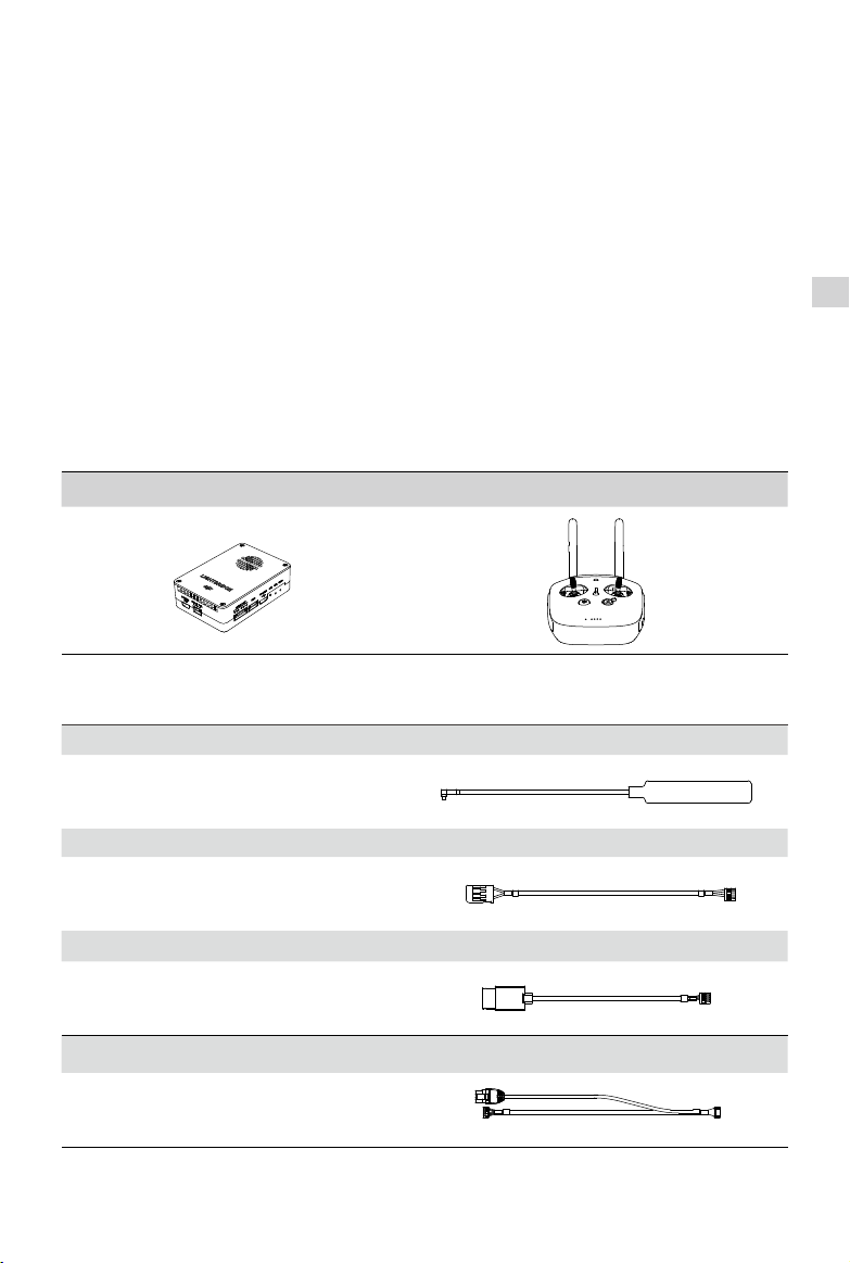
Modules
Air System × 1 Ground System × 1
Air System Components
Prole
Air System Antennas × 2
Transmits the Air System signal to the
Ground System.
DBUS Cable
Connects the Air System to the DJI A2 or
WooKong-M Flight Controller.
DBUS Cable
Connects the Air System to the DJI flight
controller.
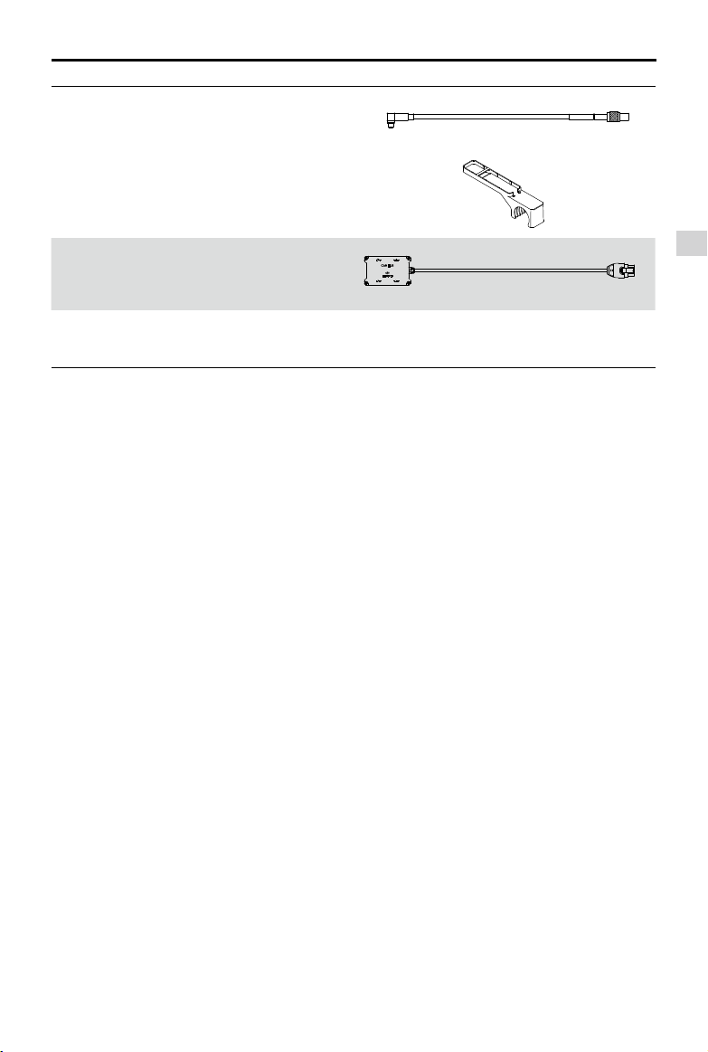
Gimbal Cable × 1
Connects the Air System to the DJI
HD gimbal and DJI ight controller.
I
× 1
II
× 1
2015 DJI. All Rights Reserved.
©
7
Page 8
DJI Lightbridge 2 User Manual
AV Cable × 1
Sends video data from the camera to the
Air System.
HDMI Cable × 1
Sends HD video data from the camera to
the Air System.
Prole
USB Cable × 1
Used to upgrade the Air System rmware
through your PC.
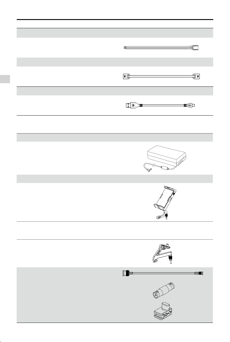
Ground System Components
Battery Charger × 1
Used to charge the Ground System.
Mobile Device Holder × 1
Used to mount your mobile device onto the
Ground System.
Optional Packets(Purchased Separately
Optional Packet 1
Optional Packet 2
2015 DJI. All Rights Reserved.
8
©
HDMI
Screen Holder × 1
SDI Cable × 1
BNC Adapter × 1
Wire Clip × 1
)
Page 9
Optional Packet 3
DJI Lightbridge 2 User Manual
Air System Antenna
Extension Cables × 2
Air System Antenna
Mounts × 2
Optional Packet 4 CAN Hub × 1
Optional Packet 5 Air System Cable Set × 1
Prole
IncludesallAirSystemcomponents.
2015 DJI. All Rights Reserved.
©
9
Page 10
Overview
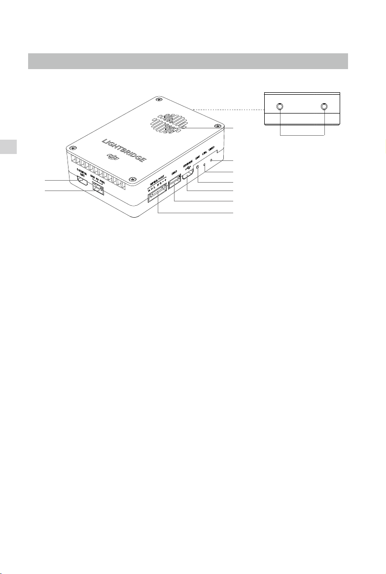
Air System
Overview
[1]
[2]
[1] HDMI IN
Supports up to 1080p60 input resolution.
[2] AV IN
Standard AV input.
[3] Gimbal Port
Connects to both the DJI HD gimbal and DJI ight controller.
a) V+ V-: Receives power from the DJI HD gimbal.
b) L H: Transmits data to the DJI ight controller through the CAN port. (CAN 2 port on the
c) G
[9]
[10]
[8]
[7]
[6]
[5]
[4]
[3]
DJI A2 Flight Controller).
- + : Receives DVSB video input from the DJI HD gimbal.
[4] DBUS Port
Sends the Ground Sytem control signal to the DJI ight controller (X2 port on the DJI A2 or
WooKong-M Flight Controller).
[5] Upgrade Port
Connects to your PC for rmware upgrades through the DJI Lightbridge 2 Assistant.
[6] Link Button
Used to link the Air System with the Ground System.
2015 DJI. All Rights Reserved.
10
©
Page 11

DJI Lightbridge 2 User Manual
[7] Control Indicator
Indicates the status of the Air System and Ground System.
LED Pattern Description
Blinks Red
Link button pressed. Air System is attempting to link with the
Ground System.
Blinks Green Signal detected but not linked to the Ground System.
— Solid Green Successfully linked to the Ground System.
— Solid Red
/
Blinks Yellow and
Green alternately
Video Indicator
[8]
No signal detected. Check the cable connections and ensure the
Ground System is powered on.
Air System and Ground System have different firmware versions.
Ensure you have the latest rmware installed on both devices.
Indicates the video transmission status.
LED Pattern Description
— Solid Green AV/HDMI signal detected.
Blinks Green
AV/HDMI signal detected but transmission failed. Reconnect the Air
System power supply and check the cable connections.
No supported video source is detected. Check that your camera’s
— Solid Red
output format is supported. Refer to the Appendix for a list of
supported video formats.
Overview
[9] Air Vents
Keep clear of obstruction to ensure maximum cooling efciency.
[10] Antenna Port
Used to attach the Air System antennas.
2015 DJI. All Rights Reserved.
©
11
Page 12

DJI Lightbridge 2 User Manual
Ground System
The Ground System uses the same interfaces as the remote controller for the DJI Inspire 1, which
is used as an illustration below. The interfaces marked with an asterisk (*) can be mapped to the
channels of the A2 Flight Controller. Refer to the A2 Flight Controller’s user manual for details.
The remote controller for the Inspire 1 is not compatible with Lightbridge 2. DO NOT
substitute any other remote controller for use with the Lightbridge 2 Ground System.
Overview
[1]
[2]
[9]
[8]
[7]
[3]
[4]
[5]*
[6]
[1] Antennas
Transmits the aircraft’s control and video
signals.
[2] Mobile Device Holder Screw Hole
Used to mount the Mobile Device Holder.
Indicator Pattern Sound Air System Status
— Solid Red chime
Blinks Blue D-D-D
— Solid Green None
— Solid Purple D-D-
— Solid Cyan None
Ground System is set as Master but is not
connected to the Air System.
Ground System is set as Master and is
......
attempting to connect to the Air System.
Ground System is set as Master and is
connected to the Air System
Ground System is set as Slave but is not
connected to the Air System.
Ground System is set as Slave and is
connected to the Air System.
[3] Control Sticks
Controls the aircraft movement.
Customizable in the DJI GO app and
DJI Flight Controller Assistant.
[4] Return-to-Home (RTH) Button
Press and hold to initiate the RTH
procedure.
[5] Transformation Switch*
Customizable switch in the DJI Flight
Controller Assistant.
[6] Battery Level Indicator
Displays the current battery level.
[7] Status Indicator
Indicates the connection status
between the Air System and Ground
System.
2015 DJI. All Rights Reserved.
12
©
Page 13

Blinks Red D-D-D
DJI Lightbridge 2 User Manual
Ground System error, enter DJI GO app for
......
more details.
[8] Power Button
Used to turn on/off the Ground System.
[9] Return-to-Home (RTH) Indicator
Circular LED around the RTH button that
displays the RTH status.
Indicator Pattern Sound Aircraft Status
— Solid White chime Return-to-Home procedure is initiated.
[17] [19]
. . .
.. .. ..
Sending Return-to-Home command to the aircraft.
The aircraft is returning to the Home Point.
[10]*
[11]*
[14] Record Button*
[12]*
Blinks White D
Blinks White DD
[16] [18]
[15]
[14]*
[13]
Customizable button in the DJI Flight
Controller Assistant.
[15] Gimbal Dial
[10] Camera Settings Dial*
Customizable dial in the DJI Flight
Controller Assistant.
[11] Playback Button*
Customizable button in the DJI Flight
Controller Assistant.
[12] Shutter Button*
Customizable button in the DJI Flight
Controller Assistant.
[13] Flight Mode Switch
Switches between P-Mode (Positioning),
A-Mode (Attitude) and F-Mode(Function).
F-Mode can be customized in the DJI
Flight Controller Assistant.
Used to control the pitch of the
gimbal.
[16] Reserved Port
Do not connect any cables to this
Micro USB port.
[17] SDI OUT
Outputs video data to an SDI monitor.
[18] HDMI OUT
Outputs video data to an HDMI
monitor.
[19] USB Port
Connects to your mobile device.
Live HD video and ight telemetry
can be viewed in the DJI GO app.
Overview
2015 DJI. All Rights Reserved.
©
13
Page 14

DJI Lightbridge 2 User Manual
[22]*
[23]
Overview
[20]
[21]*
[20] GPS Module
Pinpoints the position of the Ground System.
[21] C1 Button*
Customizable button in the DJI Flight
Controller Assistant.
[22] C2 Button*
Customizable button in the DJI Flight
Controller Assistant.
[23] Power Port
Used to charge the Ground System’s
internal battery.
2015 DJI. All Rights Reserved.
14
©
Page 15

Installation
Installing the Air System on Your Aircraft
1. Prepare the two Air System antennas and some double-sided foam tape.
2. Insert the antennas into the ports on the side of the Air System and snap into place.
3. Use the foam tape to mount the Air System onto the reserved space of your aircraft
or other suitable at surfaces.
Install the antennas before powering on the Air System.
For optimal transmission quality, point the antennas downwards and avoid
obstruction from other onboard equipment.
Only use ofcial DJI antennas and ensure they are installed correctly.
When connecting the antennas, ensure the connector pin is aligned with the port
hole, and DO NOT apply excessive force to avoid damaging the pin.
Only remove the antennas from the Air System unless it is absolutely necessary.
When removing the antennas, use pliers to grip the metal connector, and DO NOT
apply force to the wire.
For larger aircrafts, use an extension cable to connect the antennas to the Air
System. The DJI Spreading Wings series come with an antenna mount which is
used to position the antennas perpendicular to the landing gear. Watch the video
tutorials on the ofcial DJI website for more details.
Installation
Connecting the Ground System to Your Display Device
Select one of the video ports on the Ground System to output to your display device:
SDI – Connect your SDI monitor to the Ground System using an SDI cable.
HDMI – Connect your HDMI monitor to the Ground System using an HDMI cable.
2015 DJI. All Rights Reserved.
©
15
Page 16

DJI Lightbridge 2 User Manual
USB – Mount your mobile device onto the Mobile Device Holder and connect it to the Ground
System using a USB cable. Launch the DJI GO app to access video and ight telemetry.
The SDI or HDMI cable can be attached to the Ground System handle using the Wire
Clip (optional accessory).
The SDI and HDMI ports on the Ground System cannot be used together.
Below is an illustration using the USB video output. Please prepare a slotted screwdriver.
Install the Mobile Device Holder:
Installation
1. Unfold the Mobile Device Holder . Remove the screw using the slotted screwdriver .
2. Plug the Mobile Device Holder into the Ground System and tighten the Screw Lock.
3. Line up the hole on the Mobile Device Holder with the metal loop on the Ground System.
Insert and tighten the screw.
Mounting Hole
Metal Loop
Screw Lock
Mount Your Display Device:
1. Press the button on the side of the Mobile Device Holder to release the clamp.
2. Place your mobile device inside the clamp and adjust it to secure.
3. Connect your mobile device to the remote controller via a USB cable.
4. Adjust the antennas to the desired position.
2015 DJI. All Rights Reserved.
16
©
Page 17

DJI Lightbridge 2 User Manual
Standard Configurations
This section provides examples and way to congure Lightbridge 2. Choose the conguration
that best ts your needs.
Air System - DJI HD Gimbal + DJI Flight Controller
When used with a DJI HD gimbal, you can select either single or dual video source mode in the
DJI GO app. In single video source mode, the Air System transmits either the gimbal camera
video or FPV camera signal to the Ground System. In dual video source mode, both signals are
transmitted by the Air System.
Connect the system as follows:
1. Connect the gimbal port on the Air System to the G7 port on the DJI HD gimbal and the CAN
BUS port on the ight controller.
2. Connect the HDMI or AV port on the Air System to the FPV camera.
3. Connect the DBUS port on the Air System to the DBUS port (X2 port) on the ight controller with
the DBUS cable.
4. Refer to the user manuals for the gimbal and ight controller for details.
Only use the DJI HD gimbal and DJI ight controller with the latest rmware.
If you are using the DJI A2 Flight Controller, connect the gimbal cable to the CAN 2
port on the controller unit.
Installation
A CAN-HUB is recommended to provide extra CAN ports, if there is not enough CAN port.
Below is an illustration of the DJI HD gimbal connected to the DJI A2 Flight Controller.
DBUS Cable
HD Gimbal
CAN2
2015 DJI. All Rights Reserved.
©
or
FPV Camera
HDMI Cable
AV Cable Gimbal Cable
G7
X2
17
Page 18

DJI Lightbridge 2 User Manual
DJI Lightbridge 2 User Manual
Ground System - Dual Ground Systems Mode
More than one Ground System can connect to the same aircraft in Dual Ground System Mode.
In Dual Ground System Mode, the Master Ground System controls the movement of the aircraft,
while the Slave Ground System controls the movement of the gimbal and camera. When
multiple Slave Ground Systems (max of 3) are connected to the aircraft, only the rst connected
Slave Ground System is able to control the gimbal. The remaining slave Ground System can
view the live feed video from the aircraft, but they cannot control the gimbal.
Installation
Master
Ground System
Slave
Ground System
The gimbal dial on the Master Ground System controls the pitch motion of the camera.
In Dual Ground System Mode, the Slave Ground System can be used to control the roll
and yaw motions of the camera.
2015 DJI. All Rights Reserved.
18
©
Page 19

Ground System
The Ground System features a number of standard interfaces intended for aircraft and camera
control, which are explained below with their most typical functions. However, you can remap
these interfaces to the ight controller channels using the DJI Flight Controller Assistant.
Compliance: The Ground System is compliant with both CE and FCC regulations.
Control Stick Modes: Mode 1, Mode 2, or a customized mode.
Mode 1: The right stick serves as the throttle.
Mode 2: The left stick serves as the throttle.
DO NOT operate more than 3 aircrafts within in the same area (size equivalent to a
soccer eld) to prevent signal interference.
Ground System Operations
Using the Power Button
1. Press the power button once to display the current battery level.
2. Press again and hold to power on the Ground System.
3. The Status Indicator will blink green (blink purple for Slave Ground Systems) rapidly when
the Ground System is linking to the Air System, and become solid green when the link is
established.
4. Press the power button once, again, and hold to power off the Ground System.
Ground System
2015 DJI. All Rights Reserved.
©
19
Page 20

DJI Lightbridge 2 User Manual
Charging the Ground System
Only use the ofcial DJI battery charger to charge the Ground System’s 6000mAh 2S built-in
battery.
Power Outlet
Charger
Ground System
Controlling the Aircraft
The following table describes the functions of the Ground System for the default settings - Mode 2.
Stick Neutral/mid point: Control sticks of the Ground System are placed at the central
position.
Move the Stick: The control stick is pushed away from the central position.
Ground System
(Mode 2)
2015 DJI. All Rights Reserved.
20
©
Aircraft
( indicates nose direction)
Description
Vertical movement of the left stick controls
the aircraft’s elevation. Push up to ascend
and press down to descend.
Use the left stick to take off when the
motors are spinning at idle speed. The
aircraft will hover in place if the stick is in
the neutral position.
Horizontal movement of the left stick
controls the aircraft's heading. Move left
to rotate the aircraft anticlockwise and
move right to rotate the aircraft clockwise.
Page 21

DJI Lightbridge 2 User Manual
Vertical movement of the right stick
controls the aircraft’s pitch. Push up
to y forwards and press down to y
backwards.
Move the stick further for a larger pitch
angle and faster ight.
Horizontal movement of the right stick
controls the aircraft’s roll. Move the stick
left to y left and right to y right.
Move the stick further for a larger roll
angle and faster ight.
Turn the Gimbal Dial to the right to tilt
the camera up, and to the left to tilt the
camera down.
Ground System
Always push the control sticks gently to prevent sudden and unexpected movement
of the aircraft.
The aircraft can be stabilized when the control sticks are at mid point in P-Mode or
A-Mode.
The aircraft cannot stabilize itself automatically in Manual mode, operate with caution.
Flight Modes
Toggle the Flight Mode Switch on the Ground System to one of the three modes.
Figure Flight Mode
P-Mode
P
A
F
A-Mode
F-Mode
P
A
F
2015 DJI. All Rights Reserved.
©
21
Page 22

DJI Lightbridge 2 User Manual
P-Mode (Positioning):
The aircraft uses GPS for positioning. This mode works best when the
GPS signal is strong.
A-Mode (Attitude):
GPS is not used for positioning, and the aircraft only uses its barometer to
maintain altitude. If a GPS signal is present, the aircraft will still return to the last recorded Home
Point if the Ground System signal is lost.
F-Mode (Function):
Acts as A-Mode (default) or Manual Mode for Lightbridge 2. Select the
desired mode in the DJI Flight Controller Assistant.
Return-to-Home (RTH)
Press and hold the RTH Button to bring the aircraft back to the last recorded Home Point.
The LED around the RTH Button will blink white during the RTH procedure. Refer to the ight
Ground System
controller user manual for more information on how to regain control during RTH.
The DJI WooKong-M Flight Controller does not support the RTH feature.
Optimal Transmission Range
To achieve optimal transmission, separate the two antennas and adjust their positions so that
the at side faces the aircraft.
Optimal Transmission RangeStrong Weak
If the transmission signal is weak, adjust the positions of the antennas and fly the aircraft
closer to you.
2015 DJI. All Rights Reserved.
22
©
Page 23

DJI Lightbridge 2 User Manual
Dual Ground Systems Mode
The Dual Ground Systems Mode is disabled by default. To enable this feature, connect your
mobile devices to the desired Master and Slave Ground Systems, launch the DJI GO app and
then following the steps below for each Ground System.
Master Ground System:
1. Go to Camera View >
2. Next to ‘Set RC Status’, select ‘Master’.
3. Enter the connection password.
RC Control Settings
Master and Slave
Set RC Status
to enter RC Settings.
RC Settings
MasterOFF
Slave
Ground System
RC Name Connection Password
Slave RC List
T12254 1234
Slave Ground System:
1. Go to Camera View > to enter RC Settings.
2. Next to ‘Set RC Status’, select ‘Slave’.
RC Settings
RC Control Settings
Master and Slave
Set RC Status
RC Name
Master RC List
T12254
S88642
Request Control
Search for Master Controller
MasterOFF
Slave
2015 DJI. All Rights Reserved.
©
23
Page 24

DJI Lightbridge 2 User Manual
MasterOFF
Slave
主机
从机关闭
主机列表
名称
主从机功能
S88642
遥控器设置
设置遥控器状态
请求控制权
搜索主机
遥控器功能设置
T12254
3. Tap ‘Search for Master Controller’ to register the Master Ground System.
RC Settings
RC Control Settings
Master and Slave
Set RC Status
RC Name
S88642
Request Control
Search for Master Controller
MasterOFF
Slave
Ground System
Master RC List
T12254
4. Select the Master Ground System from the Master RC List and input the connection
password.
The Slave Ground System cannot link to the Air System and control aircraft
movement. To do so, set the Ground System as ‘Master’.
Linking the Ground System
The Ground System is linked to the Air System by default, and linking is only required if a new
Ground System is used for the rst time. Follow these steps to link a new Ground System:
1. Place the Air System and Ground System at roughly 1.5 meters from each other.
2. Turn on the Ground System and connect your mobile device.
3. Launch the DJI GO app, and go to Camera View > > RC Control Settings. Click
‘Linking RC’
.
2015 DJI. All Rights Reserved.
24
©
Page 25

DJI Lightbridge 2 User Manual
RC Control Settings
RC Calibration
Stick Mode
Default stick mode is Mode 2, changing stick modes alters the way the aircraft is controlled.
Do not change unless familiar with your new mode.
Linking RC
4. The Ground System Status Indicator will blink blue and emit a beep sound when the Ground
System is ready to link.
RC Control Settings
RC Calibration
Stick Mode
Default stick mode is Mode 2, changing stick modes alters the way the aircraft is controlled.
Do not change unless familiar with your new mode.
Searching for aircraft frequency,
timeout in 54 seconds
Press the linking button on the air
system to link this remote controller
Cancel
Linking RC
C2
C2
5. Press the Link Button on the Air System to begin linking. The Ground System Status Indicator
will glow solid green if linking is successful.
The linked Ground System will disconnect from the Air System if another Master Ground
System attempts to link to the same Air System.
Ground System
Ground System Compliance
The Ground System is compliant with the CE and FCC standards.
2015 DJI. All Rights Reserved.
©
25
Page 26

DJI GO App
DJI GO is an essential hub to operate your DJI equipment, share your artwork, explore the
community, and manage your DJI account, all at once. Use DJI GO app with Lightbridge 2 to
select channel, change the video output device and congure the transmission settings. It is
recommended that you use a tablet for the best experience.
iPad
LIGHTBRIDGE 2
80%
DJI GO App
Aircraft connected
Enter Camera View
Equipment Library Explore Me
Launching DJI GO App
1. Power on the Ground System and then the Air System. The Status Indicator on the Ground
System will glow solid green (solid cyan for Slave Ground System).
2. The Control Indicator and the Video Indicator on the Air System will glow solid green if the Air
System and Ground System are communicating normally.
3. Launch the DJI GO app on your mobile device. You will see a live video feed after you enter
Camera View if the Lightbridge 2 system is working normally.
4. Real-time ight telemetry will be displayed if the ight controller is working normally.
Position the Air System antennas downwards and the Ground System antennas
upwards. Ensure that the antennas are not obstructed by other onboard devices.
2015 DJI. All Rights Reserved.
26
©
Page 27

DJI Lightbridge 2 User Manual
Camera View
On the Equipment page, you can enter Camera View, operate Lightbridge 2 settings or view
your ight records. The screen contains a live HD video feed from the camera.
[6][5][4][3][2][1]
[10]
[9]
P-GPS
H:
39MD:210M
H.S:
14.2 M/S
[1] Flight Mode
The current ight mode is displayed next to this icon.
:
[2] GPS Signal Strength
Shows the current GPS signal strength. Green bars indicate an adequate signal.
:
Safe to Fly (GPS)
V.S:
4.5 M/S
[8]
[7]
DJI GO App
222M
[3] System Status Bar
Indicates the current aircraft system status and displays warning messages.
:
[4] Ground System Signal
Shows the signal strength of the Ground System. Tap to bring up the Remote
:
Controller settings.
2015 DJI. All Rights Reserved.
©
27
Page 28

DJI Lightbridge 2 User Manual
[5] Video Downlink Signal
Shows the signal strength of the video downlink between the Air System and Ground
:
System. Tap to enter Image Transmission Settings.
[6] Battery Level
Shows the current battery level.
:
[7] General Settings
Tap to view settings for the unit of measurement, ight route display and live streaming.
:
[8] Flight Telemetry
DJI GO App
H:
39MD:210M
H.S:
14.2 M/S
V.S:
4.5 M/S
222M
Flight Attitude and Radar Function
The aircraft’s ight attitude is indicated by the target-like icon.
(1) The red arrow indicates the aircraft’s heading.
(2) The ratio between the blue and gray areas indicates the aircraft’s pitch.
(3) The horizontal level of the blue-gray boundary indicates the aircraft's roll angle.
Flight Parameters
Height: Vertical distance from the Home Point.
Distance: Horizontal distance from the Home Point.
Vertical Speed: Movement speed across a vertical distance.
Horizontal Speed: Movement speed across a horizontal distance.
Aircraft Distance
The horizontal distance between the aircraft and the operator.
[9] Gimbal Operation Mode
Tap to switch between Gimbal Operation Modes.
:
[10] Back
Tap to return to the main menu.
:
2015 DJI. All Rights Reserved.
28
©
Page 29

DJI Lightbridge 2 User Manual
Image Transmission Settings
13
-100
-90
-80
-70
-60
Channel
Auto
Current Channel
Unstable Quality
Stable Quality
14 15 16 17 18 19 20
Channel 15
Channel
Signal Diagnostics
Image Transmission Quality
10Mbps(0.7km)
Custom
Output Format
Output Port
Output Mode
OSD Settings
Picture-in-Picture for HDMI/SDI
PIP_LB
HDMI SDI
1080P 60
High Quality Mode
Transmission Mode
Low Latency Mode
Image Transmission Settings
Go to the Camera View, and tap to enter the Lightbridge 2 image transmission settings
window.
DJI GO App
[1] Channel
The interference levels for different channel are shown in the bar chart. Auto and Custom
mode are available.
Auto (default): The channel with the best transmission is automatically selected from eight
channels, and the Image Transmission Quality is automatically adjust with signal bandwidth.
Custom: Manually select the channel and image transmission quality from 8 channels. A
larger bandwidth will allow better image quality.
The channel signal can vary in mid-ight. Use this function cautiously.
2015 DJI. All Rights Reserved.
©
29
Page 30

DJI Lightbridge 2 User Manual
[2] Transmission Mode
Low Latency Mode: Optimized for smooth transmission, the channel latency is about 50ms
in interference-free environments.
High Quality Mode: Optimized for high quality transmission.
[3] Output Port
Select HDMI or SDI as your output device.
[4] Output Mode
Select different video sources to display:
LB:Displays the HDMI or AV output of the FPV camera.
DJI GO App
EXT:Displays the video from the HD Gimbal.
PIP_LB:Displays the video from HD Gimbal camera as the main subject, and the HDMI
or AV video from FPV camera in a mini window.
PIP_EXT:Displays the HDMI or AV output of the FPV camera as the main subject, and the
video from the HD Gimbal in a mini window.
[5] Output Format
Select the video output format.
[6] OSD Settings
Enable OSD or change the display margins on your HDMI or SDI device.
[7] Picture-in-Picture for HDMI/SDI
Set the position of PIP on your HDMI or SDI device.
[8] Signal Diagnostics
Run signal diagnostics to test for an antenna malfunction.
2015 DJI. All Rights Reserved.
30
©
Page 31

Appendix
Specifications
General
Max Transmission Distance
(outdoors and unobstructed)
EIRP 100 mW @2.4 GHz
Operating Frequency
Air System
Dimensions (excluding antennas) 68 mm × 48 mm × 21 mm (L-W-H)
Weight (excluding antennas) 70 g
Antenna Gain 2 dBi @2450 MHz
Operating Voltage 9-12 V
Operating Current 650 mA @12 V
Operating Temperature 14° to 104° F (-10° to 40° C)
Antenna Connector MMCX Male
Ground System
Dimensions 182 mm × 167 mm × 104 mm (L-W-H)
Weight 810 g
Antenna Gain 3.5 dBi @2450 MHz
Built-in Battery 7.4 V, 6000 mAh
Operating Current 900 mA
Operating Temperature 14° to 104° F (-10° to 40° C)
Charging Temperature 32° to 104° F (0° to 40° C)
Video Output Port HDMI, SDI, USB
Battery Charger
Output Voltage 17.4 V
Rated Power 57 W
1.2 miles (2 km)
920.6 MHz to 928 MHz (Japan)
5.725 GHz to 5.825 GHz
2.400 GHz to 2.483 GHz
Appendix
2015 DJI. All Rights Reserved.
©
31
Page 32

DJI Lightbridge 2 User Manual
Supported DJI Products
Only use these products with the latest rmware.
HD Gimbals Z15-GH4, Z15-5D III, Z15-A7, Z15-BMPCC
Flight Control Systems A2, WooKong-M
Flying Platforms S1000+, S1000, S900, S800 EVO, F550, F450
Supported Video Inputs
Source Video Formats
AV PAL25, NTSC30
HDMI 720p50, 720p60, 1080i50, 1080i60, 1080p25, 1080p30, 1080p50, 1080p60
Appendix
Supported Video Outputs
Source Video Formats
HDMI 720p50, 720p60, 1080i50, 1080i60, 1080p24, 1080p30, 1080p50, 1080p60
SDI 720p50, 720p60, 1080i50, 1080i60, 1080p24, 1080p30, 1080p50, 1080p60
2015 DJI. All Rights Reserved.
32
©
Page 33

This content is subject to change.
Download the latest version from
http://www.dji.com/product/lightbridge-2
If you have any questions about this document, please contact DJI by
sending a message to
2015 DJI. All Rights Reserved.
©
DocSupport@dji.com
.
 Loading...