

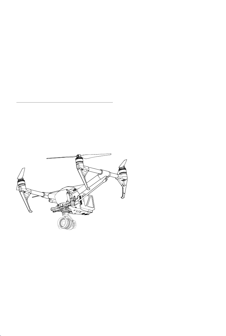
Page 1

INSPIRE 2
User Manual
2016.12
V1.0
Page 2

Searching for Keywords
Search for keywords such as “battery” and “install” to find a topic. If you are using Adobe
Acrobat Reader to read this document, press Ctrl+F on Windows or Command+F on Mac to
begin a search.
Navigating to a Topic
View a complete list of topics in the table of contents. Click on a topic to navigate to that
section.
Printing this Document
This document supports high resolution printing.
Using this manual
Legends
Warning Important Hints and Tips Reference
Before Flight
The following tutorials and manuals have been produced to ensure you to make full use of your
Inspire 2.
1. In the Box
2. Safety Guidelines and Disclaimer
3. Quick Start Guide
4. Intelligent Flight Battery Safety Guidelines
5. User Manual
Watching all the tutorial videos and reading the Disclaimer before flight is recommended.
Afterwards, prepare for your rst ight by using the Quick Start Guide. Refer to this manual for more
comprehensive information.
Watch the video tutorials
Please watch the tutorial video below to learn how to use Inspire 2 correctly and safely:
http://www.dji.com/inspire-2/info#video
Download the DJI GOTM 4 app
Download and install the DJI GO 4 app before use. Scan the QR code or visit
“https://m.dji.net/djigo4” to download the app.
For the best experience, use mobile device with Android V 4.4 or above. Requires iOS 9.0 or later.
Download the DJI ASSISTANTTM 2
http://www.dji.com/inspire-2/info#downloads
2016 DJI. All Rights Reserved.
2
©
Page 3

Contents
Using this manual
Legends 2
Before Flight 2
Watch the video tutorials 2
Download the DJI GO 4 app 2
Download the DJI ASSISTANT 2 2
Product Prole
Introduction 6
Feature Highlights 6
Assemble the Aircraft 6
Preparing Remote Controller 8
Aircraft Diagram 9
Remote Controller Diagram 10
Aircraft
Flight Controller 13
Flight Mode 13
Flight Status Indicator 14
Return-to-Home (RTH) 15
TapFly 19
ActiveTrack 21
Tripod Mode 23
Spotlight Pro 23
Vision System and Infrared Sensing System 23
Flight Recorder 27
Attaching and Detaching the Propellers 27
DJI Intelligent Flight Battery 27
12
2
5
Remote Controllers
RemoteControllerProle 34
Remote Controller Operations 34
Dual Remote Controllers Mode 39
Remote Controller Status LED 42
Linking the Remote Controller 42
Used with the DJI Focus 44
Updating the Home Point 44
2016 DJI. All Rights Reserved.
©
33
3
Page 4

INSPIRE 2 User Manual
Gimbal and Camera
Camera 48
Gimbal 49
Using CINESSD 51
DJI GO 4 App
Camera 54
Editor 57
SkyPixel 57
Me 57
Flight
Flight Environment Requirements 59
Flight Limits and No-Fly Zones 59
PreightChecklist 62
Calibrating the Compass 63
Auto Take-off and Auto Landing 64
Starting/Stopping the Motors 64
StoptheMotorMid-ight 65
Flight Test 65
Appendix
Specications 68
Upgrading the Firmware 72
Compliance Information 74
After-Sales Information 76
47
53
58
65
2016 DJI. All Rights Reserved.
4
©
Page 5

Product Prole
This chapter describes the features of
Inspire 2, instructs you to assemble the
aircraft and explains the components on
the aircraft and remote controllers.
2016 DJI. All Rights Reserved.
©
5
Page 6

Product Prole
Introduction
The Inspire 2 is a powerful aerial film making system with class leading agility and speed,
redundancy features for maximum reliability, and new, smart features that make capturing complex
shots easy. The camera unit is now independent from image processor so that you have the
exibility to choose the perfect gimbal and camera system for each of your scenes. Dual frequency
support in the remote controller makes the HD video downlink more efcient and more stable.
Feature Highlights
Upgraded TapyTM and ActiveTrackTM commands in the DJI GO 4 app, the Inspire 2 ies anywhere
visible on-screen with a tap and tracks moving subjects effortlessly.
Flight Controller: The flight controller has been updated to provide a safer, more reliable flight
experience. A new ight recorder stores critical data from each ight. A system of visual sensors
enhance hovering precision when ying indoors or in environments where GPS is unavailable. Dual
IMUs and compasses design provides redundancy.
HD Video Downlink: The low-latency long range (up to 4.3mi (7km)) HD downlink is powered by an
en hanced version of DJI LIGHTBRIDGETM. Support of 2.4 GHz and 5.8 GHz ensures a more reliable
con nection in environments with more interference.
Camera and Gimbal: The camera unit is now independent from image processor so that you
have the exibility to choose the perfect gimbal and camera system for each of your scenes. This
means that regardless of which camera you choose, you have the same powerful processing
backing it, and when using the Zenmuse X5S, the ability to capture RAW videos. Lossless video (in
CinemaDNG and ProRes format), and DNG RAW photo burst shooting will be available when DJI
CINESSD used.
Intelligent Flight Battery: The new DJI Intelligent Flight Battery features upgraded battery cells and
an advanced power management system to provide up to 25 minutes of ight with Zenmuse X5S
and 27 minutes with Zenmuse X4S.
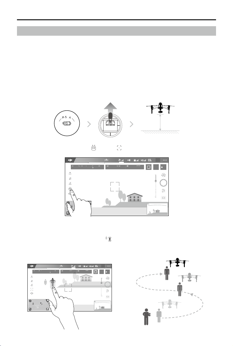
Assemble the Aircraft
Unlocking Travel Mode
The aircraft is in Travel Mode during delivery. Follow these steps to change it to Landing Mode
before your rst ight:
1. Insert the battery pair.
2. Press the power button a minimum of ve times.
3. Unfold the landing gear to Landing Mode and power on automatically.
2016 DJI. All Rights Reserved.
6
©
Page 7

INSPIRE 2 User Manual
5 x
Insert the battery
pair
Press the power button
a minimum of ve times
Unfold the landing gear to Landing
Mode and power on
Mounting the Zenmuse X5S to the
aircraft (Powering off not required)
Battery must be fully charged before using it for the first time. Refer to "Charging the
Intelligent Flight Battery" for more information .
The aircraft cannot change to Landing Mode from Travel Mode with the gimbal camera
attached.
Place the aircraft on the smooth and reective surface (e.g. table or tile) before switching between
the travel modes to the landing mode.
Keep your hands away from the transformation mechanism when unfolding the landing gear.
Make sure to press the battery remove button when removing the battery.
Please follow the steps to enter Travel Mode: Power off the aircraft and then detach the
gimbal and propellers. Continuously press the power button for at least 5 times to change
the aircraft into Travel Mode. Then press the Battery Remove Button to remove the
batteries.
Mounting the Zenmuse X5S to the Inspire 2
1. Remove the Gimbal Cap from the Zenmuse X5S.
2. Press the gimbal and camera release button on the Inspire 2. Rotate to remove the Gimbal Cap
from the Inspire 2.
3. Align the white dot on the gimbal to the red dot on Inspire 2 and insert the gimbal.
4. Rotate the Gimbal Lock to the locked position by aligning the red dots.
11
2
3
4
Always ensure that the DJI Gimbal Connector 2.0 on the Inspire 2 is in the right position
when mounting, otherwise the camera will not mount.
Remove the lens cap when the Zenmuse X5S is in use.
Always power off the aircraft before removing the gimbal camera.
2016 DJI. All Rights Reserved.
©
7
Page 8

INSPIRE 2 User Manual
Attaching 1550T Quick Release Propellers
Following the steps below to attach the 1550T quick release propellers.
1. Pair the propellers and motors with arrows of the same color (red or white).
1
Press down the spring pad and rotate
the propeller lock until the arrows are
aligned and you hear a click.
Attach the propeller
onto the motor.
2
Again, rotate the propeller lock
until you hear a click.
3
Make sure to press down the spring pad before rotating the propeller lock.
Preparing Remote Controller
Tilt the Mobile Device Holder to the desired position then adjust the antenna as shown.
1. Press the button on the side of the Mobile Device Holder to release the clamp, adjust it to t then
attach your mobile device.
2. Connect your mobile device to the remote controller with a USB cable.
3. Plug one end of the cable into your mobile device, and the other end into the USB port on the
back of the remote controller.
2
1
2016 DJI. All Rights Reserved.
8
©
3
Page 9

Aircraft Diagram
INSPIRE 2 User Manual
10
9
11
8
7
1
2
12
6
19
2
0
21
5
13
14
4
3
15
16
17
18
[1] FPV Camera
[2] Forward Vision System
[3] DJITM Gimbal Connector V2.0 (DGC2.0)
[4] Gimbal and Camera Detach Button
[5] Downward Vision System
[6] Extended Device Maounting Position
[7] Transformation Mechanism
[8] Control and Processing Center
(with Micro SD Card Slot)
[9] Front LEDs
[10] Propulsion System (with Motors, Propellers, etc.)
[11] Rear LEDs
[12] Intelligent Flight Batteries
[13] Power Button
[14] Battery Level Indicators
[15] Battery Remove Button
[16] Upward Infrared Sensor
[17] Aircraft Status Indicator
[18] DJI CINESSDTM Slot
[19] Linking Button
[20] USB Mode Switch
[21] USB Port
2016 DJI. All Rights Reserved.
©
9
Page 10

INSPIRE 2 User Manual
Remote Controller Diagram
[1] Power Button
Used to turn the Remote Controller on and
off.
[2] Transformation Switch
Toggle the switch up or down to raise or
lower the landing gear during ight.
[3] Return-to-Home (RTH) Button
Press and hold the button to initiate Return
to Home (RTH).
[4] Control Sticks
Controls the orientation and movement of
the aircraft.
[5] Status LED
Displays the Remote Controller's system
status.
[6] Battery Level LEDs
Displays the battery level of the Remote
Controller.
[7] Power Port
Connect to the Charger to charge the battery
of the remote controller.
[8] Mobile Device Holder
Securely mounts your mobile device to the
remote controller.
[9] Antennas
Relays aircraft control and video signal.
[10] Handle Bar
8
9
1
5
2
3
4
10
6
7
17 18 19
11
14
13
20
2221
12
1615
[11] Control Dial (Gimbal/FPV)
Use this dial to control the tilt of the gimbal. In gimbal’s free mode, press and hold on the C1
Button and rotate the control dial, to adjust the yaw of the gimbal. To adjust the tilt of the FPV
camera, press and hold on the C2 Button and rotate the control dial.
[12] Camera Settings Dial
Turn the dial to adjust camera settings. (Only functions when the remote controller is connected
to a mobile device running the DJI GO 4 app.)
[13] Record Button
Press to start recording video. Press again to stop recording.
[14] Flight Mode Switch
Switch between P-mode, S-mode, and A-mode.
2016 DJI. All Rights Reserved.
10
©
Page 11

INSPIRE 2 User Manual
[15] Shutter Button
Two-stage button, press to take a photo.
[16] Pause Button
Press once to allow the aircraft to exit from TapFly, ActiveTrack and Advanced mode.
[17] Micro USB Port
Use this port to upgrade the rmware.
[18] CAN Bus
Reserved extended port.
[19] HDMI A Port
HDMI A Port is for video output.
[20] USB Port
Connection to mobile device for DJI GO 4 app.
[21] C1 Button
Customizable through the DJI GO 4 app.
[22] C2 Button
Customizable through the DJI GO 4 app.
2016 DJI. All Rights Reserved.
©
11
Page 12
Aircraft
This chapter describes the features of
the Flight Controller, Vision System and
the Intelligent Flight Battery.
Page 13

Aircraft
Flight Controller
The Inspire 2 ight controller features several important upgrades. Safety modes include Failsafe
and Return-to-Home. These features ensure the safe return of your aircraft if the control signal is
lost. The ight controller can also save critical ight data from each ight to the on-board storage
device. The new ight controller also provides increased stability and a new air braking feature.
Flight Mode
Three ight modes are available. The details of each ight mode are found in the section below:
P-mode (Positioning) :
P-mode works best when the GPS signal is strong. The aircraft utilizes the GPS and Forward
and Downward Vision Systems to locate itself, automatically stabilize, and navigate between
obstacles. Advanced features such as TapFly and ActiveTrack are enabled in this mode.
When the Forward Vision System is enabled and lighting conditions are sufcient, the maximum
ight attitude angle is 25°. When forward obstacle sensing are disabled, the maximum ight
attitude angle is 35°.
When the GPS signal is weak and lighting conditions are too dark for the Forward and
Downward Vision Systems, the aircraft will only use its barometer for positioning to control
altitude.
Note: P-mode requires larger stick movements to achieve high speeds.
S-mode (Sport):
The aircraft is using GPS for positioning. As Forward and Downward Vision Systems are
disabled, the aircraft will not be able to sense and avoid obstacles when in Sport Mode. Ground
Station and the Intelligent Flight functions are also not available in Sport Mode.
Note: Aircraft responses are optimized for agility and speed making it more responsive to stick
movements.
A-mode (Attitude):
When neither the GPS nor the Vision System is available, the aircraft will only use its barometer
for positioning to control the altitude.
The forward Vision System is disabled in S-mode (Sport), which means the aircraft will
not be able to automatically avoid obstacles in its ight path. Be vigilant and stay clear
of nearby obstacles.
The aircraft’s maximum speed and braking distance are signicantly increased in S-mode
(Sport). A minimum braking distance of 164 feet (50 meters) is required in windless
conditions.
The aircraft’s responsiveness is signicantly increased in S-mode (Sport), which means a small
stick movement on the remote controller will translate into a large travel distance of the aircraft.
Be vigilant and maintain adequate maneuvering space during ight.
The aircraft’s descent speed is signicantly increased in S-mode (Sport). A minimum braking
distance of 164 feet (50 meters) is required in windless conditions.
Use the Flight Controller mode switch to change the ight mode of the aircraft.
2016 DJI. All Rights Reserved.
©
13
Page 14
INSPIRE 2 User Manual
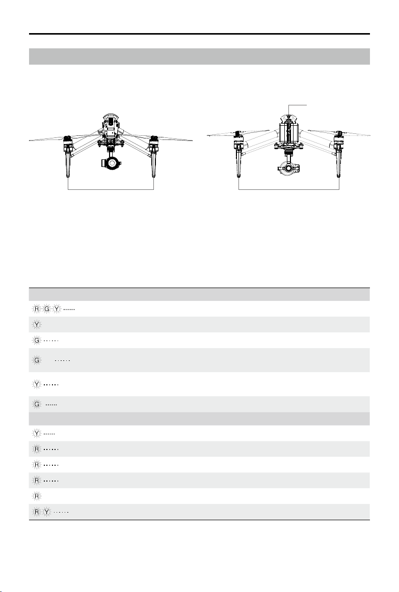
Flight Status Indicator
The Inspire 2 comes with the Front LED, Rear LED and Aircraft Status Indicator. The positions of
these LEDs are shown in the gure below:
Aircraft Status Indicator
Rear LEDFront LED
The Front LEDs show the orientation of the aircraft. The Front LEDs glow solid red when the aircraft
is turned on to indicate the front (or nose) of the aircraft (the Front and rear LEDs can be turned
off in the DJI GO 4 app). The Aircraft Status Indicator communicates the system status of the ight
controller. Refer to the table below for more information about the Aircraft Status Indicator.
Aircraft Status Indicator Description
Normal
Alternating red, green and yellow ashes Turning On and Self Diagnostic Testing
×4 Four yellow ashes Warming Up
Slow green ashing P-mode with GPS*
×2 Two green ashes
Slow yellow ashing
Fast green ashing Braking
Warning
Fast yellow ashing Remote Controller Signal Lost
Slow red ashing Low Battery Warning
Fast red ashing Critical Low Battery Warning
Red ashing IMU Error
— Solid Red Critical Error
Fast alternating red and yellow ashing Compass Calibration Required
P-mode with Forward and Downward
Vision Systems*
No GPS and Forward and Downward
Vision Systems
* Green ashes slowly in P-mode and ashes quickly in S-mode.
2016 DJI. All Rights Reserved.
14
©
Page 15

INSPIRE 2 User Manual
Return-to-Home (RTH)
Return-to-Home (RTH) function brings the aircraft back to the last recorded Home Point. There are
three types of RTH: Smart RTH, Low Battery RTH, and Failsafe RTH. This section describes these
three scenarios in detail.
GPS
If a strong GPS signal was acquired before takeoff, the Home Point is
Home Point
the location from which the aircraft launched. The GPS signal strength
is indicated by the GPS icon ( displays with at least four bars). The
aircraft status indicator will blink rapidly when the home point is recorded.
The aircraft can sense and avoid obstacles when the Forward Vision System is enabled and
lighting conditions are sufcient. The aircraft will automatically climb up to avoid obstacles and
descend slowly as it returns to the home point. To ensure the aircraft returns home forwards, it
cannot rotate or y left and right during RTH while the Forward Vision System is enabled.
Failsafe RTH
The Forward Vision System allows the aircraft to create a real-time map of its ight route as it ies. If
the Home Point was successfully recorded and the compass is functioning normally, Failsafe RTH
will be automatically activated if the remote controller signal is lost for more than three seconds. The
aircraft will plan its return route and retrace its original ight route home. The aircraft will hover for
10 seconds at its current location. When it regains signal connection it will wait for pilot commands.
The Return-to-Home process may be interrupted and the pilot given control of the aircraft if the
remote controller signal connection is re-established.
Description
Failsafe Illustration
1 Record Home Point
Blinking Green
4
Signal Lost Lasts (after 3 sec.)
Fast Blinking Yellow
2 Conrming Home Point
Blinking Green
5
RTH (adjustable altitude)
Height over HP>Failsafe Altitude
Elevate to Failsafe Altitude
Failsafe Altitude
Fast Blinking Yellow
Height over HP<=Failsafe Altitude
3 Remote Controller Signal Lost
Fast Blinking Yellow
6 Landing (af ter hovering for 5 secs)
Fast Blinking Yellow
Aircraft cannot return to the Home Point when GPS signal is weak ( [ ] displays less
than four bars) or unavailable.
Aircraft automatically descends and lands if RTH is triggered when the aircraft ies within a
65 feet (20 meters) radius of the Home Point. Aircraft will stop ascending and immediately
return to the Home Point if you move the left stick if the aircraft reaches 65 feet (20 meters)
altitudes or beyond during Failsafe.
The aircraft cannot avoid obstruction during Failsafe RTH if Forward Vision System is
disabled. It is important to set a suitable Failsafe altitude before each ight. Launch the DJI
GO 4 app, enter “Camera” and tap to set the Failsafe Altitude.
User cannot control the aircraft while the aircraft is ascending to 65 feet (20 meters) from the
current altitude. However, user can press RTH button once to exit ascending and regain control.
2016 DJI. All Rights Reserved.
©
15
Page 16

INSPIRE 2 User Manual
Smart RTH
Use the RTH button on the remote controller or tap the RTH button in the DJI GO 4 app and
follow the on-screen instructions when GPS is available to initiate Smart RTH. The aircraft will
then automatically return to the last recorded Home Point. Use the remote controller to control the
aircraft’s speed or altitude to avoid a collision during the Smart RTH process. As the aircraft returns,
it will use the primary camera to identify obstacles as far as 300m in front, allowing it to plan a safe
route home. Press and hold the Smart RTH button once to start the process, and press the Smart
RTH button again to terminate the procedure and regain full control of the aircraft.
Low Battery RTH (Can be turned off in DJI GO 4 app)
The low battery level failsafe is triggered when the DJI Intelligent Flight Battery is depleted to a point
that may affect the safe return of the aircraft. Users are advised to return home or land the aircraft
immediately when prompted. The DJI GO 4 app will display a notice when a low battery warning
is triggered. The aircraft will automatically return to the Home Point if no action is taken after a tensecond countdown. The user can cancel the RTH procedure by pressing the RTH button on the
remote controller. The thresholds for these warnings are automatically determined based on the
aircraft’s current altitude and distance from the Home Point.
The aircraft will land automatically if the current battery level can only support the aircraft long
enough to descend from its current altitude. The user can still use the remote controller to alter the
aircraft’s orientation during the landing process.
The Battery Level Indicator is displayed in the DJI GO 4 app, and is described below:
Battery
Level
Warning
Low battery
level
warning
2016 DJI. All Rights Reserved.
16
©
Critical Low battery level
warning (Red)
Remark
Battery power
is low. Land
the aircraft.
Low battery
level warning (Yellow)
H
Power requires
to return home
Battery level Indicator
Aircraft Status
Indicator
Aircraft status
indicator blinks
RED slowly.
Sufcient battery
level (Green)
Remaining ight time
12:29
DJI GO 4 App
Tap “Go-home” to have the
aircraft return to the Home
point and land automatically,
or “Cancel” to resume normal
flight. If no action is taken,
the aircraft will automatically
go home and land after 10
seconds. Remote controller
will sound an alarm.
Flight
Instructions
Fly the aircraft
back and land
it as soon as
possible, then
stop the motors
and replace the
battery.
Page 17
INSPIRE 2 User Manual
20 m
H
The DJI GO 4 app display
Critical Low
battery level
warning
The aircraft
must land
immediately.
Aircraft status
indicator blinks
RED quickly.
will ash red and the aircraft
will start to descend. The
remote controller will sound
an alarm.
Estimated
remaining
ight time
Estimated
remaining ight
based on current
battery level.
N/A N/A N/A
When the Critical low battery level warning is triggered and the aircraft begins to land
automatically, push the left stick upward to make the aircraft hover at its current altitude,
giving you an opportunity to navigate to a more appropriate landing location.
The colored zones and markers on the battery level indicator bar reect the estimated
remaining ight time. They are automatically adjusted according to the aircraft’s current
location and status.
Failsafe Safety Notices
The aircraft cannot avoid obstruction during the Failsafe RTH when
the Forward Vision System is disabled. Therefore, it is important to set
a suitable Failsafe altitude before each ight. Launch the DJI GO 4
app, enter “Camera” and tap to set the Failsafe Altitude.
If the aircraft is ying under 65 feet (20 meters) and Failsafe (including
20 m
Smart RTH, Lower Battery RTH ) is triggered, the aircraft will first
automatically ascend to 65 feet (20 meters) from the current altitude.
You can only cancel the ascending by exiting the Failsafe.
Allow the aircraft
to descend
and land
automatically.
20 m
H
Aircraft automatically descends and lands if RTH is triggered when
the aircraft ies within a 65 feet (20 meters) radius of the Home Point.
Aircraft will stop ascending and immediately return to the Home Point
if you move the left stick if the aircraft reaches 65 feet (20 meters)
altitudes or beyond during Failsafe.
Aircraft cannot return to the Home Point when GPS signal is weak
( [
] displays less than four bars) or unavailable.
if you move the left stick after the aircraft rises above 65 feet (20
meters) but below the pre-set Failsafe RTH altitude, the aircraft will
stop ascending and immediately return to the Home Point.
2016 DJI. All Rights Reserved.
©
17
Page 18

INSPIRE 2 User Manual
Obstacle Avoidance During RTH*
Aircraft can now sense and actively attempt to avoid obstacles during RTH, provided that the
lighting conditions are adequate for the Forward Vision System. Upon detecting an obstacle, the
aircraft will act as follows:
1. The aircraft will use the primary camera to identify obstacles as far as 984 feet (300 meters) in
front, allowing it to plan a safe route home.
2. The aircraft decelerates when an obstacle is sensed at 49 feet (15 meters) ahead.
3.The aircraft stops and hover then start ascending vertically to avoid the obstacle. Eventually, the
aircraft will stop climbing when it is at least 16 feet (5 meters) above the detected obstacle.
4. Failsafe RTH procedure resume, the aircraft will continue ying to the Home Point at the current altitude.
5 meters
300 meters
15 meters
*Coming soon.
The Obstacle Sensing function is disabled during RTH descent. Proceed with care.
To ensure the aircraft returns home forwards, it cannot rotate during RTH while the For-
ward Vision System is enabled.
The aircraft cannot avoid obstacles , beside, or behind the aircraft.
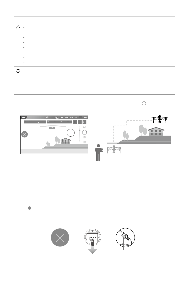
Landing Protection Function
Landing Protection will activate during auto landing.
1. When Landing Protection determines that the ground is suitable for landing, the Inspire 2 will land gently.
2. If Landing Protection determines that the ground is not suitable for landing, the Inspire 2 will hover
and wait for pilot conrmation. The aircraft will hover if it detects the ground is not appropriate for
landing even when critically low battery warning appears. Only when the battery level decreases to 0%
will the aircraft starts landing. The user can still control the aircraft’s ight orientation.
3. If Landing Protection is not operational, the DJI GO 4 app will display a landing prompt when
the Inspire 2 descends below 0.7 meters. Tap to conrm or pull down the stick for 2s to activate
landing once ensure the environment is appropriate for landing.
The aircraft will not detect the landing ground with the landing protection function on in the
following circumstances:
When the user is controlling the pitch/roll/throttle sticks (Landing ground detection will be
re-activated once the sticks is not in use)
When the positioning system is not properly working (e.g. drift position error)
When the downward vision system is calibrated abnormally
When the light condition is not sufcient for downward vision system
When the obstacle is within 1 meter of the aircraft, the aircraft will decrease and hover at
the height of 0.7m above the ground. Then the aircraft will land upon receiving the conrmation of the user.
2016 DJI. All Rights Reserved.
18
©
Page 19

INSPIRE 2 User Manual
ISO
SHUTTEREVWB
F
CAPACIT Y
SD TIME
ISO
SHUTTEREVWB
F
CAPACITY
SD TIME
TapFly
Introduction
With the TapFly feature, users can now tap on the mobile device screen to y in the designated direction
without using the remote controller. The aircraft will automatically avoid obstacles it sees or brake and hover
provided that the lighting is appropriate (< 300 lux) nor too bright (> 10,000 lux).
Using TapFly
Ensure the battery level is more than 50% for the Intelligent Flight Battery. And the aircraft is in P-mode.
Then follow the steps below to use TapFly:
1. Take off and ensure the aircraft is ying at least 6 feet (2 meters) above the ground.
ON OFF
Auto Hold
2 meters
2. Launch the DJI GO 4 app and tap , then tap , read and understand the prompts.
4.07V
In Flight (GPS)
200 0.3 Auto
5.61/200
30M
P-GPS
4KP30
H 10.0MD
3. Tap once on the target direction and wait for
12
R
09:29
4KP3020:12 384G
VS 2.0M/S VPS 2.0MH.S 10.0 KM/H
icon to appear. Tap again to confirm the
74%
70%
4.07V
AF/MF
AE
selection and the aircraft will automatically y towards the target direction.
4.07V
In Flight (GPS)
200 0.3 Auto
5.61/200
30M
12
P-GPS
R
09:29
4KP3020:12 384G
4KP30
H 10.0MD
VS 2.0M/S VPS 2.0MH.S 10.0 KM/H
74%
70%
4.07V
AF/MF
AE
FPV
2016 DJI. All Rights Reserved.
©
19
Page 20
INSPIRE 2 User Manual
ISO
SHUTTEREVWB
F
CAPACITY
SD TIME
DO NOT guide the aircraft to y towards people, animals, small and ne objects (e.g. tree
branches and power lines) or transparent objects (e.g. glass or water).
Watch for the obstacles in the ight path and stay clear of them.
There may be deviations between the expected and the actual ight path of TapFly selection.
The selectable range for the target direction is limited. You cannot make a TapFly selection
close to the upper or lower edge of the screen.
TapFly Mode may not work properly when the aircraft is ying over water or snow covered areas.
Be extra cautions when ying in dark (< 300 lux ) or bright (>10,000 lux) environments.
Enable the sticks to control the gimbal inside the DJI GO 4 app, and users can control
the gimbal’s orientation via the remote controller. When the sticks is in use, gimbal will
automatically change into free mode. At that time, use the right stick (Mode 2) to control the
pan motion while the left stick the pitch motion of the gimbal. Scroll the left dial to control the
ight speed of the aircraft.
After conrming the TapFly selection, the aircraft will y in the direction marked by the icon. Note that you
can still use the control stick to control the movement of the aircraft during the ight.
4.07V
In Flight (GPS)
200 0.3 Auto
5.61/200
12
P-GPS
R
09:29
4KP3020:12 384G
4KP30
H 10.0MD 30M
VS 2.0M/S VPS 2.0MH.S 10.0 M/S
74%
70%
4.07V
AF/MF
AE
The aircraft will automatically adjust its speed when it senses an obstacle in front or if it is ying too close
to the ground. However, this feature should not be relied upon for navigation between obstacles. Failsafe
procedures will override TapFly. If the GPS signal weakens, the aircraft will exit autonomous ight and
return to home.
Exit TapFly
Use the following methods to exit TapFly:
1. Tap “ ” button on the screen.
2. Pull back the pitch stick on the remote controller and hold for more than 3s.
3. Press the Intelligent Flight Pause button on the remote controller.
OR OR
Pause button
Aircraft will stop and hover after exiting from TapFly. Tap a new target direction to continue ying or begin
manual ight.
2016 DJI. All Rights Reserved.
20
©
Page 21
INSPIRE 2 User Manual
ISO
SHUTTEREVWB
F
CAPACIT Y
SD TIME
ISO
SHUTTEREVWB
F
CAPACITY
SD TIME
ActiveTrack
ActiveTrack allows you to mark and track a moving object on your mobile device screen. The
aircraft will automatically avoid obstacles in its ight path. No external tracking device is required.
The Inspire 2 can automatically identify and trace bikes and other vehicles, people and animals,
and use different tracking strategies for each.
Using ActiveTrack
Ensure the Intelligent Flight Battery has more than 50% power and the aircraft is in P-mode. Then
follow the steps below to use ActiveTrack:
1. Take off and hover at least 6 feet (2 meters) above the ground.
ON OFF
Auto Hold
2 meters
2. Launch the DJI GO 4 app and tap , then tap , read and understand the prompts.
4.07V
In Flight (GPS)
200 0.3 Auto
5.61/200
30M
Tap on the subject you want to track then tap to conrm selection. If the subject is not automatically
3.
recognized, drag a box around it. The box
12
P-GPS
R
09:29
4KP30
4KP3020:12 384G
H 10.0MD
VS 2.0M/S VPS 2.0MH.S 10.0 KM/H
will turn green when tracking is in progress. If the box
74%
70%
4.07V
AF/MF
AE
turns red, the object could not be identied and you should try again.
4.07V
In Flight (GPS)
200 0.3 Auto
5.61/200
智能跟随
12
P-GPS
R
09:29
4KP3020:12 384G
4KP30
74%
70%
4.07V
AF/MF
AE
30M
H 10.0MD
VS 2.0M/S VPS 2.0MH.S 10.0 KM/H
2016 DJI. All Rights Reserved.
©
21
Page 22

INSPIRE 2 User Manual
DO NOT select an area containing people, animals, small, ne objects (e.g. tree branches
and power lines) or transparent objects (e.g. glass or water surface).
Stay clear of obstacles near the ight path, particularly when the aircraft is ying backward.
Be extra vigilant when using ActiveTrack in any of the following situations:
a) The tracked subject is not moving on a level plane.
b) The tracked subject changes shape drastically while moving.
c) The tracked subject could be blocked or out of sight for a long time.
ActiveTrack includes following functions:
Trace Prole
The aircraft tracks the subject at a constant
distance. Use the roll stick on the remote
controller or the slider in DJI GO 4 app to circle
the subject.
DO NOT select an area containing people, animals, small, ne objects (e.g. tree branches
and power lines) or transparent objects (e.g. glass or water).
Stay clear of obstacles near the ight path, particularly when the aircraft is ying backward.
Be extra vigilant when using ActiveTrack in any of the following situations:
a) The tracked subject is not moving on a level plane.
b) The tracked subject changes shape drastically while moving.
c) The tracked subject could be blocked or out of sight for a long time.
d) The tracked subject is moving on a snowy surface.
e) Available light is low (< 300 lux) or high (> 10,000 lux).
f) The tracked subject has a similar color or pattern as its surrounding environment.
You must follow local privacy laws and regulations when using ActiveTrack.
Aircraft will not be able to avoid obstacles while in Prole or Spotlight Mode. Use these modes
in open areas.
The aircraft tracks the subject at constant angle
and distance from the side. Use the roll stick on
the remote control to circle the subject.
Exiting ActiveTrack
Use the following methods to exit ActiveTrack:
1. Tap the “ ” button on the screen.
2. Press the Intelligent Flight Pause button on the remote controller.
After exiting ActiveTrack, the aircraft will hover in place, at which point you may choose to fly
manually, track another subject, or return to home.
2016 DJI. All Rights Reserved.
22
©
OR
Page 23
INSPIRE 2 User Manual
ISO
SHUTTEREVWB
F
CAPACITY
SD TIME
Tripod Mode
Tap the icon in the DJI GO 4 app to enable Tripod Mode. In Tripod Mode, the maximum flight
speed can be adjusted in DJI GO 4 app and the braking distance is reduced to 10 ft (3 m).
Responsiveness to stick movements is also reduced for smoother more controlled movements.
Only use Tripod Mode where the GPS signal is strong or light conditions are ideal for
the vision system. If GPS signal is lost and the vision system cannot function, it will
automatically switch to Atti mode. In this case, ight speed will increase and the aircraft
cannot hover in place. Use Tripod Mode carefully.
Spotlight Pro
Lock onto a subject in Spotlight Pro mode, and the gimbal camera can capture the locked subject
regardless of the directions that the aircraft ies.
Quick Mode: Use your nger to draw a square with the object in to begin tracking.
Catch Mode: Use your finger to draw a square. When the subject enters the square, press C2
button to begin tracking. Press C2 button again to stop tracking.
4.07V
In Flight (GPS)
200 0.3 Auto
5.61/200
More Quick Catch
Aircraft Head
Follow
Free
Catch
30M
12
P-GPS
R
09:29
4KP3020:12 384G
4KP30
H 10.0MD
VS 2.0M/S VPS 2.0MH.S 10.0 KM/H
74%
70%
4.07V
AF/MF
AE
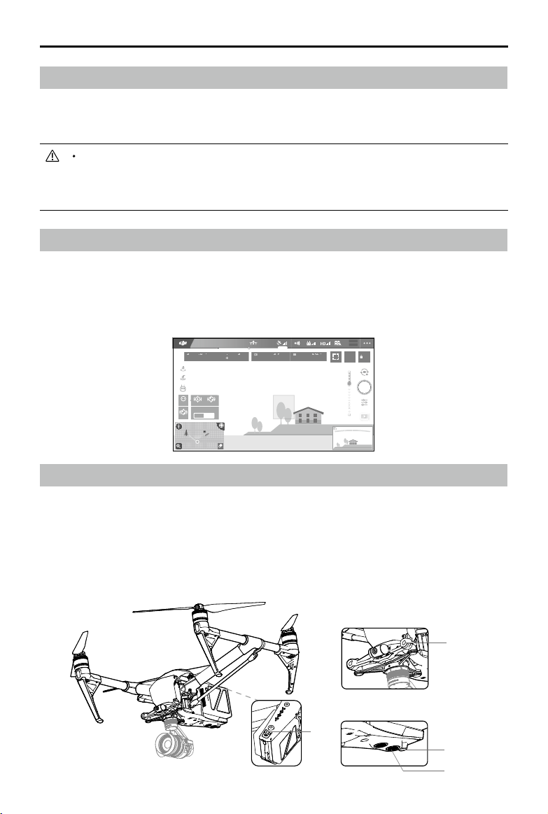
Vision System and Infrared Sensing System
The main components of the Vision System are located on the front and bottom of the Inspire 2,
including [1] [2] two stereo vision sensors and [3] two ultrasonic sensors. The Vision Sys tem uses
ultrasound and image data to help the aircraft maintain its current position, enabling precision hovering indoors or in environments where a GPS signal is not available. The Vision System constantly
scans for obstacles, allowing the Inspire 2 to avoid them by going over, around, or hovering.
The Infrared Sensing System consists [4] of two infrared modules on top side of the aircraft. These
scan for obstacles on top side of the aircraft and is active in certain ight modes.
[4]
2016 DJI. All Rights Reserved.
©
[1]
[2]
[3]
23
Page 24

INSPIRE 2 User Manual
Detection Range
The detection range of the Vision System and Infrared Sensing System are depicted as follow.
Note that the aircraft cannot sense and avoid the obstacles that are not within the detection range.
Calibration
Forward and Downward Vision Systems cameras installed on the aircraft are calibrated on delivery.
However these cameras are vulnerable to excessive impact and will require occasional calibration
via DJI Assistant 2.
Calibration via Visual Calibration Plate
1. Make sure that the aircraft is in landing mode. Power on the aircraft and toggle the USB Mode
Switch down.
2. Connect the Inspire 2 and the PC via the USB cable (with Double A ports)
3. Launch DJI Assistant 2 and login with a DJI account.
4. Click Inspire 2 and the calibration button.
5. Place the side of visual calibration plate with the dots facing the forward vision system, and follow
the instructions in the DJI Assistant 2 to complete calibration.
6. Place the aircraft straightly, and ensure the side of visual calibration plate with dots is facing
the downward vision system, and follow the instructions in the DJI Assistant 2 to complete
calibration.
2016 DJI. All Rights Reserved.
24
©
Page 25

Calibrating via Screen
ON OFF
Auto Hold
Follow the steps below to calibrate the camera.
INSPIRE 2 User Manual
Point the aircraft toward the screen
01
02
Align the boxes
03
Pan and tilt the aircraft
DO NOT power off or unplug the USB cable after calibration and wait for the data calculation.
Using Vision System
Vision System is activated automatically when the Inspire 2 is powered on. No manual action is
required. Vision System is typically used in the indoor environment where no GPS is available. By
using the sensors on the Vision system, Inspire 2 can perform precision hovering even when no GPS
is available.
Follow the steps below to use Vision System:
1. Toggle the ight mode switch to P-mode.
2. Place the aircraft on a flat surface. Note that the Vision System cannot work
properly on surfaces without clear pattern variations.
3. Turn on the aircraft. The aircraft status indicator will ash green two times, which
indicates the Vision System is ready. Gently push the left stick up to lift off and
the aircraft will hover in place.
2016 DJI. All Rights Reserved.
©
25
Page 26

INSPIRE 2 User Manual
Assisted Braking from Obstacle Sensing
Powered by the Obstacle Sensing, the aircraft will now be able to actively brake when obstacles
are detected around the aircraft. Note that Obstacle Sensing function works best when lighting
is adequate and the obstacle is clearly marked or textured. The aircraft must y at no more than
31mph (50kph) to allow sufcient braking distance.
The performance of your Vision System and Infrared Sensing System are affected by the surface
being own over. Ultrasonic sensors may not be able to accurately measure distances when
operating above sound-absorbing materials and the camera may not function correctly in
suboptimal environments. The aircraft will switch from P-mode to A-mode automatically if neither
GPS nor Vision System and Infrared Sensing System are available. Operate the aircraft with
great caution in the following situations:
a) Flying over monochrome surfaces (e.g. pure black, pure white, pure red, pure green).
b) Flying over a highly reective surfaces.
c) Flying at high speeds of over 31mph (50kph) at 2 meters or over 11mph (18kph) at 1
meter.
d) Flying over water or transparent surfaces.
e) Flying over moving surfaces or objects.
f) Flying in an area where the lighting changes frequently or drastically.
g) Flying over extremely dark (lux < 10) or bright (lux > 100,000) surfaces.
h) Flying over surfaces that can absorb sound waves (e.g. thick carpet).
i) Flying over surfaces without clear patterns or texture.
j) Flying over surfaces with identical repeating patterns or textures (e.g. tiling).
k) Flying over inclined surfaces that will deect sound waves away from the aircraft.
l) Flying over obstacles with too small effective infrared reective surface.
m) DO NOT position the sides of two aircraft toward each other to avoid interference between
the 3D infrared modules.
n) DO NOT cover the protective glass of the infrared module. Keep it clean and undamaged.
Keep sensors clean at all times. Dirt or other debris may adversely affect their effectiveness.
Vision System is only effective when the aircraft is at altitudes of 0.3 to 10 meters.
The Vision System may not function properly when the aircraft is ying over water.
The Vision System may not be able to recognize pattern on the ground in low light
conditions (less than 100 lux).
Do not use other ultrasonic devices with frequency of 40 KHz when Vision System is in
operation.
Keep animals away from the aircraft when Vision System is activated. The sonar sensor
emits high frequency sounds that are audible to some animals.
2016 DJI. All Rights Reserved.
26
©
Page 27

INSPIRE 2 User Manual
Flight Recorder
Flight data is automatically recorded to the internal storage of the aircraft. This includes flight
telemetry, aircraft status information, and other parameters. To access this data, connect the aircraft
to the PC through the USB port and launch the DJI Assistant 2.
Attaching and Detaching the Propellers
Attaching the Propellers
Refer to "Attaching Propellers" for details.
Detaching the Propellers
Press down the spring pad and rotate the propeller lock to remover the propeller.
Be aware of the sharp edges of the propellers. Handle with care.
Use only the DJI approved propellers. Do not mix propeller types.
Check that the propellers and motors are installed correctly and rmly before every ight.
Ensure that all propellers are in good condition before each ight. DO NOT use aged,
chipped, or broken propellers.
To avoid injury, STAND CLEAR of and DO NOT touch propellers or motors when they are
spinning.
ONLY use original DJI propellers for a better and safer ight experience.
DJI Intelligent Flight Battery
The DJI Intelligent Flight Battery has a capacity of 4280mAh, voltage of 22.8V, and smart chargedischarge functionality. It can only be charged with an appropriate DJI approved charger.
DJI Intelligent Flight Battery Functions
1. Battery Level Display: LEDs display the current battery level.
2. Auto-discharging Function: The battery automatically discharges to below 70% of total power
when it is idle (press the power button to check battery level will cause battery to exit idle state)
for more than 10 days to prevent swelling. It takes around 3 days to discharge the battery to
65%.It is normal to feel moderate heat emitting from the battery during the discharge process.
Discharge thresholds can be set in the DJI GO 4 app.
3. Balanced Function: Automatically balances the voltage of each battery cell when charging.
4. Over charge Protection: Charging automatically stops when the battery is fully charged.
5. Temperature Protection: The battery will only charge when the temperature is between 5 °C (41°F)
and 45°C (113°F).
6. Over Current Protection: Battery stops charging when high amperage (more than 10A) is
detected.
7. Over Discharge Protection: Over-discharging can seriously damage the battery. The current output
will be cut off once the battery cell is discharged to 2.8V when it is not in ight mode. To guarantee
the ight safety, the over-discharge protection function will not be activated during ight.
8. Short Circuit Protection: Automatically cuts the power supply when a short circuit is detected.
9. Battery Cell Damage Protection: The DJI GO 4 app displays a warning message when a
damaged battery cell is detected.
2016 DJI. All Rights Reserved.
©
27
Page 28

INSPIRE 2 User Manual
10. Sleep Mode: Sleep mode is entered to save power when the aircraft is not ying.
11. Communication: Battery voltage, capacity, current, and other relevant information is provided to
the aircraft’s to the main controller.
12. Paring Batteries: Ensure each battery pair is charged and discharged simultaneously to prolong
their service life and for a better ight experience. It is recommended to pair two batteries with a
similar life cycle inside DJI GO 4 app.
13. Heating: Batteries are able to work even in cold weather, ensuring a safe ight.
Refer to
Disclaimer
and
Intelligent Flight Battery Safety Guidelines
before use. Users take
full responsibility for all operations and usage.
Charging the Intelligent Flight Battery
The Inspire 2 Intelligent Flight Battery Charging Hub is designed for use with the Inspire 2 Battery
Charger. It charges up to four Intelligent Flight Batteries simultaneously. The battery pair with more
stored power will be charged rst. The Charging Hub will intelligently charge batteries in sequence
according to battery power levels from high to low, if batteries are not paired. Pairing can be carried
out using the DJI GO 4 app. The Micro USB port is used for rmware updates.
Overview
[1]
[2]
[3]
[6]
[5]
[4]
[7]
[1] Power Port
[2] Charging Port
[3] Charging Port Cover
[4] Battery Charging Level Indicators
[5] Cover/Battery Release Button
[8]
[6] Status LEDs
[7] Firmware Update Port (Micro USB)
[8] Buzzer Switch
Connecting to a Power Source
Connect the standard Inspire 2 Battery Charger to a power outlet (100-240V, 50/60Hz), then
uncover the rubber cover on the power port to connect the Charging Hub to the Inspire 2 Battery
Charger*.
Power OutletChargerCharging Hub
* It will take approximately 1.5 hours to fully charge the Inspire 2 Intelligent Flight Battery, and 3 hours for
the remote controller. It will take a longer time to charge the Intelligent Flight Battery and remote controller
together.
2016 DJI. All Rights Reserved.
28
©
Page 29

INSPIRE 2 User Manual
Connecting Batteries
Press the release button and open the corresponding charging port cover. Insert the Intelligent
Flight Battery into the charging port to begin charging. The battery pair with more stored power
will be charged rst. The Charging Hub will intelligently charge batteries in sequence according to
battery power levels from high to low, if batteries are not paired. Pairing can be carried out using
the DJI GO 4 app. Refer to the "Status LED Description” section for more information about Status
LED blinking patterns. The buzzer will begin beeping when charging is complete. Refer to the
“Buzzer Beeping Description” for more information about buzzer beeping patterns.
LED1
LED2
LED3
LED4
Battery Level Button
Always align the grooves on the Intelligent Flight Battery with the battery slot tracks.
Press the release button to detach batteries after charging is complete.
DO NOT leave metal terminals exposed to open air when not in use.
Status LED Descriptions
Status LED (Charging Hub) Description
Blinks Green Charging
— Solid Green Fully charged
Blinks Red Battery Charger error
— Solid Red Intelligent Flight Battery error
Blinks Yellow
Battery temperature too high/low. Temperature
must be within operating range (5°-40℃)
— Solid Yellow Ready to charge
Battery Level Indicators while Charging (Battery)
LED1 LED2 LED3 LED4 Battery Level
0%~50%
50%~75%
75%~100%
Fully Charged
2016 DJI. All Rights Reserved.
©
29
Page 30

INSPIRE 2 User Manual
Charging Protection LED Display
The table below shows battery protection mechanisms and corresponding LED patterns.
Battery Level Indicators for Battery Protection
LED1 LED2 LED3 LED4 Blinking Pattern Battery Protection Item
LED2 blinks twice per second Over current detected
LED2 blinks three times per
second
Short circuit detected
LED3 blinks twice per second Over charge detected
LED3 blinks three times per
second
LED4 blinks twice per second
LED4 blinks three times per
second
Over-voltage charger detected
Charging temperature is too
low (<0°C)
Charging temperature is too
high (>40°C)
After any of the above mentioned protection issues are resolved, press the button to turn off the
Battery Level Indicator. Unplug the Intelligent Flight Battery from the charger and plug it back in to
resume charging. Note that you do not need to unplug and plug the charger in the event of a room
temperature error, the charger will resume charging when the temperature falls within the normal
range.
DJI does not take any responsibility for damage caused by third-party chargers.
How to discharge the Intelligent Flight Battery before transport the batteries for long trip:
Fly the aircraft outdoors until there is low battery power left, or until the battery can no
longer be turned on.
Buzzer Beeping Description
Toggle the buzzer switch to turn on/off the warning sound.
Descriptions Beeping Pattern
Toggle the buzzer switch to turn it on Quick beeping
Connect to the Battery Charger Quick beeping
A battery pair is fully charged Quick beeping
Four Intelligent Flight Batteries are fully charged
Updating the Firmware
Alternating two short and one long beeps,
last for about 1 hour
DJI will release rmware updates when available. Refer to the ofcial DJI website and follow the
instructions below to update the rmware.
1. Download the latest rmware update program from the ofcial DJI website.
(http://www.dji.com/inspire-2/info#downloads)
2016 DJI. All Rights Reserved.
30
©
Page 31

INSPIRE 2 User Manual
2. Turn on the Charging Hub, then connect it to a computer using a Micro USB cable.
3. Run the rmware update program. Press the update button and wait for the process to nish.
4. The Charging Hub will automatically restart when the update has been successfully completed.
5. Repeat this process if the rmware update fails for any reason.
Using the Battery
Powering ON/OFF
Powering On: Press the Power Button once, then press again and hold for 2 seconds to power on.
The Power LED will turn red and the Battery Level Indicators will display the current
battery level.
Powering Off: Press the Power Button once, then press again and hold for 2 seconds to power off.
Heating the Battery
Manual Heating: When the battery is powered off, press and hold the power button for 3 seconds to
initiate the battery to warm up manually.
The battery will start to warm up when the temperature is below 59℉(15℃)with the LED1&2 and
LED3&4 blinking alternatively. The temperature of the battery will stop increasing when it reaches
68℉(20℃).
The temperature of the battery will be between 59°-68℉(15°-20℃)when it is above 59℉(15℃)with
the LED1 and LED4 blinking alternatively, lasting for approximately 30 minutes. And then it will be
powered off automatically.
Auto Heating: Insert the batteries into the aircraft and power on. When the temperature of the battery
is below 59℉(15℃), the battery will warm up automatically, and you may check the LED for current
power level.
2016 DJI. All Rights Reserved.
©
31
Page 32

INSPIRE 2 User Manual
Low Temperature Notice:
1. The performance of the intelligent Flight Battery is significantly reduced when flying in a low
temperature environments (those with air temperatures below 5℃). Ensure that the battery is fully
charged and the cell voltage is at 4.35 V before each ight.
2. If the DJI GO 4 app displays the “Critical Low Battery Level Warning” when flying in low
temperature environments, stop ying and land the aircraft immediately. You will still be able to
control the aircraft’s movement when this warning is triggered.
3. In extremely cold weather, the battery temperature will continuously decrease even it has heating
function. In such case, the battery capacity will slump with the ight time sharply reduce.
4. To ensure optimum performance, keep the Intelligent Flight Battery’s core temperature above
20℃ when in use.
5. Battery insulation paste is available for you to use.
Checking the battery level
The Battery Level Indicators display how much remaining power the battery has. When the battery
is powered off, press the Power Button once. The Battery Level Indicators will light up to display the
current battery level. See below for details.
The Battery Level Indicators will also show the current battery level during discharging. The
indicators are dened below.
: LED is on.
: LED is off.
Battery Level
: LED is ashing.
LED1 LED2 LED3 LED4 Battery Level
87.5%~100%
75%~87.5%
62.5%~75%
50%~62.5%
37.5%~50%
25%~37.5%
12.5%~25%
0%~12.5%
2016 DJI. All Rights Reserved.
32
©
Page 33

Remote Controllers
This chapter describes the features
of the remote controller that includes
aircraft and remote controller operations
and dual remote controller mode.
Page 34

Remote Controller
RemoteControllerProle
The Inspire 2 remote controller is a multi-function wireless communication device that integrates a dual
frequency video downlink system and the aircraft remote control system. The 5.8 GHz video downlink
is recommended for urban areas to resist interference, 2.4 GHz is good for long transmission distances
in open areas. The remote controller features a number of camera control functions, including photo/
video capture as well as gimbal control. The battery level is displayed via LED indicators on the front
panel of the remote controller. When in dual remote controller mode, each of the two remote controllers
separately control aircraft and camera and can be up to 328 feet (100m) apart.
Compliance Version: The remote controller is compliant with local compliance and
regulations.
Operating Mode: Control can be set to Mode 1 or Mode 2, or to a custom mode.
Mode 1: The right stick serves as the throttle.
Mode 2: The left stick serves as the throttle.
Do not operate more than 3 aircrafts within in the same area (size equivalent to a soccer
eld) to prevent transmission interference.
Remote Controller Operations
Powering On And Off The Remote Controller
The Inspire 2 remote controller is powered by a 2S rechargeable battery with a capacity of
6000mAh. The battery level is indicated by the Battery Level LEDs on the front panel. Follow the
steps below to power on your remote controller:
1. When powered off, press the Power Button once and the Battery Level LEDs will display the
current battery level.
2. Then, press and hold the Power Button to power on the remote controller.
3. The Remote Controller will beep when it powers on. The Status LED will blink green (slave remote
controller blinks solid purple) rapidly, indicating that the remote controller is linking to the aircraft.
The Status LED will show a solid green light when linking is completed.
4. Repeat step 2 to power off the remote controller after nish using it.
2016 DJI. All Rights Reserved.
34
©
Page 35

Charging Remote Controller
Charge the remote controller via supplied charger.
INSPIRE 2 User Manual
Power Outlet
B
B
Controlling Camera
Shoot videos or images and adjust camera settings via the Shutter Button, Camera Settings Dial
Video Recording Button and Gimbal Dial on the remote control.
[4]
[3]
[1] Camera Settings Dial
[1]
[2]
Turn the dial to adjust camera settings such as ISO, shutter speed, and aperture without letting
go of the remote controller. Press down on the dial to toggle between these settings.
[2] Shutter Button
Press to take a photo. If burst mode is activated, multiple photos will be taken with a single
press.
[3] Video Recoding Button
Press once to start recording video, then press again to stop recording.
[4] Gimbal Dial
Control the tilt of the gimbal.
Controlling Aircraft
This section explains how to use the various features of the remote controller. The Remote Controller
is set to Mode 2 by default.
Stick Neutral/ mid point: Control sticks of the Remote Controller are placed at the central
position.
Move the Stick: The control stick is pushed away from the central position.
2016 DJI. All Rights Reserved.
©
35
Page 36

INSPIRE 2 User Manual
Remote
Controller
(Mode 2)
Aircraft
indicates nose direction)
(
Remarks
Moving the left stick up and down changes the
aircraft’s elevation.
Push the stick up to ascend and down to descend.
Push the throttle stick up to takeoff.
When both sticks are centered, the Inspire 2 will
hover in place.
The more the stick is pushed away from the
center position, the faster the Inspire 2 will change
elevation. Always push the stick gently to prevent
sudden and unexpected elevation changes.
Moving the left stick to the left or right controls the
rudder and rotation of the aircraft.
Push the sick left to rotate the aircraft counter clockwise, and push the stick right to rotate the aircraft
clockwise. If the stick is centered, the Inspire 2 will
stay facing its current direction.
The more the stick is pushed away from the center
position, the faster the Inspire 2 will rotate.
Moving the right stick up and down changes the
aircraft’s forward and backward pitch.
Push the stick up to y forward and down to y
backward. The Inspire 2 will hover in place if the
stick is centered.
Push the stick further away from the center position for a
larger pitch angle (maximum 35˚) and faster ight.
Moving the right stick control left and right changes
the aircraft’s left and right pitch.
Push left to y left and right to y right. The Inspire 2
will hover in place if the stick is centered.
Push the stick further away from the center position for
a larger pitch angle (maximum 35˚) and faster ight.
2016 DJI. All Rights Reserved.
36
©
Gimbal Dial: Turn the dial to the right, and the
camera will shift to point upwards. Turn the
dial to the left, and the camera will shift to point
downwards. The camera will remain in its current
position when dial is static.
Press the Intellighent Flight Pause button once to
exit from the ActiveTrack, TapFly and Intelligent
Navigation ight mode. The aircraft will hover at
the current position.
Page 37

Adjusting Controller Sticks
Hold and twist the controller sticks clockwise or counter clockwise to
adjust the length of the controller sticks. A proper length of controller
sticks can improve the controlling accuracy.
Flight Mode Switch
Toggle the switch to select the desired ight mode.
Choose between; P-mode, S-mode and A- mode.
INSPIRE 2 User Manual
Position Figure Flight Mode
Position
1
Position
2
Position
3
P-mode (Positioning): P-mode works best when the GPS signal is strong. The aircraft utilizes GPS,
stereo Vision System and Infrared Sensing System to stabilize, avoid obstacles or track moving subjects.
Advanced features such as TapFly and ActiveTrack are enabled in this mode.
S-mode (Sport): The handling gain values of the aircraft are adjusted to enhance aircraft maneuverability.
Note that Obstacle Sensing systems are disabled in this mode.
A-mode (Attitude): When neither the GPS nor the Vision System is available, the aircraft will only use its
barometer for positioning to control the altitude.
The Flight Mode is locked in P Mode by default, regardless of switch position. To switch ight modes, go
to Camera view in the DJI GO 4 app, tap
ight modes, toggle the switch to P and then to S to y in Sport Mode.
P-mode
S-mode
A-mode
and enable “Multiple Flight Modes”. After enabling multiple
Position 1
Position 2
Position 3
Transformation Switch / RTH Button
The Transformation Switch / RTH Button combination serves two functions. Toggle the switch up or
down to raise or lower the landing gear. Or, press the button to activate the Return to Home (RTH)
procedure. Intelligent landing gear will automatically raise after takeoff and lower when landing.
They can also be controlled manually using the Transformation Switch.
Transformation Switch
This switch has two positions. The effect of toggling the switch to any of these positions is dened below:
Lower Raise
2016 DJI. All Rights Reserved.
©
37
Page 38

INSPIRE 2 User Manual
1. Raise: Raise the landing gear to its upper most position.
2. Lower: The landing gear will lower to its lowest position for landing.
Do not raise the landing gear when the aircraft is on the ground. Ensure the landing gear
is lowered before landing.
The aircraft will not be able to land if the landing gear does not lower.
RTH button
Press and hold this button to start the Return to Home (RTH) procedure. The LED around the RTH
Button will blink white to indicate the aircraft is entering RTH mode. The aircraft will then return to
the last recorded Home Point. Press this button again to cancel the RTH procedure and regain the
control of the aircraft.
2016 DJI. All Rights Reserved.
38
©
Page 39

INSPIRE 2 User Manual
Connecting Mobile Device
Tilt the Mobile Device Holder to the desired position. Press the button on the side of the Mobile Device Holder
to release the clamp, and then place your mobile device into the clamp. Adjust the clamp to secure your
mobile device. Then connect your mobile device to the remote controller with a USB cable. Plug one end of
the cable into your mobile device, and the other end into the USB port on the back of the remote controller.
2
1
3
Optimal Transmission Range
The signal transmission between aircraft and remote controller perform best within the range that
displayed in the picture shown below:
90° 60°
5.8G
Strong Weak
2.4G
Optimal Transmission RangeOptimal Transmission Range
Ensure the aircraft is ying within the optimal transmission range. Adjust the distance and position
between the operator and the aircraft to achieve optimal transmission performance. The position
of the antennas required for optimal transmission range varies in the frequency of 5.8G and 2.4G.
Please place the antennas based on the actual operating frequency.
Dual Remote Controllers Mode
More than one remote controller can connect to the same aircraft in Dual Remote Controller mode.
In Dual Controllers mode, the “Master” remote controller operator controls the orientation of the
aircraft, while the “Slave” remote controller controls the movement of the gimbal and camera
operation. “Master” and "Slave" remote controllers communicate each other via WiFi.
2016 DJI. All Rights Reserved.
©
39
Page 40

INSPIRE 2 User Manual
Master Remote
Controller
Slave Remote
Controller
In Dual Controllers Mode, the Master remote controller controls the gimbal in both pitch
and pan directions when it takes charge. The Slave remote controller is able to control the
gimbal in pitch, pan and roll directions when it takes charge.
Russian and Israel don't support Dual Remote Controller mode.
Setting Up Dual Remote Controllers Mode
Dual Remote Controllers mode is disabled by default. Users must enable this feature on the “Master”
remote controller by through the DJI GO 4 app. Follow the steps below for setup:
“Master” Remote Controller:
1. Connect the remote controller to your mobile device and launch the DJI GO 4 app.
2. Go to the Camera page, and tap
to enter the remote controller settings window.
3. Select “Master” set the remote controller as “Master” remote controller.
4. Enter the connection password for the “Slave” remote controller.
2016 DJI. All Rights Reserved.
40
©
Remote Controller Settings
Master and Slave
Set Remote Controller Status
Master ID: 28172d Slave ID: 14f93f
Connection Status:ON Authorization Code:
Remote Controller Calibration
OFF
Master
Slave
666666
Page 41

INSPIRE 2 User Manual
“Slave” Remote Controller:
1. Select “Slave”to set the remote controller as “Slave” remote controller.
Remote Controller Settings
Master and Slave
Master
Set Remote Controller Status
Master ID: 28172d Slave ID: 14f93f
Connection Status:OFF
Search Master
OFF
Slave
Remote controller cannot link to the aircraft if the remote controller is set as “Slave”.
Meanwhile, the “Slave” remote controller cannot control the orientation of the aircraft. Reset
the remote controller to “Master” in DJI GO 4 app if you wish to link the remote controller to
the aircraft.
2. Search the “Master” remote controller in the surrounding area.
Remote Controller Settings
Master and Slave
Master
Set Remote Controller Status
OFF
Slave
Master ID: 28172d Slave ID: 14f93f
Connection Status:OFF
Search Master
3. Select the “Master” remote controller from the "Master" list and input the connection password to
connect to the desired “Master” remote controller.
Search Master
Master
2816f2
28172d
RSSI
-56.00
-22.00
Scan
Connect
Connect
2016 DJI. All Rights Reserved.
©
41
Page 42

INSPIRE 2 User Manual
Remote Controller Status LED
The Status LED reflects connection status between Remote Controller and aircraft. The RTH
LED shows the Return to Home status of the aircraft. The table below contains details on these
indicators.
RTH LED
Status LED
Status LED Alarm Remote Controller Status
— Solid Red ——
— Solid Green ——
— Solid Purple ——
— Solid Blue ——
Slow Blinking
Red
/
Red and Green/ Red and
Yellow Alternate Blinks
RTH LED Sound Remote Controller Status.
— Solid White chime Initiate RTH procedure.
Blinking White D
Blinking White DD
......
D-D-D
None HD Downlink is disrupted.
. . .
.. .. ..
The remote controller set as "Master" but it is not
connected with the aircraft.
The remote controller set as "Master" and it is
connected with the aircraft.
The remote controller set as "Slave" but it is not
connected with the aircraft.
The remote controller set as "Slave" and it is
connected with the aircraft.
Remote controller error.
Send RTH command to aircraft.
Aircraft returning to Home Point.
The Remote Status Indicator will blink red, sound an alert, when the battery level is critically
low.
Linking the Remote Controller
The remote controller is linked to your aircraft before delivery. Linking is only required when using a
new remote controller for the rst time. Follow these steps to link a new remote controller:
1. Power on the remote controller and connect to the mobile device. Launch DJI GO 4 app.
2. Power on the Intelligent Flight Battery.
3. Enter camera view and then tap “Linking Remote Controller” button as shown below.
2016 DJI. All Rights Reserved.
42
©
Page 43

Remote Controller Settings
INSPIRE 2 User Manual
Charge Mobile Phone
Button Customization
C1
C2 Not Defined
Customize with the C1 and C2 button on the back of the Remote Controller.
Linking Remote Controller
Never
Not Defined
4. The remote controller is ready to link. The Remote Controller Status Indicator blinks blue and
"beep" sound is emitted.
5. Locate the Linking button on the front of the aircraft, as shown in the gure shown below. Press
the Linking button to start linking. The Remote Controller Status Indicator will display solid green
if Link is succeed.
Remote controller cannot link to the aircraft if the remote controller is set as “Slave”.
Meanwhile, the “Slave” remote controller cannot control the orientation of the aircraft.
Reset the remote controller to “Master” in DJI GO 4 app if you wish to link the remote
controller to the aircraft.
Remote controller will disconnect from the linked aircraft if a new remote controller is
linked to the same aircraft.
Press the C1 button, C2 button and recording button, can obtain a fast linking.
2016 DJI. All Rights Reserved.
©
43
Page 44

INSPIRE 2 User Manual
Used with the DJI Focus
DJI Focus and DJI Focus Handwheel are fully compatible with the Zenmuse X5S and X4S gimbal
and camera. No calibration is required when using the Focus with the gimbal and camera. Use the
DJI Focus for example.
Connection
To allow communication between the two devices, connect the communication port on the Focus
remote controller to the CAN Bus port on the remote controller using the dedicated CAN Bus cable.
Ensure that the gimbal and camera is set in AF mode.
Refer to "DJI FOCUS User Manual" for more information.
Updating the Home Point
If the Inspire 2 GPS Module for Remote Controller is used, when Follow Me is activated, the aircraft
will automatically follow more precisely. The real-time location of the remote controller will also be
recorded as the Home Point even when the controller is moving, helping ensure a safe return of the
aircraft.
Installation
1. Mount the master part of the GPS Module on the top of the mobile device holder with the help of
the provided adhesive.
1
2016 DJI. All Rights Reserved.
44
©
Page 45

INSPIRE 2 User Manual
2. Fasten the cable and the mobile device holder, and prevent it from dangling with the Velcro
strap. Ensure that the cable hangs down beneath the remote controller alongside one side of an
antenna. DO NOT let the cable pass through the middle of the antennas.
2
3. Stick the CAN hub on the bottom of the remote controller tightly as shown below.
4. Insert the cable end to the CAN Bus port on the remote controller.
5. Installation is complete.
4
3
2016 DJI. All Rights Reserved.
©
45
Page 46

INSPIRE 2 User Manual
DO NOT let the cable pass through the middle of the antennas, or it may negatively affect
the signal.
The side marked with the DJI logo should face out when the master part is properly
mounted.
DO NOT cover the GPS Module with metal.
Ensure the cable is inserted correctly or the CAN Bus port may be damaged.
Always power off the remote controller when mounting the GPS Module.
It is recommended to leave the GPS Module mounted, as frequent installation and
removal will weaken the adhesive.
Other equipment can be connected to the CAN Bus port on the CAN hub, e.g. DJI Focus.
Setting Up Dynamic Home Point
Follow the steps below to setup Dynamic Home Point:
1. Connect to the mobile device and launch the DJI GO 4 app and go to the “Camera” page.
2. Tap“
3. Tap“
4. The aircraft status indicator blinks green to show Home Point is set successfully.
”and select“ ”, to reset the remote controller’s coordinates as the new Home Point.
”and select“ ”, to reset the aircraft’s coordinates as the new Home Point.
2016 DJI. All Rights Reserved.
46
©
Page 47

Gimbal and Camera
This chapter provides the technical
specications of the camera and explains
the working mode of the gimbal.
Page 48

Camera and Gimbal
Camera
CameraProle
Featuring M4/3 CMOS sensor, the Zenmuse X5S supports up to 20.80 MP still photo capture. It is
capable of capturing 5.2K 30fps CinemaDNG video and Apple ProRes Video as well as 4K 60fps
using H.264. The Zenmuse X5S is built using the M4/3 interchangeable lens standard. A variety
of shooting modes, including single shooting, burst shooting and interval shooting, provide more
options of capture. Burst and AEB is available, with up to 14 stills.
When the DJI CINESSD is in use, the Zenmuse X5S is able to record lossless videos with a bitrate
of 5.2 Gbps in the CinemaDNG format or capture DNG stills at 20fps continuously.
When mounted on the Inspire 2, the 3-axis gimbal provides a stable platform for the camera to get clear
shots even during rapid maneuvering. The gimbal tilts the camera across a -130° to +40° pitch angle
and pans ± 320° in both directions. Live HD video from the camera is streamed to the DJI GO 4 app.
Camera Micro SD Card Slot
To store your photos and videos, plug in the Micro SD card into the slot shown below before
powering on the Inspire 2. The Inspire 2 comes with a 16GB Micro SD card and supports up to a
128GB Micro SD card. A UHS-3 type Micro SD card is recommended, because the fast read and
write capability of these cards enables you to store high-resolution video data.
The Inspire 2 currently supports the following Micro SD cards, and will continue to support
more cards in future.
Sandisk Extreme 32GB UHS-3 MICROSDHC
Sandisk Extreme 64GB UHS-3 MICROSDXC
Panasonic 32GB UHS-3 MicroSDHC
Panasonic 64GB UHS-3 MicroSDXC
Samsung PRO 32GB UHS-3 MicroSDHC
Samsung PRO 64GB UHS-3 MicroSDXC
Samsung PRO 128GB UHS-3 MicroSDXC.
Do not remove Micro SD card from the Inspire 2 when it is powered on.
USB Port
Power on the Inspire 2 and then connect a USB cable to the USB port to download photos or videos
from the Inspire 2 to your computer.
2016 DJI. All Rights Reserved.
48
©
Page 49

INSPIRE 2 User Manual
Power on the aircraft before attempting to download the les.
Camera Operation
Remote Controller
Use the Shutter and Record button on the remote controller to shoot the images or the videos. For
more information about how to use these buttons, refer to “Controlling Camera”.
DJI GO 4 app
Use the DJI GO 4 app to shoot the images or the videos. For more information, refer to “Zenmuse
X5S User Manual”.
Gimbal
GimbalProle
The 3-axis Gimbal provides a steady platform for the attached camera, allowing you to capture
stabilized images and video.
+40°
0°
-130°
-320° -20°
+320°
Using DJI GO 4 App to Control Gimbal
Follow the steps below to use DJI GO 4 app to control the gimbal orientation:
1. Launch DJI GO 4 app, enter camera page.
2. Tap and press on the screen until a blue circle is shown.
3. Slide to control the gimbal orientation within the “Camera” page as shown below.
2016 DJI. All Rights Reserved.
©
+20°
49
Page 50

INSPIRE 2 User Manual
ISO
SHUT TEREVWB
F
CAPAC ITY
SD TIME
4.07V
In Flight (GPS)
200 0.3 Auto
5.61/200
30M
4KP30
P-GPS
H
10.0
VS 2.0M/S VPS 2. 0MH.S 10.0 KM/H
12
R
09:29
MD
4KP3020:12 384G
74%
70%
AF/ MF
4.07V
AE
Gimbal Operation Modes
Three Gimbal operation modes are available. Switch between the different operation modes on the
Camera page of the DJI GO 4 App. Note that your mobile device must be connected to the remote
controller for changes to take effect. Refer to the table below for details:
2016 DJI. All Rights Reserved.
50
©
Pitch Pan
The angle between Gimbal’s orientation and aircraft’s nose remains
Follow Mode
constant at all times. One user alone can control the pitch motion of
the Gimbal, but a second user is required to control the pan motion
using a second remote controller.
The Gimbal’s motion is independent of the aircraft’s orientation. One
Free Mode
user alone can control the pitch motion of the Gimbal, but a second
user is required to control the pan motion using a second remote
controller.
Tap to force the Gimbal orientation to re-align with aircraft’s
Reset
orientation by panning from gimbal’s current orientation. Pitch angle
will remain unchanged during the re-alignment.
Roll
Page 51

INSPIRE 2 User Manual
Gimbal motor error may occur in these situations: (1) Gimbal is placed on uneven ground.
(2) Gimbal has received an excessive external force, e.g. a collision. Please take off from
at, open ground and protect the gimbal after powering up.
Flying in heavy fog or cloud may make the gimbal wet, leading to a temporary failure. The
gimbal will recover when it dries out.
Using CINESSD
Using an Inspire 2 as an example.
Storing Files
1. Power off the aircraft.
2. Insert the CINESSD into the aircraft. If the CINESSD is not detected, check if it is inserted correctly.
3. Power on the aircraft.
4. Information about the CINESSD will be available in the DJI GO™ 4 app.
Exporting Files
1. Power off the aircraft. Remove the batteries and then the CINESSD.
2. Insert the CINESSD into the DJI CINESSD Station, then connect the station to a computer via a
USB cable.
1
USB Port
2
2016 DJI. All Rights Reserved.
©
51
Page 52

INSPIRE 2 User Manual
3. When connected, an icon named “DJI_A” followed by a number sequence will appear. Click to
start the le export.
4. Safely remove the station before unplugging it from your computer.
No additional software is required for exporting data from the CINESSD. You may also use
the following DJI software based on your system.
Windows: DJI Camera Exporter.
Mac: DJI CINELIGHTTM.
DO NOT remove the CINESSD when it is powered on.
Insert the CINESSD before connecting the station to the computer.
The station icon will vary based on your computer operating system.
Deleting Files
To guarantee the high performance of the DJI CINESSD, the station only supports le exporting. To
delete les, please insert the CINESSD into the aircraft and launch the DJI GO 4 app to format the
CINESSD to free up storage space.
Ensure to back up your les before formatting the DJI CINESSD.
Specications
Capacity 120 GB/ 240 GB/ 480 GB
Size 105.5 mm×27 mm×7 mm
Weight 42.5 g
Operation Temperature Range 32° to 104° F (0° to 40° C)
Storage Temperature Range -40° to 185° F (-40° to 85 ℃)
Humidity 5% to 95%, non-condensing
2016 DJI. All Rights Reserved.
52
©
Page 53

DJI GO 4 App
This chapter describes the four main
GUI of the DJI GO 4 app.
Page 54

DJI GO 4 App
ISO
SHUT TEREVWB
F
CAPAC ITY
SD TIME
The DJI GO 4 app is a new mobile app designed specifically for the Inspire 2. Use this app to
control the gimbal, camera and other features of your flight system. The app also comes with
Map, Store a User Center, for conguring your aircraft and sharing your content with friends. It is
recommended that you use a tablet for the best experience.
INSPIRE 2
Always keep abreast of local flight regulations
before flying !
CONNECTED
Equipment
Editor Skypixel
GO FLY
Me
Camera
The Camera page contains a live HD video feed from the Inspire 2’s camera. You can also
congure various camera parameters from the Camera page.
1 2 3 4 5 6 7 8 9 10 11
4.07V
28
READY TO GO (GPS)
200 0.3 Auto
5.61/200
P-GPS
4KP30
12
R
09:29
4KP3020:12 384G
27
26
25
24
23
22
H
10.0
30M
MD
VS 2.0M/S VPS 2.0MH.S 10.0 KM/H
74%
70%
AF/ MF
4.07V
AE
12
13
14
15
16
17
18
19
20
2016 DJI. All Rights Reserved.
54
©
21
Page 55

INSPIRE 2 User Manual
1. System Status
READY TO GO (GPS)
: This icon indicates aircraft ight status and various warning messages.
2. Battery Level Indicator
: The battery level indicator provides a dynamic display of the battery level. The colored
zones on the battery level indicator represent the power levels needed to carry out different
functions.
3. Flight Mode
: The text next to this icon indicates the current ight mode.
Tap to congure the MC (Main Controller) Settings. These settings allow you to modify ight limits
and set gain values.
4. Camera Parameters
Displays camera settings parameters and capacity.
5. GPS Signal Strength
: Shows the current GPS signal strength. White bars indicate adequate GPS strength.
6. Obstacle Sensing Function Status
: Tap into this button to enable or disable features provided by the Vision System.
7. Remote Controller Signal Strength
: This icon shows the strength of the remote controller signal.
8. HD Video Link Signal Strength
: This icon shows the strength of the HD video downlink connection between the aircraft
and the remote controller.
9. Focus/Metering Button
/ : Tap to switch between focus and metering mode. Tap to select object for focusing or
metering.
10. Battery Level
: This icon shows the current battery level.
Tap to view the battery information menu, set the various battery warning thresholds, and view
the battery warning history.
11. General Settings
: Tap to enter general setting menu for setting metrics, enabling livestream, display ight
routes and so on.
12. AF/MF
: Tap to switch the focus mode.
13. Auto Exposure Lock
: Tap to lock the exposure value.
AE
2016 DJI. All Rights Reserved.
©
55
Page 56

INSPIRE 2 User Manual
14. Photo/Video Button
: Tap to switch between photo and video recording modes.
15. Gimbal Slider
: Displays the pitch of the gimbal.
16. Shoot / Record Button
/ : Tap to start shooting photos or recording video.
17. Camera Settings
: Tap to set ISO, shutter and auto exposure values of the camera.
18. Playback
: Tap to enter the playback page and preview photos and videos as soon as they are captured.
19. Manual Focus
Only effective in MF mode.
20. FPV
FPV only for tablet. Pinch to zoom in or out the window.
displayed when obstacles are in detection range.
: Red bars are displayed when obstacles are close to the aircraft. Orange bars are
:Tap to zoom in the FPV window to the middle of the screen.
21. Flight Telemetry
30
M
10.0
H
MD
VS 2.0M/S VPS 2.0MH.S 10.0 KM/H
(1) Tap to switch to the map view.
(2) Flight Attitude and Radar Function:
N
The red arrow shows which direction the aircraft is facing.
The ratio of the gray area to the blue area indicates the aircraft’s pitch.
The horizontal level of the gray area indicates the aircraft’s roll angle.
2016 DJI. All Rights Reserved.
56
©
Page 57

INSPIRE 2 User Manual
Blue line indicates the current position of the gimbal’s tilt motor.
The outmost grey circle displays current power capacity.
(3) Flight Parameters:
Altitude: Vertical distance from the Home Point.
Distance: Horizontal distance from the Home Point.
Vertical Speed: Movement speed across a vertical distance.
Horizontal Speed: Movement speed across a horizontal distance.
(4) Aircraft Distance:
The horizontal distance between the aircraft and the operator.
22. Spotlight Pro
:Tap to use the Spotlight Pro function.
23. Intelligent Flight Mode
: Display the current mode. Tap to select Intelligent Flight Mode.
24. Smart RTH
: Initiate RTH home procedure. Tap to have the aircraft return to the last recorded home
point.
25. Gimbal Working Modes
Follow mode, free mode and reset mode are included.
26. Auto Takeoff/Landing
/ : Tap to initiate auto takeoff or landing.
27. Livestream
: This icon indicates the current video feed is being broadcast live on YouTube. Ensure that
mobile data service is available on your mobile device.
28. Back
: Tap this icon to return to the main menu.
Editor
An intelligent video editor is built into the DJI GO 4 app. After recording several video clips and
downloading them to your mobile device, go to Editor on the home screen. You can then select a
template and a specied number of clips which are automatically combined to create a short lm
that can be shared immediately.
SkyPixel
Find out about our latest events, featured products and trending Skypixel uploads in the SkyPixel
page.
Me
If you already have a DJI account, you will be able to participate in forum discussions, earn Credits
in the DJI Store, and share your artwork with the community.
2016 DJI. All Rights Reserved.
©
57
Page 58

Flight
This chapter describes the flight safety
and ight restrictions.
Page 59

Flight
Once pre-ight preparation is complete, it is recommended that you use the ight simulator in the
DJI GO 4 app to hone your ight skills and practice ying safely. Ensure that all ights are carried
out in an open area.
Flight Environment Requirements
1. Do not use the aircraft in severe weather conditions. These include wind speeds exceeding 10
m/s , snow, rain and fog.
2. Only y in open areas. Tall structures and large metal structures may affect the accuracy of the
on-board compass and GPS system.
3. Avoid obstacles, crowds, high voltage power lines, trees, and bodies of water.
4. Minimize interference by avoiding areas with high levels of electromagnetism, including base
stations and radio transmission towers.
5. Aircraft and battery performance is subject to environmental factors such as air density and
temperature. Be very careful when ying at high altitudes, as the performance of the battery and
aircraft may be affected.
6. The compass and GPS will not work in Polar Regions. The aircraft will auto switch to A-mode and
use the Vision System for positioning.
Flight Limits and No-Fly Zones
All unmanned aerial vehicle (UAV) operators should abide by all regulations set forth by government
and regulatory agencies including the ICAO and the FAA. For safety reasons, ights are limited by
default, which helps users operate this product safely and legally. Flight limitations include height
limits, distance limits, and No-Fly Zones.
When operating in P-mode, height limits, distance limits, and No-Fly Zones function concurrently to
manage ight safety. In A-mode, only height limits are in effect, which by default prevent the aircraft
altitude from exceeding 1640 feet (500 m) .
Maximumightaltitude&RadiusLimits
Maximum ight altitude and radius limits may be changed in the DJI GO 4 app. Be aware that the
maximum ight altitude cannot exceed 1640 feet (500 meters). In accordance with these settings,
your Inspire 2 will y in a restricted cylinder, as shown below:
Max Height
Max Radius
Home Point
Height of aircraft
when powered on
2016 DJI. All Rights Reserved.
©
59
Page 60

INSPIRE 2 User Manual
GPS Signal Strong Blinking Green
Flight Limits DJI GO 4 App Aircraft Status Indicator
Maximum Flight
Altitude
Max Radius
GPS Signal Weak Blinking Yellow
Aircraft's altitude cannot
exceed the specied value.
Flight distance must be
within the max radius.
Warning: Height
limit reached.
Warning: Distance
limit reached.
None.
Rapid red ashing
when close to the
max radius limit.
Flight Limits DJI GO 4 App
Height is restricted to 26 feet
(8 meters) when the GPS signal
Maximum
Flight
Altitude
Max Radius No limits
is weak and Vision Positioning
is activated. Height is restricted
to 164 feet (50 meters) when the
GPS signal is weak and Vision
Positioning is inactivated.
If the aircraft ies out of the limit, you can still control the aircraft, but you cannot y it any
farther.
If the aircraft ies out of the max radius it will y back within range automatically when GPS
signal is strong.
Warning:
Height limit reached.
Aircraft Status
Indicator
None.
No-Fly Zones
All No-Fly Zones are listed on the DJI official website at http://www.dji.com/flysafe/no-fly. No-Fly
Zones are divided into Airports and Restricted Areas. Airports include major airports and flying
elds where manned aircraft operate at low altitudes. Restricted Areas include borders between
countries or sensitive sites. The details of the No-Fly Zones are explained below:
Airport:
(1) Airport No-Fly Zone are comprised of Take-off Restricted zones and Restricted Altitude Zones.
Each zone features circles of various sizes.
(2) R1 miles (value of the R1 depends on the size and shape of the airport) around the airport is a
Take-off restricted zone, inside of which take off is prevented.
(3) From R1 mile to R1 + 1 mile around the airport the flight altitude is limited to a 15 degree
inclination. Starting at 65 feet (20 meters) from the edge of airport and radiating outward. The
ight altitude is limited to 1640 feet (500 meters) at R1+1 mile.
(4) When the aircraft enters within 320 feet (100 meters) of No-Fly Zones, a warning message will
appear on the DJI GO 4 app.
2016 DJI. All Rights Reserved.
60
©
Page 61

R1
66 feet
1 mile
R2
Airports
1640
feet
INSPIRE 2 User Manual
Airports
66 feet
320 feet
Restricted Areas:
1 mile
R2
R1
(1) Restricted Areas does not have ight altitude restrictions.
(2) R miles around the designated restriction area is a Take-off Restricted area. Aircraft cannot take
off within this zone. The value of R varies based on the denition of the restricted areas.
(3) A “warning zone” has been set around the Restricted Area. When the aircraft approaches within
0.062 miles (100 m) of this zone, a warning message will appear on the DJI GO 4 app.
Restricted Areas
100m R
2016 DJI. All Rights Reserved.
©
61
Page 62

INSPIRE 2 User Manual
GPS Signal Strong Blinking Green
Zone Restriction DJI GO 4 app Prompt
Warning: You are in a No-fly
zone. Take off prohibited.
Warning: You are in a no-y
zone. Automatic landing has
begun.
R1: Warning: You are in a
restricted zone. Descending to
safe altitude.
R2: Warning: You are in a
restricted zone. Maximum ight
altitude is restricted to between
20m and 500m. Fly cautiously.
No-y Zone
Restricted-
altitude ight
zone
Motors will not start.
If the aircraft enters the
restricted area in A-mode,
but is switched to P-mode,
the aircraft will automatically
descend, land, and stop its
motors.
If the aircraft enters the
restricted area in A-mode, but
is switched to P-mode, it will
descend to an appropriate
altitude and hover 15 feet
below the altitude limit.
Aircraft
Status
Indicator
Red ashing
Warning zone
Free zone
Semi-automatic descent: All stick commands are available except the left stick command
during the descent and landing process. Motors will stop automatically after landing.
When flying in a safety zone, the aircraft's status indicator will blink red rapidly and
continue for 3 seconds, then switch to indicate current ying status and continue for 5
seconds at which point it will switch back to blinking red.
For safety reasons, please do not y close to airports, highways, railway stations, railway
lines, city centers, or other sensitive areas. Fly the aircraft only within your line of sight.
No flight restriction applies,
but there will be a warning .
No restrictions. None. None.
Warning: You are approaching
a restricted zone, Fly cautiously.
PreightChecklist
1. Remote controller, Intelligent Flight Battery, and mobile device are fully charged.
2. Propellers are mounted correctly and rmly.
3. Micro SD card has been inserted, if necessary.
4. Gimbal is functioning normally.
5. Motors can start and are functioning normally.
6. The DJI GO 4 app is successfully connected to the aircraft.
7. Ensure that the sensors for the Obstacle Sensing System are clean.
2016 DJI. All Rights Reserved.
62
©
Page 63

INSPIRE 2 User Manual
Calibrating the Compass
Only calibrate the compass when the DJI GO 4 app or the status indicator prompt you to do so.
Observe the following rules when calibrating your compass:
DO NOT calibrate your compass where there is a chance of strong magnetic interference,
such as magnetite, parking structures, and steel reinforcements underground.
DO NOT carry ferromagnetic materials with you during calibration such as cellular phones.
The DJI GO 4 app will prompt you to resolve the compass issue if the compass is affected
by strong interference after calibration is complete. Follow the prompted instructions to
resolve the compass issue.
Calibration Procedures
Choose an open area to carry out the following procedures.
1. Tap the Aircraft Status Bar in the app and select “Calibrate”, then follow the on-screen
instructions.
2. Hold the aircraft horizontally and rotate 360 degrees. The Aircraft Status Indicators will display a
solid green light.
3. Hold the aircraft vertically, with nose pointing downward, and rotate it 360 degrees around the
center axis. Recalibrate the compass if the Aircraft Status Indicator glows blinking red.
2016 DJI. All Rights Reserved.
©
63
Page 64

INSPIRE 2 User Manual
If the Aircraft Status Indicator blinks red and yellow after the calibration procedure, move
your aircraft to a different location and try again.
DO NOT calibrate the compass near metal objects such as a metal bridge, cars,
scaffolding.
If the aircraft status indicators are blinking red and yellow alternately after placing the aircraft
on the ground, the compass has detected magnetic interference. Change your location.
Auto Take-off and Auto Landing
Auto Takeoff
Use auto takeoff only if the Aircraft Status Indicators are blinking green. Follow the steps below to
use the auto takeoff feature:
1. Launch the DJI GO 4 app, and enter “Camera” page.
2. Complete all steps on the pre-ight checklist.
3. Tap“
4. Aircraft takes off and hovers at (1.2 meters) above ground.
Auto-Landing
Use auto-landing only if the Aircraft Status Indicator is blinking green. Follow the steps below to use
the auto-landing feature:
1. Tap on
2. Abort landing process immediately by using the
3. a. When Landing Protection determines that the ground is suitable for landing, the Inspire 2 will
4. Aircraft will land and turn off automatically.
”, and conrm that conditions are safe for ight. Slide the icon to conrm and takeoff.
Aircraft Status Indicator blinks rapidly when it is using the Vision System for stabilization.
The aircraft will automatically hover below 10 meters. It is recommended to wait until there
is sufcient GPS lock before using the Auto Take-off feature.
, to ensure the landing condition is ideal. Slide to conrm.
button on the screen.
land gently.
b. If Landing Protection determines that the ground is not suitable for landing, the Inspire 2 will
hover and wait for pilot conrmation.
c. If Landing Protection is not operational, the DJI GO 4 app will display a landing prompt when
the Inspire 2 descends below 0.7 meters. Pull down on the throttle or use the auto landing
slider to land.
Starting/Stopping the Motors
Starting Motors
A Combination Stick Command (CSC) is used to start the motors. Push both sticks to the bottom inner or outer corners to start the motors. Once the motors have started spinning, release both sticks
simultaneously.
OR
2016 DJI. All Rights Reserved.
64
©
Page 65

INSPIRE 2 User Manual
Stopping the Motors
There are two methods to stop the motors.
Method 1: When Inspire 2 has landed, push the left stick down , then conduct the same CSC that
was used to start the motors, as described above . Motors will stop immediately. Release both
sticks once motors stop.
Method 2: When the aircraft has landed, push and hold the left stick down. The motors will stop
after three seconds.
OR
Method 1 Method 2
Do not perform CSC when aircraft is in midair, otherwise the motors will be stopped.
StoptheMotorMid-ight
Pull the left stick to the bottom inside corners and press the RTH button at the same time.
the motors mid-ight in emergency situations when doing so can reduce the risk of damage or
injury.
Only stop
Please check that CSC is activated inside DJI GO 4 app, then the user can stop the
aircraft mid-air.
Flight Test
Takeoff/Landing Procedures
1. Place the aircraft in an open, at area with the battery level indicators facing towards you.
2. Turn on the remote controller and your mobile device, then turn on the Intelligent Flight Battery.
3. Launch the DJI GO 4 app and enter the Camera page.
4. Wait until the Aircraft Indicators blink green. This means the Home Point is recorded and it is now
safe to y. If they ash yellow, the Home Point has not been recorded.
5. Push the left stick up slowly to take off or use Auto Takeoff.
6. Shoot photos and videos using the DJI GO 4 app.
7. To land, hover over a level surface and gently pull down on the left stick to descend.
8. After landing, execute the CSC command or hold the left stick at its lowest position until the motors stop.
9. Turn off the Intelligent Flight Battery rst, then the Remote Controller.
2016 DJI. All Rights Reserved.
©
65
Page 66

INSPIRE 2 User Manual
When the Aircraft Status Indicators blink yellow rapidly during ight, the aircraft has entered Failsafe
mode.
A low battery level warning is indicated by the Aircraft Status Indicators blinking red slowly
or rapidly during ight.
Watch our video tutorials for more ight information.
Video Suggestions and Tips
1. Go through the full pre-ight checklist before each ight.
2. Select the desired gimbal operation mode in the DJI GO 4 app.
3. Only shoot video when ying in P-mode.
4. Always y in good weather and avoid ying in rain or heavy wind.
5. Choose the camera settings that suit your needs. Settings include photo format and exposure
compensation.
6. Perform ight tests to establish ight routes and preview scenes.
7. Push the control sticks gently to keep the aircraft’s movement smooth and stable.
2016 DJI. All Rights Reserved.
66
©
Page 67

Appendix
Page 68

Appendix
Specications
Aircraft
Model T650
Weight 7.25 lbs (3290 g, including two batteries, without gimbal and camera)
Max Takeoff Weight 4000 g
Vertical: ±1.64 feet (0.5 m) or ±0.33 feet (0.1 m, Downward Vision
GPS Hovering Accuracy
Max Angular Velocity
Max Tilt Angle
Max Ascent Speed P-mode/A-mode: 16.4 ft/s (5 m/s); S-mode: 19.7 ft/s (6 m/s)
Max Descent Speed Vertical: 13.1 ft/s (4 m/s); Tilt: 13.1-29.5 ft/s (4-9 m/s)
Max Takeoff Sea Level 1.55 mi (2500 m); 3.1 mi (5000 m with specially-designed propeller)
Max Wind Speed Resistance 10 m/s
Max Flight Time Approx. 25 min (with Zenmuse X5S)
Motor Model DJI 3512
Propeller Model DJI 1550T
Indoor Hovering Enabled by default
Operating Temperature -4° to 104° F (-20° to 40° C)
Diagonal Distance (propeller
excluded)
Gimbal and Camera (Optional, take the Zenmuse X5S for example)
General
Name Zenmuse X5S
Dimensions 140×98×132 mm
Weight
Camera
Supported Lens
Sensors CMOS, 4/3” Effective Pixels: 20.8MP
FOV 72° (with DJI MFT 15mm/1.7 ASPH )
System enabled)
Horizontal: ±4.92 feet (1.5 m) or ±0.98 feet (0.3 m, Downward Vision
System enabled)
Pitch: 300°/s
Yaw: 150°/s
P-mode: 35° (Forward Vision System enabled: 25°); A-mode: 35°;
S-mode: 40°
18 inch (605 mm, Landing Mode)
Approx. 461 g( Including original lens, balancing ring, lens hood)
DJI MFT 15mm/1.7 ASPH (With Balancing Ring and Lens Hood)
Panasonic Lumix 15mm/1.7 (With Balancing Ring and Lens Hood)
Panasonic Lumix 14-42mm/3.5-5.6 HD (With Balancing Ring)Olympus
M.Zuiko 12mm/2.0 (With Balancing Ring)
Olympus M.Zuiko 17mm/1.8 (With Balancing Ring)
Olympus M.Zuiko 25mm/1.8 (With Balancing Ring)
Olympus M.Zuiko 45mm/1.8 (With Balancing Ring)
Olympus M.Zuiko 9-18mm/4.0-5.6 (With Balancing Ring)
2016 DJI. All Rights Reserved.
68
©
Page 69

INSPIRE 2 User Manual
Photo Resolutions
Video Resolutions
Photo Formats
Video Formats
Operation Modes Capture, Record, Playback
Still Photography Modes
Exposure Mode Auto, Manual, Shutter Priority, Aperture Priority
Exposure Compensation ±3.0 (1/3 increments)
Metering Mode Center-weighted metering, Spot metering (area option 12×8)
AE Lock Supported
Electronic Shutter Speed 8-1/8000s
White Balance
ISO Range
Video Captions Supported
Anti-Flicker Auto, 50Hz, 60Hz
4:3, 5280×3956
16:9, 5280×2970
H.264
C4K: 4096×2160 23.976/24/25/29.97/47.95/50/59.94p @100Mbps
4K: 3840×2160 23.976/24/25/29.97/47.95/50/59.94p @100Mbps
3840×1572 23.976/24/25/29.97p @100Mbps
2.7K: 2720×1530 23.976/24/25/29.97p @80Mbps
47.95/50/59.94p @100Mbps
FHD: 1920×1080 23.976/24/25/29.97p @60Mbps
47.95/50/59.94p @80Mbps 119.88p @100Mbps
H.265
C4K: 4096×2160 23.976/24/25/29.97p @100Mbps
4K: 3840×2160, 3840×1572 23.976/24/25/29.97p @100Mbps
2.7K: 2720×1530 23.976/24/25/29.97p @65Mbps
47.95/50/59.94p @80Mbps
FHD: 1920×1080 23.976/24/25/29.97p @50Mbps
47.95/50/59.94p @65Mbps 119.88p @100Mbps
C-DNG RAW
5.2K: 5280×2972 23.976/24/25/29.97p, up to 4.2Gbps
4K: 4096×2160, 3840×2160 23.976/24/25/29.97p, up to 2.4Gbps
4K: 4096×2160, 3840×2160 50/59.94p, up to 4.0Gbps ProRes
5.2K: 5280×2160 23.976/24/25/29.97p, 422 HQ @1.3Gbps
4K: 3840×2160 23.976/24/25/29.97p, 422 HQ @900Mbps
4K: 3840×2160 23.976/24/25/29.97p, 4444 XQ @2.0Gbps
SSD: DNG
Micro SD: DNG, JEPG, DNG+JEPG
SSD: CinemaDNG, ProRes
Micro SD: MOV, MP4
Micro SD: Single shot, Burst shooting (3/5/7/10/14 frames), Auto
Exposure Bracketing (3/5 bracketed frames at 0.7EV bias), Interval
SSD: RAW BURST (3/5/7/10/14/∞ frames)
Auto, Sunny, Cloudy, Incandescent, Neon
Custom (2000K–10000K)
100 – 6400 (Video)
100 – 25600 (Stills)
2016 DJI. All Rights Reserved.
©
69
Page 70

INSPIRE 2 User Manual
PAL/NTSC Supported
Environmental
Operating Temperature 14° to 104°F (-10 to 40℃)
Storage Temperature 14° to 104°F (-20 to 60 ℃)
Gimbal
Angular Vibration Range ±0.01°
Controllable Range Pitch: -130° to +40°; Roll: ±20°; Pan: ±320°
Max Controllable Speed Pitch: 180°/s; Roll:180°/s; Pan:270°/s
Interface Type DGC2.0
Remote Controller
Model GL6D10A
Operating Frequency 2.400-2.483 GHz; 5.725-5.825 GHz
2.4 GHz: 4.3 miles (7 km, FCC); 2.2 miles (3.5 km, CE);
Max Transmitting Distance
EIRP
Video Output Ports USB, HDMI
Power Supply Built-in battery
Charging DJI charger
Dual User Capability Host-and-Slave connection
Mobile Device Holder Tablet or Smart Phone
Max Mobile Device Width 170 mm
Output Power 9W (Without supplying power to smart device)
Operating Temperature -4° to 104° F (-20° to 40° C)
Storage Temperature
Charging Temperature 32° to 104° F (0° to 40° C)
Battery 6000 mAh 2S LiPo
USB Supply Power iOS: 1 A @ 5.2 V (Max); Android: 1.5 A @ 5.2 V (Max)
Charger
Model IN2C180
Voltage 26.1 V
Rated Power 180 W
Battery (Standard)
Name Intelligent Flight Battery
Model TB50-4280mAh-22.8V
Capacity 4280 mAh
Voltage 22.8 V
Battery Type 6S LiPo
2016 DJI. All Rights Reserved.
70
©
2.5 miles (4 km, SRRC)
5.8 GHz: 4.3 miles (7 km, FCC); 1.2 miles (2 km, CE);
3.1 miles (5 km, SRRC)
2.4 GHz: 26 dBm (FCC); 17 dBm (CE); 20 dBm (SRRC)
5.8 GHz: 28 dBm (FCC); 14 dBm (CE); 20 dBm (SRRC)
Less than 3 months: -4° to 113° F (-20° to 45° C)
More than 3 months: 72° to 82° F (22° to 28° C)
Page 71

INSPIRE 2 User Manual
Energy 97.58 Wh
Net Weight 515 g
Operating Temperature -4° to 104° F (-20° to 40° C)
Storage Temperature
Charging Temperature 41° to 104° F (5° to 40° C)
Max Charging Power 180 W
Charging Hub (Model: IN2CH)
Input Voltage 26.1 V
Input Current 6.9 A
Downward Vision System
Velocity Range <32.8 ft/s (10 m/s) at height of 6.56 feet (2 m)
Altitude Range <32.8 feet (10 m)
Operating Range <32.8 feet (10 m)
Operating Environment Surfaces with clear patterns and adequate lighting (> 15 lux)
Ultrasonic Sensor Operating
Range
Ultrasonic Sensor Operating
Environment
Forward Vision System
Obstacle Sensing Range 2.3-98.4 feet (0.7-30 m)
FOV Horizontal: 60°; Vertical: 54°
Operating Environment Surfaces with clear patterns and adequate lighting (> 15 lux)
Upward Infrared Sensing System
Obstacle Sensing Range 0-16.4 feet (0-5 m)
FOV ±5°
Operating Environment Large, diffuse and reective obstacles (reectivity >10%)
Less than 3 months: -4° to 113° F (-20° to 45° C)
More than 3 months: 72° to 82° F (22° to 28° C)
0.33-16.4 feet (10-500 cm)
Non-absorbing material, rigid surface (thick indoor carpeting will
reduce performance)
Aircraft Status Indicator Description
Normal
Red, Green and Yellow Flash
Alternatively
Green and Yellow Flash Alterna-
tively
Power on and self-check
Aircraft warming up
Green Flashes Slowly Safe to Fly (P mode with GPS and Vision System)
X2 Green Flashes Twice Safe to Fly (P mode with Vision System but without GPS)
Yellow Flashes Slowly Safe to Fly (A mode but No GPS and Vision System)
2016 DJI. All Rights Reserved.
©
71
Page 72

INSPIRE 2 User Manual
Warning
Fast Yellow Flashing Remote Controller Signal Lost
Slow Red Flashing Low Battery Warning
Fast Red Flashing Critical Low Battery Warning
Red Flashing Alternatively IMU Error
— Solid Red Critical Error
Red and Yellow Flash Alternatively Compass Calibration Required
Upgrading the Firmware
Use DJI Assistant 2 or the DJI GO 4 app to upgrade aircraft and Remote Controller.
Upgrading the Aircraft Firmware
Method 1: Using the DJI Assistant 2
1. Power on the Intelligent Flight Battery, and toggle the USB Mode Switch down.
2. Connect the Inspire 2 and the PC via the USB cable (with Double A ports).
3. Launch DJI Assistant 2 and login with a DJI account.
4. Click Inspire 2 and the rmware update button.
5. Select the rmware version required.
6. DJI Assistant 2 will download and upgrade the rmware automatically.
7. Restart the aircraft after the rmware upgrade is complete.
Method 2: Using the DJI GO 4 App
1. Power on the Intelligent Flight Battery, and toggle the USB Mode Switch up.
2. Connect the aircraft and your mobile device via an appropriate USB cable.
3. Follow the on-screen instructions in the DJI GO 4 app to upgrade. Ensure to connect to the Inter-
net when downloading the rmware.
4. Restart the aircraft after the rmware update is complete.
During update, the aircraft start a quick single beep continuously. Then the warning
sound will alternate between a longer beep and a quick double beep once the update is
complete. Restart the aircraft after the rmware update is complete.
If the warning sound turns into a long beep, retry the update.
The battery level should be above 30% for the rmware update process.
When using the DJI GO 4 app to update, you may disconnect the aircraft and the mobile
device once the update is more than 30% completed. No Internet connection is required.
2016 DJI. All Rights Reserved.
72
©
Page 73

INSPIRE 2 User Manual
Upgrading the Remote Controller Firmware
Method 1: Using the DJI GO 4 App
Power on the remote controller and connect it with the DJI GO 4 app. A prompt will appear if a new
firmware upgrade is available. To start upgrading, connect a mobile device to the Internet and
follow the on-screen instructions.
The rmware update will take around 15 minutes. It is normal that the gimbal will go limp,
the aircraft status indicator blinks abnormally and the aircraft reboots. Wait patiently until
the update is complete.
Ensure the computer has access to the Internet.
Ensure the battery level is adequate for the remote controller.
Do not disconnect the aircraft from the computer during rmware upgrade.
2016 DJI. All Rights Reserved.
©
73
Page 74

INSPIRE 2 User Manual
Compliance Information
FCC Compliance Notice
This device complies with Part 15 of the FCC Rules. Operation is subject to the following two
conditions: (1) This device may not cause harmful interference, and (2) This device must accept
any interference received, including interference that may cause undesired operation.
Any changes or modifications not expressly approved by the party responsible for compliance
could void the user’s authority to operate the equipment.
This equipment has been tested and found to comply with the limits for a Class B digital device,
pursuant to part 15 of the FCC Rules. These limits are designed to provide reasonable protection
against harmful interference in a residential installation. This equipment generates, uses and can
radiate radio frequency energy and, if not installed and used in accordance with the instructions,
may cause harmful interference to radio communications. However, there is no guarantee that
interference will not occur in a particular installation. If this equipment does cause harmful
interference to radio or television reception, which can be determined by turning the equipment
off and on, the user is encouraged to try to correct the interference by one or more of the following
measures:
— Reorient or relocate the receiving antenna.
— Increase the separation between the equipment and receiver.
— Connect the equipment into an outlet on a circuit different from that to which the receiver is
connected.
— Consult the dealer or an experienced radio/TV technician for help.
RF Exposure Information
This equipment complies with FCC radiation exposure limits set forth for an uncontrolled
environment. In order to avoid the possibility of exceeding the FCC radio frequency exposure limits,
human proximity to the antenna shall not be less than 20cm during normal operation.
IC Radiation Exposure Statement:
This equipment complies with IC RF radiation exposure limits set forth for an uncontrolled
environment. This transmitter must not be co-located or operating in conjunction with any other
antenna or transmitter.
This equipment should be installed and operated with minimum distance 20cm between the
radiator& your body.
Any Changes or modifications not expressly approved by the party responsible for compliance
could void the user’s authority to operate the equipment.
KCC Warning Message
“해당무선설비는 운용 중 전파혼신 가능성이 있으므로 인명안전과 관련된 서비스는 할 수 없습니다 .”
“해당 무선설비는 운용 중 전파혼신 가능성이 있음”
NCC Warning Message
低功率電波輻射性電機管理辦法
第十二條 經型式認證合格之低功率射頻電機,非經許可,公司、商號或使用者均不得擅自變更頻率、
加大功率或變更原設計之特性及功能。
2016 DJI. All Rights Reserved.
74
©
Page 75

INSPIRE 2 User Manual
第十四條 低功率射頻電機之使用不得影響飛航安全及干擾合法通信;經發現有干擾現象時,應改善至
無干擾時方得繼續使用。前項合法通信,指依電信法規定作業之無線電通信。低功率射頻電機須忍受
合法通信或工業、科學及醫療用電波輻射性電機設備之干擾。
EU Compliance Statement: SZ DJI TECHNOLOGY CO., LTD. hereby declares that this device is in
compliance with the essential requirements and other relevant provisions of the Directive 1999/5/
EC.
A copy of the EU Declaration of Conformity is available online at www.dji.com/euro-compliance
Declaración de cumplimiento UE: SZ DJI TECHNOLOGY CO., LTD. por la presente declara que
este dispositivo cumple los requisitos básicos y el resto de provisiones relevantes de la Directiva
1999/5/EC.
Hay disponible online una copia de la Declaración de conformidad UE en www.dji.com/eurocompliance
EU-verklaring van overeenstemming: SZ DJI TECHNOLOGY CO., LTD. verklaart hierbij dat dit
apparaat voldoet aan de essentiële vereisten en andere relevante bepalingen van Richtlijn 1999/5/
EC.
De EU-verklaring van overeenstemming is online beschikbaar op www.dji.com/euro-compliance
Declaração de conformidade da UE: A SZ DJI TECHNOLOGY CO., LTD. declara, através deste
documento, que este dispositivo está em conformidade com os requisitos essenciais e outras
disposições relevantes da Diretiva 1999/5/EC.
Existe uma cópia da Declaração de conformidade da UE disponível online em www.dji.com/eurocompliance
Dichiarazione di conformità UE: SZ DJI TECHNOLOGY CO., LTD. dichiara che il presente
dispositivo è conforme ai requisiti essenziali e alle altre disposizioni rilevanti della direttiva 1999/5/
EC.
Una copia della dichiarazione di conformità UE è disponibile online all'indirizzo Web www.dji.com/
euro-compliance
Déclaration de conformité UE : Par la présente, SZ DJI TECHNOLOGY CO., LTD déclare que cet
appareil est conforme aux principales exigences et autres clauses pertinentes de la directive
européenne 1999/5/EC.
Une copie de la déclaration de conformité UE est disponible sur le site www.dji.com/eurocompliance
EU-Compliance: Hiermit erklärt SZ DJI TECHNOLOGY CO., LTD., dass dieses Gerät den
wesentlichen Anforderungen und anderen einschlägigen Bestimmungen der EU-Richtlinie 1999/5/
EC entspricht.
Eine Kopie der EU-Konformitätserklärung nden Sie online auf www.dji.com/euro-compliance.
EU contact address: DJI GmbH, Industrie Strasse. 12, 97618, Niederlauer, Germany
CAUTION: RISK OF EXPLOSION IF BATTERY IS REPLACED BY AN INCORRECT TYPE. DISPOSE
OF USED BATTERIES ACCORDING TO THE INSTRUCTIONS
2016 DJI. All Rights Reserved.
©
75
Page 76

INSPIRE 2 User Manual
Environmentally friendly disposal
Old electrical appliances must not be disposed of together with the residual waste, but have to be
disposed of separately. The disposal at the communal collecting point via private persons is for
free. The owner of old appliances is responsible to bring the appliances to these collecting points
or to similar collection points. With this little personal effort, you contribute to recycle valuable raw
materials and the treatment of toxic substances.
Mexico Warning message
“La operación de este equipo está sujeta a las siguientes dos condiciones: (1) es posible que este
equipo o dispositivo no cause interferencia perjudicial y (2) este equipo o dispositivo debe aceptar
cualquier interferencia, incluyendo la que pueda causar su operación no deseada.”
Thailand Warning message
เครื่องโทรคมนาคมและอุปกรณ์นี้ มีความสอดคล้องตามข้อกำาหนดของ กทช
.
After-Sales Information
Visit the following pages to learn more about After-sales policy and warranty information:
1. After-sales Policy: http://www.dji.com/service
2. Refund Policy: http://www.dji.com/service/refund-return
3. Paid Repair Service: http://www.dji.com/service/repair-service
4. Warranty Service: http://www.dji.com/service/warranty-service
2016 DJI. All Rights Reserved.
76
©
Page 77

This content is subject to change.
Download the latest version from
www.dji.com/inspire-2
If you have any questions about this document, please contact DJI by
sending a message to
2016 DJI All Rights Reserved.
©
DocSupport@dji.com
.
 Loading...