

Page 1

100sx - SERVICE 1
SERIAL NUMBER
SERVICE
SERIAL NUMBER
Record serial numbers and date of purchase in spaces provide d.
Date of Manufacture:
Date of Purchase:
Plow Serial Number
Engine Serial Number:
Page 2

2 100sx - SERVICE
SUPPORT PROCEDURE
SUPPORT PROCEDURE
Notify your dealer immediately of any malfunction or failure of
Ditch Witch equipment.
Always give model, serial number, and approximate date of
equipment purchase. This information should be recorded and
placed on file by owner at time of purchase.
Return damaged parts to dealer for inspection and warranty
consideration.
Order genuine Ditch Witch replacement or repair parts from your
authorized Ditch Witch dealer. Use of another manufacturer's
parts may void warranty.
RESOURCES
Publications
Contact your Ditch Witch dealer for publications and videos
covering safety, operation, service, and repair of your equipment.
Ditch Witch Training
For information about on-site, individualized training, contact yo ur
Ditch Witch dealer.
Page 3

100sx - FOREWORD 3
FOREWORD
This manual is an important part of your equipment. It provid es
safety information and operation instructions to help you use and
maintain your Ditch Witch equipment.
Read this manual before using your equipment. Keep it with the
equipment at all times for future reference. If you sell your
equipment, be sure to give this manual to the new owner.
If you need a replacement copy, contact your Ditch Witch dealer.
If you need assistance in locating a dealer, visit our website at
www.ditchwitch.com or write to the following address:
The Charles Machine Works, Inc.
Attn: Marketing Department
PO Box 66
Perry, OK 73077-0066
USA
The descriptions and specifications in this manual ar e su bjec t to
change. The Charles Machine Works, Inc. reserves the right to
improve equipment. Some product improvements may have
taken place after this manual was published. For the latest
information on Ditch Witch equipment, see your Ditch Witch
dealer.
Thank you for buying and using Ditch Witch equipment.
Page 4

4 100sx - FOREWORD
Operator's Manual
100sx
Issue No.4.1/OP-2/07
Part Number 054-406
Copyright 1998, 1999, 2007
by The Charles Machine Works, Inc.,
Perry, Oklahoma
, Ditch Witch, CMW, AutoCrowd,
Modularmatic, Jet Trac, Roto Witch, Subsite, Fluid Miser, PermaSoil, Power Pipe, Super Witch, Super Witch II, Pierce Airrow, The
Underground, and The Underground Authority Worldwide are
registered trademarks of The Charles Machine Works, Inc.
Page 5

100sx - CONTENTS 5
CONTENTS
SERVICE . . . . . . . . . . . . . . . . . . . . . . . . . . . . . . . . . . . . . . .1
Serial Number . . . . . . . . . . . . . . . . . . . . . . . . . . . . . . .1
Support Procedure . . . . . . . . . . . . . . . . . . . . . . . . . . . . 2
Resources . . . . . . . . . . . . . . . . . . . . . . . . . . . . . . . . . . 2
FOREWORD . . . . . . . . . . . . . . . . . . . . . . . . . . . . . . . . . . . . 3
CONTENTS . . . . . . . . . . . . . . . . . . . . . . . . . . . . . . . . . . . . . 5
OVERVIEW . . . . . . . . . . . . . . . . . . . . . . . . . . . . . . . . . . . . . 7
CONTROLS . . . . . . . . . . . . . . . . . . . . . . . . . . . . . . . . . . . . . 9
Overview . . . . . . . . . . . . . . . . . . . . . . . . . . . . . . . . . . . 9
Descriptions . . . . . . . . . . . . . . . . . . . . . . . . . . . . . . . . 10
SAFETY . . . . . . . . . . . . . . . . . . . . . . . . . . . . . . . . . . . . . . . 13
Accessories. . . . . . . . . . . . . . . . . . . . . . . . . . . . . . . . .14
Underground Hazards . . . . . . . . . . . . . . . . . . . . . . . .14
Emergency Procedures . . . . . . . . . . . . . . . . . . . . . . .15
Jobsite Classifications. . . . . . . . . . . . . . . . . . . . . . . . . 18
Safety Alert Classifications . . . . . . . . . . . . . . . . . . . . .22
Safety Alerts . . . . . . . . . . . . . . . . . . . . . . . . . . . . . . . .23
Page 6

6 100sx - CONTENTS
OPERATION . . . . . . . . . . . . . . . . . . . . . . . . . . . . . . . . . . . 21
Inspect Machine . . . . . . . . . . . . . . . . . . . . . . . . . . . . 21
Start-up . . . . . . . . . . . . . . . . . . . . . . . . . . . . . . . . . . . 22
Shutdown . . . . . . . . . . . . . . . . . . . . . . . . . . . . . . . . . 23
Drive. . . . . . . . . . . . . . . . . . . . . . . . . . . . . . . . . . . . . . 24
Attach and Remove Blade . . . . . . . . . . . . . . . . . . . . . 25
Plow . . . . . . . . . . . . . . . . . . . . . . . . . . . . . . . . . . . . . . 26
TRANSPORTATION . . . . . . . . . . . . . . . . . . . . . . . . . . . . 27
Lift . . . . . . . . . . . . . . . . . . . . . . . . . . . . . . . . . . . . . . . 27
Haul . . . . . . . . . . . . . . . . . . . . . . . . . . . . . . . . . . . . . . 28
Load. . . . . . . . . . . . . . . . . . . . . . . . . . . . . . . . . . . . . . 29
Unload . . . . . . . . . . . . . . . . . . . . . . . . . . . . . . . . . . . . 30
LUBRICATION . . . . . . . . . . . . . . . . . . . . . . . . . . . . . . . . . 31
Overview . . . . . . . . . . . . . . . . . . . . . . . . . . . . . . . . . . 32
Hydraulic Oil . . . . . . . . . . . . . . . . . . . . . . . . . . . . . . . 33
Chain . . . . . . . . . . . . . . . . . . . . . . . . . . . . . . . . . . . . . 33
Engine Oil. . . . . . . . . . . . . . . . . . . . . . . . . . . . . . . . . . 34
Wheel Bearings . . . . . . . . . . . . . . . . . . . . . . . . . . . . . 35
MAINTENANCE . . . . . . . . . . . . . . . . . . . . . . . . . . . . . . . . 37
Overview . . . . . . . . . . . . . . . . . . . . . . . . . . . . . . . . . . 38
Tires and Lugnuts . . . . . . . . . . . . . . . . . . . . . . . . . . . 39
Air Filter Elements . . . . . . . . . . . . . . . . . . . . . . . . . . . 39
Belt Tension . . . . . . . . . . . . . . . . . . . . . . . . . . . . . . . . 40
SPECIFICATIONS. . . . . . . . . . . . . . . . . . . . . . . . . . . . . . . 41
Page 7

100sx - OVERVIEW 7
OVERVIEW
The 100SX is a self-propelled, walk-along vibratory plow. The
100SX is powered by a 10 hp (8.2 kw) Honda engine and is
designed to operate in a variety of soil conditions with either a pull
or feed blade.
om0384h.eps
1. Control panel/operator position
2. Engine
3. Weight assembly
4. Blade mount bracket
Page 8

8 100sx - OVERVIEW
Page 9
100sx - CONTROLS 9
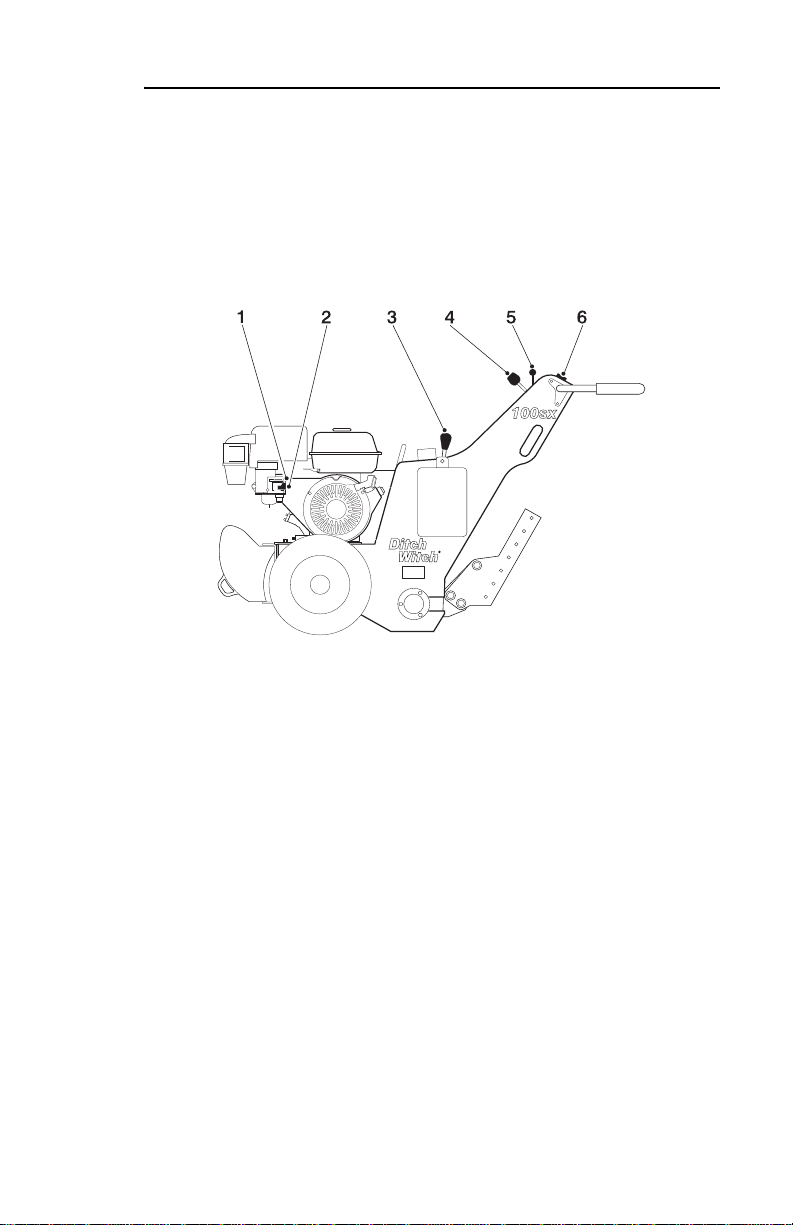
OVERVIEW
CONTROLS
OVERVIEW
om0374h.eps
1. Choke
2. Fuel shutoff valve
3. Plow control
4. Speed/direction control
5. Throttle lever
6. Key switch
Page 10
10 100sx - CONTROLS
CONTROL DESCRIPTIONS
CONTROL DESCRIPTIONS
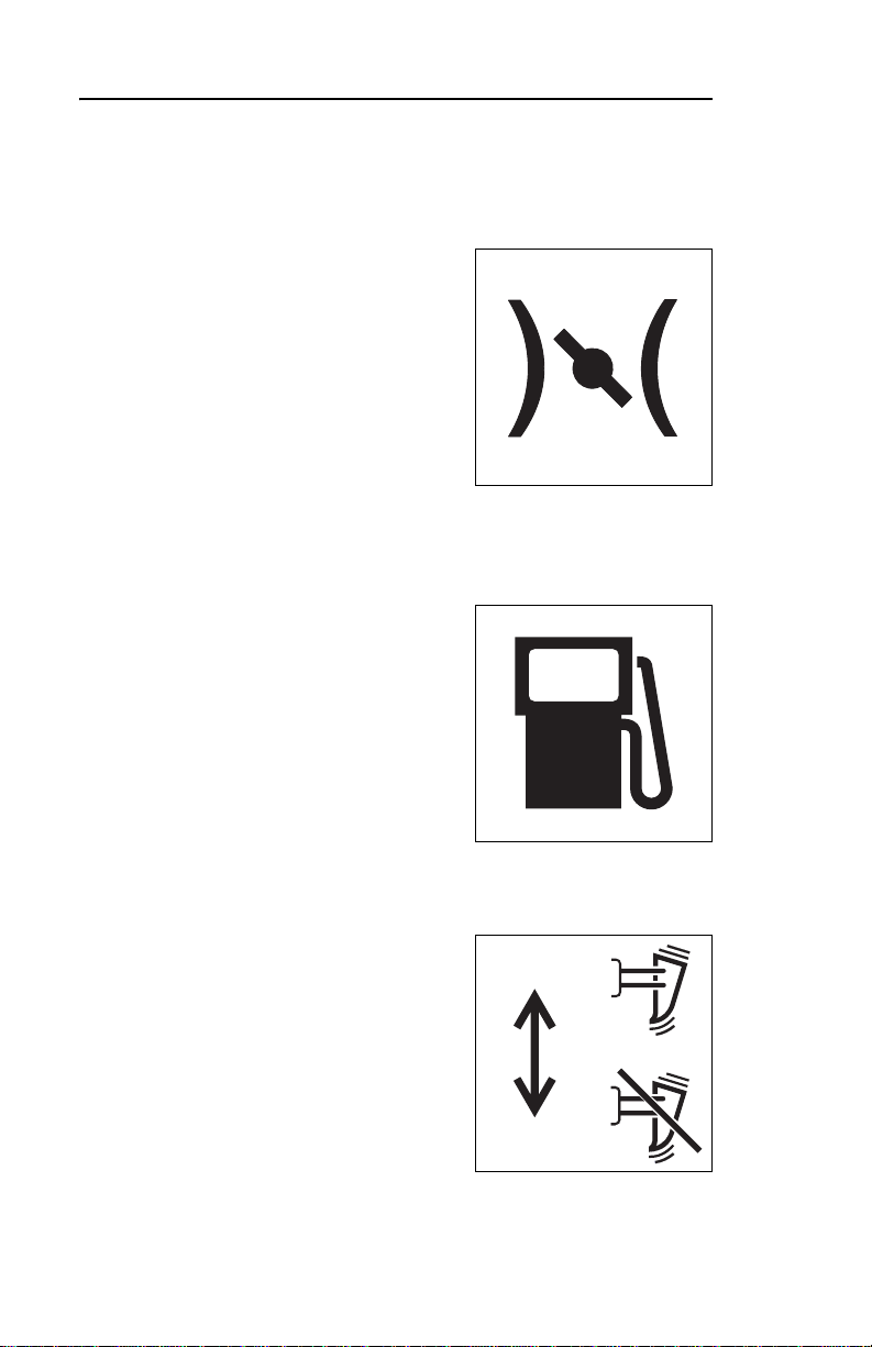
Choke
This control assists in starting cold
engine.
• Push lever forward before
starting.
• Pull lever back after engine is
running.
Fuel Shutoff Valve
Controls fuel flow to engine.
• Open to run machine.
• Close when machine is not
running.
Plow Control
This lever engages and disengages
plow vibrator drive.
• Push forward to engage plow
vibrator.
• Pull backward to disengage
plow vibrator.
Page 11

100sx - CONTROLS 11
CONTROL DESCRIPTIONS
Speed/Direction Control
This lever controls the speed and
direction of the ground drive.
• To travel forward, move lever to
forward position.
• To travel in reverse, move lever
to reverse position. Control
automatically returns to neutral
position if released in reverse
position.
• To go faster in either direction, move control farther from
neutral.
• Move control to neutral position to stop movement.
Throttle Lever
This lever controls engine and
vibrator speed when plow is
engaged.
• Move lever forward to increase
speed.
• Move lever backward to
decrease speed.
Page 12

12 100sx - CONTROLS
CONTROL DESCRIPTIONS
Key Switch
This switch enables engine start.
• Ensure plow control is
disengaged.
• Move speed/direction control to
neutral position.
• Insert key and turn to on position
to enable rope start.
• Turn key to off position to stop engine.
Page 13

100sx - SAFETY 13
CONTROL DESCRIPTIONS
SAFETY
Follow these guidelines before operating any jobsite equipment:
• Complete proper training and read operator’s manual before
using equipment.
• Contact One-Call (811) and any utility companies. Have all
underground lines and cables located and marked before
operating equipment. If you damage a utility, contact utility
company.
• Classify jobsite based on its hazards and use correct
equipment, safety equipment, and work methods for jobsite.
• Mark jobsite clearly and keep spectators away.
• Wear personal protective equipment.
• Review jobsite hazards, safety and emergency procedures,
and individual responsibilities with all personnel before work
begins. Safety videos are available from your Ditch Witch
dealer.
• Replace missing or damaged safety shields and safety signs.
• Use equipment carefully. Stop operation and investigate
anything that does not look or feel right.
• Do not operate unit where flammable gas is present.
• Contact your Ditch Witch dealer if you have any question
about operation, maintenance, or equipment use.
Page 14

14 100sx - SAFETY
UNDERGROUND HAZARDS
UNDERGROUND HAZARDS
Striking underground hazards can cause explosion, electrocution,
fire, and exposure to hazardous materials.
Hazards include:
• Electric cables
• Natural gas lines
• Fiber optic lines
• Water lines
• Sewer lines
• Pipes carrying other chemicals, liquids, or gase s
• Storage tanks
Page 15

100sx - SAFETY 15
EMERGENCY PROCEDURES
EMERGENCY PROCEDURES
If an Electric Line is Damaged
1. DO NOT MOVE. Stay where you are and do not touch any
equipment.
2. Warn others that an electric line has been hit and that they
should stay away.
3. Have someone contact electric company.
4. Do not return to area until given permission by electric
company.
If a Gas Line is Damaged
1. Immediately shut off engine and remove any ignition sources.
2. LEAVE AREA as quickly as possible.
3. Warn others that a gas line h as been hit an d that they should
leave the area.
4. Contact emergency personnel.
5. Contact gas company.
6. Do not return to area until given permission by gas company.
If a Fiber Optic Cable is Damaged
Do not look into cut ends of fiber optic or unidentified cable.
Vision damage can occur.
Page 16

16 100sx - SAFETY
SAFETY ALERT CLASSIFICATIONS
SAFETY ALERT CLASSIFICATIONS
These classifications and the icons defined on the following
pages work together to alert you to situations which could be
harmful to you, jobsite bystanders or your equipment. When you
see these words and icons in the book or on the machine,
carefully read and follow all instructions. YOUR SAFETY IS AT
STAKE.
Watch for the three safety alert levels: DANGER, WARNING and
CAUTION. Learn what each level means.
indicates an imminently hazardous situation
which, if not avoided, will result in death or serious injury.
indicates a potentially hazardous situation which,
if not avoided, could result in death or serious injury.
indicates a potentially hazardous situation which,
if not avoided, may result in minor or moderate injury.
Watch for two other words: NOTICE and IMPORTANT.
NOTICE can keep you from doing something that might damage
the machine or someone's property. It can also to alert against
unsafe practices.
IMPORTANT can help you do a better job or make your job
easier in some way.
Page 17

100sx - SAFETY 17
SAFETY ALERTS
SAFETY ALERTS
Electric shock. Contacting electric
lines will cause death or serious injury. Know
location of lines and stay away.
Deadly gases. Lack of oxygen or
presence of gas will cause sickness or death.
Provide ventilation.
Jobsite hazards
could cause death or serious injury .
Use correct equipment and work
methods. Use and maintain proper
safety equipment.
Crushing weight
could cause death or serious injury .
Use proper procedures and
equipment or stay away.
Moving parts could
cut off hand or foot. Stay away.
Page 18

18 100sx - SAFETY
SAFETY ALERTS
Runaway possible. Machine could
run over you or others. Learn how to use all
controls. Start and operate only from operator’s
position.
Improper control function could
cause death or serious injury. If control does not
work as described in instructions, stop machine
and have it serviced.
Incorrect procedures could result
in death, injury, or property damage. Learn to use
equipment correctly.
NOTICES:
• Unless otherwise instructed, all service should be performed
with engine shut off.
• Refer to engine manufacturer's manual for engine
maintenance instructions.
Page 19

100sx - SAFETY 19
SAFETY ALERTS
Hot parts may cause burns. Do not
touch until cool.
Exposure to high noise levels may
cause hearing loss. Wear hearing protection.
Page 20

20 100sx - SAFETY
Page 21

100sx - OPERATION 21
INSPECT MACHINE
OPERATION
INSPECT MACHINE
Check the following before each day's work. Refer to
LUBRICATION and MAINTENANCE for additional information.
• General appearance.
• Condition of plow blade, drive belts, and air filter.
• Fuel lines and fittings for signs of leakage, wear, or other
damage.
• Tire pressure. Use reliable tire pressure gauge.
• Engine oil level. Keep oil level at highest line on filler cap/
dipstick.
• Fuel level. Fill tank at end of day to reduce condensation.
• Signs are in place and readable.
• Guards and shields are in place.
• Nuts and bolts are tight. Tighten as specified in torque table s
in Parts Manual.
Page 22

22 100sx - OPERATION
START-UP
START-UP
Deadly gases. Lack of oxygen or
presence of gas will cause sickness or death.
Provide ventilation.
Incorrect procedures could result
in death, injury, or property damage. Learn to use
equipment correctly.
IMPORTANT: Read engine manufacturer's starting and
operating instructions. Follow directions for new engine break-in.
1. Disengage plow control by moving lever back.
2. Open fuel shutoff valve.
3. Check that speed/direction control (orange) is in neutral
position.
4. Move throttle to half open.
5. Close choke to start cold engine.
6. Insert key into switch and turn to on position.
Page 23

100sx - OPERATION 23
SHUTDOWN
7. Pull briskly on starter-rope handle at left side of machine.
If engine does not start after three pulls on rope start, turn key
switch to off position and check for fuel blockage or ignition
system problems.
8. Check controls for correct operation.
9. After engine has warmed up, return choke to open position.
Improper control function could
cause death or serious injury. If control does not
work as described in instructions, stop machine
and have it serviced.
EMERGENCY SHUTDOWN: Turn key switch to off position.
SHUTDOWN
1. Move speed/direction contr o l to neutral position.
2. Disengage plow drive by moving plow control lever back.
3. Turn key switch to off position and remove key.
4. Close fuel shutoff valve.
Page 24

24 100sx - OPERATION
DRIVE
DRIVE
Incorrect procedures could result
in death, injury, or property damage. Learn to use
equipment correctly.
NOTICE: Drive slowly and cautiously at all times.
Jobsite hazards
could cause death or serious injury.
Use correct equipment and work
methods. Use and maintain proper
safety equipment.
1. Start with speed/direction control in neutral position.
2. Run engine with throttle at low idle.
3. Slowly engage speed/direction control.
4. Adjust drive speed with speed/direction control.
5. To stop, move speed/direction control to neutral position.
Page 25

100sx - OPERATION 25
ATTACH AND REMOVE BLADE
ATTACH AND REMOVE BLADE
1. Shut off engine, close fuel shutoff valve, and tip machine forward onto weight assembly.
2. Use two blade pins to position blade mounts onto vibrator
arm.
3. When attaching blade mount to vibrator arm, pin top hole
first. Pivot blade mount to align lower vibrator arm hole with
one of lower blade mount holes. Outer hole gives more
vertical angle for normal plowing. Hole nearer plow gives
steeper blade angle for difficult soil conditions.
4. The plow blade can be adjusted up or down in blade mount.
Always install blade pin in lowest hole possible.
5. To remove blade, remove pins holding blade mount to
vibrator arm.
Page 26

26 100sx - OPERATION
PLOW
PLOW
Incorrect procedures could resu lt
in death, injury, or property damage. Learn to use
equipment correctly.
NOTICE: Keep hands on handlebars while
operating plow.
1. Drive to starting point.
2. Follow blade attachment procedure.
3. Feed cable in cable chute or insert material in pulling grip.
4. Open fuel shutoff valve.
5. Tilt machine back onto blade.
6. Start engine and run at high idle.
7. Engage plow control.
8. Lower plow blade to desired depth by pushing down on
handlebars until skid-plate touches ground.
9. Slowly move speed/direction control forward to begin
plowing.
10. To turn, push down on handlebars to break traction and pivot
machine. Concentrate weight on handlebar to outside of turn.
11. When finished plowing, return speed/direction control to
neutral position, lift handlebars to clear blade from ground,
disengage plow control, and and move throttle to low idle.
12. Follow shutdown procedure.
13. Remove cable from cable chute and follow blade removal
procedure.
Page 27

100sx - TRANSPORTATION 27
LIFT
TRANSPORTATION
Crushing weight
could cause death or serious injury.
Use proper procedures and
equipment or stay away.
LIFT
Points
Lifting points are identified by lifting
decals. Lifting at any other point is
unsafe and can damage machinery.
Procedure
Before lifting, check SPECIFICATIONS. Use a crane capable of
supporting the equipment’s size and weight.
om0385h.eps
Page 28

28 100sx - TRANSPORTATION
HAUL
HAUL
Machine can be hauled by trailer, van, or pickup truck. Before
hauling check the following:
• Check that loading ramps will support weight. See
SPECIFICATIONS.
• Check that adequate tiedowns are available.
Jobsite hazards
could cause death or serious injury.
Use correct equipment and work
methods. Use and maintain proper
safety equipment.
NOTICES:
• Park, unload, and load trailer on level part of jobsite.
• To prevent tipping, connect trailer to tow vehicle before
loading or unloading.
Page 29

100sx - TRANSPORTATION 29
LOAD
LOAD
1. Follow blade removal procedure.
2. Start machine following instructions in OPERATION.
3. Move throttle to half open.
EMERGENCY SHUTDOWN: Turn ignition switch to off position.
4. Align machine with ramps or trailer, boom first.
5. Guide machine onto trailer.
6. When tie-down position is reached, move speed/direction
control to neutral position.
7. Chain through loop on weight assembly and tightly attach
chain tie-down points on bed of trailer or vehicle.
For machines with serial numbers below 4R0376, chain
across weight assembly.
8. Move speed/direction contr o l to reve r se po sit i on .
9. Reverse machine to tighten front chain.
10. Follow shutdown procedure in OPERATION.
11. Place chain through slots below control console, attach chain
to tie-down points on bed of trailer or vehicle and tighten
chain with binder.
Page 30

30 100sx - TRANSPORTATION
UNLOAD
UNLOAD
1. Remove tiedowns from machine.
2. Start machine following instructions in OPERATION.
3. Use speed/direction control to slowly back machine o ff tr ailer
or down ramps.
Page 31

100sx - LUBRICATION 31
UNLOAD
LUBRICATION
Proper lubrication and maintenance protects Ditch Witch
equipment from damage and failure. In extreme conditions,
lubricate more frequently.
Use only recommended lubricants. Fill to capacities listed in
SPECIFICATIONS section.
Recommended Lubricants
GEO Gasoline engine oil (see oil temper ature chart for ap propriate SA E weight) mee ting API
MPG Multipurpose grease
THF Tractor hydraulic fluid, similar to Phillips 66 HG, Mobilfluid 423, Chevron Trac tor
CL Chain lubricant
engine service classification SD
Hydraulic Fluid, Texaco TDH Oil, or equivalent
Incorrect procedures could result
in death, injury, or property damage. Learn to use
equipment correctly.
sf1027
NOTICES:
• Unless otherwise instructed, all service should be performed
with engine off.
• Refer to engine manufacturer’s manual for engine
maintenance instructions.
Page 32

32 100sx - LUBRICATION
OVERVIEW
OVERVIEW
om0372h.eps
Interval Task Ref. Lubricant
10 hours Check hydraulic oil 3 THF
Check engine oil 4 GEO
25 hours Lube chain 6 CL
50 hours Change engine oil 4,5 GEO
150 hours Change hydraulic oil and filter 1,2,3 THF
Lube wheel bearings 7 MPG
Page 33

100sx - LUBRICATION 33
HYDRAULIC OIL
HYDRAULIC OIL
Check
Check hydraulic oil at filler/breather
cap every 10 hours. Oil level should
be at bottom of strainer screen
when cool. Add THF if needed.
Change
Change hydraulic oil and filter every
150 hours. Drain oil at plug (2)
located behind the plow mount.
Replace drain plug.
Change hydraulic oil filter (1)
located above drain plug.
Fill to bottom of strainer screen with
THF.
CHAIN
Lube chain every 25 hours with CL.
Access chain through hole in front of engine.
Page 34

34 100sx - LUBRICATION
ENGINE OIL
ENGINE OIL
Check
Check engine oil at filler cap/
dipstick. Oil should be at level
indicated on dipstick. Add GEO if
needed. Consult "Engine Oil
Temperature Chart" for oil
specifications.
Change
Change engine oil every 50 hours.
To drain oil remove drain plug at
front of engine.
Replace drain plug, fill with GEO,
and replace filler cap/dipstick.
Engine Oil Temperature Chart
Page 35

100sx - 35
WHEEL BEARINGS
WHEEL BEARINGS
Lube zerk every 150 hours with
MPG.
Page 36

36 100sx -
WHEEL BEARINGS
Page 37

100sx - MAINTENANCE 37
WHEEL BEARINGS
MAINTENANCE
Proper lubrication and maintenance protects Ditch Witch
equipment from damage and failure. In extreme conditions,
lubricate more frequently.
Incorrect procedures could result
in death, injury, or property damage. Learn to use
equipment correctly.
NOTICES:
• Unless otherwise instructed, all service should be performed
with engine shut off.
• Refer to engine manufacturer’s manual for engine
maintenance instructions.
Page 38

38 100sx - MAINTENANCE
OVERVIEW
OVERVIEW
om0373h.eps
Interval Task Ref.
10 hours Check tires and lugnuts 5,4
25 hours Clean foam air filter element 2
100 hours Change paper air filter element 1
As needed Clean feed chute on plow blade
Adjust belt tension 3
Page 39

100sx - MAINTENANCE 39
TIRES AND LUGNUTS
TIRES AND LUGNUTS
Check tires every 10 hours for proper inflation. Use an accurate
pressure gauge. Maintain air pressure at 15 psi (10.3 kPa).
Tighten lugnuts to 32 ft•lb (43.2 N•m).
For machines with serial numbers below 4R0376, tighten castle
nut firmly, then align castle nut slot with pin hole and insert cotter
pin. If wheel will not turn without binding, loosen nut to next slot
that aligns with hole. Reinstall cotter pin.
AIR FILTER ELEMENTS
Wash foam element (2) ever y 25 hours
in high flashpoint solvent.
NOTICE: Do not use gasoline or low
flashpoint solvent for cleaning. They
are flammable and are explosive under
certain conditions.
Change paper element (1) every 100 hours.
Page 40

40 100sx - MAINTENANCE
BELT TENSION
BELT TENSION
As needed, adjust belt tension by loosening four engine moun ting
bolts. Move engine forward to increase belt tension or backward
to reduce tension.
Page 41

100sx - SPECIFICATIONS 41
BELT TENSION
SPECIFICATIONS
om0376h.eps
DIMENSIONS U.S. METRIC
H1 Operating height 41 in 104 cm
A3’ Angle of departure without blade 50° 50°
L1 Maximum length without reel carrier 70 in 178 cm
L2 Maximum length with reel carrier 86.5 in 220 cm
W1 Plow vehicle width 35 in 89 cm
A’ Maximum depth 13 in 33 cm
A Maximum cover depth 12 in 30 cm
GENERAL
Ditch Witch Model 100SX, self-propelled, non-riding, hydrostatic, two-wheel
drive, vibratory plow. Pull and feed blades available. Ground drive is through
rubber tires.
Page 42

42 100sx - SPECIFICATIONS
BELT TENSION
OPERATION U.S. METRIC
Maximimum crowd speed forward 92 fpm 28 m/min
Maximum crowd speed reverse 92 fpm 28 m/min
Vehicle clearance circle 70 in 178 cm
Plow blade sizes
Pull blades (cover depth x mole diameter) 6-12 x .75 in 152-305 x
19 mm
Feed blades (tube diameter x cover depth (bend
radius)
Operating weight 720 lb 327 kg
Operator orientation: facing front of vehicle
Vibration
ENGINE
Honda GX340 gasoline engine
Cooling medium: air
Number of cylinders: one
Displacement
Bore 3.22 in 82 mm
Stroke 2.52 in 64 mm
Engine manufacturer’s gross power rating @ 3600
rpm
*Maximum governed speed as installed (no load) 3400 rpm 3400 rpm
Flywheel power @ 3400 rpm (full load) 10.2 hp 7.5 kW
Fuel consumption @ 3600 rpm 0.89 gph 3.4 L/h
**Maximum tilt angle 20° 20°
*All warranty is void if engine is run above maximum governed speed as
installed (no load)
.375 x 6-12
(1) in
47.9 ft/s
20.6 in
2
3
9 x 152-305
(25) mm
14.6 m/s
337 cm
11 hp 8.2 kW
2
3
**Exceeding these operating angles will cause engine damage. This DOES
NOT imply machine is stable to maximum angle of safe engine operation.
Page 43

100sx - SPECIFICATIONS 43
BELT TENSION
POWER TRAIN U.S. METRIC
Transmission: Hydrostatic, infinitely variable forward and reverse, 3:1 chain drive from
motor to axle
Tires: 18 x 1 1-8, 3-ply
Drive line system: belts and sheaves
Vibratory mechanism: eccentric shaft
HYDRAULIC SYSTEM
Ground drive pump capacity @ 3600 rpm, relief
2.2 gpm 8.3 L/min
valve setting @ 2,000 psi
Ground drive pump displacement/revolution
Ground drive motor displacement/revolution
.223 in
9.6 in
3
3
.556 cm
157 cm
3
3
Directional control valve type: open center
Delivery capacity 10 gpm 37.8 L/min
System relief valve setting 2500 psi 17 237 kPa
FLUID CAPACITIES
Fuel tank 1.7 gal 6.5 L
Engine oil 2.3 pt 1.1 L
Hydraulic system 3.5 gal 13.2 L
NOISE LEVELS
Operator 92 dBA sound pressure per ISO 6394
Exterior 101 dBA sound power per ISO 6393
VIBRATION LEVELS
Vibration at the operator’s hand during normal operation is x m/s
2
Specifications are general and subject to change without notice. If exact
measurements are required, equipment should be weighed and measured. Due to
selected options, delivered equipment may not necessarily match that shown.
Page 44

44 100sx - SPECIFICATIONS
Page 45

100sx - WARRANTY 45
WARRANTY
Ditch Witch Equipment and Replacement Parts
North American*
Limited Warranty Policy
Major Component Limited Warranty
Major components are warranted for a period of 1000 hours of use or one year,
whichever occurs first, beginning on date of delivery of any such new product. The
Major Component Limited Warranty covers only Major Components listed under
Major Component Limited Warranty that are manufactured and distributed by The
Charles Machine Works, Inc. (“CMW”). Replacement parts and other serial
numbered products (“Products”) that are not listed under Major Component
Limited Warranty, and non-major components are covered under Product Limited
Warranty.
Major Components are defined as:
•Frames.
• Differentials and parts contained within.
• Mechanical transmissions.
• Drive gearboxes and parts contained within.
• Hydraulic, hydrostatic, and fluid pumps, motors and components that control or
protect pumps and motors.
• Auxiliary hydraulic control valves and electrical components used for controlling
hydraulic components.
• Hydraulic cylinders and components excluding repair kits.
• Batteries, alternators, instruments, gauges, and protection components for
electrical systems.
• Pierce Airrow bodies, strikers, and tailpieces.
Free replacement parts and labor will be provided at any authorized dealership for
any part of Major Component which has a defect in material or workmanship
within warranty period. Defects will be determined by an inspection of major
component or part by CMW or its authorized dealer. The product containing a
major component or part must be presented to CMW or its authorized dealer for
inspection within 30 days of the date major component or part fails. CMW will
provide the location of its inspection facilities or its nearest authorized dealer upon
inquiry. CMW reserves the right to supply remanufactured replacement parts as it
deems appropriate.
* Equipment owners in countries other than U.S., Canada, Mexico, and Puerto
Rico should refer to Ditch Witch International Warranty Policy.
Page 46

46 100sx - WARRANTY
Product Limited Warranty
Products are warranted for 90 days from date of delivery of any new product. Free
replacement parts and labor will be provided at any authorized dealership for any
product which has a defect in material or workmanship within warranty period.
Replacement parts are warranted for 90 days from date of delivery of any such
replacement part. Any part of a product subject to ground contact is warranted
only for defects in material or workmanship and only for the period of operational
life of such part, which period shall not in any event exceed 90 days. Defects will
be determined by an inspection of the product or part by CMW or its authorized
dealer. The product or part must be presented to CMW or its authorized dealer for
inspection within 30 days of the date of failure. CMW will provide the location of its
inspection facilities or its nearest authorized dealer upon inquiry. CMW reserves
the right to supply remanufactured replacement parts as it deems appropriate.
Page 47

100sx - WARRANTY 47
Exclusions
from Major Component and Product Limited Warranty
Specifically excluded from Major Component and Product Limited Warranty are:
• Transportation charges related to repair, replacement, or inspection of
products, major components, or parts.
• Parts subject to ground contact (including but not limited to drill pipe, downhole
tools, digging chain, teeth and sprockets).
• All incidental or consequential damages.
• All defects, damages, or injuries caused by misuse, abuse, improper
installation, alteration, neglect, or uses other than those for which products
were intended.
• All defects, damages, or injuries caused by improper training, operation, or
servicing of products in a manner inconsistent with manufacturer’s
recommendations.
• All engines and engine accessories (these are covered by original
manufacturer’s warranty).
• Parts which may be subject to another manufacturer’s warranty (such warranty
will be available to purchaser).
• All implied warranties not expressly stated herein, including any warranty of
fitness for a particular purpose and merchantability.
IF THE PRODUCTS ARE PURCHASED FOR COMMERCIAL PURPOSES AS
DEFINED BY THE UNIFORM COMMERCIAL CODE, THEN THERE ARE NO
WARRANTIES WHICH EXTEND BEYOND THE FACE HEREOF AND THERE
ARE NO IMPLIED WARRANTIES OF ANY KIND WHICH EXTEND TO A
COMMERCIAL BUYER. ALL OTHER PROVISIONS OF THIS LIMITED
WARRANTY APPLY INCLUDING THE DUTIES IMPOSED.
Ditch Witch products have been tested to deliver acceptable performance in most
conditions. This does not imply they will deliver acceptable performance in all
conditions. Therefore, to assure suitability, products should be operated under
anticipated working conditions prior to purchase.
This limited warranty applies to the owner of the product. Some states do not
allow exclusion or limitation of incidental or consequential damages, so above
limitation of exclusion may not apply. Further, some states do not allow exclusion
of or limitation of how long an implied warranty lasts, so the above limitation may
not apply. This limited warranty gives owner specific legal rights and the owner
may also have other rights which vary from state to state.
Page 48

48 100sx - WARRANTY
For information regarding this limited warranty, contact CMW’s Product Support
department, P.O. Box 66, Perry, OK 73077-0066, or contact your local Ditch Witch
dealer.
First version: 1/91; Latest revision: 4/99
Page 49

Page 50

 Loading...