

Page 1

Page 2
WARNING
FOR YOUR PROTECTION, PLEASE READ THE
FOLLOWING:
Water and Moisture: Appliance should not be used near water (e.g. near a
bathtub, washbowl, kitchen sink, laundry tub, in a wet basement, or near a
swimming pool, etc). Care should be taken so that objects do not fall and liquids are not spilled into the enclosure through openings.
POWER SOURCES: The appliance should be connected to a power supply
only of the type described in the operating instructions or as marked on the
appliance.
GROUNDING OR POLARIZATION: Precautions should be taken so that the
grounding or polarization means of an appliance is not defeated.
POWER CORD PROTECTION: Power supply cords should be routed so that
they are not likely to be walked on or pinched by items placed upon or against
them, paying particular attention to cords at plugs, convenience receptacles,
and the point where they exit from the appliance.
SERVICING: To reduce the risk of fire or electric shock, the user should not
attempt to service the appliance beyond that described in the operating instructions. All other servicing should be referred to qualified service personnel.
CAUTION: To reduce the risk of fire replace only with same type fuse.
ATTENTION: Utiliser un fusible de recharge de même type.
CAUTION: To reduce the risk of fire replace LAMPwith manufacturers recommended part ( Refer to service literature)
U.K. MAINS PLUG WARNING
A moulded mains plug that has been cut off from the cord is unsafe. Discard
the mains plug at a suitable disposal facility. NEVER UNDER ANY CIRCUMSTANCES SHOULD YOU INSERTA DAMAGED OR CUT MAINS
PLUG INTO A13 AMP POWER SOCKET. Do not use the mains plug without the fuse cover in place. Replacement fuse covers can be obtained from
your local retailer. Replacement fuses are 13 amps and MUST be ASTA
approved to BS1362.
The symbols shown above are internationally accepted symbols that warn of
potential hazards with electrical products. The lightning flash with arrowpoint
in an equilateral triangle means that there are dangerous voltages present within the unit. The exclamation point in an equilateral triangle indicates that it is
necessary for the user to refer to the owner’s manual.
These symbols warn that there are no user serviceable parts inside the unit.
Do not open the unit. Do not attempt to service the unit yourself. Refer all
servicing to qualified personnel. Opening the chassis for any reason will void
the manufacturer’s warranty. Do not get the unit wet. If liquid is spilled on
the unit, shut it off immediately and take it to a dealer for service. Disconnect
the unit during storms to prevent damage.
ELECTROMAGNETIC
COMPATIBILITY
This unit conforms to the Product Specifications noted on the Declaration of
Conformity. Operation is subject to the following two conditions:
• this device may not cause harmful interference, and
• this device must accept any interference received, including
interference that may cause undesired operation. Operation of
this unit within significant electromagnetic fields should be
avoided.
• use only shielded interconnecting cables.
FCC COMPLIANCE
This equipment has been tested and found to comply with the limits for a Class
B digital device, pursuant to Part 15 of the FCC Rules. These limits are
designed to provide reasonable protection against harmful interference in a residential installation. This equipment generates, uses and can radiate radio frequency energy and, if not installed and used in acordance with the instructions,
may cause harmful interference to radio communications. However, there is no
guarantee that interference will not occur in a particular installation. If this
equipment does cause harmful interference to radio or television reception,
which can be determined by turning the equipment off and on, the user is
encouraged to try to correct the interference by one or more of the following
measures:
• Reorient or relocate the receiving antenna
• Increase the separation between the equipment and receiver that may cause
undesired operation.
• Connect the equipment into an outlet on a circuit different from that to which
the receiver is connected
• Consult the dealer or an experienced radio/TV technician for help.
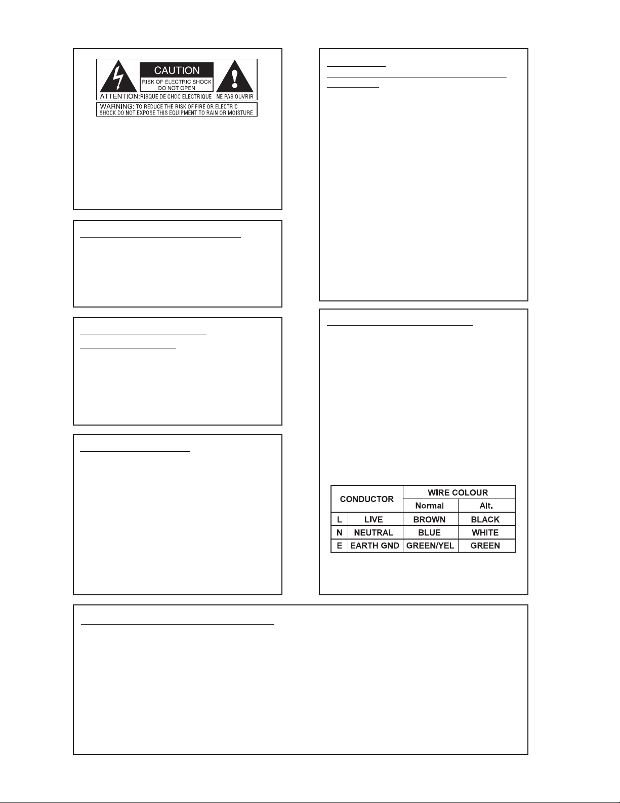
SAFETY INSTRUCTIONS
Notice For Customers If Your Unit Is Equipped With A Power Cord.
WARNING:THISAPPLIANCEMUSTBEEARTHED.
The cores in the mains lead are coloured in accordance with the following
code:
GREEN and YELLOW - Earth BLUE - Neutral BROWN - Live
As colours of the cores in the mains lead of this appliance may not correspond
with the coloured markings identifying the terminals in your plug, proceed as
follows:
• The core which is coloured green and yellow must be connected to the terminal in the plug marked with the letter E, or
with the earth symbol, or coloured green, or green and yellow.
• The core which is coloured blue must be connected to the terminal marked N or coloured black.
• The core which is coloured brown must be connected to the
terminal marked L or coloured red.
This equipment may require the use of a different line cord, attachment plug,
or both, depending on the available power source at installation. Connect this
equipment only to the power source indicated on the equipment rear panel. If
the attachment plug needs to be changed, refer servicing to qualified service
personnel who should refer to the table below. The green/yellow wire shall be
connected directly to the unit's chassis.
WARNING: If the ground is defeated, certain fault conditions in the unit or in
the system to which it is connected can result in full line voltage between
chassis and earth ground. Severe injury or death can then result if the chassis
and earth ground are touched simultaneously.
DECLARATION OF CONFORMITY
Manufacturer’s Name: IVL Technologies Ltd.
per DigiTech specifications
Manufacturer’s Address: #108-721 Vanalman Ave
Victoria, B.C.
Canada V8Z 3B6
declares that the products:
DigiTech VTP-1 Dual Vacuum Tube Preamp
conform to the following product specifications:
EMC: EN 55022 (1987):
CISPR 22 (1993) Class B
EN 50082-1 (1992)
Supplementary Information:
The product herewith complies with the requirements of the Low Voltage Directive
73/23/EEC and the EMC Directive 89/336/EEC (1989) as ammended by the CE
Marking Directive 93/68/EEC (1993).
IVL Technologies Ltd.
#108-721 Vanalman Ave.
Victoria, B.C.
Canada V8Z 3B6
March 4, 1996Peter George
Vice President of Engineering
European Contact: Your local DigiTech Sales and Service Office or
International Sales Office
3 Overlook Drive Unit #4
Amherst, New Hampshire 03031, USA Tel (603) 672-4244 Fax (603) 672 4246
Safety: EN 60065
IEC 65 (1993)
Amendment 1 (1987)
Amendment 2 (1989)
Amendment 3 (1992)
Page 3

Digitech VTP-1 Owner’s Manual
Table of Contents
Introduction
.................................................................................1
Warranty......................................................................................2
Connection Examples...........................................................3
Rear Panel.................................................................................4
Wiring Scheme..........................................................................4
Mic Input...................................................................................4
Line Inputs.................................................................................4
Insert Loop ................................................................................5
Send...........................................................................................5
Return ........................................................................................5
Digital Outputs ..........................................................................5
Front Panel.................................................................................6
Post Trim...................................................................................6
Pre Gain.....................................................................................6
The VU Meter and CLIP LED..................................................7
The EQ section..........................................................................7
EQ In/Out switch.......................................................................8
Lo Cut switch ............................................................................8
Mic/Line Input switch...............................................................8
Phase Reverse switch ................................................................9
20 dB Pad ..................................................................................9
+48V phantom power switch ....................................................9
DIGITAL OUTPUT Section .....................................................9
FORMAT Switch ................................................................9
SAMPLE RATE Switch .....................................................9
Appendix
Signal Flow Diagram .................................................................i
Specifications ............................................................................ii
Page 4

Introduction
Thank you for purchasing the Digitech VTP-1 vacuum tube preamplifier. This product was developed to help you improve the sound of your digital recording, analog recording, and live performance.
The VTP-1 offers a better alternative to using the average quality microphone preamps found in the
typical multi-input console. For economic reasons, these console preamps are typically of lower
quality than a single, dedicated unit. You can use the VTP-1 to get your basic tracks sounding great
and then you can run the finished mix through it for final “tube” treatment and equalization.
The VTP-1’s preamplifier circuit is a hybrid design consisting of a high-voltage class Avacuum tube
amplification stage, coupled with an ultralow noise, low distortion solid-state driver stage. In the
VTP-1’s base configuration, the solid-state driver stage provides 40 dB of gain to the microphone
inputs. With the optional input transformers installed, the driver stage gain is reduced to 20 dB,
with 20 dB of virtually “noiseless” self-gain provided by the transformers.
Please contact DOD Electronics at 801-566-8800 to order the transformer installation
instructions and parts kit.
The vacuum tube amplification stage is a classic, high plate-voltage design utilizing a pure class A
topology. Aparallel-triode arrangement is employed, in addition to a fully-regulated 235V plate
supply to maximize signal-to-noise performance and transient response. Only premium-grade
12AX7A vacuum tubes are used in the VTP-1 which are hand-tested and graded specifically for the
VTP-1 by Audio Glassic in the USA.
Precision 1% metal-film resistors are used throughout the audio path to ensure performance stability
and low noise. In addition to precision resistors, all filter and equalization circuits utilize high quality plastic-film capacitors to maintain spectral accuracy and minimize the long-term effects of component drift. To ensure years of trouble-free operation, each VTP-1 must pass a rigorous set of performance tests and a 24-hour burn-in period before it is shipped from the factory
Features
• Low noise, pure Class Avacuum tube preamplifier stage
• Line level input that accepts -10 dBv and +4 dBu signals
• Single vacuum tube per channel with adjustable gain and trim controls
• Four band semi-parametric equalization with EQ bypass switch
• 75 Hz low cut filter with steep 12 dB/octave
• 18 bit digital output to AES/EBU and S/PDIF digital protocols
• XLR and TRS 1/4” balanced analog inputs and outputs
• Post EQ insert loop
• Combined VU metering and multisource peak indication
• Switches for 48 volt phantom power, phase reversal, 20 dB gain pad and input select
•••
1 •••
Page 5

Warranty
1. The warranty registration card must be mailed within ten days after purchase date to validate the
warranty.
2. DigiTech warrants this product, when used solely within the U.S., to be free from defects in
materials and workmanship under normal use and service.
3. DigiTech liability under this warranty is limited to repairing or replacing defective materials that
show evidence of defect, provided the product is returned to DigiTech WITH RETURN
AUTHORIZATION, where all parts and labor will be covered up to a period of one year. A
Return Authorization number may be obtained from DigiTech by telephone. The company shall
not be liable for any consequential damage as a result of the product’s use in any circuit or
assembly.
4. Proof-of-purchase is considered to be the burden of the consumer.
5. DigiTech reserves the right to make changes in design, and make additions or improvements to
this product without incurring any obligation to install the same on products previously manufactured.
6. The foregoing is in lieu of all other warranties, expressed or implied, and DigiTech neither
assumes nor authorizes any person to assume any obligation or liability in connection with the
sale of this product. In no event shall DigiTech or its dealers be liable for special or consequential
damages, or from any delay in the performance of this warranty due to causes beyond their control.
DigiTech™ and VTP-1 are registered trademarks of DOD Electronics Corporation.
IMPORTANT:
The information contained in this manual is subject to change at any time without notification.
Some information in this manual may also be inaccurate due to undocumented changes in the product or operating system since this version of the manual was completed. The information contained
in this version of the manual supersedes all previous versions.
•••
2 •••
Page 6

Connection Examples
The following diagrams show a few of the ways in which the VTP-1 can be used. Please note that
not all digital recorders have direct digital interfacing via AES/EBU and S/PDIF. These may require
a translator box.
••• 3 •••
As a microphone preamplifier direct to DAT
To add “Tube Warmth” to your mixes
For instrument recording
Page 7

REAR PANEL
WIRING SCHEME
All of the input and output connectors are “pin 2 hot” meaning that pin number 2 on the XLR
connecting cables carries the positive side of the balanced signal. Pin number 3 is “cold”, carrying
the negative polarity and pin 1 is the shield.
The 1/4” TRS (Tip/Ring/Sleeve) jacks are wired so that when you use 3 conductor cables and balanced signals, the tip is hot, the ring is cold and the sleeve is the shield. The 1/4” jacks can also
be used with 2 conductor unbalanced cables. In this case, the tip is hot and the ring and sleeve are
grounded.
MIC INPUT
Connect the cable from your microphone here. If your mic requires phantom power, ensure that
the phantom power switch on the front panel is turned off before connecting your mic. Flip the
front panel Input Select switch to Mic to activate this input.
LINE INPUTS
There are two line inputs to allow you to run a variety of connecting cables from your line level
sources. The XLR connector on the top is a balanced input capable of receiving +4 dBu or -10
dBv signals. The input level sensitivity is adjusted with the PRE GAIN control.
The 1/4” phone connector on the bottom is also a balanced +4/-10 input using the TRS connecting
scheme. This requires a cable with “stereo” phone jacks to be used as a balanced input. It can also
be used with an unbalanced source using a standard two conductor cable. If you plug a connector
into the phone jack input, this will override anything plugged into the XLR input.
••• 4 •••
Page 8

INSERT LOOP
These connectors allow you to insert another processor such as a compressor or de-esser into the
signal path. You would insert the processor into this loop to place it in the path leading to the digital output of the VTP-1. Both the SEND and RETURN are balanced TRS jacks with +4 dBu nominal sensitivity.
SEND
The audio signal produced at the SEND output is taken from a point in the circuit after the VTP1’s tube and EQ stages. You can run a cable from this jack to the input of the external processor.
Inserting a jack here will not interrupt the analog or digital audio output. This is to allow the
SEND to be used as a direct post-preamp output that bypasses the main output stage of the VTP-1.
RETURN
Connect the output of the external processor back to the VTP-1 through this jack. An audio signal
returning here is passed along to both the analog and digital outputs.
DIGITAL OUTPUTS
The VTP-1’s digital output allows you to connect directly to a DAT recorder or digital multitrack
via their digital input. You can completely bypass your mixing console when recording a voice or
instrument through the VTP-1. By connecting a microphone or line level instrument to the input
of the VTP-1, then from the digital output directly to your recorder you keep the signal path as
pure as possible. If you have digital effects in your system and digital mixdown, your audio signal
will only have to be converted back to analog when it’s finally played on a CD player in someone’s home.
The VTP-1’s digital output is offered in two standard stereo formats: AES/EBU and
S/PDIF. Channel 1 of the VTP-1 drives the digital left output and Channel 2 drives digital
right. You have a choice of 44.1 kHz or 48 kHz sampling rates. The controls to select
Format and Sample Rate are on the front panel of the unit. (See the discussion of front
panel controls for more details.)
•••
5 •••
Page 9

Front Panel
POST TRIM Control
This control determines the output level presented at the analog and digital outputs. This and the
PRE GAIN control work together to allow you to dial in the amount of tube saturation you would
like while maintaining a nominal output level.
NOTE: The POST TRIM control should generally be set to the fully clockwise position
unless you want tube saturation.
A reduction in POST TRIM level will reduce the amount of VU meter deflection.
The POST TRIM is an attenuator-type control in that it does not add gain when it is turned all the
way up. Bring up the PRE GAIN control until the meter needle deflects with no clips registering
on the CLIP LED.
You’ll want to reduce the output level with the POST TRIM control when the analog output of the
VTP-1 is connected to a semi pro mixer or recorder with -10dB input sensitivity. The output level
should be reduced because the VTP-1 has sufficient output level to cause distortion.
PRE GAIN Control
This determines the amount of gain the tube amplifier will apply to the input signal. It is also used
to adjust the input sensitivity to -10 dbv and +4 dBu signals. There is up to 66dB of gain available
to amplify even the weakest of microphone signals and up to 26 dB for the line inputs. As you
increase this gain control you will increase the amount of tube saturation that, in moderate
amounts, enhances pleasant, even-order harmonics, but in greater amounts, can cause audible distortion.
If you have the PRE GAIN control set to a level causing tube saturation, you will need to bring
the POST TRIM level down so as not to overdrive the outputs.
••• 6 •••
Page 10

The VU Meter and CLIP LED
These two components give you a combined and highly accurate reading of the amount of level at
the analog and digital outputs. The VU meter is calibrated in Volume Units which give an average
signal level reading. The key word here is “average” because VU meters show the average difference between the peaks and valleys in the level of the program material. While VU meters generally show an accurate level for a synthesizer pad sound where the dynamic differences are slight,
they will let brief peaks through that don’t register on the needle such as those from an energetic
Bass guitar track.
The CLIP LED is a fast-acting indicator to warn you of peaks that are causing audible distortion
at the output stage. It will light when you are 6 dB before the onset of clipping in the analog output and 3 dB before clipping in the digital output. Because there are several stages in the VTP-1,
each with their own input and output, the CLIP LED has sensing at each stage to help you gauge
your levels more accurately.
The EQ section
The EQ section is a high quality solid state equalization circuit that offers you creative and problem-solving control of your input signal. There are two shelving bands and two semi-parametric
bands.
The 80 Hz and 12 kHz have a maximum boost or cut of 15 dB at their respective knee frequencies. The following graphs show the equalization curves at of the 80 Hz and 12 kHz bands at various cut and boost settings.
The LO MID and HI MID are variable bandpass filters which allow control of specific frequency
bands. The “Q” or width of the frequency band is fixed. These filters also have a maximum boost
or cut of 15 dB at their specified center frequency. The following graphs illustrate the Lo Mid and
Hi Mid equalization curves at various cut, boost and center frequency settings.
••• 7 •••
80 Hz Shelving EQ plot
12 kHz Shelving EQ plot
Page 11

••• 8 •••
Boosting frequencies adds gain and you may find that this lights the CLIP LED. If this
occurs, reduce the level with the PRE GAIN control or POST TRIM.
EQ In/Out switch
This switch removes the entire EQ circuit from the signal path. This is useful if you want to confirm that your EQ modifications are an improvement on the non-EQ’d signal. If you are not planning on using the EQ, this switch should be left in the “Out” position.
LO-CUT switch
This switch places a steep 12 dB per octave shelving circuit in the signal path with a knee frequency of 75 Hz. The LO-CUT filter can be engaged independently of the EQ In/Out switch. This is
useful for removing rumble from a microphone input signal. It is also good for reducing the very
low frequency harmonics in signals that cause a muddy low end or sap amplifier power unnecessarily. The following graphic shows the frequency response of the VTP-1 with the LO-CUT filter
in and out.
Mic/Line INPUT switch
This activates either the Microphone or Line input.
LO MID EQ plot
HI MID EQ plot
Lo Cut Filter Plot
Lo Cut “Out”
Lo Cut “In”
Page 12

PHASE reversal switch
You can invert the phase of the incoming signal. This may be required when you have two mics
coming into both channels of the VTP-1 and the distance between the mics is at a critical point
where they cause frequency cancellation. Flipping the phase of one of the input channels can
overcome the notchy, comb filtering effects caused by multiple mics on a single source.
20 dB PAD switch
This inserts a gain reduction circuit into the signal path from the microphone input. The pad is
inserted before the signal is passed on to the tube and it is used to prevent overload distortion
from high output microphones.
+48V phantom power switch
This switch activates phantom power for condenser microphones on pins 2 and 3 of the XLR mic
input. Connect your microphone to the VTP-1 before turning on the phantom power. This will
prevent high voltage arcing that may damage your mic.
WARNING: Do not connect unbalanced sources to this input. The voltage on these pins
is sufficient to cause damage if connected directly to a transducer.
DIGITAL OUTPUT Section
FORMAT Switch
The FORMAT switch selects between the industry-standard AES/EBU and S/PDIF stereo digital audio formats. You should set this switch to the same format as the one your receiving
device requires.
SAMPLE RATE Switch
When using the digital output, the VTP-1 becomes the master clock device and as such, determines the clock frequency (sample rate) for any digital devices connected to it. You have the
choice of 44.1 kHz which is the standard for Compact Disc duplication, and 48 kHz, which is
the sample rate for many DAT machines. If your recorder allows you an option, you are better
off to stay with 44.1 kHz if your recording stands any chance of being duplicated on CD. If
you have recorded a project at 48 kHz and will be putting it out on CD, you will require sample rate conversion that may effect the sound of your recording.
Your recorder should automatically sense any change in sample rate even when no audio is
present. If it doesn’t, you will have to set it manually. You must also ensure that your recorder
is set to synchronize its sample rate to an external digital device.
•••
9 •••
Page 13

••• i •••
+48V Phantom
Power
-20 dB
Optional Input
Transformer
2
2
2
3
3
3
3
2
1
1
1
1
Mic In
(XLR)
Line In
(1/4" TRS)
Line In
(XLR)
Mic/Line
Select
Pre Gain
-1
Phase
Invert
+235 V
+5 V +5 V
Post Trim
Class A
Tube Gain Stage
80 Hz
Shelving
Lo Mid
Sweep
Hi Mid
Sweep
18 Bit
A/D Converter
Trans-
mitter
12 kHz
Shelving
Lo Cut
Filter
EQ
In/Out
Return
Send
VU
Meter
Line Out
(XLR)
Line Out
(TRS 1/4")
∆Σ
Sample
Rate
Format
AES/EBU
S/PDIF
Equalizer
Digital Output
Pad
Clip
Monitor
Clip
Monitor
Clip
Monitor
Clip
Monitor
Clip
Monitor
Clip
Monitor
Clip
Monitor
Clip
Monitor
DIGITECH VTP-1 SIGNAL FLOW DIAGRAM
Page 14

VTP-1 SPECIFICATIONS
Equivalent Input Noise: -127 dBu @ 150Ω
Signal-to-Noise Ratio: > 102 dB, Aweighted
Total Harmonic Distortion + Noise: < 0.1% typical, user-variable
Frequency Response: +0, -1 dB from 20 Hz to 20 kHz
+0, -3 dB from 15 Hz to 40 kHz
Equalization: +/- 15 dB @ 80 Hz (shelving)
+/- 15 dB @ 50 Hz to 3.2 kHz
+/- 15 dB @ 500 Hz to 18 kHz
+/- 15 dB @ 12 kHz (shelving)
Lo-cut Filter: -12 dB/octave @ 75 Hz
Input Impedance: microphone inputs:
standard: 10kΩ
with transformer option: 1.5kΩ
line inputs: 20kΩ
Output Impedance: XLR: < 200Ω
1/4” TRS: < 1kΩ
Maximum Gain: microphone inputs: +66 dB
line inputs: +26 dB
Maximum Input Level: microphone inputs:
pad out: -22 dBu
pad in: -2 dBu
line inputs: +19 dBu
Nominal Output Level: balanced: +12 dBu
unbalanced: +6 dBu
Maximum Output Level: balanced: +23 dBu
unbalanced: +17 dBu
Digital Output: format: AES/EBU or S/PDIF
sampling rate: 44.1 or 48 kHz
Power Requirements: 120 V AC, 50/60 Hz, 30 W
or as specified on rear panel
Fuse: 315 mA, slo-blo
Lamp bulb: Manufacturer: Shogyo P/N: 7152
5 VDC @ 115 mA0.15 Candle Power
Dimensions: 48 cm W x 8.9 cm H x 14.6 cm D
(19” W x 3.5” H x 5.75” D)
Weight: 3.6 kg (8 lbs.)
Specifications subject to change without notice
••• ii •••
Page 15

8760 South Sandy Parkway
Sandy, Utah, 84070
Telephone (801) 566-8800
FAX (801) 566-7005
International Distribution: 3 Overlook Dr Unit 4
Amherst, New Hampshire 03031 U.S.A.
FAX (603) 672-4246
DigiTech™ and VTP-1 are registered trademarks
of DOD Electronics Corporation
Copyright © 1995
IVL Technologies Ltd.
Printed In U.S.A. 6/96
Manufactured in the U.S.A.
VTP-1 18-2158-B
 Loading...