

Page 1
Vocal Harmony and
Effects Processor
Owner’s
Manual
1
Page 2
WARNING FOR YOUR PROTECTION
PLEASE READ THE FOLLOWING:
KEEP THESE INSTRUCTIONS
HEED ALL WARNINGS
FOLLOW ALL INSTRUCTIONS
THE APPARATUS SHALL NOT bE ExPOSED TO DRIPPING OR SPLASHING LIqUID
AND NO ObjECT FILLED WITH LIqUID, SUCH AS vASES, SHALL bE PLACED ON
THE APPARATUS
CLEAN ONLY WITH A DRY CLOTH.
DO NOT bLOCK ANY OF THE vENTILATION OPENINGS. INSTALL IN ACCORDANCE
WITH THE MANUFACTURER’S INSTRUCTIONS.
DO NOT INSTALL NEAR ANY HEAT SOURCES SUCH AS RADIATORS, HEAT REGISTERS,
STOvES, OR OTHER APPARATUS (INCLUDING AMPLIFIERS) THAT PRODUCE HEAT.
ONLY USE ATTACHMENTS/ACCESSORIES SPECIFIED bY THE MANUFACTURER.
UNPLUG THIS APPARATUS DURING LIGHTNING STORMS OR WHEN UNUSED FOR
LONG PERIODS OF TIME.
Do not defeat the safety purpose of the polarized or grounding-type plug. A polarized
plug has two blades with one wider than the other. A grounding type plug has two
blades and a third grounding prong. The wide blade or third prong are provided for your
safety. If the provided plug does not fit your outlet, consult an electrician for replacement
of the obsolete outlet.
Protect the power cord from being walked on or pinched particularly at plugs, convenience receptacles, and the point where they exit from the apparatus.
Refer all servicing to to qualified service personnel. Servicing is required when the apparatus has been damaged in any way, such as power-supply cord or plug is damaged,
liquid has been spilled or objects have fallen into the apparatus, the apparatus has been
exposed to rain or moisture, does not operate normally, or has been dropped.
MAINS DISCONNECT: The plug shall remain readily operable. For rack-mount or installation where plug is not accessible, an all-pole mains switch with a contact separation
of at least 3 mm in each pole shall be incorporated into the electrical installation of
the rack or building.
Manufacturer’s Name: DigiTech
Manufacturer’s Address: 8760 S. Sandy Parkway
Sandy, Utah 84070, USA
declares that the product:
Product name: VOCALIST VL3D
Product option: all (requires Class II power adapter that conforms to the requirements of
EN60065, EN60742, or equivalent.)
conforms to the following Product Specifications:
Safety: IEC 60065 (7th ed. 2001)
EMC: EN 55103 (2001-A1)
EN 55020 (1998)
Supplementary Information:
The product herewith complies with the requirements of the Low Voltage Directive 2006/95/EC and the EMC Directive
2004/108/EC as amended by Directive 93/68/EEC.
Vice-President of Engineering
8760 S. Sandy Parkway
Sandy, Utah 84070, USA
Date: March 20, 2009
European Contact: Your local DigiTech Sales and Service Office or
Harman Music Group
8760 South Sandy Parkway
Sandy, Utah 84070 USA
Ph: (801) 568-8800
Fax: (801) 568-7583
Page 3

Table of Contents
Overview .....................................................................................................1
Introduction ................................................................................................................................................................... 1
musIQ® Technology ....................................................................................................................................................... 1
Front Panel .................................................................................................3
Using the VL3D with a Keyboard ..............................................................9
Using the VL3D with a Guitar ...................................................................10
Guitar Sensitivity ........................................................................................................................................................... 11
Tuner ................................................................................................................................................................................ 11
Using the VL3D with a Computer ............................................................12
Pre-Effects ...................................................................................................14
Warmth ........................................................................................................................................................................... 14
Compressor ................................................................................................................................................................... 14
De Esser .......................................................................................................................................................................... 14
Noise Gate ..................................................................................................................................................................... 14
Pitch Correct ..............................................................................................15
Reverb .........................................................................................................15
Harmony Patches and Parts .....................................................................16
Store and Recall a Patch .............................................................................................................................................. 16
Harmony A/B Parts ....................................................................................................................................................... 16
Harmony Modes .........................................................................................17
musIQ® Harmony Mode ..............................................................................................................................................17
Acappella Harmony Mode .......................................................................................................................................... 17
Notes Harmony Mode................................................................................................................................................. 18
Harmony Voicing ........................................................................................18
Harmony Gender .......................................................................................19
Harmony Mix ..............................................................................................19
Humanize ....................................................................................................19
Harmony On/Off ........................................................................................19
MIDI Configuration ....................................................................................20
MIDI Channel ................................................................................................................................................................. 20
Split Point ........................................................................................................................................................................ 20
1-Channel and 4-Channel MIDI Mode ..................................................................................................................... 21
CC MIDI Channel ......................................................................................................................................................... 21
Program Change ............................................................................................................................................................ 22
Saving Global Parameters ............................................................................................................................................22
External Footswitch ...................................................................................22
MIDI Messages ............................................................................................23
Notes ............................................................................................................................................................................... 23
Program Change ............................................................................................................................................................ 23
System Exclusive............................................................................................................................................................ 23
Factory Reset ..............................................................................................24
Continuous Controller...............................................................................24
Effects Block Diagram ...............................................................................25
Specifications ..............................................................................................26
Page 4

Warranty
We at DigiTech® are very proud of our products and back up each one we sell with the following
warranty:
1. The warranty registration card must be mailed within ten days after purchase date to validate this
warranty.
2. DigiTech warrants this product, when used solely within the U.S., to be free from defects in materials and
workmanship under normal use and service.
3. DigiTech liability under this warranty is limited to repairing or replacing defective materials that show
evidence of defect, provided the product is returned to DigiTech WITH RETURN AUTHORIZATION,
where all parts and labor will be covered up to a period of one year. A Return Authorization number may
be obtained from DigiTech by telephone. The company shall not be liable for any consequential damage as
a result of the product’s use in any circuit or assembly.
4. Proof-of-purchase is considered to be the burden of the consumer.
5. DigiTech reserves the right to make changes in design, or make additions to, or improvements upon this
product without incurring any obligation to install the same on products previously manufactured.
6. The consumer forfeits the benefits of this warranty if the product’s main assembly is opened and tampered with by anyone other than a certified DigiTech technician or, if the product is used with AC voltages
outside of the range suggested by the manufacturer.
7. The foregoing is in lieu of all other warranties, expressed or implied, and DigiTech neither assumes nor
authorizes any person to assume any obligation or liability in connection with the sale of this product. In
no event shall DigiTech or its dealers be liable for special or consequential damages or from any delay in
the performance of this warranty due to causes beyond their control.
NOTE: The information contained in this manual is subject to change at any time without notification. Some
information contained in this manual may also be inaccurate due to undocumented changes in the product
or operating system since this version of the manual was completed. The information contained in this
version of the owner’s manual supersedes all previous versions.
Page 5

Overview
Introduction
The Vocalist® Live 3 Desktop (VL3D) is a powerful but easy to use intelligent
vocal harmony processor. Armed with the musIQ
nology, the VL3D combines studio-quality audio performance, state of the art
vocal processing and an easy to use control interface.
The VL3D provides the flexibility to allow musIQ technology to automatically
generate two Harmony Voices, to manually produce up to four Harmony Voices
in MIDI Notes mode, or to manually define the key and scale for the Harmony
Voices in instrument-free Acappella mode. In addition, the VL3D offers Pitch
Correction, Gender Shifting, and Humanize functions too.
With 5 available patches to save harmony configurations, four vocal Pre-Effects,
pitch correction, three room sizes of reverb and a guitar tuner all packed into
a sleek and stylish die cast metal desktop form factor, the VL3D ensures an
enjoyable and streamlined harmony and vocal processing experience for a wide
range of applications.
musIQ® Technology
musIQ is a revolutionary technology that eliminates the need to program key
and scale information to generate Harmony Voices. In real time musIQ technology analyzes the Lead Voice as well as the notes, chords and key signatures
played on a guitar or MIDI keyboard and automatically generates accurate and
musically correct vocal harmonies that both complement the Lead Voice and fit
the music being played. With musIQ technology, you can focus on your singing
and playing performance and eliminate song programming once and for all.
®
harmony generation tech-
1
Page 6

VL3D Main Features
Two voices of fully automatic harmony. Just play naturally on your guitar or •
®
keyboard and musIQ
technology will ensure that the harmony voices are
always musically correct
Up to four voices of MIDI controlled harmony. Use your keyboard or •
MIDI sequence to specify the precise harmony notes you want
Acappella harmony allows you to specify the key and scale of the song for •
cases where you are singing without accompaniment
Gender controls for each harmony voice allow you to alter the character •
of the harmony voices
Humanize control to adjust the style of the harmony voices from loose to •
tight
Five Harmony Patches to save harmony settings. Each harmony patch has •
an A part and a B part to make on-stage harmony changes easy
Vocal Pre Effects: Warmth (tube preamp), Compressor, De Esser and Noise •
Gate
Chromatic Pitch Correction •
Reverb with three different room sizes•
MIDI In, Thru and USB MIDI•
Low noise microphone preamp•
48V phantom power•
Guitar Ground Lift to eliminate any noise hum issues that may arise•
Built-in Guitar Tuner •
Balanced stereo outputs •
Balanced Line In for post processing recording applications•
24-bit, 44.1kHz audio quality •
Footswitch jack for optional footswitch allowing easy live configuration •
changes
Included Items
Before you get started, please ensure that the following items have been included:
®
The Vocalist•
Live 3 Desktop
PS-0913B Power Adapter•
Owner’s Manual•
Warranty Card•
The utmost care was taken while your VL3D was being manufactured. Everything should be included and in perfect working order. If anything is missing,
contact the factory at once. Please help us become acquainted with you and
your needs by completing your warranty card or registering online at
www.digitech.com. It is your safeguard should a problem arise with your VL3D.
Important safety tip: Always turn on amplifiers AFTER all other connections
are made to the VL3D and AFTER the VL3D is powered up.
2
Page 7
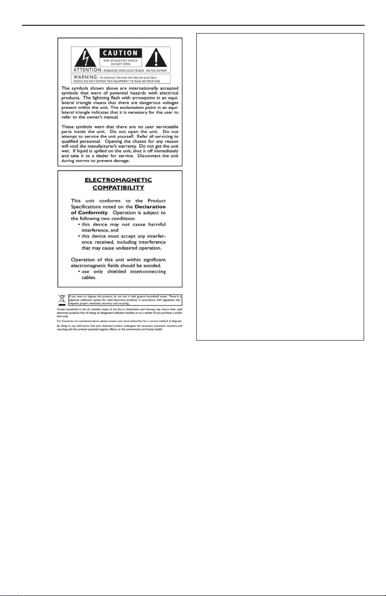
Front Panel
12 20
14
6 7 9108 2426 2527
11
15 16 17 18
1
2
3
4
5
19 22
21
23
13
Warmth 1.
This controls the warmth of the vocal by emulating a tube preamp.
Compressor2.
Adjusts the amount of compression or dynamic range on the lead voice.
De Esser 3.
Adjusts the aggressiveness of the sibilance suppression.
Noise Gate 4.
Controls the noise gate threshold for the microphone input.
Pre Effects 5.
When lit, all Pre Effects are active at their respective dialed in levels. When
the button is not lit, all Pre-Effects are turned off.
Pitch Correct Amount 6.
Adjusts the amount of the chromatic pitch correction on the lead voice.
Pitch Correct 7.
When lit, Pitch Correct is enabled. When the button is not lit, Pitch Correct is disabled.
3
Page 8

Reverb Types 8.
Studio
With Studio Reverb lit, a standard studio plate reverb is applied to the
vocals.
Room
With Room Reverb lit, the modeled natural reverb of a medium sized
room is applied to the vocals.
Hall
With Hall Reverb lit, the simulated acoustic reverb of a large concert hall is
applied to the vocals.
Reverb Level9.
This adjusts the amount of the selected reverb that is applied to the vocals
when Reverb is enabled.
Reverb10.
When lit, the selected reverb is enabled. When the button is not lit, Reverb
is disabled.
Signal LED Indicators 11.
Vocal Signal Strength
This light represents the signal strength of both the Mic In and Line In.
When lit green, the vocal input signal is at a sufficient level. When lit amber,
the signal strength is nearing the VL3D limiting point. When lit red, the limiter is active and the Mic/Line Input Level adjustment should be reduced.
Guitar Signal Strength
This light indicates the signal strength at the Guitar In. When lit green, a
sufficient guitar input signal is present. When lit amber, the signal strength
is approaching the limit. When lit red, the guitar signal is clipping and the
VL3D Guitar Sensitivity setting should be changed to Lo.
Note: If the Guitar Signal Strength LED is not lit when playing your guitar,
change the VL3D Guitar Sensitivity setting to Hi.
MIDI
This light flashes green when MIDI activity is detected on either the MIDI
In or USB MIDI ports.
USB
This is lit blue when the USB port is connected to a computer.
Tuner Bars12.
These are used by the Guitar Tuner to signify the flat or sharp deviation of
the note played from the target note.
4
Page 9

Display13.
This display shows the Guitar Sensitivity, Guitar Tuner target note, selected
Key in Acappella mode and is used for the MIDI Configuration Menu.
Musical Indicators 14.
#
In Acappella and Tuner modes, this indicates the selected Key/Note shown
on the Display as being Sharp or Flat.
Maj Min
In Acappella mode, this defines the selected Scale as Major or Minor.
Tuner15.
Pressing this button will both enter and exit the Guitar Tuner.
Key –16.
In Acappella mode, this button is used to cycle through the available Key
selections. In the MIDI Configuration Menu, this button is used to cycle
back through the parameter options.
Scale +17.
In Acappella mode, this button is used to toggle the Scale between Major
and Minor. In the MIDI Configuration Menu, this button is used to increment through the parameter options.
MIDI18.
Pressing this button enters the MIDI Configuration Menu and cycles
through the five configurable options. The button lights to indicate the
MIDI Configuration Menu is in use. This menu is automatically exited after
cycling past the last item. To exit the menu earlier, hold the MIDI button
until the LED turns off.
Harmony Patch19.
This button cycles through the five Harmony Patches on the currently
selected bank defined by the A/B button color. To save altered harmony
settings to the current Harmony Patch and the current A/B part, hold the
Harmony Patch button until the selected Patch Number flashes.
Note: You must save each A/B part individually.
Harmony Patch Number20.
This indicates which of the five Harmony Patches is presently selected.
Note that each Harmony Patch has two harmony settings defined by the
A/B button and color.
5
Page 10

Mode21.
Pressing the Mode button cycles through the four Harmony Modes; mu-
®
MIDI, musIQ Guitar, Acappella and Notes.
sIQ
Gender22.
There are individual Gender controls for each of the two Harmony Voices.
By pressing the Gender button of the corresponding Harmony Voice, you
can cycle through the Gender shifts from Male (M) to Female (F) as indicated on the Gender Display above. Note that when there are no bars lit
on the Gender Display, the Gender setting is disabled for the corresponding Harmony Voice.
Voicing23.
There are individual Voicing controls for each of the two Harmony Voices.
By pressing the Voicing button of the corresponding Harmony Voice, you
can cycle through the Voicing options as indicated on the Voicing Display
above. Note that when there are no bars lit on the Voicing Display, the
Voicing shift is disabled for the corresponding Harmony Voice.
Note: The exact note choice of the various Voicing shift settings depends
on the Harmony Mode selected and related variables such as current note
or chord, chord history and lead voice note.
Harmony Mix24.
This adjusts the mix of Lead Voice with the Harmony Voices at the outputs.
With the knob fully counter-clockwise, only the Lead Voice is present at
the outputs with no Harmony Voices. With the knob fully clockwise, only
the Harmony Voices will be heard at the outputs with no Lead Voice.
Humanize25.
This adjusts the amount of naturalness of the Harmony Voices. The intent
is to make the harmonies sound more like real backup singers by introducing variations in the timing and pitch. Fully counterclockwise makes the
harmonies follow the lead very tightly. Fully clockwise and the harmonies
are quite loose.
Harmony On / Off26.
This button turns the Harmony Voices on and off. When the button is lit,
the Harmony Voices are enabled. When the light is off, the Harmony Voices
are disabled.
Part A / B27.
This button toggles between the A and B Parts of the selected Harmony
Preset. Green indicates Part A, red indicates Part B.
6
Page 11

Rear Panel
162 3 4 5 9 11 12 14 13
7 8 10
Power Input1.
Connect only the supplied PS-0913AC adapter here to power the VL3D.
USB MIDI2.
This USB MIDI computer interface accepts MIDI Notes, Continuous Control, and Program Change messages for harmony generation and control. It
is also used for firmware updates.
MIDI In 3.
The MIDI In accepts MIDI Notes, Continuous Control, and Program
Change messages for harmony generation and control. When the VL3D's
USB port is connected to a computer, any data received at the MIDI In jack
is passed up via USB to your computer recording/sequencer application.
MIDI Thru4.
The MIDI Thru jack works in two different ways:
a. When the USB port is not connected to a computer, this jack passes
on all MIDI data received at MIDI In jack.
b. When the USB port is connected to a computer, all MIDI data
received via USB from the computer is passed through this jack.
Note: When USB is connected, the VL3D's MIDI In does not pass data
to the MIDI Thru jack
Headphone Output5.
The stereo main mix is supplied to this 1/8” TRS Headphone Output.
Guitar Thru6.
The guitar signal received on the Guitar In is passed through the ¼” unbalanced Guitar Thru to connect to the guitar effects or amplifier.
7
Page 12

Guitar In7.
This ¼” unbalanced Guitar In connects directly to the guitar for use by
®
musIQ
Guitar Mode harmony generation.
Note: It is important for the VL3D to be the first device in the guitar signal
chain to ensure proper analysis of the guitar signal for harmony generation.
Ground Lift Switch8.
This switch lifts the Guitar In and Guitar Thru ground references to eliminate any noise hum issues that may arise from system ground loops.
Line Out (L & R)9.
These ¼” balanced TRS / unbalanced TS Line outputs provide a stereo mix
of Lead Vocal and Harmony Voices. Use only the Left Line output when a
mono mix is needed.
Footswitch10.
This ¼” TRS input is for an optional three-button footswitch such as the
DigiTech FS3X or FS300.
Line In11.
This ¼” balanced TRS / unbalanced TS input accepts a line level signal supplying the Lead Vocal. Note: When the Line In input is connected, do not
connect anything to the Mic In input.
Mic In12.
This balanced XLR input accepts microphone level signals. Note: When
the Mic In input is connected, do not connect anything to the Line In input.
Mic / Line Input Level 13.
This adjusts the input level of the Lead Vocal signal from both the Mic In
and Line In. The relative signal strength can be determined at the Vocal
signal strength indicator on the front panel.
48V14.
Pressing this switch to the inward position turns on the 48V phantom
power to the Mic In. With the switch in the outward position, the 48V
phantom power is turned off.
Note: Phantom power is normally only needed with condenser microphones and should never be used with ribbon microphones. To avoid
damaging the microphone, please consult your microphone documentation
to ensure phantom power is applied only when appropriate.
8
Page 13

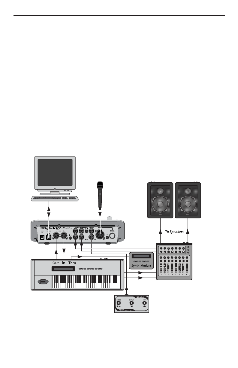
Using the VL3D with a Keyboard
1 2 3 4 5 6 L R
To Speakers
The VL3D can provide fully automatic harmony if you are using a keyboard.
Simply connect the MIDI output of your keyboard to the MIDI In of the VL3D.
The VL3D monitors what you are playing on the keyboard and adjusts the
harmonies to fit over the accompaniment. For best results, make sure your
keyboard is tuned to concert pitch (A=440).
You will need to select the musIQ® MIDI mode using the Mode
button. By default, the VL3D listens to all MIDI channels. If
desired you can set the VL3D to listen to a particular MIDI
channel. To do that, first enter the MIDI Configuration Menu by
pressing the MIDI button.
The MIDI button will light and the letters CH will appear on the display momentarily. This indicates that the
MIDI channel is set to be adjusted. The CH will soon be
replaced by the currently selected MIDI channel.
Use the Key + and Scale – buttons to select the desired
MIDI channel. The choices are AL (all) and 1 to 16.
Press and hold the MIDI button exit MIDI setup mode.
9
Page 14
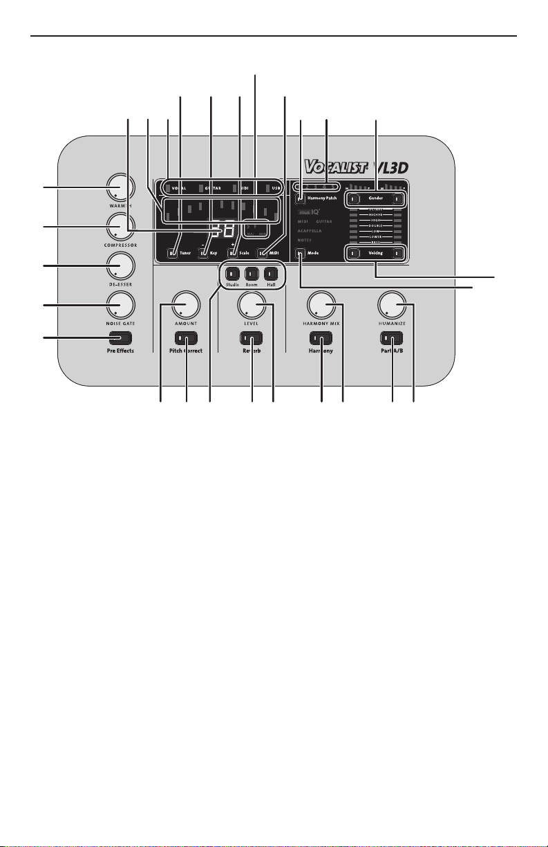
Using the VL3D with a Guitar
To Speakers
1 2 3 4 5 6 L R
The VL3D can provide fully automatic harmony for a guitar player. Simply
route your guitar signal through the VL3D using the Guitar In and Guitar Thru
jacks. The VL3D monitors what you are playing on the guitar and adjusts the
harmonies to fit over the accompaniment.
You will need to select the musIQ® Guitar mode using the
Mode button.
The VL3D must be first in the guitar signal chain to ensure proper musIQ
analysis and harmony generation. Connect the guitar directly to the Guitar In.
The Guitar Thru output can then be connected to any effects pedals before the
amp.
10
Page 15

Guitar Sensitivity
While playing the guitar, the Guitar Signal Strength indicator should be green
or amber. If the Guitar Signal Strength indicator does not light when you play,
the guitar signal level may be too low and the Guitar Sensitivity should be
changed to Hi. If the Guitar Signal Strength indicator lights red, then the Guitar
Sensitivity should be changed to Lo.
To set the Guitar Sensitivity hold the Tuner button
until the new Guitar Sensitivity setting of Hi or Lo
is displayed. The most common setting is Lo Guitar
Sensitivity.
Tuner
It is important for your guitar to be properly tuned in order for the musIQ®
technology to generate the best sounding harmonies. Alternate tunings (for example, DADGAD or tuning down) are fine, as long as the built-in tuner shows
each string as in tune. If you are using an external tuner, make sure that the
reference is set to 440 Hz.
To use the built-in tuner, press the Tuner button to
start the Guitar Tuner. The Tuner button will flash
while the Tuner mode is active. Note that for the
Tuner to work properly it needs to receive adequate
guitar signal strength, which is indicated by the Guitar
Signal Strength indicator.
As each string is individually played, the closest note to that played will appear
on the Display and the Tuner Bars will show the deviation in pitch from the
target note. If the string is in tune with the target note, the green center Tuner
Bar will be lit. Bars to the left will light if the string is flat and bars to the right
if the string is sharp.
When all strings are in tune, press the Tuner button to exit the Guitar Tuner.
11
Page 16
Using the VL3D with a Computer
There are two options when using the VL3D with a computer:
The VL3D can be connected directly to a computer via its USB port and 1.
used as a MIDI interface.
The VL3D can be connected to a a separate MIDI interface already con-2.
nected to a computer.
VL3D used as a MIDI Interface
When the VL3D is connected directly to the computer via USB, it acts as a
MIDI interface. Data sent into the MIDI In of the VL3D is passed on to the
computer through the USB port. Similarly, all data sent from the computer to
the VL3D is passed through the VL3D and appears at the MIDI Thru jack.
Note: When USB is connected, the VL3D's MIDI In does not pass data to the
MIDI Thru Jack
12
Page 17

VL3D connected to a MIDI Interface
When the VL3D is not connected to a computer using the USB port, all MIDI
data sent to the MIDI In of the VL3D is passed on to the MIDI Thru jack. This
allows you to chain other MIDI devices, such as sound modules, to the VL3D.
13
Page 18

Pre-Effects
The VL3D contains a variety of Pre-Effects to enhance your vocal sound.
Warmth
This controls the amount of warm subtle distortion from the
tube preamp amp model, adding a degree of vintage tone.
Compressor
The Compressor gives the ability to tighten up the dynamic
range of the Lead Voice. The Compressor threshold, ratio, attack and release are all adjusted automatically to provide the
right amount of overall compression.
De Esser
This adjusts the aggressiveness of the De Esser suppression
of sibilant sounds that may be over-emphasized by the microphone.
Noise Gate
This control defines the Noise Gate threshold for the microphone input. Below the defined threshold, low level unwanted
background noise is muted and will not pass through to the
main outputs.
14
To collectively enable and disable all Pre Effects, press the Pre
Effects button. When lit, all Pre Effects are enabled.
Page 19

Pitch Correct
This corrects the Lead Voice to a 12-note chromatic scale.
Use the Amount knob to set the aggressiveness of the pitch correction.
When the Pitch Correct button is lit red, Pitch Correct is enabled.
When the button is not lit, Pitch Correct is disabled.
Reverb
There are three selectable room sizes for the Reverb effect. The active reverb
type is indicated by the lit button.
Studio Reverb simulates a studio plate reverb. Room Reverb
simulates the natural reverb of a medium sized room. Hall
Reverb simulates the reverb of a large concert hall.
The Reverb Level knob adjusts the amount of overall reverb
applied to the mix.
When the Reverb button is lit, the Reverb is enabled. When
the button is not lit, Reverb is disabled.
15
Page 20

Harmony Patches and Parts
Singers need a way to configure different Harmony
Voicings for use in different songs. To accommodate this, the VL3D provides Harmony Patches. This
allows the singer to specify the Harmony Mode,
Voicing, and Gender Settings in advance and recall
them when needed during a performance. There are five harmony patches.
Each harmony patch also has an A Part and a B Part. Typically this will be used
to specify one harmony setting for, say, the verse and a separate setting for the
chorus. During the song it is easy to toggle back and forth between the A Part
and the B Part with the simple press of a button either on the front panel or
on the optional footswitch.
Each Harmony Patch stores the Harmony Mode, Harmony Voicing and Harmony Gender settings. Harmony Patches do not store the Pre Effects, Pitch
Correct, Reverb, Harmony Mix, Humanize or Harmony On/Off parameters.
Store and Recall a Patch
To recall a patch, simply select it using the Harmony Patch button to cycle
through the saved Patches of stored Harmony settings.
Once you have made changes to a harmony patch, you can store the changes
to the selected Patch by pressing and holding the Harmony Patch button until
the lit Harmony Patch Number flashes twice.
Note: You must make changes to the Patch location you wish to save them to
as there is no way to save changes made in Patch 1 to Patch 5.
Harmony A/B Parts
Each patch contains two independent harmony settings: Part A and
Part B. You can select between these two Parts using the A/B button on the face of the VL3D or with an optional 3-button Footswitch. The active Part is indicated by the bi-color LED on the Part
button. Green indicates Part A. Red indicates Part B.
Note: You must store each part individually. For example, if you store Part A to
a harmony patch, Part B will not be saved unless you select it and store it also.
16
Page 21

Harmony Modes
The Harmony Mode determines how the Harmonies will be controlled for
the current Harmony Patch. Pressing the Mode button cycles through the four
Harmony Modes.
musIQ® Harmony Mode
This mode uses musIQ® technology to automatically generate the harmonies
based on the music being played on either a MIDI keyboard or a guitar. Just
play naturally and musIQ technology will analyze the music and make sure that
the harmonies are musically correct in the context of the accompaniment. The
harmony is chosen based on the Voicing selected.
musIQ MIDI
This mode uses musIQ technology to automatically generate
the harmonies based on the MIDI input.
musIQ Guitar
This mode uses musIQ technology to automatically generate
the harmonies based on the guitar input.
Acappella Harmony Mode
Acappella mode is intended for vocalists not using a guitar or
MIDI keyboard as a guide instrument. In Acappella mode, you
must use the Key and Scale buttons to set the desired Key and
Scale for the Harmony Voices. Use the Key button to cycle
through the available key or root note selections. Use the Scale
button to toggle the selections and define the scale as Major or
Minor.
17
Page 22

Notes Harmony Mode
In MIDI Notes mode the VL3D will “sing” up to four notes
being played on the MIDI keyboard. For example if you play an
E, G, C, and E notes, then four harmonies will be generated at
those notes.
In MIDI Notes mode, Harmony Gender controls apply to the first two of four
Harmony Voices. Gender control of the remaining Harmony Voices three and
four can be achieved by using MIDI CC messages for these Harmony Voices.
Since in MIDI Notes mode the Harmonies are controlled directly by the keyboard or sequencer, there is no need to specify a harmony voicing.
Normally, all four harmony voices are controlled using a single MIDI channel.
There is another more powerful mode which is most often used when sequencing the harmony parts. This is 4-channel MIDI mode. In this mode each
harmony voice is controlled from a separate MIDI channel. This allows one to
specify a separate Gender setting for each harmony voice (see MIDI CC Messages section later in this document). This mode provides complete control of
the harmonies.
Harmony Voicing
These set the Voicing for the two Harmony Voices in
®
musIQ
ing button sets the Voicing for one of the Harmony
Voices by cycling through the Voicing options.
and Acappella harmony modes. Each Voic-
The Double option sets the Harmony Voice to “sing”
the same note as the lead voice. This provides a rich
doubling sound. By cycling through the options until
none of the options are lit, the corresponding Har-
mony Voice is turned off completely.
Because musIQ technology adjusts the harmony voices depending on the
singers note and the music being played on the guitar or keyboard, it is not
possible to exactly specify the exact musical interval using the harmony voicing
controls. However, it may be convenient to think of the High and Higher settings to be roughly a third and a fifth above the sung note. Similarly, the Low
and Lower settings can be thought of as being roughly a third and a fifth below
the sung note. The Bass setting is a full octave below.
18
Page 23

Harmony Gender
The VL3D has the option of gender shifting the Harmony Voices to change the character of the virtual
harmonizing backup singers.
There are individual Gender controls for each of the two Harmony Voices.
By pressing the Gender button of the corresponding Harmony Voice, you can
cycle through the Gender shifts from Male (M) to Female (F) as indicated on
the Gender Display above.
The five Gender options for each Harmony Voice are Heavy Male Gender, Light
Male Gender, Light Female Gender, Heavy Female Gender and None. When
none of the Gender options are lit, this represents no Gender shift is applied,
leaving the corresponding Harmony Voice with the same Gender as the Lead
Voice.
Harmony Mix
This adjusts the mix of Lead Voice with the Harmony Voices at
the outputs. With the knob fully counter clockwise, only the Lead
Voice is present at the outputs with no Harmony Voices. With the
knob fully clockwise, only the Harmony Voices will be heard at the
outputs with no Lead Voice.
Humanize
Humanize controls a handful of parameters that affect the perceived naturalness of the Harmony Voices. The parameters affect
Harmony Voice aspects such as the time delay between onsets of
the Harmony Voices, steadiness of the pitch and the pitch scoop of
the voices as they shift from one note to the next.
Harmony On/Off
This button turns the collective Harmony Voices on and off. When
the button is lit, the Harmony Voices are enabled. When the light is
off, the Harmony Voices are disabled.
19
Page 24

MIDI Configuration
The parameters in the MIDI Configuration Menu are globally shared across all
Harmony Patches.
Enter the MIDI Configuration Menu by pressing the MIDI button. The MIDI
button will light, signifying the menu is active. The menu options will appear on
the Display. Press MIDI again to cycle to the next of five MIDI Menu parameters. Use the Key and Scale buttons to cycle through the available options for
each of the MIDI Menu parameters.
Exiting the MIDI Configuration Menu can be achieved in two ways. Press and
hold the MIDI button until the LED turns off or simply cycle past the last of
the five menu parameters.
MIDI Channel
The first parameter in the MIDI Configuration menu is
MIDI Channel, denoted on the Display by CH.
After a second the Display will show the currently
selected MIDI channel number. The MIDI channel can be
changed to 1 through 16 or set to AL.
If AL is selected, the VL3D will respond to MIDI input
from all 16 MIDI channels.
Split Point
The VL3D can be configured to respond to MIDI notes in a particular active
zone of the keyboard, while ignoring received MIDI notes from the inactive
zone. After a second the SP on the display will be replaced with the currently
selected Split Point.
To define a new Split Point, you must play two notes on
your keyboard. The first note played defines the Split
Point note that separates the active zone from the inactive zone. The second note played defines the inactive
region as above or below the specified Split Point.
The display shows the Split Point note and octave. The
Tuner Bars provide a visual indication of the Split Point
and zones. Each of the Tuner Bars represents an octave
with the green center being middle C.
In the figure above, the Split Point is E in the octave starting at Middle C and
the VL3D is processing all MIDI notes in the active zone below the Split Point.
To clear the current split point simply press the + or – key.
20
Page 25

1-Channel and 4-Channel MIDI Mode
This parameter provides two options for controlling the harmony voices
in MIDI Notes Harmony Mode. All four Harmony Voices can be controlled
from the same MIDI channel (1-Channel MIDI Mode) or from four separate
(4-Channel MIDI Mode). By using a separate MIDI channel for each voice it is
possible to specify a different gender for each voice and precisely control the
notes that voice “sings”.
On the Display, 1C signifies 1-Channel MIDI Mode,
while 4C represents 4-Channel MIDI Mode.
In 4-Channel MIDI Mode, the four sequential MIDI
channels are used starting with the MIDI Configura-
tion Menu MIDI Channel as the starting point. For
example, if the MIDI Channel is defined as 12, then
the 4 Harmony Voices are individually controlled by
MIDI channels 12, 13, 14, and 15. If the MIDI Channel
is defined as AL, then channels 1, 2, 3, 4 will be used.
CC MIDI Channel
The VL3D can be configured to look for MIDI Control Change messages on
a different MIDI channel than is used for MIDI notes. These Control Change
message include program change messages and continuous control messages
as detailed in the MIDI Messages section on page 23.
After one second, CC on the Display will be replaced
by the current selected CC MIDI Channel.
The Control Change MIDI Channel can be changed to
1 through 16 or AL.
If AL is selected, the VL3D will respond to Control
Change messages from all 16 MIDI channels.
If no MIDI Control Change is desired, select the
Channel to Off (OF).
21
Page 26

Program Change
The VL3D can be configured to accept received Program Change messages, or
this capability can be turned off. The VL3D looks for Program Change messages on the Control Change MIDI channel as specified in the previous section.
After one second, PC on the Display will be replaced
by the current status of Program Change.
on indicates the VL3D will accept PC messages, pro-
vided the MIDI CC MIDI channel is not set to OF.
OF indicates that no received PC messages will be
processed.
Saving Global Parameters
The following Global Parameters are automatically saved when changed:
Guitar Sensitivity•
MIDI Channel•
MIDI Split Point•
MIDI Notes Mode Configuration (1-Channel or 4-Channel)•
MIDI CC Channel •
MIDI Program Change Enable•
External Footswitch
The VL3D supports the use of an optional external ¼” TRS three-button footswitch such as the DigiTech FS3X or FS300.
The buttons of the External Footswitch perform the following fixed functions:
Left footswitch: Toggle Harmony Bank A/B
Middle footswitch: Advance Harmony Patch
Right footswitch: Harmony On/Off
The VL3D also will support a single button footswitch provided it is a normally
open switch. In this case the switch will control Harmony On/Off.
22
Page 27

MIDI Messages
Notes
Standard note on and note off MIDI messages are supported for use with the
®
musIQ
Program Change
The VL3D supports 10 PC messages to provide access to all 10 Harmony
Patch and A/B Part locations. These messages are received on the MIDI Channel specified by CC MIDI channel.
MIDI and MIDI Notes Harmony Modes.
PC Number Patch Part
1 1 A
2 1 B
3 2 A
4 2 B
5 3 A
6 3 B
7 4 A
8 4 B
9 5 A
10 5 B
System Exclusive
Since all parameters are controllable by MIDI CC the VL3D does not support
parameter edits via SysEx.
Factory Reset
In order to restore the presets and settings to their factory defaults follow
these steps.
Make sure the VL3D is powered off.1.
Press and hold the Key (-) and Scale (+) buttons.2.
While continuing to hold the Key (-) and Scale (+) buttons, power up the 3.
VL3D.
The VL3D will go through the factory initialization process. During this 4.
process it will turn on successively more LEDs. When complete, all the
green, yellow and red LEDs in the tuning display will be lit.
When all the tuning display LEDs are lit, release the Key (-) and Scale (+) 5.
buttons and power down the unit. The Factory Reset procedure is complete.
23
Page 28
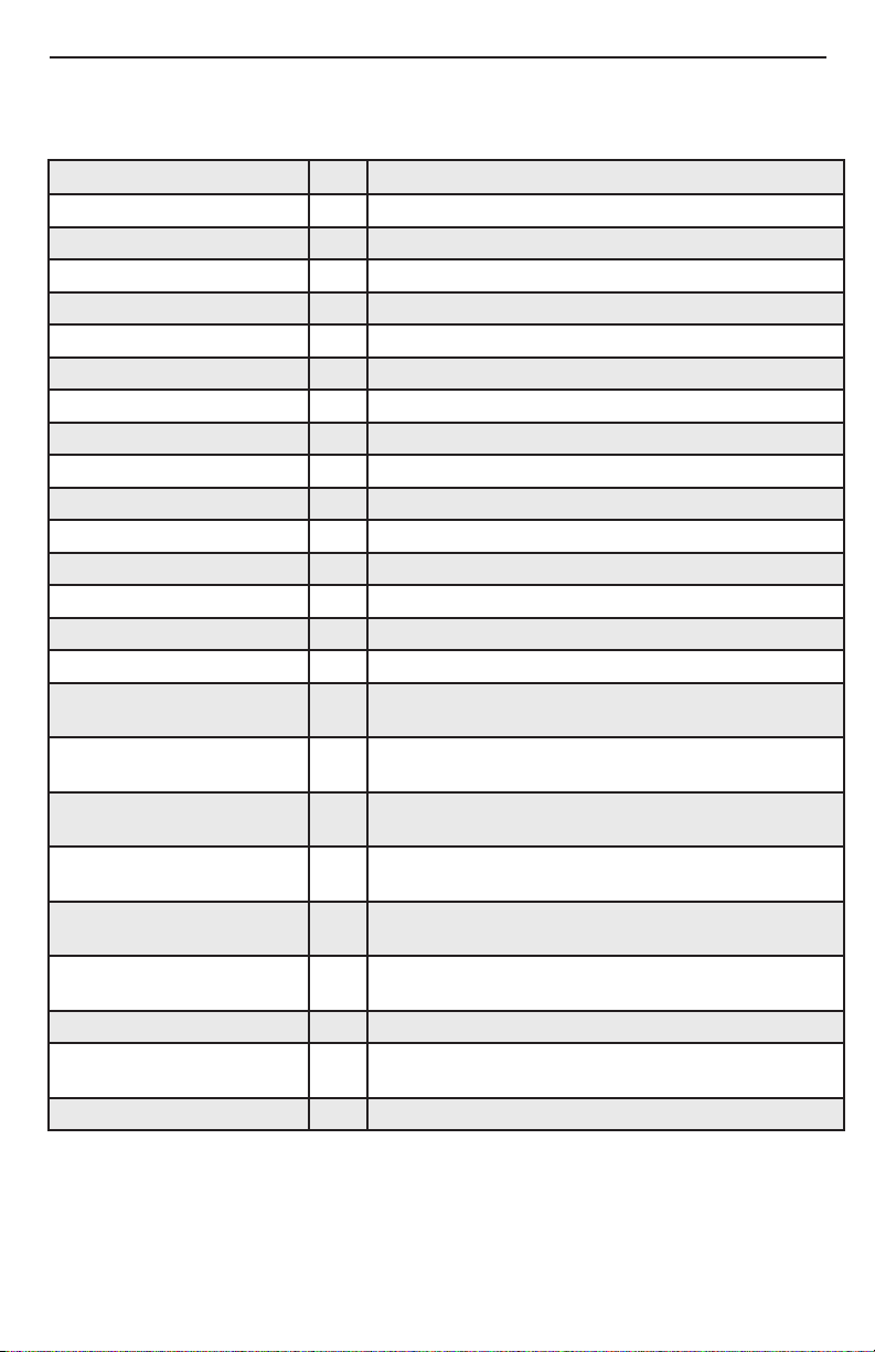
Continuous Controller
Below is a listing of the CC messages supported by the VL3D. These messages
are received on the MIDI channel specified by CC MIDI Channel.
Parameter CC Range, Comments
Modulation 1 0 – 127, Controls Vibrato Intensity
Sustain Pedal 64 0 - 63 = Off, 64 - 127 = On
Pre-Effects On/Off 85 0 - 63 = Off, 64 - 127 = On
Pitch Correct On/Off 86 0 - 63 = Off, 64 - 127 = On
Reverb On/Off 87 0 - 63 = Off, 64 - 127 = On
Harmony On/Off 88 0 - 63 = Off, 64 - 127 = On
Warmth 102 0-127
Compressor 103 0-127
De Esser 104 0-127
Noise Gate 105 0-127
Pitch Correct Amount 106 0-127
Reverb Type 107 0-Studio, 1-Room, 2-Hall
Reverb Level 108 0-127
Harmony Mix 109 0-127
Humanize 110 0-127
Voice 1 Voicing 111 0=Off, 1=Bass, 2=Lower, 3=Low, 4=Double, 5=High,
Voice 2 Voicing 112 0=Off, 1=Bass, 2=Lower, 3=Low, 4=Double, 5=High,
Voice 1 Gender 113 0 = None, 1=Strong Male Gender, 2=Light Male Gender,
Voice 2 Gender 114 0 = None, 1=Strong Male Gender, 2=Light Male Gender,
Voice 3 Gender
MIDI Notes Mode Only
Voice 4 Gender
MIDI Notes Mode Only
Harmony Mode 117 0=musIQ
Acappella Key (Tonic) 118 0=C, 1=C#, 2=D, 3=D#, 4=E, 5=F, 6=F#, 7=G, 8=G#,
Acappella Scale 119 0=Major, 1=Minor
6=Higher, 7=Octave
6=Higher, 7=Octave
3=Light Female Gender, 4=Strong Female Gender
3=Light Female Gender, 4=Strong Female Gender
115 0 = None,1=Strong Male Gender, 2=Light Male Gender,
3=Light Female Gender, 4=Strong Female Gender
116 0 = None1=Strong Male Gender, 2=Light Male Gender,
3=Light Female Gender, 4=Strong Female Gender
®
Midi, 1=musIQ Guitar, 2=Acappella, 3=Notes
9=A, 10=A#, 11=B
24
Page 29

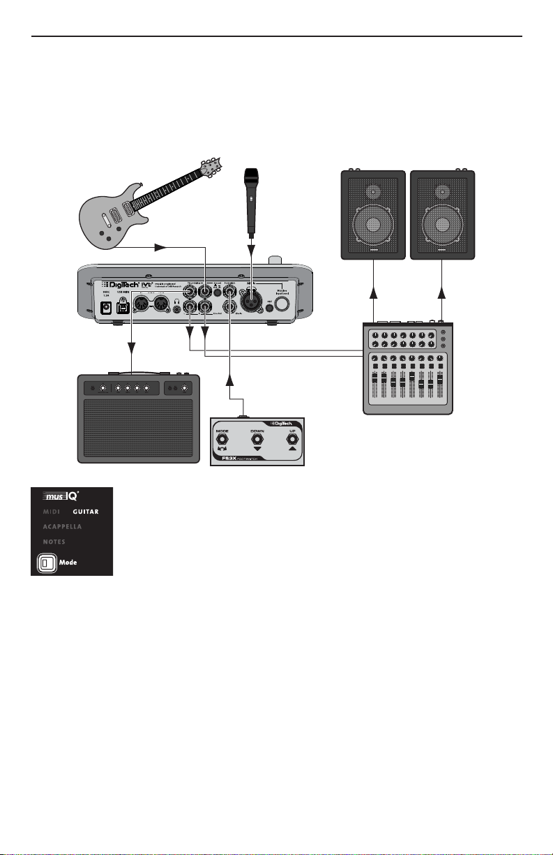
Reverb
Harmony
Pre-Effects
Reverb
Effects
De-Esser
Compressor
Limiter
Noise Gate
Stereo Return
Stereo Send
Vocal
Input
Warmth
Stereo Mixer
with Pans and
Gains
Pitch Correct
Harmony
Voice 1
Harmony
Voice 2
Harmony
Voice 3
Harmony
Voice 4
Voices 3 & 4 only available
in MIDI Notes Mode
L
R
Effects Block Diagram
25
Page 30

Specifications
Mic Preamp:
Connector: XLR balanced
Phantom Power; +48 V
Input Sensitivity @ 0dBFS: -22 dBu to +18 dBu
Equivalent Input Noise (EIN): -127 dBu, 20 Hz - 20 kHz (A-Weighted)
Input Impedance: 6 kΩ Balanced
Line Inputs:
Connector: ¼” TRS balanced / unbalanced
Input Sensitivity @ 0dBFS: -10 dBu to +30 dBu
Input Impedance: 26 kΩ Balanced, 13 kΩ Unbalanced
Guitar Input / Guitar Thru:
Connectors: ¼” unbalanced
Impedance: >2.2 MΩ
Line Outputs:
Connectors: ¼” TRS impedance balanced / unbalanced
Output Level @ 0dBFS: +14.5 dBu
Output Impedance: 2.2 kΩ balanced / 1.1 kΩ unbalanced
Headphone Output:
Connector: 1/8” (tip = left, ring = right, sleeve = ground)
Impedance: 100 Ω per channel
Input (Line) to Output (Line) Performance:
Dynamic Range: >107 dB, 20 Hz - 20 kHz (A-Weighted)
THD + Noise @ Min Gain: 0.004% @ 1 kHz
Frequency Response @ Max Gain: -3 dB @ 30 Hz and 21 kHz
Analog to Digital / Digital to Analog Converters
Resolution: 24 bits
Sampling Rate: 44.1 kHz
Digital Connections:
MIDI In: 5-pin Din
MIDI Thru: 5-pin Din
USB: USB 1.1 (USB 2.0 compatible)
Power
US and Canada: 120 VAC, 60 Hz Adapter: PS0913B - 120
Japan: 100 VAC, 50/60 Hz Adapter: PS0913B - 100
Europe: 230 VAC, 50 Hz Adapter: PS0913B - 230
UK: 240 VAC, 50 Hz Adapter: PS0913B - 240
Australia: 240 VAC, 50 Hz Adapter: PS0913B - 240-AU
Power Input: 9 VAC 1.3 A
Power Consumption: 11 watts
Product Dimensions: 6.382”(L) x 10.138” (W) x 2.744” (H)
162.1mm(L) x 257.5mm(W) x 69.7mm(H)
Weight: 3.3 lbs., 1.5 kg
26
Page 31

27
Page 32

DigiTech
®
8760 South Sandy Parkway
Sandy, Utah 84070
PH (801) 566-8800
FAX (801) 566-7005
http://www.digitech.com
Printed in the USA
®
Vocalist
Live 3D Owner’s Manual 18-0588-A
©2009 Harman International Industries, Incorporated, all rights reserved.
DigiTech and Vocalist are trademarks of Harman International Industries, Inc.
®
musIQ
is a registered trademark of 3dB Research Ltd.
28
 Loading...